Journal of Catalysis 191, 282–293 (2000) doi:10.1006/jcat.2000.2819, available online at http://www.idealibrary.com on The Controlled Oxidation of Hydrogen from an Explosive Mixture of Gases Using a Microstructured Reactor/Heat Exchanger and Pt/Al 2 O 3 Catalyst Michael T. Janicke, * Harry Kestenbaum, * Ulrike Hagendorf, * Ferdi Sch ¨ uth, *,1 Maximilian Fichtner,† and Klaus Schubert† * Max Planck Institut f ¨ ur Kohlenforschung, Kaiser-Wilhelm-Platz 1, D-45470 M¨ ulheim an der Ruhr, Germany; and †Forschungszentrum Karlsruhe GmbH, Postfach 3640, D-76021 Karlsruhe, Germany Received June 7, 1999; revised December 13, 1999; accepted January 6, 2000 DEDICATED TO PROF. D. H ¨ ONICKE ON THE OCCASION OF HIS 60TH BIRTHDAY. With advances achieved in the area of microreactor technology, new possibilities for the use of microchannel reactors in the field of heterogeneous catalysis are now attainable. By exploiting these microstructured reactors for their relatively high surface-to-volume ratio and the inherent safety due to dimensions below the quench- ing distance at which explosions can propagate, hazardous reac- tion mixtures can be handled safely. The aim of this paper is to present the results on the catalytic H 2 /O 2 reaction obtained from an alumina-coated microstructured reactor/heat exchanger that has been impregnated with a platinum catalyst. With this reactor, ex- plosive mixtures of gaseous hydrogen and oxygen (up to 50% by volume of H 2 in O 2 ) were safely handled and the hydrogen was completely converted to water without explosions by maintaining a heterogeneously catalyzed reaction. The homogeneous reaction was prevented through efficient removal of the heat evolved from this highly exothermic reaction with cooling gas flowing in the heat exchanger channels of the reactor. It is anticipated that the use of microstructured reactors in catalysis research will add new levels of safety and control in studying chemical systems that necessarily involve explosive mixtures of gases. c 2000 Academic Press Key Words: microstructured reactor; H 2 /O 2 reaction; Pt catalyst; Al 2 O 2 support. INTRODUCTION In recent years, the field of microreaction technology has emerged as an area of interest for reaction engineering studies and chemical industries (1–3). Much consideration has been paid to microstructured reactors, also known as microchannel reactors, because of distinct advantages they provide over conventional reactor design. Microstructured reactors’ benefits include their inherent safety, improved process control, and rapid implementation. The small size of the microchannels translates to smaller concentrations 1 To whom correspondence should be addressed. E-mail: schueth@ mpi-muelheim.mpg.de. Fax: +49 (0) 208 306-2995. of dangerous chemicals and the microstructured features result in reactor dimensions that are less than the quench distances for explosions, ultimately providing an opportu- nity to produce hazardous chemicals on-site safely and in a cost-effective manner that eliminates the need to transport these species (4–7). Improved process control can be real- ized because of fast response times in the microstructured reactors (4). These improved response times arise from high surface-to-volume ratios that lead to efficient heat and mass transfer, for example. Additionally, microreactors can be designed to provide rapid mixing in the micron-sized chan- nels, a further advantage when enhanced process control and response times are required. Lastly, microreactor tech- nology is supposed to be quickly transferred from labora- tory or pilot plant stages to production facilities because the microstructures with quasi-identical reaction channels can be scaled up to achieve throughputs in the range of 100,000 t/year of liquids with one or a few devices (8). There are many examples of chemical reactions that are well suited for microreactors. A brief list of possibilities includes partial oxidation reactions in which kinetically fast reactions must be quenched to prevent full oxidation (8–11), multiphase reactions that are mass transfer limited but require effective mixing (5), reactions that are highly exothermic or involve explosive mixtures such as the H 2 /O 2 reaction (5, 12, 13), and finally reactions that involve toxic precursors or products (hydrogen cyanide or phosgene are two plausible candidates) (6, 7). Of these, the H 2 /O 2 reac- tion is a particularly demanding test case in that the reac- tion is extremely exothermic and nearly all mixtures of H 2 in O 2 gases are explosive. For these reasons, the H 2 /O 2 reac- tion over a Pt/Al 2 O 3 catalyst was selected for this research in an effort to demonstrate the strength of microreactors in safely handling hazardous chemical reactions. Whereas this work focuses on the reaction of hydrogen and oxy- gen on a platinum catalyst, much broader opportunities have been realized in other areas of oxidation chemistry 0021-9517/00 $35.00 Copyright c 2000 by Academic Press All rights of reproduction in any form reserved. 282

Welcome message from author
This document is posted to help you gain knowledge. Please leave a comment to let me know what you think about it! Share it to your friends and learn new things together.
Transcript
Journal of Catalysis 191, 282–293 (2000)
doi:10.1006/jcat.2000.2819, available online at http://www.idealibrary.com on
The Controlled Oxidation of Hydrogen from an Explosive Mixture of GasesUsing a Microstructured Reactor/Heat Exchanger and Pt/Al2O3 Catalyst
Michael T. Janicke,∗ Harry Kestenbaum,∗ Ulrike Hagendorf,∗ Ferdi Schuth,∗,1
Maximilian Fichtner,† and Klaus Schubert†∗Max Planck Institut fur Kohlenforschung, Kaiser-Wilhelm-Platz 1, D-45470 Mulheim an der Ruhr, Germany; and †Forschungszentrum
Karlsruhe GmbH, Postfach 3640, D-76021 Karlsruhe, Germany
Received June 7, 1999; revised December 13, 1999; accepted January 6, 2000
DEDICATED TO PROF. D. HONICKE ON THE OCCASION OF HIS 60TH BIRTHDAY.
With advances achieved in the area of microreactor technology,new possibilities for the use of microchannel reactors in the fieldof heterogeneous catalysis are now attainable. By exploiting thesemicrostructured reactors for their relatively high surface-to-volumeratio and the inherent safety due to dimensions below the quench-ing distance at which explosions can propagate, hazardous reac-tion mixtures can be handled safely. The aim of this paper is topresent the results on the catalytic H2/O2 reaction obtained from analumina-coated microstructured reactor/heat exchanger that hasbeen impregnated with a platinum catalyst. With this reactor, ex-plosive mixtures of gaseous hydrogen and oxygen (up to 50% byvolume of H2 in O2) were safely handled and the hydrogen wascompletely converted to water without explosions by maintaininga heterogeneously catalyzed reaction. The homogeneous reactionwas prevented through efficient removal of the heat evolved fromthis highly exothermic reaction with cooling gas flowing in the heatexchanger channels of the reactor. It is anticipated that the use ofmicrostructured reactors in catalysis research will add new levelsof safety and control in studying chemical systems that necessarilyinvolve explosive mixtures of gases. c© 2000 Academic Press
Key Words: microstructured reactor; H2/O2 reaction; Pt catalyst;Al2O2 support.
INTRODUCTION
In recent years, the field of microreaction technology hasemerged as an area of interest for reaction engineeringstudies and chemical industries (1–3). Much considerationhas been paid to microstructured reactors, also known asmicrochannel reactors, because of distinct advantages theyprovide over conventional reactor design. Microstructuredreactors’ benefits include their inherent safety, improvedprocess control, and rapid implementation. The small sizeof the microchannels translates to smaller concentrations
1 To whom correspondence should be addressed. E-mail: [email protected]. Fax: +49 (0) 208 306-2995.
0021-9517/00 $35.00Copyright c© 2000 by Academic PressAll rights of reproduction in any form reserved.
28
of dangerous chemicals and the microstructured featuresresult in reactor dimensions that are less than the quenchdistances for explosions, ultimately providing an opportu-nity to produce hazardous chemicals on-site safely and in acost-effective manner that eliminates the need to transportthese species (4–7). Improved process control can be real-ized because of fast response times in the microstructuredreactors (4). These improved response times arise from highsurface-to-volume ratios that lead to efficient heat and masstransfer, for example. Additionally, microreactors can bedesigned to provide rapid mixing in the micron-sized chan-nels, a further advantage when enhanced process controland response times are required. Lastly, microreactor tech-nology is supposed to be quickly transferred from labora-tory or pilot plant stages to production facilities becausethe microstructures with quasi-identical reaction channelscan be scaled up to achieve throughputs in the range of100,000 t/year of liquids with one or a few devices (8).
There are many examples of chemical reactions that arewell suited for microreactors. A brief list of possibilitiesincludes partial oxidation reactions in which kineticallyfast reactions must be quenched to prevent full oxidation(8–11), multiphase reactions that are mass transfer limitedbut require effective mixing (5), reactions that are highlyexothermic or involve explosive mixtures such as the H2/O2
reaction (5, 12, 13), and finally reactions that involve toxicprecursors or products (hydrogen cyanide or phosgene aretwo plausible candidates) (6, 7). Of these, the H2/O2 reac-tion is a particularly demanding test case in that the reac-tion is extremely exothermic and nearly all mixtures of H2
in O2 gases are explosive. For these reasons, the H2/O2 reac-tion over a Pt/Al2O3 catalyst was selected for this researchin an effort to demonstrate the strength of microreactorsin safely handling hazardous chemical reactions. Whereasthis work focuses on the reaction of hydrogen and oxy-gen on a platinum catalyst, much broader opportunitieshave been realized in other areas of oxidation chemistry
2
CONTROLLED OXIDATION O
which also rely on explosive mixtures of hydrogen andoxygen (5).
The precarious nature of the hydrogen/oxygen reactionis a consequence of the exothermicity and the broad ex-plosion limits for H2; however, the challenges this systempresents are solved by using a microstructured reactor/heatexchanger. For the H2/O2 reaction,
H2(g)+ 12 O2(g)→ H2O(g) 1H =−57.9 kcal/mol
with the explosion limits for H2 in O2 ranging from 4% to94%, on a volume percent basis, and from 4% to 75% forH2 in air (14), the safety issues cannot be overstressed andexpensive equipment and reactors are normally requiredto handle the reaction. Microstructured reactors providemany advantages over conventional reactor designs, as isshown in this work with a stainless steel microstructuredreactor/heat exchanger. The small reactor minimizes theexplosion danger by possessing a small reactor volume,ca. 1 cm3, and the dimensions of the microchannels (140×200µm) are smaller than the quenching distance for hydro-gen, the critical distance below which no flame can propa-gate. For hydrogen in a capillary tube, the quench distancehas been reported to be 1000 µm (15), 5 times greater thanthe largest dimension of the micromachined channels ofthe reactor used in this study. Heat evolved from the reac-tion is removed from the reactor system by a second set ofperpendicular channels, providing a means to control thetemperature of the reactor with cooling gas. In combination,micron-sized channels and efficient heat removal minimizethe explosion hazard.
The motivation for this project with the Al2O3/Pt-coatedmicroreactor is to demonstrate the additional feasibility ofmicroreactor technology in the development of fuel cellcomponents that are suitable for vehicles. With the currentpush to limit the global CO2 emissions (16), much attentionhas been focused on more efficient means of transportationthat produce lower carbon emissions. One part in decreas-ing the amount of CO2 can be achieved by replacing internalcombustion engines that depend on fossil fuels with envi-ronmentally friendly fuel cells. The practical developmentof an electric propulsion system based on proton-exchangemembrane fuel cells which utilize advances in microreac-tor technology has been previously addressed (11, 17). Inparticular, Peters and co-workers have shown that throughthe use of a microreactor system for the steam-reformingof methanol at temperatures obtainable with this reactor(ca. 280◦C), the goal of a lightweight fuel cell for poweringan electric motor, competitive with the internal combus-tion engine, can be realized (17, 18). The work presentedhere will describe one component of this system, a catalyticburner that could be used to convert hydrogen off-gas from
a fuel cell to the heat required to drive a steam reformer,expanding upon results previously presented (12).F HYDROGEN USING Pt/Al2O3 283
EXPERIMENTAL
1. Microstructured Reactor/Heat Exchanger
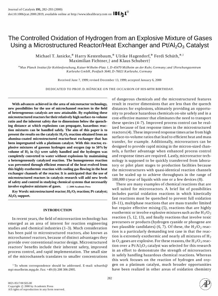
The microstructured reactor/heat exchanger used forthis work, shown in Fig. 1, was designed and built by theKarlsruhe Research Center (Forschungszentrum KarlsruheGmbH) (1, 19). The reactor is assembled from individualstainless steel plates with micromachined channels. Whenthe plates are stacked one on top of the other with a 90◦ rota-tion between each plate, two sets of perpendicular channelsare produced. The stack of plates is diffusion bonded to-gether, resulting in an essentially monolithic stainless steelassembly whose channels are vacuum tight and can alsohandle high pressures (1, 19). A stainless steel housingwith standard tube connections is welded onto the assem-bly to complete the reactor. For this particular reactor, twosets of foils with differently sized channels were used. Theset of larger channels (140× 200 µm), coated with Al2O3
and impregnated with Pt, are used for the H2/O2 reactionwhile the smaller channels (70× 100µm) function as a heatexchanger.
2. Alumina Deposition
The stainless steel microreactor/heat exchanger wascoated with alumina to increase the overall surface areaof the microchannels and to protect the surface fromreacting electrochemically with the hexachloroplatinicacid precursor solution necessary for the Pt catalyst. TheAl2O3 layer was grown on the reactor channels by an at-mospheric CVD process utilizing aluminum isopropoxide,Al[(CH3)2CHO]3, as the alumina precursor. The use ofaluminum isopropoxide, Al(OiPr)3, for the production ofaluminum oxide coatings has been described previously(20, 21) and for this work an experimental proceduresimilar to the earlier work by Aboaf was followed (22).Molten Al(OiPr)3 (m.p. 140◦C) was kept at a constanttemperature of 160◦C in a glass bubbler through which1.0 L/min of N2 was passed. This N2/Al(OiPr)3 was mixedwith O2 flowing at 7.0 L/min. Oxygen was necessary for thedecomposition of the alkoxide and to prevent the buildupof carbon in the reactor. Following mixing, the combi-nation of gases passed through the larger 140× 200 µmchannels in the reactor at 300◦C for 1 h, heated to 300◦C bypassing 7 L/min of preheated N2 through the set of smallermicrochannels (100× 70 µm). Additional heating could beobtained by placing external cartridge heaters in aluminumblocks above and below the reactor. Ceramic cloth wasused to insulate the reactor and maintain the elevatedtemperature. After 1 h, the reactor was cooled, and the flowdirection was reversed for a second 1-h period so that theentrance and exit of the reactor would have similar alumina
coatings. Note the coating system had to be operated forextended periods of time to work reliably. It was found
284 JANICKE ET AL.
FIG. 1. Photographs of the microstructured reactor developed and constructed by the Karlsruhe Research Center. Above is shown the reactor withand without the attached pipe fittings. A ruler in centimeters is included to show the scale. The bottom picture is a SEM micrograph showing a corner
view of the reactor. The larger channels (140× 200 µm) appear to be going into the darker face of the reactor with the smaller channels (70× 100 µm)running perpendicular.that after the deposition system was cleaned, growth rateswere rather small and inhomogeneous growth frequentlyoccurred, a fact which has been noted previously by other
research groups.After results showed that the microchannel reactor/heatexchanger performed differently depending on the amountand the nature of the platinum catalyst, it became evident
that further tests were necessary on a system in which the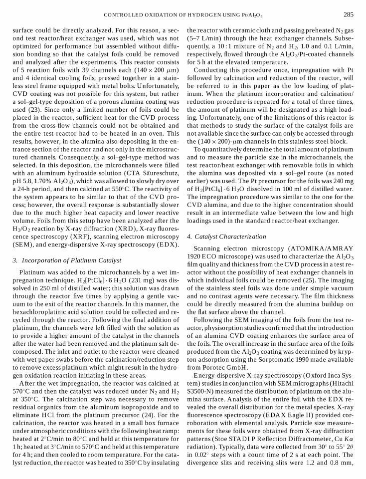
F
CONTROLLED OXIDATION Osurface could be directly analyzed. For this reason, a sec-ond test reactor/heat exchanger was used, which was notoptimized for performance but assembled without diffu-sion bonding so that the catalyst foils could be removedand analyzed after the experiments. This reactor consistsof 5 reaction foils with 39 channels each (140× 200 µm)and 4 identical cooling foils, pressed together in a stain-less steel frame equipped with metal bolts. Unfortunately,CVD coating was not possible for this system, but rathera sol–gel-type deposition of a porous alumina coating wasused (23). Since only a limited number of foils could beplaced in the reactor, sufficient heat for the CVD processfrom the cross-flow channels could not be obtained andthe entire test reactor had to be heated in an oven. Thisresults, however, in the alumina also depositing in the en-trance section of the reactor and not only in the microstruc-tured channels. Consequently, a sol–gel-type method wasselected. In this deposition, the microchannels were filledwith an aluminum hydroxide solution (CTA Saureschutz,pH 5.8, 1.70% Al2O3), which was allowed to slowly dry overa 24-h period, and then calcined at 550◦C. The reactivity ofthe system appears to be similar to that of the CVD pro-cess; however, the overall response is substantially slowerdue to the much higher heat capacity and lower reactivevolume. Foils from this setup have been analyzed after theH2/O2 reaction by X-ray diffraction (XRD), X-ray fluores-cence spectroscopy (XRF), scanning electron microscopy(SEM), and energy-dispersive X-ray spectroscopy (EDX).
3. Incorporation of Platinum Catalyst
Platinum was added to the microchannels by a wet im-pregnation technique. H2[PtCl6] · 6 H2O (231 mg) was dis-solved in 250 ml of distilled water; this solution was drawnthrough the reactor five times by applying a gentle vac-uum to the exit of the reactor channels. In this manner, thehexachloroplatinic acid solution could be collected and re-cycled through the reactor. Following the final addition ofplatinum, the channels were left filled with the solution asto provide a higher amount of the catalyst in the channelsafter the water had been removed and the platinum salt de-composed. The inlet and outlet to the reactor were cleanedwith wet paper swabs before the calcination/reduction stepto remove excess platinum which might result in the hydro-gen oxidation reaction initiating in these areas.
After the wet impregnation, the reactor was calcined at570◦C and then the catalyst was reduced under N2 and H2
at 350◦C. The calcination step was necessary to removeresidual organics from the aluminum isopropoxide and toeliminate HCl from the platinum precursor (24). For thecalcination, the reactor was heated in a small box furnaceunder atmospheric conditions with the following heat ramp:heated at 2◦C/min to 80◦C and held at this temperature for1 h; heated at 3◦C/min to 570◦C and held at this temperaturefor 4 h; and then cooled to room temperature. For the cata-
lyst reduction, the reactor was heated to 350◦C by insulatingHYDROGEN USING Pt/Al2O3 285
the reactor with ceramic cloth and passing preheated N2 gas(5–7 L/min) through the heat exchanger channels. Subse-quently, a 10 : 1 mixture of N2 and H2, 1.0 and 0.1 L/min,respectively, flowed through the Al2O3/Pt-coated channelsfor 5 h at the elevated temperature.
Conducting this procedure once, impregnation with Ptfollowed by calcination and reduction of the reactor, willbe referred to in this paper as the low loading of plat-inum. When the platinum incorporation and calcination/reduction procedure is repeated for a total of three times,the amount of platinum will be designated as a high load-ing. Unfortunately, one of the limitations of this reactor isthat methods to study the surface of the catalyst foils arenot available since the surface can only be accessed throughthe (140× 200)-µm channels in this stainless steel block.
To quantitatively determine the total amount of platinumand to measure the particle size in the microchannels, thetest reactor/heat exchanger with removable foils in whichthe alumina was deposited via a sol–gel route (as notedearlier) was used. The Pt precursor for the foils was 240 mgof H2[PtCl6] · 6 H2O dissolved in 100 ml of distilled water.The impregnation procedure was similar to the one for theCVD alumina, and due to the higher concentration shouldresult in an intermediate value between the low and highloadings used in the standard reactor/heat exchanger.
4. Catalyst Characterization
Scanning electron microscopy (ATOMIKA/AMRAY1920 ECO microscope) was used to characterize the Al2O3
film quality and thickness from the CVD process in a test re-actor without the possibility of heat exchanger channels inwhich individual foils could be removed (25). The imagingof the stainless steel foils was done under simple vacuumand no contrast agents were necessary. The film thicknesscould be directly measured from the alumina buildup onthe flat surface above the channel.
Following the SEM imaging of the foils from the test re-actor, physisorption studies confirmed that the introductionof an alumina CVD coating enhances the surface area ofthe foils. The overall increase in the surface area of the foilsproduced from the Al2O3 coating was determined by kryp-ton adsorption using the Sorptomatic 1990 made availablefrom Porotec GmbH.
Energy-dispersive X-ray spectroscopy (Oxford Inca Sys-tem) studies in conjunction with SEM micrographs (HitachiS3500-N) measured the distribution of platinum on the alu-mina surface. Analysis of the entire foil with the EDX re-vealed the overall distribution for the metal species. X-rayfluorescence spectroscopy (EDAX Eagle II) provided cor-roboration with elemental analysis. Particle size measure-ments for these foils were obtained from X-ray diffractionpatterns (Stoe STADI P Reflection Diffractometer, Cu Kαradiation). Typically, data were collected from 30◦ to 55◦ 2θin 0.02◦ steps with a count time of 2 s at each point. The
divergence slits and receiving slits were 1.2 and 0.8 mm,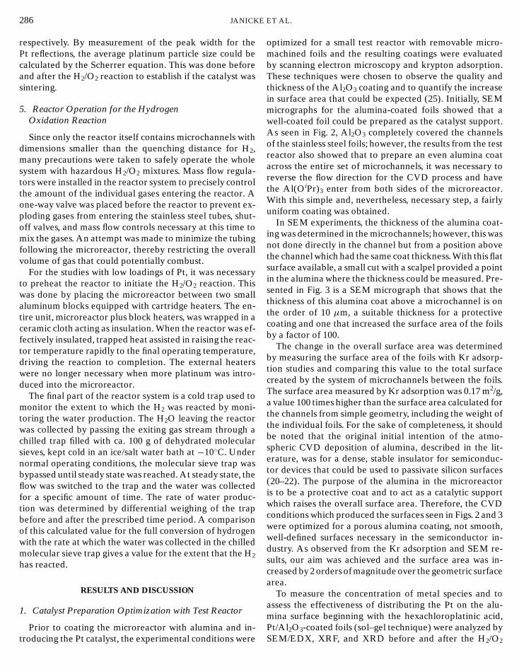
286 JANICKE
respectively. By measurement of the peak width for thePt reflections, the average platinum particle size could becalculated by the Scherrer equation. This was done beforeand after the H2/O2 reaction to establish if the catalyst wassintering.
5. Reactor Operation for the HydrogenOxidation Reaction
Since only the reactor itself contains microchannels withdimensions smaller than the quenching distance for H2,many precautions were taken to safely operate the wholesystem with hazardous H2/O2 mixtures. Mass flow regula-tors were installed in the reactor system to precisely controlthe amount of the individual gases entering the reactor. Aone-way valve was placed before the reactor to prevent ex-ploding gases from entering the stainless steel tubes, shut-off valves, and mass flow controls necessary at this time tomix the gases. An attempt was made to minimize the tubingfollowing the microreactor, thereby restricting the overallvolume of gas that could potentially combust.
For the studies with low loadings of Pt, it was necessaryto preheat the reactor to initiate the H2/O2 reaction. Thiswas done by placing the microreactor between two smallaluminum blocks equipped with cartridge heaters. The en-tire unit, microreactor plus block heaters, was wrapped in aceramic cloth acting as insulation. When the reactor was ef-fectively insulated, trapped heat assisted in raising the reac-tor temperature rapidly to the final operating temperature,driving the reaction to completion. The external heaterswere no longer necessary when more platinum was intro-duced into the microreactor.
The final part of the reactor system is a cold trap used tomonitor the extent to which the H2 was reacted by moni-toring the water production. The H2O leaving the reactorwas collected by passing the exiting gas stream through achilled trap filled with ca. 100 g of dehydrated molecularsieves, kept cold in an ice/salt water bath at −10◦C. Undernormal operating conditions, the molecular sieve trap wasbypassed until steady state was reached. At steady state, theflow was switched to the trap and the water was collectedfor a specific amount of time. The rate of water produc-tion was determined by differential weighing of the trapbefore and after the prescribed time period. A comparisonof this calculated value for the full conversion of hydrogenwith the rate at which the water was collected in the chilledmolecular sieve trap gives a value for the extent that the H2
has reacted.
RESULTS AND DISCUSSION
1. Catalyst Preparation Optimization with Test Reactor
Prior to coating the microreactor with alumina and in-troducing the Pt catalyst, the experimental conditions were
ET AL.
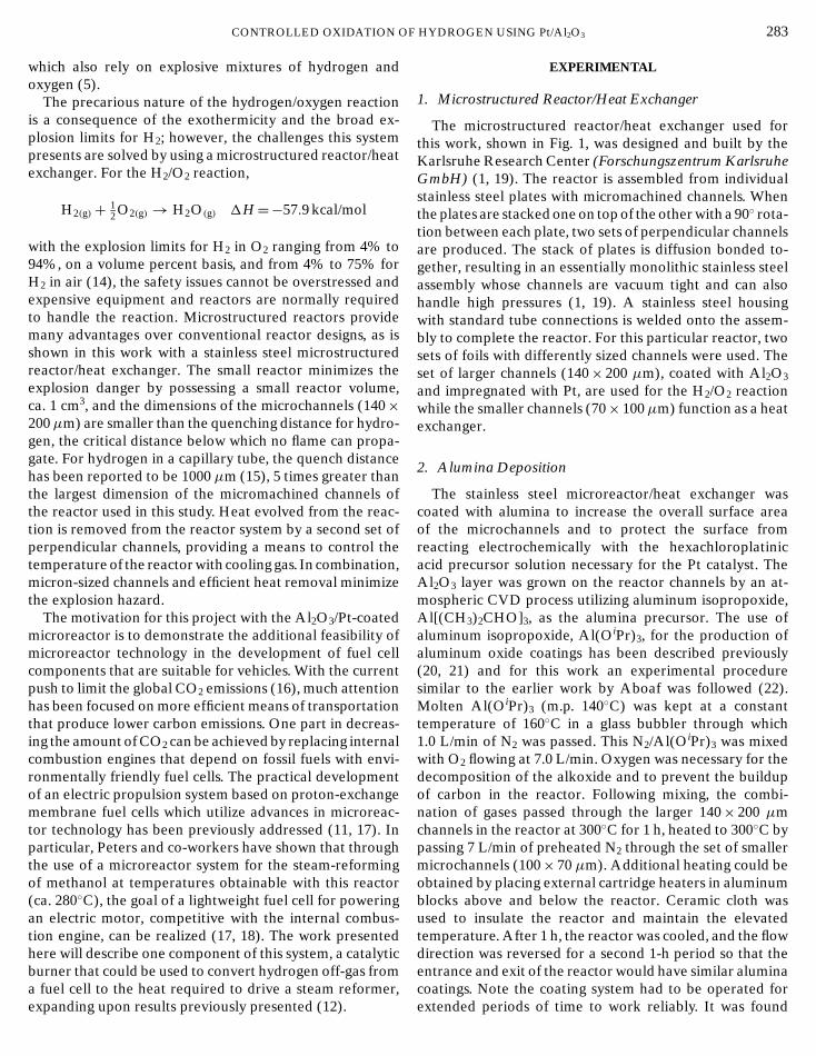
optimized for a small test reactor with removable micro-machined foils and the resulting coatings were evaluatedby scanning electron microscopy and krypton adsorption.These techniques were chosen to observe the quality andthickness of the Al2O3 coating and to quantify the increasein surface area that could be expected (25). Initially, SEMmicrographs for the alumina-coated foils showed that awell-coated foil could be prepared as the catalyst support.As seen in Fig. 2, Al2O3 completely covered the channelsof the stainless steel foils; however, the results from the testreactor also showed that to prepare an even alumina coatacross the entire set of microchannels, it was necessary toreverse the flow direction for the CVD process and havethe Al(OiPr)3 enter from both sides of the microreactor.With this simple and, nevertheless, necessary step, a fairlyuniform coating was obtained.
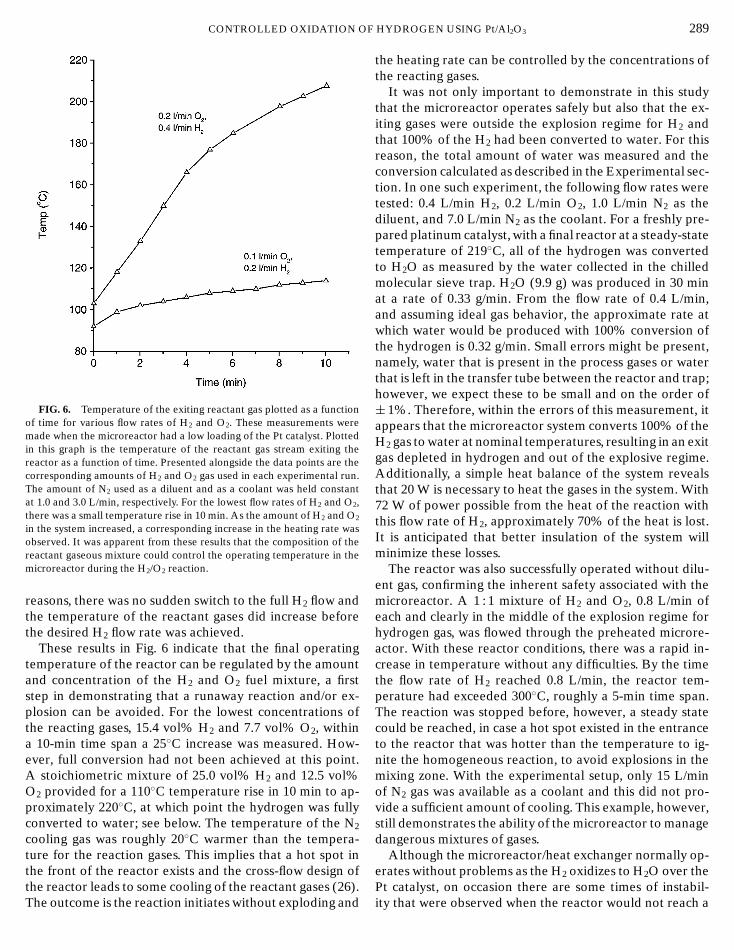
In SEM experiments, the thickness of the alumina coat-ing was determined in the microchannels; however, this wasnot done directly in the channel but from a position abovethe channel which had the same coat thickness. With this flatsurface available, a small cut with a scalpel provided a pointin the alumina where the thickness could be measured. Pre-sented in Fig. 3 is a SEM micrograph that shows that thethickness of this alumina coat above a microchannel is onthe order of 10 µm, a suitable thickness for a protectivecoating and one that increased the surface area of the foilsby a factor of 100.
The change in the overall surface area was determinedby measuring the surface area of the foils with Kr adsorp-tion studies and comparing this value to the total surfacecreated by the system of microchannels between the foils.The surface area measured by Kr adsorption was 0.17 m2/g,a value 100 times higher than the surface area calculated forthe channels from simple geometry, including the weight ofthe individual foils. For the sake of completeness, it shouldbe noted that the original initial intention of the atmo-spheric CVD deposition of alumina, described in the lit-erature, was for a dense, stable insulator for semiconduc-tor devices that could be used to passivate silicon surfaces(20–22). The purpose of the alumina in the microreactoris to be a protective coat and to act as a catalytic supportwhich raises the overall surface area. Therefore, the CVDconditions which produced the surfaces seen in Figs. 2 and 3were optimized for a porous alumina coating, not smooth,well-defined surfaces necessary in the semiconductor in-dustry. As observed from the Kr adsorption and SEM re-sults, our aim was achieved and the surface area was in-creased by 2 orders of magnitude over the geometric surfacearea.
To measure the concentration of metal species and toassess the effectiveness of distributing the Pt on the alu-mina surface beginning with the hexachloroplatinic acid,
Pt/Al2O3-coated foils (sol–gel technique) were analyzed bySEM/EDX, XRF, and XRD before and after the H2/O2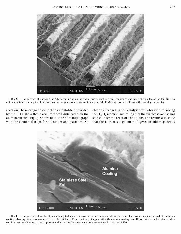
CONTROLLED OXIDATION OF HYDROGEN USING Pt/Al2O3 287
mn
FIG. 2. SEM micrograph showing the Al2O3 coating on an individualobtain a suitable coating, the flow direction for the gaseous mixture contai
reaction. The micrographs with the elemental data providedby the EDX show that platinum is well distributed on the
alumina surface (Fig. 4). Shown here is the SEM micrograph stable under the reaction conditions. The results also show with the elemental maps for aluminum and platinum. NoFIG. 3. SEM micrograph of the alumina deposited above a microchannel on an adjacent foil. A scalpel has produced a cut through the alumina
that the current sol–gel method gives an inhomogeneous
coating, allowing direct measurement of the film thickness. From the image iconfirm that the alumina coating is porous and increases the surface area of
icrostructured foil. The image was taken at the edge of the foil. Note toing the Al(OiPr)3 was reversed following the first deposition step.
obvious changes in the catalyst were observed followingthe H2/O2 reaction, indicating that the surface is robust and
t appears that the alumina coating is ca. 10-µm thick. Kr adsorption studiesthe channels by a factor of 100.

E
indicating it remains as an amorphous phase. No substantial differences are
288 JANICK
FIG. 4. SEM micrograph and EDX measurements showing an ele-mental map of the surface for one foil that has been coated with Al2O3
from a sol–gel and impregrated with platinum. From the SEM image, itcan be seen that the alumina has coated the channels, but some flaking andinhomogeneities have occurred. Below the micrograph are the EDX ele-mental maps with the lighter regions in the images representing the respec-tive elements. The lower left image is the Al measurement and reveals awell-dispersed alumina phase in the channels. The lower right image, the el-emental map for Pt, shows a nicely distributed metal phase as well. Nearlyidentical results were found for the foils following the H2/O2 reaction.
surface and some refinements are necessary for the tech-nique. One can actually expect the catalyst quality in theCVD-coated reactor to be better with respect to homogene-ity, as Fig. 2 shows. XRF spectroscopy confirmed that thesurface concentration did not change after operation andthe ratio of aluminum to platinum on an atomic percentagewas 99 : 1.
XRD was used to analyze the Pt particle size. As seen inthe XRD patterns, Fig. 5, Pt reflections occur at 39.8◦ and46.3◦ 2θ and reflections for the stainless steel are at 43.7◦
and 50.8◦ 2θ . For the XRD pattern of the foil following sev-eral runs of the H2/O2 reaction, no substantial differencesare observed, even though substantial improvement in thecatalytic performance was found. The particle size, as cal-culated by the Scherrer equation, was 15± 2 nm and doesnot change following the H2/O2 reaction. Therefore, there
does not appear to be sintering of the metal catalyst in thesystem under the experimental conditions reported hereET AL.
which would result in changes to the Pt metal particle size.In addition, no evidence for the formation of a bulk oxidephase could be detected with XRD.
2. Temperature Response for the Reactor/Heat Exchangerwith a Low Loading of Platinum
(All results reported in the following are for the diffusion-bonded reactor unless otherwise stated.) Initial experi-ments with the microreactor were conducted with a lowloading of platinum to test the safety of the Pt/Al2O3-coatedmicroreactor and to determine if the heat production fromthe H2/O2 reaction could be controlled with different fuelmixtures of O2 and H2. For this low amount of platinum,having impregnated the reactor with the hexachloroplatinicacid solution once, additional heaters maintained the reac-tor temperature at 80◦C, a sufficient temperature to initiatethe reaction. Displayed in Fig. 6 are plots showing the initialincrease in the temperature for the reactant gases exitingthe reactor for varying flow rates of H2 and O2 plotted as afunction of time. The flow rates of the reactant gases variedfrom 0.2 and 0.1 L/min to 0.4 and 0.2 L/min for H2 and O2,respectively. In each experiment, the amount of N2 in thesystem was constant, 1.0 L/min as a diluent for the H2/O2
mixture and 3.0 L/min for cooling in the second set of mi-crochannels. Note the first temperature points in Fig. 6 donot appear at 80◦C because the data have been recorded atthe time that the final H2 flow rate was reached. For safety
FIG. 5. XRD measurements of Pt/Al2O3-coated foil. Pt reflectionsoccur at 39.8◦C and 46.3◦ 2θ , and reflections from the stainless steel areobserved at 43.7◦C and 50.8◦ 2θ . Reflections from Al2O3 are not detected,
seen before and after the H2/O2 reaction and the Pt particle size remainsconstant at ca. 15± 2 nm.
F
CONTROLLED OXIDATION OFIG. 6. Temperature of the exiting reactant gas plotted as a functionof time for various flow rates of H2 and O2. These measurements weremade when the microreactor had a low loading of the Pt catalyst. Plottedin this graph is the temperature of the reactant gas stream exiting thereactor as a function of time. Presented alongside the data points are thecorresponding amounts of H2 and O2 gas used in each experimental run.The amount of N2 used as a diluent and as a coolant was held constantat 1.0 and 3.0 L/min, respectively. For the lowest flow rates of H2 and O2,there was a small temperature rise in 10 min. As the amount of H2 and O2
in the system increased, a corresponding increase in the heating rate wasobserved. It was apparent from these results that the composition of thereactant gaseous mixture could control the operating temperature in themicroreactor during the H2/O2 reaction.
reasons, there was no sudden switch to the full H2 flow andthe temperature of the reactant gases did increase beforethe desired H2 flow rate was achieved.
These results in Fig. 6 indicate that the final operatingtemperature of the reactor can be regulated by the amountand concentration of the H2 and O2 fuel mixture, a firststep in demonstrating that a runaway reaction and/or ex-plosion can be avoided. For the lowest concentrations ofthe reacting gases, 15.4 vol% H2 and 7.7 vol% O2, withina 10-min time span a 25◦C increase was measured. How-ever, full conversion had not been achieved at this point.A stoichiometric mixture of 25.0 vol% H2 and 12.5 vol%O2 provided for a 110◦C temperature rise in 10 min to ap-proximately 220◦C, at which point the hydrogen was fullyconverted to water; see below. The temperature of the N2
cooling gas was roughly 20◦C warmer than the tempera-ture for the reaction gases. This implies that a hot spot inthe front of the reactor exists and the cross-flow design of
the reactor leads to some cooling of the reactant gases (26).The outcome is the reaction initiates without exploding andHYDROGEN USING Pt/Al2O3 289
the heating rate can be controlled by the concentrations ofthe reacting gases.
It was not only important to demonstrate in this studythat the microreactor operates safely but also that the ex-iting gases were outside the explosion regime for H2 andthat 100% of the H2 had been converted to water. For thisreason, the total amount of water was measured and theconversion calculated as described in the Experimental sec-tion. In one such experiment, the following flow rates weretested: 0.4 L/min H2, 0.2 L/min O2, 1.0 L/min N2 as thediluent, and 7.0 L/min N2 as the coolant. For a freshly pre-pared platinum catalyst, with a final reactor at a steady-statetemperature of 219◦C, all of the hydrogen was convertedto H2O as measured by the water collected in the chilledmolecular sieve trap. H2O (9.9 g) was produced in 30 minat a rate of 0.33 g/min. From the flow rate of 0.4 L/min,and assuming ideal gas behavior, the approximate rate atwhich water would be produced with 100% conversion ofthe hydrogen is 0.32 g/min. Small errors might be present,namely, water that is present in the process gases or waterthat is left in the transfer tube between the reactor and trap;however, we expect these to be small and on the order of± 1%. Therefore, within the errors of this measurement, itappears that the microreactor system converts 100% of theH2 gas to water at nominal temperatures, resulting in an exitgas depleted in hydrogen and out of the explosive regime.Additionally, a simple heat balance of the system revealsthat 20 W is necessary to heat the gases in the system. With72 W of power possible from the heat of the reaction withthis flow rate of H2, approximately 70% of the heat is lost.It is anticipated that better insulation of the system willminimize these losses.
The reactor was also successfully operated without dilu-ent gas, confirming the inherent safety associated with themicroreactor. A 1 : 1 mixture of H2 and O2, 0.8 L/min ofeach and clearly in the middle of the explosion regime forhydrogen gas, was flowed through the preheated microre-actor. With these reactor conditions, there was a rapid in-crease in temperature without any difficulties. By the timethe flow rate of H2 reached 0.8 L/min, the reactor tem-perature had exceeded 300◦C, roughly a 5-min time span.The reaction was stopped before, however, a steady statecould be reached, in case a hot spot existed in the entranceto the reactor that was hotter than the temperature to ig-nite the homogeneous reaction, to avoid explosions in themixing zone. With the experimental setup, only 15 L/minof N2 gas was available as a coolant and this did not pro-vide a sufficient amount of cooling. This example, however,still demonstrates the ability of the microreactor to managedangerous mixtures of gases.
Although the microreactor/heat exchanger normally op-erates without problems as the H2 oxidizes to H2O over the
Pt catalyst, on occasion there are some times of instabil-ity that were observed when the reactor would not reach a
290 JANICKE
steady-state temperature. In initial trial experiments, the re-actor was coated with alumina, impregnated with platinum,tested in the reaction, and cleaned several times. Usually,the reactor performance proved to be reproducible; how-ever, when instabilities occurred with one coating, severalsmall explosions were observed. The only indications thatthey occurred were a quick popping sound; the gases brieflyceased to flow through the system, and oil from the bubbler(installed at the gas exit and used as a visual flow indi-cator) was drawn back toward the reactor at which pointthe reaction had stopped and the temperature of the reac-tor dropped to the original temperature determined by theheating blocks. After dry gases passed through the reactor,the reaction would begin again. The reason why this par-ticular coating led to instabilities could not be determinedsince the reactor cannot be disassembled. Obviously, thereaction did not initiate in the reactor channels but at theinlet or outlet of the system, perhaps due to an enrichmentof platinum in one of these areas, resulting from an errorduring the catalyst incorporation. The key point is, however,that the explosions were relatively harmless and might havegone unnoticed without assistance from the bubbler.
More stringent tests were done at the Fraunhofer In-stitute of Chemical Technology (FhG-ICT) where the mi-croreactor was tested for its ability to act as a flame resistor.In these experiments, a vessel of hydrogen was attached toone side of the reactor and a vessel of oxygen to the otherand the gases were allowed to diffuse between the two sidesthrough the reactor. An explosion was ignited on one sideof the reactor, but it could not pass through the microchan-nels to the other side, demonstrating the effectiveness of themicroreactor to stop the propagation of explosions with-out damaging the thin stainless steel plates (27). These twoexamples of explosions involving the microreactor/heat ex-changer, from research presented here and the results fromthe work at FhG-ICT, confirm that during such events ahigh level of safety is still maintained while in larger reac-tors such occurrences could be catastrophic.
3. Temperature Response for the Reactor/Heat Exchangerwith a High Loading of Platinum
Very promising results for the Pt/Al2O3-coated microre-actor were acquired after more platinum was incorporated.Namely, with repetition of the Pt impregnation and calci-nation/reduction step for a total of three times, the reactioninitiated at room temperature and external heaters wereno longer necessary. Shown in Fig. 7 are similar data as pre-sented earlier, the temperature of the reactant gases exitingthe reactor plotted as a function of time. For this series ofexperiments the flow rates of the N2 diluent, O2, and H2
are kept constant at 1.0, 0.2, and 0.4 L/min, respectively,with three runs having the N2 cooling gas set at 4.0, 5.0,
and 7.0 L/min. The quantity of N2 cooling gas was adjustedto show that the overall operating temperature can againET AL.
FIG. 7. Temperature response results for the microreactor with a highloading of platinum. Plotted in this graph is the temperature of the reactantgas stream exiting the reactor as a function of time. For each experimentthe flow rates of H2 and O2 were 0.4 and 0.2 L/min, respectively, and theamount of N2 as a diluent was 1.0 L/min. For the different experimentalruns the amount of N2 cooling gas was varied between 4.0 and 7.0 L/min,as shown in the plot. As with the previous results in Fig. 4, the data revealthat the final operating temperature of the reactor again can be controlled,in this case with the N2 cooling gas. For these results, however, no heatingfrom the external heaters was necessary and the reaction initiated at roomtemperature. The temperature of the cooling gases was ca. 20◦C higherthan the reaction gases.
be controlled. With the microreactor initially at room tem-perature, in all cases the temperature of the reactor slowlyincreased to 50◦C, at which point the reaction ignited andheated the reactor system to the final operating temper-atures. These temperatures were approximately 315, 280,and 230◦C for the respective N2 cooling gas rates of 4.0,5.0, and 7.0 L/min. It was found that the exiting cooling gastemperature again was approximately 20◦C hotter than theexiting reaction gases. Additionally, at these final operatingtemperatures there was in each experiment 100% conver-sion of the H2 to H2O and simple heat balances show that,of the 72 W of power possible, approximately 25 W wasused to heat the reactant and coolant gases. These encour-aging results differ from the earlier findings with the loweramount of Pt incorporated into the microreactor in that thereaction clearly initiates at room temperature, eliminatingthe need for external heaters, and the reactor functionedreliably without the instabilities experienced previously. Itshould also be mentioned that the composition of the reac-
tant gases for 1.0 L/min N2 and 0.2 L/min O2, excluding theH2, is roughly the same as dry air, 83% N2 and 17% O2 by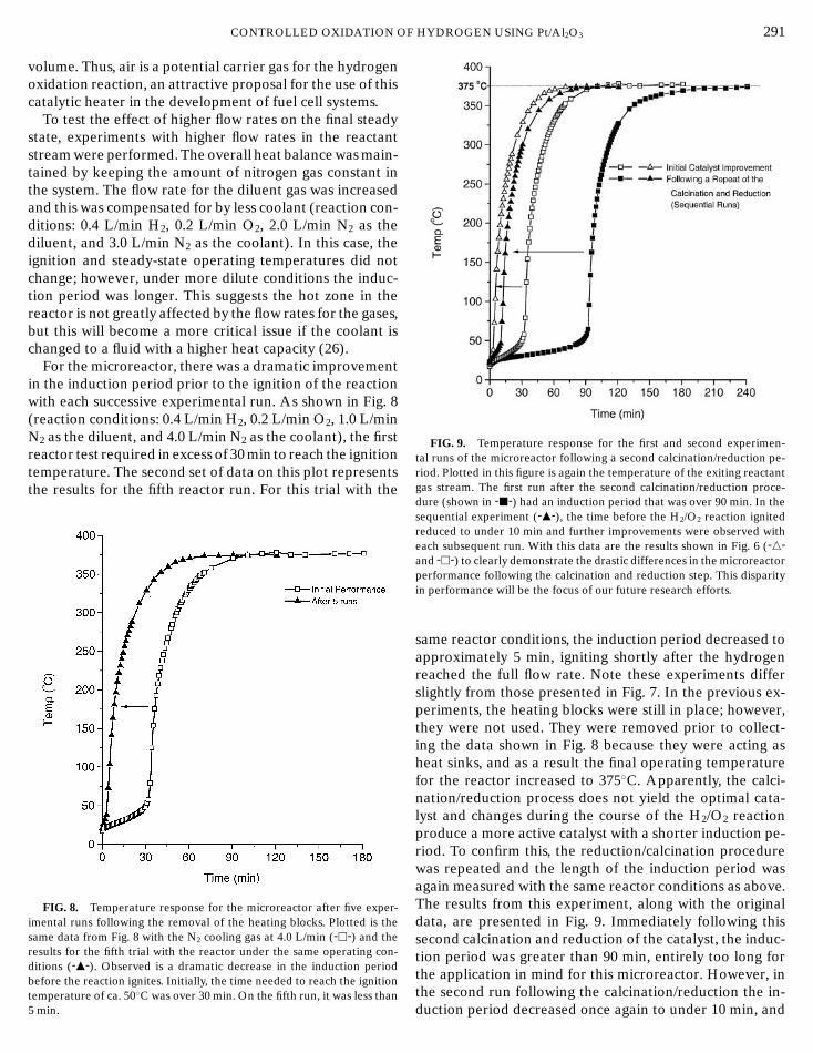
F
CONTROLLED OXIDATION Ovolume. Thus, air is a potential carrier gas for the hydrogenoxidation reaction, an attractive proposal for the use of thiscatalytic heater in the development of fuel cell systems.
To test the effect of higher flow rates on the final steadystate, experiments with higher flow rates in the reactantstream were performed. The overall heat balance was main-tained by keeping the amount of nitrogen gas constant inthe system. The flow rate for the diluent gas was increasedand this was compensated for by less coolant (reaction con-ditions: 0.4 L/min H2, 0.2 L/min O2, 2.0 L/min N2 as thediluent, and 3.0 L/min N2 as the coolant). In this case, theignition and steady-state operating temperatures did notchange; however, under more dilute conditions the induc-tion period was longer. This suggests the hot zone in thereactor is not greatly affected by the flow rates for the gases,but this will become a more critical issue if the coolant ischanged to a fluid with a higher heat capacity (26).
For the microreactor, there was a dramatic improvementin the induction period prior to the ignition of the reactionwith each successive experimental run. As shown in Fig. 8(reaction conditions: 0.4 L/min H2, 0.2 L/min O2, 1.0 L/minN2 as the diluent, and 4.0 L/min N2 as the coolant), the firstreactor test required in excess of 30 min to reach the ignitiontemperature. The second set of data on this plot representsthe results for the fifth reactor run. For this trial with the
FIG. 8. Temperature response for the microreactor after five exper-imental runs following the removal of the heating blocks. Plotted is thesame data from Fig. 8 with the N2 cooling gas at 4.0 L/min (-h-) and theresults for the fifth trial with the reactor under the same operating con-ditions (-m-). Observed is a dramatic decrease in the induction periodbefore the reaction ignites. Initially, the time needed to reach the ignition
temperature of ca. 50◦C was over 30 min. On the fifth run, it was less than5 min.HYDROGEN USING Pt/Al2O3 291
FIG. 9. Temperature response for the first and second experimen-tal runs of the microreactor following a second calcination/reduction pe-riod. Plotted in this figure is again the temperature of the exiting reactantgas stream. The first run after the second calcination/reduction proce-dure (shown in -j-) had an induction period that was over 90 min. In thesequential experiment (-m-), the time before the H2/O2 reaction ignitedreduced to under 10 min and further improvements were observed witheach subsequent run. With this data are the results shown in Fig. 6 (-n-and -h-) to clearly demonstrate the drastic differences in the microreactorperformance following the calcination and reduction step. This disparityin performance will be the focus of our future research efforts.
same reactor conditions, the induction period decreased toapproximately 5 min, igniting shortly after the hydrogenreached the full flow rate. Note these experiments differslightly from those presented in Fig. 7. In the previous ex-periments, the heating blocks were still in place; however,they were not used. They were removed prior to collect-ing the data shown in Fig. 8 because they were acting asheat sinks, and as a result the final operating temperaturefor the reactor increased to 375◦C. Apparently, the calci-nation/reduction process does not yield the optimal cata-lyst and changes during the course of the H2/O2 reactionproduce a more active catalyst with a shorter induction pe-riod. To confirm this, the reduction/calcination procedurewas repeated and the length of the induction period wasagain measured with the same reactor conditions as above.The results from this experiment, along with the originaldata, are presented in Fig. 9. Immediately following thissecond calcination and reduction of the catalyst, the induc-tion period was greater than 90 min, entirely too long forthe application in mind for this microreactor. However, in
the second run following the calcination/reduction the in-duction period decreased once again to under 10 min, and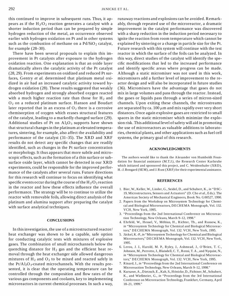
E
292 JANICKthis continued to improve in subsequent runs. Thus, it ap-pears as if the H2/O2 reaction generates a catalyst with ashorter induction period than can be prepared by simplehydrogen reduction of the metal, an occurrence observedearlier with hydrogen oxidation on Pt and in other systemssuch as the combustion of methane on a Pd/SiO2 catalyst,for example (28–30).
There have been several proposals to explain this im-provement in Pt catalysts after exposure to the hydrogenoxidation reaction. One explanation is that an oxide layerdramatically alters the catalytic activity of the Pt catalyst(28, 29). From experiments on oxidized and reduced Pt sur-faces, Gentry et al. determined that platinum metal oxi-dized in air had an increased catalytic activity toward hy-drogen oxidation (28). These results suggested that weaklyabsorbed hydrogen and strongly absorbed oxygen reactedwith a much higher reaction rate than those for H2 andO2 on a reduced platinum surface. Hanson and Boudartlater reported that in an excess of O2 there is a corrosivechemisorption of oxygen which erases structural featuresof the catalyst, leading to a markedly changed surface (29).Additional studies of Pt on Al2O3 supports have shownthat structural changes in the platinum at elevated tempera-tures, sintering, for example, also affect the availability andperformance of the catalyst (31–35). The XRD and XRFresults do not detect any specific changes that are readilyidentified, such as changes in the Pt surface concentrationor morphology. It thus appears that more subtle and micro-scopic effects, such as the formation of a thin surface or sub-surface oxide layer, which cannot be detected in our XRDexperiments, could be responsible for the improved perfor-mance of the catalysts after several runs. Future directionsfor this research will continue to focus on identifying whatspecific events occur during the course of the H2/O2 reactionin the reactor and how these effects influence the overallperformance. The strategy will be to continue to utilize thereactor with removable foils, allowing direct analysis of theplatinum and alumina support after preparing the catalystwith surface analytical techniques.
CONCLUSIONS
In this investigation, the use of a microstructured reactor/heat exchanger was shown to be a capable, safe optionfor conducting catalytic tests with mixtures of explosivegases. The combination of small microchannels below thequenching distance for H2 gas and the efficient heat re-moval through the heat exchanger side allowed dangerousmixtures of H2 and O2 to be mixed and reacted safely inthe Pt/Al2O3-coated microchannels. With the results pre-sented, it is clear that the operating temperature can becontrolled through the composition and flow rates of the
various gas components and coolants, key to implementingmicroreactors in current chemical processes. In such a way,ET AL.
runaway reactions and explosions can be avoided. Remark-ably, through repeated use of the microreactor, a dramaticimprovement in the catalyst performance was discoveredwith a sharp reduction in the induction period necessary toignite the reaction from room temperature which cannot beexplained by sintering or a change in particle size for the Pt.Future research with this system will continue with the testreactor in which the surface of the foils can be analyzed. Inthis way, direct studies of the catalyst will identify the spe-cific modifications that led to the increased performanceand identify specific areas where progress can be made.Although a static micromixer was not used in this work,micromixers add a further level of improvement to the re-actor design and will also be incorporated in future studies(36). Micromixers have the advantage that gases do notmix in large volumes and pass through the reactor. Instead,the gases or liquids pass through a series of micron-sizedchannels. Upon exiting these channels, the microstreamsare separated by ca. 100µm and mix rapidly over very shortdistances. Once again explosive gases are restricted to smallspaces in the static micromixer which minimize the explo-sion risk. This additional level of safety will aid in promotingthe use of microreactors as valuable additions to laborato-ries, chemical plants, and other applications such as fuel cellsystems, the primary goal of this research.
ACKNOWLEDGMENTS
The authors would like to thank the Alexander von Humboldt Foun-dation for financial assistance (M.T.J.), the Research Center Karlsruhewhich initiated and sponsored this project, and C. Weidenthaler (XRD),H.-J. Bongard (SEM), and J. Rust (XRF) for their experimental assistance.
REFERENCES
1. Bier, W., Keller, W., Linder, G., Seidel, D., and Schubert, K., in “DSC-19, Microstructures, Sensors and Actuators” (D. Cho et al., Eds.). TheAmerican Society of Mechanical Engineers, Book No. G00527, 1990.
2. Papers from the Workshop on Microsystem Technology for Chemi-cal and Biological Microreactors, DECHEMA Monograph, Vol. 132.VCH, New York, 1995.
3. “Proceedings from the 2nd International Conference on Microreac-tion Technology, New Orleans, March 9–12, 1998.”
4. Ehrfeld, W., Hessel, V., Mobius, H., Richter, Th., and Russow, K.,in “Microsystem Technology for Chemical and Biological Microreac-tors,” DECHEMA Monograph, Vol. 132. VCH, New York, 1995.
5. Jackel, K.-P., in “Microsystem Technology for Chemical and BiologicalMicroreactors,” DECHEMA Monograph, Vol. 132. VCH, New York,1995.
6. Lerou, J. J., Harold, M. P., Ryley, J., Ashmead, J., O’Brien, T. C.,Johnson, M., Perrotto, J., Blaisdell, C. T., Rensi, T. A., and Nyquist, N.,in “Microsystem Technology for Chemical and Biological Microreac-tors,” DECHEMA Monograph, Vol. 132. VCH, New York, 1995.
7. Rinard, I., in “Proceedings from the 2nd International Conference onMicroreaction Technology, New Orleans, March 9–12, 1998.”
8. Kursawe, A., Dietzsch, E., Kah, S., Honicke, D., Fichtner, M., Schubert,K., and Wießmeier, G., in “Proceedings from the 3rd International
Conference on Microreaction Technology, Frankfurt, Germany, April18–21, 1999.”
F
CONTROLLED OXIDATION O9. Honicke, D., and Wießmeier, G., in “Microsystem Technology forChemical and Biological Microreactors,” DECHEMA Monograph,Vol. 132. VCH, New York, 1995.
10. Srinivasan, R., Hsing, I.-M., Berger, P. E., Jensen, K. F., Firebaugh,S. L., Schmidt, M. A., Harold, M. P., Lerou, J. J., and Ryley, J. F.,AIChE J. 43, 3059 (1997).
11. Tonkovich, A. L. Y., Zilka, J. L., Powell, M. R., and Call, C. J., in “Pro-ceedings from the 2nd International Conference on MicroreactionTechnology, New Orleans, March 9–12, 1998.”
12. Hagendorf, U., Janicke, M., Schuth, F., Schubert, K., and Fichtner, M.,in “Proceedings from the 2nd International Conference on Microre-action Technology, New Orleans, March 9–12, 1998.”
13. Tonkovich, A. L. Y., Jimenez, D. M., Zilka, J. L., LaMont, M. J., Wang,Y., and Wegeng, R. S., in “Proceedings from the 2nd InternationalConference on Microreaction Technology, New Orleans, March 9–12,1998.”
14. Weast, R. C. (Ed.), “CRC Handbook of Chemistry and Physics,” 6thed., p. D-124. CRC Press, Inc., Boca Raton, FL, 1985.
15. This value was taken from an article by Gerhard, F., in “Ullmann’sEncyclopedia of Industrial Chemistry,” 5th ed., Vol. A18. VCHPublishers, New York, 1991. For detailed explanations and calcula-tions, see for example Bartknecht, W., “Explosionen-Ablauf undSchutzmaßnahmen.” Springer-Verlag, Berlin, 1980; Drell, I. L., andBelles, F. E., “Survey of Hydrogen Combustion Properties,” NACAReport 1383, 1958; Simon, D. M., Belles, F. E., and Spakowski,A. E., “Fourth Symposium (International) on Combustion,” pp. 126–138. The Reinhold Pub. Corp., Baltimore, 1953; Lewis, B., and vonElbe, G., “Combustion, Flames, and Explosions of Gases.” AcademicPress Inc., New York, 1951.
16. Berlin, B., Science 279, 330 (1998).17. Peters, R., Dusterwald, H. G., Hohlein, B., Meusinger, J., and
Stimming, U., “Scouting Study about the Use of Microreac-tors for Gas Supply in a PEM Fuel Cell System for Traction,”preprint.
18. Dusterwald, H. G., Hohlein, B., Kraut, H., Meusinger, J., Peters, R.,and Stimming, U., Chem. Eng. Technol. 20, 617 (1997).
HYDROGEN USING Pt/Al2O3 293
19. Schaller, Th., Bier, W., Linder, G., and Schubert, K., “Mechanis-che Mikrotechnik fur Abformwerkzeuge und Kleinserien,” ReportNo. FZKA 5670, pp. 45–50. Forschungszentrum Karlsruhe, Karlsruhe,Germany, 1995.
20. Saraie, J., Kwon, K., and Yodogawa, Y., J. Electrochem. Soc. 132, 890(1985).
21. Saraie, J., Ono, K., and Takeuchi, S., J. Electrochem. Soc. 136, 3139(1989).
22. Aboaf, J. A., J. Electrochem. Soc. 114, 948 (1967).23. See for example Narula, C. K., “Alumina Oxide Catalyst Supports
from Alumina Sols” U.S. Patent 5,210,062, 1993 and the referencestherein.
24. Barbier, J., Bahloul, D., and Marecot, P., J. Catal. 137, 377 (1992).25. Kestenbaum, H., Diplomarbeit, Johannes Wolfgang Goethe Uni-
versitat, Institut fur Anorganische Chemie, Frankfurt, Germany,Dec. 1997.
26. Janicke, M., Holzwarth, A., Fichtner, M., Schubert, K., and Schuth, F.,“A Microstructured Catalytic Reactor/Heat Exchanger for the Con-trolled Catalytic Reaction between H2 and O2” Stud. Surf. Sci. Catal.,in press.
27. Internal Report, Fraunhofer Institut fur Chemische Technologie, July1996.
28. Gentry, S. J., Firth, J. G., and Jones, A., J. Chem. Soc. Faraday Trans.70, 600 (1974).
29. Hanson, F. V., and Boudart, M., J. Catal. 53, 56 (1978).30. Pecchi, G., Reyes, P., Concha, I., and Fierro, J. L. G., J. Catal. 179, 309
(1998).31. Fiedorow, R. M. J., and Wanke, S. E., J. Catal. 43, 34 (1976).32. Dautzenberg, F. M., and Wolters, H. B. M., J. Catal. 51, 26 (1978).33. Den Otter, G. J., and Dautzenberg, F. M., J. Catal. 53, 116 (1978).34. Straguzzi, G. I., Aduriz, H. R., and Gigola, C. E., J. Catal. 66, 171
(1980).35. Sushumna, I., and Ruckenstein, E., J. Catal. 109, 433 (1988).36. Schubert, K., Bier, W., Brandner, J., Fichtner, M., Franz, C., and Linder,
G., “Proceedings from the 2nd International Conference on Microre-action Technology, New Orleans, March 9–12, 1998.”
Related Documents