Resonances in microstructured optical waveguides Natalia M. Litchinitser OFS Laboratories 25 Schoolhouse Road, Somerset, New Jersey 08873 [email protected] Steven C. Dunn OFS Specialty Photonics Division 25 Schoolhouse Road, Somerset, New Jersey 08873 Brian Usner University of Michigan, Ann Arbor, Michigan 48109 Benjamin J. Eggleton, Thomas P. White, Ross C. McPhedran, and C. Martijn de Sterke ARC Centre of Excellence for Ultrahigh-bandwidth Devices for Optical Systems (CUDOS), School of Physics, University of Sydney, NSW 2006 Australia Abstract: We propose a simple physical model that predicts the optical properties of a class of microstructured waveguides consisting of high-index inclusions that surround a low-index core. On the basis of this model, it is found that a large regime exists where transmission minima are determined by the geometry of the individual high-index inclusions. The locations of these minima are found to be largely unaffected by the relative position of the inclusions. As a result of this insight the difficult problem of analyzing the properties of complex structures can be reduced to the much simpler problem of analyzing the properties of an individual high-index inclusion in the structure. ©2002 Optical Society of America OCIS codes: (060.0060) Fiber optics and optical communications; (230.3990) Microstructure devices; (230.7370) Waveguides; (050.2230) Fabry-Perot References and links 1. J. C. Knight, J. Broeng, T. A. Birks, and P. St. J. Russell, “Photonic band gap guidance in optical fibers,” Science 282, 1476-1478 (1998). 2. P. Yeh, A. Yariv, and E. Marom, “Theory of Bragg fiber,” J. Opt. Soc. Am. 68, 1196-1201 (1978). 3. M. Ibanescu, Y. Fink, S. Fan, E. L. Thomas, and J. D. Joannopoulos, “An all-dielectric coaxial waveguide,” Science 289, 415-419 (2000). 4. B. J. Eggleton, C. Kerbage, P. S. Westbrook, R. S. Windeler, and A. Hale, “Microstructured optical fiber devices,” Opt. Express 9, 698-713 (2001), http://www.opticsexpress.org/abstract.cfm?URI=OPEX-9-13-698 5. T. F. Krauss and R. M. De La Rue, “Photonic crystals at optical wavelengths - past, present and future,” Prog. Quantum Electron. 23, 51-96 (1999). 6. R. F. Cregan, B. J. Mangan, J. C. Knight, T. A. Birks, P. St. J. Russell, P. J. Roberts, and D. C. Allan, “Single-mode photonic band gap guidance of light in air,” Science 285, 1537-1539 (1999). 7. R. T. Bise, R. S. Windeler, K. S. Kranz, C. Kerbage, B. J. Eggleton, and D. J. Trevor, “Tunable photonic band gap fiber,” in Optical Fiber Communication Conference, Vol. 70 of OSA Trends in Optics and Photonics Series, Technical Digest, Postconference Edition (Optical Society of America, Washington, D.C., 2002), pp. 466-468. 8. S. E. Barkou, J. Broeng, and A. Bjarklev, “Silica-air photonic crystal fiber design that permits waveguiding by a true photonic bandgap effect,” Opt. Lett. 24, 46 (1999). (C) 2003 OSA 19 May 2003 / Vol. 11, No. 10 / OPTICS EXPRESS 1243 #2398 - $15.00 US Received April 17, 2003; Revised May 11, 2003

Welcome message from author
This document is posted to help you gain knowledge. Please leave a comment to let me know what you think about it! Share it to your friends and learn new things together.
Transcript

Resonances in microstructured optical waveguides
Natalia M. Litchinitser OFS Laboratories
25 Schoolhouse Road, Somerset, New Jersey 08873 [email protected]
Steven C. Dunn OFS Specialty Photonics Division
25 Schoolhouse Road, Somerset, New Jersey 08873
Brian Usner University of Michigan, Ann Arbor, Michigan 48109
Benjamin J. Eggleton, Thomas P. White, Ross C. McPhedran, and C. Martijn de Sterke
ARC Centre of Excellence for Ultrahigh-bandwidth Devices for Optical Systems (CUDOS),
School of Physics, University of Sydney, NSW 2006 Australia
Abstract: We propose a simple physical model that predicts the optical properties of a class of microstructured waveguides consisting of high-index inclusions that surround a low-index core. On the basis of this model, it is found that a large regime exists where transmission minima are determined by the geometry of the individual high-index inclusions. The locations of these minima are found to be largely unaffected by the relative position of the inclusions. As a result of this insight the difficult problem of analyzing the properties of complex structures can be reduced to the much simpler problem of analyzing the properties of an individual high-index inclusion in the structure. ©2002 Optical Society of America OCIS codes: (060.0060) Fiber optics and optical communications; (230.3990) Microstructure devices; (230.7370) Waveguides; (050.2230) Fabry-Perot
References and links 1. J. C. Knight, J. Broeng, T. A. Birks, and P. St. J. Russell, “Photonic band gap guidance in optical fibers,”
Science 282, 1476-1478 (1998). 2. P. Yeh, A. Yariv, and E. Marom, “Theory of Bragg fiber,” J. Opt. Soc. Am. 68, 1196-1201 (1978). 3. M. Ibanescu, Y. Fink, S. Fan, E. L. Thomas, and J. D. Joannopoulos, “An all-dielectric coaxial waveguide,”
Science 289, 415-419 (2000). 4. B. J. Eggleton, C. Kerbage, P. S. Westbrook, R. S. Windeler, and A. Hale, “Microstructured optical fiber
devices,” Opt. Express 9, 698-713 (2001), http://www.opticsexpress.org/abstract.cfm?URI=OPEX-9-13-698 5. T. F. Krauss and R. M. De La Rue, “Photonic crystals at optical wavelengths - past, present and future,”
Prog. Quantum Electron. 23, 51-96 (1999). 6. R. F. Cregan, B. J. Mangan, J. C. Knight, T. A. Birks, P. St. J. Russell, P. J. Roberts, and D. C. Allan,
“Single-mode photonic band gap guidance of light in air,” Science 285, 1537-1539 (1999). 7. R. T. Bise, R. S. Windeler, K. S. Kranz, C. Kerbage, B. J. Eggleton, and D. J. Trevor, “Tunable photonic
band gap fiber,” in Optical Fiber Communication Conference, Vol. 70 of OSA Trends in Optics and Photonics Series, Technical Digest, Postconference Edition (Optical Society of America, Washington, D.C., 2002), pp. 466-468.
8. S. E. Barkou, J. Broeng, and A. Bjarklev, “Silica-air photonic crystal fiber design that permits waveguiding by a true photonic bandgap effect,” Opt. Lett. 24, 46 (1999).
(C) 2003 OSA 19 May 2003 / Vol. 11, No. 10 / OPTICS EXPRESS 1243#2398 - $15.00 US Received April 17, 2003; Revised May 11, 2003

9. R. Scarmozzino, A. Gopinath, R. Pregla, and S. Helfert, , “Numerical techniques for modeling guided-wave photonic devices,” IEEE J. Sel. Top. Quantum Electron. 6, 150-162 (2000).
10. T. P. White, B. T. Kuhlmey, R. C. McPhedran, D. Maystre, G. Renversez, C. Martijn de Sterke, and L. C. Botten, “Multipole method for microstructured optical fibers. I. Formulation,” J. Opt. Soc. Am. B 19, 2322-2330 (2002).
11. B. T. Kuhlmey, T. P. White, G. Renversez, D. Maystre, L. C. Botten, C. Martijn de Sterke, and R. C. McPhedran, “Multipole method for microstructured optical fibers. II. Implementation and results,” J. Opt. Soc. Am. B 19, 2331-2340 (2002).
12. M. A. Duguay, Y. Kukubun, T. L. Koch, and L. Pfeiffer, “Antiresonant reflecting optical waveguides in SiO2-Si multiplayer structures,” Appl. Phys. Lett. 49, 13-15 (1986).
13. T. Baba and Y. Kukubun, “Dispersion and radiation loss characteristics of antiresonant reflecting optical waveguides—numerical results and analytical expressions,” IEEE J. Quantum Electron. QE-28, 1689-1700 (1992).
14. N. M. Litchinitser, A. K. Abeeluck, C. Headley, and B. J. Eggleton, “Antiresonant reflecting photonic crystal optical waveguides,” Opt. Lett. 27, 1592-1594 (2002).
15. A. K. Abeeluck, N. M. Litchinitser, C. Headley, and B. J. Eggleton, “Analysis of spectral characteristics of photonic bandgap waveguides,” Opt. Express 10, 1320-1333 (2002), http://www.opticsexpress.org/abstract.cfm?URI=OPEX-10-23-1320
16. M. M. Z. Kharadly and J. E. Lewis, “Properties of dielectric-tube waveguides,” Proc. IEE 116, 214-224 (1969).
17. D. Marcuse and W. L. Mammel, “Tube waveguide for optical transmission,” Bell Syst. Tech. J. 52, 423-435 (1973).
18. T. P. White, R. C. McPhedran, C. Martijn de Sterke, N. M. Litchinitser, and B. J. Eggleton, “Resonance and scattering in microstructured optical fibers,” Opt. Lett. 27, 1977-1979 (2002).
19. J. A. Stratton, Electromagnetic Theory (McGraw-Hill, New York, 1941).
Microstructured optical waveguides are becoming of great importance in several emerging areas, including micrometer-scale novel photonic devices and integrated microcircuits [1-5]. One variant of these structures is the microstructured optical fiber (MOF), or holey fiber. These structures are essentially dielectric cylinders with multiple inclusions running along their lengths [6,7]. In these waveguides light is channeled through the core in one of two ways: total internal reflection (when the refractive index of the core is higher than that of the cladding), or coherent scattering from a microstructured cladding (typically when the refractive index of the core is lower than that of the cladding). The latter type can be subdivided into two categories: (1) waveguides with a solid core and high-index inclusions, and (2) those with air-core and air-holes.
A thorough characterization of an MOF (or any other waveguiding structure) involves describing many different features, including the transmission, dispersion, modal distribution, etc. Of these, the ability to predict transmission characteristics is essential, as it provides the location of high transmission regions and transmission minima, and is therefore helpful in the design of new waveguides and devices.
Most theoretical studies of light propagation in MOF structures were performed numerically [8-11], often via the widely used plane wave expansion method [8]. Although powerful, these direct numerical simulations do not always provide an understanding of the physical mechanisms behind the light propagation. In this paper we put forth a simple physical model for the optical properties of a class of microstructured waveguides consisting of high-index inclusions that surround a low index core shown in Fig. 1. These waveguides have been investigated by a number of research groups, who have shown that they exhibit several novel properties including periodic spectral responses, strong dispersion and tunability [7,12,13]. Of these, the ability to tune the transmission spectra is of particular interest, as it has strong potential in new devices such as tunable filters and dispersion compensators.
Models to describe the guiding properties of a few specific microstructured optical waveguides have been given previously. In Ref. [14] the properties of a class of one-dimensional planar or concentric ring waveguides were studied in the context of antiresonant reflections from multiple cladding layers. It was shown that the spectral properties of these
(C) 2003 OSA 19 May 2003 / Vol. 11, No. 10 / OPTICS EXPRESS 1244#2398 - $15.00 US Received April 17, 2003; Revised May 11, 2003

waveguides are principally determined by the index contrast and the thickness of the high-index layers, rather than by the lattice constant.
In this paper we present a general description of a class of microstructured fibers and waveguides with low index core and high index inclusions. We show that some of their important spectral properties can be described using a simple analytical formalism based on the normal modes of the high index inclusions. The formalism suggests that an important regime exists where the transmission minima of the entire waveguide structure are determined only by the geometry of individual high-index inclusions. As a result of this insight the complex and difficult problem of analyzing the propagation of light through the core can be reduced to the much simpler problem of analyzing the properties of an individual high-index inclusion. It should be noted that the structures described in Ref. [14] represent a subset of those to which the present analysis is applicable.
The structures under investigation in this work are: (a) a planar waveguide with a low-index (n1) core surrounded by alternating layers of high (n2) and low (n1) indices; (b) a concentric ring waveguide composed of layers of similar indices; and (c) a MOF with a low-index core surrounded by high-index (n2) cylindrical inclusions. These are shown below in Fig. 1 (a), (b), and (c) respectively.
Fig. 1. Microstructured optical waveguide geometries (n2 > n1 in all three cases).
For the analysis of planar and ring structures we will consider the location of the resonances in the transmission spectrum; the latter quantity being defined as T(λ) = Pout(λ)/Pin(λ), where Pin and Pout are the total powers in the core of the waveguide into which a Gaussian beam has been launched. The predictions are compared to numerical calculations of the transmission spectrum, which can be easily obtained using the beam propagation method or similar techniques [9,14,15].
In the model presented here, each high-index inclusion (layer) of the structure is considered as a waveguide that supports normal modes, along with their associated modal cutoff conditions. Modal cutoff corresponds to the wavelength at which the high-inxed inclusion switches from supporting n+1 modes to n modes. We show that minima in the transmission spectrum occur at these wavelengths. Care should be taken to differentiate between the two kinds of modes: low-index core modes and the modes of the high-index inclusions.
(a) (b) (c)
(C) 2003 OSA 19 May 2003 / Vol. 11, No. 10 / OPTICS EXPRESS 1245#2398 - $15.00 US Received April 17, 2003; Revised May 11, 2003
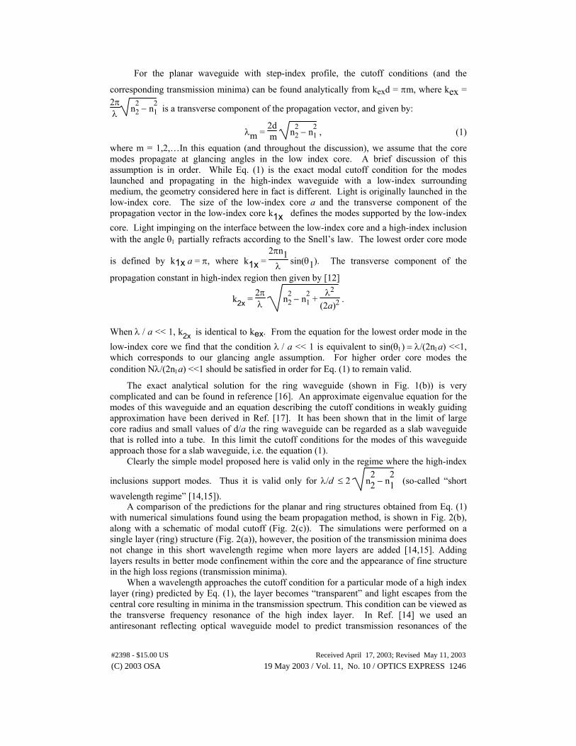
For the planar waveguide with step-index profile, the cutoff conditions (and the
corresponding transmission minima) can be found analytically from kexd = πm, where kex = 2πλ n2
2 − n21 is a transverse component of the propagation vector, and given by:
λm = 2d m n2
2 − n21 , (1)
where m = 1,2,…In this equation (and throughout the discussion), we assume that the core modes propagate at glancing angles in the low index core. A brief discussion of this assumption is in order. While Eq. (1) is the exact modal cutoff condition for the modes launched and propagating in the high-index waveguide with a low-index surrounding medium, the geometry considered here in fact is different. Light is originally launched in the low-index core. The size of the low-index core a and the transverse component of the propagation vector in the low-index core k1x defines the modes supported by the low-index core. Light impinging on the interface between the low-index core and a high-index inclusion with the angle θ1 partially refracts according to the Snell’s law. The lowest order core mode
is defined by k1x a = π, where k1x = 2πn1
λ sin(θ1). The transverse component of the
propagation constant in high-index region then given by [12]
k2x = 2πλ n2
2 − n21 +
λ2
(2a)2 .
When λ / a << 1, k2x is identical to kex. From the equation for the lowest order mode in the low-index core we find that the condition λ / a << 1 is equivalent to sin(θ1) = λ/(2n1a) <<1, which corresponds to our glancing angle assumption. For higher order core modes the condition Nλ/(2n1a) <<1 should be satisfied in order for Eq. (1) to remain valid.
The exact analytical solution for the ring waveguide (shown in Fig. 1(b)) is very complicated and can be found in reference [16]. An approximate eigenvalue equation for the modes of this waveguide and an equation describing the cutoff conditions in weakly guiding approximation have been derived in Ref. [17]. It has been shown that in the limit of large core radius and small values of d/a the ring waveguide can be regarded as a slab waveguide that is rolled into a tube. In this limit the cutoff conditions for the modes of this waveguide approach those for a slab waveguide, i.e. the equation (1).
Clearly the simple model proposed here is valid only in the regime where the high-index
inclusions support modes. Thus it is valid only for λ/d ≤ 2 n22 − n
21 (so-called “short
wavelength regime” [14,15]). A comparison of the predictions for the planar and ring structures obtained from Eq. (1)
with numerical simulations found using the beam propagation method, is shown in Fig. 2(b), along with a schematic of modal cutoff (Fig. 2(c)). The simulations were performed on a single layer (ring) structure (Fig. 2(a)), however, the position of the transmission minima does not change in this short wavelength regime when more layers are added [14,15]. Adding layers results in better mode confinement within the core and the appearance of fine structure in the high loss regions (transmission minima).
When a wavelength approaches the cutoff condition for a particular mode of a high index layer (ring) predicted by Eq. (1), the layer becomes “transparent” and light escapes from the central core resulting in minima in the transmission spectrum. This condition can be viewed as the transverse frequency resonance of the high index layer. In Ref. [14] we used an antiresonant reflecting optical waveguide model to predict transmission resonances of the
(C) 2003 OSA 19 May 2003 / Vol. 11, No. 10 / OPTICS EXPRESS 1246#2398 - $15.00 US Received April 17, 2003; Revised May 11, 2003

waveguides shown in Figs. 1(a) and 1(b). According to this model each layer in the multilayered cladding can be considered as a Fabry-Perot resonator. Narrow band resonances of this FP resonator correspond to transmission minima for the light propagating in the core, or “resonant” wavelengths of the low-index core waveguide. Wide antiresonances of the FP resonator correspond to a high transmission coefficient for the low-index core waveguide. In general, high transmission of the light in the low index core at a particular wavelength for a particular core mode can be guaranteed by proper choice of thicknesses of both high- and low-index layers such that they satisfy an antiresonant condition. The antiresonant condition for a high-index layer is given by kexd = π(2m+1)/2, m=0,1,2… and for a low-index layer by b = (2l+1)a/2, l=0,1,2… for fundamental core mode[12]. In the structures considered in this
Fig. 2. (a) Schematic of planar structure (n1=1.4, n2=1.8, d = 3.437µm), (b) calculated transmission spectra for planar and ring structure of length L=5cm, (c) analytical modal cutoff condition, and (d) absolute value of the electric field in high index layer (vertical straight lines show the borders of high index layer).
RING STRUCTURE PLANAR STRUCTURE
TRAN
SMIS
SIO
N
RING STRUCTURE PLANAR STRUCTURE
TRAN
SMIS
SIO
N
n
x
λ
n 1 n 2n 2
12
1110
98
7
RING STRUCTURE PLANAR STRUCTURE
TRAN
SMIS
SIO
N
RING STRUCTURE PLANAR STRUCTURE
TRAN
SMIS
SIO
N
n
x
Mod
e nu
mbe
r
λ
n 1 n 2n 2
12
1110
98
7
RING STRUCTURE PLANAR STRUCTURE
TRAN
SMIS
SIO
N
RING STRUCTURE PLANAR STRUCTURE
TRAN
SMIS
SIO
N
RING STRUCTURE PLANAR STRUCTURE
TRAN
SMIS
SIO
N
RING STRUCTURE PLANAR STRUCTURE
TRAN
SMIS
SIO
N
n
x
λ
n 1 n 2n 2
12
1110
98
7
RING STRUCTURE PLANAR STRUCTURE
TRAN
SMIS
SIO
N
RING STRUCTURE PLANAR STRUCTURE
TRAN
SMIS
SIO
N
RING STRUCTURE PLANAR STRUCTURE
TRAN
SMIS
SIO
N
RING STRUCTURE PLANAR STRUCTURE
TRAN
SMIS
SIO
N
n
x
Mod
e nu
mbe
r
λ
n 1 n 2n 2
12
1110
98
7
12
1110
98
7
λ=0.88µm λ=0.91µm λ=0.95µm
X (µm) X (µm) X (µm)
1 2 3 4 5 6 7 8 (<9)
1 2 3 4 5 6 7 8
1 2 3 4 5 6 7 (<8)λ=0.88µm λ=0.91µm λ=0.95µm
X (µm) X (µm) X (µm)
1 2 3 4 5 6 7 8 (<9)
1 2 3 4 5 6 7 8
1 2 3 4 5 6 7 (<8)
RING PLANAR RING STRUCTURE PLANAR STRUCTURE
TRAN
SMIS
SIO
N
RING STRUCTURE PLANAR STRUCTURE
TRAN
SMIS
SIO
N
n
x
λ
n 1 n 2n 2
12
1110
98
7
RING STRUCTURE PLANAR STRUCTURE
TRAN
SMIS
SIO
N
RING STRUCTURE PLANAR STRUCTURE
TRAN
SMIS
SIO
N
n
x
Mod
e nu
mbe
r
λ
n 1 n 2n 2
12
1110
98
7
RING STRUCTURE PLANAR STRUCTURE
TRAN
SMIS
SIO
N
RING STRUCTURE PLANAR STRUCTURE
TRAN
SMIS
SIO
N
RING STRUCTURE PLANAR STRUCTURE
TRAN
SMIS
SIO
N
RING STRUCTURE PLANAR STRUCTURE
TRAN
SMIS
SIO
N
n
x
λ
n 1 n 2n 2
12
1110
98
7
RING STRUCTURE PLANAR STRUCTURE
TRAN
SMIS
SIO
N
RING STRUCTURE PLANAR STRUCTURE
TRAN
SMIS
SIO
N
RING STRUCTURE PLANAR STRUCTURE
TRAN
SMIS
SIO
N
RING STRUCTURE PLANAR STRUCTURE
TRAN
SMIS
SIO
N
n
x
Mod
e nu
mbe
r
λ
n 1 n 2n 2
12
1110
98
7
12
1110
98
7
λ=0.88µm λ=0.91µm λ=0.95µm
X (µm) X (µm) X (µm)
1 2 3 4 5 6 7 8 (<9)
1 2 3 4 5 6 7 8
1 2 3 4 5 6 7 (<8)λ=0.88µm λ=0.91µm λ=0.95µm
X (µm) X (µm) X (µm)
1 2 3 4 5 6 7 8 (<9)
1 2 3 4 5 6 7 8
1 2 3 4 5 6 7 (<8)
RING PLANAR 1
0.8
0.6
0.4
0.2
0Tr
ansm
issi
on
(a) (b)
(c)
(d) λ
0.6 0.7 0.8λ (µm)
0.9 1
E
RING STRUCTURE PLANAR STRUCTURE
TRAN
SMIS
SIO
N
RING STRUCTURE PLANAR STRUCTURE
TRAN
SMIS
SIO
N
n
x
λ
n 1 n 2n 2
12
1110
98
7
RING STRUCTURE PLANAR STRUCTURE
TRAN
SMIS
SIO
N
RING STRUCTURE PLANAR STRUCTURE
TRAN
SMIS
SIO
N
n
x
Mod
e nu
mbe
r
λ
n 1 n 2n 2
12
1110
98
7
RING STRUCTURE PLANAR STRUCTURE
TRAN
SMIS
SIO
N
RING STRUCTURE PLANAR STRUCTURE
TRAN
SMIS
SIO
N
RING STRUCTURE PLANAR STRUCTURE
TRAN
SMIS
SIO
N
RING STRUCTURE PLANAR STRUCTURE
TRAN
SMIS
SIO
N
n
x
λ
n 1 n 2n 2
12
1110
98
7
RING STRUCTURE PLANAR STRUCTURE
TRAN
SMIS
SIO
N
RING STRUCTURE PLANAR STRUCTURE
TRAN
SMIS
SIO
N
RING STRUCTURE PLANAR STRUCTURE
TRAN
SMIS
SIO
N
RING STRUCTURE PLANAR STRUCTURE
TRAN
SMIS
SIO
N
n
x
Mod
e nu
mbe
r
λ
n 1 n 2n 2
12
1110
98
7
12
1110
98
7
λ=0.88µm λ=0.91µm λ=0.95µm
X (µm) X (µm) X (µm)
1 2 3 4 5 6 7 8 (<9)
1 2 3 4 5 6 7 8
1 2 3 4 5 6 7 (<8)λ=0.88µm λ=0.91µm λ=0.95µm
X (µm) X (µm) X (µm)
1 2 3 4 5 6 7 8 (<9)
1 2 3 4 5 6 7 8
1 2 3 4 5 6 7 (<8)
RING PLANAR RING STRUCTURE PLANAR STRUCTURE
TRAN
SMIS
SIO
N
RING STRUCTURE PLANAR STRUCTURE
TRAN
SMIS
SIO
N
n
x
λ
n 1 n 2n 2
12
1110
98
7
RING STRUCTURE PLANAR STRUCTURE
TRAN
SMIS
SIO
N
RING STRUCTURE PLANAR STRUCTURE
TRAN
SMIS
SIO
N
n
x
Mod
e nu
mbe
r
λ
n 1 n 2n 2
12
1110
98
7
RING STRUCTURE PLANAR STRUCTURE
TRAN
SMIS
SIO
N
RING STRUCTURE PLANAR STRUCTURE
TRAN
SMIS
SIO
N
RING STRUCTURE PLANAR STRUCTURE
TRAN
SMIS
SIO
N
RING STRUCTURE PLANAR STRUCTURE
TRAN
SMIS
SIO
N
n
x
λ
n 1 n 2n 2
12
1110
98
7
RING STRUCTURE PLANAR STRUCTURE
TRAN
SMIS
SIO
N
RING STRUCTURE PLANAR STRUCTURE
TRAN
SMIS
SIO
N
RING STRUCTURE PLANAR STRUCTURE
TRAN
SMIS
SIO
N
RING STRUCTURE PLANAR STRUCTURE
TRAN
SMIS
SIO
N
n
x
Mod
e nu
mbe
r
λ
n 1 n 2n 2
12
1110
98
7
12
1110
98
7
λ=0.88µm λ=0.91µm λ=0.95µm
X (µm) X (µm) X (µm)
1 2 3 4 5 6 7 8 (<9)
1 2 3 4 5 6 7 8
1 2 3 4 5 6 7 (<8)λ=0.88µm λ=0.91µm λ=0.95µm
X (µm) X (µm) X (µm)
1 2 3 4 5 6 7 8 (<9)
1 2 3 4 5 6 7 8
1 2 3 4 5 6 7 (<8)
RING PLANAR 1
0.8
0.6
0.4
0.2
0Tr
ansm
issi
on
RING STRUCTURE PLANAR STRUCTURE
TRAN
SMIS
SIO
N
RING STRUCTURE PLANAR STRUCTURE
TRAN
SMIS
SIO
N
n
x
λ
n 1 n 2n 2
12
1110
98
7
RING STRUCTURE PLANAR STRUCTURE
TRAN
SMIS
SIO
N
RING STRUCTURE PLANAR STRUCTURE
TRAN
SMIS
SIO
N
n
x
Mod
e nu
mbe
r
λ
n 1 n 2n 2
12
1110
98
7
RING STRUCTURE PLANAR STRUCTURE
TRAN
SMIS
SIO
N
RING STRUCTURE PLANAR STRUCTURE
TRAN
SMIS
SIO
N
RING STRUCTURE PLANAR STRUCTURE
TRAN
SMIS
SIO
N
RING STRUCTURE PLANAR STRUCTURE
TRAN
SMIS
SIO
N
n
x
λ
n 1 n 2n 2
12
1110
98
7
RING STRUCTURE PLANAR STRUCTURE
TRAN
SMIS
SIO
N
RING STRUCTURE PLANAR STRUCTURE
TRAN
SMIS
SIO
N
RING STRUCTURE PLANAR STRUCTURE
TRAN
SMIS
SIO
N
RING STRUCTURE PLANAR STRUCTURE
TRAN
SMIS
SIO
N
n
x
Mod
e nu
mbe
r
λ
n 1 n 2n 2
12
1110
98
7
12
1110
98
7
λ=0.88µm λ=0.91µm λ=0.95µm
X (µm) X (µm) X (µm)
1 2 3 4 5 6 7 8 (<9)
1 2 3 4 5 6 7 8
1 2 3 4 5 6 7 (<8)λ=0.88µm λ=0.91µm λ=0.95µm
X (µm) X (µm) X (µm)
1 2 3 4 5 6 7 8 (<9)
1 2 3 4 5 6 7 8
1 2 3 4 5 6 7 (<8)
RING PLANAR RING STRUCTURE PLANAR STRUCTURE
TRAN
SMIS
SIO
N
RING STRUCTURE PLANAR STRUCTURE
TRAN
SMIS
SIO
N
n
x
λ
n 1 n 2n 2
12
1110
98
7
RING STRUCTURE PLANAR STRUCTURE
TRAN
SMIS
SIO
N
RING STRUCTURE PLANAR STRUCTURE
TRAN
SMIS
SIO
N
n
x
Mod
e nu
mbe
r
λ
n 1 n 2n 2
12
1110
98
7
RING STRUCTURE PLANAR STRUCTURE
TRAN
SMIS
SIO
N
RING STRUCTURE PLANAR STRUCTURE
TRAN
SMIS
SIO
N
RING STRUCTURE PLANAR STRUCTURE
TRAN
SMIS
SIO
N
RING STRUCTURE PLANAR STRUCTURE
TRAN
SMIS
SIO
N
n
x
λ
n 1 n 2n 2
12
1110
98
7
RING STRUCTURE PLANAR STRUCTURE
TRAN
SMIS
SIO
N
RING STRUCTURE PLANAR STRUCTURE
TRAN
SMIS
SIO
N
RING STRUCTURE PLANAR STRUCTURE
TRAN
SMIS
SIO
N
RING STRUCTURE PLANAR STRUCTURE
TRAN
SMIS
SIO
N
n
x
Mod
e nu
mbe
r
λ
n 1 n 2n 2
12
1110
98
7
12
1110
98
7
λ=0.88µm λ=0.91µm λ=0.95µm
X (µm) X (µm) X (µm)
1 2 3 4 5 6 7 8 (<9)
1 2 3 4 5 6 7 8
1 2 3 4 5 6 7 (<8)λ=0.88µm λ=0.91µm λ=0.95µm
X (µm) X (µm) X (µm)
1 2 3 4 5 6 7 8 (<9)
1 2 3 4 5 6 7 8
1 2 3 4 5 6 7 (<8)
RING PLANAR 1
0.8
0.6
0.4
0.2
0Tr
ansm
issi
on
(a) (b)
(c)
(d) λ
0.6 0.7 0.8λ (µm)
0.9 1
E
(C) 2003 OSA 19 May 2003 / Vol. 11, No. 10 / OPTICS EXPRESS 1247#2398 - $15.00 US Received April 17, 2003; Revised May 11, 2003
paper b is typically less or equal a/2. This non-optimized thickness of low-index regions results in some fine structure in the high loss region in the vicinity of the transmission minima predicted by Eq. (1) and higher loss in “high transmission regions”. Throughout this paper we call the spectral regions between two minima “high transmission regions”, although the actual transmission may be not very high especially in single layer structures such as shown in Fig. 2(a).
Along with verifying the accuracy of our predictions for the transmission minima, Fig. 2(c) shows schematically that the excited modes of the high-index inclusions are predominantly of higher order. Since the refractive index of the core is lower than that of the inclusion, only the mode of the inclusion with effective refractive index closest to the refractive index of the core is phase matched. Figure 2(d) shows the evolution of oscillations in the high index layer (inclusion) for the wavelengths just above the resonance, in the middle of high transmission region, and just before the next resonance. The number of oscillations gradually evolves from eight to seven as the wavelength crosses one transmission region.
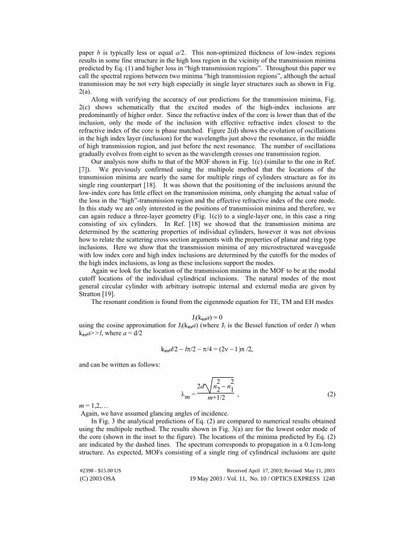
Our analysis now shifts to that of the MOF shown in Fig. 1(c) (similar to the one in Ref. [7]). We previously confirmed using the multipole method that the locations of the transmission minima are nearly the same for multiple rings of cylinders structure as for its single ring counterpart [18]. It was shown that the positioning of the inclusions around the low-index core has little effect on the transmission minima, only changing the actual value of the loss in the “high”-transmission region and the effective refractive index of the core mode. In this study we are only interested in the positions of transmission minima and therefore, we can again reduce a three-layer geometry (Fig. 1(c)) to a single-layer one, in this case a ring consisting of six cylinders. In Ref. [18] we showed that the transmission minima are determined by the scattering properties of individual cylinders, however it was not obvious how to relate the scattering cross section arguments with the properties of planar and ring type inclusions. Here we show that the transmission minima of any microstructured waveguide with low index core and high index inclusions are determined by the cutoffs for the modes of the high index inclusions, as long as these inclusions support the modes.
Again we look for the location of the transmission minima in the MOF to be at the modal cutoff locations of the individual cylindrical inclusions. The natural modes of the most general circular cylinder with arbitrary isotropic internal and external media are given by Stratton [19].
The resonant condition is found from the eigenmode equation for TE, TM and EH modes
Jl(kexa) = 0 using the cosine approximation for Jl(kexa) (where Jl is the Bessel function of order l) when kexa>>l, where a = d/2
kexd/2 − lπ/2 − π/4 = (2ν − 1)π /2, and can be written as follows:
λm = 2d n
22 − n
21
m+1/2 , (2)
m = 1,2,… Again, we have assumed glancing angles of incidence.
In Fig. 3 the analytical predictions of Eq. (2) are compared to numerical results obtained using the multipole method. The results shown in Fig. 3(a) are for the lowest order mode of the core (shown in the inset to the figure). The locations of the minima predicted by Eq. (2) are indicated by the dashed lines. The spectrum corresponds to propagation in a 0.1cm-long structure. As expected, MOFs consisting of a single ring of cylindrical inclusions are quite
(C) 2003 OSA 19 May 2003 / Vol. 11, No. 10 / OPTICS EXPRESS 1248#2398 - $15.00 US Received April 17, 2003; Revised May 11, 2003

lossy even at the wavelengths far from resonance. Light leakage between the inclusions contributes to this loss. The accuracy of the analytical model was also verified by comparing the resonant wavelengths for different cylinder radii (obtained through numerical simulation) to those predicted by the model. This is shown in Fig. 3(b). This figure shows a fine structure within the high loss regions even for a single ring of high index inclusions. Part (c) of the figure shows the resulting modal structure (longitudinal part of the Poynting vector Sz) in the inclusions, while the transverse cross-sections of Sz for wavelengths above and below the resonance are given in Fig. 3(d). Again, these figures confirm that the (n+1)th mode transfers into the nth mode as the wavelength passes the transmission minimum.
It should be noted, that if we compare the resonant wavelengths obtained from Eqs. (1) and (2) for the same parameter d (see Fig. 1), we find that resonant wavelengths of the MOF with cylindrical inclusions are out-of-phase with those of the planar structures for the same d, n1, and n2. This means that wavelengths of minimum transmission in planar structures have high transmission in MOFs. This result follows from the cutoff (resonant) conditions (1) and (2) that can be written as kexd = mπ and kexd = (m+1/2)π respectively, where m is an integer number.
While closed-form analytical solutions for the modal cutoff can be found in a limited number of cases, we can always predict the cutoff wavelengths for other geometries of the high index inclusions numerically. Therefore, this study suggests that using the present approach transmission minima of any microstructured waveguide with low index core and high index inclusions of arbitrary shape can be found, as long as each inclusion forms a waveguide.
In summary, we found that a large regime exists where the positions of transmission minima of microstructured optical waveguides with low-index core and high-index inclusions can be found by calculating the cut-off wavelength for the modes of high-index regions, and thus depend only on the mode structure of those inclusions. The complex problem of analyzing the properties of complex microstructured waveguides is thereby reduced to the much simpler problem of analyzing an individual high-index inclusion. Analytical predictions were confirmed by numerical simulations.
This work was produced with the assistance of the Australian Research Council under the ARC Centre of Excellence program.
(C) 2003 OSA 19 May 2003 / Vol. 11, No. 10 / OPTICS EXPRESS 1249#2398 - $15.00 US Received April 17, 2003; Revised May 11, 2003

Fig. 3. Continued on next page.
(C) 2003 OSA 19 May 2003 / Vol. 11, No. 10 / OPTICS EXPRESS 1250#2398 - $15.00 US Received April 17, 2003; Revised May 11, 2003

Fig. 3. (a) Transmission spectrum for fundamental mode of MOF shown in the inset (n1=1.44, n2=1.8, d=3.8µm). Straight dashed lines show analytical predictions (from Eq. (2)) for resonant wavelengths. (b) Analytical versus numerical predictions for resonant wavelengths for different d. (c) Longitudinal component of the Poynting vector Sz, and (d) Sz along X axis for two wavelengths. Straight dashed lines show the position of the high-index inclusion.
Sz
−8 −6 −4 −2 0 2 4 6 8
Sz
X (µm)
λ = 0.825µm
λ = 0.75µmSz
−8 −6 −4 −2 0 2 4 6 8
Sz
X (µm)
λ = 0.825µm
λ = 0.75µm
(d)
(C) 2003 OSA 19 May 2003 / Vol. 11, No. 10 / OPTICS EXPRESS 1251#2398 - $15.00 US Received April 17, 2003; Revised May 11, 2003
Related Documents