The CKOV support By P Lau

The CKOV support By P Lau. Hall space available to the Ckov & TOF 0 Beam line 3.
Dec 21, 2015
Welcome message from author
This document is posted to help you gain knowledge. Please leave a comment to let me know what you think about it! Share it to your friends and learn new things together.
Transcript
The CKOV support
By P Lau
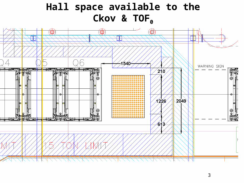
Hall space available to the Ckov & TOF0
Beam line
3

10
Space take up for the combined Cherenkov & TOF0

Requirements1. Accessibility for maintenance for both CKOV1 and TOF0 on both sides of the beam line
2. Vertical and transverse remote adjustments to center on the beam
Typically ~ +/- 5 cm horizontally and vertically
3. As much longitudinal free space as possible for safety purposes (rescue via crane in case of emergency)
Proposal from meeting (PD, WL, GG) at RAL on May 3-4
Movable platform + 10 /- 30 cm horizontally
+/- 5 cm vertically
Max load = 1 ton 4

2 proposals for CKOV support
Proposal A• Table size 1,820 (W) mm x
1,010 (D) mm
Proposal B• Table size is 1,400 (W) mm x
1,120 (D) mm

Proposal A - Isotropic View

Proposal A - The left most position in X direction
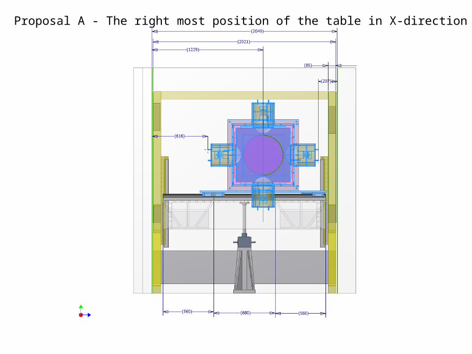
Proposal A - The right most position of the table in X-direction

Proposal A - End View

Proposal A – The Top View

Proposal B- Isotropic View
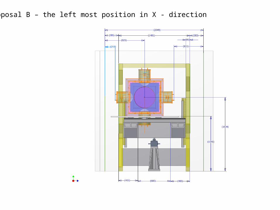
Proposal B – the left most position in X - direction

Proposal B- the right most position in X - direction
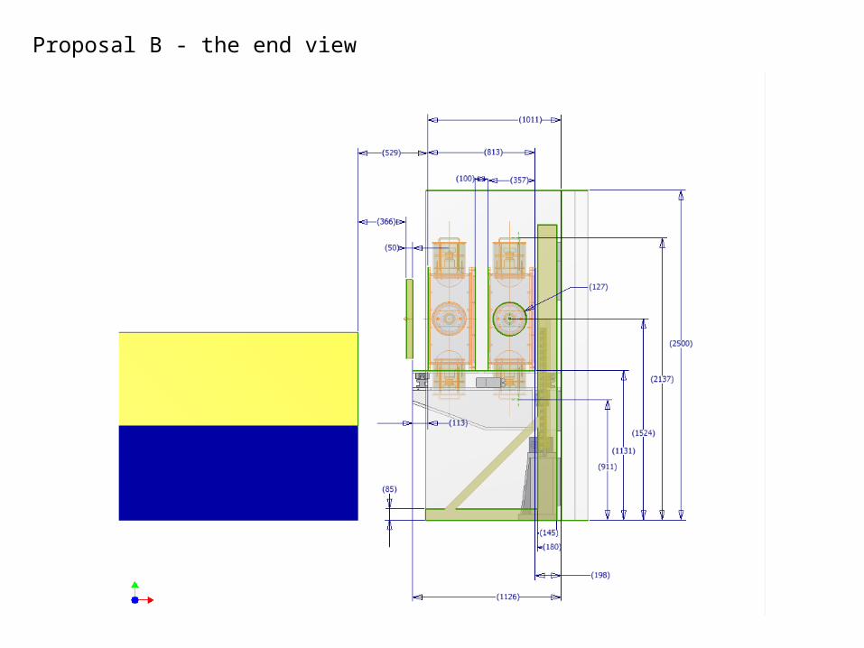
Proposal B - the end view
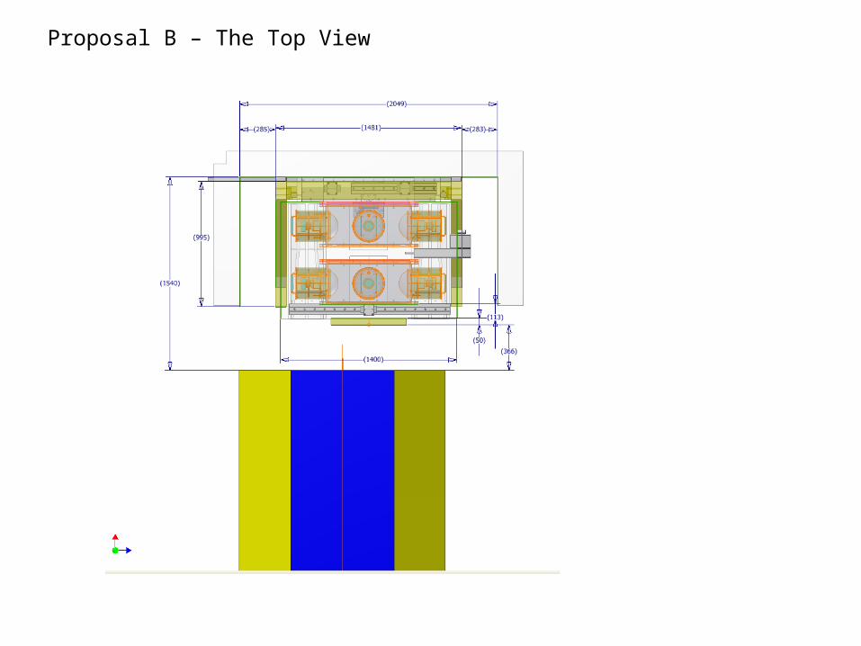
Proposal B – The Top View

Comment on Proposal A and B
1. More material, heavier in weight
2. No walk way between the wall shield and CKOV support
3. No one could get into the CKOV support area, can be argued as preventive from accident inside the CKOV support
4. Distance between the tracker and the front side of TOF0 is 405 mm
1. Less material
2. About 280 mm gap between the shield wall and CKOV support
3. In case of anyone falls down inside the CKOV support area, should have enough space to get him/her out
4. Distance between the tracker and the front side of TOF0 is 366 mm
Related Documents