VOL. XV FEBRUARY, 1928 No. 2 THE BROWN BOVERI REVI EW EDITED BY BROWN, BOVERI & COMPANY, LIMITED, BADEN (SWITZERLAND) ACCIAIERIE ELETTRICHE COGNE-GIROD, S. A., AOSTA (ITALY). Brown Boveri steel smelting - furnace with a capacity of 20 tons. CONTENTS: PAGE The single-phase express locomotive type 2 D 0 1 with Brown Boveri individual axle drive . . . 63 The parallel Operation of generating stations . 73 Brown Boveri tube-mill drives 83 Direct-current pressure Converter for supplying- constant secondary pressure from variable prim- ary pressure 89 PAGE Notes: Electrical steel furnaces for capacities of 20 tons 93 The Brown Boveri method of fastening- measuring wires in switchboards 93 The electric locomotives for the Oslo Lilleström Railway 94

Welcome message from author
This document is posted to help you gain knowledge. Please leave a comment to let me know what you think about it! Share it to your friends and learn new things together.
Transcript

VOL. XV FEBRUARY, 1928 No. 2
THE BROWN BOVERI REVI EW
EDITED B Y BROWN, BOVERI & COMPANY, LIMITED, BADEN ( S W I T Z E R L A N D )
ACCIAIERIE ELETTRICHE COGNE-GIROD, S. A., AOSTA (ITALY).
Brown Boveri steel smelting- furnace with a capacity of 20 tons.
C O N T E N T S : PAGE
The single-phase express locomotive type 2 D 0 1 with Brown Boveri individual axle drive . . . 63
The parallel Operation of generating stations . 73 Brown Boveri tube-mill drives 83 Direct-current pressure Converter for supplying-
constant secondary pressure from variable prim-ary pressure 89
PAGE Notes: Electrical steel furnaces for capacities of
20 tons 93 The Brown Boveri method of fastening- measuring
wires in switchboards 93 The electric locomotives for the Oslo Lilleström
Railway 94

BROWN BOVERI SHIPS' MACHINERY
SUPERCHARGING B L O W E R DRIVEN BY AN EXHAUST-GAS TURBINE FOR INCREASING THE OUTPUT OF FOUR-STROKE DIESEL ENGINES.
MARINE TURBINES WITH REDUCTION GEARS TURBO-LIGHTING SETS
TURBO-BLOWERS FOR FORCED DRAUGHT SCAVENGING AND SUPERCHARGING
BLOWERS FOR MARINE DIESEL ENGINES ELECTRICAL EQUIPMENT FOR DECK
AUXILIARIES
THE BROWN BOVERI REVIEW THE HOUSE JOURNAL OF BROWN, BOVERI & COMPANY, LIMITED, BADEN (SWITZERLAND)
VOL. XV FEBRUARY, 1928 No. 2 The Brown Boveri Review is issued monthly. Single numbers: 1.20 francs (1 Shilling). Annual subscription: 12 francs (10 shillings), postage and packing extra.
Reproduction of articles or illustrations is permitted subject to füll acknowledgment.
THE SINGLE-PHASE EXPRESS LOCOMOTIVE TYPE 2 D0 1 WITH BROWN BOVERI INDIVIDUAL AXLE DRIVE.
General. A modification in the method of class-ifying locomotives, as usually employed in the Brown Boveri Review, has been introduced in this article, consisting in the addition of the letter o after the D to signify individually-driven, i. e., non-coupled axles. Since the individual axle drive was introduced, loco-motives of
this type have also
been desig-nated by the
symbol 2 -AAAA-l or 2 - A 4 - 1 . The new me-thod employ-
ed in the present ar-ticle is not only more convenient
in speaking and writing but is also better adapt-ed for use
l • M i m'mmSm
in conjunc-tion with the universally accepted designations for locomotives with rod drives. With the continually increasing number of locomotives with individual axle drives the necessity for a special symbol for this type of drive will probably become less urgent, and it is therefore advisable to retain the designation 2 D 1, with the addition, for the present, of an o after the D. In actual practice it is more important to know the number of driving axles,
Decimal index 621. 334. 2.
the method of power transmission being a secondary consideration. Moreover, on the railways themselves the wheel arrangement is generally not included in the designation, an indication of the maximum per-missible speed of the locomotive in question being given the preference. For example, the locomotive
described in the present
article is designated
Ae 4/7 by the Swiss
Federal Rail-ways, the
character A showing that
the maxi-mum running
speed is ninety kilo-metres an hourormore,
and the numerals denoting
that the total number of
axles is
• > mm
Express locomotive type 2 D o 1 with Brown Boveri individual axle drive for the Swiss Federal Railways.
seven, of which four are driving axles. Moreover, as the character e indicates an electric locomotive, the designation provides the railway staff with füll Inform-ation as to the maximum speed, class of locomotive, adhesion conditions, and running characteristics.
For locomotive designers, however, the designation 2 D 0 1 is to be preferred, since it at once shows the general arrangement of the locomotive running gear.
PAGE 64 THE BROWN BOVERI REVIEW FEBRUARY, 1928
When the electrification of the Swiss Federal Railways was being planned there was practically no alternative to either side-rod locomotives or locomo-tives with tram-type motors for express Service. At the present time the Orders placed by the Swiss Federal Railways include 236 express locomotives, most of which are in Service, and of these only 60 have side-rod drive; there are no locomotives with tram-type motors. These figures show how quickly this, for Europe, novel method of transmission has been developed in Switzerland. Although the idea of transmitting the rotational movement of the motor direct to the driving wheels without the intervention of cranks and rods is not new, suitable designs for the transmission of large powers have hitherto been lacking.
One of the manifold advantages of the individual drive system is the possibility of using the same main components for locomotives of both large and small power. This is shown very clearly in the case of the 2 D 0 1 express locomotives ordered from Brown, Boveri & Co. by the Swiss Federal Railways. These new locomotives differ from the Brown Boveri 2 C„ 1 locomotives with individual axle drive' chiefly in the addition of a fourth individually driven axle. The transmission gear for the driving "axles is similar in both cases and the traction motors are identical in design and Output.
The locomotive underframe and body were re-quired to be suitably lengthened without making any fundamental changes in design, and the only modifi-cation to the electrical equipment was the necessary increase in the rating of the transformer and switchgear.
Although the 2 C 0 1 locomotives have proved capable of dealing with the greater part of the express service, the administration desired to possess an express locomotive of still greater power and adhesive weight for hauling heavy through trains. The use of these heavier locomotives will enable an extra or banking locomotive to be dispensed with in many cases.
The 2 D 0 1 locomotives will be capable of haul-ing a trailing load of 600 tons up a gradient of 0 • 2 °/o at a speed of 90 kilometres per hour. On a gradient of 1 • 2 °/o the speed is to be 65 kilometres per hour with the same trailing load. If the locomotive is used on mountain sections the trailing load should be 360 tons for speeds of 65 kilometres per hour.
1 The Brown Boveri Review, 1922, No. 5.
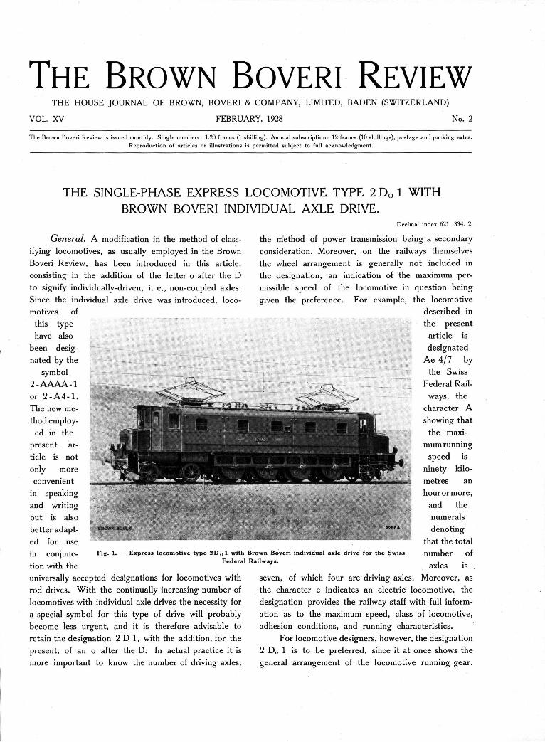
Mechanical part. The arrangement of two gangways running the whole length of the locomotive had already been abandoned in the case of the 2 C 0 1 express locomotives without impairing the accessibility of the equipment. On the contrary, the motor com-partment is roomy and pleasing in appearance. Most important of all, however, is the possibility of balan-cing the weight of the one-sided driving gear by this means.
The body of the locomotive is of the same height throughout, both for the motor compartment and for the two driving cabs, and is provided with two small hoods. It is divided into three parts, thus facilitating access to the machinery during erection and over-hauling. The body rests on two 28-mm longitudinal frame members.
In all the 2 C 0 1 locomotives owned by the Swiss Federal Railways, the supporting structure for the drive comprises a suitably reinforced dish-shaped framework which is built up as a separate element for each drive and secured to the main frame of the locomotive. In the case of the 2 D 0 1 locomotives these separate elements are combined in the cast-steel frame member enclosing the four driving wheels. This frame member is in turn bolted to the frame of the locomotive, for which it provides additional stiffening.' The continuous cast-steel member carries the journals for the gear wheels. The casings for the gear wheels and transmission gear are of sheet metal, built up in two parts and provided with a removable cover giving access to the mechanism. The lubricating oil pumps are carried on the steel frame casting outside the bearings for the gears. The new form of support for the driving gear improves the lines of the locomotive which would otherwise present a rather short appearance.
The transmission gear of the Brown Boveri in-dividual axle drive has undergone no important mod-ification and there is, therefore, nothing to add to the previously published descriptions of its operation and characteristics. These apply equally well to the 2 D 0 1 locomotives.
Of the four driving axles, the inner two are given side play so that a comparatively long rigid wheelbase
1 Similar arrangements have already been employed with those locomotives of the Paris-Orleans Railway, the Dutch East Indies State Railways, the Japanese Government Rail-ways, the Great Indian Peninsular Railway and the German State Railway which are fitted with the Brown Boveri in-dividual axle drive.
r
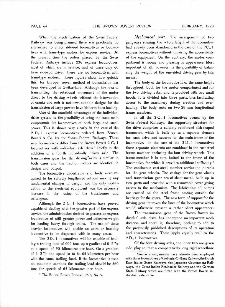
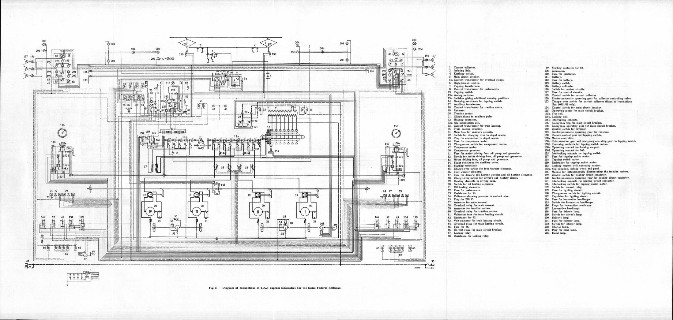
Current collector. 89. Isolating link. 108. Earthing switch. 110. Main circuit breaker. 111. Current transformer for overload relays. 112. High-tension lead-in. 113. Tapping transformer. 116. Current transformer for instruments. 126. Tapping switch. 127. Arcing switches. 129. Switches giving additional running positions. 130. Damping resistance for tapping switch. 132. Auxiliary transformer. Current transformer for traction motor. 134. Reverser. 135. Traction motor. 135a. Ohmic shunt to auxiliary poles. 135b. Heating contactor. 135c. Are suppression coil. 136. Current transformer for train heating. 138. Train heating coupling. 140. Main fuse for auxiliary circuits. 143. Switch for changing over to depot mains. 150. Plug for connection to depot mains. 150a. Fuse for compressor motor. 150c. Change-over switch for compressor motor. 150d. Compressor motor. 150e. Compressor governor. 150 f. Fuse for motor driving fans, oil pump and generator. 155. Switch for motor driving fans, oil pump and generator. 157. Motor driving fans, oil pump and generator. 158. Shunt resistance for auxiliary poles. 159. Starting resistance. 162. Change-over switch for foot warmer elements. 162a. Foot warmer elements. 165. Fuse for driver's cab heating circuits and oil heating elements. 169. Change-over switch for driver's cab heating circuit. 170. Heating elements in driving cabs. 171. Switch for oil heating elements. 176. Oil heating elements. 182. Fuse for instruments. 189. Resistance for 74. 190. Voltmeter showing pressure in contact wire. 192. Plug for 220 V. 194. Ammeter for main current. 195. Overload relay for main current. 196. Ammeter for traction motors. 197. Overload relay for traction motors. 198. Voltmeter fuse for train heating circuit. 199. Resistance for 83. 200. Volt-ammeter for train heating circuit. 201. Overload relay for train heating circuit. 202. Fuse for 86. 203. No-volt relay for main circuit breaker. 204. Locking relay. 205. Resistance for locking relay.
Starting contactor for 53. Generator. Fuse for generator. Battery. Fuse for battery. Battery switch. Battery voltmeter. Switch for control circuits. Fuse for control circuits. Control switch for current collector. Electro-pneumatic operating gear for collector Controlling valve. Change-over switch for current collector (fitted to locomotives Nos. 10901/02 only). Control switch for main circuit breaker. Operating motor for main circuit breaker. Trip coil. Locking disc. Interrupting contacts. Emergency trip for main circuit breaker. Emergency operating gear for main circuit breaker. Control switch for reverser. Electro-pneumatic operating gear for reverser. Remote control gear for tapping switch. Master Controller. Return-motion gear and emergency operating gear for tapping switch. Reversing contacts for tapping switch motor. Operating contact for locking magnet. Operating contact for 165. Interlocking contacts on tapping switch. Fuse for tapping switch motor. Tapping switch motor. Resistance for tapping switch motor. Locking magnet with operating contact. Slip coupling, locking wheel and pawl. Magnet for instantaneously disconnecting the traction motors. Control switch for heating circuit contactor. Electro-pneumatic operating gear for heating circuit contactor. Interlocking contacts for heating circuit contactor. Interlocking switch for tapping switch motor. Switch for no-volt relay. Fuse for lighting circuit. Change-over switch for lighting circuit. Regulator for lighting circuit. Fuse for locomotive headlamps. Switch for locomotive headlamps. Plugs for locomotive headlamps. Locomotive headlamps. Fuse for driver's lamp. Switch for driver's lamp. Driver's lamp. Fuse for interior lamp. Switch for interior lamp. Interior lamp. Plug for hand lamp. Hand lamp.
1. 2. 4. 5. 5a. 6. 7. 8.
13. 13a. 13c. 14. 17. 18. 19. 20. 21. 32. 32a. 33. 35. 41. 42. 43. 44. 45. 47. 50. 51. 52. 53. 54. 55. 65. 66. 67. 68. 69. 70. 71. 72. 73. 74. 75. 77. 78. 79. 80. 8 1 . 82. 83. 84. 85. 86. 87. 88.
Fig . 3. — Diagram of connections of 2 D q 1 express locomotive for the Swiss Federal Railways.

FEBRUARY, 1928 THE BROWN BOVERI REVIEW PAGE 65
is obtained. In this locomotive also, the presence of the transformer disturbs the longitudinal symmetry and it is found necessary to place a Standard bogie at the transformer end of the locomotive, whereas at the other end a Bissel truck is found sufficient.
With the first 2 D 0 1 locomotive No. 10901 brought into Service, the principle of combining the pony axle with the adjacent driving axle to form a truck having its centre pin lying behind the driving axle, as adopted for the locomotives for the Dutch East Indies State Railways1, was also employed. This arrangement has been patented by Brown, Boveri & Co., and its distinguishing feature is that the driving motor, which is rigidly attached to the main frame of the locomotive, transmits the power to a driving axle of the truck through a universal coupling, viz., the in-dividual axle drive. There is a difference, however, between the present design and that adopted for the Java locomotives in the arrangement of the truck, as the pony axle for the 2 D 0 1 locomotive is of the Adams type, which allows the wheels greater freedom with respect to the truck so that they can adapt themselves better to the track at curves. All further 2 D 0 1 locomotives can, if necessary, be fitted with these combined bogies instead of Bissel trucks.
The new locomotives are principally intended for service on the level sections of the line only; they are therefore fitted with the Standard air brake em-ployed by the Federal Railways and are not equipped for electric braking. To increase the braking effect, brakes are also fitted to the wheels of the bogie trucks. The mechanical part of the locomotive was constructed and assembled by the Swiss Locomotive and Machine Works, Winterthur.
Electrical part. The specifications prepared by the Swiss Federal Railway administration have hitherto always contained exact details of the operating con-ditions for which the locomotives were ordered. From these particulars, based on the service requirements and usually prepared from the results of dynamometer-car tests on the various sections, the firms supplying the locomotives were enabled to calculate the Output re-quired. The designers were thus permitted a very considerable degree of freedom in the choice and number of the motors and in the whole arrangement of the mechanical and electrical equipment. As a result
1 The Brown Boveri Review 1926, No. 8, page 190.
BROWN BOVERI 2 1 9 1 7 1
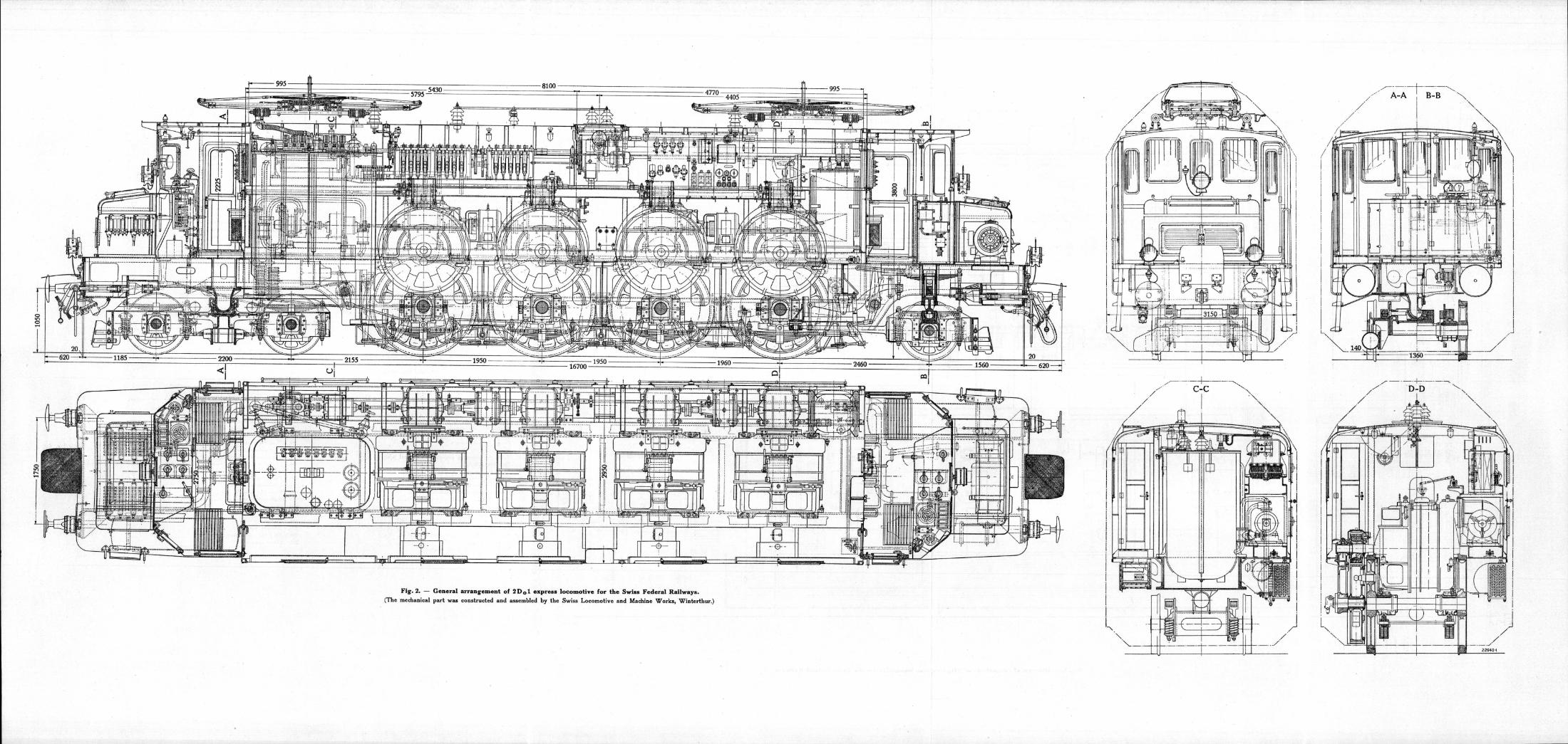
Fig. 4. — Traction motor ready for mounting, one-hour rating 775 H. P.
of this, locomotives of radically different types were sup-plied to the Federal Railways for the same classes of service. The freedom thus given to the firms supplying the material gave the railway administration the op-portunity of instituting comparisons between the various types of locomotives, and enabled them to base their plans for the purchase of further locomotives and the standardization of types on actual results of Operation.
For the first time, however, the specification for the 2 D 0 1 locomotives contains particulars as to the number and Output of the motors, without reference to any particular section of line. The standardization
0WOWM BOVERI 21916-1
Fig. 5. — Traction motor with inspection Cover Over commutator removed.
PAGE 6 THE BROWN BOVERI REVIEW FEBRUARY, 1928
BfiOWN BOVEH1 19305-1
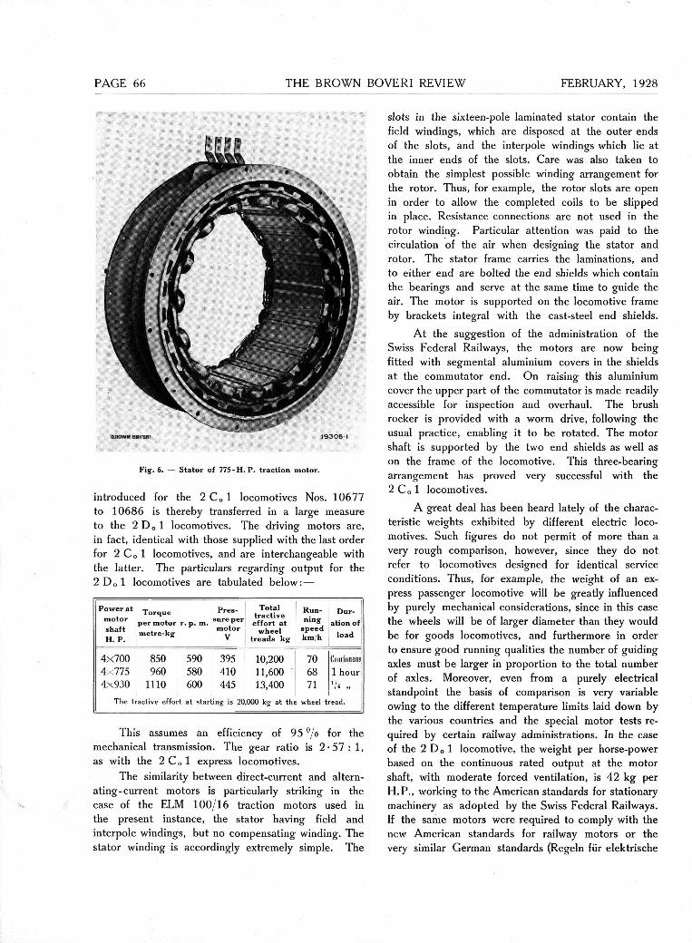
Fig. 6. — Stator of 7 7 5 - H . P . traction motor.
introduced for the 2 C 0 1 locomotives Nos. 10677 to 10686 is thereby transferred in a large measure to the 2 D o 1 locomotives. The driving motors are, in fact, identical with those supplied with the last order for 2 Co 1 locomotives, and are interchangeable with the latter. The particulars regarding Output for the 2 D 0 1 locomotives are tabulated below:—
Power at motor shaft H. P.
Torque per motor metre-kg
r. p. m.
Pres-sure per
motor V
Total tr active effort at
wheel treads kg
Run-ning
speed km/h
Dur-ation of
load
4x700 4x775 4x930
The t
850 960
1110 active effor
590 580 600
t at star
395 410 445
ting is 20
10,200 11,600 13,400
000 kg- at the
70 68 71
wheel t
Continuous 1 hour 7« -
read.
This assumes an efficiency of 95 °/o for the mechanical transmission. The gear ratio is 2 - 5 7 : 1 , as with the 2 Co 1 express locomotives.
The similarity between direct-current and altern-ating-current motors is particularly striking in the case of the ELM 100/16 traction motors used in the present instance, the stator having field and interpole windings, but no compensating winding. The stator winding is accordingly extremely simple. The
slots in the sixteen-pole laminated stator contain the field windings, which are disposed at the outer ends of the slots, and the interpole windings which lie at the inner ends of the slots. Care was also taken to obtain the simplest possible winding arrangement for the rotor. Thus, for example, the rotor slots are open in order to allow the completed coils to be slipped in place. Resistance connections are not used in the rotor winding. Particular attention was paid to the circulation of the air when designing the stator and rotor. The stator frame carries the laminations, and to either end are bolted the end shields which contain the bearings and serve at the same time to guide the air. The motor is supported on the locomotive frame by brackets integral with the cast-steel end shields.
At the suggestion of the administration of the Swiss Federal Railways, the motors are now being fitted with segmental aluminium Covers in the shields at the commutator end. On raising this aluminium cover the upper part of the commutator is made readily accessible for inspection and overhaul. The brush rocker is provided with a worm drive, following the usual practice, enabling it to be rotated. The motor shaft is supported by the two end shields as well as on the frame of the locomotive. This three-bearing arrangement has proved very successful with the 2 Co 1 locomotives.
A great deal has been heard lately of the charac-teristic weights exhibited by different electric loco-motives. Such figures do not permit of more than a very rough comparison, however, since they do not refer to locomotives designed for identical Service conditions. Thus, for example, the weight of an ex-press passenger locomotive will be greatly influenced by purely mechanical considerations, since in this case the wheels will be of larger diameter than they would be for goods locomotives, and furthermore in order to ensure good running qualities the number of guiding axles must be larger in proportion to the total number of axles. Moreover, even from a purely electrical standpoint the basis of comparison is very variable owing to the different temperature limits laid down by the various countries and the special motor tests re-quired by certain railway administrations. In the case of the 2 D 0 1 locomotive, the weight per horse-power based on the continuous rated Output at the motor shaft, with moderate forced Ventilation, is 4 2 kg per H.P., working to the American Standards for s tationary machinery as adopted by the Swiss Federal Railways. If the same motors were required to comply with the new American Standards for railway motors or the very similar German Standards (Regeln für elektrische

FEBRUARY, 1928 THE BROWN BOVERI REVIEW PAGE 6
Bahnen) instead of the aforesaid American Standards for stationary plants, the weight per horse-power of continuous rated Output would be reduced to 37 kg per H. P. It should be added, moreover, that motors of the type in question and for the same power have been built by Brown, Boveri & Co. for another in-stallation, and these motors were lighter by a ton than those mentioned above, from which it will be seen that the figure of 42 kg per H. P. first given can be reduced to 36 for exactly the same Output. These lighter motors could not be employed for the 2 D 0 1 locomotives, however, since the Federal Rail-way administration desired to secure the greatest possible interchangeability and therefore stipulated that the motors used for the 2 D„ 1 locomotives Nos. 10901 —16 should be identical with those used on the 2 C 0 1 locomotives Nos. 10637 to 10686. It will be evident from the few figures given above that these characteristic weights can vary very widely, even without taking account of the mechanical part of the locomotive, when different Standards for the temper-ature limitations of the electrical equipment are used as the basis of the calculations.
The power transformer is of the core type with Sandwich coils and vertical core limbs (Fig. 7). The chief difficulties met with in the design of locomotive
Fig. 7. — Oil-immersed transformer, continuous rating 2500 kVA, 15,000/85-525 V with seven tappings for tapping-switch control.
transformers are caused by the comparatively large number of tappings. Bearing this fact in mind, there-fore, a control system was designed for the 2 D 0 1 locomotives requiring a minimum number of connec-tions to the transformer. The connecting leads for the seven tappings required for speed control may be arranged on the transformer in a manner allowing of easy inspection and overhaul. Two additional taps for 800 and 1000 V respectively are taken from the primary side of the auto-transformer for supplying the train-heating circuits.
Formerly it has been the usual practice to make the overall dimensions of the transformer as small as possible, having regard to the general arrangement of the locomotive. On the new locomotives, however, more space has been found for the transformer and it has thus been possible to increase the height. This has been done by sinking the transformer some 35 cm into the main frame of the 2 D 0 1 locomotive. The better conditions thus obtained permit of improve-ments in design in the interior of the transformer. The design can be made considerably simpler from the point of view of manufacture, and overhauling is facilitated. The extremely heavy mechanical strains to which locomotive transformers are continually subjected caused Brown, Boveri & Co. to tender, and later supply, plain-walled transformer tanks without cooling ribs, such as are general practice for land installations. The first of the single-phase locomotives supplied by Brown, Boveri & Co., for the Swiss Federal Railways were fitted with such transformers. Electric welding is used to secure the external supporting brackets, internal supports, cover flange, and eye bolts for lifting. Since the active part of the transformer and its tank as well as the transformer as a whole must be interchangeable, the tank is built and finished with great accuracy.
The oil is cooled by passing through a cooler of drawn steel tubes located beneath the running board on the side of the locomotive opposite to the individual drive. The cooling system is therefore similar to that used on the 1 B-B 1 Gothard loco-motives 1 which has proved successful in every res-pect. Leaving out of account the saving of a special fan, the cooling system has the advantage of being located outside the locomotive, and consequently re-duces the amount of equipment in the motor com-partment.
Owing to the greater power developed by the motors and the higher running speed, the number of running positions has been increased from 18, which was considered suitable for the previous 2 C 0 1 loco-
1 Revue BBC, 1921, No. 9, page 207.
PAGE 68 THE BROWN BOVERI REVIEW FEBRUARY, 1928
E 157
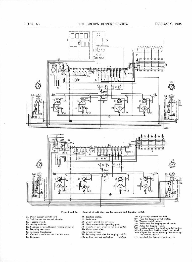
Figs. 8 and 8 a. — Control circuit diagram for motors and tapping switch.
D. Direct-current switchboard. E. Switchboard for control circuits.
13. Tapping switch. 13a Arcing switches. 13c Switches giving additional running positions. 14. Damping resistance. 17. Auxiliary transformer. 18. Current transformer for traction motor. 19. Reverser.
20. Traction motor. 21. Resistance.
140. Control switch for reverser. 143. Electro-pneumatic operating gear. 150. Remote control gear for tapping switch. 150a Master Controller. 150c Return motion. 150d Reversing Controller for tapping switch 150e Locking magnet Controller. [motor.
150f Operating contact for 165b. 157. Fuse for tapping-switch motor. 158. Tapping-switch motor. 159. Resistance for tapping-switch motor. 160. Relay for tapping switch. 162. Locking magnet for tapping-switch motor. 162a Slip coupling, locking wheel, and pawl. 165b Magnet for instantaneously disconnecting
the traction motors. 176. Interlock for tapping-switch motor.
FEBRUARY, 1928 THE BROWN BOVERI REVIEW PAGE 6
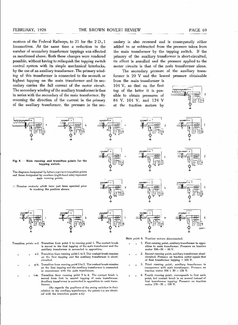
motives of the Federal Railways, to 21 for the 2 D„1 locomotives. At the same time a reduction in the number of secondary transformer tappings was effected as mentioned above. Both these changes were rendered possible, without having to relinquish the tapping switch control system with its simple mechanical interlocks, by the use of an auxiliary transformer. The primary wind-ing of this transformer is connected to the seventh or highest tapping on the main transformer and its sec-ondary carries the füll current of the motor circuit. The secondary winding of the auxiliary transformer is thus in series with the secondary of the main transformer. By reversing the direction of the current in the primary of the auxiliary transformer, the pressure in the sec-
ondary is also reversed and is consequently either added to or subtracted from the pressure taken from the main transformer by the tapping switch. If the primary of the auxiliary transformer is short-circuited, its effect is annulled and the pressure applied to the motor circuits is that of the main transformer alone.
The secondary pressure of the auxiliary trans-former is 20 V and the lowest pressure obtainable from the main transformer is 104 V, so that on the first tap of the latter it is pos-sible to obtain pressures of 84 V, 104 V, and 124 V at the traction motors by
•AWvvi
Fig. 9. — Main running and transition points for the tapping switch.
The diagrams designated by letters represent transition points and those designated by numbers (right-hand side) represent
main running points.
X Denotes contacts which have just been operated prior to reaching the position shown.
m * S
3 ß =
Transition points a-d. Transition from point 0 to running point 1. The contact brush is moved to the first tapping of the main transformer and the auxiliary transformer is connected in Opposition.
„ „ e-f. Transition from running point 1 to 2. The contact brush remains on the first tapping and the auxiliary transformer is short-circuited.
„ „ g-h. Transition from running point 2 to 3. The contact brush remains on the first tapping and the auxiliary transformer is connected in concurrence with the main transformer.
„ „ i-m. Transition from running point 3 to 4. The contact brush is moved from first to second tapping of main transformer. Auxiliary transformer is connected in Opposition to main trans-former.
(As regards the positions of the arcing switches in their relation to the auxiliary transformer, the points i-m are identi-cal with the transition points a-d.)
Main point 0. Traction motors disconnected.
„ „ 1. First running point, auxiliary transformer in Oppo-sition to main transformer. Pressure on traction motor 104—20 = 84 V.
„ „ 2. Second running point, auxiliary transformer short-circuited. Pressure on traction motor equals that of first transformer tapping = 104 V.
„ „ 3. Third running point, auxiliary transformer in concurrence with main transformer. Pressure on traction motor 104 + 20 = 124 V.
„ „ 4. Fourth running point, corresponds to first main point, but contact brush is on second instead of first transformer tapping. Pressure on traction motor 1 7 8 - 2 0 = 158 V.

PAGE THE BROWN BOVERI REVIEW FEBRUARY, 1928
connecting the secondary of the auxiliary transformer successively in Opposition, short-circuited, and in con-currence. Thus three pressures may be obtained at each of the seven positions of the tapping switch, giving in all twenty-one pressure steps for the control of the motors.
The tapping switch comprises three groups of ele-ments (Fig. 8) corresponding to the sequence of Operations described above. The first group consists of the sliding tapping switch 13 with seven steps. The movement of the contact brushes is effected by means of an adjustable chain in place of the threaded spindle formerly employed. The introduction of this new design enabled the insulation of the contact brushes to be modified, resulting in a reduction in the ver-tical dimensions of the tapping switch. The contact bar, contact blocks, and sliding contact brushes are duplicated and the two contact bars are joined in parallel. The contact blocks can be dismounted sep-arately and replaced. The contact bars are also subdivided for the same purpose. By arranging the sliding brushes obliquely and providing a feit lubric-ating device, the formation of corrugations on the bar and blocks is prevented and wear is reduced to within reasonable limits.
The second group of switch elements (13 a) comprises four pairs of arcing switches, each pair co-operating with one of the four traction motors which are connected in parallel. As with the usual type of tapping switch, the main and auxiliary brushes of each pair of arcing switches, in conjunction with a damping resistance, effect the transition from one step of the tapping switch to the next without interrupting the flow of current to the motors. The arcing shields are hinged so that the contacts are readily accessible.
The third group (13 c) of apparatus comprises switches for changing Over and short-circuiting the connections of the auxiliary transformer. Out of re-gard for uniformity, the switches for Controlling the auxiliary transformer are practically identical with the arcing switches described above, although the duty of the former is considerably less severe. However, the brushes for changing over without current, as used with the main arcing switches, are here omitted. Since the switch group 13 c is required to perform three Operations while the tapping switch performs one, a single-toothed gear is placed between the switch groups 1 3 a and 13 c. This not only ensures the correct sequence of Operations but prevents the sliding brushes from being moved unless the change-over switch 13 c is in the correct position for transition, i. e., with the auxiliary transformer connected in Oppo-sition to the main transformer.
The tapping switch is operated from the end occupied by the switch group 13 c, and operation is effected by a 36-V direct-current series motor. Following previous practice for drives of this class, the motor with its slip-coupling, transmission gears, locking magnet and switch, forms a self-contained unit. A novel feature of the arrangement is the trans-ference of the control switching device in a greatly simplified form to the master Controller. This switch was formerly combined with the above operating unit, and performs the function of interrupting the current to the tapping-switch operating motor as soon as the tapping switch has reached the position cor-responding to the setting of the master Controller.
The control of the motors is effected in the following manner. On turning the handwheel 150 a of the master Controller to position 3, for example, the control circuit is completed to the control switch for the reverser 140, and from thence through the contact 150e which is mounted loose on the hollow shaft of the master Controller, to the coil of the locking magnet 162, and thence to the earth line. Current also flows from the control switch 140 through a contact 150d mounted on the hollow shaft of the master Controller in the closed position E, and to the field winding for forward motion of the tapping-switch motor, thence through the in-terlocking contact on the catch, and finally to the earth line. The result is that the locking magnet at t rac ts the catch, and the contact associated with the latter is c losed. Since the motor field is already energized, the motor starts up in the forward direction and operates the tapping switch.
The hollow shaft of the master Controller is mechanically connected with the tapping switch through differential gearing in such a way that the motion transmitted to the aforesaid hollow shaft by the tapping switch takes place in the opposite direction to that of the handwheel of the master Controller.
Since when turning the handwheel of the master Controller to the third position, as assumed in this example, there will only be a momentary pause on position 1 and 2, the roller lever on the idle shaft of the master Controller is not engaged. The contact in the locking magnet circuit 150 e actuated by the roller lever will therefore remain closed. The roller lever is only engaged when the handwheel is allowed to remain in position 3, and the contact Controlling the locking magnet is then broken so that the latter is de-energized. The tapping-switch operating motor remains connected, however, until the pawl of the locking wheel is engaged, which occurs when the notch has been turned to the highest position. As
FEBRUARY, 1928 THE BROWN BOVERI REVIEW PAGE
soon as the pawl is brought into engagement, the contact associated therewith interrupts the circuit of the control motor. The armature which continues to rotate, although disconnected, is braked by the slip coupling, the tapping switch being held in position by the locking disc.
If the control handwheel is turned further to a higher running position, to point 10 for example, the roller lever operated from the tapping switch is rotated in the opposite direction to the control hand-wheel and is engaged just before the tapping switch reaches position 10, thereby once more interrupting the contact Controlling the locking magnet and bring-ing the motor to rest.
The sequence of Operations is similar when the handwheel of the master Controller is turned from a higher, back to a lower position, e. g. , from the third to the second point. Turning the handwheel from position 3 to position 2 causes the contact Controlling the locking magnet to be closed, but at the same time the friction-operated commutator contacts 150 d Controlling the tapping-switch motor are brought into position A. The field winding for the reverse rotation of the motor is thus connected to the supply and the tapping switch commences its return motion. As soon as the tapping switch reaches position 2, the supply to the motor is interrupted exactly as described above, by means of a contact actuated by the tapping switch, and the latter is then locked in position 2.
The adoption of the servo-motor control system described above enables the number of control con-nections to be reduced to a minimum, and the number of contacts is also substantially diminished. By making the mechanical connection between the tapping switch and the hollow shaft of the master Controller somewhat stronger than is absolutely necessary (under normal working conditions this connection is very lightly stressed) for transmitting the motions of the tapping switch to the hollow shaft, it becomes feasible to operate the tapping switch by hand from either driving cab in case of emergency, through the said connection, it being merely necessary to attach a suitable handwheel. (This is shown dotted in the general diagram.)
In addition, the position indicator on the top plate of the Controller can be very easily combined with the mechanical repeat gear of the tapping switch. The driver is thus enabled to keep a check on the operation and position of the tapping switch at all times.
In the various positions of the tapping switch, the locking magnet not only interrupts the current
tapping switch. Above: Spark-extinguishing switch for motor closed. Below: „ „ „ „ „ open.
of the control motor but also blocks the tapping switch. If, then, the catch of the locking magnet is released, this can be directly accomplished by switch-ing over the control motor to rheostatic braking. The diagram shown in Fig. 8 a applies to this case. The switching-over to the braking position is per-formed by the change-over switch operated by the locking pawl. One field of the control motor is externally excited, from the battery, the braking effect being thus increased. This braking effect lasts until the control motor has practically come to rest, as it is only then that the relay 1 6 0 for the latter operates.
In cases of urgency, as in the event of sud-denly receiving a signal to stop, for example, it is desirable to be able to interrupt the motor current instantaneously. The high-tension circuit breaker is not to be recommended for this duty, since it controls the supply to all the auxiliary services on the train and, moreover, too frequent operation would lead to deterioration of the oil. On this account the 2 D 0 1 locomotives are fitted with a quick-acting cut-out arrangement which enables the traction motors to be instantaneously disconnected from the tapping switch.
For the quick-acting cut-out, the upper arms of the fork levers associated with the cams of the motor
PAGE THE BROWN BOVERI REVIEW FEBRUARY, 1928
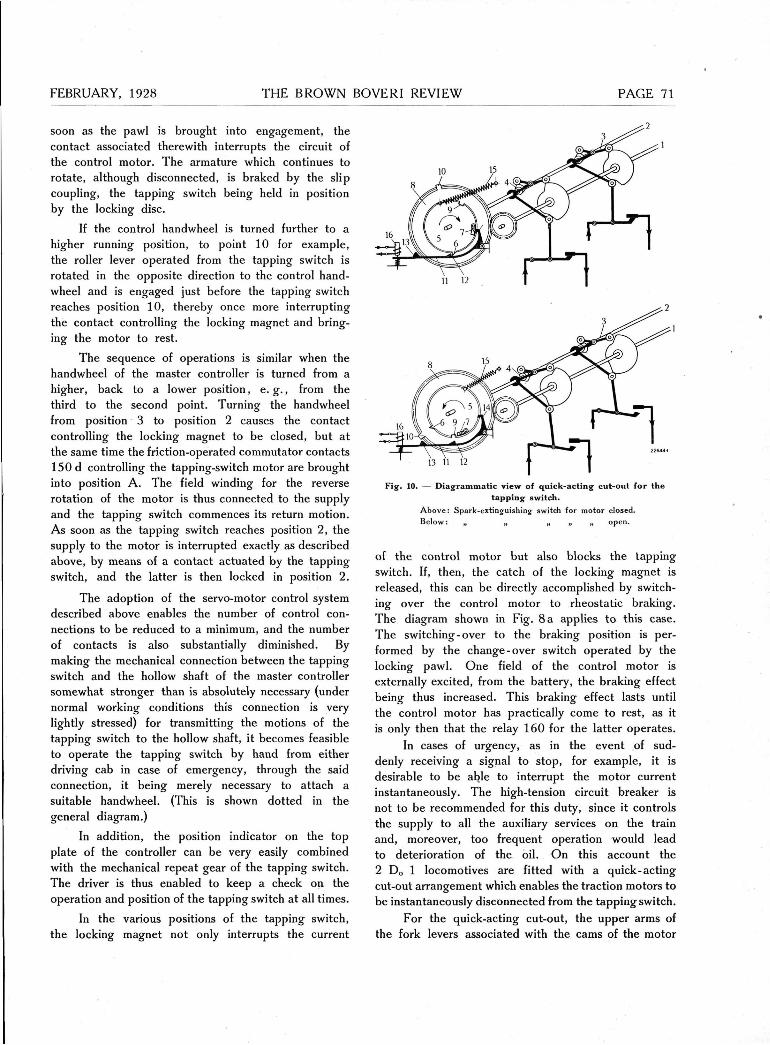
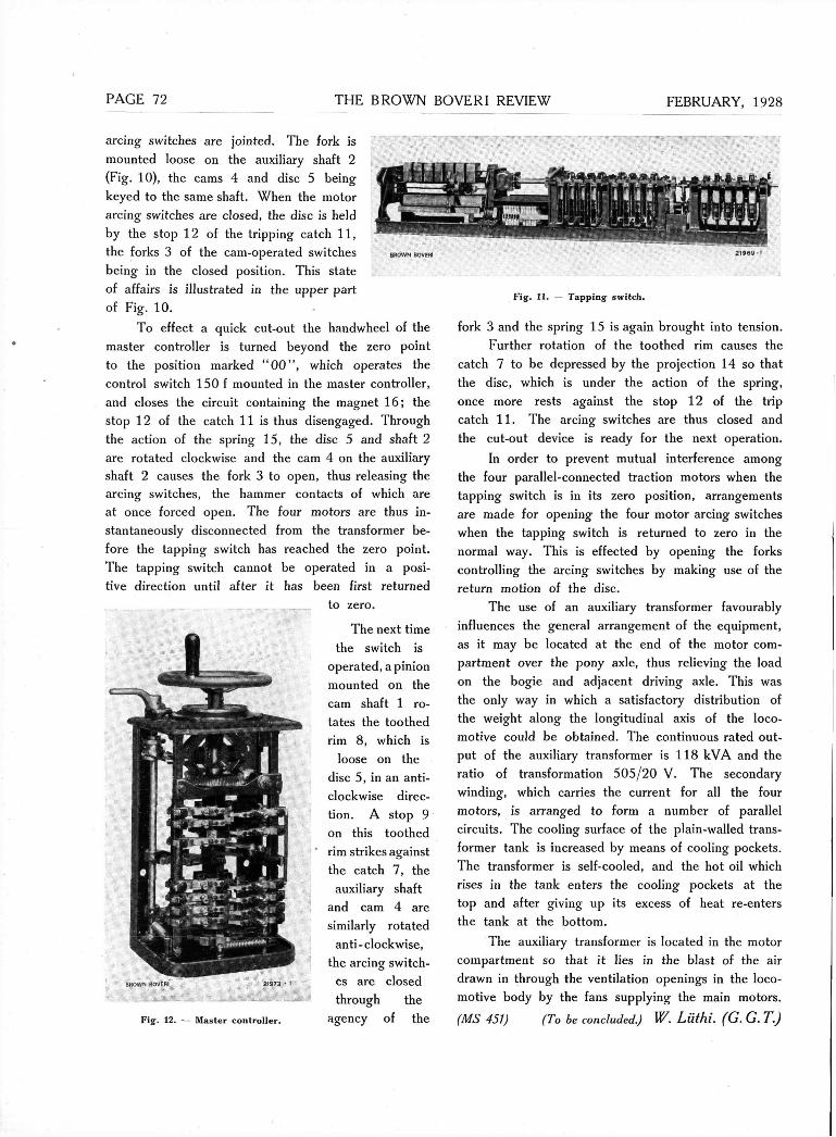
arcing switches are jointed. The fork is mounted loose on the auxiliary shaft 2 (Fig. 10), the cams 4 and disc 5 being keyed to the same shaft. When the motor arcing switches are closed, the disc is held by the stop 12 of the tripping catch 11, the forks 3 of the cam-operated switches BROWN BOVEffl
being in the closed position. This State
of affairs is illustrated in the upper part of Fig. 10.
To effect a quick cut-out the handwheel of the master Controller is turned beyond the zero point to the position marked " 0 0 " , which operates the control switch 150 f mounted in the master Controller, and closes the circuit containing the magnet 16; the stop 12 of the catch 11 is thus disengaged. Through the action of the spring 15, the disc 5 and shaft 2 are rotated clockwise and the cam 4 on the auxiliary shaft 2 causes the fork 3 to open, thus releasing the arcing switches, the hammer contacts of which are at once forced open. The four motors are thus in-stantaneously disconnected from the transformer be-fore the tapping switch has reached the zero point. The tapping switch cannot be operated in a posi-tive direction until after it has been first returned
to zero.
The next time the switch is
operated, a pinion mounted on the cam shaft 1 ro-tates the toothed rim 8, which is
loose on the disc 5, in an anti-clockwise direc-tion. A stop 9 on this toothed rim strikes against the catch 7, the
auxiliary shaft and cam 4 are similarly rotated
anti-clockwise, the arcing switch-
es are closed through the
agency of the
Fig. 11. Tapping switch.
fork 3 and the spring 15 is again brought into tension. Further rotation of the toothed rim causes the
catch 7 to be depressed by the projection 14 so that the disc, which is under the action of the spring, once more rests against the stop 12 of the trip catch 11. The arcing switches are thus closed and the cut-out device is ready for the next Operation.
In order to prevent mutual interference among the four parallel-connected traction motors when the tapping switch is in its zero position, arrangements are made for opening the four motor arcing switches when the tapping switch is returned to zero in the normal way. This is effected by opening the forks Controlling the arcing switches by making use of the return motion of the disc.
The use of an auxiliary transformer favourably influences the general arrangement of the equipment, as it may be located at the end of the motor com-partment over the pony axle, thus relieving the load on the bogie and adjacent driving axle. This was the only way in which a satisfactory distribution of the weight along the longitudinal axis of the loco-motive could be obtained. The continuous rated Out-put of the auxiliary transformer is 118 kVA and the ratio of transformation 505/20 V. The secondary winding, which carries the current for all the four motors, is arranged to form a number of parallel circuits. The cooling surface of the plain-walled trans-former tank is increased by means of cooling pockets. The transformer is self-cooled, and the hot oil which rises in the tank enters the cooling pockets at the top and after giving up its excess of heat re-enters the tank at the bottom.
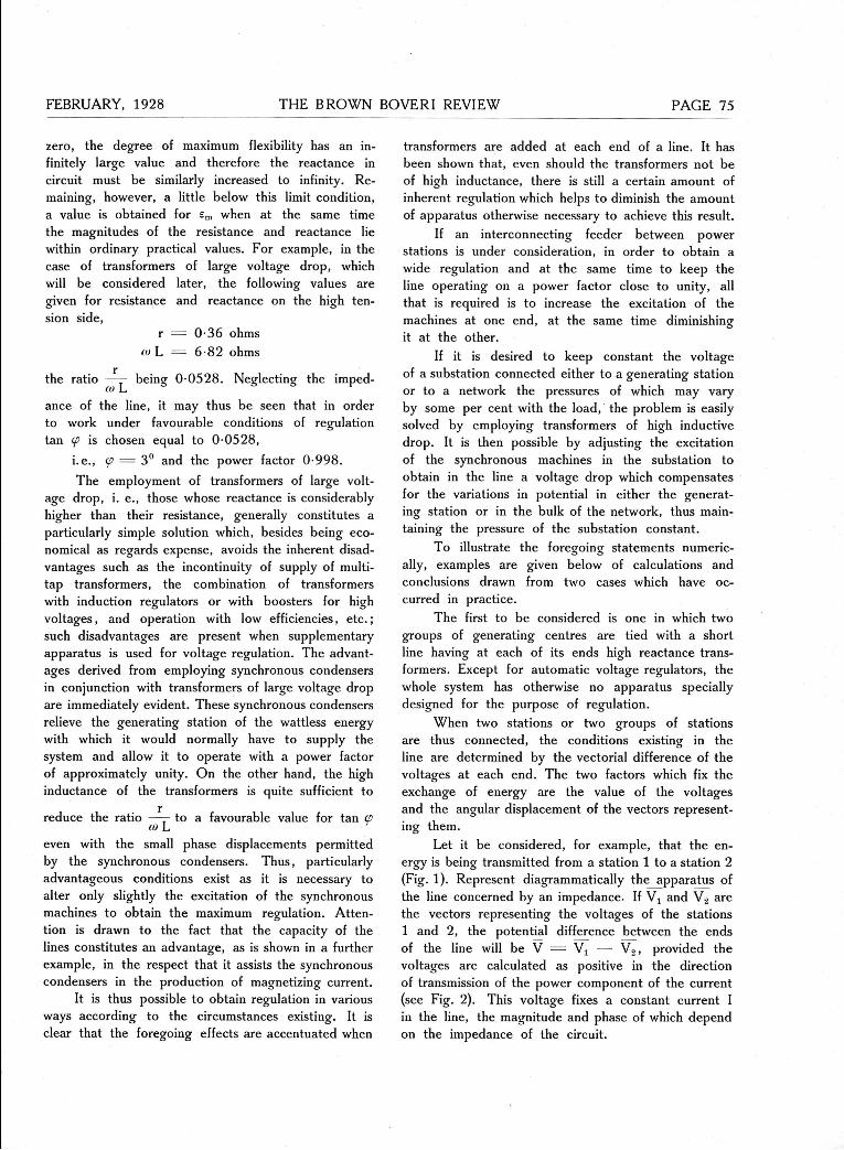
The auxiliary transformer is located in the motor compartment so that it lies in the blast of the air drawn in through the Ventilation openings in the loco-motive body by the fans supplying the main motors. (MS 451) (To be concluded.) W. Lüthi. (G. G. T.) Fig-. 1 2 . — M a s t e r C o n t r o l l e r .

FEBRUARY, 1928 THE BROWN BOVERI REVIEW PAGE
THE PARALLEL OPERATION
INDEPENDENT VOLTAGE REGULATION BY MEANS OF THE POWER FACTOR.
IT has become more and more evident that due to the ever increasing needs of industry and the neces-
sity for economy in every power Station, schemes for interconnection have been devised which are often very complicated, and which have introduced a variety of problems.
As well as meeting the demands of other inter-connected power plants, which is of course the ob-ject of parallel operation, power stations are called upon to supply energy independently under the pos-sibly severe conditions imposed on them by their own network. It is particularly necessary that the voltage be maintained within certain limits at each point of generation of energy in spite of the variations result-ing from the exchange of power. In some cases it is necessary that it should be kept absolutely constant.
The problem of voltage regulation here under consideration has been successfully solved in many different ways. These may be divided into two classes, the first consisting of the introduction into the circuit of an additional electromotive force, which compen-sates either for the drop in pressure alone, or also for the poor power factor resulting from the distri-bution of energy in the transmission lines and in the apparatus comprising the load. Such a result is ob-tained by means of the compounding of voltage reg-ulators or by multi-tap transformers, boosting trans-formers, induction regulators or by rotary boosters.
The other methods may be grouped under the second class of those which, by influencing the reac-tive component of the current, obtain from the re-sultant current a pressure drop which constitutes the elements of regulation. In this way, no active com-ponent of the current but merely magnetizing current is introduced into the circuit. Thus a machine re-quires no more watt-current than is sufficient to cover its losses. Of these solutions the placing of synchron-ous condensers in chosen parts of the network is most common.
It is nevertheless possible to reduce the amount of such apparatus installed and even, in most cases, entirely to dispense with it, if the power factor of the exchange currents between stations is slightly
OF GENERATING STATIONS. Decimal index 621. 312. 0064.
varied above or below unity. Thus voltage regulation and its maintenance at a desired value at both ends of an interconnecting feeder are possible by Controlling the wattless current transferred. It is similarly possible to regulate the voltage drop in a line joining a main Station and a substation containing a synchronous condenser, keeping a constant voltage in the latter. These alterations in power factor are brought about by the Variation of the excitation of the synchronous machines. Since unity is the maximum value attained by the continuous function cos <p, it may be noticed that it is possible to vary the amount of phase dis-placement within comparatively large limits and yet
Fig. 1. — Vector diagram of the voltages and voltage drop in an overhead power transmission line. VC = Ir = ohmic drop in the line.
C V c - luL — inductance drop in the line.
obtain a certain flexibility in the regulation of the voltage without the power factor varying greatly from unity. This flexibility, however, may be considerably increased by artificially augmenting the reactance of the interconnecting lines of a system, either by inserting choke coils, which may also be used for other purposes, or more simply by increasing the coefficient of self-induction of the transformers. Both arrangements present considerable advantages from other points of view.
It is simple to prove that for a small phase displacement between the exchange or the trans-mitted current and the pressure, the greatest flexibility

PAGE 4 THE BROWN BOVERI REVIEW FEBRUARY, 1928
of regulation is obtained when the reactance of all the interconnecting lines and apparatus of the system is much larger than its resistance.
Consider for example an overhead line. Neglect the capacity as compared with the larger values of resistance r and reactance co L. V c being the volt-age of the Station, I the exchange current, i. e., the current transmitted to the other Station, and <p the angle through which it is displaced from V c , it is a simple matter to find, as shown in Fig. 1, the volt-age V which exists at the far end of the line. Since the angle VOVc is small and the vectors OA and OV sufficiently long in comparison with AV, the numerical value of OV may be assumed, without in-troducing any appreciable error, to equal that of its projection OA on OVc and hence the equation
V c = V -)- I r cos <p -)- wL I sin <p. If the voltage drop in the line, V c — V, is called J V, it may be said that
/! V = I (r cos <p -(- (o L sin <p). Should the phase displacement <p alter by an
infinitely small amount, a similarly small Variation of J V, given by the equation below, will follow
d (.:/ V) = I ("' L cos W — r sin (p) d<p. The condition required in Order that an altera-
tion d <p should equal the maximum Variation d (j V) is that
(«KL COS (p — r sin (f) d <p
which reduces to
0
wL tan W.
This equation shows that for each value of the phase displacement there is a corresponding and most favourable ratio of the resistance to the reactance, this ratio having a value of
r sin <p (o L cos <p
Considering the limiting condition when the dis-placement is zero, it is seen from the equa-tion that the maximum flexibility is obtained when co L, the reactance, has a finite value and the re-sistance r is zero, or by allowing the resistance to have a finite value, in which case the reactance must be infinitely large. It is obvious that the degree of flexibility of regulation will not be the same in both these cases. This point will be referred to later. Since the transmission of energy with as high a power factor as possible will always be attempted, the above limiting condition illustrates the practical use of the
formula, as, if this is so, Operation without phase displacement will be closely approached. To obtain good regulation in the manner indicated, it is there-fore necessary for the transmission line with its ac-companying apparatus to have a reactance appre-ciably larger than its resistance. (In the lay-out of electrical networks a tendency is actually shown towards this augmentation of the reactance already in circuit.) On the other hand, the most favourable ratio of the resistance to the reactance increases rapidly with the angle of displacement com-mencing from 0°; it varies in fact proportionally to tan <p. To obtain, therefore, this favourable ratio
r
co L with values of resistance and coefficient of self-
induction which do not exceed limits allowable in practice, it is only necessary to work on a power factor very slightly removed from unity.
This degree of flexibility of regulation, which will be called e, may also be defined by the differential d U V )
d <p -, that is to say, the ratio of the change of
voltage drop to the change of phase displacement. The following equation may therefore be written:
d(z/V) dcp
In the limiting condition this may be written I io L
I (co L cos cp — r sin (f)
cos cp
I r
(cos 2 cp — sin 2 cp)
(cos 2 cp — sin 2 cp) sin cp
When it is desired to find the most suitable value of the reactance in a circuit whose resistance is known, it will be noticed that the second form of the equation shows more clearly the conditions to be observed. It gives then the maximum values of the degree of flexibility of regulation as a func-tion of phase displacement, assuming the maximum condition to be satisfied.
The following expression may also be written: £m = I r (cos cp cot cp — sin cp).
When the phase displacement is relatively small and the power factor is practically unity, sin cp as compared with cot cp may be neglected and the expression then written:
____ I r £ m ~ tan cp
From this it will be seen that if the limiting condition is reached when the phase displacement is
FEBRUARY, 1928 THE BROWN BOVERI REVIEW PAGE 5
zero, the degree of maximum flexibility has an in-finitely large value and therefore the reactance in circuit must be similarly increased to infinity. Re-maining, however, a little below this limit condition, a value is obtained for em when at the same time the magnitudes of the resistance and reactance lie within ordinary practical values. For example, in the case of transformers of large voltage drop, which will be considered later, the following values are given for resistance and reactance on the high ten-sion side,
r — 0-36 ohms (0 L = 6-82 ohms
r the ratio — being 0-0528. Neglecting the imped-ance of the line, it may thus be seen that in order to work under favourable conditions of regulation tan <p is chosen equal to 0-0528,
i.e., <p — 3° and the power factor 0-998. The employment of transformers of large volt-
age drop, i. e., those whose reactance is considerably higher than their resistance, generally constitutes a particularly simple Solution which, besides being eco-nomical as regards expense, avoids the inherent disad-vantages such as the incontinuity of supply of multi-tap transformers, the combination of transformers with induction regulators or with boosters for high voltages, and operation with low efficiencies, etc.; such disadvantages are present when supplementary apparatus is used for voltage regulation. The advant-ages derived from employing synchronous condensers in conjunction with transformers of large voltage drop are immediately evident. These synchronous condensers relieve the generating Station of the wattless energy with which it would normally have to supply the system and allow it to operate with a power factor of approximately unity. On the other hand, the high inductance of the transformers is quite sufficient to
r reduce the ratio —— to a favourable value for tan W co L even with the small phase displacements permitted by the synchronous condensers. Thus, particularly advantageous conditions exist as it is necessary to alter only slightly the excitation of the synchronous machines to obtain the maximum regulation. Atten-tion is drawn to the fact that the capacity of the lines constitutes an advantage, as is shown in a further example, in the respect that it assists the synchronous condensers in the production of magnetizing current.
It is thus possible to obtain regulation in various ways according to the circumstances existing. It is clear that the foregoing effects are accentuated when
transformers are added at each end of a line. It has been shown that, even should the transformers not be of high inductance, there is still a certain amount of inherent regulation which helps to diminish the amount of apparatus otherwise necessary to achieve this result.
If an interconnecting feeder between power stations is under consideration, in order to obtain a wide regulation and at the same time to keep the line operating on a power factor close to unity, all that is required is to increase the excitation of the machines at one end, at the same time diminishing it at the other.
If it is desired to keep constant the voltage of a substation connected either to a generating Station or to a network the pressures of which may vary by some per cent with the load, the problem is easily solved by employing transformers of high inductive drop. It is then possible by adjusting the excitation of the synchronous machines in the substation to obtain in the line a voltage drop which compensates for the variations in potential in either the generat-ing Station or in the bulk of the network, thus main-taining the pressure of the substation constant.
To illustrate the foregoing statements numeric-ally, examples are given below of calculations and conclusions drawn from two cases which have oc-curred in practice.
The first to be considered is one in which two groups of generating centres are tied with a short line having at each of its ends high reactance trans-formers. Except for automatic voltage regulators, the whole system has otherwise no apparatus specially designed for the purpose of regulation.
When two stations or two groups of stations are thus connected, the conditions existing in the line are determined by the vectorial difference of the voltages at each end. The two factors which fix the exchange of energy are the value of the voltages and the angular displacement of the vectors represent-ing them.
Let it be considered, for example, that the en-ergy is being transmitted from a Station 1 to a Station 2 (Fig. 1). Represent diagrammatically the apparatus of the line concerned by an impedance. If and V s are the vectors representing the voltages of the stations 1 and 2, the potential difference between the ends of the line will be V = V ( — V 2 , provided the voltages are calculated as positive in the direction of transmission of the power component of the current (see Fig. 2). This voltage fixes a constant current I in the line, the magnitude and phase of which depend on the impedance of the circuit.

PAGE 76 FEBRUARY, 1928
The current, on the other hand, is displaced from the voltage V 2 of the receiving Station by an angle c?2. Thus it is seen that under these conditions the Station 2 receives V2 I2 cos <f« kilowatts of energy in phase, and V 2 I2 sin <p2 kVA of wattless energy. Similarly the Station 1 delivers watt energy to the value of Vj Ii cos <p1 kW, the amount of wattless energy being V t sin <pl kVA. (It may be noticed that in the present case the current 1 is that flowing in the windings of the transformers belonging to the corresponding stations.) It is seen also that definite values of the active and reactive currents exchanged in the system correspond to each value both of the pressure Vx and V 2 and of their angular displacement Since the impedance between the two stations may be considered constant, the only means of altering the Service conditions is either to change the algebraic value of the voltages by altering the excitation, or to vary the angle l̂, i.e., by regulation of steam to the turbines. For operation on a fixed load the admission of steam is not varied and the angle remains constant. Under these con-ditions it is obviously always possible to modify the voltage of generating stations by varying throughout the excitation of the alternators and thus changing the power factor. Thus for a fixed exchange of in-phase current, the power factor corrects the variations of voltage in such a manner that, whatever the load, a certain power factor always corresponds to each value of the voltage. On the other hand, considering the matter in the reverse order, for given potentials at each end of the line, it is possible to transmit variable loads maintaining their pressures constant by changing the power factor at the near and the far Station. It will be seen that this results in acting on the wattless component of the transmission current in such a way as to allow a variable exchange of watt current with a constant voltage drop in the line joining the two stations. (This drop in voltage may some-times be reduced to zero.)
For each value of the load it is possible to draw a curve representing the voltage in each Station (or of the voltage drop between them) as a function of the power factor, or inversely, for each value of the voltage in each of the stations (or voltage drop), a curve of the load as a function of the power factor.
The first example just considered may be illus-trated numerically as follows. Two groups of stations, the one having a total installed capacity of 150,000 kW and the other of 50,000 kW, each feed a system with a working pressure of 6000 V, the mean power factor being 0-8. The bus-bars of the two groups are connected through transformers by a 15,000-V
line which is designed to allow the transfer of 10,000 kW in either direction.
From the point of view of the regulation as well as of the power factor of the networks at each end of the line, the best conditions exist when active and reactive energy is transmitted in the same direction. The most unfavourable example has nevertheless been considered—that in which in-phase and quadrative current is exchanged in opposite directions—and re-presents the transmission of power from the Station at the lowest pressure to that at the highest. It will be seen that also under these circumstances, the Oper-ation of the system is very good. The case in which the line transmits no active energy, irrespective of the values of the potentials at its extremities, is discussed later.
The transformers serving each end of the trans-mission line are in every way identical, all possessing the following characteristics:—
Normal Output 5000 kVA. Frequency 50 cycles. Ratio of transformation . . . . 6000/15,000. Impedance voltage 15 % . Magnetizing current 6 %• Coefficient of j high-tension side = 0-0217 H. self-induction ( low-tension side = 0-003275 H.
The voltage drop in the transformers being essen-tially inductive, it is possible, as is shown by the cal-culations and vectorial diagrams, to neglect the power component of the current required to compensate for the iron losses. Account, however, has been taken of it in considering no-load operation.
In order to transmit the required load, two trans-formers are placed in parallel at each end of the line.
In the example considered, due to the shortness of the line, its inductance has been considered negli-gible in comparison with that of the transformers; this can have only the slightest influence on the results. For longer lines, however, it is obviously necessary to take into consideration the wattless com-ponent of the current due to the impedance of the line. In the case of overhead lines, this component of the current, like that due to the transformers them-selves, would be lagging, as then the inductance would outweigh the effect due to the capacity. The reverse is generally true of cables as they have a large in-herent capacity effect, the idle component due to this helping advantageously to diminish the magnetizing current otherwise taken from the generators.
The method used to determine the magnitude of the electrical conditions present in the operation of transformers is the usual vector method, illustrated in
FEBRUARY, 1928 THE BROWN BOVERI REVIEW PAGE
the following, which may easily be applied when the magnetizing current, the resistance, and the coefficient of self-induction are known. These values may also be calculated should the various losses and the total voltage drop across the transformer be known. It is a satisfactory method giving very accurate results and is based on the simple application of Ohm's law in the primary and secondary circuits of the transformers, and on the relation existing between the primary cur-rents, the secondary currents, and the no-load currents.
The following vectorial equations are easily ob-tained when the ohmic drop is neglected.
E" = V " + wL T" V' - E7 tuL I'
I0 = r + " " I" n
E in the above equations represents the E. M. F.,
V the voltage, L the coefficient of self-induction, , the ratio of transformation and co the angular velocity.
Consider for example the Station which is receiv-ing the wattless energy. For a specific pressure oper-ating throughout the Station and for a certain load trans-mitted, it is possible to calculate the primary voltage of the step-down transformer of the Station as soon as a value for the power factor in the secondary is assumed.
Treating the other end of the line in a similar manner, the voltage and the power factor on the primary side of the step-up transformer may be cal-culated. The behaviour of the secondary side is deter-mined by previous knowledge of the primary side of the receiving transformer. For a given Output in kW sent from one Station to another, it is thus possible to calculate the reactive energy acting at each end of the line as well as in the line itself. The power factor at which various portions of the connected system are transferring energy will then be known, that is to say, at the supply Station, in the line connecting it to the receiving one, and in the latter itself. At the sarae time, the difference between the voltages in each Station (in other words the total voltage drop of the line) as well as their angular displacement may be determined.
By repeating these calculations for different values of the power factor on the secondary side of the receiving Station and also for various loads, a number of curves may be drawn based on the Variation of load and showing the way in which the magnitudes of the electrical conditions in the line alter. From this set of curves it is easy to deduct the variations required to be made in the power factor in order that any load with a predetermined voltage drop, or without any
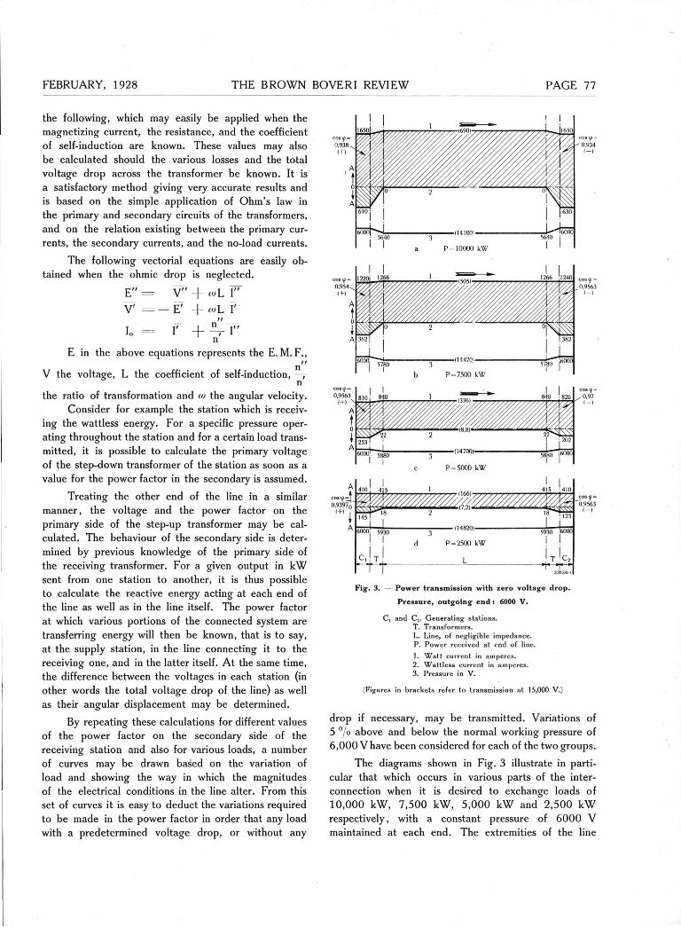
Fig. 3. — Power transmission with zero voltage drop.
Pressure, outgoing end ! 6000 V.
C, and C.. Generating stations. T. Transformers. L. Line, of negligible impedance. P. Power received at end of line. 1. Watt current in amperes. 2. Wattless current in amperes. 3. Pressure in V.
(Figures in brackets refer to transmission at 15,000 V.)
drop if necessary, may be transmitted. Variations of 5 °/o above and below the normal working pressure of 6,000 V have been considered for each of the two groups.
The diagrams shown in Fig. 3 illustrate in parti-cular that which occurs in various parts of the inter-connection when it is desired to exchange loads of 10,000 kW, 7,500 kW, 5,000 kW and 2,500 kW respectively, with a constant pressure of 6000 V maintained at each end. The extremities of the line
*>780
P-7500 kW
P = 2500 kW
L

PAGE THE BROWN BOVERI REVIEW FEBRUARY, 1928
äva„) Fig. 4. — Curves showing the Variation of react ive energy as a function of the voltage drop for
different loads transmitted by an intercommunicat ing line. A. Station receiving watt current. D. Station sending watt current.
are actually the windings of the transformers and it is to these windings that the indicated values of the power factor on the diagram are applicable.
The power factor of both networks, on the other hand, is not greatly influ-enced by the exchanges of reactive energy required by regulation. Thus in the particular case shown in Fig. 3, i. e., when the pres-sure drop along the line is zero, if it is supposed that both the networks, previous to connection, had been sup-plying energy with a power factor of 0 • 8, the values of their power factors given below are those resulting from interconnection.
The curves in Fig. 4 show the variations of reac-tive energy which correspond to the exchange of different loads for given values of the voltage at the extremities of the line. Each curve gives the value of the reactive current as a function of A V,
the algebraic difference between the voltages at each end. These curves are simple to understand if it is remembered that the angular displacement of the vectors representing
1. W a t t energy has been exchanged in the direction of the 50,000-kW group from the 150,000-kW group.
Load in k W 10,000 7,500 5,000 2,500
A v e r a g e p o w e r f a c t o r
o u t g o i n g e n d . . 0 - 7 9 0 - 7 9 0 - 7 9 0 - 7 9
A v e r a g e p o w e r f a c t o r
i n c o m i n g e n d 0 - 8 7 0 - 8 5 2 0 - 8 3 4 0 - 8 2
•mV/. 12 Ä/ 10
8 N 0 / : 6 Y / «OIFC 4
2 A 0 R
0,92 1 /Js/ 0 9 0 8 0 7 cos ip 4
/« / ,0
/ 12 -JV*/. i 231361
Fig. 5. — Primary of t ransformer at outgoing Station. Variation of the power factor as a function of the voltage drop in the line.
2. Wat t energy has been e x c h a n g e d in the direction of the 150,000-kW group from the 50,000-kW group.
Load in k W 10,000 7,500 5,000 2,500
A v e r a g e p o w e r f a c t o r
o u t g o i n g e n d 0 - 7 6 6 0 - 7 6 8 5 0 - 7 8 1 0 - 7 9 2
A v e r a g e p o w e r f a c t o r
i n c o m i n g e n d 0 - 8 2 5 0 - 8 2 0 - 8 1 8 0 - 8 0 5
+ <iV"/„
Fig . 6. — Secondary of t ransformer at incoming Station. Variation of the power factor as a function of the voltage drop in the line.
FEBRUARY, 1928 THE BROWN BOVERI REVIEW PAGE
P=40000 kW
kW
COStf 0,1
kVA
275 | 0
i / j H T 22ÖT x i
P=0 kW
1. Energy in kW. 2. Wattless energy in kVA. 3. Pressure in kV.
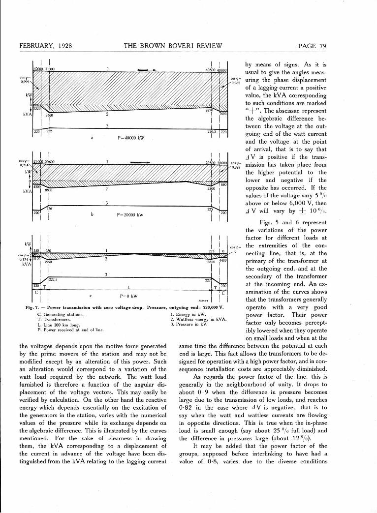
Fig. 7. — Power transmission with zero voltage drop. Pressure, outgoing end : 220,000 V.
C. Generating stations. T. Transformers. L. Line 100 km long. P. Power received at end of line.
the voltages depends upon the motive force generated by the prime movers of the Station and may not be modified except by an alteration of this power. Such an alteration would correspond to a Variation of the watt load required by the network. The watt load furnished is therefore a function of the angular dis-placement of the voltage vectors. This may easily be verified by calculation. On the other hand the reactive energy which depends essentially on the excitation of the generators in the Station, varies with the numerical values of the pressure while its exchange depends on the algebraic difference. This is illustrated by the curves mentioned. For the sake of clearness in drawing them, the kVA corresponding to a displacement of the current in advance of the voltage have been dis-tinguished from the kVA relating to the lagging current
by means of signs. As it is usual to give the angles meas-uring the phase displacement of a lagging current a positive value, the kVA corresponding to such conditions are marked " + " . The abscissae represent the algebraic difference be-tween the voltage at the out-going end of the watt current and the voltage at the point of arrival, that is to say that J V is positive if the trans-mission has taken place from the higher potential to the lower and negative if the opposite has occurred. If the values of the voltage vary 5 °/o above or below 6,000 V, then //V will vary by + 1 0 % .
Figs. 5 and 6 represent the variations of the power factor for different loads at the extremities of the con-necting line, that is, at the primary of the transformer at the outgoing end, and at the secondary of the transformer at the incoming end. An ex-amination of the curves shows that the transformers generally operate with a very good power factor. Their power factor only becomes percept-ibly lowered when they operate on small loads and when at the
same time the difference between the potential at each end is large. This fact allows the transformers to be de-signed for Operation with a high power factor, and in con-sequence installation costs are appreciably diminished.
As regards the power factor of the line, this is generally in the neighbourhood of unity. It drops to about 0 • 9 when the difference in pressure becomes large due to the transmission of low loads, and reaches 0-82 in the case where J V is negative, that is to say when the watt and wattless currents are flowing in opposite directions. This is true when the in-phase load is small enough (say about 25 °/o füll load) and the difference in pressures large (about 1 2 % ) .
It may be added that the power factor of the groups, supposed before interlinking to have had a value of 0-8, varies due to the diverse conditions
I
N -
PAGE THE BROWN BOVERI REVIEW FEBRUARY, 1928
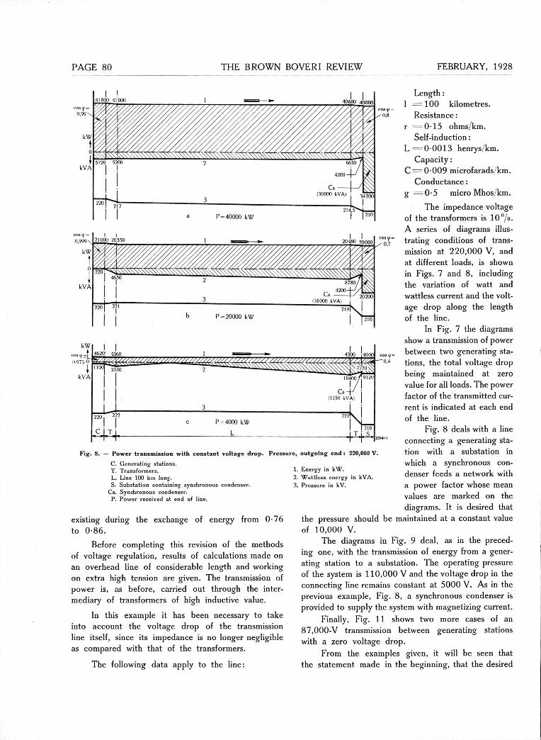
Length : 1 = 100 kilometres.
Resistance: r = 0 - 1 5 ohms/km.
Self-induction: L = 0 0013 henrys/km.
Capacity: C = 0-009 microfarads/km.
Conductance: g = 0 - 5 micro Mhos/km.
The impedance voltage of the transformers is 1 0 % . A series of diagrams illus-trating conditions of trans-mission at 220,000 V, and at different loads, is shown in Figs. 7 and 8, including the Variation of watt and wattless current and the volt-age drop along the length of the line.
In Fig. 7 the diagrams show a transmission of power between two generating sta-tions, the total voltage drop being maintained at zero value for all loads. The power factor of the transmitted cur-rent is indicated at each end
Fig. 8. — Power transmission with constant voltage drop. Pressure, outgoing end : 220,000 V.
C. Generating stations. T. Transformers. L. Line 100 km long. S. Substation containing synchronous condenser.
Cs. Synchronous condenser. P. Power received at end of line.
existing during the exchange of energy from 0-76 to 0-86.
Before completing this revision of the methods of voltage regulation, results of calculations made on an overhead line of considerable length and working on extra high tension are given. The transmission of power is, as before, carried out through the inter-mediary of transformers of high inductive value.
In this example it has been necessary to take into account the voltage drop of the transmission line itself, since its impedance is no longer negligible as compared with that of the transformers.
The following data apply to the line:
1. Energy in kW. 2. Wattless energy in kVA. 3. Pressure in kV.
of the line. Fig. 8 deals with a line
connecting a generating Sta-tion with a substation in which a synchronous con-denser feeds a network with a power factor whose mean values are marked on the diagrams. It is desired that
the pressure should be maintained at a constant value of 10,000 V.
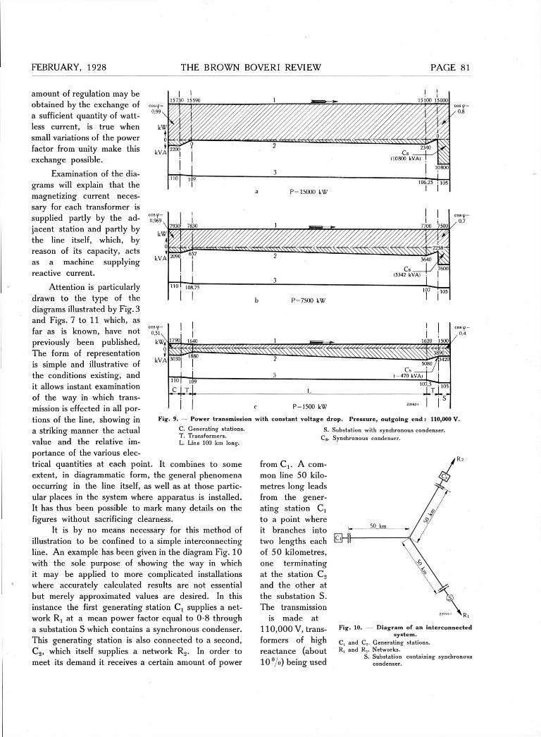
The diagrams in Fig. 9 deal, as in the preced-ing one, with the transmission of energy from a gener-ating Station to a substation. The operating pressure of the system is 110,000 V and the voltage drop in the connecting line remains constant at 5000 V. As in the previous example, Fig. 8, a synchronous condenser is provided to supply the system with magnetizing current.
Finally, Fig. 11 shows two more cases of an 87,000-V transmission between generating stations with a zero voltage drop.
From the examples given, it will be seen that the Statement made in the beginning, that the desired
FEBRUARY, 1928 THE BROWN BOVERI REVIEW PAGE
amount of regulation may be obtained by the exchange of a sufficient quantity of watt-less current, is true when small variations of the power factor from unity make this exchange possible.
Examination of the dia-grams will explain that the magnetizing current neces-sary for each transformer is supplied partly by the ad-jacent Station and partly by the line itself, which, by reason of its capacity, acts as a machine supplying reactive current.
Attention is particularly drawn to the type of the diagrams illustrated by Fig. 3 and Figs. 7 to 11 which, as far as is known, have not previously been published. The form of representation is simple and illustrative of the conditions existing, and it allows instant examination
C. Generating stations. T. Transformers. L. Line 100 km long.
of the way in which trans-mission is effected in all por-tions of the line, showing in a striking manner the actual value and the relative im-portance of the various elec-trical quantities at each point. It combines to some extent, in diagrammatic form, the general phenomena occurring in the line itself, as well as at those partic-ular places in the system where apparatus is installed. It has thus been possible to mark many details on the figures without sacrificing clearness.
It is by no means necessary for this method of illustration to be confined to a simple interconnecting line. An example has been given in the diagram Fig. 10 with the sole purpose of showing the way in which it may be applied to more complicated installations where accurately calculated results are not essential but merely approximated values are desired. In this instance the first generating Station C t supplies a net-work R( at a mean power factor equal to 0-8 through a substation S which contains a synchronous condenser. This generating Station is also connected to a second, C 2 , which itself supplies a network R 2 . In order to meet its demand it receives a certain amount of power
Fig. 9. Power transmission with constant voltage drop. Pressure, outgoing end : 110,000 V.
S. Substation with synchronous condenser. C s . Synchronous condenser.
from Cj. A com-mon line 50 kilo-metres long leads from the gener-ating Station C, to a point where it branches into two lengths each of 50 kilometres, one terminating at the Station C 2
and the other at the substation S. The transmission
is made at 110,000 V, trans-formers of high reactance (about 10°/o) being used
Fig. 10. Diagram of an interconnected system.
C, and C.. Generating stations. R, and R... Networks.
S. Substation containing synchronous condenser.

PAGE THE BROWN BOVERI REVIEW
15200 15000
. _ „ -
P = 15000 kW
Fig. 11. — P o w e r transmission with zero voltage drop. Pressure , outgoing end : 87,000 V.
C. Ge nerating stations. 1. Energy in kW. T. Transformers. 2. Wattless energy in kVA. L. Line 100 km long. 3. Pressure in kV. P. Power received at end of line.
Fig . 12. — Power transmission on a line with two branches.
C, and C 2 . Generating stations. T. Transformers.
L „ L. and Ls, Lines 50 km long. S. Substation containing synchronous condenser.
at the three ends to step up and Step down the voltage. It will be seen from the diagram in Fig. 12 that the whole of the reactive energy of the synchronous condenser is absorbed by the network R, while that required by the line and the transformers, as magnetizing current, is drawn for the most part from the generating stations Cj and C2 , and in a smaller degree from the line itself.
From the preceding con-siderations it may be rightly concluded that considerable advantage would be derived from increasing the flexibility of the circuits by means of reactances. This flexibility, as has been shown, gives an auto-matic regulation of the voltage which is advantageous in the respect that it is absolutely without interruption. Efficient operation of the total plant is likewise possible and the fore-going examples show that the apparatus, as well as the lines, may work with a high power factor, thus allowing smaller transformers to be installed. It has also been illustrated how this method of regulation re-duces the number of synchron-ous condensers and alternators required, lowering consider-ably the first costs. Lastly, the advantages should be remem-bered of distributing through-out a network a number of small transformers of high reactance, working in combination with synchronous condensers, suit-ably located in the system. It has thus been shown in the preceding, that regulation is, in principle, carried out under
Optimum conditions; the power stations, being actually relieved of the majority of their wattless energy that is requir-ed to be fumished for the system, are therefore able to operate at a high power factor. The application of these prin-ciples combined with careful calculation will result in the
best Solution. Suitable study of a network, in the way explained, will point to large economies which may be effected, and it would therefore seem that in this manner a Solution has been suggested which is both convenient and successful in its application.
(MS 459) J. Defreyn. (J. S. B.)
Pressure , outgoing e n d : 110,000 V.
1. Energy in k W . 2. Wattless energy in kVA. 3. Pressure in kV.
PAGE 83
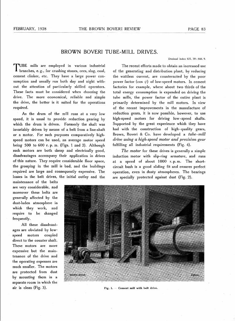
BROWN BOVERI TUBE-MILL DRIVES. Decimal index 621. 39 : 666. 9.
TUBE mills are employed in various industrial branches, e. g., for crushing stones, ores, slag, coal,
cement clinker, etc. They have a large power con-sumption and usually run both day and night with-out the attention of particularly skilled Operators. These facts must be considered when choosing the drive. The more economical, reliable and simple the drive, the better is it suited for the Operations required.
As the drum of the mill runs at a very low speed, it is usual to provide reduction gearing by which the drum is driven. Formerly the shaft was invariably driven by means of a belt from a line-shaft or a motor. For such purposes comparatively high-speed motors can be used, an average motor speed being 500 to 600 r. p. m. (Figs. 1 and 2). Although such motors are both cheap and electrically good, disadvantages accompany their application in drives of this nature. They require considerable floor space, the grouping in the mill is bad, and the buildings required are large and consequently expensive. The losses in the belt drives, the initial outlay and the maintenance of the belts are very considerable, and moreover these belts are generally affected by the dust-laden atmosphere in which they work, and require to be changed frequently.
All these disadvant-ages are obviated by low-speed motors coupled direct to the counter shaft. These motors are more expensive but the main-tenance of the drive and the operating expenses are much smaller. The motors are protected from dust by mounting them in a separate room in which the air is clean (Fig. 3). Fig.
The recent efforts made to obtain an increased use of the generating and distribution plant, by reducing the wattless current, are counteracted by the poor power factor (cos (f) of low-speed motors. In cement factories for example, where about two thirds of the total energy consumption is expended on driving the tube mills, the power factor of the entire plant is primarily determined by the mill motors. In view of the recent improvements in the manufacture of reduction gears, it is now possible, however, to use high-speed motors for driving low-speed shafts. Supported by the great experience which they have had with the construction of high-quality gears, Brown, Boveri & Co. have developed a tube-mill drive using a high-speed motor and precision gear fulfilling all industrial requirements (Fig. 4).
The motor for these drives is generally a simple induction motor with slip-ring armature, and runs at a speed of about 1000 r. p. m. The short-circuit bush is a good sliding fit and ensures perfect Operation, even in dusty atmospheres. The bearings are specially protected against dust (Fig. 2).
1. Cement mill with belt drive.

PAGE 4 THE BROWN BOVERI REVIEW FEBRUARY, 1928
I B 2 I 7 -BROWN BOVER!
Fig. 2. Three-phase motor, type MS 2810, for 255 kW, 585 r . p. m.,
with dust-proof bearings.
The Starter in low-tension plants is com-bined with the stator switch so that all switching Oper-ations for starting and stopping are effected in
the correct sequence, merely by rotating a hand-wheel. Errors in control are thus impossible and hence unskilled attendants may start or stop the
machines. Push-button control enables the motor to be stopped from the mill itself.
Brown Boveri pre-d s i o n g e a r S have Single- Fig. 3. Low-speed mill motors , i . , , , , /r->. i in a cement works.
helical teeth (rig. 5) and the constructional develop-ments of these gears have taken into consideration their application in industrial plants. The cast-iron casing which serves also as an oil reservoir, is both dust and spray-tight (Fig. 6). The pinion, which is forged in one piece with the shaft, is made from high-quality alloy steel. The wheel body is of cast iron, while the toothed rim and the shaft are of open-hearth steel. The shaft runs in either ball or roller
bearings. The high precision of the teeth ensures quiet running, small transmission losses, practically no wear on the teeth, and an exceedingly long life for the gears. The efficiency, inclusive of bearing friction, is at least 99 °/o, while that of the teeth alone amounts to about 99-7 %• The automatic lubrication is of special importance; no oil pump is needed as lubrication is effected simply by immersing the spur wheel in the oil bath. In this way the method of Operation of the drive is independent of the relia-bility of any auxiliary apparatus and the attendance is limited to the occasional checking of the oil level.
The Brown Boveri precision gear is superior to gears having either straight or double - helical tooth
profiles. Comparing spur and helical wheels, the latter have the advantage of uninterrupted meshing and the pressure on the teeth in contact does not rise immediately from zero to maximum but increases gradually to its maximum value and then uniformly diminishes, thus ensuring quiet and smooth Oper-ation. With double-helical wheels, above all, difficulty is encountered in that it is impossible to mesh on both halves of the tooth profile
simultaneously, unless some special arrangement is employed, as, even with
Fig. 4. — Tube mill drive, comprising a three-phase motor, 300 kW, 980 r . p . r a . , and precision single-helical reduction gear980/161 r . p . m .
Upper part of casing removed.
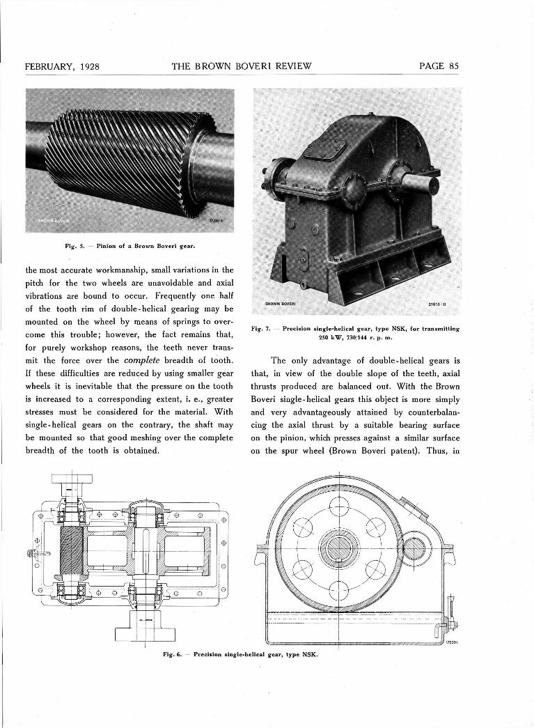
FEBRUARY, 1928 THE BROWN BOVERI REVIEW PAGE 5
mm
; 1731011
Fig. 5. Pinion of a Brown Boveri gear.
the most accurate workmanship, small variations in the pitch for the two wheels are unavoidable and axial vibrations are bound to occur. Frequently one half of the tooth rim of double-helical gearing may be mounted on the wheel by means of springs to over-come this trouble; however, the fact remains that, for purely Workshop reasons, the teeth never trans-mit the force over the complete breadth of tooth. If these difficulties are reduced by using smaller gear wheels it is inevitable that the pressure on the tooth is increased to a corresponding extent, i. e., greater stresses must be considered for the material. With Single-helical gears on the contrary, the shaft may be mounted so that good meshing over the complete breadth of the tooth is obtained.
Fig. 7. — Precision single-helical gear, type NSK, for transmitting 250 kW, 730/144 r. p. m.
The only advantage of double-helical gears is that, in view of the double slope of the teeth, axial thrusts produced are balanced out. With the Brown Boveri single-helical gears this object is more simply and very advantageously attained by counterbalan-cing the axial thrust by a suitable bearing surface on the pinion, which presses against a similar surface on the spur wheel (Brown Boveri patent). Thus, in
BROWN BOVERI 21613 • II
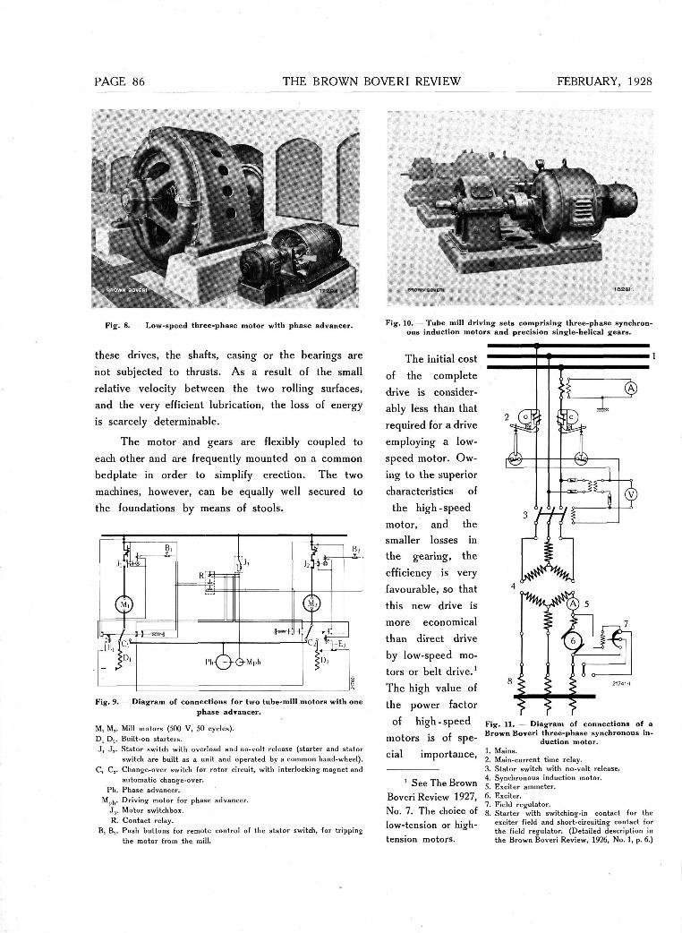
PAGE 6 THE BROWN BOVERI REVIEW FEBRUARY, 1928
« s e i
Fig. 8. Low-speed three-phase motor with phase advancer.
these drives, the shafts, casing or the bearings are not subjected to thrusts. As a result of the small relative velocity between the two rolling surfaces, and the very efficient lubrication, the loss of energy is scarcely determinable.
The motor and gears are flexibly coupled to each other and are frequently mounted on a common bedplate in order to simplify erection. The two machines, however, can be equally well secured to the foundations by means of stools.
Fig. 9.
M, M s . D, D,. J , J , .
C. C„.
Ph. Mph. J5.
R. B, Bj.
Diagram of connections for two tube-mill motors with one phase advancer.
Mill motors (500 V, 50 cycles). Built-on starters. Stator switch with overload and no-volt release (starter and stator switch are built as a unit and operated by a common hand-wheel). Change-over switch for rotor circuit, with interlocking magnet and automatic change-over. Phase advancer. Driving motor for phase advancer. Motor switchbox. Contact relay. Push buttons for remote control of the stator switch, for tripping the motor from the mill.
Fig. 10. — Tube mill driving sets comprising three-phase synchron-ous induction motors and precision single-helical gears.
The initial cost of the complete drive is consider-ably less than that required for a drive employing a low-speed motor. Ow-ing to the superior characteristics of
the high-speed motor, and the smaller losses in the gearing, the efficiency is very favourable, so that this new drive is more economical than direct drive by low-speed mo-tors or belt drive.1
The high value of the power factor
of high - speed motors is of spe-cial importance,
1 See The Brown Boveri Review 1927, No. 7. The choice of low-tension or high-tension motors.
Fig. 11. — Diagram of connections of a Brown Boveri three-phase synchronous in-
duction motor. 1. Mains. 2. Main-current time relay. 3. Stator switch with no-volt release. 4. Synchronous induction motor. 5. Exciter ammeter. 6. Exciter. 7. Field regulator. 8. Starter with switching-in contact for the
exciter field and short-circuiting contact for the field regulator. (Detailed description in the Brown Boveri Review, 1926, No. 1, p. 6.)
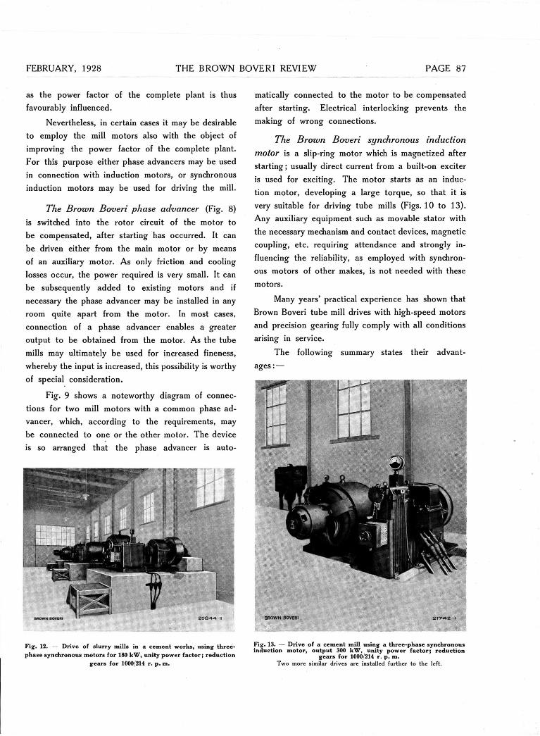
FEBRUARY, 1928 THE BROWN BOVERI REVIEW PAGE
as the power factor of the complete plant is thus favourably influenced.
Nevertheless, in certain cases it may be desirable to employ the mill motors also with the object of improving the power factor of the complete plant. For this purpose either phase advancers may be used in connection with induction motors, or synchronous induction motors may be used for driving the mill.
The Brown Boveri phase advancer (Fig. 8) is switched into the rotor circuit of the motor to be compensated, after starting has occurred. It can be driven either from the main motor or by means of an auxiliary motor. As only friction and cooling losses occur, the power required is very small. It can be subsequently added to existing motors and if necessary the phase advancer may be installed in any room quite apart from the motor. In most cases, connection of a phase advancer enables a greater Output to be obtained from the motor. As the tube mills may ultimately be used for increased fineness, whereby the input is increased, this possibility is worthy of special consideration.
Fig. 9 shows a noteworthy diagram of connec-tions for two mill motors with a common phase ad-vancer, which, according to the requirements, may be connected to one or the other motor. The device is so arranged that the phase advancer is auto-
Fig. 12. — Drive of slurry mills in a cement works, using three-phase synchronous motors for 180 kW, unity power fac tor ; reduction
gears for 1000/214 r. p. m.
matically connected to the motor to be compensated after starting. Electrical interlocking prevents the making of wrong connections.
The Brown Boveri synchronous induction motor is a slip-ring motor which is magnetized after starting; usually direct current from a built-on exciter is used for exciting. The motor starts as an induc-tion motor, developing a large torque, so that it is very suitable for driving tube mills (Figs. 10 to 13). Any auxiliary equipment such as movable stator with the necessary mechanism and contact devices, magnetic coupling, etc. requiring attendance and strongly in-fluencing the reliability, as employed with synchron-ous motors of other makes, is not needed with these motors.
Many years' practical experience has shown that Brown Boveri tube mill drives with high-speed motors and precision gearing fully comply with all conditions arising in service.
The following summary states their advant-ages: —
Fig . 13. — Drive of a cement mill using a three-phase synchronous induction motor, Output 300 kW, unity power fac tor ; reduction
gears for 1000/214 r . p. m. Two more similar drives are installed further to the left.
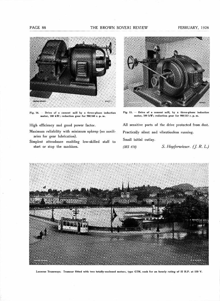
PAGE THE BROWN BOVERI REVIEW
BROWN BOVERI fr;
Fig. 14. — Drive of a cement mill by a tbree-phase induction motor, 180 k W ; reduction gear for 980 160 r. p. m.
High efficiency and good power factor.
Maximum reliability with minimum upkeep (no auxiii-aries for gear lubrication).
Simplest attendance enabling low-skilled staff to start or stop the machines.
Fig. 15. — Drive of a cement mill, by a three-phase induction motor, 180 k W ; reduction gear for 980/112 r. p. m.
All sensitive parts of the drive protected from dust.
PracticaUy silent and vibrationless running.
Small initial outlay.
(MS 418) S. Hopf erwieser. (J. R. L.)
Lucerne Tramways. Tramcar fitted with two totally-enclosed motors, type GTM, each for an hourly rating- of 52 H.P. at 550 V.
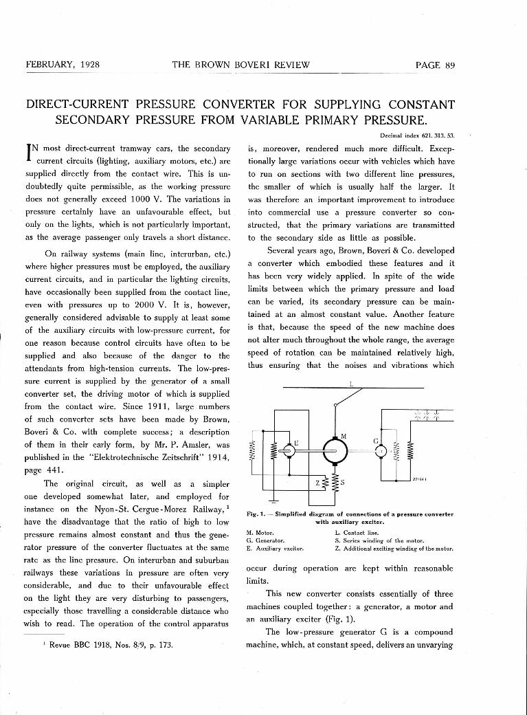
FEBRUARY, 1928 THE BROWN BOVERI REVIEW PAGE
DIRECT-CURRENT PRESSURE CONVERTER FOR SUPPLYING CONSTANT SECONDARY PRESSURE FROM VARIABLE PRIMARY PRESSURE.
Decimal index 621. 313. 53.
TN most direct-current tramway cars, the secondary current circuits (lighting, auxiliary motors, etc.) are
supplied directly from the contact wire. This is un-doubtedly quite permissible, as the working pressure does not generally exceed 1000 V. The variations in pressure certainly have an unfavourable effect, but only on the lights, which is not particularly important, as the average passenger only travels a short distance.
On railway systems (main line, interurban, etc.) where higher pressures must be employed, the auxiliary current circuits, and in particular the lighting circuits, have occasionally been supplied from the contact line, even with pressures up to 2000 V. It is, however, generally considered advisable to supply at least some of the auxiliary circuits with low-pressure current, for one reason because control circuits have often to be supplied and also because of the danger to the attendants from high-tension currents. The low-pres-sure current is supplied by the generator of a small Converter set, the driving motor of which is supplied from the contact wire. Since 1911, large numbers of such Converter sets have been made by Brown, Boveri & Co. with complete success; a description of them in their early form, by Mr. P. Amsler, was published in the "Elektrotechnische Zeitschrift" 1914, page 441.
The original circuit, as well as a simpler one developed somewhat later, and employed for instance on the Nyon-St. Cergue-Morez Railway,1
have the disadvantage that the ratio of high to low pressure remains almost constant and thus the gene-rator pressure of the Converter fluctuates at the same rate as the line pressure. On interurban and suburban railways these variations in pressure are often very considerable, and due to their unfavourable effect on the light they are very disturbing to passengers, especially those travelling a considerable distance who wish to read. The Operation of the control apparatus
1 Revue BBC 1918, Nos. 8/9, p. 173.
is, moreover, rendered much more difficult. Excep-tionally large variations occur with vehicles which have to run on sections with two different line pressures, the smaller of which is usually half the larger. It was therefore an important improvement to introduce into commercial use a pressure Converter so con-
structed, that the primary variations are transmitted to the secondary side as little as possible.
Several years ago, Brown, Boveri & Co. developed a Converter which embodied these features and it has been very widely applied. In spite of the wide limits between which the primary pressure and load can be varied, its secondary pressure can be main-tained at an almost constant value. Another feature is that, because the speed of the new machine does not alter much throughout the whole ränge, the average speed of rotation can be maintained relatively high, thus ensuring that the noises and vibrations which
Fig. 1. — Simplified diagram of connections of a pressure Converter with auxiliary exci ter .
M. Motor. L. Contact line. G. Generator. S. Series winding of the motor. E. Auxiliary exciter. Z. Additional exciting winding of the motor.
occur during Operation are kept within reasonable
limits.
This new Converter consists essentially of three machines coupled together: a generator, a motor and an auxiliary exciter (Fig. 1).
The low-pressure generator G is a Compound
machine, which, at constant speed, delivers an unvarying

PAGE THE BROWN BOVERI REVIEW FEBRUARY, 1928
pressure, independent of the load. The motor M must therefore run as nearly as possible at constant speed under all Service conditions.
With respect to the good starting conditions for the group and as a protection against flash-over, the motor must be provided with a strong series winding. When the generator is on füll load and when the primary pressure is lowest, this winding alone would be sufficient to excite the motor fully. On increasing the primary pressure or decreasing the load, this excitation no longer suffices to maintain the field which is neces-sary to keep the speed constant. The motor is con-sequently provided with a second exciting winding which is supplied from the auxiliary exciter machine already mentioned. Thus the discrepancy in the ampere-turns is made up. This exciter is a compound-wound generator having, besides the usual shunt winding, an additional field winding through which the motor current flows. The latter winding ensures that the correct excitation is obtained at starting.
It is obvious from Fig. 2 how the procedure already mentioned takes place. The curves 1, 2, and 3 show the relation between the pressure of the auxiliary exciter and its excitation at various speeds of revolu-tion; 1 is for the normal speed, 2 for a somewhat higher and 3 is for a somewhat lower speed. For clear-
2
1 3
Fig. 2. — Curves showing the relationship between the terminal pressure of the auxiliary exciter and its excitation at different speeds.
Abscissae: Exciting current (or excitation in AT) of the auxiliary exciter. Ordinates: Terminal pressure of the auxiliary exciter.
ness, the pressure curves, which actually are very close together, have been widely separated from one another. The direction 4 indicates the pressure required to over-come the resistance of the shunt exciting winding. As is common knowledge, the pressure of a self-excited machine is given by the point of intersection of this "resistance vector" with the pressure curve for the given speed. The "critical ränge of speed" for seif excitation is a narrowly confined region in which the field, prod-uced directly by seif excitation, is particularly unstable and may be greatly influenced by small speed varia-tions. If the resistance vector falls within this ränge, a very small drop in speed below a certain value makes the field practically disappear, while a very small increase in speed causes the field and the pres-sure of the machine to reach the upper limits of the region.
Now the auxiliary exciter is so constructed that its resistance vector falls in that part of the critical speed region where both the limiting pressure curves are practically straight lines. (Terminal points B and C in Fig. 2). These two limit curves lie very near to each other. Thus the speed can vary only very slightly either above or below the desired value, which is approximately in the middle of the critical ränge, without causing the pressure to disappear or the maximum value to be attained.
The auxiliary exciter is connected so that its pressure Variation always produces a current which opposes the speed fluctuation of the driving machine. At the normal motor speed, for instance, the auxiliary exciter machine gives a pressure corresponding to the point A, Fig. 2. This pressure causes an additional field in the exciter winding Z of the driving motor M, and this, together with that of the series winding S, corresponds, at normal pressure and füll load, to the desired normal speed. If now the motor pressure in-creases, or the load on the generator decreases, the field of the motor is no longer sufficient to ensure the maintenance of the desired speed. The increase in speed which then commences, is, however, im-mediately checked, because, as soon as the armature of the auxiliary exciter begins to rotate at increased speed, the pressure of this machine, and also the current in the winding Z of the motor, rise rapidly. In Fig. 2, for example, the point B corresponds to the conditions when the Converter is running on no-load and the highest motor pressure obtains. If the rise in the
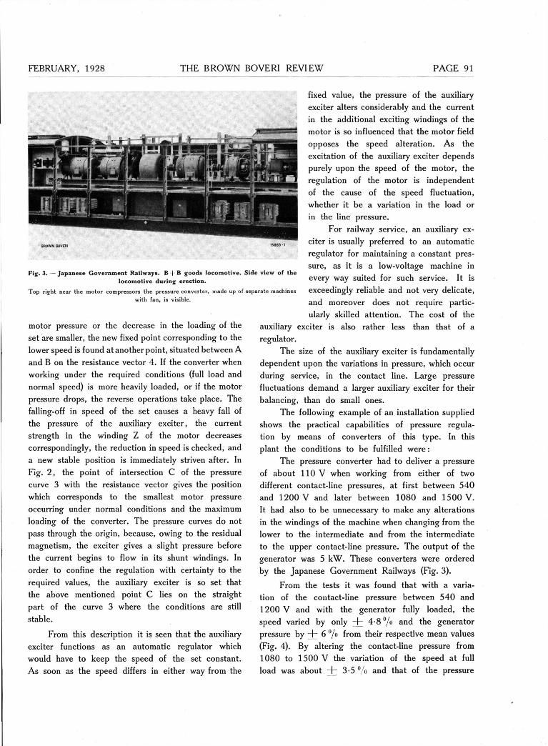
FEBRUARY, 1928 THE BROWN BOVERI REVIEW PAGE
Fig. 3. — Japanese Government Railways. B + B goods locomotive. Side view of the locomotive during erection.
Top right near the motor compressors the pressure Converter, made up of separate machines with fan, is visible.
motor pressure or the decrease in the loading of the set are smaller, the new fixed point corresponding to the lower speed is found at another point, situated between A and B on the resistance vector 4. If the Converter when working under the required conditions (füll load and normal speed) is more heavily Ioaded, or if the motor pressure drops, the reverse Operations take place. The falling-off in speed of the set causes a heavy fall of the pressure of the auxiliary exciter, the current strength in the winding Z of the motor decreases correspondingly, the reduction in speed is checked, and a new stable position is immediately striven after. In Fig. 2, the point of intersection C of the pressure curve 3 with the resistance vector gives the position which corresponds to the smallest motor pressure occurring under normal conditions and the maximum loading of the Converter. The pressure curves do not pass through the origin, because, owing to the residual magnetism, the exciter gives a slight pressure before the current begins to flow in its shunt windings. In order to confine the regulation with certainty to the required values, the auxiliary exciter is so set that the above mentioned point C lies on the straight part of the curve 3 where the conditions are still stable.
From this description it is seen that the auxiliary exciter functions as an automatic regulator which would have to keep the speed of the set constant. As soon as the speed differs in either way from the
fixed value, the pressure of the auxiliary exciter alters considerably and the current in the additional exciting windings of the motor is so influenced that the motor field opposes the speed alteration. As the excitation of the auxiliary exciter depends purely upon the speed of the motor, the regulation of the motor is independent of the cause of the speed fluctuation, whether it be a Variation in the load or in the line pressure.
For railway Service, an auxiliary ex-citer is usually preferred to an automatic regulator for maintaining a constant pres-sure, as it is a low-voltage machine in every way suited for such Service. It is exceedingly reliable and not very delicate, and moreover does not require partic-ularly skilled attention. The cost of the
auxiliary exciter is also rather less than that of a regulator.
The size of the auxiliary exciter is fundamentally dependent upon the variations in pressure, which occur during Service, in the contact line. Large pressure fluctuations demand a larger auxiliary exciter for their balancing, than do small ones.
The following example of an installation supplied shows the practical capabilities of pressure regula-tion by means of Converters of this type. In this plant the conditions to be fulfilled were:
The pressure Converter had to deliver a pressure of about 110 V when working from either of two different contact-line pressures, at first between 540 and 1200 V and later between 1080 and 1500 V. It had also to be unnecessary to make any alterations in the windings of the machine when changing from the lower to the intermediate and from the intermediate to the upper contact-line pressure. The Output of the generator was 5 kW. These Converters were ordered by the Japanese Government Railways (Fig. 3).
From the tests it was found that with a Varia-tion of the contact-line pressure between 540 and 1200 V and with the generator fully Ioaded, the speed varied by only + 4-8 °/o and the generator pressure by nh 6 °/o from their respective mean values (Fig. 4). By altering the contact-line pressure from 1080 to 1500 V the Variation of the speed at füll load was about + 3-5 °/o and that of the pressure
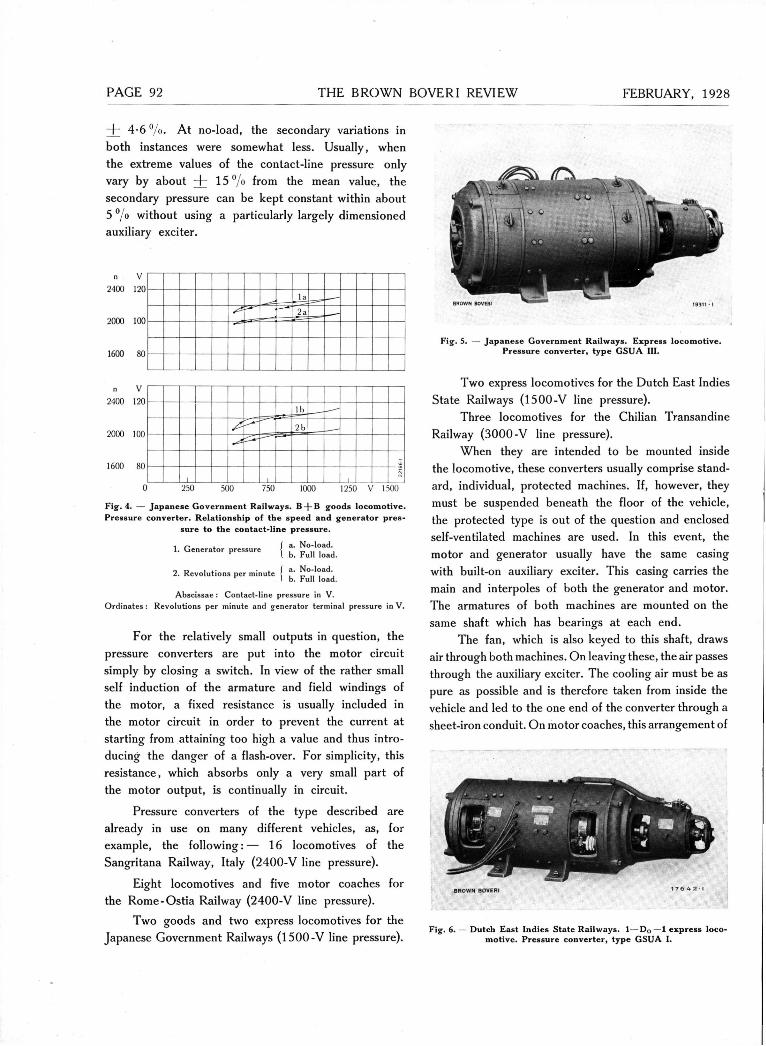
PAGE THE BROWN BOVERI REVIEW FEBRUARY, 1928
I 4 - 6 % . At no-load, the secondary variations in both instances were somewhat less. Usually, when the extreme values of the contact-line pressure only vary by about + 1 5 % from the mean value, the secondary pressure can be kept constant within about 5°/o without using a particularly largely dimensioned auxiliary exciter.
1600 80
n V 2400 120
2000 100
1600 80
lb
2b
-1 -
0 250 500 750 1000 1250 V 1500
Fig. 4. — Japanese Government Railways. B - ) - B goods locomotive. Pressure C o n v e r t e r . Relationship of the speed and generator pres-
sure to the contact-line pressure.
a. No-load. b. Füll load.
1. Generator pressure
, .. . I a. No-load. 2. Revolutions per mmute I b. Füll load.
Abscissae : Contact-line pressure in V. Ordinates : Revolutions per minute and generator terminal pressure in V.
For the relatively small Outputs in question, the pressure Converters are put into the motor circuit simply by closing a switch. In view of the rather small seif induction of the armature and field windings of the motor, a fixed resistance is usually included in the motor circuit in order to prevent the current at starting from attaining too high a value and thus intro-ducing the danger of a flash-over. For simplicity, this resistance, which absorbs only a very small part of the motor Output, is continually in circuit.
Pressure Converters of the type described are already in use on many different vehicles, as, for example, the following:— 16 locomotives of the Sangritana Railway, Italy (2400-V line pressure).
Eight locomotives and five motor coaches for the Rome-Ostia Railway (2400-V line pressure).
Two goods and two express locomotives for the Japanese Government Railways (1500-V line pressure).
brown boveri
Fig. 5. — Japanese Government Railways. Express locomotive. Pressure C o n v e r t e r , type GSUA III.
Two express locomotives for the Dutch East Indies State Railways (1500-V line pressure).
Three locomotives for the Chilian Transandine Railway (3000-V line pressure).
When they are intended to be mounted inside the locomotive, these Converters usually comprise Stand-ard, individual, protected machines. If, however, they must be suspended beneath the floor of the vehicle, the protected type is out of the question and enclosed self-ventilated machines are used. In this event, the motor and generator usually have the same casing with built-on auxiliary exciter. This casing carries the main and interpoles of both the generator and motor. The armatures of both machines are mounted on the same shaft which has bearings at each end.
The fan, which is also keyed to this shaft, draws air through both machines. On leaving these, the air passes through the auxiliary exciter. The cooling air must be as pure as possible and is therefore taken from inside the vehicle and led to the one end of the Converter through a sheet-iron conduit. On motor coaches, this arrangement of
8ROWN BOVERI 1 t 6 4 2 i
Fig. 6. — Dutch East Indies State Railways. 1 — D 0 — 1 e x p r e s s loco-m o t i v e . Pressure C o n v e r t e r , t y p e GSUA I.
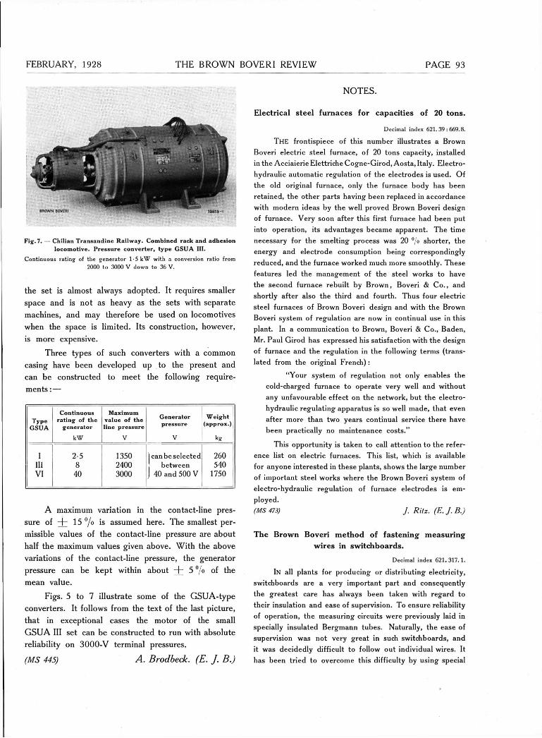
FEBRUARY, 1928 THE BROWN BOVERI REVIEW
Fig. 7. — Chilian Transandine Railway. Combined rack and adhesion l o c o m o t i v e . Pressure C o n v e r t e r , t y p e GSUA HI.
Continuous rating of the generator 1-5 kW with a conversion ratio from 2000 to 3000 V down to 36 V.
the set is almost always adopted . It requires smaller
space and is not as heavy as the sets with separa te
machines, and may therefore be used on locomotives
when the spa ce is limited. Its construction, however,
is more expensive.
Three types of such Converters with a c o m m o n
casing have been developed up to the present and
can be constructed to m e e t the following require-
m e n t s : —
Type GSUA
Continuous rating of the
generator
kW
Maximum value of the line pressure
V
Generator pressure
V
Weight (approx.)
kg
I 2-5 1350 1 canbeselected 260 III 8 2400 between 540 VI 40 3000 J 40 and 500 V
1750
A maximum Variation in the contac t - l ine pres-
sure of + 15°/o is a ssumed here . T h e smal lest per-
missible values of the c o n t a c t - l i n e pressure are a b o u t
half the maximum values given a b o v e . W i t h the a b o v e
variat ions of the c o n t a c t - l i n e pressure, the g e n e r a t o r
pressure can b e k e p t within a b o u t I 5 °/o of the
mean va lue .
F i g s . 5 to 7 i l lustrate s o m e of the G S U A - t y p e
Converters. It fo l lows f rom the tex t of the last p ic ture ,
t h a t in except ional c a s e s the m o t o r of the small
G S U A III se t can b e c o n s t r u c t e d t o run with a b s o l u t e
rel iabi l i ty on 3 0 0 0 - V terminal pressures .
(MS 445) A. Brodbeck. (E. J. B.)
PAGE
N O T E S .
Elec t r i ca l s teel f u r n a c e s for c a p a c i t i e s of 20 t o n s .
Decimal index 621.39 : 669.8.
THE frontispiece of this number illustrates a Brown Boveri electric steel furnace, of 20 tons capacity, installed in the Acciaierie Elettriche Cogne-Girod, Aosta, Italy. Electro-hydraulic automatic regulation of the electrodes is used. Of the old original furnace, only the furnace body has been retained, the other parts having been replaced in accordance with modern ideas by the well proved Brown Boveri design of furnace. Very soon after this first furnace had been put into operation, its advantages became apparent. The time necessary for the smelting process was 20 °/o shorter, the energy and electrode consumption being correspondingly reduced, and the furnace worked much more smoothly. These features led the management of the steel works to have the second furnace rebuilt by Brown, Boveri & Co. , and shortly after also the third and fourth. Thus four electric steel furnaces of Brown Boveri design and with the Brown Boveri system of regulation are now in continual use in this plant. In a communication to Brown, Boveri & Co., Baden, Mr. Paul Girod has expressed his satisfaction with the design of furnace and the regulation in the following terms (trans-lated from the original French):
"Your system of regulation not only enables the cold-charged furnace to operate very well and without any unfavourable effect on the network, but the electro-hydraulic regulating apparatus is so well made, that even after more than two years continual Service there have been practically no maintenance costs."
This opportunity is taken to call attention to the refer-ence list on electric furnaces. This list, which is available for anyone interested in these plants, shows the large number of important steel works where the Brown Boveri system of electro-hydraulic regulation of furnace electrodes is em-ployed.
(MS 473) J. Ritz. (E.J.B.)
T h e B r o w n B o v e r i m e t h o d of f a s t e n i n g m e a s u r i n g
w i r e s in s w i t c h b o a r d s .
Decimal index 621.317.1 .
IN all plants for producing or distributing electricity, switchboards are a very important part and consequently the greatest care has always been taken with regard to their insulation and ease of supervision. To ensure reliability of operation, the measuring circuits were previously laid in specially insulated Bergmann tubes. Naturally, the ease of supervision was not very great in such switchboards, and it was decidedly difficult to follow out individual wires. It has been tried to overcome this difficulty by using special

PAGE 94 THE BROWN BOVERI REVIEW FEBRUARY, 1928
BROWN BOVERI
Fig. 1. — Rear v i e w o f a S w i t c h b o a r d s h o w i n g - t h e m e t h o d o f
w i t h c l a m p s .
rubber-insulated wires, which can be laid without further protection. Naturally, these wires must not be led for any desired distance without supports. Brown, Boveri & Co. now lay such wires by a patented method, in which the wires are fixed to strips of iron by means of special clamps. Fig. 1 shows a switchboard laid out in this manner. It is part of a signalling system such as is now found in all modern power stations. In spite of the large number of connections, the clear arrangement of the wires and neat appearance of such an installation are easily Seen from the illustration. The advantages over all other methods whicli the use of clamps secures are, besides the better facilities for supervision, the simplicity of erection, the ease with which the wires can be changed, and last, but not least, the strength of the whole arrangement. For short lengths, sufficient stiff-ness of the wires is obtained if they are merely bound together with clamps into a bündle and led along the switchboard without other means of support. Side by side with the ease of handling which is obtained by the use of clamps, is a corresponding reduction in the cost of erection.
Where for special reasons an exceptionally good insul-ation of the measuring circuits from earth is required, the fixing of the wires with clamps enables this to be obtained by using inter-layers of presspan.
In conclusion, it should be pointed out that a partic-ular advantage of. the clamps used by Brown, Boveri & Co. is that no screws whatever are necessary. The two parts
A description of the new B - B locomotives for local, passenger and goods Service on the Oslo-Lilleström section of the Norwegian State Rail-ways is given in the A E G Mitteilungen, No. 5, 1927. It is of interest to mention that all the driving motors of these locomotives are of Brown Boveri design and were built in the Workshops of the Norsk
securing the measuring wires Elektrisk & Brown Boveri at
Oslo. They are Single-phase series motors for 16 2/s cycles
of the E L M 100 a 16 type, and designed for the follow-ing conditions:—
One-hour rating at the motor shaft: 700 H.P. (515 k W ) ;
380 V, 575 r. p. m.
Continuous rating at the motor shaft: 572 H.P. (425 k W ) ;
355 V, 575 r. p. m.
The maximum speed during Service is 918 r. p. m. The motors have sixteen poles and are fitted with forced Ven-tilation. The particulars relating to the Output of the motors conform to the regulations of the A. I. E . E. for stationary machines.
The stators of the motors are not fitted with divided compensating windings; this is particularly noteworthy with single-phase traction motors of such large dimensions and Outputs. A concentrated exciter winding and a concentrated winding on the interpoles are mounted in the same stator slots of the main poles; the latter winding is nearer to the rotor than the former, and thus its effect is increased.
The stator winding, just described, is an innovation for motors of this size. It is suitable and advantageous for motors having a relatively large length of active iron and a large number of poles, and hence a small pole pitch. Brown, Boveri & Co. have patented this construction in Switzerland, and patents have been applied for in other countries. At present, 160 motors of this type are in Service on express locomotives of the Swiss Federal Railways; the Operation results have been excellent.
are of bent, sheet-iron stamp-ings and can be closed-in by a slight pressure. (MS 462) W. Schaffner. (E. J. B.)
The electric locomotives for the Oslo Lilleström Railway.
Decimal index 621. 334. 2 (48. 1).

FEBRUARY, 1928 THE BROWN BOVERI REVIEW PAGE 5
The general design of the motors is particularly simple. It varies from that of the usual direct-current motor only in having a laminated field and the large number of poles when considering the rating. All connections of the wind-ings of the field, exciter and interpoles are on the opposite side to the commutator. All windings on the stator and rotor are insulated with silk and mica.
The axial load for the Oslo-Lilleström locomotives was to be 17-2 tons. The weight of the two driving mo-tors of a locomotive under no circumstances was to exceed 13 tons. The weight per motor is 6-2 tons, or 8 -9 kg per H. P. of the one hour rating; this weight is exclusive of the gear wheels and blower set, and is considered to be very small. (MS 465) E. Schröder. (J. R. L.)
Fig. 1. — Single-phase traction motor, 515 k W one-hour rating.
Puidoux Outdoor Substation of the Swiss Federal Railways. Transporting a 9000-kVA transformer ready for service. Ratio of transformation 66,000/132,000 V, 162/s cycles. Weight 83 tons.
Published by BROWN, BOVERI & COMPANY, LIMITED, BADEN (Switzerland). Printed by Kreis & Co., Basle, Switzerland.
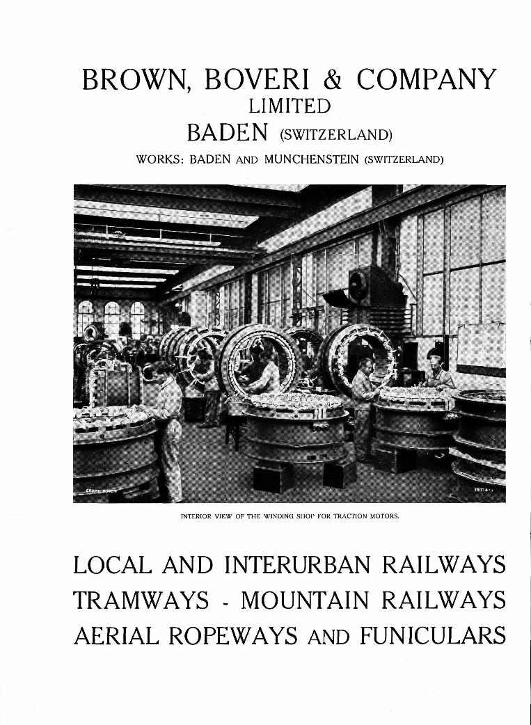
BROWN, BOVERI & COMPANY LIMITED
BADEN (SWITZERLAND) WORKS: BADEN AND MUNCHENSTEIN ( S W I T Z E R L A N D )
INTERIOR VIEW OF THE WINDING SHOP FOR TRACTION MOTORS.
LOCAL AND INTERURBAN RAILWAYS TRAMWAYS - MOUNTAIN RAILWAYS AERIAL ROPEWAYS AND FUNICULARS
Related Documents