16 GEAR SOLUTIONS • JANUARY 2004 • gearsolutionsonline.com BASICS THE REBUILDIING MACHINE TOOLS OF By Kenneth Flowers Why retire a perfectly good machine tool that may still provide years of useful service life? The following is a step-by-step outline of “How to make cents out of it.”

Welcome message from author
This document is posted to help you gain knowledge. Please leave a comment to let me know what you think about it! Share it to your friends and learn new things together.
Transcript
16 GEAR SOLUTIONS • JANUARY 2004 • gearsolutionsonline.com
BASICSTHE
REBUILDIINGMACHINE TOOLS
OF
By Kenneth Flowers
Why retire a perfectly goodmachine tool that may stillprovide years of useful service life? The following isa step-by-step outline of“How to make cents out of it.”
RRebuilding a machine tool requires expert-ise in mechanical, hydraulic, lubrication,pneumatic, electrical, control, and coolantsystems, as well as knowledge of the processthe machine performs. The rebuildingprocess will require each of these systems tobe disassembled, cleaned, inspected, andrepaired or replaced as required. A com-plete rebuild process takes place in a seriesof steps, depending on the machine and itscomplexity. But, generally speaking, theprocess follows these basic steps.
1) Disassembly, cleaning, and inspection.2) Engineering of software, electrical,
mechanical, and fluid systems.3) Ordering of the required parts.4) Machine rebuilding.
• Rescrape or regrind guide-ways, realignment verifica-tion of the slides.
• Subassembly and electricalcabinet build.
• Electrical and fluid systembuild and installation.
• Painting of the machine, in
its disassembled state.• Reassembly of the machine.
5) Startup and debug.6) Mechanical recertification.7) Test cycling and initial test cutting.8) Runoff and final testing.
Obviously, there is a significant numberof details within each of the steps outlinedabove, and a small book could easily be
devoted to the actual rebuilding process,but I will limit my discussion to a few keyareas that I feel are among the mostimportant in the rebuild process.
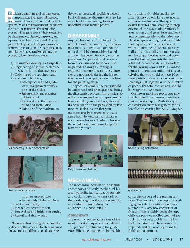
DISASSEMBLYAny machine which is to be totallyrebuilt should be completely disassem-bled into its individual parts. All theparts should be thoroughly cleanedand then inspected for wear, or otherproblems. No parts should be over-looked, or assumed to be okay andneglected. Thorough cleaning isrequired to insure that minute deficien-cies are noticeable during the inspec-tion, as well as to prepare the machinefor the painting phase.
To speed reassembly, the parts shouldbe categorized and photographed duringthe disassembly process. This simple stepwill save countless hours of questioninghow something goes back together afterit’s been sitting on the parts shelf for twomonths. It also insures that yourmachine goes back together just as itcame from the original manufacturer,not in some backward fashion, becausethe rebuilder did not know the properreassembly order.
MECHANICALThe mechanical portion of the rebuildencompasses not only mechanical butalso hydraulic, lubrication, pneumatic,and coolant systems. Within each ofthese subcategories there are some keyareas which should always beaddressed in a good rebuild.
GUIDEWAYSThe machine guideways are one of themost important aspects of the rebuild.The process for refinishing the guide-ways differs, depending on the machine
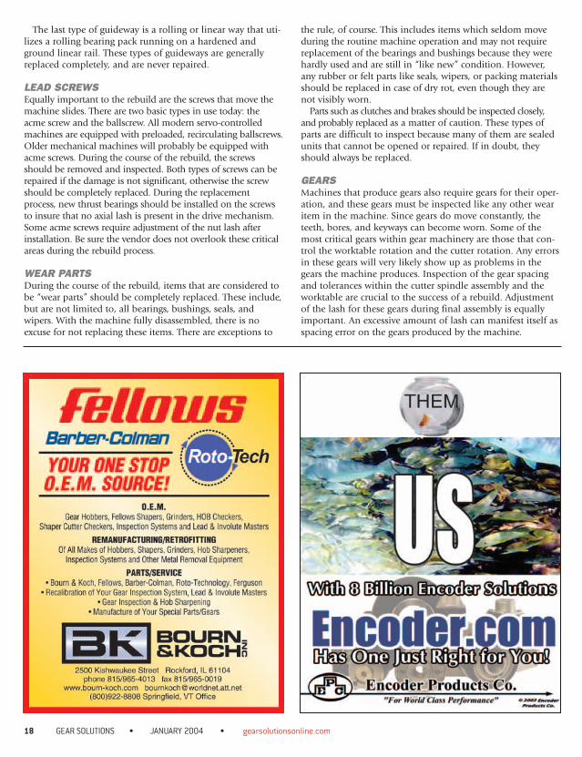
construction. On older machinery,many times you will have cast iron oncast iron construction. This type ofdesign requires hand scraping to prop-erly match the two mating surfaces foreven contact, and to achieve parallelismand perpendicularity to the other ways.Hand scraping is a highly skilled tradethat requires years of experience atwhich to become proficient. Two keyindicators of a quality scraped surfaceare the proper bearing area and pattern,plus the final alignments that areachieved. A commonly used standardfor the bearing area is 10 to 15 contactpoints in one square inch, and it is con-ceivable that you could achieve 40 ormore points, by a series of repeated finescrapings. But, regardless of the numberof points, the total contact area shouldbe roughly 50-60 percent.
On newer machine tools, you mayfind hardened and ground guidewaysthat are not scraped. With this type ofconstruction there will generally be alow friction coating like SKC3, Moglice,
or Turcite on one of the mating sur-faces. This low friction compound slid-ing against the smooth ground waysurface has a very low coefficient offriction. This is highly desirable, espe-cially on servo-controlled axes, wherestick slip can be a problem. The lowfriction coatings can be replaced ifrequired, and the ways reground forfinish and alignment.
gearsolutionsonline.com • JANUARY 2004 • GEAR SOLUTIONS 17
Subassembly, fully disassembled
Hand scraped surface
Recirculating ball screw
Acme screw
Fully disassembled bed
The last type of guideway is a rolling or linear way that uti-lizes a rolling bearing pack running on a hardened andground linear rail. These types of guideways are generallyreplaced completely, and are never repaired.
LEAD SCREWSEqually important to the rebuild are the screws that move themachine slides. There are two basic types in use today: theacme screw and the ballscrew. All modern servo-controlledmachines are equipped with preloaded, recirculating ballscrews.Older mechanical machines will probably be equipped withacme screws. During the course of the rebuild, the screwsshould be removed and inspected. Both types of screws can berepaired if the damage is not significant, otherwise the screwshould be completely replaced. During the replacementprocess, new thrust bearings should be installed on the screwsto insure that no axial lash is present in the drive mechanism.Some acme screws require adjustment of the nut lash afterinstallation. Be sure the vendor does not overlook these criticalareas during the rebuild process.
WEAR PARTSDuring the course of the rebuild, items that are considered tobe “wear parts” should be completely replaced. These include,but are not limited to, all bearings, bushings, seals, andwipers. With the machine fully disassembled, there is noexcuse for not replacing these items. There are exceptions to
the rule, of course. This includes items which seldom moveduring the routine machine operation and may not requirereplacement of the bearings and bushings because they werehardly used and are still in “like new” condition. However,any rubber or felt parts like seals, wipers, or packing materialsshould be replaced in case of dry rot, even though they arenot visibly worn.
Parts such as clutches and brakes should be inspected closely,and probably replaced as a matter of caution. These types ofparts are difficult to inspect because many of them are sealedunits that cannot be opened or repaired. If in doubt, theyshould always be replaced.
GEARSMachines that produce gears also require gears for their oper-ation, and these gears must be inspected like any other wearitem in the machine. Since gears do move constantly, theteeth, bores, and keyways can become worn. Some of themost critical gears within gear machinery are those that con-trol the worktable rotation and the cutter rotation. Any errorsin these gears will very likely show up as problems in thegears the machine produces. Inspection of the gear spacingand tolerances within the cutter spindle assembly and theworktable are crucial to the success of a rebuild. Adjustmentof the lash for these gears during final assembly is equallyimportant. An excessive amount of lash can manifest itself asspacing error on the gears produced by the machine.
18 GEAR SOLUTIONS • JANUARY 2004 • gearsolutionsonline.com
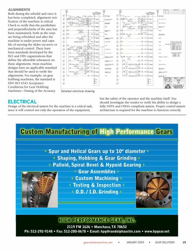
ALIGNMENTSBoth during the rebuild and once ithas been completed, alignment veri-fication of the machine is critical.Check to verify that the parallelismand perpendicularity of the axes hasbeen maintained, both as the waysare being refinished and after themachine is under power and capa-ble of moving the slides via servo ormechanical control. There havebeen standards developed by theISO and DIN organizations thatdefine the allowable tolerances onthese alignments. Most machinedesigns have an applicable standardthat should be used to verify thealignments. For example, on gearhobbing machines, the standard isDIN ISO 6545 AcceptanceConditions for Gear HobbingMachines—Testing of the Accuracy.
ELECTRICALDesign of the electrical system for the machine is a critical task,since it will control not only the operation of the equipment,
but the safety of the operator and the machine itself. Youshould investigate the vendor to verify his ability to design afully NFPA and OSHA compliant system. Proper control systemarchitecture is required for the machine to function correctly
gearsolutionsonline.com • JANUARY 2004 • GEAR SOLUTIONS 19
Detailed electrical drawing
Custom Manufacturing of High Performance Gears
Spur and Helical Gears up to 10" diameterShaping, Hobbing & Gear Grinding
Palloid, Spiral Bevel & Hypoid GearingGear Assemblies
Custom MachiningTesting & InspectionO.D. / I.D. Grinding
HIGH PERFORMANCE GEAR, INC.2119 FM 1626 • Manchaca,TX 78652
Ph: 512-292-9148 • Fax: 512-280-0678 • Email: [email protected] • www.hpgear.net
and be safe to operate. The standards set down by OSHA andthe National Fire Protection Agency—NFPA 70 NationalElectrical Code and NFPA 79 Electrical Standard for IndustrialMachinery—are designed to supply the controls engineer withall the proper codes and regulations for a safe design. If yourvendor does not use these standards, you should considerselecting another vendor.
Your electrical design should be done on a CAD system,rather than the old technique of hand drawing. It should bea thorough design, complete with identification numbers fordevices, wire numbers, colors, sizes, and stock lists.
GENERAL CONTROLSYou have a choice in the selection of the general controls foryour machinery. You can request the vendor to use AllenBradley, Siemens, GE, or Square D equipment on yourmachine. Investigate the local sources you have for replacementparts and choose a manufacturer that has local stock. Bear inmind that a vendor may be able to offer you a much betterprice by selecting a certain manufacturer. This is more often thedriving factor behind the vendor’s choice of a particular manu-facturer, instead of a technical reason.
CNC OR PLC CONTROLSGenerally speaking, the vendor will choose a PLC (ProgrammableLogic Controller) or CNC (Computer Numerical Control),based upon its capabilities. This is usually the case with gear
machinery, because of the unique requirements these machineshave. However, there is still some room for selecting a differentmanufacturer. There are just a few manufacturers of CNC con-trollers that are applicable to a fully servo-controlled gearmachine to be found in this country. These include NUM,Siemens, GE Fanuc, BWO, and Allen Bradley. Of these five,Siemens and GE Fanuc are probably the best known. Althoughnot as widely known, BWO (produced in Germany) and NUMCNCs (produced by Group Schneider, in France) are very pow-erful and economical systems that are easily applied on thesimplest or most complex gear machinery. The presence ofAllen Bradley CNCs on gear machines has dropped off signifi-cantly in recent years, and many new machine manufacturersor rebuilders do not commonly apply them.
Generally, the CNC manufacturer and model does not play asignificant role in the final performance of the machine, unlessa very specific feature like automatic stock division, synchro-nous tangential compensation, or custom interpolation isrequired. When these types of special features are required,some manufacturers have an edge over others, depending onthe features needed. Your vendor should consider the require-ments and choose the best control for the application.
SERVO SYSTEMSAn often-overlooked part of the control package is the servosystem. The servos are the muscle behind the CNC’s com-mands. I say “often overlooked” because so much emphasis
20 GEAR SOLUTIONS • JANUARY 2004 • gearsolutionsonline.com
Focused on Quality and a commitment to 100% customer satisfaction, C-B Gear
& Machine, Inc. has designed a Quality System within the guidelines of
ISO 9000. Our complete machining and gear cutting capabilities provide for
effective processing and quality control, as well as reduced lead times. Our
repair and rebuild department will perform a complete inspection and issue a
report accompanied by a recommendation and quotation.
C-B Gear & Machine, Inc.4232 MOONEY ROAD • HOUSTON, TX 77093
1-800-428-6028 281-449-0777 FAX 281-590-9127EMAIL US AT [email protected]
OR VISIT OUR WEBSITE AT WWW.CBGEAR.COM
A PROVEN PROCESS FOR THE HIGHEST REQUIREMENTS
MACHINING/TURNING/CRANE • HOBBING (SPUR, SINGLE & DOUBLE HELICAL) •
HERRINGBONE • WORMS & WORM GEARS • INTERNAL GEARS • STRAIGHT BEVEL GEARS •
INTERNAL & EXTERNAL SPLINES • SPROCKETS (ROLLER & SILENT CHAIN)
is usually placed on the CNC that the servos are somethingof an afterthought. There is at least one driving force behindthis neglect: Most people assume that the CNC manufactur-er will also be supplying the servo drives and motors. This isnot always the case. When you are considering using NUMor Siemens, for example, you have the choice of using theirservos or choosing servos from another manufacturer suchas Indramat. However, if you are considering using a GE
Fanuc system, you will discover that the GE Fanuc CNCmust be coupled with GE Fanuc servos. Although there areexceptions, 90 percent of the time this is the case.
Not all servos are created equal. Performance, adjustability,and reliability are key factors in the selection of the servo sys-tem. The motors must have the proper torque and speed tomove the axes at the required accelerations and speeds. Theservo drives should have sufficient amperage for the motorsand enough tuning parameters to correct for a variety ofissues such as inertia mismatches, lash, and inherent responsefrequencies of the machine, plus full PID loop control. Themotors and drives must also be highly reliable to insure theywill survive the hottest summer days and will not succumb tothe dirt, oil, and coolant contamination that is so commonin many shops.
SOFTWARESoftware is probably the most underestimated aspect of anupgrade. Few people who consider performing upgrades stop toquestion how the PLC or CNC will be programmed. They sim-ply assume the software will control the machine correctly. Thisis a sure recipe for disaster. Software architecture is a science,not a hobby. A sound software design can make a world of dif-ference in the operation and safety of your machine. There aretwo types of software that are present in a machine, dependingon the type of upgrade you are having performed.
gearsolutionsonline.com • JANUARY 2004 • GEAR SOLUTIONS 21
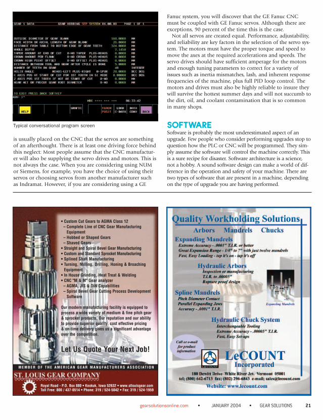
Typical conversational program screen
• Custom Cut Gears to AGMA Class 12– Complete Line of CNC Gear Manufacturing
Equipment– Hobbed or Shaped Gears– Shaved Gears
• Straight and Spiral Bevel Gear Manufacturing• Custom and Standard Sprocket Manufacturing• Splined Shaft Manufacturing• Turning, Milling, Drilling, Honing & Broaching
Equipment• In House Grinding, Heat Treat & Welding• CNC "M & M" Gear analyzer
– AGMA, JIS & DIN Capabilities– Spiral Bevel Gear Cutting Process Development
Software
Our modern manufacturing facility is equipped toprocess a wide variety of medium & fine pitch gear& sprocket products. Our reputation and our abilityto provide superior quality, cost effective pricing & on-time delivery gives us a significant advantageover the competition.
Let Us Quote Your Next Job!
Royal Road - P.O. Box 880 • Keokuk, Iowa 52632 • www.stlouisgear.comToll Free: 800 / 437-0514 • Phone: 319 / 524-5042 • Fax: 319 / 524-1959
M E M B E R O F T H E A M E R I C A N G E A R M A N U FA C T U R E R S A S S O C I AT I O N
PLC SOFTWAREThe PLC software is used to control the machine functions:things like actuators that go in and out, turning pumps onand off, monitoring fault and safety conditions, interlockingfunctions, mode selections, etc. It takes years of experience torefine the design methodologies required to produce a robustPLC program. You simply cannot produce a robust PLC pro-gram in a few days. When you couple the years of experiencerequired with the fact that every manufacturer’s PLC has aslightly different syntax, addressing scheme, and operationalarchitecture, it becomes apparent that you need a highlyskilled engineer to write the PLC program, and a database ofwell-written programs to use as templates.
One example of a robust PLC design is one that I call“event-driven fault and diagnostics.” In this scheme the PLClogic is written to detect and catch every fault or warning.When a fault or warning occurs, the fault is used to display amessage, and to stop the machine if required. Using thisscheme, you can never have a fault that stops the machinewithout a message indicating why the machine has stopped.Another example of a good programming technique is called“operator prompting.” If you have ever operated a machineand pressed a button, only to wonder why that button doesnot function, you know what I mean by operator prompting.Today’s modern PLCs are so powerful that there is no reasonwhy you cannot develop logic that informs the operator whyhe can or cannot press that button.
Development of these types of programming techniquesrequires a good deal of time. A vendor cannot afford to devel-op this type of program for every machine they upgrade,unless they routinely reuse code sections. Suppliers that aresole proprietorships, or that have few engineering talents,probably do not utilize these advanced techniques because ofthe time investment.
CNC SOFTWAREThis type of software can be further broken down into twomain parts. The first part is how the operator enters the pro-gram data, and the second is the method used to turn theprogram data into the proper motions on the machine.Historically speaking, gear machinery software has beendeveloped using what is called a “conversational” approach.In this type of design the operator enters the program data byanswering a series of preprogrammed questions about hispart, tool, and process. An intelligent macro program actuallymoves the axes in the proper sequence to machine the gear.This conversational technique is alive and well in today’smodern gear machinery.
Consider for a moment the task of a rebuilder who isrebuilding a gear-shaping machine and will be applying anew CNC control as part of the process. To satisfy thedemands of their customer, the rebuilder must supply a con-versational program for this machine. The conversationalsoftware development time for such a machine can be meas-
22 GEAR SOLUTIONS • JANUARY 2004 • gearsolutionsonline.com
THE GEAR PEOPLE™
362 Browns Hill Road / P.O. Box 268Locust, NC 28097
Contact us to discuss your custom gear drive needs today!Phone: 800 273 6814Fax: 704 888 4554Email: [email protected]: www.cmgear.com/gearboxes
We have all heard the the old adage “You can’t judge a book by it’scover”. The same can be said for gear boxes. It’s what is on theinside that counts.
Carnes-Miller Gear has been providingopen gearing solutions for over 30 yearsand our reputation for precision, accuracy,and top of the line quality is unquestioned.
NOW! Carnes-Miller Gear can consult,design and manufacture complete customgear boxes for low-to-medium production requirements. If yourbest solution is a custom gear box, why rely on a modified off-the-shelf solution? You can trust a CM Gearbox “inside and out”!
Carnes-Miller Gear Launches a NEW Division - CM Gearbox!
ured in months, if not years. If the rebuilder doesn’t alreadyhave software developed, they have a huge time and costproblem to overcome. Not to mention that you cannot devel-op such a program the first time and have it be fully testedand thorough enough to handle all the requirements on aparticular machine. Developments of these types of conversa-tional programs are evolutions, not revolutions. Be sure thatany vendor you select is up to the task.
DOCUMENTATIONThe final part of the rebuild process involves documentation.If you get a good rebuild done but end up with little or nosupporting documentation, you will have future difficultiesservicing the machine. At a minimum you should receive thefollowing documentation.
• CNC and machine operation manual• CNC programming manual• OEM programming manual (conversational manual)• Electrical schematics• Mechanical drawings for assemblies and parts• Lubrication drawings• Hydraulic system drawings• Coolant system drawings• Software printouts of the PLC and CNC programs• Parameter printouts• CNC system option settings and firmware versions
• All the original machine mechanical drawings and parts books
• The CNC or PLC manuals• The servo system manuals• Complete software backup on CD-ROM or diskette• All purchased component manuals and documentation
Although this article contains a variety of interesting topicson rebuilding a machine, there is simply not enough space tocover all the details that should go into a quality rebuild.Keep in mind when considering a rebuild that not allmachinery rebuilders are created equal. Do not look solely atthe price aspect of the rebuild, look very closely at the details,and ask a lot of questions. Hopefully the information con-tained here will be beneficial to you when investigatingrebuilt machinery in the future.
For more information, visit the Machine Tool Builders Website at [www.machinetoolbuilders.com].
gearsolutionsonline.com • JANUARY 2004 • GEAR SOLUTIONS 23
About the author: Kenneth Flowers is president of Machine Tool Builders: (815) 636-7502, or [email protected]
PARKER HAS THEM ALL
1650 Sycamore Avenue, Bohemia, NY 117161-631-567-1000 • Fax: 1-631-567-1355
Visit us on the Web at: www.parkerind.com or E-Mail: [email protected]
INDUSTRIES INC.
YOUR SINGLE SOURCE FOR GEAR CUTTING TOOLS AND GAGES
Skiving Hobs
Carbide Hobs
Shaper Cutters Master Gears
3 times the average life of other hobs.
Spur or Helical. Spur and Helical.
High quality–class A & AA skivinghobs–fine, medium or coarse pitches.Solid carbide up to approximately 8
DP & carbide tipped for coarserpitches–even larger than 1 DP.
Related Documents