Welcome message from author
This document is posted to help you gain knowledge. Please leave a comment to let me know what you think about it! Share it to your friends and learn new things together.
Transcript


\ ^\
THE
AMERICAN HOUSE-CARPENTER:
A TREATISE UPON
ARCHITECTURE, 3Z
CORNICES AND MOULDINGS,
FRAMINO,
DOORS, WINDOWS, AND STAIRS.
TOGETHER WITH
THE MOST IMPORTANT PRINCIPLES
PRACTICAL GEOMETRY.
^.BY K G. HATFIELD,
ARCHITECT.
Sllustvafea lis more Qan tf)rcc fjuntrrttt 2Snsrab(ns»,
NEW-YORK & LONDON
:
WILEY AND PUTNAM.
1844.
^^^- t^Z ^ ^6 j^^^^r ^fu^c^^.f^^'^-o e-^^-^^^
,<Y^tiffei
Entered according to the Act of Congress, in the year 1844,
BY K. G. HATFIELD,
In the Clerk's office of the District Court of the Southern District of New-York.
NEW-YORK E
WILLIAM OSBORN, PRINTER,88 WiLLIAM-STBRBT,
PREFACE.
This book is intended for carpenters—for masters,
journeymen and apprentices. It has long been the
complaint of this class that architectural books, in-
tended for their instruction, are of a price so high as
to be placed beyond their reach. This is owing, in a
great measure, to the costliness of the plates with
which they are illustrated : an unnecessary expense, as
illustrations upon wood, printed on good paper, answer
every useful purpose. Wood engravings, too, can be
distributed among the letter-press ; an advantage
which plates but partially possess, and one of great
importance to the reader^
Considerations of this kind induced the author to
undertake the preparation of this volume. The sub-
ject matter has been gleaned from works of the first
€iuthority, and subjected to the most careful examina-
tion. The explanations have all been written out
from the figures themselves, and not taken from any
other work ; and the figures have all been drawn ex-
pressly for this book. In doing this, the utmost care
has been taken to make every thing as plain as the
laalure of the case would admits
IV PREFACE.
The attention of the reader is particularly directed to
the following new inventions, viz : an easy method of
describing the curves of mouldings through three
given points ; a rule to determine the projection of
eave cornices ; a new method of proportioning a cor-
nice to a larger given one ; a way to determine the
lengths and bevils of rafters for hip-roofs-; a way to
proportion the rise to the tread in stairs ; to determine
the true position of butt-joints in hand-rails ; to find
the bevils for splayed-work ; a general rule for scrolls,
&:.c. Many problems in geometry^ also, have been
simplified, and new ones introduced. Much labour
has been bestowed upon the section on stairs, in which
the subject of hand-railing is presented, in many re-
spects, in a new, and, it is hoped, more practical form
than in previous treatises on that subject.
The author has endeavoured to present a fund of
useful information to the American house-carpenter
that would enable him to excel in his vocation ; how
far he has been successful in that object, the book
itself must determine.
TABLE OF CONTENTS.
INTRODUCTION.
Art.
Articles necessary for drawing, 2
To prepare the paper, - 5
To use the set-square,
Directions for drawing,
AH.11
13
SECT. I.—PRACTICAL GEOMETRY.
DEFINITIONS.
Lines, - . . .
Angles, - - -
Angular point, -
Polygons, - - -
The circle,
The cone.
Conic sections, - - -
The ellipsis, ...The cylinder,
PROBLEMS.
To bisect a line.
To erect a perpendicular, -
To let fall a perpendicular,
To erect ditto on end of line,
Six, eight and ten rule, -
To square end of board.
To square foundations, dsc.
To let fall a perpendicular
near the end of a line,
To make equal angles, -
To bisect an angle, -
To trisect a right angle,
To draw parallel lines, -
To divide a line into equal
parts, . . . -
To find the centre of a circle,
To draw tangent to circle.
Do. without using centre.
To find the point of contact,
To draw a circle through three
given points,
17
232728
4750
5861
71
727374747474
7576
77
7879
8081
8283
84
85
To find a fourth point in circle, 86To describe a segment of a
circle by a set-triangle, . 87Do. by intersection of lines, 88To curve an angle, - 89To inscribe a circle within a
given triangle, . . 90To make triangle about circle, 91To find the length of a cir-
cumference, - . 92To describe a triangle, hexa-
gon, &c., ... 93To draw an octagon, . 94To eight-square a rail, &c., 94To describe any polygon in
a circle, ... 95To draw equilateral triangle, 96To draw a square by com-
passes, . - . 97To draw any polygon on a
given line, ... 98To form a triangle of required
size, . . - . 99To copy any right-lined figure, 100To make a parallelogram
equal to a triangle, - 101To find the area of a triangle, 101
To make one parallelogram
equal another, - - 102To make one square equal to
two others, - - - 103To find the length of a rafter, 103

VI CONTENTS.
Art.
To find the length of a brace, 103To ascertain the pitch of a
roof, - - - - 103
To ascertain the rake of a
step-ladder, - - - 103
To describe one circle equal
to two others, - - 104
To make one polygon equal
to two or more, - - 104
To make a square equal to
a rectangle, - - 105
To make a square equal to
a triangle, - - - 106
To find a third proportional, 107
To find a fourth proportional, 108
To proportion one ellipsis to
another, - - - 108
To divide a line as another, 109
To find a mean proportional, 110
Definitions of conic sections. 111
To find the axes of an ellipti-
cal section, - - - 112
To find the axes and base of
the parabola, - - 113
To find the height, base andaxes of the hyperbola, - 114
To find foci of ellipsis, - 115
To describe an ellipsis with
a string, - - - 115
To describe an ellipsis with
a trammel, - - 116To construct a trammel, - 116
To describe an ellipsis by or-
dinatQs, - - - 117
To trace a curve through
given points, - - - 117To describe an ellipsis by in-
tersection of lines, - 118
Arl.
Do. from conjugate diameters, 118Do. by intersecting arcs, - 119To describe an oval by com-
passes, - - - 120Do. in the proportion, 7x9,5x7, &c., - - - 121
To draw a tangent to an el-
lipsis, - - - 122To find the point of contact, 123To find a conjugate to the
given diameter, - 124To find the axes from given
diameters, - - - 125To find axes proportionate to
given ones, - - 126To describe a parabola by in-
tersection of lines, - - 127To describe hyperbola by do., 128
DEMONSTRATIONS
.
Definitions, axioms, &c., 130. 139Addition of angles, - 140Equal triangles, • - - 141Angles at base of isoceles tri-
angle equal, - - 142Parallelograms divided equal-
ly by diagonal, - - 143Equal parallelograms, - 144Parallelogram equal triangles, 146To make triangle equal poly-
gon, - - . . 147Opposite angles equal, - 148Angles of triangle equal two.
right angles, - - - 149Corollaries from do., 150. 155Angle in semi-circle a right
angle, - - - 156Hecatomb problem, - - 157
SECT. II.—ARCHITECTURE.
HISTOKY,
Antiquity of its origin.
Its cultivation among the an-
cients, ...Among the Greeks, -
1.59
160
Among the Romans,Ruin caused by Goths
Vandals,
Of the Gothic,
and
161 Of the Lombard,
162
163164165

CONTENTS. Vll
Art.
Ofthe Byzantine and Oriental, 166
Moorish, Arabian and ModernGothic, - - - 167
Of the English, - - 168
Revival of the art in the sixth
century, - - - 169
The art improved in the 14th
and 15th centuries, - 170
Roman styles cultivated, 171
STYLES.
Origin of different styles, 172
Stylobate and pedestal, - 173
Definitions of an order, - 174
Of the several parts of an
order, - - 175. 185
Art.
Extent of Roman structures, 202Roman styles copied from
Grecian, - - - 203Origin of the Tuscan, - 204Adaptation, - - - 205Characteristics of the Egypt-
ian, - . - - 206Extent of Egyptian structures, 206Adaptation, - - - 207Appropriateness ofdesign, 208. 211Durable structures, - - 212Plans of dwellings, &c., 213Directions for designing, 213, 214
PRINCIPLES.
To proportion an order. 186 Origin of the art, 215The Grecian orders. 187 Arrangement and design, - 21ff
Origin of the Doric, - 188 Ventilation and cleanliness. 2irIntercolumniation, - 189 Stability, 218Adaptation, 190 Ornaments, - - - 219Origin of the Ionic, 191 Scientific knowledge neces-
Characteristics, 192 sary. 220Intercolumniation, - 193 The foundation. 221Adaptation, 194 The column, - - - 222To describe the volute, - 195 The wall, 22aOrigin of the Corinthian, 196 The lintel, - 224Adaptation, - 197 The arch, 225Persians, . . - - 199 The vault,' - 226.
Caryatides, 200 The dome, ... 227The Roman orders, - 202 The roof, 22&-
SECT. III.—MOULDINGS, CORNICES, &c.
MOULDINGS, &C.Elementary forms, - - 229Characteristics, - - 230Grecian and Roman, - - 231Profile, - - - 232To describe the torus and
scotia, - - - - 233To describe the echinus, 234To describe the cavetto, 235To describe the cyma-recta, 236To describe the cyma-reversa, 237
Roman mouldings^ - 238'
Modern mouldings, - - 239'
Antse caps, - - - 240CORNICES;
Designs, - - - - 241To proportion an eave cornice, 242
Do. from a smaller given
one, - - . - 243Do. from a larger given
one, . - . - 244Tofind shape of angle-bracket, 245To find form of raking cornice, 246
VIU CONTENTS.
SECT. IV.—FRAMING.
Art.
Laws of pressure, - - 248Parallelogram of forces, - 248
To measure the pressure on
rafters, - - - 249
Do. on tie-beams, - 250
The effect of position, - 251
The composition of forces, 252
Best position for a strut, - 253
Nature of ties and struts, - 254
To distinguish ties from struts, 255Lattice-work framing, - 256Direction of pressure in raft-
ers, - - - - 257Oblique thrust of lean-to roofs, 258Pressure on floor-beams, - 259
Kinds of pressure, - - 260
Resistance to compression, 261
Area of post, - - 261
Resistance to tension, - 262Area of suspending piece, 262
Resistance to cross-strains, 263Area of bearing timbers, 263Area of stiffest beam, - 264Bearers narrow and deep, 265Principles of framing, - 266
FLOORS.
Single-joisted, - - 267To find area of floor-timbers, 268Dimensions of trimmers, &c., 269Strutting between beams, 270Cross-furring and deafening, 271Double floors, - - - 272Dimensions of binding-joists, 273
Do. of bridging-joists, 274Do. of ceiling-joists, - 275
Framed floors, - . - 276Dimensions of girders, - 277Girders sawn and bolted, - 278Trussed girders, - - 279Floors in general, - - 280
PARTITIONS.
Nature of their construction, 281Designs for partitions, - 282Superfluous timber, - - 282Improved method, - - 283Weight of partitioning, - 284
ROOFS.
Lateral strains.
Pressure on roofs,
Weight of covering,
Definitions,
Relative size of timbers,
Art.
285286286287288
To find the area of a king-post, 289Of a queen-post, - - 290Of a tie-beam, . - - 291Of a rafter, - - - 292Of a straining-beam, - 294Of braces, - - - 295Of purlins, - - - 296Of common rafters, - 297To avoid shrinkage,- - - 298Roof with a built-rib, - 299Badly-constructed roofs, - 300To find the length and bevils
in hip-roofs, - - 301To find the backing of a hip-
rafter, ... - 302DOMES.
With horizontal ties, - 303Ribbed dome, - - - 304Area of the ribs, - - 305Curve of equilibrium, - 306To describe a cubic parabola, 307Small domes for stairways, 308To find the curves of the ribs, 309To find the shape of the cover-
ing for spherical domes, 310Do. when laid horizontally, 311
To find an angle-rib, - . 312BRIDGES.
Wooden bridge with tie-beam, 313Do. without a tie-beam, 314Do. with a built-rib, 315
Table of least rise in bridges, 315Rule for built-ribs, - - 315Pressure on arches, - 316To form bent-ribs, - - 317Elasticity of timber, . 317To construct a framed rib, 318Width of roadway, &c., • 319Stone abutments and piers, 320
Piers constructed of piles, 321

CONTENTS. IX.
Art.
Piles in ancient bridges, 321
Centring for stone bridges, 322
Pressure of arch-stones, - 322Centre without a tie at the
base, - - - 323Construction of centres, - 324General directions, - 325Lowering centres, - - 326Relative size of timbers, - 327
Short rule for do. - - 328
Joints between arch-stones, 329Do. in elliptical arch, - 330Do. in parabolic arch, - 331
JOINTS.Art.
Scai'fing, or splicing, 332. 334To proportion the parts, - 335Joints in beams and posts, - 336Joints in floor-timbers, - 337Timber weakened by framing, 338Joints for rafters and braces, 339*
Evil of shrinking avoided, - 340Proper joint for collar-beam, 341Pins, nails, bolts and straps, 342Dimensions of straps, - 342To prevent the rusting of
straps, - - - - 342
SECT, v.—DOORS, WINDOWS, &c.
DOORS.
Dimensions of doors, - - 343To proportion height to width, 344Width of stiles, rails and
panels, - - - 345Example of trimming, - 346
Elevation of a door and trim-
mings.
General directions
ing doors,
347for hanff-
348
WINDOWS.To determine the size, - 349'
To find dimensions of frame, 350To proportion box to flap
shutter, - - - 351To proportion and arrange
windows, - - - 352Circular-headed windows, 353To find the form of the soffit, 354Do. in a circular wall, - 355-
SECT. VI.—STAIRS.
Their position, - - - 356Principles of the pitch-board, 357
To proportion the rise to the
tread, - - - 358The angle of ascent, - - 359Length of steps, - - 360
To construct a pitch-board, 361
To lay-out the string, - 362Section of step, - - 363
PLATFOKM STAIRS.
To construct the cylinder, - 364To cut the lower edge of do., 365
To place the balusters, - 366
To find the moulds for the
rail, . . - . 36TElucidation of this method, 368Two other examples, 369, 37aTo apply the mould to the
plank, - - - 371To bore for the balusters, - 372Face-mould for moulded rail, 373To apply this mould to plank, 374To ascertain thickness of stuff", 375
WINDING STAIRS.
Flyers and winders, - 376To construct winding stairs, 37T
CONTENTS.
Art.
Timbers to support winding
stairs, . - - -
To find falling-mould of rail,
To find face-mould of do..
Position of butt-joint,
To ascertain thickness of
stuff, - - - -
To apply the mould to plank, 383Elucidation of the butt-joint, 384Quarter-circle stairs,
Falling-mould for do..
Face-mould for do.,
Elucidation of this method,
To bevil edge of plank.
To apply moulds without be-
villing plank, - 390
378379380380
381
385386387388389
To find bevils for splayed-
work, - - - 391Another method for face-
moulds, - - - 392To apply face-mould to plank, 394To apply falling-mould, - 395
SCROLLS.
General rule, - - 396To describe scroll for rail, 398For curtail-step, - - 399Balusters under scroll, - 400Falling-mould for scroll, - 401Face-mould for do., - 402Round rails over winders, - 403To find form of newel-cap, 404f
APPEND IX.
Page.
Glossary of Architectural Terms, - . . - zTable of Squares, Cubes and Roots, - - - - 14Rules for extending the use of the foregoing table, - - 21Rule for finding the roots of whole numbers with decimals, - 23Rules for the reduction of Decimals, - - - 23Table of Areas and Circumferences of Circles, ... 25Rules for extending the use of the foregoing table, - - 28Table showing the Capacity of Wells, Cisterns, &c., - - 29Rules for finding the Areas, &c., of Polygons, . - 30Table of Weights of Materials, - - - - - 31
INTRODUCTION.
Art. 1.—A knowledge of the properties and principles of lines
can best be acquired by practice. Although the various problems
throughout this work may be understood by inspection, yet they
will be impressed upon the mind with much greater force, if they
are actually performed with pencil and paper by the student.
Science is acquired by study—art by practice : he, therefore, who
would have any thing more than a theoretical, (which must of
necessity be a superficial,) knowledge of Carpentry, will attend
to the following directions, provide himself with the articles here
specified, and perform all the operations described in the follow-
ing pages. Many of the problems may appear, at the first read-
ing, somewhat confused and intricate ; but by making one line
at a time, according to the explanations, the student will not
only succeed in copying the figures correctly, but by ordinary
attention will learn the principles upon which they are based,
and thus be able to make them available in any unexpected case
to which they may apply.
2.—The following articles are necessary for drawing, viz : a
drawing-board, paper, drawing-pins or mouth-glue, a sponge, a
T-square, a set-square, two straight-edges, or flat rulers, a lead
pencil, a piece of india-rubber, a cake of india-ink, a set of draw-
ing-instruments, and a scale of equal parts.
3.—The size of the drawing-hoard must be regulated accord-
ing to the size of the drawings which are to be made upon it.
Yet for ordinary practice, in learning to draw, a board about 15
1
A AMERICAN HOUSE CARPENTER.
by 20 inches, and one inch thick, will be found large enough,
and more convenient than a larger one. This board should be
well-seasoned, perfectly square at the corners, and without
clamps on the ends. A board is better without clamps, because
the little service they are supposed to render by preventing the
board from warping, is overbalanced by the consideration that
the shrinking of the panel leaves the ends of the clamps project-
ing beyond the edge of the board, and thus interfering with the
proper working of the stock of the T-square. "When the stuff
is well-seasoned, the warping of the board will be but trifling;
and by exposing the rounding side to the fire^ or to the sun, it
may be brought back to its proper shape.
4.—For mere line drawings, the paper need not commonly
be what is called drawing-paper ; as this is rather costly, and
will, where much is used, make quite an item of expense.
Cartridge-paper, as it is called, of about 20 by 26 inches, and of
as good a quality nearly as drawing-paper, can be bought for
about 50 cts. a quire, or 2 pence a sheet ; and each sheet may be
cut in halves, or even quarters, for practising. If the drawing
is to be much used, as working drawings generally are, cartridge-
paper is much better than the other kind.
5.—A drawing-pin is a small brass button, having a steel pin
projecting from the under side. By having one of these at each
corner, the paper can be fixed to the board ;but this can be done
in a much better manner with mouth-glue. The pins will pre-
vent the paper from changing its position on the board ; but,
more than this, the glue keeps the paper perfectly tight and
smooth, thus making it so much the more pleasant to work on.
To attach the paper with mouth-glue, lay it with the bottom
side up, on the board ; and with a straight-edge and penknife,
cut off the rough and uneven edge. With a sponge moderately
wet, rub all the surface of the paper, except a strip around the
edge about half an inch wide. As soon as the glistening of the
water disappears, turn the sheet over^ and place it upon the
INTRODUCTION. 3
board just where you wish it ghied. Commence upon one of
the longest sides, and proceed thus : lay a flat ruler upon the
paper, parallel to the edge, and within a quarter of an inch of it.
With a knife, or any thing similar, turn up the edge of the paper
against the edge of the ruler, and put one end of the cake of
mouth-glue between your lips to dampen it. Then holding it
upright, rub it against and along the entire edge of the paper
that is turned up against the ruler, bearing moderately against
the edge of the ruler, which must be held firmly with the left
hand. Moisten the glue as often as it becomes dry, until a
sufiiciency of it is rubbed on the edge of the paper. Take
away the ruler, restore the turned-up edge to the level of the
board, and lay upon it a strip of pretty stiiF paper. By rubbing
upon this, not very hard but pretty rapidly, with the thumb nail
of the right hand, so as to cause a gentle friction, and heat to be
imparted to the glue that is on the edge of the paper, you will
make it adhere to the board. The other edges in succession
must be treated in the same manner.
Some short distances along one or more of the edges, may
afterwards be found loose : if so, the glue must again be applied,
and the paper rubbed until it adheres. The board must then be
laid away in a warm or dry place ; and in a short time, the sur-
face of the paper will be drawn out, perfectly tight and smooth,
and ready for use. The paper dries best when the board is laid
level. When the drawing is finished, lay a straight-edge upon
the paper, and cut it from the board, leaving the glued strip still
attached. This may afterwards be taken off" by wetting it freely
with the sponge ; which will soak the glue, and loosen the
paper. Do this as soon as the drawing is taken off, in order that
the board may be dry when it is wanted for use again. Care
must be taken that, in applying the glue, the edge of the paper
does not become damper than the rest : if it should, the paper
must be laid aside to dry, (to use at another time,) and another
sheet be used in its place.
4 AMERICAN HOUSE CARPENTER.
Sometimes, especially when the drawing board is new, the
paper will not stick very readily ; but by persevering, this diffi-
culty may be overcome. In the place of the mouth-glue, a
strong solution of gum-arabic may be used, and on some
accounts is to be preferred ; for the edges of the paper need not
be kept dry, and it adheres more readily. Dissolve the gum in
a sufficiency of warm water to make it of the consistency of
linseed oil. It must be applied to the paper with a brush, when
the edge is turned up against the ruler, as was described for the
mouth-glue. If two drawing-boards are used, one may be in use
while the other is laid away to dry ; and as they may be cheaply
made, it is advisable to have two. The drawing-board having
a frame around it, commonly called a panel-board, may affijrd
rather more facility in attaching the paper when this is of the
size to suit;yet it has objections which overbalance that con-
sideration.
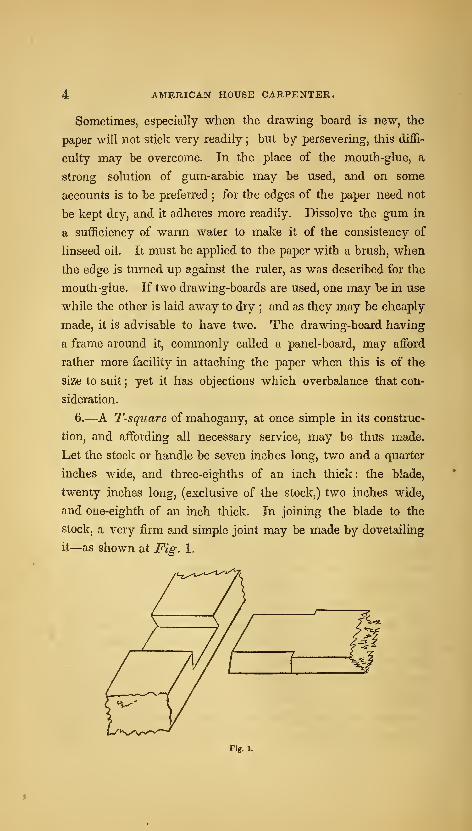
6.—A T-square of mahogany, at once simple in its construc-
tion, and affording all necessary service, may be thus made.
Let the stock or handle be seven inches long, two and a quarter
inches wide, and three-eighths of an inch thick: the blade,
twenty inches long, (exclusive of the stock,) two inches wide,
and one-eighth of an inch thick. In joining the blade to the
stock, a very firm and simple joint may be made by dovetailing
it—as shown at Fig. 1.
Fig. 1.

INTRODUCTION. »
7.—The set-square is in the form of a right-angled triangle;
and is commonly made of mahogany, one-eighth of an inch in
thickness. The size that is most convenient for general use, is
six inches and three inches respectively for the sides which con-
tain the right angle ; although a particular length for the sides is
by no means necessary. Care should be taken to have the square
corner exactly true. This, as also the T-square and rulers,
should have a hole bored through them, by which to hang them
upon a nail when not in use.
8.—One of the rulers may be about twenty inches long, and
the other six inches. The pencil ought to be hard enough to
retain a fine point, and yet not so hard as to leave inefiaceable
marks. It should be used lightly, so that the extra marks that
are not needed when the drawing is inked, may be easily rubbed
off with the rubber. The best kind of india-ink is that which
will easily rub off upon the plate ; and, when the cake is rub-
bed against the teeth, will be free from grit.
9.—The drawing-instruments may be purchased of mathe-
matical instrument makers at various prices : from one to one
hundred dollars a set. In choosing a set, remember that the
lowest price articles are not always the cheapest. A set, com-
prising a sufficient number of instruments for ordinary use, well
made and fitted in a mahogany box, may be purchased at Pike
and Son's, (Broadway, near Maiden-lane, N. Y.,) for three or four
dollars. The compasses in this set have a needle point, which
is much preferable to a common point.
10.—The best scale of equal parts for carpenters' use, is one
that has one-eighth, three-sixteenths, one-fourth, three-eighths,
one-half, five-eighths, three-fourths, and seven-eighths of an
inch, and one inch, severally divided into tivelfths, instead of
being divided, as they usually are, into tenths. By this, if it be
required to proportion a drawing so that every foot of the object
represented will upon the paper measure one-fourth of an inch,
use that part of the scale which is divided into one-fourths ofan

6 AMERICAN ilOUSE-CARPENTER.
inch, taking for every foot one of those divisions, and for every
inch one of the subdivisions into twelfths; and proceed in like
manner in proportioning a drawing to any of the other divisions
of the scale. An instrument in the form of a semi-circle, called a
protractor, and used for laying down and measuring angles, is
of much service to surveyors, but not much to carpenters.
11.—In drawing parallel lines, when they are to be parallel
to either side of the board, use the T-square ; but when it is
required to draw lines parallel to a line which is drawn in a
direction oblique to either side of the board, the set-square must
be used. Let a b, {Fig. 2,) be a line, parallel to which it is
Fig-. 2.
desired to draw one or more lines. Place any edge, as c d, of
the set-square even with said line ; then place the ruler, g h,
against one of the other sides, as c e, and hold it firmly ; slide
the set-square along the edge of the ruler as far as it is desired,
as at/; and a line drawn by the edge, if, will be parallel to a h.
12.—To draw a line, as k I, {Fig. 3,) perpendicular to another,
as a 6, set the shortest edge of the set-square at the line, a b;
place the ruler against the longest side, (the hypothenuse of the
right-angled triangle ;) hold the ruler firmly, and slide the set-
square along until the side, e d, touches the point, k ; then the
line, I k, drawn by it, will be perpendicular to a b. In like
INTRODUCTION.
manner, the drawing of other problems may be facilitated, as will
be discovered in using the instruments.
Fig. 3.
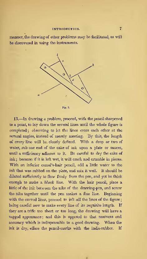
13.—In drawing a problem, proceed, with the pencil sharpened
to a point, to lay down the several lines until the whole figure is
completed ; observing to let the lines cross each other at the
several angles, instead of merely meeting. By this, the length
of every line will be , clearly defined. With a drop or two of
water, rub one end of the cake of ink upon a plate or saucer,
until a sufficiency adheres to it. Be careful to dry the cake of
ink ; because if it is left wet, it will crack and crumble in pieces.
With an inferior camel's-hair pencil, add a little water to the
ink that was rubbed on the plate, and mix it well. It should be
diluted sufficiently to flow freely from the pen, and yet be thick
enough to make a Mack line. With the hair pencil, place a
little of the ink between the nibs of the drawing-pen, and screw
the nibs together until the pen makes a fine line. Beginning
with the curved lines, proceed to ink all the lines of the figure
;
being careful now to make every line of its requisite length. If
they are a trifle too short or too long, the drawing will have a
ragged appearance ; and this is opposed to that neatness and
accuracy which is indispensable to a good drawing. When the
ink is dry, eiface the pencil-marks with the india-rubber. If

8 AMERICAN HOUSE-CARPENTER.
the pencil is used lightly, they will all rub oiF, leaving those
lines only that were inked.
14.
—
In problems, all auxiliary lines are drawn light ; while
the lines given and those sought, in order to be distinguished at
a glance, are made much heavier. The heavy lines are made
so, by passing over them a second time, having the nibs of the
pen separated far enough to make the lines as heavy as desired.
If the heavy lines are made before the drawing is cleaned with
the rubber, they will not appear so black and neat ; because the
india-rubber takes away part of the ink. If the drawing is a
ground-plan or elevation of a house, the shade-lines, as they are
termed, should not be put in until the drawing is shaded ; as
there is danger of the heavy lines spreading, when the brush, in
shading or coloring, passes over them. If the lines are inked
with common writing-ink^ they will, however fine they may be
made, be subject to the same evil ; for which reason, india-ink
is the only kind to be used.

THE
AMERICAN HOUSE-CARPENTER.
SECTION I.—PRACTICAL GEOMETRY.
DEFINITIONS.
15.— Geometry treats of the properties of magnitudes.
16.
—
A point has neither length, breadth, nor thickness.
17.—A line has length only.
18.
—
Superficies has length and breadth only.
19.—A plane is a surface, perfectly straight and even in every
direction ; as the face of a panel "when not warped nor winding.
20.—A solid has length, breadth and thickness.
21.—A right, or straight, line is the shortest that can be
drawn between two points.
22.
—
Parallel lines are equi-distant throughout their length.
23.—An angle is the inclination of two lines towards one
another. {Fig. 4.)
Fig. 4. Fig. 5. Fig. 6.
2
10 AMERICAN HOUSE-CARPENTER.
24.—A right angle has one line perpendicular to the other.
{Fig. 5.)
25.—An oblique angle is either greater or less than a right
angle. [Fig. 4 and 6.)
26.—An acute angle is less than a right angle. [Fig. 4.)
27.—An obtuse angle is greater than a right angle. [Fig. 6.)
When an angle is denoted by three letters, the middle one, in
the order they stand, denotes the angular point, and the other
two the sides containing the angle ; thus, let ab c, {Fig. 4,) bethe angle, then b will be the angular point, and a b and b c will
be the two sides containing that angle.
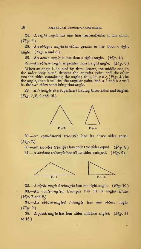
28.—A triangle is a superficies having three sides and angles.
{Fig. 7, 8, 9 and 10.)
Fig. 7. Fig. 8.
29.—An equi-lateral triangle has its three sides equal.
{Fig. 7.)
30.—^An isoceles triangle has only two sides equal. {Fig. 8.)
31.—A scalene triangle has all its sides unequal. {Fig. 9)
Fig. 10.
32.—A right-angled triangle has one right angle. {Fig. 10.)
33.—^An acute-angled triangle has all its angles acute.
{Fig. 7 and 8.)
34.—An obtuse-angled triangle has one obtuse angle.
{Fig. 9.)
35.—A quadrangle has four sides and four angles. {Fig. 11
ta 16»)

PRACTICAL GEOMETRY. 11
Fig. 11. Fig. 12.
36.—A parallelogram is a quadrangle having its opposite
sides parallel. {Fig. 11 to 14.)
37.—A rectangle is a parallelogram, its angles being right
angles. {Fig. 11 and 12.)
38.—A square is a rectangle having equal sides. {Fig. 11.)
39.—A rhombus is an equi-lateral parallelogram having ob-
lique angles. {Fig. 13.)
Fig. 13. Fig. 14.
40.—A rhomboid is a parallelogram having oblique angles.
{Fig. 14.)
41.—A trapezoid is a quadrangle having only two of its sides
parallel. {Fig. 15.)
Fig. 15. Fig. 16.
42.—A trapezium is a quadrangle which has no two of its
sides parallel. {Fig. 16.)
43.—A polygon is a figure bounded by right lines.
44.—A regular polygon has its sides and angles equal.
45.—An irregular polygon has its sides and angles unequal.
46.—A trigon is a polygon of three sides, {Fig. 7 to 10 ;)
^tetragon has four sides, {Fig. 11 to 16;) a pentagon has
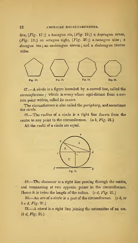
12 AMERICAN HOUSE-CARPENTER.
five, [Fig. 17 ;) a hexagon six, {Fig. 18 ;) a heptagon seven,
(Fi^. 19 ;) an octagon eight, (F^^. 20 ;) a nonagon nine ; a
decagon ten ; an undecagon eleven;and a dodecagon twelve
sides.
Fig. 17. Fig. 18. Fig. 19. Fig. 20.
47.—A circle is a figure bounded by a curved line, called the
circumference ; which is every where equi-distant from a cer-
tain point within, called its centre.
The circumference is also called the periphery^ and sometimesthe circle.
48.—The radius of a circle is a right line drawn from the
centre to any point in the circumference, (a 6, Fig. 21.)
All the radii of a circle are equal.
Fig. 21.
49.—The diameter is a right line passing through the centre,
and terminating at two opposite points in the circumference.
Hence it is twice the length of the radius, (c d, Fig. 21.)
50.—An arc of a circle is a part of the circumference, (c 6, or
hed, Fig. 21.)
51.—A chord is a right line joining the extremities of an arc.
(6 d, Fig. 21.)
PRACTICAL GEOMETRY. 13
52.—A segment is any part of a circle bounded by an arc and
its chord. [A, Fig. 21.)
53.—A sector is any part of a circle bounded by an arc and
two radii, drawn to its extremities. {B^ Fig. 21.)
54.—A quadrant^ or quarter of a circle, is a sector having a
quarter of the circumference for its arc. (C, Fig. 21.)
55.—A tangent is a right line, which in passing a curve,
touches, without cutting it. {f g^ Fig. 21.)
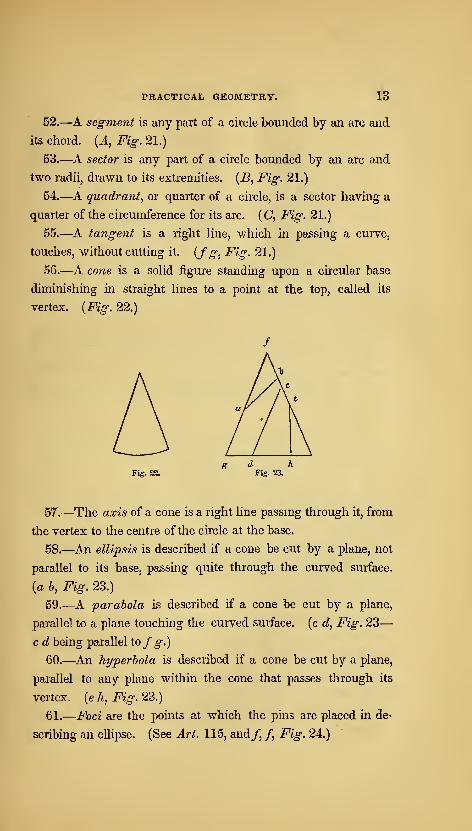
56.—A cone is a solid figure standing upon a circular base
diminishing in straight lines to a point at the top, called its
vertex. {Fig. 22.)
Fig. 22. Fig. 23.
57.—The axis of a cone is a right line passmg through it, from
the vertex to the centre of the circle at the base.
58.—An ellipsis is described if a cone be cut by a plane, not
parallel to its base, passing quite through the curved surface,
(a 6, Fig. 23.)
59.—A parabola is described if a cone be cut by a plane,
parallel to a plane touching the curved surface, (c d, Fig. 23
—
c d being parallel tofg.)
60.—An hyperbola is described if a cone be cut by a plane,
parallel to any plane within the cone that passes through its
vertex, (e h, Fig. 23.)
61.
—
Foci are the points at which the pins are placed in de-
scribing an ellipse. (See Art. 115, and/, /, Fig. 24.)
14 AMERICAN HOUSE-CARPENTER.
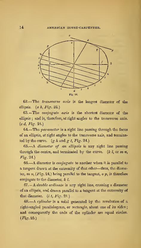
62.—The transverse axis is the longest diameter of the
ellipsis, {a b, Fig. 24.)
63.—The conjugate axis is the shortest diameter of the
ellipsis ; and is, therefore, at right angles to the transverse axis,
(c d, Fig. 24.)
64.—The parameter is a right line passing through the focus
of an ellipsis, at right angles to the transverse axis, and termina-
ted by the curve, {g h and g t, Fig. 24.)
65.—A diameter of an ellipsis is any right line passing
through the centre, and terminated by the curve, [k Z, or m, n,
Fig. 24.)
66.—A diameter is conjugate to another when it is parallel to
a tangent drawn at the extremity of that other—thus, the diame-
ter, m n, {Fig. 24,) being parallel to the tangent, o p, is therefore
conjugate to the diameter, k I.
67.—A double ordinate is any right line, crossing a diameter
of an ellipsis, and drawn parallel to a tangent at the extremity of
that diameter, {i t, Fig. 24.)
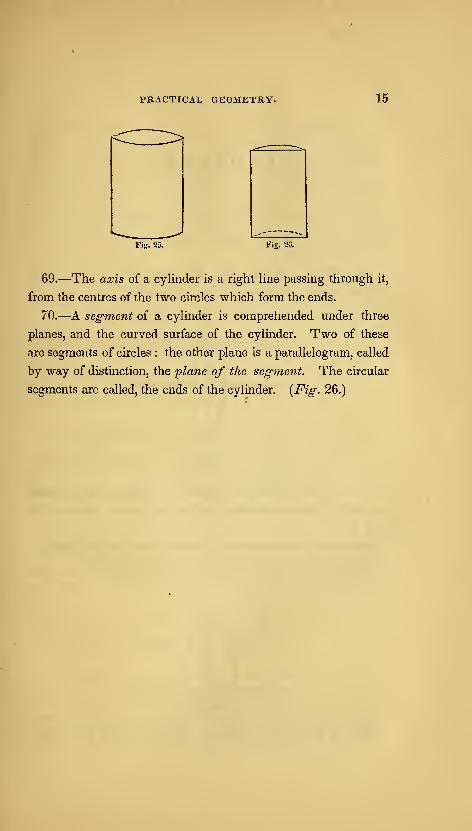
68.—A ci/linder is a solid generated by the revolution of a
right-angled parallelogram, or rectangle, about one of its sides;
and consequently the ends of the cylinder are equal circles.
{Fig. 25.)
PRACTICAL GEOMETRY. 15
Fig. 26.
69.—The axis of a cylinder is a right line passing through it,
from the centres of the two circles which form the ends.
70.—A segment of a cylinder is comprehended under three
planes, and the curved surface of the cylinder. Two of these
are segments of circles : the other plane is a parallelogram, called
by way of distinction, the ylane of the segment. The circular
segments are called, the ends of the cylinder. {Fig. 26.)
PROBLEMS.
RIGHT LINES AND ANGLES.
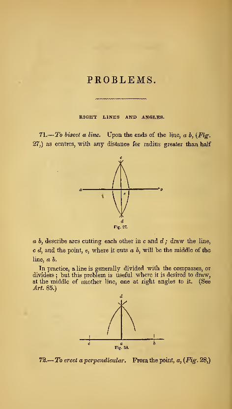
71.— To bisect a line. Upon the ends of the line, a b, [Fig.
27,) as centres, with any distance for radius greater than half
a 6, describe arcs cutting each other in c and d ; draw the line,
c d, and the point, e, where it cuts a b, will be the middle of the
line, a b.
In practice, a line is generally divided with the compasses, or
dividers; but this problem is useful where it is desired to draw,
at the middle of another line, one at right angles to it. (See
Art. 85.)
d
Fig. 28.
72.
—
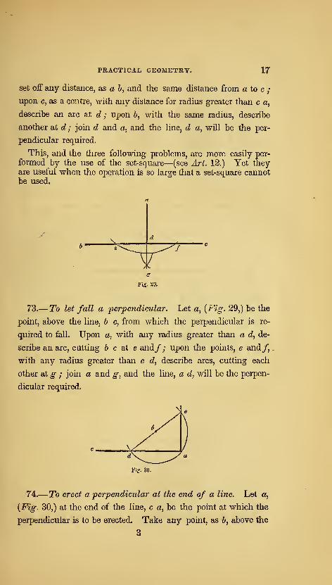
To erect a perpendicular. From the point, a, {Fig. 28,)
PRACTICAL GEOMETRY. 17
set off any distance, as a b, and the same distance from a to c ;
upon c, as a centre, with any distance for radius greater than c a,
describe an arc at d ; upon b, with the same radius, describe
another at d ; join d and a, and the hne, d a, will be the per-
pendicular required.
This, and the three following problems, are more easily per-
formed by the use of the set-square—(see Art. 12.) Yet theyare useful when the operation is so large that a set-square cannotbe used.
^
Fig. 29.
73.— To let fall a perpendicular. Let a, {Fig. 29,) be the
point, above the line, b c, from which the perpendicular is re-
quired to fall. Upon a, with any radius greater than a d, de-
scribe an arc, cutting 6 c at e and/; upon the points, e and/,
with any radius greater than e c?, describe arcs, cutting each
other at g ; join a and g, and the line, a d, will be the perpen-
dicular required.
Fig. 30.
74.
—
To erect a perpendicular at the end of a line. Let a,
{Fig. 30,) at the end of the line, c a, be the point at which the
perpendicular is to be erected. Take any point, as b, above the
3

18 AMERICAN HOUSE-CARPENTER.
line, c a, and with the radius, h a, describe the arc, d a e;
through d and 6, draw the line, d e ; join e and «, then e a will
be the perpendicular required.
The principle here made use of, is a very important one ; andis applied in many other cases—(see Art. 81, 6, and Art. 84.
For proof of its correctness, see Art. 156.)
Fig. 31.
74, a.—A second method. Let 6, {Fig. 31,) at the end of the
line, a b, be the point at which it is required to erect a perpen-
dicular. Upon b, with any radius less than b a, describe the arc,
c e d ; upon c, with the same radius, describe the small arc at e,
and upon e, another at d ; upon e and d, with the same or any
other radius greater than half e d, describe arcs intersecting at/;
join/ and b, and the line,/ 6, will be the perpendicular required.
Fig. 32.
74, b.—A third method. Let b, {Fig. 32,) be the given point
at which it is required to erect a perpendicular. Upon &, with any
radius less than b a, describe the quadrant, d ef; upon d, with
the same radius, describe an arc at e, and upon e, another at c ;

PRACTICAL GEOMETRY. 19
through d and e, draw d «, cutting the arc in c ; join c and 6,
then c h will be the perpendicular required.
This problem can be solved by the six, eight and ten rule,
as it is called ; which is founded upon the same principle as
the problems at Art. 103, 104 ; and is applied as follows. Leta d, {Fig. 30,) equal eight, and a e, six ; then, ii d e equals ten,
the angle, e a d, is b, right angle. Because the square of six
and that of eight, added together, equal the square of ten, thus :
6 X 6 = 36, and 8 X 8 = 64 ; 36 + 64 = 100, and 10 x 10 =100. Any sizes, taken in the same proportion, as six, eight andten, will produce the same effect : as 3, 4 and 5, or 12, 16 and20. (See note to Art. 103.)
By the process shown at Fig. 30, the end of a board may besquared without a carpenters'-square. All that is necessary is a
pair of compasses and a ruler. Let c a be the edge of the board,
and a the point at which it is required to be squared. Take the
point, b, as near as possible at an angle of forty-five degrees, or ona mitre-line, from a, and at about the middle of the board. Thisis not necessary to the working of the problem, nor does it affect
its accuracy, but the result is more easily obtained. Stretch the
compasses from b to a, and then bring the leg at a around to d ;
draw a line from d, through 6, out indefinitely ; take the dis-
tance, d b, and place it from b to e ; join e and a ; then e a will
be at right angles to c a. In squaring the foundation of a build-
ing, or laying-out a garden, a rod and chalk-line may be usedinstead of compasses and ruler.
75.— To let fall a perpendicular near the end of a line.
Let e, {Fig. 30,) be the point above the line, c a, from which the
perpendicular is required to fall. From e, draw any line, as e d,
obliquely to the line, c a ; bisect e d at b ; upon b, with the
radius, b e, describe the arc, e a d ; join e and a ; then e a will
be the perpendicular required.
76.—To make an angle, (as e df Fig. 33,) equal to a given
angle, (as b a c.) From the angular point, a, with any radius,
describe the arc, 6c/ and with the same radius, on the line, d e,
20 AMERICAN HOUSE-CARPENTER.
and from the point, c?, describe the wcc,fg; take the distance,
b c, and upon g, describe the small arc at/; join/ and d ; and
the angle, e df, will be equal to the ahgle, b a c.
If the given line upon which the angle is to be made, is situa-
ted parallel to the similar line of the given angle, this may beperformed more readily with the set-square. (See Art. 11.)
Fig. 34.
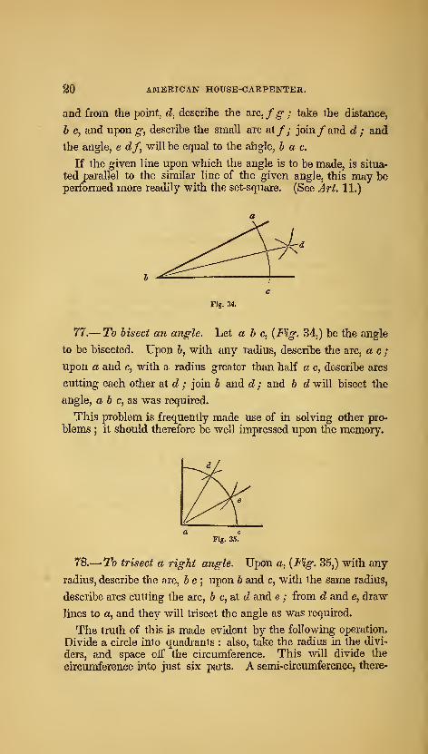
77.—To bisect an angle. Let a b c, {Fig. 34,) be the angle
to be bisected. Upon 6, with any radius, describe the arc, a c;
upon a and c, with a radius greater than half a c, describe arcs
cutting each other at d ; join b and d ; and b d will bisect the
angle, a 6 c, as was required.
This problem is frequently made use of in solving other pro-
blems;
it should therefore be well impressed upon the memory.
Fig. 35.
78.
—
To trisect a right angle. Upon a, {Fig. 35,) with any
radius, describe the arc, b c ; upon b and c, with the same radius,
describe arcs cutting the arc, 6 c, at c? and e ; from d and e, draw
lines to a, and they will trisect the angle as was required.
The truth of this is made evident by the following operation.
Divide a circle into quadrants : also, take the radius in the divi-
ders, and space off the circumference. This will divide the
circumference into just six parts. A semi-circumference, there-
PRACTICAL GEOMETRY. 21
fore, is equal to three, and a quadrant to one and a half of those
parts. The radius, therefore, is equal to f of a quadrant; and
this is equal to a right angle.
Fig. 36.
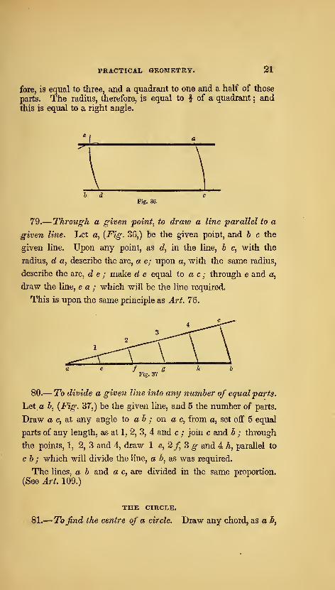
79.— Through a given point, to draw a line parallel to a
given line. Let a, {Fig. 36,) be the given point, and b c the
given line. Upon any point, as d, in the line, b c, with the
radius, d a, describe the arc, a c; upon a, with the same radius,
describe the arc, d e ; make d e equal to a c ; through e and a,
draw the line, e a ; which will be the line required.
This is upon the same principle as Art. 76.
80.— To divide a given line into any number of equal parts.
Let a A, {Fig. 37,) be the given line, and 5 the number of parts.
Draw a c, at any angle Xo ah ; on a c, from a, set off 5 equal
parts of any length, as at 1, 2, 3, 4 and c ; join c and b ; through
the points, 1, 2, 3 and 4, draw 1 e, 2/, 3 ^ and 4 h, parallel to
c b ; which will divide the line, a b, as was required.
The lines, a b and a c, are divided in the same proportion.
(See Art. 109.)
THE CIRCLE.
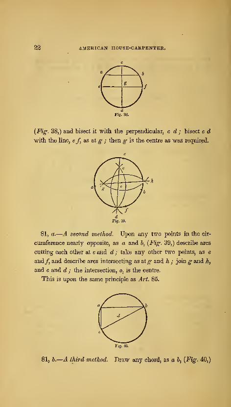
81.— Tofind the centre of a circle. Draw any chord, as a B,
22 AMERICAN HOUSE-CARPENTER.
{Fig. 38,) and bisect it with the perpendicular, c d ; bisect c d
with the Hne, ef, as at g ; then g is the centre as was required.
81, a.—A second method. Upon any two points in the cir-
cumference nearly opposite, as a and b, {Fig. 39,) describe arcs
cutting each other at c and d ; take any other two points, as e
and/, and describe arcs intersecting as at g and h ; join g and h,
and c and d ; the intersection, o, is the centre.
This is upon the same principle as Art. 85.
Fig. 4a
81, b.—A third method. Draw any chord, as a 6, {Fig. 40,)

PRACTICAL GEOMETRY. 23
and from the point, a, draw a c, at right angles to a b ; join
c and b ; bisect c 6 at d—which will be the centre of the circle.
If a circle be not too large for the purpose, its centre may veryreadily be ascertained by the help of a carpenters'-square, thus :
app^ y the corner of the square to any point in the circumference,
as at a ; by the edges of the square, (which the lines, a b anda c, represent,) draw lines cutting the circle, as at b and c ; join
b and c ; then if 6 c is bisected, as at d, the point, d, will be the
centre. (See Art. 156.)
b'lg. 41.
82.
—
At a given point in a circle^ to draw a tangent thereto.
Let a, {Fig. 41,) be the given point, and b the centre of the cir-
cle. Join a and b ; through the point, a, and at right angles to
a b, draw c d ; c dis the tangent required.
83.— The same, without making use of the centre of the
circle. Let a, {Fig. 42,) be the given point. From a, set off
any distance to 6, and the same from b to c ; join a and c ;
upon a, with a b for radius, describe the arc, d b e ; make d b
equal to be; through a and d, draw a line ;this will be the
tangent required.
84.
—
A circle and a tangent given, to find the point of con-
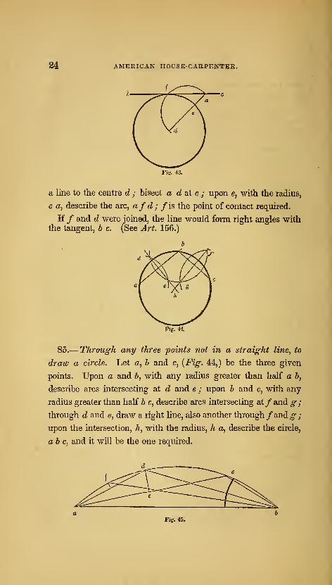
tact. Prom any point, as a, {Fig. 43,) in the tangent, b c, draw
24 AMERICAN HOUSE-CARPENTEK.
a line to the centre d ; bisect a d at e ; upon e, with the radius,
e a, describe the arc, afd;fis the point of contact required.
If / and d were joined, the line would form right angles withthe tangent, b c. (See Art. 156.)
Fig. 44.
85.— Through any three points not in a straight line, to
draw a circle. Let a, h and c, {Fig. 44,) be the three given
points. Upon a and 6, with any radius greater than half a b,
describe arcs intersecting at d and e ; upon b and c, with any
radius greater than half b c, describe arcs intersecting at/and g ;
through d and e, draw a right line, also another through/and ^;upon the intersection, h, with the radius, h a, describe the circle,
ab c, and it will be the one required.
Fig. 4&
PRACTICAL GEOMETRY. 25
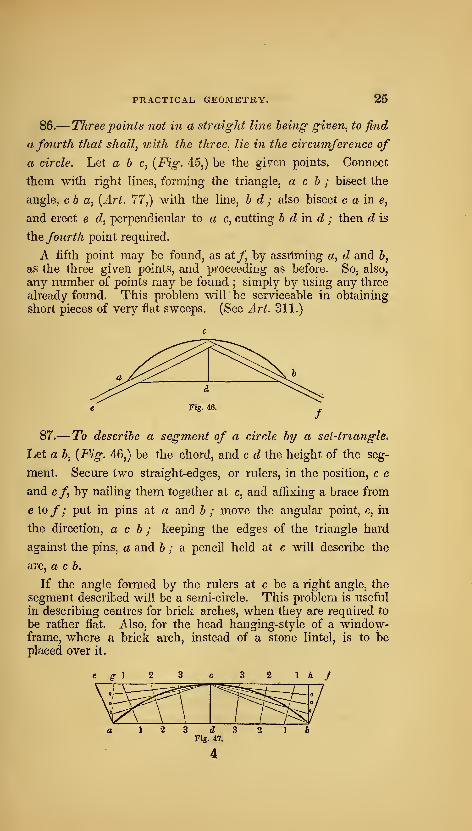
86.— Three points not in a straight line being given, to find
a fourth that shall, ivith the three, lie in the circumference of
a circle. Let a b c, {Fig. 45,) be the given points. Connect
them with right hnes, forming the triangle, a c h ; bisect the
angle, cb a, {Art. 77,) with the line, b d ; also bisect c a in e,
and erect e d, perpendicular to a c, cutting b dm. d ; then d is
the fourth point required.
A fifth point may be found, as at/, by assilming a, d and 6,
as the three given points, and proceeding as before. So, also,
any number of points may be found ; simply by using any three
already found. This problem will be serviceable in obtaining
short pieces of very flat sweeps. (See Art. 311.)
87.— To describe a segment of a circle by a sei-triangle.
Let a b, {Fig. 46,) be the chord, and c d the height of the seg-
ment. Secure two straight-edges, or rulers, in the position, c e
and cf by nailing them together at c, and affixing a brace from
e to/; put in pins at a and b ; move the angular point, c, mthe direction, a c b ; keeping the edges of the triangle hard
against the pins, a and 6 ; a pencil held at c will describe the
arc, a c b.
If the angle formed by the rulers at c be a right angle, the
segment described will be a semi-circle. This problem is useful
in describing centres for brick arches, when they are required to
be rather flat. Also, for the head hanging-style of a window-frame, where a brick arch, instead of a stone lintel, is to beplaced over it.
26 AMERICAN HOUSE-CARPENTER.
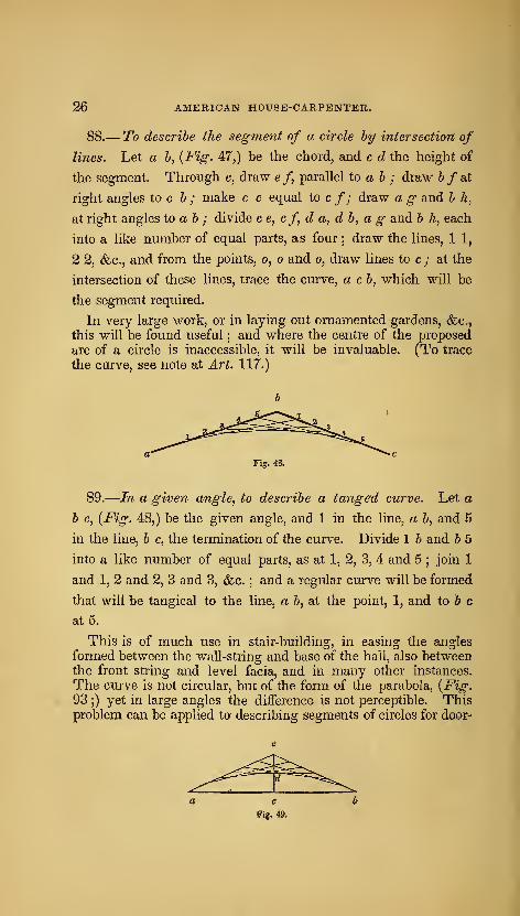
88.— To describe the segment of a circle hy intersection of
lines. Let a b, {Fig. 47,) be the chord, and c d the height of
the segment. Through c, draw ef parallel to a b ; draw 6 /at
right angles to c b ; make c e equal to c /; draw a g and b h,
at right angles to a b ; divide c e, cf d a, d b, a g and b h, each
into a like number of equal parts, as four ; draw the lines, 1 1,
2 2, &c., and from the points, o, o and o, draw lines to c ; at the
intersection of these lines, trace the curve, a cb, which will be
the segment required.
In very large work, or in laying out ornamented gardens, (fec^
this will be found useful ; and where the centre of the proposed
arc of a circle is inaccessible, it will be invaluable. (To trace
the curve, see note at Art. 117.)
Fig. 48.
89.
—
In a given angle, to describe a tanged curve. Let a
b c, {Fig. 48,) be the given angle, and 1 in the line, a b, and 5
in the line, b c, the termination of the curve. Divide 1 b and b 5
into a like number of equal parts, as at 1, 2, 3, 4 and 5;join 1
and 1, 2 and 2, 3 and 3, &c. ; and a regular curve will be formed
that will be tangical to the line, a b, at the point, 1, and to 6 c
at 5.
This is of much use in stair-building, in easing the angles
formed between the wall-string and base of the hall, also betweenthe front string and level facia, and in many other instances.
The curve is not circular, but of the form of the parabola, {Fig.
93 ;)yet in large angles the difference is not perceptible. This
problem can be applied to describing segments of circles for door-
Fig. 49.

PRACTICAL GEOMETRY. 27
heads, window-heads, &c., to rather better advantage than Art.
87. For instance, let a b, {Fig. 49,) be the width of the open-
ing, and c d the height of the arc. Extend c d, and make d e
equal to c d ; join a and e, also e and b ; and proceed as direct-
ed at Art. 89.
Fig. 50.
90.—To describe a circle within any given triangle, so that
the sides of the triangle shall be tangical. Let a b c, {Fig.
50,) be the given triangle. Bisect the angles, a and 6, according
to Art. 77 ; upon d, the point of intersection of the bisecting
lines, with the radius, d e, describe the required circle.
Fig. 51.
91.
—
About a given circle^ to describe an equi-lateral tri-
angle. Let a d b c, {Fig. 5] ,) be the given circle. Draw the
diameter, c d ; upon d, with the radius of the given circle, de-
scribe the arc, a e b ; join a and b ; drsiwfg, at right angles to
d c ; make/c and c g, each equal to a b ; from/, through a,
draw / h, also from g, through b, draw g h; thenfg h will be
the triangle required.

38 AMERICAN HOUSE-CARPENTER.
92.
—
To find a right line nearly equal to the circumference
of a circle. Let abed, {Fig. 52,) be the given circle. Draw
the diameter, a c ; on this erect an equi-lateral triangle, a e c,
according to Art. 96 ;draw gf, parallel to a c ; extend e c to/,
also e ato g ; then gf will be nearly the length of the semi-
circle, ad c ; and twice g f will nearly equal the circumference
of the circle, ab a d,SiS was required.
Lines drawn from e, through any points in the circle, as o, o
and 0, to^, p and/?, will divide^/in the same way as the semi-
circle, a d c, is divided. So, any portion of a circle may betransferred to a straight line. This is a very useful problem,and should be well studied ; as it is frequently used to solve
problems on stairs, domes, <fec.
Fig. 53.
92, a.—Another method. Let a bf c, {Fig. 53,) be the given
circle. Draw the diameter, ac ; from d, the centre, and at right
angles to a c, draw d b ; join b and c ; bisect be at e; from d,
through e, draw df; then e/ added to three times the diameter,

PRACTICAL GEOMETRY. 29
will equal the circumference of the circle within the 4^5^77 part of
its length.
POLYGONS, &C.
93.— Within a given circle, to inscribe an equi-lateral tri-
angle, hexagon or dodecagon. Let abed, {Fig. 54,) be the
given circle. Draw the diameter, b d ; upon b, with the radius
of the given circle, describe the arc, a e c ; join a and c, also a
and d, and c and d—and the triangle is completed. For the
hexagon : from a, also from c, through e, draw the lines, a fand eg; join a and b, b and c, c and/, &c., and the hexagon is
completed. The dodecagon may be formed by bisecting the
sides of the hexagon.
Each side of a regular hexagon is exactly equal to the radius
of the circle that circumscribes the figure. For the radius is
equal to a chord of an arc of 60 degrees ; and, as every circle is
supposed to be divided into 350 degrees, there is just 6 times 60,
or 6 arcs of 60 degrees, in the whole circumference. A line
drawn from each angle of the hexagon to the centre, (as in the
figure,) divides it into six equal, equi-lateral triangles.
Fig. 55.
30 AMERICAN HOUSE-CARPENTER.
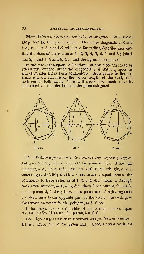
94.— Within a square to inscribe an octagon. Let abed,{Fig. 55j) be the given square. Draw the diagonals, a d and
be; upon a, 6, c and d, with a e for radius, describe arcs cut-
ting the sides of the square at 1, 2, 3, 4, 5, 6, 7 and 8 ;join 1
and 2, 3 and 4, 5 and 6, &c., and the figure is completed.
In order to eight-square a hand-rail, or any piece that is to beafterwards rounded, draw the diagonals, a d and b c, upon the
end of it, after it has been squared-up. Set a gauge to the dis-
tance, a e, and run it upon the whole length of the stuff, fromeach corner both ways. This will show how much is to bechamfered off, in order to make the piece octagonal.
Fig. 56,
95.— Within a given circle to inscribe any regular polygon.
Let a b c2, [Fig. 56, 57 and 58,) be given circles. Draw the
diameter, a c ; upon this, erect an equi-lateral triangle, a e c,
according to Art. 96 ; divide a c into as many equal parts as the
polygon is to have sides, as at 1, 2, 3, 4, &c. ; from e, through
each even number, as 2, 4, 6, &c., draw lines cutting the circle
in the points, 2, 4, &c. ; from these points and at right angles to
a c, draw lines to the opposite part of the circle ; this will give
the remaining points for the polygon, as b, /, <fcc.
In forming a hexagon, the sides of the triangle erected upona c, (as at Fig. 57,) mark the points, b and/.
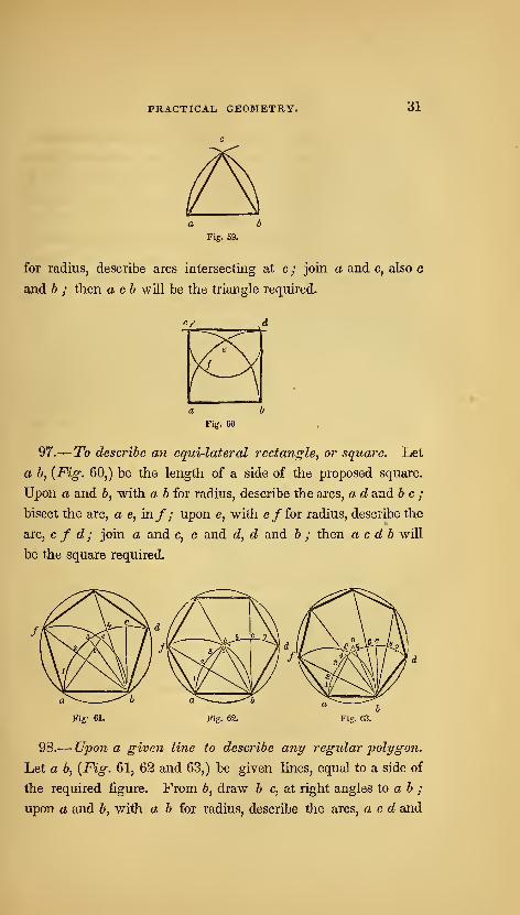
96.— Upon a given line to construct an equi-lateral triangle.
Let a b, {Fig. 59,) be the given line. Upon a and b, with a b
PRACTICAL GEOMETRY. 31
Fig. 59.
for radius, describe arcs intersecting at c ; join a and c, also c
and h ; then a ch will be the triangle required.
Fig. 60,
97.^ To describe an equi-lateral rectangle, or square. Let
a b, {Fig. 60,) be the length of a side of the proposed square.
Upon a and b, with a b for radius, describe the arcs, a d and be;
bisect the arc, a e, in/; upon e, with e/for radius, describe the
arc, c f d ; join a and c, c and d, d and 6 ; then a c d b will
be the square required.
Fig- 61. Fig. 62.
98.— Upon a given line to describe any regular polygon.
Let a 6, [Fig. 61, 62 and 63,) be given lines, equal to a side of
the required figure. From 5, draw b c, at right angles to a b ;
upon a and b, with a b for radius, describe the arcs, a c d and
32 AMERICAN HOUSE-CARPENTER.
f eh] divide a c into as many equal parts as the polygon is to
have sides, and extend those divisions from c towards d ; from
the second point of division counting from c towards a, as 3,
{Fig. 61j) 4, [Fig. 62,) and 5, {Fig. 63,) draw a line to h ; take
the distance from said point of division to a, and set it from h
to e ; join e and a ; upon the intersection, o, with the radius,
a, describe the circle, a f d b ; then radiating lines, drawn
from b through the even numbers on the arc, a d, will cut the
circle at the several angles of the required figure.
In the hexagon, {Fig. 62,) the divisions on the arc, a d, are
not necessary ; for the point, o, is at the intersection of the arcs,
a d and/ 6, the points, /and d, are determined by the intersec-
tion of those arcs with the circle, and the points above, g and k,
can be found by drawing lines from a and b, through the centre,
0. In polygons of a greater number of sides than the hexagon,the intersection, o, comes above the arcs
; in such case, therefore,
the lines, a e and b 5, {Fig. 63,) have to be extended before theywill intersect.
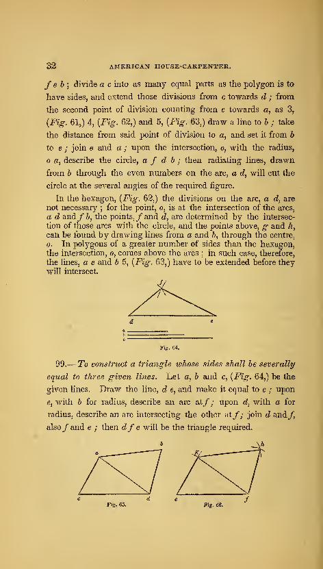
Fig. 64.
99.— To construct a triangle whose sides shall he severally
equal to three given lines. Let a, b and c, {Fig. 64,) be the
given lines. Draw the line, d e, and make it equal to c ; upon
e, with b for radius, describe an arc at/; upon d, with a for
radius, describe an arc intersecting the other at/; join d and/
also/and e ; then dfe will be the triangle required.
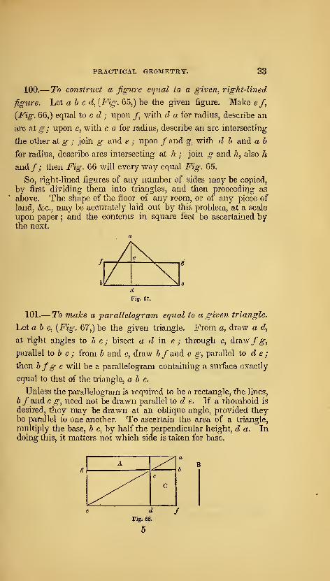
Fig. 65. Fig. 66.
PRACTICAL GEOMETRY. 33
100.
—
To construct a figure eqtial to a given, right-lined
figure. Let ah c d, {Fig- 65,) be the given figure. Make e/,
{Fig. 66,) equal to c d ; upon /, with d a for radius, describe an
arc at g ; upon e, with c a for radius, describe an arc intersecting
the other at g ; join g and e ; upon / and g, with d b and a b
for radius, describe arcs intersecting at h ; join g and h, also k
and/; then Fig. 66 will every way equal Fig. 65.
So, right-lined figures of any number of sides may be copied,
by first dividing them into triangles, and then proceeding as
above. The shape of the floor of any room, or of any piece of
land, &c., may be accurately laid out by this problem, at a scale
upon paper ; and the contents in square feet be ascertained bythe next.
Fig. 67.
101.— To make a parallelogram equal to a given triangle.
Let a b c, {Fig. 67,) be the given triangle. From a, draw a d,
at right angles to b c; bisect a d in e; through e, drawf g,
parallel to & c ; from b and c, draw b f and c g, parallel to d e ;
then bfg c will be a parallelogram containing a surface exactly
equal to that of the triangle, a b c.
Unless the parallelogram is required to be a rectangle, the lines,
bf and c g, need not be drawn parallel to d e. If a rhomboid is
desired, they may be drawn at an oblique angle, provided theybe parallel to one another. To ascertain the area of a triangle,
multiply the base, b c, by half the perpendicular height, d a. Indoing this, it matters not which side is taken for base.
A ^^^^ e
^^ C
d
Fig. 68.
5

34 AMERICAN HOUSE-CARPENTER.
102.
—
A 'parallelogram being given, to construct another
equal to it, and having a side equal to a given line. Let A,
{Fig. 68,) be the given parallelogram, and B the given line.
Produce the sides of the parallelogram, as at a, b, c and d ; make
e d equal to B ; through d, draw c /, parallel to g b ; through
e, draw the diagonal, c a ; from a, draw a /, parallel to e d;
then C will be equal to A. (See Art. 144.)
Fig 69.
103.— To make a square equal to two or more given squares.
Let A and B, {Fig. 69,) be two given squares. Place them so
as to form a right angle, as at a ; join b and c ; then the square,
C, formed upon the line, b c, will be equal in extent to the squares,
A and B, added together. Again : if a b, {Fig. 70,) be equal to
the side of a given square, c a, placed at right angles to a b, be the
side of another given square, and c d, placed at right angles to

PRACTICAL GEOMETRY. 35
c 6, be the side of a third given square;
then the square, A^
formed upon the Hne, d b, will be equal to the three given
squares. (See Art. 157.)
The usefulness and importance of this problem are proverbial.
To ascertain the length of braces and of rafters in framing, the
length of stair-strings, &c., are some of the purposes to which it
may be applied in carpentry. (See note to ArL 74, b.) If the
length of any two sides of a right-angled triangle is known, that
of the third can be ascertained. Because the square of the
hypothenuse is equal to the united squares of the two sides that
contain the right angle.
(1.)—^The two sides containing the right angle being known,to find the hypothenuse. Rule.—Square each given side, addthe squares together, and from the product extract the square-
root : this will be the answer. For instance, suppose it wererequired to find the length of a rafter for a house, 34 feet wide,
—
the ridge of the roof to be 9 feet high, above the level of the
wall-plates. Then 17 feet, half of the span, is one, and 9 feet,
the height, is the other of the sides that contain the right angle.
Proceed as directed by the rule
:
17 917 9
119 81 = square of 9.
17 289 = square of 17.
289 => square of 17. 370 Product.
1 ) 370 ( 19-235 + = square-root of 370 ; equal 19 feet, 2} in.
1 1 nearly : which would be the required— length of the rafter.
29 ) 2709 261
382)- -9002 764
3843 ) 136003 11529
38465)- 207100192325
(By reference to the table of square-roots in the appendix, the
root ot almost any number may be found ready calculated.)

36 AMERICAN HOUSE-CARPETTTER.
Again : suppose it be required, in a frame building, to find the
length of a brace, having a run of three feet each way from the
point of the right angle. The length of the sides containing the
right angle will be each 3 feet : then, as before
—
33
9 = square of one side,
3 times 3 = 9 = square of the other side.
] 8 Product : the square-root of which is 4*2426 + ft.,
er 4 feet, 2 inches and fths. full.
(2.)—The hypothenuse and one side being known, to find the
other side. Rule.—Subtract the square of the given side fromthe square of the hypothenuse, and the square-root of the product
will be the answer. Suppose it were required to ascertain the
greatest perpendicular height a roof of a given span may have,
when pieces of timber of a given length are to be used as rafters.
Let the span be 20 feet, and the rafters of 3 X 4 hemlock joist.
These come about 13 feet long. The known hypothenuse,
then, is 13 feet, and the known side, 10 feet—that being half the
span of the building.
1313
3913
169 = square of hypothenuse.
10 times 10 = 100 = square of the given side.
69 Product : the square-root of which is 8•3066 -f feet, or 8 feet, 3 inches and ^ths. full. This will bethe greatest perpendicular height, as required. Again : supposethat in a story of 8 feet, from floor to floor, a step-ladder is re-
quired, the strings of which are to be of plank, 12 feet long; and
it is desirable to know the greatest run such a length of string
will afibrd. In this case, the two given sides are—hypothenuse
12, perpendicular 8 feet.
12 times 12 = 144 = square of hypothenuse.8 times 8 = 64 = square of perpendicular.
80 Product : the square-root of which is 8'9442 -f-
feet, or 8 feet, 11 inches and fgths.—the answer, as required.

PRACTICAL GEOMETRY. 37
Many other cases might he adduced to show the utility of this
prohlem, A practical and ready method of ascertaining the
length of braces, rafters, &c., when not of a great length, is to
apply a rule across the carpenters'-square. Suppose, for the
length of a rafter, the base be 12 feet and the height 7. Applythe rule diagonally on the square, so that it touches 12 inches
from the corner on one side, and 7 inches from the corner on the
Other. The number of inches on the rule, which are intercepted
by the sides of the square, 13 f- nearly, will be the length of the
rafter in feet ; viz, 13 feet and gths of a foot. If the dimensionsare large, as 30 feet and 20, take the half of each on the sides of
the square, viz, 15 and 10 inches ; then the length in inches
across, will be one-half the number of feet the rafter is long.
This method is just as accurate as the preceding ; but whenthe length of a very long rafter is sought, it requires great care
and precision to ascertain the fractions. For the least variation
on the square, or in the length taken on the rule, would makeperhaps several inches difference in the length of the rafter.
For shorter dimensions, however, the result will be true enough.
104.— To make a circle equal to two given circles. Let Aand jB, [Fig. 71,) be the given circles. In the right-angled tri-
angle, ah c, make a h equal to the diameter of the circle, B, and
c b equal to the diameter of the circle, A ; then the hypothenuse,
Fig. 72.
38 American house-carpenter.
a c, will be the diameter of a circle, C, which will be equal in
area to the two circles, A and i?, added together.
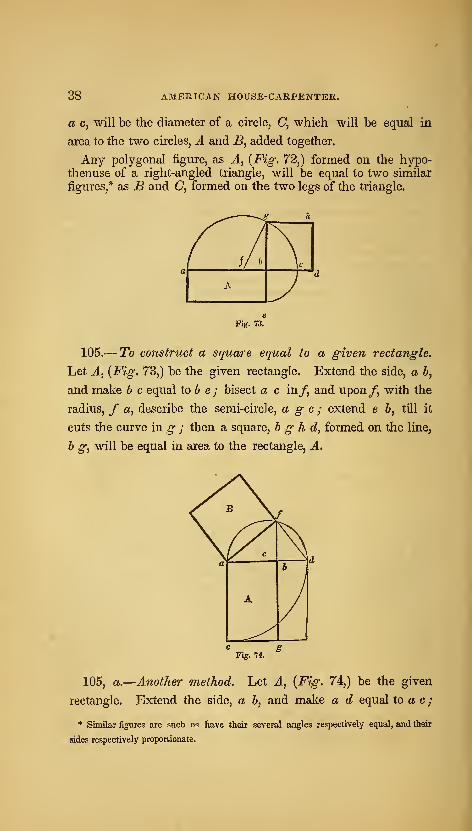
Any polygonal figure, as J[, {Fig. 72,) formed on the hypo-thenuse of a right-angled triangle, will be equal to two similar
figures,* as B and C, formed on the two legs of the triangle.
Fig. 73.
105.
—
To construct a square equal to a given rectangle.
Let J., {Fig. 73,) be the given rectangle. Extend the side, a 6,
and make h c equal to 6 e ; bisect a c in/, and upon/, with the
radius, / a, describe the semi-circle, age; extend e b, till it
cuts the curve in g ; then a square, h g h d, formed on the line,
h g, will be equal in area to the rectangle, A.
e
b
A
« 8Fig. 74.
105, a.—Another method. Let J., {Fig. 74,) be the given
rectangle. Extend the side, a b, and make a d equal to a c
;
* Sinular figures are such as have their several angles respectively equal, and their
Bides respectively proportionate.
PRACTICAL GEOMETRY. 39
bisect a din e ; upon e, with the radius, e a, describe the semi-
circle, afd; extend^ h till it cuts the curve in/; join a and
/; then the square, B, formed on the line, a/, will be equal in
area to the rectangle, A. (See Art. 156 and 157.)
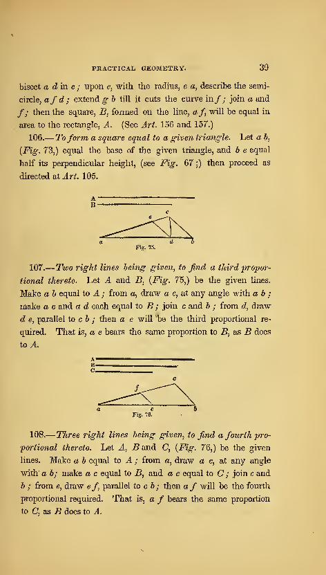
106.— Toform a square equal to a given triangle. Let a b,
{Fig. 73,) equal the base of the given triangle, and b e equal
half its perpendicular height, (see Fig. 67 ;) then proceed as
directed at Art. 105.
Fig. 75.
107.—Two right lines being given, to find a third jtropor-
tional thereto. Let A and B, [Fig. 75,) be the given lines.
Make a b equal to A ; from a, draw a c, at any angle with a b ;
make a c and a d each equal to B ; join c and b ; from d, draw
d e, parallel to c b ; then a e will be the third proportional re-
quired. That is, a e bears the same proportion to B, as B does
to A.
Fig. 76.
108.
—
Three right lines being given, to find a fourth jpro-
portional thereto. Let A, B and C, {Fig. 76,) be the given
lines. Make a b equal to A ; from a, draw a c, at any angle
with a b; make a c equal to B, and a e equal to C ; join c and
b ; from e, draw e /, parallel to c b ; then a f will be the fourth
proportional required. That is, a f bears the same proportion
to C, as B does to A.
40 AMERICAN HOUSE-CARPENTER.
To apply this problem, suppose the two axes of a given ellipsis,
and the longer axis of a proposed ellipsis are given. Then, bythis problem, the length of the shorter axis to the proposed ellip-
sis, can be found ; so that it will bear the same proportion to the
longer axis, as the shorter of the given ellipsis does to its longer.
(See also, Art. 126.)
c
a 1 2 3 4 5 6
Fig. 77.
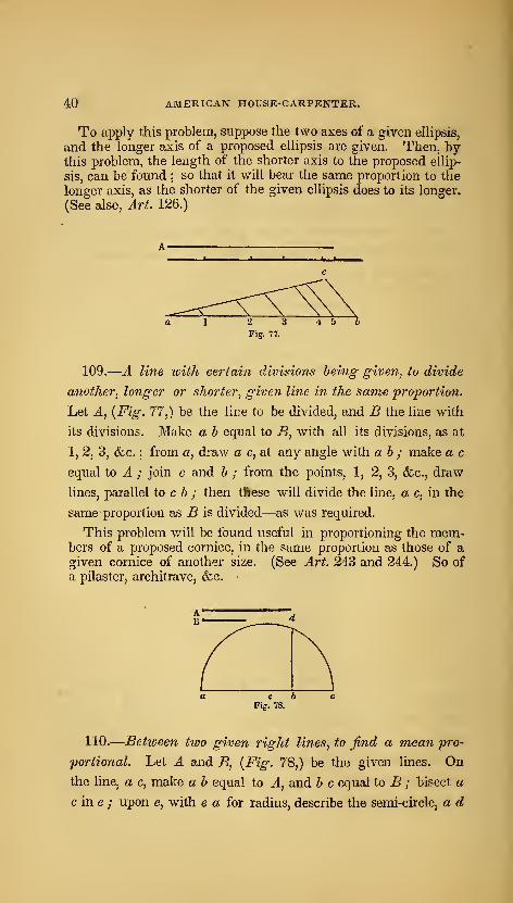
109.
—
A line with certain divisions being given, to divide
another, longer or shorter, given line i?i the same proportion.
Let A, {Fig. 77,) be the line to be divided, and B the line with
its divisions. Make a b equal to B, with all its divisions, as at
1, 2, 3, &c. ; from a, draw a c, at any angle with a b ; make a c
equal to A ; join c and b ; from the points, 1, 2, 3, (fee, draw
lines, parallel to c b ; then tftese will divide the line, a c, in the
same proportion as B is divided—as was required.
This problem will be found useful in proportioning the mem-bers of a proposed cornice, in the same proportion as those of agiven cornice of another size. (See Art. 243 and 244.) So of
a pilaster, architrave, &c. •
Fig. 78.
110.
—
Between two given right lines, to find a mean pro-
portional. Let A and B, {Fig. 78,) be the given lines. Onthe line, a c, make a b equal to A, and b c equal to B ; bisect a
c in e ; upon e, with e a for radius, describe the semi-circle, a d
PRACTICAL GEOMETRY. 41
c ; at h, erect h d, at right angles to a c; then b d will be the
mean proportional between A and B.
For an application of this problem, see Art. 105.
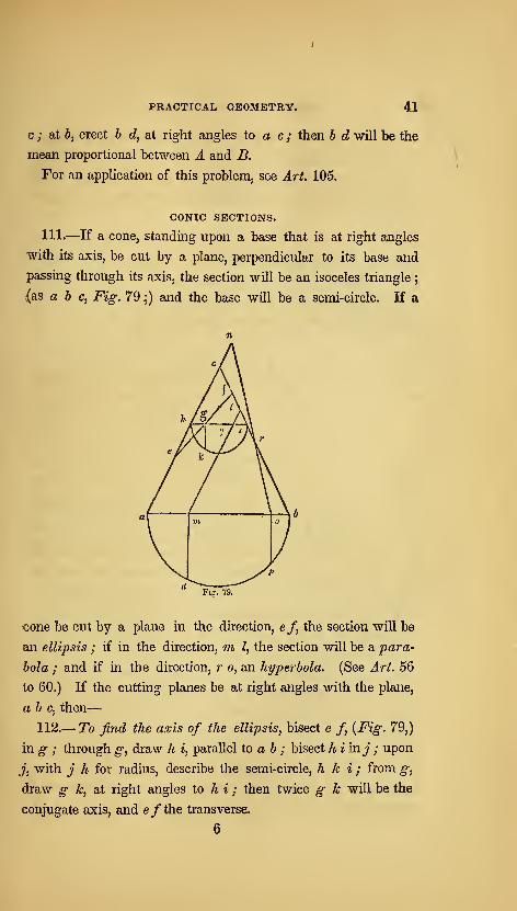
CONIC SECTIONS.
111.—If a cone, standing upon a base that is at right angles
with its axis, be cut by a plane, perpendicular to its base and
passing through its axis, the section will be an isoceles triangle;
{as a b c, Fig. 79 ]) and the base will be a semi-circle. If a
€one be cut by a plane in the direction, e/, the section will be
an ellipsis ; if in the direction, m, I, the section will be a para-
bola ; and if in the direction, r o, an hyperbola. (See Art. 56
to 60.) If the cutting planes be at right angles with the plane,
a 6 c, then
—
112.— To find the axis of the ellipsis^ bisect e /, {Fig. 79,)
in g ; through g, draw h i, parallel to a b ; bisect hiinj ; upon
j, with j h for radius, describe the semi-circle, h k i ; from g,
draw g A:, at right angles to h i ; then twice g k will be the
conjugate axis, and e/the transverse.
6

42 AMERICAN HOUSE-CARPENTER.
113.— To find the axis and base of the parabola. Let fn I,
{Fig. 79,) parallel to a c, be the direction of the cutting plane.
From m, draw m d, at right angles to a b ; then I m will be the
axis and height, and m d an. ordinate and half the base ; as at
Fig. 92, 93.
114.— To find the height, base and transverse axis of anhyperbola. Let o r, {Fig. 79,) be the direction of the cutting
plane. Extend o r and a c till they meet at n ; from o, draw
o p, at right angles to a b; then ro will be the height, nr the
transverse axis, and o p half the base ; as at Fig. 94.
115.— The axis being given, to find the foci, and to describe
an ellipsis with a string. Let a b, {Fig. 80,) and c d, be the
given axes. Upon c, with a e or 6 e for radius, describe the arc,
ff; then/and/, the jooints at which the arc cuts the transverse
axis, will be thefoci. At/ and /place two pins, and another at c ;
tie a string about the three pins, so as to form the triangle, //c /
remove the pin from c, and place a pencil in its stead ; keeping the
string taut, move the pencil in the direction, eg a; it will then
describe the required ellipsis. The hnes,fg and g f, show tha
position of the string when the pencil arrives at g.
This method, when performed correctly, is perfectly accurate
;
but the string is liable to stretch, and is, therefore, not so good to
nse as the trammel. In making an ellipse by a string or twine,
that kind should be used which has the least tendency to elasticity.
For this reason, a cotton cord, such as chalk-lines are commonlymade of, is not proper for the purpose : a linen, or flaxen cord ia
much better.
PRACTICAL GEOMETRY. 43
Fig. 81
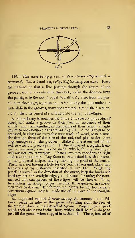
116.—The axes being given, to describe an ellipsis with a
trammel. Let a b and c d, {Fig. 81,) be the given axes. Place
the trammel so that a line passing through the centre of the
grooves, virould coincide with the axes;make the distance from
the pencil, e, to the nut,/^ equal to half c d ; also, from the pen-
cil, e, to the nut, g, equal to half a b ; letting the pins under the
nuts slide in the grooves, move the trammel, e g, in the direction,
c b d ; then the pencil at e will describe the required ellipse.
A trammel may be constructed thus : take two straight strips of
board, and make a groove on their face, in the centre of their
width;join them together, in the middle of their length, at right
angles to one another ; as is seen at Fig. 81. A rod is then to beprepared, having two moveable nuts made of wood, with a mor-tice through them of the size of the rod, and pins under themlarge enough to fill the grooves. Make at hole at one end of the
rod, in which to place a pencil. In the absence of a regular tram-
mel, a temporary one may be made, which, for any short job^
will answer every purpose. Fasten two straight-edges at right
angles to one another. Lay them so as to coincide with the axes
of the proposed ellipse, having the angular point at the centre.
Then, in a rod having a hole for the pencil at one end, place twobrad-awls at the distances described at J.r^. 116. While the
pencil is moved in the direction of the curve, keep the brad-awls
hard against the straight-edges, as directed for using the tram-
mel-rod, and one-quarter of the ellipse will be drawn. Then,by shifting the straight-edges, the other three quarters in succes-
sion may be drawn. If the required ellipse be not too large, acarpenters'-square may be made use of, in place of the straight-
edges.
An improved method of constructing the trammel, is as fol-
lows : make the sides of the grooves bevilling from the face ofthe stuff, or dove-tailing instead of square. Prepare two slips ofwood, each about two inches long, which shall be of a shape to
just fill the groove when slipped in at the end. These, instead of
u AMERICAN HOUSE-CARPENTER.
pins, are to be attached one to each of the moveable nuts with
a screw, loose enough for the nut to move freely about the screw
as an axis. The advantage of this contrivance is, in preventing
the nuts from slipping out of their places, during the operation
of describing the curve.
'^%
^y^ n
/ 3 2 1 e 1 2 ')
nV ^D1 2 3 A
i d I
Fig. 82.
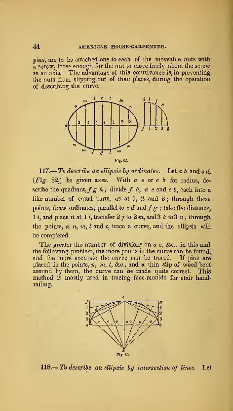
117.
—
To describe an ellipsis by ordinates. Let a b and c c?,
{Fig. 82,) be given axes. With a e or e 6 for radius, de-
scribe the quadrant,/^ h; divide /A, a e and e 6, each into a
like number of equal parts, as at 1, 2 and 3 ; through these
points, draw ordinates, parallel to c d andfg- ; take the distance,
1 *, and place it at 1 1, transfer 2j to 2 m, and 3 kto3 n; through
the points, a, n, m, I and c, trace a curve, and the ellipsis will
be completed.
The greater the number of divisions on a e, &c., in this andthe following problem, the more points in the curve can be found,
and the more accurate the curve can be traced. If pins are
placed in the points, n, m, I, &.C., and a thin slip of wood bentaround by them, the curve can be made quite correct. Thismethod is mostly used in tracing face-moulds for stair hand-railing.
118.
—
To describe an ellipsis by intersection of lines. Let
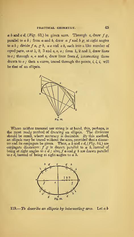
PRACTICAL GEOMETRY. 45
a b and c d, {Fig. 83,) be given axes. Through c, draw f g,
parallel to ah ; from a and 6, draw a / and h g, at right angles
to ab ; divide f a, g b, ae and e 6, each into a like number of
equal parts, as at 1, 2, 3 and o, o, o ; from 1, 2 and 3, draw lines
to c ; through o, o and o, draw lines from d, intersecting those
drawn to c ; then a curve, traced through the points, i, i, i, will
be that of an ellipsis.
Where neither trammel nor string is at hand, this, perhaps, is
the most ready method of drawing an ellipsis. The divisions
should be small, where accuracy is desirable. By this method,
an ellipsis may be traced without the axes, provided that a diame-
ter and its conjugate be given. Thus, a b and c d, {Fig. 84,) are
conjugate diameters : f g is drawn parallel to a b, instead of
being at right angles to c c^ ; also, / a andg b are drawn parallel
to c d, instead of being at right angles to ah.
119.
—
To describe an ellipsis by intersecting arcs. Let a b
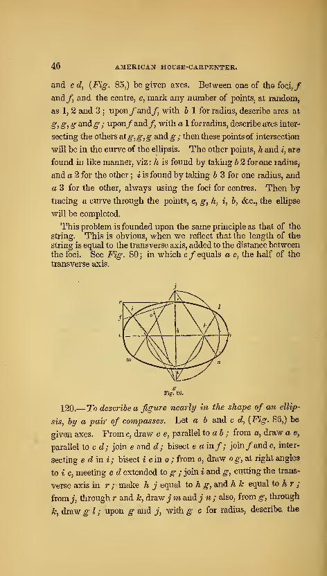
46 AMERICAN HOUSE-CARPENTER.
and c d, {Fig. 85,) be given axes. Between one of the foci,/
and/, and the centre, e, mark any number of points, at random,
as 1, 2 and 3 ; upon/and/ with h 1 for radius, describe arcs at
g, g,g andg ; upon/and/ with a 1 for radius, describe arcs inter-
secting the others at g^ g,g andg ; then these points of intersection
will be in the cm-ve of the ellipsis. The other points, h and i, are
found in like manner, viz: h is found by taking b 2 for one radius,
and a 2 for the other ; i is found by taldng b 3 for one radius, and
a 3 for the other, always using the foci for centres. Then by
tracing a curve through the points, c, g, h, i, b, &c., the ellipse
will be completed.
This problem is founded upon the same principle as that of the
string. This is obvious, when we reflect that the length of the
string is equal to the transverse axis, added to the distance betweenthe foci. See Fig. 80 ; in which c/ equals a e, the half of the
transverse axis.
120.
—
To describe a figure nearly in the shape of an ellip-
sis, by a pair of compasses. Let a b and c d, {Fig. 86,) be
given axes. From c, draw c e, parallel to ab ; from a, draw a e,
parallel to c d; join e and c?; bisect e a in/; join/and c, inter-
secting e dini; bisect icino; from o, draw og, at right angle*
to i c, meeting c d extended to g ; join i and g, cutting the trans-
verse axis in r ; make h j equal to h g, and h k equal to h r ;
from 7, through r and k, draw jm andj n ; also, from g, through
k, draw g I; upon g and jV with g c for radius, describe the
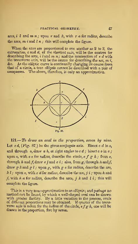
PRACTICAL GEOMETRY. 47
arcs, i I and m n; upon r and k, with r a for radius, describe
the arcs, m, i and I n ; this will complete the figure.
When the axes are proportioned to one another as 2 to 3, theextremities, c and d, of the shortest axis, will be the centres for
describing the arcs, i I and m n ; and the intersection of e d withthe transverse axis, will be the centre for describing the arc, m i,
&c. As the elliptic curve is continually changing its course fromthat of a circle, a true ellipsis cannot be described with a pair ofcompasses. The above, therefore, is only an approximation.
121.— To draw an oval in the proportion, seven by nine.
Let c d, {Pig. 87,) be the given conjugate axis. Bisect c d ino,
and through o, draw a b, at right angles to c d ; bisect c o in e ;
upon 0, with o e for radius, describe the circle, e f g- h; from e,
through h and/, draw e j and e i ; also, from g, through h and/,
draw g k and g I ; upon g, with g c far radius, describe the arc,
k I ; upon e, with e d for radius, describe the arc, j i ; upon h and
/, with h a for radius, describe the arcs, j k and I i; this will
complete the figure.
This is a very near approximation to an ellipsis ; and perhaps nomethod can be found, by which a well-shaped oval can be drawnwith greater facility. By a little variation in the process, ovalsof different proportions may be obtained. If quarter of the trans-
verse axis is taken for the radius of the circle, efg h, one will bedrawn in the proportion, five by seven.
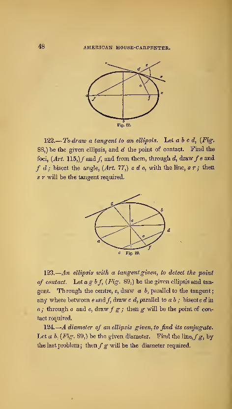
48 AMERICAN HOUSE-CARPENTER.
122.
—
To draw a tangent to an ellipsis. Let abed, {Fig:
88,) be the given ellipsis, and d the point of contact. Find the
foci, {Art. 115,)/ and/, and from them, through d, draw/e and
f d; bisect the angle, {Art. 77,) e d o, with the line, sr; then
5 r will be the tangent required.
c Fig. 89.
123.
—
An ellipsis with a tangentgiven, to detect the point
of contact, hetagbf, {Fig. 89,) be the given ellipsis and tan-
gent. Through the centre, e, draw a b, parallel to the tangent
;
any where between e and/, draw c d, parallel to ab ; bisect cd in
; through o and e, drsLWf g ; then g will be the point of con-
tact required.
124.
—
A diameter of an ellipsis given, to find its conjugate.
Let a b, {Fig. 89,) be the given diameter. Find the ]me,fg, by
the last problem; thenfg will be the diameter required.
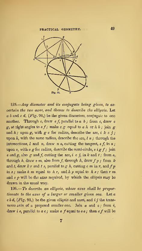
PRACTICAL GEOMETRY. 49
Fig. 90. d
125.
—
Any diameter and its conjugate being given, to as-
certain the two axes, and thence to describe the ellipsis. Let
a b and c d, {Fig. 90,) be the given diameters, conjugate to one
another. Through c, draw e /, parallel to a b ; from c, draw c
g, at right angles to ef; make c g equal to a h ox hb ; join gand h ; upon g, with ^ c for radius, describe the arc, i k c j ;
upon h, with the same radius, describe the arc. In; through the
intersections, I and n, draw n o, cutting the tangent, ef, in o ;
upon 0, with o gfov radius, describe the semi-circle, eigf ; join
e and^, also g and/, cutting the arc, i c j, in k and ^; from e,
through h, draw e *;*, also from/, through h, draw/p ; from A;
and t, draw A: r and t s, parallel to^ h., cutting e ni in r, and/^
in s ; make h m equal to h r, and A _p equal to h s ; then r 7n>
and 5 p will be the axes required, by which the ellipsis may be
drawn in the usual way.
126.— To describe an ellipsis, whose axes shall be propor-
tionate to the axes of a larger or smaller given one. Let a
cbd, {Fig. 91,) be the given ellipsis and axes, and ij the trans-
verse axis of a proposed smaller one. Join a and c ; from i,
draw i e, parallel to ac ; make o f equal tooe ; then e/ will be

m AMERICAN HOUSE-CARPENTER.
Fig. 91.
the conjugate axis required, and will bear the same proportion to
ij, asc d does to a h, (See Art. 108.)
1 2 3 3 2 1
o\^^ V?
i^[^7 \^
a ^
e
1n \k
\e
1 \d 1 2 3 m 3
Fig. 92.
2 1 <f
127.— To describe a parabola by intersection of lines. Let
m I, {Fig. 92j) be the axis and height, (see Fig. 79,) and c? c?, a
double ordinate and base of the proposed parabola. Through /,
draw a a, parallel to d d ; through d and d, draw d a and d a,
parallel to ml ; divide a d and d m, each into a like number of
equal parts ; from each point of division in d m, draw the lines,
1 1, 2 2, &c., parallel to ml; from each point of division in d
a, draw lines to I ; then a curve traced through the points of
intersection, o, o and o, will be that of a parabola.
127, a.—Another method. Let m l, {Fig. 93,) be the axis and
height, and d d the base. Extend m I, and make I a equal to mI ; join a and d, and a and d ; divide a d and a d, each into a
like number of equal parts, as at 1, 2, 3, &c.;join 1 and 1, 2 and
2, d&c,, and the parabola will be completed,
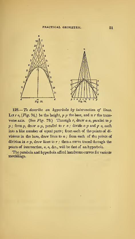
PRACTICAL GEOMETRY. 61
nV m'4W
\!v®
3/ ^9
3/ VlO
/\ll
Tis. 93.
p \ -i i o ^Fig. 94.
128.— To describe an hyperbola by intersection of lines.
Let r 0, {Fig. 94,) be the height, p p the base, and n r the trans-
verse axis. (See Fig. 79.) Through r, draw a a, parallel to pp ; fromp, draw ap^ parallel to r 0; divide ap andp 0, each
into a like number of equal parts ; from each of the points of di-
visions in the base, draw lines to n ; from each of the points of
division in a p, draw lines to r ; then a curve traced through the
points of intersection, 0, 0, <fec., will be that of an hyperbola.
The parabola and hyperbola aflford handsome curves for various
mouldings.
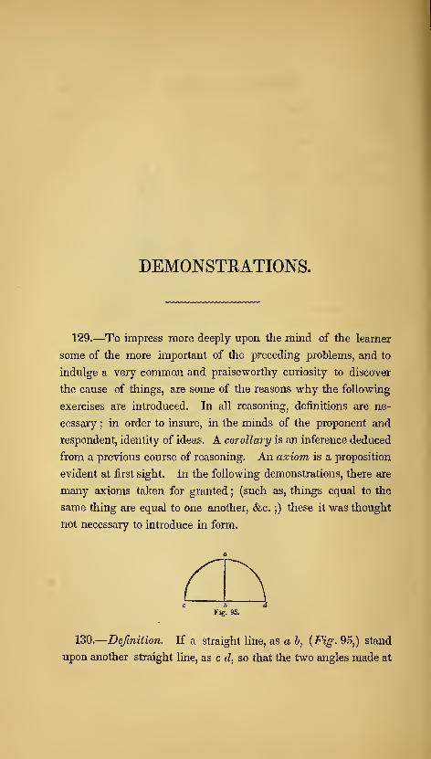
DEMONSTRATIONS.
129.—To impress more deeply upon the mind of the learner
some of the more important of the preceding problems, and to
indulge a very common and praiseworthy curiosity to discover
the cause of things, are some of the reasons why the following
exercises are introduced. In all reasoning, definitions are ne-
cessary ; in order to insure, in the minds of the proponent and
respondent, identity of ideas. A corollary is an inference deduced
from a previous course of reasoning. An axiom is a proposition
evident at first sight. In the following demonstrations, there are
many axioms taken for granted;(such as, things equal to the
same thing are equal to one another, &c. ;) these it was thought
not necessary to introduce in form.
6
Fig. 95.
130.
—
Definition. If a straight line, as a b, {Fig, 95,) stand
upon another straight line, as c d, so that the two angles made at
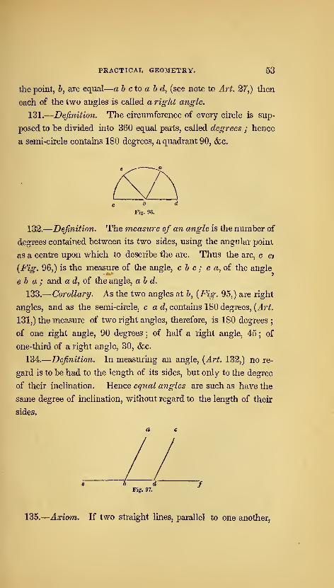
PRACTICAL GEOMETRY. 53
the point, b, are equal
—
a b do a b d, (see note to Ari. 27,) then
each of the two angles is called a right angle.
131.
—
Deftnitioii. The circumference of every circle is sup-
posed to be divided into 360 equal parts, called degrees ; hence
a semi-circle contains 180 degrees, a quadrant 90, &,c.
Fiff. 96.
132.
—
Definition. The measure of an angle is the number of
degrees contained between its two sides, using the angular point
as a centre upon which to describe the arc. Thus the arc, c e>
{Fig. 96,) is the measure of the angle, c b e ; e a, of the angle
e b a ; and a d, of the angle, ab d.
133.
—
Corollary. As the two angles at 6, {Fig. 95,) are right
angles, and as the semi-circle, cad, contains 180 degrees, {Art.
131,) the measure of two right angles, therefore, is 180 degrees;
of one right angle, 90 degrees ; of half a right angle, 45 ; of
one-third of a right angle, 30, &c.
134.
—
Definition. In measuring an angle, {Art. 132,) no re-
gard is to be had to the length of its sides, but only to the degree
of their inclination. Hence eqnal angles are such as have the
same degree of inclination, without regard to the length of their
sides.
6 dFig. 97.
135.
—
Axiom. If two straight lines, parallel to one another,
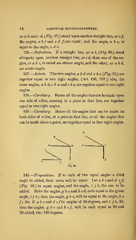
54 AMERICAN HOUSE-CARPENTER.
as a 6 andc d, {Fig. 97,) stand upon another straight line, as e/,
the angles, ahf and c d f^ are equal ; and the angle, a b e, is
equal to the angle, c d e.
136.
—
Definition. If a straight line, as a h, {Fig. 96,) stand
obliquely upon another straight line, as c d, then one of the an-
gles, as a & c, is called an obtuse angle, and the other, as ab d,
an acute angle.
137.
—
Axiom. The two angles, ah d and a he, {Fig. 96,) are
together equal to two right angles, {Art. 130, 133 ;) also, the
three angles, ah d, eh a and cb e, are together equal to two right
angles.
138.
—
Corollary. Hence all the angles that can be made upon
one side of a line, meeting in a point in that line, are together
equal to two right angles.
139.
—
Corollary. Hence all the angles that can be made on
both sides of a line, at a point in that line, or all the angles that
can be made about a point, are together equal to four right angles.
b d
140.
—
Proposition. If to each of two equal angles a third
angle be added, their sums will be equal. Let ah c and d ef,
{Fig. 98,) be equal angles, and the angle, i j k, the one to be
added. Make the angles, gb a and hed, each equal to the given
angle, ij k ; then the angle, gb c, will be equal to the angle, h e
f; for, ii ah c and d e/be angles of 90 degrees, and i j k, 30,
then the angles, gb c and h ef, will be each equal to 90 and
30 added, viz : 120 degrees.
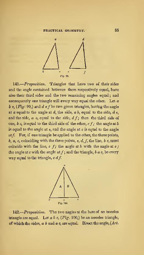
PRACTICAL GEOMETRY.
a d
55
141.
—
Proposition. Triangles that have two of their sides
and the angle contained between them respectively equal, have
also their third sides and the two remaining angles equal ; and
consequently one triangle will every way equal the other. Let a
h c, {Fig. 99,) and d efhe two given triangles, having the angle
at a equal to the angle at d, the side, a b, equal to the side, d e,
and the side, a c, equal to the side, df; then the third side of
one, b c, is equal to the third side of the other, ef; the angle at b
is equal to the angle at e, and the angle at c is equal to the angle
at/. For, if one triangle be applied to the other, the three points,
b, a, c, coinciding with the three points, e, d, f, the line, b c, must
coincide with the line, e /; the angle at b with the angle at e ;
the angle at c with the angle at/ ; and the triangle, 6 a c, be every
way equal to the triangle, e df.
142.
—
Proposition. The two angles at the base of an isoceles
triangle are equal. Let ab c, {Fig. 100,) be an isoceles triangle,
oC which the sides, a b and a c, are equal. Bisect the angle, {Art.
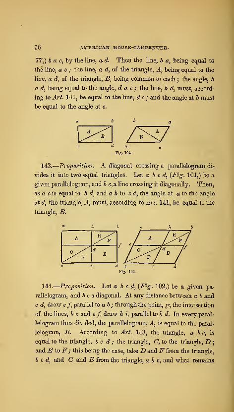
56 AMERICAN HOUSE-CARPENTER.
77,) b a c, by the line, a d. Then the Hne, h a, being equal to
the line, a c ; the line, a d, of the triangle, A, being equal to the
line, a d, of the triangle, B, being common to each ; the angle, b
a d, being equal to the angle, d a c ; the line, b d, must, accord-
ing to Art. 141, be equal to the line, dc; and the angle at 6 must
be equal to the angle at c.
Fig. 101.
143.
—
Proposition. A diagonal crossing a parallelogram di-
vides it into two equal triangles. Let abed, {Fig. 101,) be a
given parallelogram, and 6 c, a line crossing it diagonally. Then,
as a c is equal to 6 d, and a b to c d, the angle at a to the angle
at d, the triangle, A, must, according to Art. 141, be equal to the
triangle, B.
A ^^^y^^
^^ DS
B
144.
—
Proposition. Let abed, {Fig. 102,) be a given pa-
rallelogram, and 6 c a diagonal. At any distance between a b and
c d, draw e f, parallel to ab; through the point, g, the intersection
of the lines, b c and e f, draw h i, parallel to b d. In every paral-
lelogram thus divided, the parallelogram, A, is equal to the paral-
lelogram, B. According to Art. 143, the triangle, a & c, is
equal to the triangle, bed; the triangle, C, to the triangle, D;
and EtoF; this being the case, take D andF from the triangle,
bed, and C and E from the triangle, ab e, and what remains

PRACTICAL GEOMETRY. 5r
in one must be equal to what remains in the other ; therefore, the
parallelogram, A, is equal to the parallelogram, B.
Fig. 103.
145.
—
Proposition. Parallelograms standing upon the same
base and between the same parallels, are equal. Let abed and
efcd, {Fig-. 103,) be given parallelograms, standing upon the
same base, c d, and between the same parallels, a f and c d.
Then, ab and e/ being equal to c d, are equal to one another;
b e being added to both a b and ef, a e equals b f; the line, a c,
being equal to b d, and a e to bf, and the angle, c a e^ being
equal, {Art. 135,) to the angle, db f, the triangle, a e c^ must be
equal, {Art. 141,) to the triangle, bf d ; these two triangles being
equal, take the same amount, the triangle, beg, from each, and
what remains in one, ab g c, must be equal to what remains in
the other, efdg; these two quadrangles being equal, add the
same amotint, the triangle, c g d, to each, and they must still be
equal ; therefore, the parallelogram, abed, is equal to the' paral-
lelogram, efcd.
146.
—
Corollary. Hence, if a parallelogram and triangle stand
upon the same base and between the same parallels, the parallelo-
gram will be equal to double the triangle. Thus, the paral-
lelogram, a d, {Fig. 103,) is double, {Art. 143,) the triangle,
c e d.
147.
—
Proposition. Let abed, {Fig. 104,) be a given quad-
rangle with the diagonal, a d. From b, draw b e, parallel toa d;
extend cdto e ; join a and e ; then the triangle, a ec, will be equal
in area to the quadrangle, abed. Since the triangles, adb and
a d e, stand upon the same base, a d, and between the same paral-
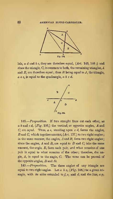
58 AMERICAN HOUSE-CARPENTER.
lels, a d and b e, they are therefore equal, {Art. 145, 146 ;) and
since the triangle, C, is common to both, the remaining triangles, Aand B, are therefore equal ; then B being equal to A, the triangle,
a e c, is equal to the quadrangle, abed.
Fig. 105.
148.
—
Proposition. If two straight lines cut each other, as
a b and c d, {Fig. 105,) the vertical, or opposite angles, A and
C, are equal. Thus, a e, standing upon c d, forms the angles,
B and C, which together amount, {Art. 137,) to two right angles
;
in the same manner, the angles, A and B, form two right angles
;
since the angles, A and B, are equal to B and C, take the same
amount, the angle, B, from each pair, and what remains of one
pair is equal to what remains of the other ; therefore, the an-
gle, A, is equal to the angle, C. The same can be proved of
the opposite angles, B and D.
149.
—
Proposition. The three angles of any triangle are
equal to two right angles. Let a b c, {Fig. 106,) be a given tri-
angle, with its sides extended to/, e, and dy and the line, egj

PRACTICAL GEOMETRY. 69
Fig. 106.
drawn parallel to & e. As g c is parallel to e b, the angle, g c dj
is, equal, [Art. 135,) to the angle, e hd ; as the lines, /c and h e,
cut one another at a, the opposite angles, f a e and b a c, are
equal, {Art. 148 ;) as the angle, / a e, is equal, (J.rf. 135,) to the
angle, a eg, the angle, a c ^, is equal to the angle, b a c ; there-
fore, the three angles meeting at c, are equal to the three angles
of the triangle, a b c ; and since the three angles at c are equal,
{Art. 137,) to two right angles, the three angles of the triangle, a
b c, must likewise be equal to two right angles. Any triangle
can be subjected to the same proof.
150.
—
Corollary. Hence, if one angle of a triangle be a right
angle, the other two angles amount to just one right angle.
151.
—
Corollary. If one angle of a triangle be a right angle,
and the two remaining angles are equal to one another, these are
each equal to half a right angle.
152.
—
Corollary. If any two angles of a triangle amount to
a right angle, the remaining angle is a right angle.
153.
—
Corollary. If any two angles of a triangle are together
equal to the remaining angle, that remaining angle is a right
angle.
154.
—
Corollary. If any two angles of a triangle are each
equal to two-thirds of a right angle, the remaining angle is also
equal to two-thirds of a right angle.
155.
—
Corollary. Hence, the angles of an equi-lateral trian-
gle, are each equal to two-thirds of a right angle.
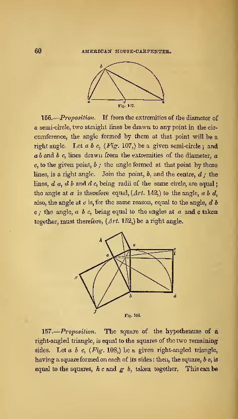
60 AMERICAN HOUSE-CARPENTER.
b
Fig. 107.
156.—Proposition. If from the extremities of the diameter of
a semi-circle, two straight lines be drawn to any point in the cir-
cumference, the angle formed by them at that point will be a
right angle. Let ah c, {Fig. 107,) be a given semi-circle; and
a b and b c, lines drawn from the extremities of the diameter, a
c, to the given point, b ; the angle formed at that point by these
lines, is a right angle. Join the point, 6, and the centre, d ; the
lines, d a, d b and d c, being radii of the same circle, are equal
;
the angle at a is therefore equal, (Art. 142,) to the angle, ab d,
also, the angle at c is, for the same reason, equal to the angle, d h
c ; the angle, a b c, being equal to the angles at a and c taken
together, must therefore, {Art. 152,) be a right angle.
Fig. 108.
157.—Proposition. The square of the hypothenuse of a
right-angled triangle, is equal to the squares of the two remaining
sides. Let a b c, {Fig: 108,) be a given right-angled triangle,
having a square formed on each of its sides : then, the square, b e, is
equal to the squares, h c and g b, taken together. This can be

PRACTICAL GEOMETRY. 61
provedby showing that the parallelogram, h I, is equal to the square,
gb ; and that the parallelogram, c I, is equal to the square, h c. The
angle, c b d,is a. right angle, and the angle, « 6 /, is a right angle;
add to each of these the angle, ab c; then the angle,/ b c, will evi-
dently be equal, {Art. 140,) to the angle, abd ; the triangle,/ 6 c,
and the square, g- &, being both upon the samebase,/6, andbetween
the same parallels, / b and^ c, the square, g b, is equal, {Art. 146,)
to twice the triangle,fbc; the triangle, abd, and the parallelo-
gram, b Z, being both upon the same base, b d, and between the
same parallels, b d and a I, the parallelogram, b I, is equal to twice
the triangle, abd; the triangles,/ 6 c and abd, being equal to
one another, {Art. 141,) the square, g b, is equal to the parallelo-
gram, b I, either being equal to twice the triangle,/ 6 c or a b d.
The method of proving h c equal to c Z is exactly similar—thus
proving the square, b e, equal to the squares, k c and g b, taken
together.
This problem, which is the 47th of the First Book of Euclid,
is said to have been demonstrated first by Pythagoras. It is sta-
ted, (but the story is of doubtful authority,) that as a thank-offer-
ing for its discovery he sacrificed a hundred oxen to the gods.
From this circumstance, it is sometimes called the hecatomb pro-
blem. It is of great value in the exact sciences, more especially
in Mensuration and Astronomy, in which many otherwise intri-
cate calculations are by it made easy of solution.
These demonstrations, which relate mostly to the problems pre-
viously given, are introduced to satisfy the learner in regard to
their mathematical accuracy. By studying and thoroughly un-
derstanding them, he will soonest arrive at a knowledge of their
importance, and be likely the longer to retain them in memory.
Should he have a relish for such exercises, and wish to continue
them farther, he may consult Euclid's Elements, in which the
whole subject of theoretical geometry is treated of in a manner
sufficiently intelligible to be understood by the young mechanic.

62 AMERICAN HOUSE-CARPENTER.
The house-carpenterj especially, needs information of this kind,
and were he thoroughly acquainted with the principles of geome-
try, he would be much less liable to commit mistakes, and be
better qualified to excel in the execution of his often difficult un-
dertakings.
SECTION II.—ARCHITECTURE.
HISTORY OP ARCHITECTURE.
158.—Architecture has been defined to be—" the art of build-
ing ;" but, in its common acceptation, it is—" the art of designing
and constructing buildings, in accordance with such principles as
constitute stability, utility and beauty." The literal signification
of the Greek word archi-tecton, from which the word architect
is derived, is chief-carpenter ; but the architect has always been
known as the chief designer rather than the chief builder. Of
the three classes into which architecture has been divided—viz.,
Civil, Military, and Naval, the first is that which refers to the
construction of edifices known as dwellings, churches and other
public buildings, bridges, &c.j for the accommodation of civilized
man—and is the subject of the remarks which follow.
159.—This is one of the most ancient of the arts : the scrip-
tures inform us of its existence at a very early period. Cain,
the son of Adam,—" builded a city, and called the name of the
city after the name of his son, Enoch"—but of the peculiar style
or manner of building we are not informed. It is presumed that
it was not remarkable for beauty, but that utility and perhaps sta-
bility were its characteristics. Soon after the deluge—that me-

64 AMERICAN house<;arpenteii.
morable event, which removed from existence all traces of the
works of man—the Tower of Babel was commenced. This was
a work of such magnitude that the gathering of the materials,
according to some writers, occupied three years ; the period from
its commencement until the work was abandoned, was twenty-
two years ; and the bricks were like blocks of stone, being twenty
feet long, fifteen broad and seven thick. Learned men have given
it as their opinion, that the tower in the temple of Belus at Baby-
lon was the same as that which in the scriptures is called the
Tower of Babel. The tower of the temple of Belus was square
at its base, each side measuring one furlong, and consequently
half a mile in circumference. Its form was that of a pyramid
and its height was 660 feet. It had a winding passage on the
outside from the base to the summit, which was wide enough for
two carriages.
160.—Historical accounts of ancient cities, of which there are
now but few remains—such as Babylon, Palmyra and Ninevah
of the Assyrians ; Sidon, Tyre, Aradus and Serepta of the Phoe-
nicians ; and Jerusalem, with its splendid temple, of the Israelites
—show that architecture among them had made great advances.
Ancient monuments of the art are found also among other nations 5
the subterraneous temples of the Hindoos upon the islands, Ele-
phanta and Salsetta ; the ruins of Persepolis in Persia;pyramids,
obelisks, temples, palaces and sepulchres in Egypt—all prove that
the architects of those early times were possessed of skill and
judgment highly cultivated. The principal characteristics of
their works, are gigantic dimensions, immoveable solidity, and, in
some instances, harmonious splendour. The extraordinary size
of some is illustrated in the pyramids of Egypt, The largest of
these stands not far from the city of Cairo : its base, which is
square, covers about Hi acres, and its height is nearly 500 feet.
The stones of which it is built are immense—the smallest being
full thirty feet long.
161.—Among the Greeks, architecture was cultivated as a fine

ARCHITECTURE. 65
artj and rapidly advanced towards perfection. Dignity and grace
were added to stability and magnificence. In the Doric order,
their first style of building, this is fully exemplified. Phidias,
Ictinus and Callicrates, are spoken of as masters in the art at this
period: the encouragement and support of Pericles stimulated
them to a noble emulation. The beautiful temple of Minerva,
erected upon the acropolis of Athens, the Propyleum, the Odeum
and others, were lasting monuments of their success. The Ionic
and Corinthian orders were added to the Doric, and many mag-
nificent edifices arose. These exemplified, in their chaste propor-
tions, the elegant refinement of Grecian taste. Improvement in
Grecian architecture continued to advance, until perfection seems
to have been attained. The specimens which have been partially
preserved, exhibit a combination of elegant proportion, dignified
simplicity and majestic grandeur. Architecture among the
Greeks was at the height o( its glory at the period immediately
preceding the Peloponnesian war} after which the art declined.
An excess of enrichment succeeded its former simple grandeur
;
yet a strict regularity was maintained amid the profusion of orna-
ment. After the death of Alexander, 323 B. C, a love of gaudy
splendour increased : the consequent decline of the art was
visible, and the Greeks afterwards paid but little attention to the
science.
162.—While the Greeks were masters in architecture, which
they applied mostly to their temples and other public buildings,
the Romans gave their attention to the science in the construction
of the many aqueducts and sewers with which Rome aboundedj
building no such splendid edifices as adorned Athens, Corinth
and Ephesus, until about 200 years B. C, when their intercourse
with the Greeks became more extended. Grecian architecture
was introduced into Rome by Sylla ; by whom^ as also by Marius
and Caesar, many large edifices were erected in various cities of
Italy. But under Csesar Augustus, at about the beginning of the
christian era, the art arose to the greatest perfection it ever at-
9
66 AMERICAN HOUSE-CARPENTER.
tained in Italy. Under his patronage, Grecian artists -were en-
couraged, and many emigrated to Rome. It was at about this
time that Solomon's temple at Jerusalem was rebuilt by Herod—
a Roman. This was 46 years in the erection, and was most pro-
bably of the Grecian style of building-—perhaps of the Corin-
thian order. Some of the stones of which it was built were 46
feet long, 21 feet high and 14 thick j and others were of the
astonishing length of 82 feet. The porch rose to a great height
;
the whole being built of white marble exquisitely polished. This
is the building concerning which it was remarked—" Master, see
what manner of stones, and what buildings are here." For the
construction of private habitations also, finished artists were em-
ployed by the Romans : their dwellings being often built with the
finest marble, and their villas splendidly adorned. After Augus-
tus, his successors continued to beautify the city, until the reign of
Constantine ; who, having removed the imperial residence to
Constantinople, neglected to add to the splendour of Rome ; and
the art, in consequence, soon fell from its high excellence.
Thus we find that Rome was indebted to Greece for what she
possessed of architecture—not only for the knowledge of its prin-
ciples, but also for many of the best buildings themselves ; these
having been originally erected in Greece, and stolen by the un-
principled conquerors—taken down and removed to Rome.
Greece was thus robbed of her best monuments of architecture.
Touched by the Romans, Grecian architecture lost much of its
elegance and dignity. The Romans, though justly celebrated
for their scientific knowledge as displayed in the construction of
their various edifices, were not capable of appreciating the simple
grandeur, the refined elegance of the Grecian style ; but sought
to improve upon it by the addition of luxurious enrichment, and
thus deprived it of true elegance. In the days of Nero, whose
palace of gold is so celebrated, buildings were lavishly adorned.
Adrian did much to encourage the art ; but not satisfied with the
simplicity of the Grecian style, the artists of his time aimed at

ARCHITECTURE. 67
inventing new ones, and added to the already redundant embel-
lishments of the previous age. Hence the origin of the pedestal,
the great variety of intricate ornaments, the convex frieze, the
round and the open pediments, &c. The rage for luxury
continued until Alexander Severus, who made some improve-
ment;but very soon after his reign, the art began rapidly to
decline, as particularly evidenced in the mean and trifling charac-
ter of the ornaments.
163.—The Goths and Yandals, when they overran the coun-
tries of Italy, Greece, Asia and Africa, destroyed most of the
works of ancient architecture. Cultivating no art but that of
war, these savage hordes could not be expected to take any interest
in the beautiful forms and proportions of their habitations. From
this time, architecture assumed an entirely different aspect. The
celebrated styles of Greece were unappreciated and forgotten ; and
modern architecture took its first step on the platform of existence.
The Goths, in their conquering invasions, gradually extended it
over Italy, France, Spain, Portugal and Germany, into England.
From the reign of Gallienus may be reckoned the total extinction
of the arts among the Romans. From his time until the 6th or
7th century, architecture was almost entirely neglected. The
buildings which were erected during this suspension of the arts,
were very rude. Being constructed of the fragments of the edi-
fices which had been demolished by the Visigoths in their unre-
strained fury, and the builders being destitute of a proper know-
ledge of architecture, many sad blunders and extensive patch-
work might have been seen in their construction—entablatures
inverted, columns standing on their wrong ends, and other ridi-
culous arrangements characterized their clumsy work. The vast
number of columns which the ruins around them afforded, they
used as piers in the construction of arcades—which by some is
thought, after having passed through various changes, to have
been the origin of the plan of the Gothic cathedral. Buildings
generally, which are not of the classical styles, and which were
68 AMERICAN HOUSE-CARPENTER.
erected after the fall of the Roman empire, have by some been
indiscriminately included under the term Gothic. But the
changes which architecture underwent during the dark ages, show
that there were several distinct modes of building.
164.—Theodoric, king of the Ostrogoths, a friend of the arts,
who reigned in Italy from A. D. 493 to 525, endeavoured to re-
store and preserve some of the ancient buildings; and erected
others, the ruins of which are still seen at Yerona and Ravenna.
Simplicity and strength are the characteristics of the structures
erected by him ; they are, however, devoid of grandeur and ele-
gance, or fine proportions. These are properly of the Gothic
style ; by some called the old Gothic to distinguish it from the
pointed style, which is generally called modern Gothic.
165.—The Lombards, who ruled in Italy from A. D. 568, had
no taste for architecture nor respect for antiquities. Accordingly,
they pulled down the splendid monuments of classic architecture
which they found standing, and erected in their stead huge build-
ings of stone which were greatly destitute of proportion, elegance
or utility—their characteristics being scarcely any thing more than
stability and immensity combined with ornaments ofa puerile cha-
racter. Their churches were disfigured with rows ofsmall columns
along the cornice of the pediment, small doors and windows with
circular heads, roofs supported by arches having arched buttresses
to resist their thrust, and a lavish display of incongruous orna-
ments. This kind of architecture is called, the Lombard style,
and was employed in the Tth century in Pavia, the chief city of
the Lombards ; at which city, as also at many other places, a
great many edifices were erected in accordance with its inelegant
forms,
166.—The Byzantine architects, from Byzantium, Constantino-
ple, erected many spacious edifices ; among which are included
the cathedrals of Bamberg, Worms and Mentz, and the most an
cient part of the minster at Strasburg ; in all of these they com-
bined the Eoman-Ionic order with the Gothic of the Lombards.

ARCHITECTURE. 69
This style is called the Lombard-Byzantine. To the last style
there were afterwards added cupolas similar to those used in the
east, together with numerous slender pillars with tasteless capi-
tals, and the many minarets which are the characteristics of the
proper Byzantine, or Oriental style.
167.—In the eighth century, when the Arabs and Moors de-
stroyed the kingdom of the Goths, the ails and sciences were
mostly in possession of the Musselmen-conquerors ; at which
time there were three kinds of architecture practised ; viz : the
Arabian, the Moorish and the modern-Gothic. The Arabian
style was formed from Greek models, having circular arches
added, and towers which terminated with globes and minarets.
The Moorish is very similar to the Arabian, being distinguished
from it by arches in the form of a horse-shoe. It originated in
Spain in the erection of buildings with the ruins of Roman archi-
tecture, and is seen in all its splendour in the ancient palace of the
Mohammedan monarchs at Grenada, called the AlhamWa, or red-
house. The Modern-Gothic was originated by the Visigoths
in Spain by a combination of the Arabian and Moorish styles ,•
and introduced by Charlemagne into Germany. On account of
the changes and improvements it there underwent, it was, at about
the 13th or 14th century, termed the German, or romantic style.
It is exhibited in great perfection in the towers of the minster of
Strasburgh, the cathedral of Cologne and other edifices. The
most remarkable features of this lofty and aspiring style, are the
lancet or pointed arch, clustered pillars, lofty towers and flying
buttresses. It was principally employed in ecclesiastical archi-
tecture, and in this capacity introduced into France, Italy, Spain,
and England.
168.—The Gothic architecture of England is divided into the
Norman, the Early-English, the Decorated, and the Perpen-
dicular styles. The Norman is principally distinguished by the
character of its ornaments—the chevron, or zigzag, being the
most common. Buildings in this style were erected in the 12th
70 AMERICAN HOUSE-CAHPENTER.
century. The Early-English is celebrated for the beauty of its
edifices, the chaste simplicity and purity of design which they
display, a-nd the peculiarly graceful character of its foliage. This
style is of the 13th century. The Decorated style, as its name
implies, is characterized by a great profusion of enrichment,
which consists principally of the crocket, or feathered-ornament,
and ball-flower. It was mostly in use in the 14th century. The
Perpendicular style, which dates from the 15th century, is distin-
guished by its high towers, and parapets surmounted with spires
similar in number and grouping to oriental minarets.
169.—Thus these several styles, which have been erroneously
termed Gothic, were distinguishedbypeculiar characteristics aswell
as by different names. The first symptoms of a desire to return to a
pure style in architecture, after the ruin caused by the Goths, was
manifested in the character of the art as displayed in the church
of St. Sophia at Constantinople, which was erected by Justinian
in the 6th century. The church of St. Mark at Yenice, which
arose in the 10th or 11th century, was the work of Grecian archi-
tects, and resembles in magnificence the forms of ancient archi-
tecture. The cathedral at Pisa, a wonderful structure for the age,
was erected by a Grecian architect in 1016. The marble with
which the walls of this building were faced, and of which the four
rows of columns that support the roof are composed, is said to be
of an excellent character. The Campanile, or leaning-tower as it
is usually called, was erected near the cathedral in the 12th cen-
tury. Its inclination is generally supposed to have arisen from
a poor foundation ; although by some it is said to have been thus
constructed originally, in order to inspire in the minds of the
beholder sensations of sublimity and awe. In the 13th century,
the science in Italy was slowly progressing ; many fine churches
were erected, the style of which displayed a decided advance in
the progress towards pure classical architecture. In other parts
of Europe, the Gothic, or pointed style, was prevalent. The
cathedral at Strasburg, designed by Irwin Steinbeck, was erected
ARCHITECTURE. 71
in the 13th and 14th centuries. In France and England during
the 11th century, many very superior edifices were erected in this
style.
170.—In the 14th and 15th centuries, and particularly in the
latter, architecture in Italy was greatly revived. The masters began
to study the remains of ancient Roman edifices ; and many splen-
did buildings were erected, which displayed a purer taste in the
science. Among others, St. Peter's of Rome, which was built
about this time, is a lasting monument of the architectural skill of
the age. Giocondo, Michael Angelo, Palladio, Vignola, and other
celebrated architects, each in their turn, did much to restore the art
to its former excellence. In the edifices which were erected under
their direction, however, it is plainly to be seen that they studied
not from the pure models of Greece, but from the remains of the
deteriorated architecture of Rome. The high pedestal, the cou-
pled columns, the rounded pediment, the many curved-and-tvvisted
enrichments, and the convex frieze, were unlaiown to pure Gre-
cian architecture. Yet their eflbrts were serviceable in correcting,
to a good degree, the very impure taste that had prevailed since
the overthrow of the Roman empire.
171.—^At about this time, the Italian masters and numerous
artists who had visited Italy for the purpose, spread the Roman
style over various countries of Europe ; which was gradually re-
ceived into favor in place of the modern-Gothic. This fell into
disuse ; although it has of late years been again cultivated. It
requires a building of great magnitude and complexity for a per-
fect display of its beauties. In America at the present time, the
pure Grecian style is more or less studied ; and perhaps the sim-
plicity of its principles is better adapted to a republican country,
than the intricacy and extent of those of the Gothic.
STYLES OP ARCHITECTURE.
172.—It is generally acknowledged that the various styles in
architecture, were originated in accordance with the different pur-

72 AMERICAN HOUSE-CARPENTER.
suits of the early inhabitants of the earth ; and were brought by
their descendants to their present state of perfection, through the
propensity for imitation and desire of emulation which are found
more or less nong all nations. Those that followed agricultural
being employed constantly upon the same piece of
permanent residence, and the wooden hut was the
leir wants ; while the shepherd, who followed his
s compelled to traverse large tracts of country for
the tent to be the most portable habitation ; again,
ed to hunting and fishing—an idle and vagabond
-is naturally supposed to have been content with
i place of shelter. The latter is said to have been
e Egyptian style ; while the curved roof of Chi-
gives a strong indication of their having had the
todel ; and the simplicity of the original style of
'. Doric,) shows quite conclusively, as is generally
ts original was of wood. The modern-Gothic, or
rhich was most generally confined to ecclesiastical
aid by some to have originated in an attempt to
'er, or grove of trees, in which the ancients per-
3l-worship.
are numerous styles, or orders, in architecture
;
e of the peculiarities of each, is important to the
rt. The Stylobate is the substructure, or base-
lich the columns of an order are arranged. In
ure—especially in the interior of an edifice—it
3 that each column has a separate substructure
;
pedestal. If possible, the pedestal should be
jes; because it gives to the column the appear-
been originally designed for a small building,
pieced-out to make it long enough for a larger
pursuits, fr
land, neec
offspring c
flocks and
pasture, for
the man df
way of livi
the cavern
the origin c
nese struct
tent for th
the Greeks
conceded,
pointed st
structures,
imitate thi
formed the
173.—
T
and a knov
student in t
ment, upon
Roman arch
frequently
this is ca^^
avoided i j
ance of ^^
and aft(
one.
174-
pal partfc
OER, in architecture, is composed of two princi-
le column and the entablature.

ARCHITECTURE. 7^
175.—The Column is composed of the base, shaft and capital.
176.—The Entablature, above and supported by the
columns, is horizontal ; and is composed of the architrave, frieze
and cornice. These principal parts are again divided into various
members and mouldings. (See iSect. III.)
177.—The Base of a column is so called from basis, a founda-
tion, or footing.
178.—The Shaft, the upright part of a column standing upon
the base and crowned with the capital, is from shafio, to dig-
in the manner of a well, whose inside is not unlike the form of a
column.
179.—The Capital, from kephale or caput, the head, is the
uppermost and crowning part of the column.
180.—The Architrave, from archi, chief or principal, and
trahs, a beam, is that part of the entablature which lies in imme-
diate connection with the column.
181.—The Frieze, from ^iroTz^ a fringe or border, is that part
of the entablature which is immediately above the architrave and
beneath the cornice. It was called by some of the ancients,-
zophoruSj because it was usually enriched with sculptured
animals.
182.—The Cornice, from corona, to crown, is the upper and
projecting part of the entablature—being also the uppermost and
crowning part of the whole order.
183.—The Pediment, above the entablature, is the triangu-
lar portion Avhich is formed by the inclined edges of the roof at
the end of the building. In Gothic architecture, the pediment is
called, a gable.
184.-—The Tympanum is the perpendicular triangular surface
which is enclosed by the cornice of the pediment.
185.—The Attic is a small order, consisting of pilasters
and entablature, raised above a larger order, instead of a pedi-
ment. All attic story is the upper story, its windows being usually
square.
10
74 AMERICAN HOUSE-CARPENTER. '
186.—An ordery in architecture, has its several parts and mem-
bers proportioned to one another by a scale of 60 equal parts,
which are called minutes. If the height of buildings were al-
ways the samcj the scale of equal parts would be a fixed quan-
tity—an exact number of feet and inches. But as buildings are
erected of different heights, the column and its accompaniments
are required to be of different dimensions. To ascertain the scale
of equal parts, it is necessary to know the height to which the
whole order is to be erected. This must be divided by the num-
ber of diameters which is directed for the order under considera-
tion. Then the quotient obtained by such division, is the length
of the scale of equal parts—and is, also, the diameter of (he
column next above the base. For instance, in the Grecian Doric
order the whole height, including column and entablature, is 8
diameters. Suppose now it were desirable to construct an exam-
ple of this order, forty feet high. Then 40 feet divided by 8,
gives 5 feet for the length of the scale ; and this being divided by
60, the scale is completed. The upright columns of figures,
marked i?and P, by the side of the drawings illustrating the orders,
designate the height and the projection of the members. The
projection of each member is reckoned from a line passing through
the axis of the column, and extending above it to the top of the
entablature. The figures represent minutes,^ or 60ths, of the
major diameter of the shaft of the column.
187.
—
Grecian Styles. The original method of building
among the Greeks, was in what is called the Doric order : to
this were afterwards added the Ionic and the Corinthian.
These three were the only styles known among them. Each
is distinguished from the other two, by not only a peculiarity
of some one or more of its principal parts, but also by a
particular destination. The character of the Doric is robust,
manly and Herculean-like ; that of the Ionic is more delicate,
feminine, matronly ; while that of the Corinthian is extremely
delicate, youthful and virgin-like. However they may differ in
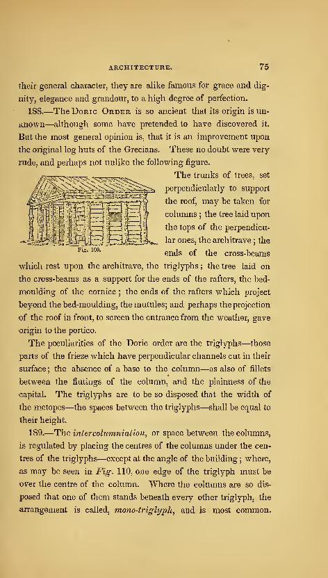
ARCHITECTURE, 75
their general character, they are alike famous for grace and dig-
nity, elegance and grandeur, to a high degree of perfection.
188.—The Doric Order is so ancient that its origin is un-
known—although some have pretended to have discovered it.
But the most general opinion is, that it is an improvement upon
the original log huts of the Grecians. These no doubt were very
rude, and perhaps not unlike the following figure.
The trunks of trees, set
perpendicularly to support
the roof, may be taken for
columns ; the tree laid upon
the tops of the perpendicu-
lar ones, the architrave; the
ends of the cross-beams
which rest upon the architrave, the triglyphs ; the tree laid on
the cross-beams as a support for the ends of the rafters, the bed-
moulding of the cornice ; the ends of the rafters which project
beyond the bed-moulding, the mutules; and perhaps the projection
t)f the roof in front, to screen the entrance from the weather, gave
origin to the portico.
The peculiarities of the Doric order are the triglyphs—those
parts of the frieze which have perpendicular channels cut in their
surface ; the absence of a base to the column—as also of fillets
between the flutings of the column, and the plainness of the
<;apital. The triglyphs are to be so disposed that the width of
the metopes—the spaces between the triglyphs—shall be equal to
their height.
189.—The intercohimniation, or space between the columns,
is regulated by placing the centres of the columns under the cen-
tres of the triglyphs—except at the angle of the building ; where,
as may be seen in Fig. 110, one edge of the triglyph must be
over the centre of the column. Where the columns are so dis-
posed that one of them stands beneath every other triglyph, the
arrangement is called, mono-trig-lyph, and is most common.
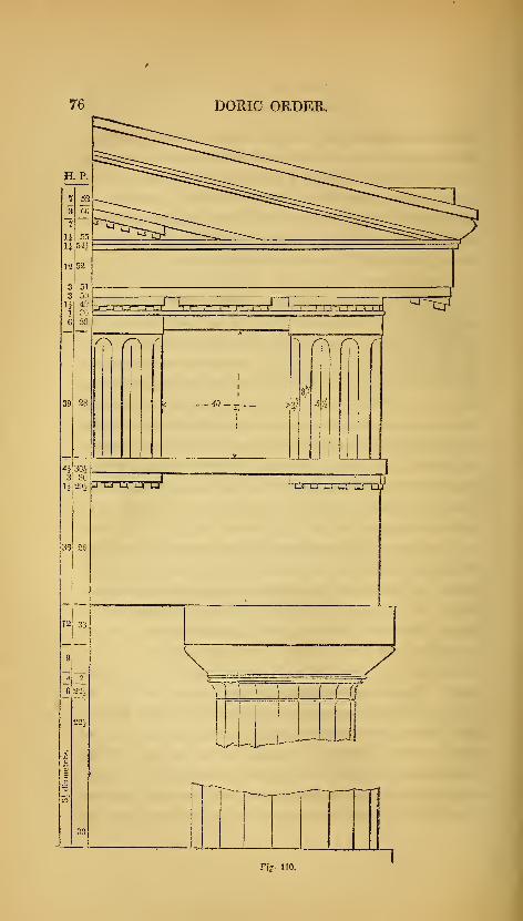
DORIC ORDER.
Fis- no.

ARCHITECTURE. 11
Wlien a column is placed beneath every third triglyph, the ar-
rangement is called diastyle ; and when beneath every fourth,
arcBostyle. This last style is the worst, and is seldom practised.
190.—The Doric order is suitable for buildings that are des-
tined for national purposes, for banking-houses, &c. Its appear-
ance, though massive and grand, is nevertheless rich and grace-
ful. The Custom-House and the Union Bank, in Ne\7-York city,
are good specimens of this order.
191.—The Ionic Order. The Doric was for some time the
only order in use among the Greeks. They gave their attention
to the cultivation of it, until perfection seems to have been at-
tained. Their temples were the principal objects upon v/hich
their skill in the art was displayed ; and as the Doric order seems
to have been well fitted, by its massive proportions, to represent
the character of their male deities rather than the female, there
seems to have been a necessity for another style which should be
emblematical of feminine graces, and. with which they might
decorate such temples as were dedicated to the goddesses. Hence
the origin of the Ionic order. This was invented, according to
historians, by Hermogenes of Alabanda ; and he being a native
of Caria, then in the possession of the lonians, the order was
called, the Ionic.
192.—The distinguishing features of this order are the volutes,
or spirals of the capital ; and the dentils among the bed-mould-
ings of the cornice : although in some instances, dentils are want-
ing. The volutes are said to have been designed as a represen-
tation of curls of hair on the head of a matron, of v/hom the
whole column is taken as a semblance.
193.—The intercolumniation of this and the other orders
—
both Roman and Grecian, with the exception of the Doric—are
distinguished as follows. When the interval is one and a half
diameters, it is called, pyaiostyle, or columns thick-set ; when
two diameters, systyle ; when two and a quarter diameters,
eiistyle ; when three diameters, diastyle ; and when more than
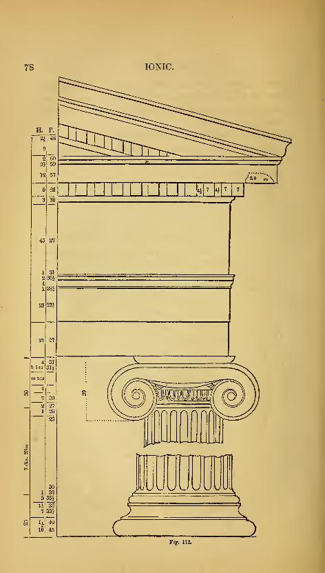
78 IONIC.
Fiff. 111.
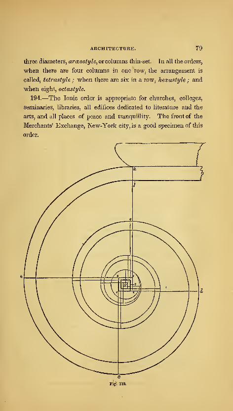
ARCHITECTURE. 79
three diameters, arceosfyle, or columns thin-set. In all the orders,
when there are four columns in one row, the arrangement is
called, tetrastyle ; when there are six in a row, hexastyle ; and
when eight, octastyle.
194.—The Ionic order is appropriate for churches, colleges,
seminaries, libraries, all edifices dedicated to literature and the
arts, and all places of peace and tranquillity. The front of the
Merchants' Exchange, New-York city, is a good specimen of this
order.

80 AMERICAN HOUSE-CARPENTER.
Fig. 113.
195.— To describe the Ionic volute. Draw a perpendicular
from a to s, {Fig. 112,) and make a s equal to 20 min. or to f of
the whole height, a c ; draw 5 o, at right angles to s a, and equal
to li min. ; upon o, with 2| min. for radius, describe the eye of
the volute ; about o, the centre of the eye, draw the square, rt\
2, with sides equal to half the diameter of the eye, viz., 2| min.,
and divide it into 144 equal parts, as shown at Fig. 113. The
several centres in rotation are at the angles formed by the heavy
lines, as figured, 1, 2, 3, 4, 5, 6, &c. The position of these an-
gles is determined by commencing at the point, 1, and making
each heavy line one part less in length than the preceding one.
No. 1 is the centre for the arc, a b, {Fig. 112 ;) 2 is the centre for
the arc, be; and so on to the last. The inside spiral line is to be
described from the centres, x, x, x, &c., {Fig. 113,) being the
centre of the first small square towards the middle of the eye
from the centre for the outside arc. The breadth of the fillet at
aj, is to be made equal to 2-^\ min. This is for a spiral of three
revolutions j but one of any number of revolutions, as 4 or 6,
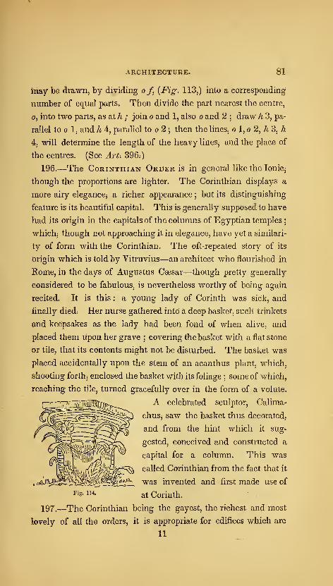
ARCHITECTURE. 81
May he drawn, by dividing of, {Fig. 113,) into a corresponding
number of equal parts. Then divide the part nearest the centre,
o, into two parts, as at h ; join o and 1, also o and 2;draw h 3, pa-
rallel to 1, and h 4, parallel to o 2 ; then the lines, o 1, o 2, A 3, h
4, will determine the length of the heavy lines, and the place of
the centres. (See Art. 396.)
196.—The Corinthian Order is in general like the lonic^
though the proportions are lighter. The Corinthian displays a
more airy eleganccj a richer appearance;but its distinguishing
feature is its beautiful capital. This is generally supposed to have
had its origin in the capitals of the columns of Egyptian temples;
which3 though not approaching it in elegance, have yet a similari-
ty of form with the Corinthian. The oft-repeated story of its
Origin which is told by Yitruvius—an architect who flourished in
Rome, in the days of Augustus Caesar—though pretty generally
considered to be fabulous, is nevertheless worthy of being again
recited. It is this : a young lady of Corinth was sick, and
finally died. Her nurse gathered into a deep basket, sucll trinkets
and keepsakes as the lady had been fond of when alive, and
placed them upon her grave ; covering the basket with a flat stone
Or tile, that its contents might not be disturbed. The basket was
placed accidentally upon the stem of an acanthus plant, which,
Shooting forthj enclosed the basket with its foliage ; some of which,
reaching the tile^ turned gracefully over in the form of a volute.
A celebrated sculptor, Calima-
chus, saw the basket thus decorated,
and from the hint which it sug-
gested, conceived and constructed a
capital for a column. This was
called Corinthian from the fact that it
was invented and first made use of
at Corinth.
197.—The Corinthian being the gayest, the richest and most
lovely of all the orders, it is appropriate for edifices which are
II
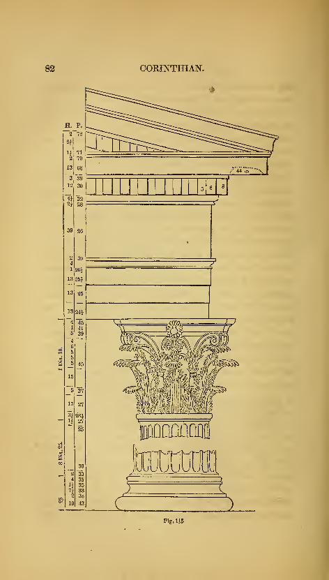
82 CORINTHIAN.
5 8 8
Fig. 115
ARCHITECTURE, 83
dedicated to amusement, banqueting and festivity—for all places
where delicacy, gayety and splendour ^re desirable.
198.—In addition to the three regular orders of architecture, it
was sometimes customary among the Greeks—and afterwards
among other nations—to employ representations of the human
form, instead of columns, to support entablatures ;these were
called Persia7is and Caryatides.
199.
—
Persians are statues of men, and are so called in com-
memoration of a victory gained over the Persians by Pausanias.
The Persian prisoners were brought to Athens and condemned to
abject slavery ; and in order to represent them in the lowest state
of servitude and degradation, the statues were loaded with the
heaviest entablature, the Doric.
200.
—
Caryatides are statues of women dressed in long robes
after the Asiatic manner- Their origin is as follows. In a war
between the Greeks and the Caryans, the latter were totally van-
quished, their male population extinguished, and their females
carried to Athens. To perpetuate the memory of this event,
statues of females, having the form and dress of the Caryans, were
erected, and crowned with the Ionic or Corinthian entablature.
The caryatides were generally formed of about the human size,
but the Persians much larger ; in order to produce the greater awe
and astonishment in the beholder. The entablatures were pro-
portioned to a statue in like manner as to a column of the same
height.
201.—These semblances of slavery have been in frequent use
among moderns as well as ancients ; and as a relief from the
stateliness and formality of the regular orders, are capable of
forming a thousand varieties;yet in a land of liberty such marks
of human degradation ought not to be perpetuated,
202.
—
Roman Styles. Strictly speaking, Rome had no
architecture of her own—all she possessed was borrowed from
other nations. Before the Romans exchanged intercourse with
the Greeks, they possessed some edifices of considerable extent
84 AMERICAN HOUSE-CARPENTER,
9.nd merit, which were erected by architects from Etruria ; but
Rome was principally indebted to Greece for what she acquired
of the art. Although there is no such thing as an architecture of
Roman invention, yet no nation, perhaps, ever was so devoted to
the cultivation of the art as the Roman. Whether we consider
the number and extent of their structures, or the lavish richness
and splendour with which they were adorned, we are compelled
to yield to them our admiration and praise, At one time, under
the consuls and emperors, Rome employed 400 architects. The
public works—such as theatres, circuses, baths, aqueducts, ^c,—
^
were, in extent and grandeur, beyond any thing attempted in
modern times. Aqueducts were built to convey water from a
distance of 60 miles or more. In the prosecution of this work,
rocks and mountains were tunnelled, and valleys bridged. Some
of the latter descended 200 feet below the level of the water ; and
in passing them the canals were supported by an arcade, or sucr
cession of arches. Public baths are spoken of as large as cities
;
being fitted up with numerous conveniences for exercise and
amusement. Their decorations were most splendid ; indeed, the
exuberance of the ornaments alone was offensive to good taste,
So overloaded with enrichments were the baths of Diocletian,
that on an occasion of public festivity, great quantities of sculp^
ture fell from the ceilings and entablatures, killing many of the
people.
203.—The three orders of Greepe were introduced into Romein all the richness and elegance of their perfection. But the luxu-r
rious Romans, not satisfied with the siniple elegance of their re^
fined proportions, sought to improve upon them by lavish displays
of ornament. They transformed in many instances, t\\e true ele^
gance of the Grecian art into a gaudy splendour, better suited to
their less refined taste. The Romans remodelled each of the
orders : the Doric was modified by increasing the height of the
column to 8 diameters; by changing the echinus of the capital
for an ovolo, or quarter-round, and adding an astragal and necl^
ARCHITECTURE, 85
below it 5 by placing the centre of the first triglyph, instead of
one edge, over the centre of the column; and introducing hori-
zontal instead of inclined mutules in the cornice. The Ionic
was modified by diminishing the size of the volutes, and, in some
specimens, introducing a new capital in which the volutes were
diagonally arranged. This new capital has been termed modern
Ionic. The favorite order at Rome and her colonies was the Co-
rinthian. The Roman artists, in their search for novelty, sub-
jected it to many alterations-—especially in the foliage of its capi-
tal. Into the upper part of this, they introduced the modified
Ionic capital ; thus combining the two in one, This change was
dignified with the importance of an order, and received the ap-
pellation Composite, or Roman : the best specimen of which is
found in the Arch of Titus. This style was not much used
among the Romans themselves, and is but slightly appreciated
now. Its decorations are too profuse^—a standing monument of
the luxury of the age in which it was invented.
204.-^The Tuscan Order is said to have been introduced
to the Romans by the Etruscan architects, and to have been
the only style used in Ita'y before the introduction of the
Grecian orders, However this may be, its similarity to the
Doric order gives strong indications of its having been a
rude imitation of that style : this is very probable, since his-
tory informs us that the Etruscans held intercourse with the
Greeks git a remote period. The rudeness of this order prevented
its extensive use in Italy. All that is known concerning it is from
Vitruvius—no remains of buildings in this style being found
iamong ancient ruins.
205. For mills, factories, markets, barns, stables, (fcc, where
utility and strength are of more importance than beauty, the im-
proved modification of this order, called the modern Tuscan,
{Fig. 116,) will be useful ; and its simplicity recommends i|
where economy is desirable.
806,
—
Egyptian Styi^e, The architecture of the ancient
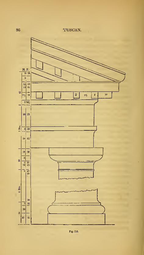
86 TUSCAN.
Fig, 116.

ARCHITECTURE. 87
Egyptians—to which that of the ancient Hindoos bears some re-
semblance—is characterized by boldness of outline, solidity and
grandeur. The amazing labyrinths and extensive artificial lakes,
the splendid palaces and gloomy cemeteries, the gigantic pyramids
and towering obelisks, of the Egyptians, were works of immen-
sity and durability ; and their extensive remains are enduring
proofs of the enlightened skill of this once-powerful, but long since
extinct nation. The principal features of the Egyptian Style of
architecture are—uniformity of plan, never deviating from right
lines and angles ; thick walls, having the outer surface slightly
deviating inwardly from the perpendicular ; the whole building
low ; roof flat, composed of stones reaching in one piece from pier
to pier, these being supported by enormous columns, very short in
proportion to their height ; the shaft sometimes polygonal, having
no base but with a great variety of handsome capitals, the foliage
of these being of the palm, lotus and other leaves ; entablatures
having simply an architrave, crowned with a huge cavetto orna-
mented with sculpture ; and the intercolumniation very narrow,
usually I5 diameters and seldom exceeding 2|. In the remains
of a temple, the walls were found to be 24 feet thick ; and at the
gates of Thebes, the walls at the foundation were 50 feet thick
and perfectly solid. The immense stones of which these, as well
as Egyptian walls generally, were built, had both their inside and
outside surfaces faced, and the joints throughout the body of the
wall as perfectly close as upon the outer surface. For this reason,
as well as that the buildings generally partake of the pyramidal
form, arise their great solidity and durability. The dimensions
and extent of the buildings may be judged from the temple of
Jupiter at Thebes, which was 1400 feet long and 300 feet wide—
•
exclusive of the porticos, of which there was a great number.
It is estimated by Mr. Gliddon, U. S. consul in Egypt, that not
less than 25,000,000 tons of hewn stone were employed in the
erection of the Pyramids of Memphis alone,—or enough to con-
struct 3,000 Bunker-Hill monuments. Some of the blocks are 40
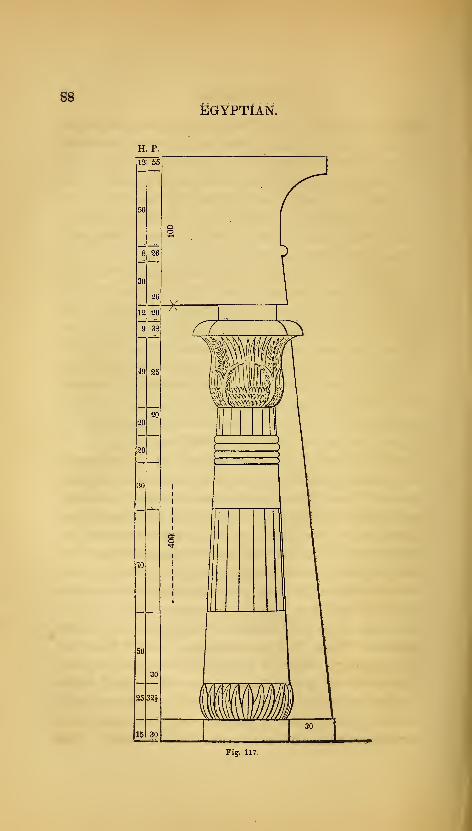
B^Egyptian.
H. p.
Fij. 117.
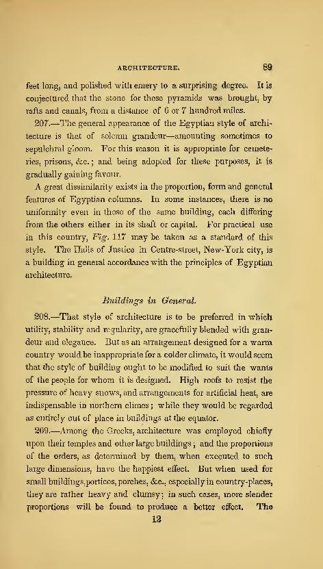
ARCHITECTURE. S3
feet long, and polished with emery to a surprising degree. It is
conjectured that the stone for these pyramids was brought, by
rafts and canals, from a distance of 6 or 7 hundred miles.
207.—The general appearance of the Egyptian style of archi-
lecture is that of solemn grandeur—amounting sometimes to
sepulchral gloom. For this reason it is appropriate for cemete-
ries, prisons, &c. ; and being adopted for these purposes, it is,
gradually gaining favour.
A great dissimilarity exists in the proportion, form and general
features of Egyptian columns. In some instances, there is no
uniformity even in those of the same building, each differing
from the others either in its shaft or capital. For practical use
in this country. Fig. 117 may be taken as a standard of this
style. The Halls of Justice in Centre-street, New-York city, is
a building in general accordance with the principles of Egyptian
architecture.
Buildings in General,
208.—That style of architecture is to be preferred in which
utility, stability and regularity, are gracefully blended with gran-
deur and elegance. But as an arrangement designed for a warm
country would be inappropriate for a colder climate, it would seem
that the style of building ought to be modified to suit the wants
of the people for whom it is designed. High roofs to resist the
pressure of heavy snows, and arrangements for artificial heat, are
indispensable in norlhern climes ; while they would be regarded
as entirely out of place in buildings at the equator.
209.—Among the Greeks, architecture was employed chiefly
upon their temples and other large buildings; and the proportions
of the orders, as determined by them, when executed to such
large dimensions, have the happiest effect. But when used for
small buildings,porticos, porches, &c., especially in country-places,
they are rather heavy and clumsy ; in such cases, more slender
proportions will be found to produce a better effect. The
12
90 AMERICAN HOUSE-CARPENTER.
English cottage-style is rather more appropriate, and is becom-
ing extensively practised for small buildings in the country.
210.—Every building should bear an expression suited to its
destination. If it be intended for national purposes, it should be
magnificent—grand ; for a private residence, neat and modest
;
for a banqueting-house, gay and splendid ; for a monument or
cemetery, gloomy—melancholy ; or, if for a church, majestic and
graceful. By some it has been said—"somewhat dark and
gloomy, as being favourable to a devotional state of feeling ;" but
such impressions can only result from a misapprehension of the
nature of true devotion. " Her ways are ways of pleasantness:,
and all her paths are peace." The church should rather be a type
of that brighter world to which it leads.
211.—However happily the several parts of an edifice may be
disposed, and however pleasing it may appear as a whole, yet
much depends upon its site, as also upon the character and style
of the structures in its immediate vicinity, and the degree of cul-
tivation of the adjacent country. A splendid country-seat should
have the out-houses and fences in the same style with itself, the
trees and shrubbery neatly trimmed, and the grounds well cul-
tivated.
212.—Europeans express surprise that so many houses in this
country are built of wood. And yet, in a new country, where
wood is plenty, that this should be so is no cause for wonder.
Still, the practice should not be encouraged. Buildings erected
with brick or stone are far preferable to those of wood ; they are
more durable; not so liable to injury by fire, nor to need repairs
;
and will be found in the end quite as economical. A wooden
house is suitable for a temporary residence only ; and those whowould bequeath a dwelling to their children,, will endeavour to
build with a more durable material. Wooden cornices and gut-
ters, attached to brick houses, are objectionable—not only on ac-
count of their frail nature, but also because they render the build-
ing liable to destruction by fire.

91
'W
•^ r
d
b
k3
F=? f=?_I 1 F==L^ ^
'<!
\=i—
\,=r F cU 5 r.
Fig. 11& Fig. 119.
yZ AMERICAN HOUSE-CARPENTER.
213.—Dwelling houses are built of various dimensions and
styles, according to their destination ; and to give designs and di-
rections for their erection, it is necessary to know their situation
and object. A dwelling intended for a gardener, would require
very different dimensions and arrangements from one intended for
a retired gentlemen—with his servants, horses, &c. ; nor would
a house designed for the city, be appropriate for the country. For
city houses, arrangements that would be convenient for one fa-
mily, might be very inconvenient for two or more. Fig. 118, 119,
120 and 121, represent the icluiographical projectio?i, or ground-
plan, of the floors of an ordinary city house, designed to be occupied
by one family only. Fig. 122 is an elevation, or front-view, of
the same house : all these plans are drawn at the same scale
—
which is that at the bottom of Fig. 122.
Fig. 118 is a plan of the basement.
a is the dining-room.
b—kitchen.
c—wash-room.
d, d, d,—wash-troughs.
e, e,—pantries with shelving.
/—passage having shelves, drawers, &c., on one side, and
clothes-hooks on the other.
g—kitchen-dresser.
h, i,—front and rear areas.
Fig. 119—plan of the first-story.
k—library.
I—portico.
Fig. 120—plan of the second-story.
a—toilet and sitting room.
b—principal bed-chamber.
c—bath-room.
rfj d,—bed-chambers.
e—^passage with wardrobe and clothes-hooks.
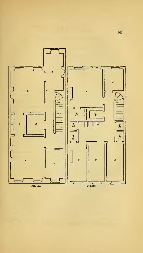
93
J-1
^
zn c.
Hi c
Fig. 120.
Inij^ ^ iTJ L- .1
/
L
i
I
AtA
^? cJ [,, I c-i cL^ c:
Fig. 121.
94 AMERICAN HOUSE-CARPENTER.
Fig. 121—plan of the attic-story.
/-—nursery,
g, g, g: ^—bed-chambers,
h, h, h, h, k,—wardrobes,
i—pantry with shelves,
;—step-ladder leading to roof.
Fig. 122—front elevation.
a—section,
b—front,
These are introduced to give some general ideas of the princi-
ples to be followed in designing city houses. The width of city
lots is ordinarily 25 feet, but as it has become a common practice
to reduce this size, on account of the enhanced value of land, the
plans here given are designed for a lot only 20 feet wide—the or-
dinary width of many buildings of this class. In placing the
chimneys, make the parlours of equal size, and set the chimney-
breast in the middle of the space between the sliding-door parti-
tion and the front (and rear) walls. The basement chimney-
breasts may be placed in the middle of the side of the room, as
there is but one flue to pass through the chimney-breast above
;
but in the second-story, as there is two flues, one from the base-
ment and one from the parlour, the breast will have to be placed
nearly perpendicular over the parlour breast, so as to receive the
flues within the jambs of the fire-place. As it is desirable to
have the chimney-breast as near the middle of the room as pos-
sible, it may be placed a few inches towards that point from over
the breast below. So in arranging those of the stories above,
always make provision for the flues from below.
214.—In placing the stairs, there should be at least as much
room in the passage at the side of the stairs, as upon them ; and in
regard to the length of the passage in the second story, there must
be room for the doors which open from each of the principal rooms
into the hall, and more if the stairs require it. Having assigned
a position for the stairs of the second story, let the winders of
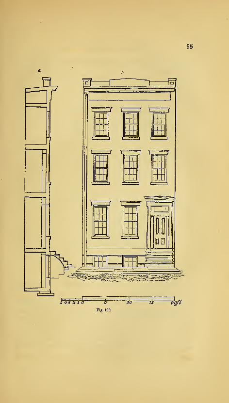
95
1i
', ./ 1, ,
(
"r——
f
[ I r— i t
I 1 1 I t I
?^'^'^:P^^f5j^>:^(n^g^€Ss%^^5^:::-''^''
543 2 10 5 10 15 Sljfi
Fig. 122.
96 AMERICAN HOUSE-CARPENTER.
the other stories be placed perpendicularly over and under them
;
and be careful to provide for head-room. To ascertain this, when
it is doubtful, it is well to draw a vertical section of the whole
stairs ; but in ordinary cases, this is not necessary. To dispose
the windows properly, the middle window of each story should
be exactly in the middle of the front ; but the pier between the
two windows which light the parlour, should be in the centre of
that room ;because when chandeliers or any similar ornaments,
hang from the centre-pieces of the parlour ceilings, it is important,
in order to give the better effect, that the pier-glasses at the front
and rear, be in a range with them. If both these objects cannot
be attained, an approximation to each must be attempted. The
piers should in no case be less in width than the window open-
ings, else the blinds or shutters when thrown open will interfere
with one another ; in general practice, it is well to make the out-
side piers I of the width of one of the middle piers. When this
is desirable, deduct the amount of the three openings from the
width of the front, and the remainder will be the amount of the
width of all the piers ; divide this by 10, and the product will be
i- of a middle pier; and then, if the parlour arrangements do not
interfere, give twice this amount to each corner pier, and three
times the same amount to each of the middle piers.
PRINCIPLES OF ARCHITECTURE.
215.—In the construction of the first habitations of men, frail
and rude as they must have been, the first and principal object
was, doubtless, utility—a mere shelter from sun and rain. But
as successive storms shattered the poor tenement, man was taught
by experience the necessity of building with an idea to durability.
And when in his walks abroad, the symmetry, proportion and
beauty of nature met his admiring gaze, contrasting so strangely
with the misshapen and disproportioned work of his own hands,
he was led to make gradual changes ; till his abode was rendered

ARCHITECTURE. 97
not only commodious and durable, but pleasant in its appearance
;
and building became a fine-art, having utility for its basis.
216.—In all designs for buildings of importance, utility, dura-
bility and beauty, the first great principles of architecture, should
be pre-eminent. In order that the edifice be useful, commodious
and comfortable, the arrangement of the apartments should be
such as to fit them for their several destinations ;for public as-
semblies, oratory, state, visitors, retiring, eating, reading, sleeping,
bathing, dressing, &c.—-^these should each have its own peculiar
form and situation. To accomplish this, and at the same time to
make their relative situation agreeable and pleasant, producing
regularity and harmony, require in some instances much skill and
sound judgment. Convenience and regularity are very import-
ant, and each should have due attention;yet when both cannot
be obtained, the latter should in most cases give place to the for-
mer. A building that is neither convenient nor regular, whatever
other good qualities it may possess, will be sure of disappro-
bation.
217.—The utmost importance should be attached to such ar-
rangements as are calculated to promote health : among these, ven-
tilation is by no means the least. For this purpose, the ceilings of
the apartments should have a respectable height ; and the sky-
light, or any part of the roof that can be made moveable, should
be arranged with cord and pullies, so as to be easily raised and
lowered. Small openings near the ceiling, that may be closed at
pleasure, should be made in the partitions that separate the rooms
from the passages—especially for those rooms which are used for
sleeping apartments. All the apartments should be so arranged
as to secure their being easily kept dry and clean. In dwellings,
suitable apartments should be fitted up for bathing, with all the
necessary apparatus for conveying the water.
218.—To insure stability in an edifice, it should be designed
upon well-known geometrical principles : such as science has de-
monstrated to be necessary and sufficient for firmness and dura-
13
98 AMERICAN HOUSE-CARPENTER.
bility. It is well, also, that it have the appearance of stability as
well as the reality ; for should it seem tottering and unsafe, the
sensation of fear, rather than those of admiration and pleasure,
will be excited in the beholder. To secure certainty and accu-
racy in the application of those principles, a knowledge of the
strength and other properties of the materials used, is indispensa-
ble ; and in order that the whole design be so made as to be
capable of execution, a practical knowledge of the requisite
mechanical operations is quite important.
219.—The elegance of an architectural design, although chiefly
depending upon a just proportion and harmony of the parts, will
be promoted by the introduction of ornaments—provided this be
judiciously performed. For enrichments should not only be of a
proper character to suit the style of the building, but should also
have their true position, and be bestowed in proper quantity. The
most common fault, and one which is prominent in Roman archi-
tecture, is an excess of enrichment : an error which is carefully
to be guarded against. But those who take the Grecian models
for their standard, will not be liable to go to that extreme. In
ornamenting a cornice, or any other assemblage of mouldings, at
least every alternate member should be left plain ; and those that
are near the eye should be more finished than those whichf are dis-
tant. Although the characteristics of good architecture are utili-
ty and elegance, in connection with durability, yet some buildings
are designed expressly for use, and others again for ornament : in
the former, utility, and in the latter, beauty, should be the gov-
erning principle.
220.—The builder should be intimately acquainted with the
principles upon which the essential, elementary parts of a build-
ing are founded. A scientific knowledge of these will insure
certainty and security, and enable the mechanic to erect the most
extensive and lofty edifices with confidence. The more important
parts are the foundation, the column, the wall, the lintel, the arch,
the vault, the dome and the roof. A separate description of the

ARCHITECTURE. 99
peculiarities of each, would seem to be necessary ; and cannot
perhaps be better expressed than in the following language of a
modern writer on this subject.
221.—"In laying the Foundation of any building, it is ne-
cessary to dig to a certain depth in the earth, to secure a solid
basis, below the reach of frost and common accidents. The
most solid basis is rock, or gravel which has not been moved.
Next to these are clay and sand, provided no other excavations
have been made in the immediate neighbourhood. From this
basis a stone wall is carried up to the surfiice of the ground, and
constitutes the foundation. Where it is intended that the super-
structure shall press unequally, as at its piers, chimneys, or
columns, it is sometimes of use to occupy the space between the
points of pressure by an inverted arch. This distributes the
pressure equally, and prevents the foundation from springing be-
tween the different points. In loose or muddy situations, it is
always unsafe to build, unless we can reach the solid bottom
below. In salt marshes and flats, this is done by depositing tim-
bers, or driving wooden piles into the earth, and raising walls
upon them. The preservative quality of the salt will keep these
timbers unimpaired for a great length of time, and makes the
foundation equally secure with one of brick or stone.
222.—The simplest member in any building, though by no
means an essential one to all, is the Column, or pillar. This is
a perpendicular part, commonly of equal breadth and thickness,
not intended for the purpose of enclosure, but simply for the sup-
port of some part of the superstructure. The principal force
which a column has to resist, is that of perpendicular pressure.
In its shape, the shaft of a column should not be exactly cylin-
drical, but, since the lower part must support the weight of the
superior part, in addition to the weight which presses equally on
the whole column, the thickness should gradually decrease from
bottom to top. The outline of columns should be a little curved,
spas to represent a portion of a very long spheroid, or paraboloid,

lOO AMERICAN HOUSE-CARPENTER.
rather than of a cone. This figure is the joint result of two cal-
culations, independent of beauty of appearance. One of these
is, that the form best adapted for stability of base is that of a
cone; the other is, that the figure, which would be of equal
strength throughout for supporting a superincumbent weight,
would be generated by the revolution of two parabolas round the
axis of the column, the vertices of the curves being at its ex-
tremities. The swell of the shafts of columns Avas called the en-
tasis by the ancients. It has been lately found, that the columns
of the Parthenon, at Athens, which have been commonly sup-
posed straight, deviate about an inch from a straight line, and
that their greatest swell is at about one third of their height.
Columns in the antique orders are usually made to diminish one
sixth or one seventh of their diameter, and sometimes even one
fourth. The Gothic pillar is commonly of equal thickness
throughout.
223.—The Wall, another elementary part of a building, may
be considered as the lateral continuation of the column, answer-
ing the purpose both of enclosure and support. A wall must
diminish as it rises, for the same reasons, and in the same propor-
tion, as the column. It must diminish still more rapidly if it ex-
tends through several stories, supporting weights at diflerent
heights. A wall^ to possess the greatest strength, must also con-
sist of pieces, the upper and lower surfaces of which are horizon-
tal and regular, not rounded nor oblique. The walls of most of
the ancient structures which have stood to the present time, are
constructed in this manner, and frequently have their stones bound
together with bolts and cramps of iron. The same method is
adopted in such modern structures as are intended to possess great
strength and durability, and, in some cases, the stones are even
dove-tailed together, as in the light-houses at Eddystone and Bell
Kock. But many of our modern stone walls, for the sake of
cheapness, have only one face of the stones squared, the inner
half of the wall being completed with brick ; so that they can,
ARCHITECTURE. 101
in reality, be considered only as brick walls faced with stone.
Such walls are said to be liable to become convex outwardly, from
the difference in the shrinking of the cement. Rubble walls are
made of rough, irregular stones, laid in mortar. The stones
should be broken, if possible, so as to produce horizontal surfaces.
The coffer walls of the ancient Romans were made by enclosing
successive portions of the intended wall in a box, and filling it
with stones, sand, and mortar, promiscuously. This kind of
structure must have been extremely insecure. The Pantheon,
and various other Roman buildings, are surrounded with a double
brick wall, having its vacancy filled up with loose bricks and
cement. The whole has gradually consolidated into a mass of
great firmness.
The reticulated walls of the Romans, having bricks with
oblique surfaces, would, at the present day, be thought highly
unphilosophical. Indeed, they could not long have stood, had it
not been for the great strength of their cement. Modern brick
walls are laid with great precision, and depend for firmness more
upon their position than upon the strength of their cement. The
bricks being laid in horizontal courses, and continually overlaying
each other, or breaking joints^ the whole mass is strongly inter-
woven, and bound together. Wooden walls, composed of timbers
covered with boards, are a common, but more perishable kind.
They require to be constantly covered with a coating of a foreign
substance, as paint or plaster, to preserve them from spontaneous
decomposition. In some parts of France, and elsewhere, a kind
of wall is made of earth, rendered compact by ramming it in
moulds or cases. This method is called building in pise, and is
much more durable than the nature of the material would lead
us to suppose. Walls of all kinds are greatly strengthened by
angles and curves, also by projections, such as pilasters, chimneys
and buttresses. These projections serve to increase the breadth
of the foundation, and are always to be made use of in large
buildings, and in walls of considerable length.
102 AMERICAN HOUSE-CARtENTER.
224.—The Lintel, or beam, extends in a right line over a
vacant space, from one column or wall to another. The strength
of the lintel will be greater in proportion as its transverse vertical
diameter exceeds the horizontal, the strength being always as the
square of the depth. The floor is the lateral continuation or
connection of beams by means of a covering of boards.
225.—The Arch is a transverse member of a building, an-
swering the same purpose as the lintel, but vastly exceeding it in
strength. The arch, unlike the lintel, may consist of any num-
ber of constituent pieces, without impairing its strength. It is,
however, necessary that all the pieces should possess a uniform
shape,—the shape of a portion of a wedge,—and that the joints,
formed by the contact of their surfaces, should point towards a
common centre. In this case, no one portion of the arch can be
displaced or forced inward ; and the arch cannot be broken by
any force which is not sufficient to crush the materials of which
it is made. In arches made of common bricks, the sides of which
are parallel, any one of the bricks might be forced inward, were
it not for the adhesion of the cement. Any two of the bricks,
however, by the disposition of their mortar, cannot collective-
ly be forced inward. An arch of the proper form, when com-
plete, is rendered stronger, instead of weaker, by the pressure of
a considerable weight, provided this pressure be uniform. While
building, however, it requires to be supported by a centring of
the shape of its internal surface, until it is complete. The upper
stone of an arch is called the key-stone^ but is not more essential
than any other. In regard to the shape of the arch, its most
simple form is that of the semi-circle. It is, however, very fre-
quently a smaller arc of a circle, and, still more frequently, a por-
tion of an ellipse. The simplest theory of an arch supporting
itself only, is that of Dr. Hooke, The arch, when it has only
its own weight to bear, may be considered as the inversion of a
chain, suspended at each end. The chain hangs in such a form,
that the weight of each link or portion is held in equilibrium by
ARCHITECTURE. 103
the result of two forces acting at its extremities ; and these forces,
or tensions, are produced, the one by the weight of the portion of
the chain below the link, the other by the same weight increased
by that of the link itself, both of them acting originally in a ver-
tical direction. Now, supposing the chain inverted, so as to con-
stitute an arch of the same form and weight, the relative situa-
tions of the forces will be the same, only they will act in contrary
directions, so that they are compounded in a similar manner, and
balance each other on the same conditions.
The arch thus formed is denominated a catenary arch. In
common cases, it differs but little from a circular arch of the extent
of about one third of a whole circle, and rising from the abut-
ments with an obliquity of about 30 degrees from a perpendicu-
lar. But though the catenary arch is the best form for support-
ing its own weight, and also all additional weight which presses
in a vertical direction, it is not the best form to resist lateral
pressure, or pressure like that of fluids, acting equally in all direc-
tions. Thus the arches of bridges and similar structures, when
covered with loose stones and earth, are pressed sideways, as well
as vertically, in the same manner as if they supported a weight
of fluid. In this case, it is necessary that the arch should arise
more perpendicularly from the abutment, and that its general
figure should be that of the longitudinal segment of an ellipse.
In small arches, in common buildings, where the disturbing
force is not great, it is of little consequence what is the shape of
the curve. The outlines may even be perfectly straight, as in the
tier of bricks which we frequently see over a window. This is,
strictly speaking, a real arch, provided the surfaces of the bricks
tend towards a common centre. It is the weakest kind of arch,
and a part of it is necessarily superfluous, since no greater portion
can act in supporting a weight above it, than can be included be-
tween two curved or arched lines.
Besides the arches already mentioned, various others are in use.
The acute or lancet arch, much used in Gothic architecture, is
104 AMERICAN HOUSE-CARPENTER.
described usually from two centres outside the arch. It is a
strong arch for supporting vertical pressure. The rampant arch
is one in which the two ends spring from unequal heights. The
horse-shoe or Moorish arch is described from one or more centres
placed above the base line. In this arch, the lower parts are in
danger of being forced inward. The ogee arch is concavo-con-
vex, and therefore fit only for ornament. In describing arches,
the upper surface is called the extrados, and the inner, the in-
trados. The springing lines are those where the intrados meets
the abutments, or supporting walls. The span is the distance
from one springing line to the other. The wedge-shaped stones,
which form an arch, are sometimes cdXledi .voussoirs, the upper-
most being the key-stone. The part of a pier from which an
arch springs is called the impost, and the curve formed by the
upper side of the voussoirs, the archivolt. It is necessary that
the walls, abutments and piers, on which arches are supported,
should be so firm as to resist the lateral thrust, as well as vertical
pressure, of the arch. It will at once be seen, that the lateral or
sideway pressure of an arch is very considerable, when we recol-
lect that every stone, or portion of the arch, is a wedge, a part of
whose force acts to separate the abutments. For want of atten-
tion to this circumstance, important mistakes have been committed,
the strength of buildings materially impaired, and their ruin ac-
celerated. In some cases, the want of lateral firmness in the
walls is compensated by a bar of iron stretched across the span of
the arch, and connecting the abutments, like the tie-beam of a
roof. This is the case in the cathedral of Milan and some other
Gothic buildings.
In an arcade, or continuation of arches, it is only necessary that
the outer supports of the terminal arches should be strong enough
to resist horizontal pressure. In the intermediate arches, the lat-
eral force of each arch is counteracted by the opposing lateral
force of the one contiguous to it. In bridges, however, where
individual arches are liable to be destroyed by accident, it is desi-

ARCHITECTURE. 106
i'able that each of the piers should possess sufficient horizontal
strength to resist the lateral pressure of the adjoining arches.
226.—The Vault is the lateral continuation of an arch, serving
to cover an area or passage, and bearing the same relation to the
arch that the wall does to the column. A simple vault is con-
structed on the principles of the arch, and distributes its pressure
equally along the walls or abutments. A complex or groined
vault is made by two vaults intersecting each other^ in which
base the pressure is thrown upon springing points, and is greatly-
increased at those points* The groined vault is common in
Gothic architecture,
227.—The Dome, sbnietimes called cupola, is a concave cover-
ing to a building, or part of itj and may be either a segment of a
sphere, of a spheroid, or of any similar figure. When built of
stone, it is a very strong kind of structure, even more so than the
arch, since the tendency of each part to fall is counteracted, not
bnly by those above and below it, but also by those on each sidej
It is only necessary that the constituent pieces should have St
bommon form, and that this form should be somewhat like the
frustum of a pyramid, so that, when placed in its situation^ its
four angles may point toward the centre, of axis, of the dome.
During the erection of a dome^ it is not necessary that it should
be supported by a centring, until complete, as is done in the arch.
Each circle of stones, when laidj is capable of supporting itself
without aid from those above it. It follows that the dome may
be left open at top, without a key-stone, and yet be perfectly
isecure in this respect, being the reverse of the arch. The dome
of the Pantheon, at Rome, has been always open at top, and yet
has stood unimpaired for nearly 2000 years. The upper circle
bf stones, though apparently the weakest, is nevertheless often
tnade to support the additional weight of a lantern or tower above
it. In several of the largest cathedrals, there are two domes, one
\vithin the other, which contribute their joint support to the lan-
tern, which rests upon the top. In these buildings, the dome
14
106 AMERICAN HOUSE-CARPENTER.
rests upon a circular wall, which is supported, in its turn, by
arches upon massive pillars or piers, '^his construction is called
building upon pendentives, and gives open space and lOom for
passage beneath the dome. The remarks which have been made
in regard to the abutments of the arch, apply equally to the walls
immediately supporting a dome. They must be of sufficient
thickness and solidity to resist the lateral pressure of the dome,
which is very great. The wails of the Roman Pantheon are of
great depth and solidity. In order that a dome in itself should be
perfectly secure, its lower parts must not be too nearly vertical,
since, in this case, they partake of the nature of perpendicular
walls, and are acted upon by the spreading force of the parts above
them. The dome of St. Paul's church, in London, and some
others of similar construction, are bound with chains or hoops of
iron, to prevent them from spreading at bottom. Domes which
are made of wood depend, -in part, for their strength, on their in-
ternal carpentry. The Halle du Bled, in Paris, had originally a
wooden dome more than 200 feet in diameter, and only one foot
in thickness. This has since been replaced by a dome of iron.
(See Art. 303.)
228.—The Roof is the most common and cheap method of
covering buildings, to protect them from rain and other effects of
the weather. It is sometimes flat, but more frequently oblique, in
its shap-e. The flat or platform-roof is the least advantageous for
shedding rain, and is seldom used in northern countries. The
pent roof, consisting of two oblique sides meeting at top, is the
most common form. These roofs are made steepest in cold cli-
mates, where they are liable to be loaded with snow. Where the
four sides of the roof are all oblique, it is denominated a hipped
roof, and where there are two portions to the roof, of different ob-
liquity, it is a curb, or mansard roof. In modern times, roofs
are made almost exclusively of wood, though frequently covered
with incombustible materials. The internal structure or carpen-
try of rpofs is a subject of considerable mechanical contrivance.
ARCHITECTURE. 107
The roof is supported by rafters, which abut on the walls on
each side, like the extremities of an arch. If no other timbers
existed, except the rafters, they would exert a strong lateral pres-
sure on the walls, tending to separate and overthrow them. To
counteract this lateral force, a tie-beam, as it is called, extends
across, receiving the ends of the rafters, and protecting the wall
from their horizontal thrust. To prevent the tie-beam from
sagging, or bending downward with its own weight, a king-
post is erected from this beam, to the upper angle of the rafters,
serving to connect the whole, and to suspend the weight of the
beam. This is called trussing. Queen-posts are sometimes
added, parallel to the king-post, in large roofs ; also various other
connecting timbers. In Gothic buildings, where the vaults do
not admit of the use of a tie-beam, the rafters are prevented from
spreading, as in an arch, by the strength of the buttresses.
In comparing the lateral pressure of a high roof with that of a
low one, the length of the tie-beam being the same, it will be
seen that a high roof, from its containing most materials, may
produce the greatest pressure, as far as weight is concerned. On
the other hand, if the weight of both be equal, then the low roof
will exert the greater pressure ; and this will increase in propor-
tion to the distance of the point at which perpendiculars, drawn
from the end of each rafter, would meet. In roofs, as well as in
wooden domes and bridges, the materials are subjected to an in-
ternal strain, to resist which, the cohesive strength of the material
is relied on. On this account, beams should, when possible, be
of one piece. Where this cannot be effected, two or more beams
are connected together by sjilicing. Spliced beams are never so
strong as whole ones, yet they may be made to approach the same
strength, by affixing lateral pieces, or by making the ends overlay
each other, and connecting them with bolts and straps of iron.
The tendency to separate is also resisted, by letting the two pieces
into each other by the process called scarfing. Mortices, in-
108 AMERICAN HOUSE-CARPENTER.
tended to truss or suspend one piece by another, should be formed
upon similar principles,
Roofs in the United States, after being boarded, receive a ser
condary covering of shingles, When intended tobe incombustible,
they are covered with slates or earthern tiles, or with sheets of lead,
copper or tinned iron. Slates are preferable to tiles, being lighter,
and absorbing less moisture. Metallic sheets are chiefly used for
flat roofs, wooden domes, and curved and angular surfaces, which
require a flexible material to cover them, or have not a sufiicient
pitch to shed the rain from slates or shingles. Yarious artificial
compositions are occasionally used to cover roofs, the most com-
mon of which are mixtures of tar with lime, and sometimes witlpi
sand and gravel."
—
Enoy. Am. (See Art. 285.)
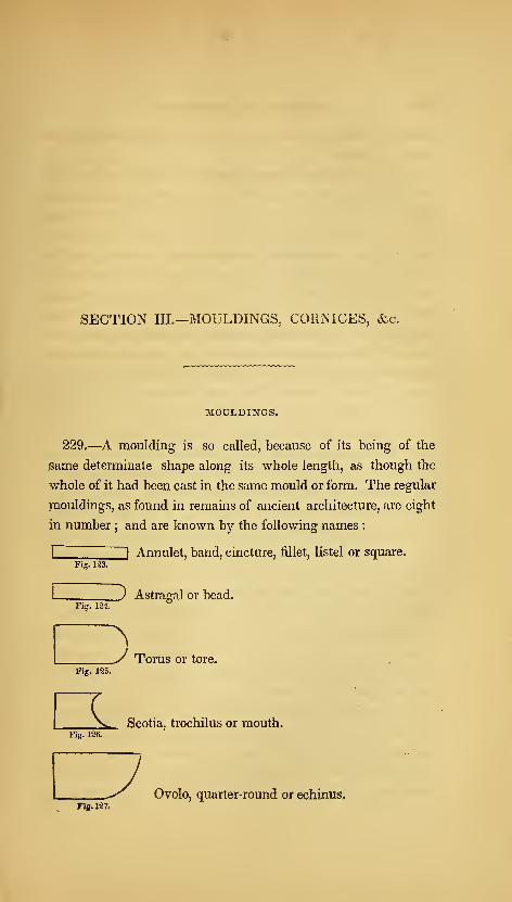
iSECTION III.—MOULDINGS, CORNICES, &c.
MOULDINGS.
229.—A moulding is so called, because of its being of the
same determinate shape along its whole length, as though the
whole of it had been cast in the same mould or form. The regular
mouldings, as found in remains of ancient architecture, are eight
in number ; and are known by the following names :
I i Annulet, band, cincture, fillet, listel or square.
Fi?. 124.
__) Astragal or bead.
_V Torus or tore.Fig. 125.
Fig. 126.
L Scotia, trochilus or mouth.
Ovolo, quarter-round or echinus.Fi«. 127,

110 AMERICAN HOUSE-CARPENTER.
Fig. 129.
CavettOj cove or hollow.
Cymatiunij or cyma-recta.
I
JFig. 130.
J ^ Ogee.
Inverted cymatium, or cyma-reversa. )
Some of the terms are derived thus : fillet, from the French
word^Z, thread. Astragal, from astragalos, a bone of the heel
—or the curvature of the heel. Bead, because this moulding,
when properly carved, resembles a string of beads. Torus, or
tore, the Greek for rope, which it resembles, when on the base of
a column. Scotia, from shotia, darkness, because of the strong
shadow which its depth produces, and which is increased by the
projection of the torus above it. Ovolo, from ovum., an egg,
which this member resembles, when carved, as in the Ionic capi-
tal. Cavetto, from cavus, hollow. Cymatium, from kumaton,
a wave.
230.—Neither of these mouldings is peculiar to any one of the
orders of architecture, but each one is common to all; and al-
though each has its appropriate use, yet it is by no means con-
fined to any certain position in an assemblage of mouldings.
The use of the fillet is to bind the parts, as also that of the astra-
gal and torus, which resemble ropes. The ovolo and cyma-re-
versa are strong at their upper extremities, and are therefore used
to support projecting parts above them. The cyma-recta and
cavetto, being weak at their upper extremities, are not used as
supporters, but are placed uppermost to cover and shelter the
other parts. The scotia is introduced in the base of a column, to
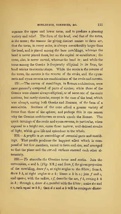
MOULDINGS, CORNICES, &C. Ill
separate the upper and lower torus, and to produce a pleasing
variety and relief. The form of the bead, and that of the torus,
is the same ; the reasons for givin'g distinct names to them are,
that the torus, in every order, is always considerably larger than
the bead, and is placed among the base mouldings, whereas the
bead is never placed there, but on the capital or entablature ; the
torus, also, is never carved, whereas the bead is ; and while the
torus among ,the Greeks is frequently elliptical in its form, the
bead retains its circular shape. While the scotia is the reverse of
the torus, the cavetto is the reverse of the ovolo, and the cyma-
recta and cyma-reversa are combinations of the ovolo and cavetto.
23 i.—The curves of mouldings, in Roman architecture, were
most generally composed of parts of circles ; while those of the
Greeks were almost always elliptical, or of some one of the conic
sections, but rarely circular, except in the case of the bead, which
was always, among both Greeks and Romans, of the form of a
semi-circle. Sections of the cone afford a greater variety of
forms than those of the sphere ; and perhaps this is one reason
why the Grecian architecture so much excels the Roman. The
quick turnings of the ovolo and cyma-reversa, in particular, when
exposed to a bright sun, cause those narrow, well-defined streaks
of light, which give life and splendour to the whole.
232.
—
K profile is an assemblage of essential parts and mould-
ings. That profile produces the happiest effect which is com-
posed of but few members, varied in form and size, and arranged
so that the plane and the curved surfaces succeed each other al-
ternately,
233.— To describe tke Greciafi torus and scotia. Join the
extremities, a and b, {Fig. 131;) and from/, the given projection
of the moulding, draw/ o, at right angles to the fillets ; from b,
draw b h, at right angles to a b ; bisect a b in c ; join / and c,
and upon c, with the radius, c/ describe the arc, / h, cutting b h
in h ; through c, draw d e, parallel with the fillets; make d c and
c e, each equal to b h ; then d e and a b will be conjugate diame-
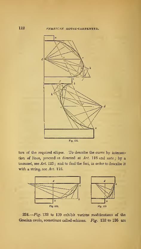
112 AMERICAN HOUSE-CARPENTER.
ters of the required ellipse. To describe the curve by interset--
tion of lines, proceed as directed at Art. 118 and noie ; by a
trammel, see Art^ 125 ;and to find the foci, in order to describe it
with a string, see Art. 115.
Fig. 132.
d
\a
Fig-. 133
23L—Fig. 132 to 139 exhibit various modifications of the
Grecian ovolo, sometimes called echinus. Fig. 132 to 136 are
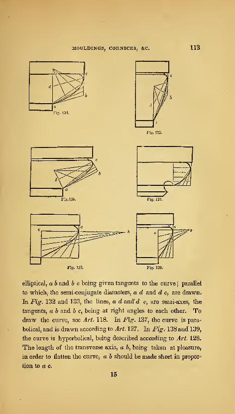
MOULDINGS, CORNICES, &C. 113
Fi:r. 134.
,»'"••.
' ^L—
^
Fig. 136. Fig. 137.
c N a
::^
A5=^-
^
a«
c
^^
Fig. 13&. Fig. 139^
elliptical, a h and h c being given tangents to the curve;parallel
to which, the semi-conjugate diameters, a d and d Cj are draAVn.^
In Fig. 132 and 133, the lines, a d and'c? c, are semi^axes, the
tangents, a b and b c, being at right angles to each other. Todraw the curve, see Art. 118. In Fig. 137, the curve is para^
bolical, and is drawn according to Art. 127. In Fig, 138 and 139,
the curve is hyperbolical, being described according to Art. 128.
The length of the transverse axis, a b, being taken at pleasure,
in order to flatten the curve, a b should be made short in propor-
tion to a c.
IS
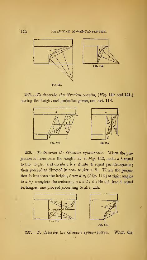
114 AMERICAN HOUSE-CARPENTER.
Fig. 141.
Fig. 140.
235.— To describe the Grecian cavetto^ {Fig. 140 and 141,)
having the height and projection given, see Art. 118.
a
\M1IJ^fiV c
Fi?. 142. Fig. 143.
236.— To describe the Grecian cyma-recta. When the pro-
jection is more than the height, as at Fig. 142, make a h equal
to the height, and divide abed into 4 equal parallelograms
;
then proceed as directed in note to Art. 118. When the projec-
tion is less than the height, draw d a, [Fig. 143,) at right angles
to a b ; complete the rectangle, abed; divide this into 4 equal
rectangles, and proceed according to Art. 118,
237.—To describe the Grecian cyma-reversa. When the

MOULDINGS, CORNICES, &C. 115
projection is more than the height, as at Fig. 144, proceed as di-
rected for the last figure;the curve being the same as that, the
position only being changed. When the projection is less than
the height, draw a d, {Fig. 145,) ^.t right angles to the fillet
;
make a d equal to the projection of the moulding : then proceed
as directed for Fig. 142.
238.—^Roman mouldings are composed of parts of circles, and
have, therefore, less beauty of form than the Grecian. The bead
and torus are of the form of the semi-circle, and the scotia, also,
in some instances ; but the latter is often composed of two quad-
rants, having difierent radii, as at Fig. 146 and 147, which re-
semble the elliptical curve. The ovolo and cavetto are generally
a quadrant, but often less. When they are less, as at Fig. 150,
the centre is found thus : join the extremities, a and 6, and bisect
ahm. c ; from c, and at right angles to a b, draw c d, cutting a
level line drawn from a in d ; then d v/ill be the centre. This
moulding projects less than its height. When the projection is
more than the height, as at Fig. 152, extend the line from c until
Fjg., 146.
Fig. 148, Fig. 149,
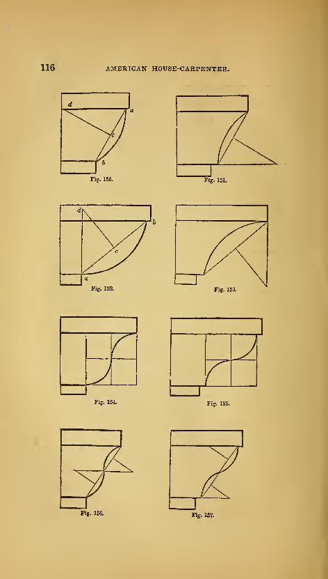
116 AMERICAN HOUSE-CARPENTER.
Fig. 150. Fig. 151.
WaFig. 152, Fig, 153.
Fig, 154, Fig, 155,
Fig. 156. Fig. 1«.

MOULDINGS, CORNICES, &C 117
Fig. 158. Fig. 159.
Fig. 160.
it cuts a perpendicular drawn from a, as at d; and that will bathe
centre of the curve. In a similar manner, the centres are found
for the mouldings 3X Fig. 147, 151, 153, 1.56, 157, 158 and 159.
The centres for the curves at Fig. 160 and 161, are found thus :
bisect the line, a b, at c ; upon a, c and b, successively, with a c
or c 6 for radius, describe arcs intersecting at d and d ; then those
intersections will be the centres.
239.
—
Fig. 162 to 169 represent mouldings of modern inven-
tion. They have been quite extensively and successfully used in
inside finishing. Fig. 162 is appropriate for a bed-moulding
under a low, projecting shelf, and is frequently used under man-
tle-shelves. The tangent, i h, is found thus : bisect the line, a b,
at c, and b c aX d; from d, draw d e, at right angles to e 6 ; from
6j draw b f, parallel to e d ; upon b, with b d for radius, describe
the arc, df; divide this arc into 7 equal parts, and set one of the
parts from s, the limit of the projection, to o ; make o h equal to
e ; from h, through c, draw the tangent, h i; divide b h, h c, ci
and i a, each into a like number of equal parts, and draw the in-

118 AMERICAN HOUSE-CARPENTER.
Fig. 163.
Fig. 164.
^>—^flrwi,^^^
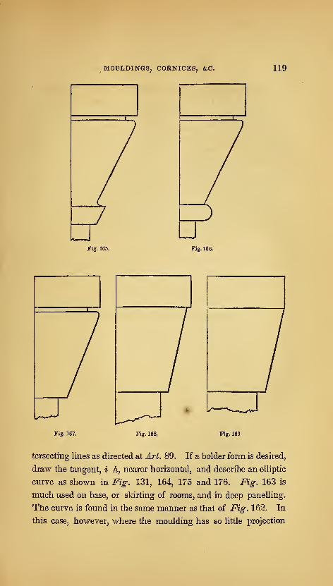
MOULDINGS, CORNICES, &C 119
Fig. 165. Fig. 166.
Fig. 167. Fig. 168, Fig. 169
tersecting lines as directed at Art. 89. If a bolder form is desired,
draw the tangent, i h, nearer horizontal, and describe an elliptic
curve as shown in Fig: 131, 164, 175 and 176. Fig. 163 is
much used on base, or skirting of rooms, and in deep panelling.
The curve is found in the same manner as that of Fig. 162. In
this case, however, where the moulding has so little projection

120 AMERICAN HOUSE-CARPENTER.
in comparison with its height, the point, e, being found as in the
last figure, h s may be made equal to s e, instead of o e as in the
last figure. Fig: 164 is appropriate for a crown moulding of a
cornice. In this figure the height and projection are given ; the
direction of the diameter, a b, drawn through the middle of
the diagonal, e /, is taken at pleasure ; and d cis parallel to a
e. To find the length of d c, draw b A, at right angles to a b ;
upon 0, with o f for radius, describe the arc,/ /i, cutting bh in
h ; then make o c and o d, each equal to b h* To draw the curve,
see note to Art. 118. Fig. 165 to 169 are peculiarly distinct from
ancient mouldings, being composed principally of straight lines;
the few curves they possess are quite short and quick.
H. P.H. P.
5 15
4
12}
a 11 1
9 10}
10
14}
Hi
111-
10}
Fig. 170. Fig. 171.
240.—F^^. 170 and 171 are designs for antae caps. The
* The manner of ascertaining the length of the conjugate diameter, d c, in this figure,
and also in Fig. 131, 175 and 176, is new, and is important in this application. It is
founded upon well-known mathematical principles, viz: All the parallelograms that may
be circumscribed about an ellipsis are equal to one another, and consequently any one
is equal to the rectangle of the two axes. And again : the sum of the squares of every
pair of conjugate diameters is equal to the sum of the squares of the two axes.
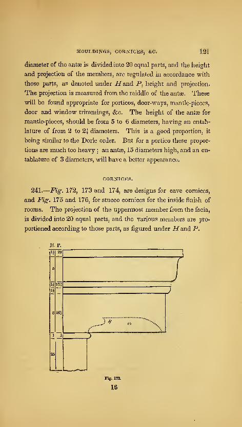
MouLOiNGfgj Cornices, &c. 121
diameter of the antse is divided into 20 equal parts, and the height
and projection of the members, are regulated in accordance with
those parts, as denoted under H and P, height and projection-
The projection is measured from the middle of the antse. These
will be found appropriate for porticos^ door-ways, mantle-pieces,
door and window trimmingSj &c. The height of the antas for
mantle-pieces, should be from 5 to 6 diameters j having an entab-
lature of from 2 to 2i diameters. This is a good proportion, it
being similar to the Doric order. But for a portico these propor-
tions are much too heavy ; an antee, 15 diameters high, and an en-
tablature of 3 diametersj will have a better appearance.
CORNICES.
241.
—
Fig. 172, 173 and 174, are designs for eave corniceSj
and Fig. 175 and 176j for stucco cornices for the inside finish of
rooms. The projection of the uppermost member from the facia,
is divided into 20 equal parts, and the various members are pro-
portioned according to those parts, as figured under Hand P.
H. P.
U 20
17i
25
mJ^
Tig. 172,
18
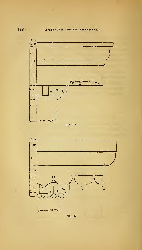
122 AMERICAN HOUSE-CARPENTER.
H. P.
riiso
a
3kM
25
H. P.
>'44
H 2i 2}
Fig. 173.
Fig. 174.

MOULDINGS, CORNICES, &C. 123
Fig. 176.
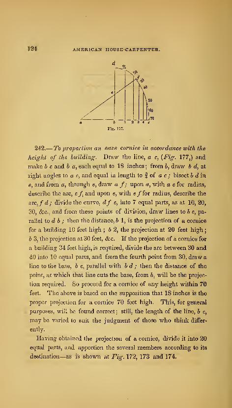
124 AMERICAN HOUSE-CARPENTER,
d
h 12 3 4cFig. nt.
242.— To propori'w7i an save cor?iice in accordance with the
height of the building. Draw the line, a c, {Fig. 177,) and
make b c and b or, each equal to 18 inches ; from b, draw b d, at
right angles to a c, and equal in length to | of a c ; bisect b din
e, and from a, through e, draw a f; upon a, with a c for radius,
describe the arc, c/, and upon e, with e/for radius, describe the
arc,/c?; divide the curve, df c, into 7 equal parts, as at 10, 20,
30, &c., and from these points of division, draw lines to b c, pa^
rallel to d b ; then the distance, b 1, is the projection of a cornice
for a building 10 feet high ; b 2, the projection at 20 feet high
;
b 3, the projection at 30 feet, &c. If the projection of a cornice for
a building 34 feet high, is required, divide the arc between 30 and
40 into 10 equal parts, and from the fourth point from 30, draw a
line to the base, b c, parallel with b d ; then the distance of the
point, at which that line cuts the base, from b, will be the projec-
tion required. So proceed for a cornice of any height within 70
feet. The above is based on the supposition that 18 inches is the
proper projection for a cornice 70 feet high. This, for general
purposes, will be found correct ; still, the length of the line, b c,
may be varied to suit the judgment of those who think differ-
ently.
Having obtained the projection of a cornice, divide it into 20
equal parts, and apportion the several members according to its
destination—as is shown at Fig. 172, 173 and 174,
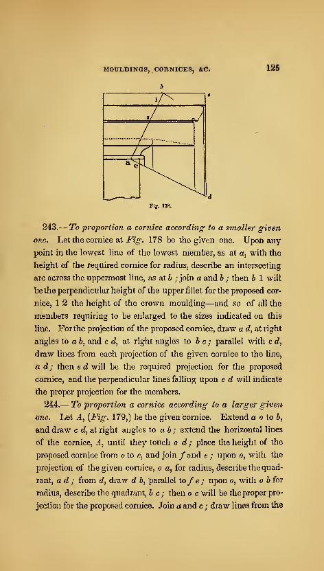
MOULDINGS, CORNICES, &C.
b
125
Fig. 178.
243.— To proportion a cornice according to a smaller given
one. Let the cornice at Fig. 178 be the given one. Upon any
point in the lowest line of the lowest member, as at a, with the
height of the required cornice for radius, describe an intersecting
arc across the uppermost line, as at b ; join a and b ; then b 1 will
be the perpendicular height of the upper jfillet for the proposed cor-
nice, 1 2 the height of the crown moulding—and so of all the
members requiring to be enlarged to the sizes indicated on this
line. For the projection of the proposed cornice, draw a d, at right
angles to a b, and c d, at right angles to be; parallel with c d,
draw lines from each projection of the given cornice to the line,
izd; then ec? will be the required projection for the proposed
cornice, and the perpendicular lines falling upon e d will indicate
the proper projection for the members.
244.—To proportion a cornice according to a larger given
dne. Let A, {Fig. 179,) be the given "cornice. Extend a o to 6,
and draw c d, at right angles to ab; extend the horizontal lines
of the cornice. A, until they touch o d ; place the height of the
proposed cornice from o to e, and join / and e ; upon o, with the
projection of the given cornice, o a, for radius, describe the quad-
rant, ad; from d, draw d b, parallel to/ e ; upon o, with o b for
radius, describe the quadrant, be; then o c will be the proper pro-
jection for the proposed cornice. Join a and c ; draw lines from the
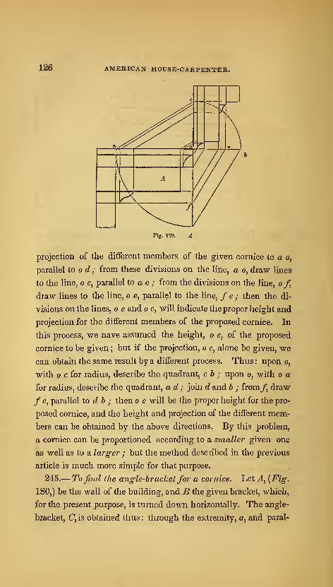
126 AMKRICAN HOUSE-CARPENTER.
c
z:^'
-^t\
^.^^^ ^-pe
1
1
////\r
KA
///A 1/ /
/
./
Tig. 179.
projection of the different members of the given cornice to a o,
parallel to o d ; from these divisions on the line, a o, draw lines
to the line, o c, parallel to a c ; from the divisions on the line, of,
draw lines to the line, o e, parallel to the line, f e ; then the di-
visions on the lines, o e and o c, will indicate the proper height and.
projection for the different members of the proposed cornice. In
this process, we nave assumed the height, o e, of the proposed
cornice to be given ; but if the projection, o c, alone be given, we
can obtain the same result by a different process. Thus : upon o,
with c for radius, describe the quadrant, c b ; upon o, with o a
for radius, describe the quadrant, ad ; join d and b ; from/, draw
/ e, parallel to db ; then o e will be the proper height for the pro-
posed cornice, and the height and projection of the different mem-
bers can be obtained by the above directions. By this problem,
a cornice can be proportioned according to a s'rnaller given one
as well as to a larger ; but the method described in the previous
article is much more simple for that purpose.
245.— To find the angle-bracketfor a cornice. Let A, {Fig.
180,) be the wall of the building, and B the given bracket, which,
for the present purpose, is turned down horizontally. The angle-
bracket, C, is obtained thus : through the extremity, a, and paral-
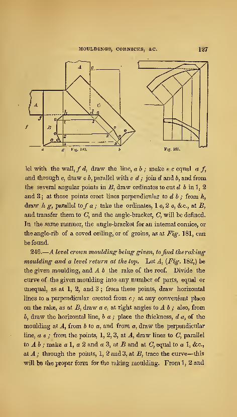
MOULDINGS, CORNICES, &C. 127
g Fig. 180. Fig. 181.
lei with the wall,/c?, draw the Ime, ah ; make e c equal a /,
and through c, draw c 6, parallel with e d ; join rf and 6, and from
the several angular points in B^ draw ordinates to cut c? 6 in 1, 2
and 3 ; at those points erect lines perpendicular to d b ; from h,
draw h g, parallel to/ a ; take the ordinates, 1 o, 2 o, <fcc., at 5,
and transfer them to C, and the angle-bracket, C, will be defined.
In the same manner; the angle-bracket for an internal cornice, or
the angle-rib of a coved ceiling, or of groins, as at Fig. 181, can
be found,
246.
—
A level crown moulding being given, tofind the raking
moulding and a level return at the top. Let A, [Fig. 182,) be
the given moulding, and A b the rake of the roof. Divide the
curve of the given moulding into any number of parts, equal or
unequal, as at 1, 2, and 3 ; from these points, draw horizontal
lines to a perpendicular erected from c; at any convenient place
on the rake, as at B, draw a c, at right angles to ^ 6 ; also, from
5, draw the horizontal line, ha; place the thickness, d «, of the
moulding at J., from b to a, and from a, draw the perpendicular
line, a e ; from the points, 1, 2, 3, at A, draw lines to C, parallel
io Ah ; make al, a 2 and a3, ai B and at C, equal to a 1, &c.,
at A ; through the points, 1, 2 and 3, at B, trace the curve—this
will be the proper fonu for the raking moulding. From 1, 2 and
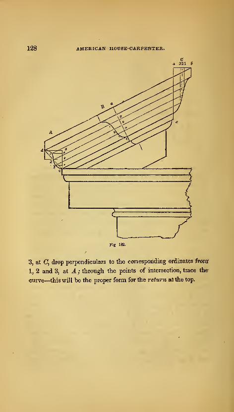
128 AMERICAN HOUSE-CARP£]^T£R.
Fig 182.
3, at C, drop perpendiculars to the corresponding ordinates from?
1, 2 and 3, at A ; through the points of intersection, trace the
curve—this will be the proper form for the return at the top.
SECTION IV.—FRAMING.
247.—This subject is, to the carpenter, of the highest impor-
tance ; and deserves more attention and a larger place in a volume
of this kind, than is generally allotted to it. Something, indeed,
has been said upon the geometrical principles, by which the seve-
ral lines for the joints and the lengths of timber, may be ascer-
tained;yet, besides this, there is much to be learned. For how-
ever precise or workmanlike the joints may be made, what will
it avail, should the system of framing, from an erroneous position
of its timbers, &c., change its form, or become incapable of sus-
taining even its own weight ? Hence the necessity for a know-
ledge of the laws of pressure and the strength of timber. These
being once understood, we canwith confidence determine the best
position and dimensions for the several timbers which compose a
floor or a roof, a partition or a bridge. As systems of framing
are more or less exposed to heavy weights and strains, and, in
case of failure, cause not only a loss of labour and material, but
frequently that of life itself, it is very important that the materials
employed be of the proper quantity and quality to serve their des-
tination. And, on the other hand, any superfluous material is not
only useless, but a positive injury, it being an unnecessary load
upon the points of support. It is necessary, therefore, to know
IT
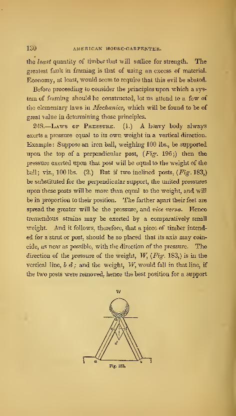
130 AMERICAN HOUSE-CARPENTER.
the least quantity of timber that will suffice for strength. The
greatest fault in framing is that of using an excess of material.
Economy, at least, would seem to require that this evil be abated.
Before proceeding to consider the principles upon which a sys-
tem of framing should be constructed, let us attend to a few of
the elementary laws in Mechanics, which will be found to be of
great value in determining those principles.
248.
—
Laws of Pressure. (1.) A heavy body always
exerts a pressure equal to its own weight in a vertical direction.
Example: Suppose an iron ball, weighing 100 lbs., be supported
upon the top of a perpendicular post, {Fig. 196;) then the
pressure exerted upon that post will be equal to the weight of the
ball; viz., 100 lbs. (2.) But if two inclined posts, {Fig. 183,)
be substituted for the perpendicular support, the united pressures
upon these posts will be more than equal to the weight, and will
be in proportion to their position. The farther apart their feet are
spread the greater will be the pressure, and vice versa. Hence
tremendous strains may be exerted by a comparatively small
v.^eight. And it follows, therefore, that a piece of timber intend-
ed for a strut or post, should be so placed that its axis may coin-
cide, as near as possible, with the direction of the pressure. The
direction of the pressure of the weight, TF, {Fig. 183,) is in the
vertical line, h d ; and the weight, W, would fall in that line, if
the two posts were removed, hence the best position for a support
w
Fig. 183.

FRAMING. 131
for the weight would be in that line. But, as it rarely occurs in
systems of framing that weights can be supported by any single
resistance, they requiring generally two or more supports, (as in
the case of a roof supported by its rafters,) it becomes important,
therefore, to know the exact amount of pressure any certain
weight is capable of exerting upon oblique supports. This can
be ascertained by the following process.
Let a h and h c, {Fig.. 183,) represent the axes of two sticks of
timber supporting the weight, TF; and let the weight, W^ be
equal to 6 tons. Make the vertical line, h t/, equal to 6 inches;
from c?, draw df^ parallel to a 6, and d e., parallel to c 6 ; then
the line, h e, will be found to be 31 inches long, which is equal to
the number of tons that the weight, Vi^ exerts upon the post, a h.
The pressure upon the other post is represented by 6/, which in
this case is of the same length as h e. The posts being inclined
at equal angles to the vertical line, h c?, the pressure upon them is
equal. Thus it will be found that the weight, which weighs
only 6 tons, exerts a pressure of 7 tons ; the amount being in-
creased because of the oblique position of the supports. Thelines, e h, h f,f d and d e, compose what is called the parallelo-
gram of forces. The oblique strains exerted by any one force,
therefore, may always be ascertained, by making h d equal, (upon
any scale of equal parts,) to the number of lbs., cwts., or tons
contained in the weight, TF, and b e will then represent the num-
ber of lbs., cwts., or tons with which the timber, a 6, is pressed,
and hf that exerted upon h c.
Fig. 184
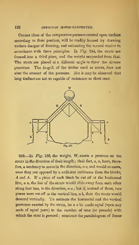
132 AMERICAN HOUSE-CARPENTER.
Correct ideas of the comparative pressure exerted upon timbers
according to their position, will be readily formed by drawing
various designs of framing, and estimating the several strains in
accordance with these principles. In Fig. 184, the struts are
framed into a third piece, and the weight suspended from that.
The struts are placed at a different angle to show the diverse
pressures. The length of the timber used as struts, does not
alter the amount of the pressure. But it may be observed that
long timbers are not so capable of resistance as short ones.
Fig. 185.
249.—In Fig. 185, the weight, TF, exerts a pressure on the
struts in the direction of their length ; their feet, n, n, have, there-
fore, a tendency to move in the direction, n o, and would so move,
were they not opposed by a suifficient resistance from the blocks,
A and A. If a piece of each block be cut off at the horizontal
line, a n, the feet of the struts would slide away from each other
along that line, in the direction, n a ; but if, instead of these, two
pieces were cut off at the vertical line, n &, then the struts would
descend vertically. To estimate the horizontal and the vertical
pressures exerted by the struts, let w o be made equal (upon any
scale of equal parts) to the number of tons (or pounds) with
which the strut is pressed; construct the parallelogram of forces
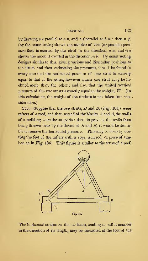
FRAMING. 133
by drawing o e parallel to a n, and 0/ parallel to 5 ?*; then n f,
(by the same scale,) shows the number of tons (or pounds) pres-
sure that is exerted by the strut in the direction, 71 a, and tz e
shows the amount exerted in the direction, n b. By constructing
designs similar to this, giving various and dissimilar positions to
the struts, and then estimating the pressures, it will be found in
every case that the horizontal pressure of one strut is exactly
equal to that of the other, however much one strut may be in-
clined more than the other ; and also, that the united vertical
pressure of the two struts is exactly equal to the weight, W. (In
this calculation, the weight of the timbers is not taken into con-
sideration.)
250.—Suppose that the two struts, B and B, {Fig. 185,) were
rafters of a roof, and that instead of the blocks, A and A, the walls
of a building were the supports : then, to prevent the walls from
being thrown over by the thrust of B and B, it would be desira-
ble to remove the horizontal pressure. This may be done by uni-
ting the feet of the rafters with a rope, iron rod, or piece of tim-
ber, as in Fig. 186. This figure is similar to the truss of a roof.
Fi^. 186.
The horizontal strains on the tie-beam, tending to pull it asunder
in the direction of its length, may be measured at the foot of the
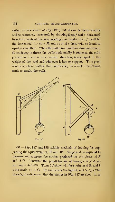
134 AMERICAN HOUSE-CARPENTER.
rafter, as was shown at Fig. 185 ; but it can be more readily
and as accurately measured, by drawing from/and e horizontal
lines to the vertical line, b d, meeting it in o and o; then/ o will be
the horizontal thrust at B, and e oat A ; these will be found to
equal one another. When the rafters of a roof are thus connected,
all tendency to thrust the walls horizontally is removed, the only
pressure on them is in a vertical direction, being equal to the
weight of the roof and whatever it has to support. This pres-
snare is beneficial rather than otherwise, as a roof thus formed
tends to steady the walls.
Fig. 188.
251..
—
Fig. 187 and 188 exhibit methods of framing for sup-
porting the equal weights, W and W. Suppose it be required to
measure and compare the strains produced on the pieces, A Band .4 C. Construct the parallelogram of forces, e h f d, ac-
cording to A rt. 248. Then h/ show will the strain on A B, and b
e the strain on A C. By comparing the figures, b d being equal
in each, it will be seen that the strains in Fig. 187 are about three

FRAMING. 135
times as great as those in Fig. 188 : the position of the pieces,
A B and A C, in Fig. 188, is therefore far preferable.
This and the preceding examples exempHfy, in a measure, the
resolution offorces ; viz., the finding of two or more forces, which,
acting in different directions, shall exactly balance the pressure
of any given single force. Thus, in Fig. 185, supposing the
weight, TF, to be the greatest force that the two timbers, in their
present position, are capable of sustaining, then the Aveight, W,
is the given force, and the timbers are the two forces just equal to
the given force.
C Fig. 189.
252.—The composition of forces consists in ascertaining the
direction and amount of one force, which shall be just capable of
balancing two or m,ore given forces, acting in different directions.
This is only the reverse of the resolution of forces, and the two
are founded on one and the same principle, and may be solved in
the same manner. For example ; let A and B^ {Fig- 189,) be
two pieces of timber, pressed in the direction of their length to-
wards h—A by a force equal to 6 tons weight, and B equal to 9.
To find the directioji and amount of pressure they would unitedly
exert, draw the lines, b e and h f in a line with the axes of the
timbers, and make b e equal to the pressure exerted by B, viz., 9;
also make b f equal to the pressure on A, viz., 6, and complete
the parallelogram of forces, ebfd; then b d, the diagonal of the
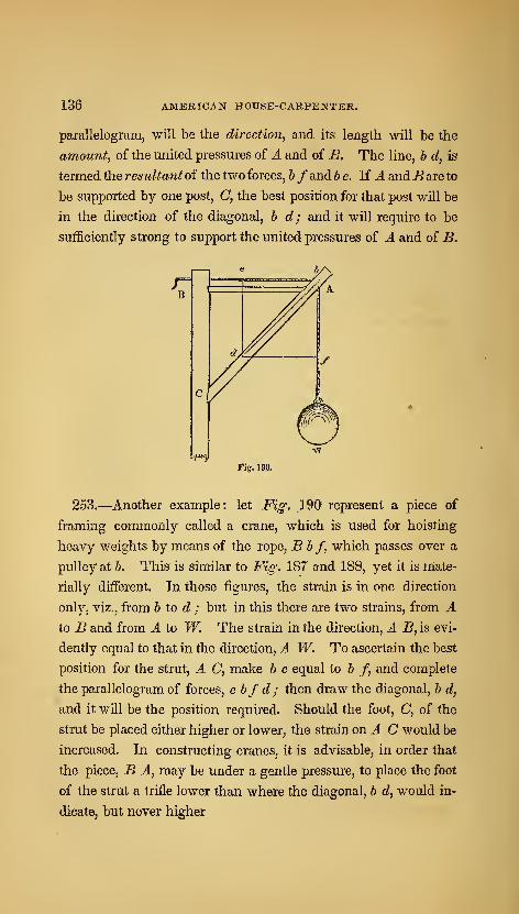
136 AMERICAN HOUSE-CARPENTER.
parallelogram, will be the direction, and its length will be the
amount, of the united pressures of A and of B. The line, b d, is
termed the resultant of the two forces, hfand he. If J. andB are to
be supported by one post, C, the best position for that post will be
in the direction of the diagonal, h d; and it will require to be
sufficiently strong to support the united pressures of A and of B.
Fig. ISO,
253.—Another example: let Fig. 190 represent a piece of
framing commonly called a crane, which is used for hoisting
heavy weights by means of the rope, Bhf, which passes over a
pulley at h. This is similar to Fig. 187 and 188, yet it is mate-
rially different. In those figures, the strain is in one direction
only, viz., from b to d ; but in this there are two strains, from Ato B and from A to W. The strain in the direction, A B,is evi-
dently equal to that in the direction, A W. To ascertain the best
position for the strut, A C, make b e equal to b /, and complete
the parallelogram of forces, e bfd; then draw the diagonal, b d,
and it v/ill be the position required. Should the foot, C, of the
strut be placed either higher or lower, the strain (m.AC would be
increased. In constructing cranes, it is advisable, in order that
the piece, B A, may be under a gentle pressure, to place the foot
of the strut a trifle lower than where the diagonal, b d, would in-
dicate, but never higher
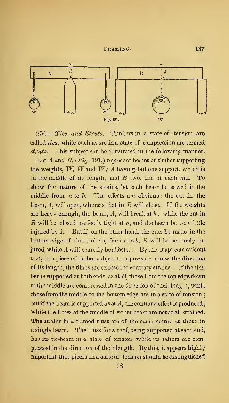
pRAMiNG. w
G7T
vi/lVv^,
Fig. 191.
Wy/V
254.— Ties and Struts. Timbers in a state of tension are
called ties, while such as are in a state of compression are termed
struts. This subject can be illustrated in the following manner.
Let A and B, {Fig. 191,) represent beams of timber supporting
the weights, W, W and W; A having but one support, which is
in the middle of its length, and B two, one at each end. To
show the nature of the strains, let each beam be sawed in the
middle from a to h. The eifects are obvious : the cut in the
beam. A, will open, whereas that in B will close. If the weights
are heavy enough, the beam, A, will break at h ; while the cut in
B will be closed perfectly tight at a, and the beam be very little
injured by it. But if, on the other hand, the cuts be made in the
bottom edge of the timbers, from c loh, B will be seriously in-
jured, while A will scarcely be affected. By this it appears evident
that, in a piece of timber subject to a pressure across the direction
of its length, the fibres are exposed to contrary strains. If the tim-
ber is supported at both ends, as at B, those from the top edge down
to the middle are compressed in the direction of their length, while
those from the middle to the bottom edge are in a state of tension;
but if the beam is supported as at J., the contrary effect is produced
;
while the fibres at the middle of either beam are not at all strained.
The strains in a framed truss are of the same nature as those in
a single beam. The truss for a roof, being supported at each end,
has its tie-beam in a state of tension, while its rafters are com-
pressed in the direction of their length. By this, it appears highly
important that pieces in a state of tension should be distinguished
18
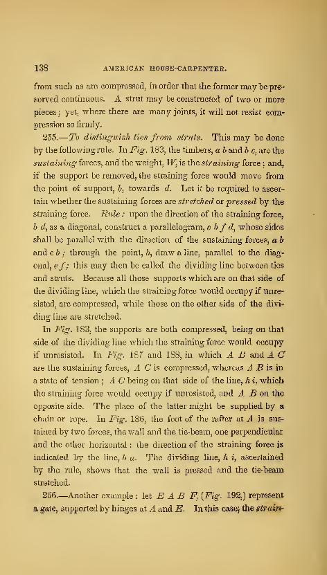
138 AMERICAN HOUSE-CARPENTER.
from such as are compressed, in order that the former may be pref"
served continuous. A strut may be constructed of two or more
pieces;
yet, where there are many joints, it will not resist com-
pression so firmly.
255.— To distinguish ties from struts. This may be done
by the following rule. In Fig. 183, the timbers, a b and b c, are the
sustaining forces, and the weight, W, is the straining force ; and^
if the support be removed, the straining force would move from
the point of support, &, towards d. Let it be required to ascer-
tain whether the sustaining forces are stretched or pressed by the
straining force. Rule : upon the direction of the straining force,
6 c?, as a diagonal, construct a parallelogram, e bfd, whose sides
shall be parallel with the direction of the sustaining forces, a b
and ch ; through the point, Z>, draw a line, parallel to the diag-
onal, ef; this may then be called the dividing line between ties
and struts. Because all those supports which are on that side of
the dividing line, which the straining force would occupy if unre-
sisted, are compressed, while those on the other side of the divi-
ding line are stretched.
In Fig. 183, the supports are both compressed, being on that
side of the dividing line which the straining force would occupy
if unresisted. In Fig. 187 and 188, in which A B and A Care the sustaining forces, A Cis compressed, whereas J. ^ is in
a state of tension ; A C being on that side of the line, h i, which
the straining force would occupy if unresisted, and J. ^ on the
opposite side. The place of the latter might be supplied by a
chain or rope. In Fig. 186, the foot of the rafter at A is sus-
tained by two forces, the wall and the tie-beam, one perpendicular
and the other horizontal : the direction of the straining force is
indicated by the line, b a. The dividing line, h i, ascertained
by the rule, shows that the wa,ll is pressed and the tie-beam
stretched.
256.—-Another example : let E A B F, [Fig. 192,) represent
a gate, supported by hinges at A and K. In this casej the strain^
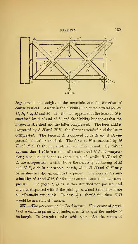
ing force is the weight of the materials, and the direction of
course vertical. Ascertain the dividing line at the several points,
G, B, I, J, H and F. It will then appear that the force at G is
sustained hj A G and G E^ and the dividing line shows that the
former is stretched and the latter compressed. The force atiJis
supported by A Ifand HE—the former stretched and the latter
compressed. The force at B is opposed hj H B and A B, one
pressed—the other stretched. The force at i^is sustained by Gi^and FEj G i^ being stretched and FE pressed. By this it
appears that A B is in a state of tension, and E F, of compres-
sion; also, that A Hand G F sue stretched, while B H and GE are compressed : which shows the necessity of having A Hand G jP, each in one whole length, while B i^and G E may
be, as they are shown, each in two pieces. The force at /is sus-
tained by G /and J H, the former stretched and the latter com-
pressed. The piece, C Z>, is neither stretched nor pressed, and
could be dispensed with if the joinings at /and 1 could be made
as effectually without it. In case A B should fail, then C Dwould be in a state of tension.
257.— The pressure of inclined beams. The centre of gravi-
ty of a uniform prism or cylinder, is in its axis, at the middle of
its length. In irregular bodies with plain sides, the centre of
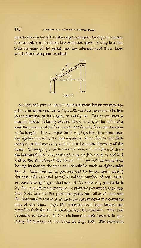
140 AMERICAN HOUSE-CARPENTER.
gravity may be found by balancing them upon the edge of a prism
in two positions, making a hne each time upon the body in a line
with the edge of the prism, and the intersection of those lines
•will indicate the point required.
Fiff. 193.
An inclined post or strut, supporting some heavy pressure ap-
plied at its upper end, as at Fig. 186, exerts a pressure at its foot
in the direction of its length, or nearly so. But when such a
beam is loaded uniformly over its whole length, as the rafter of a
roof, the pressure at its foot varies considerably from the direction
of its length. For example, let A B, {Fig. 193,) be a beam lean-
ing against the wall, B c, and supported at its foot by the abut-
ment, A, in the beam, A c, and let o be the centre of gravity of the
beam. Through o, draw the vertical line, b d, and from B, draw
the horizontal line, B b, cutting b d in b ; join b and A, and b Awill be the direction of the thrust. To prevent the beam from
loosing its footing, the joint at A should be made at right angles
to b A. The amount of pressure will be found thus : let b c?,
(by any scale of equal parts,) equal the number of tons, cwts.,
or pounds weight upon the beam, A B ; draw d e, parallel to Bb ; then b e, (by the same scale,) equals the pressure in the direc-
tion, b A ; and e d, the pressure against the wall at B—and also
the horizontal thrust at A, as these are always equal in a construc-
tion of this kind. Fig. 194 represents two equal beams, sup-
ported at their feet by the abutments in the tie-beam. This case
is similar to the last ; for it is obvious that each beam is in pre-
cisely the position of the beam in Fig. 193. The horizontal
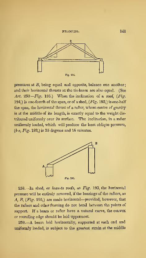
FRAMING. 141
Fig. 194.
pressures at B, being equal and opposite, balance one another
;
and their horizontal thrusts at the tie-beam are also equal. (See
Art. 250
—
Fig. 186.) When the inclination of a roof, {Fig.
194,) is one-fourth of the span, or of ashed, {Fig. 193,) is one-half
the span, the horizontal thrust of a rafter, whose centre of gravity
is at the middle of its length, is exactly equal to the weight dis-
tributed uniformly over its surface. The inclination, in a rafter
uniformly loaded, which will produce the least oblique pressure,
{b e, Fig. 193,) is 35 degrees and 16 minutes.
L-v^fig. 195.
258.—In shed, or lean-to roofs, as Fig. 193, the horizontal
pressure will be entirely removed, if the bearings of the rafters, as
A, B, {Fig. 195,) are made horizontal—provided, however, that
the rafters and other framing do not bend between the points of
support. If a beam or rafter have a natural curve, the convex
or rounding edge should be laid uppermost.
259.—A beam laid horizontally, supported at each end and
uniformly loaded, is subject to the greatest strain at the middle

142 AMERICAN HOUSE-CARPENTER.
of its length. The amount of pressure at that point is equal to
half of the whole load sustained. The greatest strain coming
upon the middle of such a beam, mortices, large knots and other
defects, should be kept as far as possible from that point ; and, in
resting a load upon a beam, as a partition upon a floor beam, the
weight should be so adjusted that it will bear at or near the ends.
(See Art. 282.)
260.—The resistance of timber. When the stress that a
given load exerts in any particular direction, has been ascertain-
ed, before the proper size of the timber can be determined for the
resistance of that pressure, the strength of the kind of timber to
be used must be known. The following rules for calculating the
resistance of timber, are based upon the supposition that the tim-
ber used be of what is called " merchantable" quality—that is,
strait-grained, seasoned, and free from large knots, splits, decay,
(&C.
Fig. 198.
The strength of a piece of timber, is to be considered in ac-
cordance with the direction in which the strain is applied upon

FRAMING. 143
It. When it is compressed in the direction of its length, as in
Fig. 196, its strength is termed the resistance to compression.
When the force tends to pull it asunder in the direction of its
length, {Aj Fig. 197,) it is termed the resistance to tension.
And when strained by a force tending to break it crosswise, as at
Fig. 198, its strength is called the resistance to cross strains.
261.
—
Resistance to compression. When the height of a
piece of timber exceeds about 10 times its diameter if round, or
10 times its thickness if rectangular, it will bend before crushing.
The first of the following cases, therefore, refers to such posts as
would be crushed if overloaded, and the other two to such as
would bend before crushing. In estimating the strength of tim-
ber for this kind of resistance, it is provided in the following
rules that the pressure be exactly in a line with the axis of the
post.
Case 1.—To find the area of a post that will safely bear a given
weight—when the height of the post is less than 10 times its least
thickness. Rule.—Divide the given weight in pounds by 1000
for pine and 1400 for oak, and the quotient will be the least area
of the post in inches. This rule requires that the area of the
abutting surface be equal to the result : should there be, there-
fore, a tenon on the end of the post, this quotient will be too small.
Example.—What should be the least area of a pine post that will
safely sustain 48,000 pounds ? 48,000, divided by 1000, gives
48—the required area in inches. Such a post may be 6x8
inches, and will bear to be of any length within 10 times 6 inches,
its least thickness.
Case 2.—To find the area of a rectangular post that will
safely bear a given weight—when its height is 10 times its least
thickness or more. Rule.—Multiply the given weight or pres-
sure in pounds by the square of the length in feet ; and multi-
ply this product by the decimal, "0015, for oak, -0021, for pitch
pine and '0016 for white pine; then divide this product by the
breadth in inches, and the cube-root of the quotient will be the
144 AMERICAN HOUSE-dARPENTEit.
thickness in inches. Example.—What should be the thickness
of a pine post, 8 feet high and 8 inches wide, in order to support
a weight of 12 tons, or 26,880 pounds ? The square of the length
is 64 feet; this, multiplied by the weight in pounds, gives
1,730,320; this product, multiplied by the decimal, -0016, gives
2768-512; and this again, divided by the breadth in inches, gives
346*064 ; by reference to the table of cube-roots in the appendix,
the cube-root of this number will be foufid to be 7 inches large—
•
which is the thickness required. The stiffest rectangular post is
that in which the sides are as 10 to 6.
Case 3.—To find the area of a round, or cylmdrical. post, that
will safely bear a given weight—when its height is 10 times its
least diameter or more. Rule.—Multiply the given weight or
pressure in pounds by 1*7, and the product by '0015 for oak, -0021
for pitch pine and '0016 for white pine ; then multiply the square^
root of this product by the height in feet, and the square-root of
the last product will be the diameter required, in inches. Exam^
j>Ze.—What should be the diameter of a cylindrical oak post, 8
feet high, in order to support a weight of 12 tons, or 26,880
pounds ? This weight in pounds, multiplied by 1*7, gives 45,696
;
and this, by "0015, gives 68-544; the square-root of this product
is (by the table in the appendix) 8-28, nearly—which, multiplied
by 8, gives 66-24; the square-root of this number is 8-14, nearly
;
therefore, 8-14 inches is the diameter required.
Experiments hav^e shown that the pressure should neVerbe
more than 1000 pounds per square inch on a joint in yellow pine
—when the end of the grain of one piece is pressed against the
side of the grain of the other.
262.
—
Resistance to tension. A bar of oak of an inch square^
pulled in the direction of its length, has been torn asunder by a
weight of - - . - 11,500 lbs.
Of white pine - - - 11,000
Of pitch pine - - - 10,000
FRAMING. 145
Therefore, "vvlien the strain is applied in a line with the axis of
the piece, the folloAving rule must be observed.
To find the area of a piece of timber to resist a given strain in
the direction of its length. Rule.—Divide the given weight to
be sustained, by the weight that will tear asunder a bar an inch
square of the same kind of wood, (as above.) and the product will
be the area in inches of a piece that will just sustain the given
weight ; but the area should be at least 4 times this, to safely
sustain a constant load of the given weight. Example.—What
should be the area of a stick of pitch pine timber, which is re-
quired to sustain safely a constant load of 60,000 pounds ? 60,000,
divided by 10,000, (as above,) gives 6, and this, multiplied by 4,
give 24 inches—the answer.
263.
—
Resistance to cross strains. To find the scantling of a
piece of timber to sustain a given weight, when such piece is
supported at the ends in a horizontal position.
Case 1.—When the breadth is given. Rule.—-Mitltiply the
square of the length in feet by the weight in pounds, and this
product by the decimal, "009, for oak, 'Oil for white pine and -016
for pitch pine ;divide the product by the breadth in inches, and
the cube-root of the quotient will be the depth required in inches.
Example.—What should be the depth of a beam of white pine,
having a bearing of 24 feet and a breadth of 6 inches, in order to
support 900 pounds ? The square of 24 is 576, and this, multiplied
by 900, gives 518-400; and this again, by -Oil, gives 5702-400;
this, divided by 6, gives 950'400; the cube-root of which is 9 '83
inches—the depth required.
Case 2.—When the depth is given. Rule.—Multiply the
square of the length in feet by the weight in pounds, and multi-
ply this product by the decimal, '009, for oak, 'Oil for white pine
and '016 for pitch pine ; divide the last product by the cube of
the depth in inches, and the quotient will be the breadth in inches
required. Example.—What should be the breadth of a beam of
oak, having a bearing of 1 6 feet and a depth of 12 inches^ mId
146 AMERICAN HOUSE-CARPENTER.
order to support a weight of 4000 pounds'? The square of 16 is
256, which, multiplied by 4000, gives 1,024,000 ; this, multiplied
by -009, gives 9216 ; and this again, divided by 1728, the cube of
12, gives 5} inches—^which is the breadth required.
Case 3.—When the breadth bears a certain proportion to the
depth. When neither the breadth nor depth is given, it will be
best to fix on some proportion which the breadth should have to
the depth ; for instance, suppose it be convenient to make the
breadth to the depth as 0*6 is to 1, then the rule would become as
follows : Rule.—Multiply the weight in pounds by the decimal,
•009, for oak, "Oil for white pine and "016 for pitch pine; divide
the product by 0-6, and extract the square-root ; multiply this root
by the length in feet, and extract the square-root a second time,
which will be the depth in inches required. The breadth is
equal to the depth multiplied by the decimal, 0-6. It is obvious
that any other proportion of the breadth and depth may be ob-
tained by merely changing the decimal, 0'6, in the rule. Exam-
ple.—What should be the depth and breadth of a beam of pitch
pine, having a proportion to one another as 6 to 1, and a bearing
of 22 feet, in order to sustain a ton weight, or 2240 pounds ?
This, multiplied by '016, gives 35"84, which, divided by 0'6,
gives 59-73 ; the square-root of this is T'T, which, multiplied by
22, the length, gives 169'4; the square-root of this is 13—which
is the depth required. Then 13, multiplied by 0*6, gives 7'8
inches—the required breadth.
Case 4.—When the beam is inclined, as A B, Fig: 193.
Rule.—Multiply together the weight in pounds, the length of the
beam in feet, the horizontal distance, A c, between the supports,
in feet, and the decimal, -009, for oak, "Oil for white pine, and
•016 for pitch pine; divide this product by 0*6, and the fourth
root of the quotient will give the depth in inches. The breadth
is equal to the depth multiplied by the decimal, 0'6. Example.—What should be the size of an oak beam, the sides to bear a pro-
portion to one another as 0-6 to 1, in order to support a ton weight,
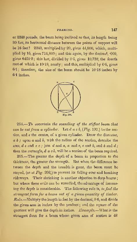
FRAMING. 147
or 2240 pounds, the beam being inclined so that, its length being
20 feet, its horizontal distance between the points of support will
be 16 feet? 2240, multiplied by 20, gives 44,800, which, multi-
plied by 16, gives 716,800 ; and this again, by the decimal, -009,
gives 6451-2 ; this last, divided by 0-6, gives 10,752, the fourth
root of which is 10-18, nearly ; and this, multiplied by 0-6, gives
6-1 ; therefore, the size of the beam should be 10*18 inches by
6-1 inches.
Fig. 199.
264.— To ascertain the scantling of the stiffest beam that
can he cut from a cylinder. Let d a c h, {Fig. 199,) be the sec-
tion, and e the centre, of a given cylinder. Draw the diameter,
ah ; upon a and 6, with the radius of the section, describe the
arcs, d e and e c ; join d and a, a and c, c and 6, and h and d ;
then the rectangle, d a ch^ will be a section of the beam required.
265.—The greater the depth of a beam in proportion to the
thickness, the greater the strength. But when the difference be-
tween the depth and the breadth is great, the beam must be
stayed, (as at Fig. 202,) to prevent its falling over and breaking
sideways. Their shrinking is another objection to deep beams
;
but where these evils can be remedied, the advantage of increas-
ing the depth is considerable. The following rule is, to find the
strongestform for aheam out of a given quantity of timher.
iSwZe.^Multiply the length in feet by the decimal, 0-6, and divide
the given area in inches by the product ; and the square of the
quotient will give the deptli in inches. Example.—"What is the
strongest form for a beam whose given area of section is 48

148 AMERICAN HOUSE-CARPENTER.
inches, and length of bearing 20 feet ? The length in feet, 20,
multiplied by the decimal, 0-6, gives 12; the given area in inches,
48, divided by 12, gives a quotient of 4, the square of v/hich is
16—this is the depth in inches ; and the breadth must be 3
inches. A beam 16 inches by 3 vi^ould bear twice as much as a
square beam of the same area of section; which shows how im-
portant it is to make beams deep and thin. In many old build-
ings, and even in new ones, in country places, the very reverse of
this has been practised ; the principal beams being oftener laid
on the broad side than on the narrower one.
266.
—
Systems of Framing. In the various parts of framing
known as floors, partitions, roofs, bridges, &c., each has a specific
object; and, in all designs for such constructions, this object
should be kept clearly in view ; the various' parts being so dis-
posed as to serve the design with the lerst quantity of material.
The simplest form is the best, not only because it is the most
economical, but for many other reasons. The great number of
joints, in a complex design, render the construction liable to de-
rangement by multiplied compressions, shrinkage, and, in conse-
quence, highly increased oblique strains; by which its stability
and durability are greatly lessened.
FLOORS,
267.—Floors have been constructed in various ways, and are
known as slngle-joisted, double, and framed. In a single-
joisted floor, the timbers, or floor-joists, are disposed as is shown in
Fig. 200. Where strength is the principal object, this manner
of disposing the floor-joists is far preferable ; as experiments have
proved that, with the same quantity of material, single-joisted
floors are much stronger than either double or framed floors.
To obtain the greatest strength, the joists should be thin and
deep.
268.— To find the depth of a joist, the length of hearing
and thickness being given, when the distancefrom ceritres is

FRAMING. 149
Fig. 200.
12 inches. jRz^ie.—Divide the square of the length in feet, by
the breadth in inches ; and the cube-root of the quotient, multi-
pUed by 2-2 for pine, or 2-3 for oak, will give the depth in inches.
Example.—What should be the depth of floor-joists, having a
bearing of 12 feet and a thickness of 3 inches, when said joists
are of pine and placed 12 inches from centres ? The square of
12 is 144, which, divided by 3, gives 48 ; the cube-root of this
number is 3-63, which, multiplied by 2*2, gives 7'988 inches,
the depth required ; or 8 inches will be found near enough for
practice.
269.—Where chimneys, flues, stairs, &c., occur to interrupt
the bearing, the joists are framed into a piece, (6, Fig. 201,)
called a trimmer. The beams, a, «, into which the trimmer is
framed, are called trimming-bemns, trimm,ing-joist.9, or car-
riage-beams. They need to be stronger than the commion joists,
in proportion to the number of beams, c, c, which they support.
The trimmers have to be made strong enough to support half the
weight which the joists, c, c, support, (the wall, or anotlier trim-
mer, at the other end supporting the other half,) and the carriage-

ISO AMERICAN HOUSE-CARPENTER.
beams must each be strong enough to support half the weight
which the trimmer supports. In calculating for the dimensions
of floor-timbers, regard must be had to the fact that the weight
which they generally support—such as persons of 150 pounds
moving over the floor—exerts a much greater influence than
equal weights at rest. When the trimmer, 6, is not more dis-
tant from the bearing, d, than is necessary for ordinary hearths,
&c., it will be sufficient to add \ of an inch to the thickness of
the carriage-beam for every joist, c, that is supported. Thus, if
the thickness of c is 3 inches, and the number of joists supported
be 6, add 6 eighths, or f of an inch, making the carriage-beams
3| inches thick. It is generally the practice in dwellings to make
the carriage-beam, in all situations, one inch thicker than the
common joists. But it is well to have a rule for determining the
size more accurately in extreme cases.
270.—When the bearing exceeds 8 feet, there should be struts,
as a and a, {Fig. 202,) well nailed between the joists. These
will prevent the turning or twisting of the floor-joists, and will
greatly stifien the floor. For, in the event of a heavy weight
resting upon one of the joists, these struts will prevent that joist
from settling below the others, to the injury of the plastering
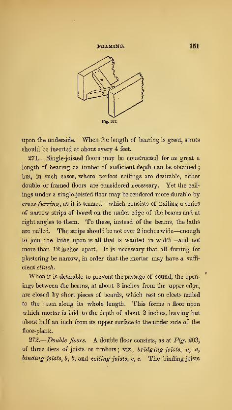
FRAMING. 161
Fig. 202.
upon the underside. When the length of bearing is great, struts
should be inserted at about every 4 feet.
271.—Single-joisted floors may be constructed for as great a
length of bearing as timber of sufficient depth can be obtained;
but, in such cases, where perfect ceilings are desirable, either
double or framed floors are considered necessary. Yet the ceil-
ings under a single-joisted floor may be rendered more durable by
cross-furring, as it is termed—which consists of nailing a series
of narrow strips of board on the under edge of the beams and at
right angles to them. To these, instead of the beams, the laths
are nailed. The strips should be not over 2 inches wide—enough
to join the laths upon is all that is wanted in width—and not
more than 12 inches apart. It is necessary that all furring for
plastering be narrow, in order that the mortar may have a suffi-
cient clinch.
When it is desirable to prevent the passage of sound, the open-
ings between the beams, at about 3 inches from the upper edge,
are closed by short pieces of boards, which rest on elects nailed
to the beam along its whole length. This forms a floor upon
which mortar is laid to the depth of about 2 inches, leaving but
about half an inch from its upper surface to the under side of the
floor-plank.
272.
—
Double floors. A double floor consists, as at Fig. 203,
of three tiers of joists or timbers ; viz., bridging-joists, a, a,
hiiiding-joists, b, b, and ceiling-joists, c, c. The binding-joists

152 AMERICAN HOUSE-CARPENTER.
Fig. 203.
are the principal support, and of course reach from wall to wall.
The bridging-joists, which support the floor-plank, are laid upon
the binding-joists, to which they are nailed ; sometimes they are
notched into the binding-joists, but they are sufficiently firm
when well nailed. The ceiling-joists are notched into the under
side of the binders, and nailed ; they are the support of the lath
and plastering.
273.—Binders are laid 6 feet apart. At this distance the fol-
lowing rules will give the scantling.
Case 1.—To find the depth of a binding-joist, the length and
breadth being given. Rule.—Divide the square of the length in
feet, by the breadth in inches ; and the cube-root of the quotient,
multiplied by 3-42 for pine, or by 3*53 for oak, will give the depth
in inches. Example.—What should be the depth of a binding-
joist, having a length of 12 feet and a breadth of 6 inches, when
the kind of timber is pine 1 The square of 12 is 144, which, di-
vided by 6, gives 24 ; the cube-root of this is 2-88, which, multi-
plied by 3'42, gives 9*85, the depth in inches.
Case 2.—To find the breadth, when the depth and length are
given. Rule.—Divide the square of the length in feet, by the

FRAMING. 153
cube of the depth in inches ; and multiply the quotient by 40 for
pine, or by 44 for oak, which will give the breadth in inches.
Example.—What should be the breadth of a binding-joist, hav-
ing a length of 12 feet and a depth of 10 inches, when the kind
of wood is pine ? The cube of 10 is 1000 ; the square of 12 is
144 ; this, divided by 1000, gives a quotient of -144 ; and this
quotient, multiplied by 40y gives 5-76, the breadth in inches.
274.—Bridging-joists are laid from 12 to 20 inches apart. The
scantling may be four.d by the rule at Art. 268-
275.—Ceihng-joists are generally placed 12 inches apart from
centres. They are arranged to suit the length of the lath;this
being, in most cases, 4 feet long. What is said at Art. 271, in
regard to the width of furring for plastering, will apply to the
thickness of ceiling-joists.
To find the depth of a ceiling-joist, when the length of bearing
and thickness are given. Rule.—Divide the length in feet by
the cube-root of the breadth in inches ; and multiply the quotient
by 0*64 for pine, or by 0*67 for oak, which will give the depth in
inches. Example.—What should be the depth of a ceiling-joist
of pine, when the length of bearing is 6 feet and the thickness 2
inches 1 The length in feet, 6, divided by the cube-root of the
breadth in inches, 1-26, gives a quotient of 4*76, which, being
multiplied by the decimal, 0'64, gives 3 inches, the depth re-
quired.
When the thickness of a ceiling-joist is 2 inches, the depth in
inches will be equal to half the length of bearing in feet. Thus,
if the bearing is 6 feet, the depth will be 3 inches ; bearing. 8
feet, depth 4 inches, &c.
276.
—
Fram,ed floors. When a good ceiling is required, and
the distance of bearing is great, the binding-joists, instead of
reaching from wall to wall, are framed into girders. These are
heavy timbers, as d, {Fig. 204,) which reach from wall to wall,
being the chief support of the floor. Such an arrangement is
termed a.framed floor. The binding, the bridging and the ceil-
20
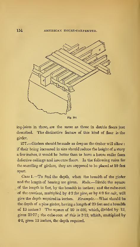
154 AMERICAN HOUSE-CARPENTKR.
Fig. 201.
ing-joists in these, are the same as those in double floors just
described. The distinctive feature of this kind of floor is the
girder.
277.—Girders should be made as deep as the timber will allow
:
if their being increased in size should reduce the height of a story
a few inches, it would be better than to have a house suffer from
defective ceilings and insecure floors. In the fallowing rules for
the scantling of girders, they are supposed to be placed at 10 feet
apart.
Case 1.—To find the depth, when the breadth of the girder
and the length of bearing are given. Rule.—Divide the square
of the length in feet, by the breadth in inches ; and the cube-root
of the quotient, multiplied by 4-2 for pine, or by 4-3 for oak, will
give the depth required in inches. Example.—What should be
the depth of a pine girder, having a length of 20 feet and a breadth
of 13 inches ? The square of 20 is 400, which, divided by 13,
gives 30-77 ; the cube-root of this is 3-12, which, multiplied by
4-2, gives 13 inches, the depth required.
FRAMING. 155
Case 2.—To find the breadth, when the length of bearing and
depth are given. Rule.—Divide the square of the length in feet,
by the cube of the depth in inches ; and the quotient, multiplied
by 74 for pine, or by 82 for oak, will give the breadth in inches.
Example.—What should be the breadth of a pine girder, having
a length of 18 feet and a depth of 14 inches ? The square of
the length in feet, 324, divided by the cube of the depth in
inches, 2744, gives -118; and this, multiplied by 74, gives 8-73
inches, the breadth required.
278.—When the breadth of a girder is more than about 12
inches, it is recommended to divide it by sawing from end to end,
vertically through the middle, and then to bolt it together with
the sawn sides outwards. This is not to strengthen the girder,
as some have supposed, but to reduce the size of the tiinber, in
order that it may dry sooner. The operation affords also an op-
portunity to examine the heart of the stick—a necessary precau-
tion;as large trees are frequently in a state of decay at the heart,
although outwardly they are seemingly sound. When the halves
are bolted together, thin slips of wood should be inserted between
them at the several points at which they are bolted, in order to
leave sufficient space for the air to circulate between. This
tends to prevent decay ; which will be found first at such parts
as are not exactly tight, nor yet far enough apart to permit the
escape of moisture.
279.—When girders are required for a long bearing, it is usual
to truss them; that is, to insert between the halves two pieces of
oak which are inclined towards each other, and which meet at
the centre of the length of the girder, like the rafters of a roof-
truss, though nearly if not quite concealed within the girder.
This, and many similar methods, though extensively practised,
are generally worse than useless ; since it has been ascertained
that, in nearly all such cases, the operation has positively weak-
ened the girder.
A girdermay be strengthened by mechanical contrivance, when
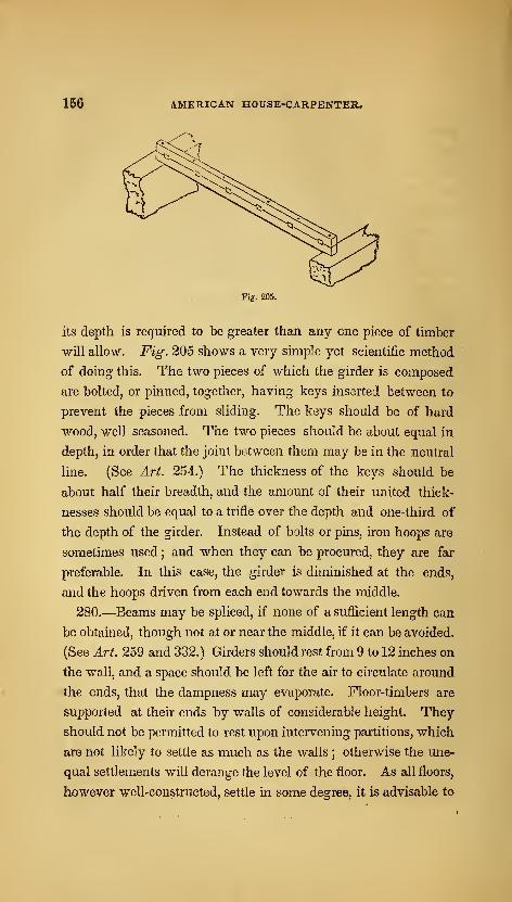
156 AMERICAN HOUSE-CARPENTER,
Fig. 205.
its depth is required to be greater than any one piece of timber
will allow. Fig. 205 shows a very simple yet scientific method
of doing this. The two pieces of which the girder is composed
are bolted, or pinned, together, having keys inserted between to
prevent the pieces from sliding. The keys should be of hard
wood, well seasoned. The two pieces should be about equal in
depth, in order that the joint between them may be in the neutral
line. (See Art. 254.) The thickness of the keys should be
about half their breadth, and the amount of their united thick-
nesses should be equal to a trifle over the depth and one-third of
the depth of the girder. Instead of bolts or pins, iron hoops are
sometimes used ; and when they can be procured, they are far
preferable. In this case, the girder is diminished at the ends,
and the hoops driven from each end towards the middle.
280.—Beams may be spliced, if none of a sufficient length can
be obtained, though not at or near the middle, if it can be avoided.
(See Art. 259 and 332.) Girders should rest from 9 to 12 inches on
the wall, and a space should be left for the air to circulate around
the ends, that the dampness may evaporate. Floor-timbers are
supported at their ends by walls of considerable height. They
should not be permitted to rest upon intervening partitions, which
are not likely to settle as much as the walls ; otherwise the une-
qual settlements will derange the level of the floor. As all floors,
however well-constructed, settle in some degree, it is advisable to
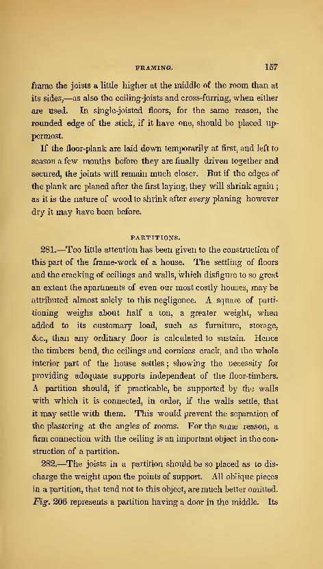
FRAMING. 157
frame the joists a little higher at the middle of the room than at
its sides,—as also the ceiling-joists and cross-furring, when either
are used. In single-joisted floors, for the same reason, the
rounded edge of the stick, if it have one, should be placed up-
permost.
If the floor-plank are laid down temporarily at first, and left to
season a few months before they are finally driven together and
secured, the joints will remain much closer. But if the edges of
the plank are planed after the first laying, they will shrink again;
as it is the nature of wood to shrink after every planing however
dry it may have been before.
PARTITIONS.
281.—Too little attention has been given to the construction of
this part of the frame-work of a house. The settling of floors
and the cracking of ceilings and walls, which disfigure to so great
an extent the apartments of even our most cosily houses, may be
attributed almost solely to this negligence. A square of parti-
tioning weighs about half a ton, a greater weight, when
added to its customary load, such as furniture, storage,
&c., than any ordinary floor is calculated to sustain. Hence
the timbers bend, the ceilings and cornices crack, and the whole
interior part of the house settles ; showing the necessity for
providing adequate supports independent of the floor-timbers.
A partition should, if practicable, be supported by the walls
with which it is connected, in order, if the walls settle, that
it may settle with them. This would prevent the separation of
the plastering at the angles of rooms. For the same reason, a
firm connection with the ceiling is an important object in the con-
struction of a partition.
282.—The joists in a partition should be so placed as to dis-
charge the weight upon the points of support. All oblique pieces
in a partition, that tend not to this object, are much better omitted.
Fig. 206 represents a partition having a door in the middle. Its
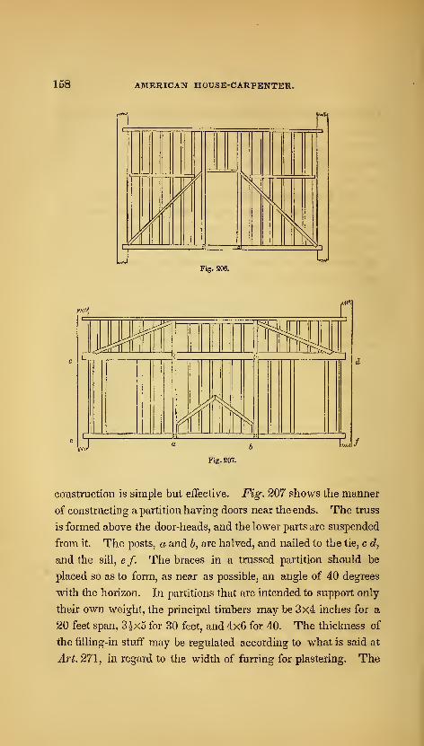
158 AMERICAN HOUSE-CARPENTER.
m
UFig. 206.
f)0
Fig. 207.
construction is simple but effective. Fig. 207 shows the manner
of constructing a partition having doors near the ends. The truss
is formed above the door-heads, and the lower parts are suspended
from it. The posts, a and 6, are halved, and nailed to the tie, c d,
and the sill, e /. The braces in a trussed partition should be
placed so as to form, as near as possible, an angle of 40 degrees
with the horizon. In partitions that are intended to support only
their own weight, the principal timbers may be 3x4 inches for a
20 feet span, 3|x5 for 30 feet, and 4x6 for 40. The thickness of
the filling-in stuff may be regulated according to what is said at
Art. 271, in regard to the width of furring for plastering. The

FRAMING. 159
fiUing-in pieces should be stiflened at about every three feet by-
short struts between.
All superfluous timber, besides being an unnecessary load upon
the points of support, tends to injure the stability of the plaster-
ing ; for, as the strength of the plastering depends, in a great mea-
sure, upon its clinch, formed by pressing the mortar through the
space between the laths, the narrower the surface, therefore, upon
which the laths are nailed, the less will be the quantity of plas-
tering unclinched, and hence its greater security from fractures.
For this reason, the principal timbers of the partition should have
their edges reduced, by chamfering ofl" the corners.
^.-
^ 3E
^
=|p=
^^
^-
Fiff.2U8.
283.—When the principal timbers of a partition require to be
large for the purpose of greater strength, it is a good plan to omit
the upright filling-in pieces, and in their stead, to place a few hori-
zontal pieces ; in order, upon these and the principal timbers, to
nail upright battens at the proper distances for lathing, as in Fig.
208. A partition thus constructed requires a little more space
than others ;but it has the advantage of insuring greater stability
to the plastering, and also of preventing to a good degree the con-
versation of one room from being heard in the other. When a
partition is required to support, in addition to its own weight, that
of a floor or some other burden resting upon it, the dimensions of

160 AMERICAN HOUSE-CARPENTER.
the timbers may be ascertained, by applying the principles which
regulate the laws of pressure and those of the resistance of tim-
ber, as explained at the first part of this section. The following
data, however, may assist in calculating the amount of pressure
upon partitions
:
284.—The weight of a square, (that is, a hundred square feet,)
of partitioning maybe estimated at from 1500 to 2000 lbs,; a
square of single-joisted flooring, at from 1200 to 2000 lbs. ; a
square of framed flooring, at from 2700 to 4500 lbs. ; and the
weight of a square of deafening^ (as described at the latter part
of Art. 271,) at about 1500 lbs.
When a floor is supported at two opposite extremities, and by a
partition introduced midway, one-half of the weight of the whole
floor will then be supported by the partition. As the settling of
partitions and floors, which is so disastrous to plastering, is fre-
quently owing to the shrinking of the timber and to ill-made
joints, it is very important that the timber be seasoned and the
work well executed.
ROOFS.*
285.—In ancient buildings, the Norman and the Gothic, the
walls and buttresses were erected so massive and firm, that it was
customary to construct their roofs without a tie-beam ; the walls
being abundantly capable of resisting the lateral pressure e:jierted
by the rafters. But in modern buildings, the walls are so slightly
built as to be incapable of resisting scarcely any oblique pressure
;
and hence the necessity of constructing the roof so that all
oblique and lateral strains may be removed; as, also, that instead
of having a tendency to separate the walls, the roof may contri-
bute to bind and steady them.
286.—In estimating the pressures upon any certain roof, for the
purpose of ascertaining the proper sizes for the timbers, calcula-
tion must be made for the pressure exerted by the wind, and, if
• See also Art. 228.
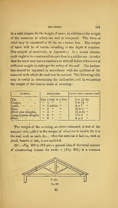
S'RAMIJfG; lei
in a cold climate, for the weight of snow, in addition to the weight
of the materials of which the roof is composed. The force of
wind may be calculated at 40 lbs. on a square foot. The weight
of snow will be of course according to the depth it acquires.
{See weight of materials, in Appendix.) In a severe climate,
roofs ought to be constructed steeper than in a milder one ; in order
that the snow may have a tendency to slide off before it becomes of
sufficient weight to endanger the safety of the roof The inclina-
tion should be regulated in accordance with the qualities of the
material with which the roof is to be covered. The following table
may be useful in determining the inclination^ and in estimating
the weight of the various kinds of covering •
MATERIAL. INCLINATION. WEIGHT UPON A SaUARE FOOT.
Tin, Rise 1 inch to a foot. 1 to \i lbs.
Copper,
Lead,
" 1 "
" 2 inches "1 to li "
4 to 7 "
Zinc, " 3 " " li to 2 "
Short pine shingles,
Long cypress shingles,
Slate,
u 5 a u
u 6 " "
u Q u u
lito2i ''
4 to 5 "
5 to 9 "
The weight of the covering, as above estimatedj is that of the
material only, added to the weight of whatever is used to fix it to
the roof, such as nails, &c. ; what the material is laid on, such as
plank, boards or lath, is not included.
287.
—
Fig. 209 to 212 give a general idea of the usual manner
of constructing trusses for roofs: c, {Fig. 209,) is a common
21
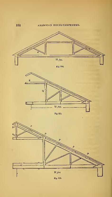
162 AMERICAN HOUSE-CARPENTER.
FRAMING. 163
rafter ; i2 is a principal rafter ; ^ is a king-post ; s is a strut ; S,
{Fig. 211,) is a straining-beam;Q is a queen-post
] T is a, tie-
beam ; and P, P, (Fig. 212,) are purlins. In constructing a roof
of importance, the trusses should be placed not over 10 feet apart,
the principal rafter supported by a strut at every purlin, the purlin
notched on instead of being framed into the principal rafters, and
the tie-beam supported at proper distances, according to the weight
of the ceiling or whatever else it is required to support.
288.—The dimensions of the timbers may be found in accord-
ance with the principles explained at the first part of this section;
but for general purposes, the following rules, deduced from the
experience of practical builders and from scientific principles,
may be found useful : these rules give the dimensions of the piece
at its smallest part.
289.— To Jind the dimensions of a king-post. Rule.—Mul-
tiply the length of the post in feet by the span in feet. Then
multiply this product by the decimal, 012, for pine, or by 0*13
for oak, which will give the area of the king-post in inches; and
divide this area by the breadth, and it will give the thickness; or
by the thickness for the breadth. Example.—What should be
the dimensions of a pine king-post, 8 feet long, for a roof having
a span of 25 feet 1 8 times 25 is 200 ; this, multiplied by the
decimal, 0-12, gives 24 inches for the area ; 4x6, therefore, would
be a good size at the smallest part.
290.— Tojiiid the dim,ensions of a queen-post. Rule.—Mul-
tiply the length in feet, of the queen-post or suspending-piece, by
that part of the length of the tie-beam it supports, also in feet.
This product, multiplied by the decimal, 0*27, for pine, or by 0-32
for oak, will give the area of the post in inches ; and dividing
this area by the thickness will give the breadth. Example.—The queen-posts in Fig. 210 support each ^ of the tie-beam,
which is 12f feet. To make them of pine, 6 feet long, what
should be their dimensions 7 12|j multiplied by 6, gives 76,

J.64 AMERICAN HOUSE-CARPENTER.
which, multiplied by 0:27, gives 20-52 ; which indicates a size of
about 4x5?.
291.— Tojind the dimensiojis of a tie-heam, that is required
to support a ceiling only. Rule.—Divide the length of the
longest unsupported part by the cube-root of the breadth ; and the
quotient, multiplied by 1-47 for pine, or by 1-52 for oak, will give
the depth in inches. Example.—The length of the longest un^
supported part of the tie-beam in Fig. 210 is 12f feet. What
should be the depth of the tie-beam, the breadth being 6 inches,
and the kind of wood, pine? The cube-root of 6 is 1-82, and 12f,
divided by 1*82, gives a quotient of 6'956; this, multiplied by
1'47, gives 10-225. The size of the tie-beam, therefore, maybe
6x10^. When there are rooms in the roof, the dimensions for
the tie-beam can be found by the rule for girders, {^Art. 277.)
292.— To find the dimensions of a principal rafter when
there is a king-post in the tniddle. Mule.—Multiply the square
of the length of the rafter in feet, by the span in feet ; and divide
the product by the cube of the thickness in inches. For pine,
multiply the quotient by '096, which will give the depth in
inches. Example.—^What should be the depth of a rafter of
pine, 22'36 feet long, and 6 inches thick, the roof having a span
of 40 feet ? The square of 22-36 is 500 nearly, this, multiplied by
40, gives 20000 ; and this, divided by 216, the cube of the thick-
ness, gives 92-59; which, multiplied by -096, equals 8-888. The
size of the rafter should, therefore, be 6x8|.
293.— To find the dimensions of a principal rafter when two
queen-posts are used instead of a king-p)ost. Rule.—The
same as the last, except that the decimal, 0-155, must be used
instead of 0-96. Exatnple.—What should be the dimensions of
a principal rafter, having a length of 14 feet, (as in Fig. 210,) and
a thickness of 6 inches, when the span of the roof is 38 feet
and the wood is pine? The square of 14 is 196, which, multi-
plied by 38, gives 7448 ; this, divided by 216, the cube of 6, gives
FRAMING, 165
34-48, which, multiplied by 0-155, gives 5-34. The size of the
rafter should, therefore, be 6x5|.
294.— To find the diniensions of a straining-heam. In or-
der that this beam may be the strongest possible, its depth should
be to its thickness as 10 is to 7. Rule.—Multiply the square-root
of the span in feet, by the length of the straining-beam in feet,
and extract the square-root of the product. Multiply this root by
0*9 for pine, which will give the depth in inches To find the
thickness, multiply the depth by the decimal, 0"7. Example.—
•
What should be the dimensions of a pine straining-beam, 12 feet
long, for a span of 38 feet ? The square-root of the span is 6*164,
which, multiplied by 12, gives 73-968; the square-root of this is
nearly 8-60, which, multiplied by 0-9, gives 7-74—the depth.
This, multiplied by 0*7, gives 5-418—the thickness. Therefore,
the beam should be 5fx7|, or 5|x8.
295.— To find the dimensions of struts and braces. Rule.—Multiply the square-root of the length supported in feet, by the
length of the brace or strut in feet ; and the square-root of the
product, multiplied by 0-8 for pine, will give the depth in inches;
and the depth, multiplied by the decimal, 0*6, will give the thick-
ness in inches. Example.—In Fig. 210, the part supported by
the brace or strut, o, is equal to half the length of the principal
rafter, or 7 feet ; and the length of the brace is 6 feet : what
should be the size of a pine brace 1 The square-root of 7 is 2-65,
which, multiplied by 6, gives 15-9; the square-root of this is 3-99,
which, multiplied by 0-8, gives 3-192—the depth. This, multi-
plied by 0-6, gives 1-9152, the thickness. Therefore, the brace
should be 2x3 inches.
It is customary to make the principal rafters, tie-beam, posts
and braces, all of the same thickness, that the whole truss may
be of the same thickness throughout.
296.— To find the dim,ensio?is of purlins. Rule.—Multiply
the cube of the length of the purlin in feet, by the distance the
purlins are apart in feet ; and the fourth root of the product for
pine will give the depth in inches ; or multiply by 1-04 to obtain
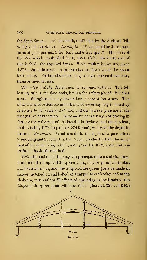
166 AMERICAN HOUSE-CARPENTER.
the depth for oak ; and the depth, multiplied by the decimal, 0'6,
will give the thickness. Example.—yfhoX should be the dimen-
sions of pine purlins, 9 feet long and 6 feet apart ? The cube of
9 is 729, which, multiplied by (>, gives 4374; the fourth root of
this is 8*13—the required depth. This, multiplied by 0*6, gives-
4'878—the thickness. A proper size for them would be about
5x8 inches. Purlins should be long enough to extend over two,
three or more trusses.
297.— To find the dimensions of coinmoji rafters. The fol-
lowing rule is for slate roofs, having the rafters placed 12 inches
apart. Shingle roofs may have rafters placed 2 feet apart. The
dimensions of rafters for other kinds of covering may be found by-
reference to the table at Art. 286, and the laws of pressure at the-
first part of this section. Rule.—Divide the length of bearing in
feet, by the cube-root of the breadth in inches ; and the quotient^
multiplied by 0*72 for pine, or 0-74 for oak, will give the depth in
inches. Example.—What should be the depth of a pine rafter,.
7 feet long and 2 inches thick ? 7 feet, divided by 1*26, the cube-
root of 2, gives 5-55, which, multiplied by 0.72, gives nearly 4
inches—the depth required.
298.—If, instead of framing the principal rafters and straining-
beam into the king and the queen posts, they be permitted to abut
against each other, and the king and the queen posts be made in
halves, notched on and bolted, or strapped to each other and to the
tie-beam, much of the ill effects of shrinking in the heads of the
king and the queen posts will be avoided. (See Art. 339 and 340.)
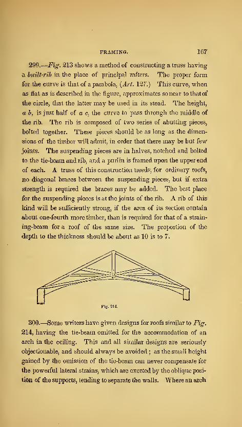
FRAMING. 167
290.
—
Fig, 213 shows a method of constructing a trass having
^ built-rib in the place of principal rafters. The proper form
for the curve is that of a parabola, {Art. 127.) This curve, when
as flat as is described in the figure, approximates so near to that of
the circle, that the latter may be used in its stead. The height,
u b, is just half of a c, the curve to pass through the middle of
the rib. The rib is composed of two series of abutting pieces,
bolted together. These pieces should be as long as the dimen-
sions of the timber will admit, in order that there may be but few
joints. The suspending pieces are in halves, notched and bolted
to the tie-beam and rib, and a purlin is framed upon the upper end
of each, A truss of this construction needs, for ordinary roofs,
no diagonal braces between the suspending pieces, but if extra
strength is required the braces may be added. The best place
for the suspending pieces is at the joints of the rib. A rib of this
kind will be sufiiciently strong, if the area of its section contain
about one-fourth more timber, than is required for that of a strain-
ing-beam for a roof of the same size. The proportion of the
depth to the thickness should be about as 10 is to 7.
Fig. 214.
300.—Some writers have given designs for roofs similar to Fig.
214, having the tie-beam omitted for the accommodation of an
arch in the ceiling. This and all similar designs are seriously
objectionable, and should always be avoided ; as the small height
gained by the omission of the tie-beam can never compensate for
the powerful lateral strains, which are exerted by the oblique posi-
tion of the supports, tending to separate the walls. Where an arch
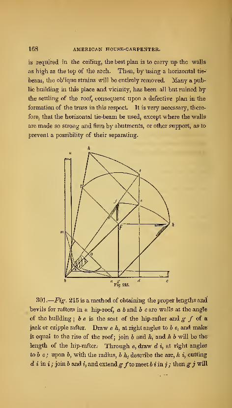
168 AMERICAN HOUSE-CARPENTER.
is required in the ceiling, the best plan is to carry up the walls
as high as the top of the arch. Then, by using a horizontal tie-
beam, the oblique strains will be entirely removed. Many a pub-
lic building in this place and vicinity, has been all but ruined by
the settling of the roof, consequent upon a defective plan in the
formation of the truss in this respect. It is very necessary, there-
fore, that the horizontal tie-beam be used, except where the walls
are made so strong and firm by abutments, or other support, as to
prevent a possibility of their separating.
a
}
\^t
^^
f
/t / 1
Fig, 215.
301.
—
Figi 215 is a method of obtaining the proper lengths and
bevils for rafters in a hip-roof, a h and h c are walls at the angle
of the building; 6 e is the seat of the hip-rafter and g f of sL
jack or cripple rafter. Draw e h, at right angles to b e, and make
it equal to the rise of the roof; join b and h, and h b will be the
length of the hip-rafter.- Through e^ draw d i, at right angles
to 6 c; upon 6, with the radius, b h^ describe the arc, h i, cutting
diini; join b and tj and extendgfto meet biinj ; then gj will
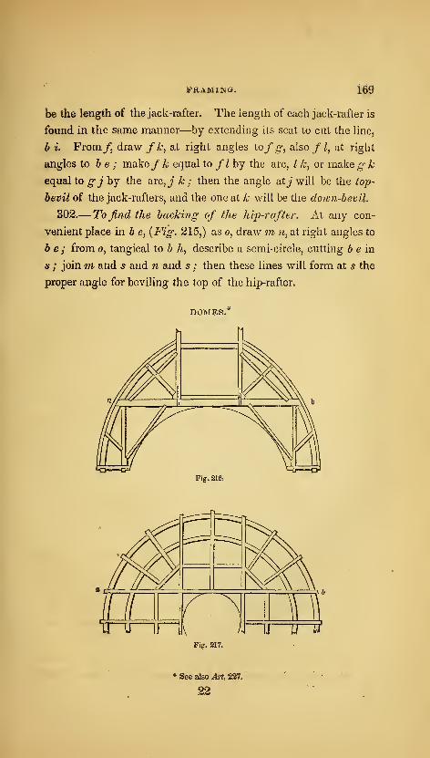
pkAmiijg. 160
be the length of the jack-rafter. The length of each jack-rafter is
found in the same manner—by extending its seat to cut the line,
b i. From/j draw f k, at right angles iofg, also f I, at right
angles to be; makefk equal to /^ by the arc, I k, or make g k
equal to g j by the arc, j k ; then the angle atJ will be the top-
bevil of the jack-rafters, and the one at k will be the down-bevil.
302.— To find the backing of the hip-rafter. At any con-
venient place in b e, {Fig. 215,) as o, draw m w, at right angles to
be; from o, tangical to b h, describe a semi-circle, cutting 6 e in
5 ; joinm and 5 and n and 5 ; then these lines will form at s the
proper angle for beviling the top of the hip-rafter.
DOMESi
Fig. 21 6i
Fig. 217.
* See ako Art. 237,
22
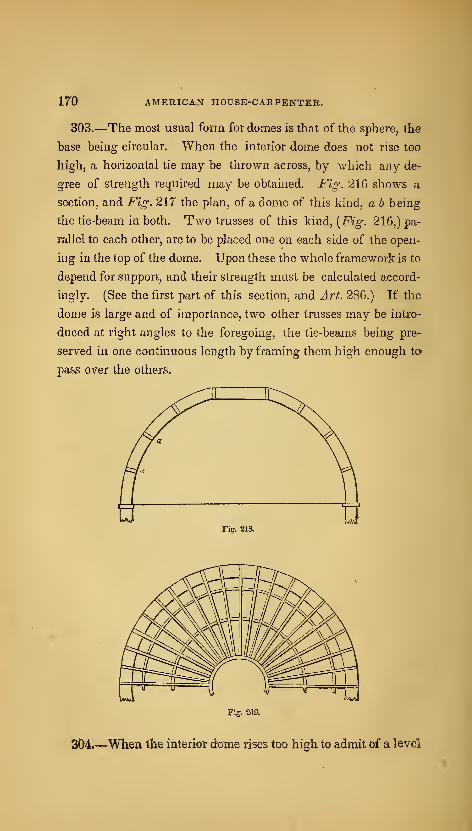
170 AMERICAN HOUSE-CARPENTER.
303.—The most usual form for domes is that of the sphere, the
base being circular. When the interior dome does not rise too
high, a horizontal tie may be thrown across, by which any de-
gree of strength required may be obtained. Fig. 216 shows a
section, and Fig. 217 the plan, of a dome of this kind, a h being
the tie-beam in both. Two trusses of this kind, {Fig. 216,) pa-
rallel to each other, are to be placed one on each side of the open-
ing in the top of the dome. Upon these the whole framework is to
depend for support, and their strength must be calculated accord-
ingly. (See the first part of this section, and Art. 286.) If the
dome is large and of importance, two other trusses may be intro-
duced at right angles to the foregoing, the tie-beams being pre-
served in one continuous length by framing them high enough to-
pass over the others.
Fig. 2ia
Fij. 219.
304.—When the interior dome rises too high to admit of a level
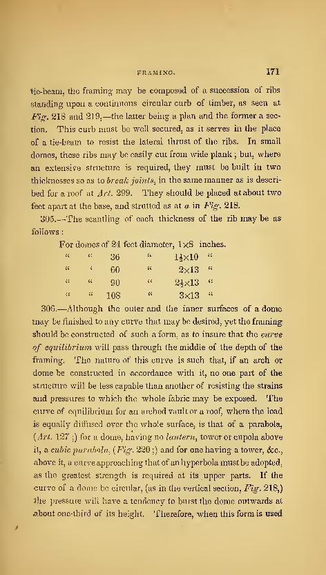
FRAMING. 171
tie-beam, the framing may be composed of a succession of ribs
standing upon a continuous circular curb of timber, as seen at
Fig-. 218 and 219,—the latter being a plan and the former a sec-
tion. This curb must be well secured, as it serves in the place
of a tie-beam to resist the lateral thrust of the ribs. In small
domes, these ribs may be easily cut from wide plank ; but, where
an extensive structure is required, they must be built in two
thicknesses so as to break joints, in the same manner as is descri-
bed for a roof at Art. 299. They should be placed at about two
feet apart at the base, and strutted as at a in Fig: 218.
305.—The scantling of each thickness of the rib may be as
follows
:
For domes of 24 feet diameter, 1x8 inches.
" '' 36 " 1^X10 "
" ' 60 " 2x13 "
" " 90 " 2|xl3 "
" " 108 " 3x13 "
306.—Although the outer and the inner surfaces of a dome
may be finished to any curve that may be desired, yet the framing
should be constructed of such a form, as to insure that the curve
of equilibrium will pass through the middle of the depth of the
framing. The nature of this curve is such that, if an arch or
dome be constructed in accordance with it, no one part of the
structure will be less capable than another of resisting the strains
and pressures to which the Avhole fabric may be exposed. The
curve of equilibrium for an arched vault or a roof, where the load
is equally diffused over the whole surface, is that of a parabola,
{Art. 127 ;) for a dome, having no lantern, tower or cupola above
it, a cubic parabola^ {F^S- ^^^ ?) ^^^^ ^''^^ one having a tower, <fcc.,
above it, a curve approaching that of an hyperbola must be adopted,
as the greatest strength is required at its upper parts. If the
curve of a dome be circular, (as in the vertical section, Fig. 218,)
the pressure will have a tendency to burst the dome outwards at
«3.bout one-third of its height. Therefore, when this form is used
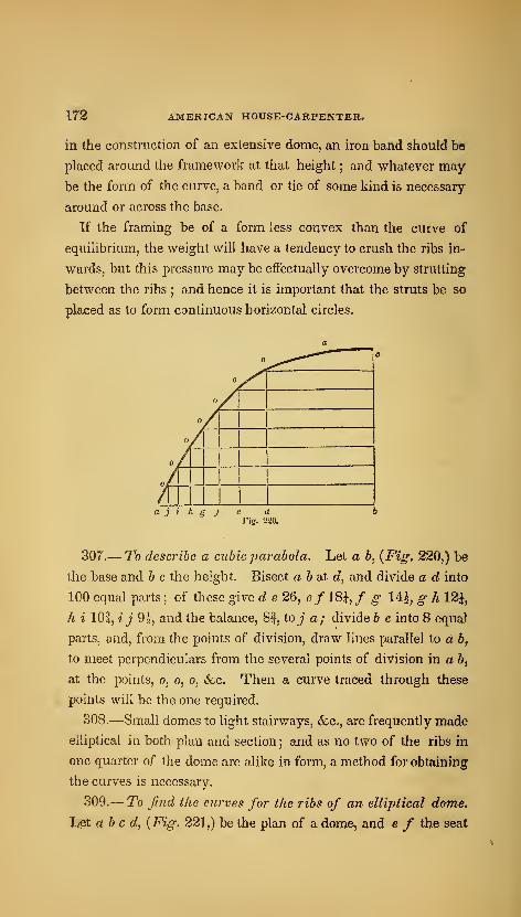
172 AMERICAN HOUSE-CARPENTER.
in the cotistmction of an extensive dome, an iron band should be
placed around the framework at that height ; and whatever may
be the form of the curve, a band or tie of some kind is necessary
around or across the base.
If the framing be of a form less convex than the curve of
equilibrium, the weight will have a tendency to crush the ribs in-
wards, but this pressure may be effectually overcome by strutting
between the ribs ; and hence it is important that the struts be so
placed as to form continuous horizontal circles.
307.— To describe a cubic parabola. Let a b, {Fig, 220,) be
the base and b c the height. Bisect a b at d, and divide a d into
100 equal parts; of these give d e 26, e/ 18^, / g 14|, g h 12^',
hi lOf, ij 9 J, and the balance, 8f, to j a; divide b c into 8 equal
parts, and, from the points of division, draw lines parallel to d b,
to meet perpendiculars from the several points of division in a b,
at the points, o, o, o, (fee. Then a curve traced through these
points will be the one required.
308.—Small domes to light stairways, &c., are frequently made
elliptical in both plan and section ; and as no two of the ribs in
one quarter of the dome are alike in form, a method for obtaining
the curves is necessary.
309.— To find the curves for the ribs of an elliptical dome.
Let abed, {Fig. 221,) be the plan of a dome, and e f the seat
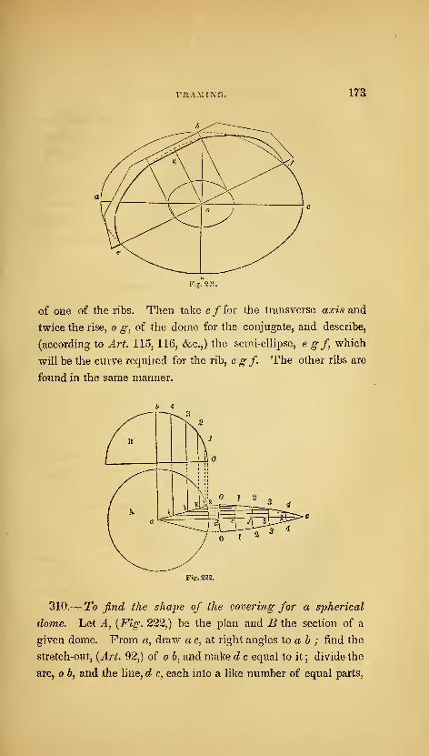
FJlAiMrNG. 173
of one of the ribs. Then take e/ for the transverse axis and
twice the rise, o g, of the dome for the conjugate, and describe,
(according to Art, 115, 116, &.c.,) the semi-ellipse, e g f^ which
will be the curve required for the rib, e g f. The other ribs are
found in the same manner.
Fig. 222.
310.— To find the shape of the covering for a spherical
dome. Let A^ {Fig. 222,) be the plan and B the section of a
given dome. From a, draw a c, at right angles to a b ; find the
stretch-out, {Art. 92,) of o b, and make d c equal to it ; divide the
arc, b, and the line, d c, each into a like number of equal parts,

174 AMERICAN HOUSE-CARPENTER.
as 5, (a large number will insure greater accuracy than a small
one ;) uponc, through the several points of division in c ri, describe
the arcs. odo,lel,2f2, &c. ; make d o equal to half the width
of one of the boards, and draw o s, parallel to a c ; join s and a,
and from the points of division in the arc, o b, drop perpendicu-
lars, meeting a s in ij k I ; from these points, draw i 4, j 3, &c.,
parallel to a c; make d o^ el, (fee, on the lower side of a c, equal
to c? 0, e 1, (fee, on the upper side ; trace a curve through the
points, 0, 1, 2, 3, 4, c, on each side of c^ c ; then o c o will be
the proper shape for the board. By dividing the circumference of
the base. A, into equal parts, and making the bottom, o d o,of the
board of a size equal to one of those parts, every board may be
made of the same size. In the same manner as the above, the
shape of the covering for sections of another form may be found,
such as an ogee, cove, &c.
311.— To find the curve of the hoards when laid in horizon-
tal courses. Let ABC, {Fig. 223,) be the section of a given
dome, and D B its axis. Divide B C into as many parts as
there are to be courses of boards, in the points, 1, 2, 3, &c.
;
through 1 and 2, draw a line to meet the axis extended at a ;
then a will be the centre for describing the edges of the board, E.
Through 3 and 2, draw 3 b ; tlien b will be the centre for describing
F. Through 4 and 3, draw Ad; then d will be the centre for G.
B is the centre for the arc, 1 o. If this method is taken to find
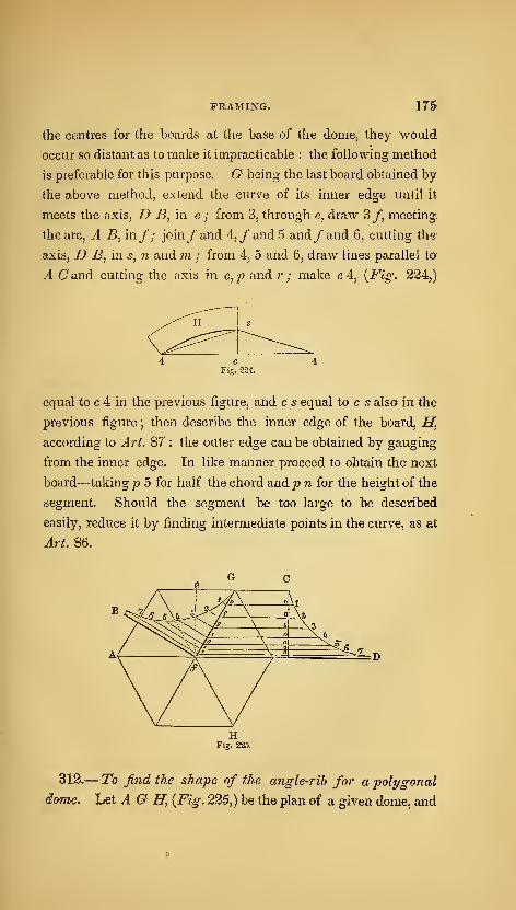
FRAMING. 175
the centres for the boards at the base of the dome, they would
occur so distant as to make it impracticable : the following method
is preferable for this purpose. G being the last board obtained by
the above method, extend the curve of its inner edge until it
meets the axis, D B, in. e ; from 3, through e, draw 3f, meeting:
the arc, A B, in/; join/and 4,/and5 and/and 6, cutting the
axis, D B, in s, n and 'm ; from 4, 5 and 6, draw lines parallel to
A C and cutting the axis in c, /j and r ; make c 4, {Fig. 224^)
equal to c 4 in the previous figure, and c s equal to c s also in the
previous figure ; then describe the inner edge of the board, H}
according to Art. 87 : the outer edge can be obtained by gauging
from the inner edge. In like manner proceed to obtain the next
board—taking p 5 for half the chord and p n for the height of the
segment. Should the segment be too large to be described
easily, reduce it by finding intermediate points in the curve, as at
Art. 86.
312.— To find the shape of the angle-rib for a polygonal
dome, het AG Hy {Fig. 225,) be the plan of a given dome, and
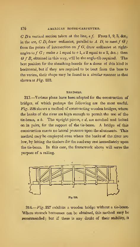
176 AMERICAN HOUSE-CARPENTEH.
C Da vertical section taken at the line^ ef. From 1, 2, 3, (fee,
in the arc, C D, draw ordinates, parallel to A D, to meet/ G ;
from the points of intersection on / G, draw ordinates at right-
angles to/ G ; make 5 1 equal to o 1, s 2 equal to o 2, (fee. ; then
GfB, obtained in this way, will be the angle-rib required. The
best position for the sheathing-boards for a dome of this kind is
horizontal, but if they are required to be bent from the base to
the vertex, their shape may be found in a similar manner to that
shown at Fig. 222.
BRIDGES.
313.—Various plans have been adopted for the construction of
bridges, of which perhaps the following are the most useful.
Fig. 226 shows a method of constructing wooden bridges, where
the banks of the river are high enough to permit the use of the
tie-beam, a h. The upright pieces, c d, are notched and bolted
on in pairs, for the support of the tie-beam. A bridge of this
construction exerts no lateral pressure upon the abutments. This
method may be employed even where the banks of the river are
low, by letting the timbers for the roadway rest immediately upon
the tie-beam. In this case, the framework above will serve the
purpose of a railing.
Fig. 226.
314.—Fig. 227 exhibits a wooden bridge without a tie-beani*
Where staunch buttresses can be obtained, this method may be
recommended ;but if there is any doubt of their stability, it
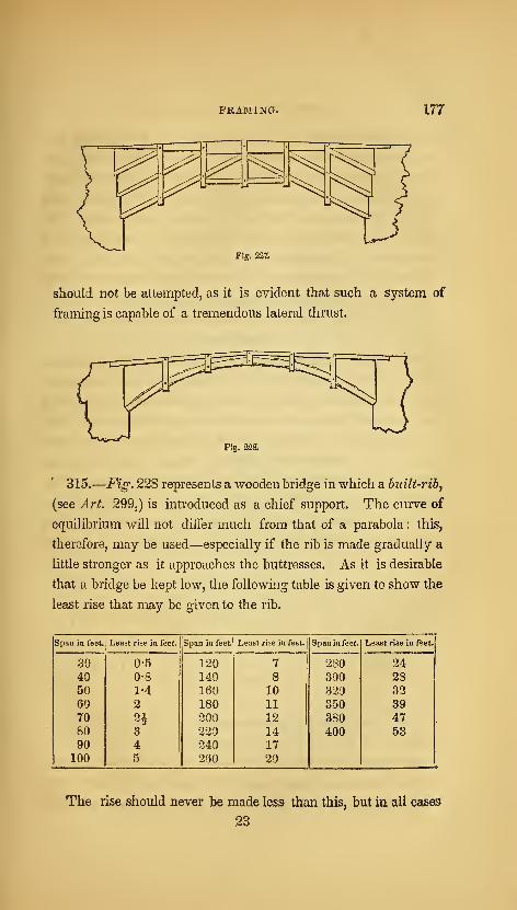
FRAMING. 177
Fig. 227.
should not be attempted, as it is evident that such a system of
framing is capable of a tremendous lateral thrust.
Fig. 228.
315.
—
Fig. 228 represents a wooden bridge in which a builf-rib,
(see Art. 299,) is introduced as a chief support. The curve of
equilibrium v\rill not differ much from that of a parabola : this,
therefore, may be used—especially if the rib is made gradually a
little stronger as it approaches the buttresses. As it is desirable
that a bridge be kept low, the following table is given to show the
least rise that may be given to the rib.
Span in feet. Least rise in feet. Span in feet. Least rise in feet. Span in feet. Least rise in feet.
39 0-5 120 7 280 2440 0-8 140 8 300 2350 1-4 160 10 320 3260 2 180 11 350 3970 n 200 12 380 4780 3 220 14 400 5390 4 240 17
100 51
260 20
The rise should never be made less than this, but in all cases
23
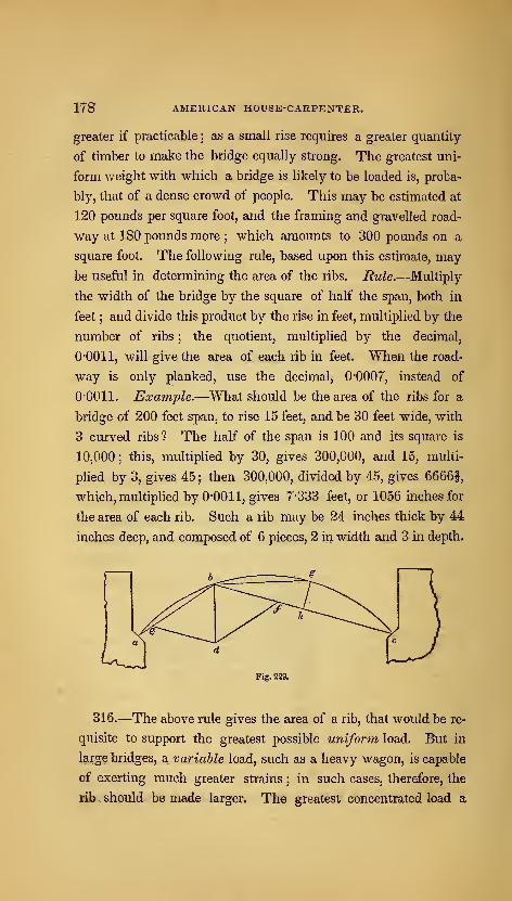
178 AMERICAN HOUSE-CARPENTER.
greater if practicable ; as a small rise requires a greater quantity
of timber to make the bridge equally strong. The greatest uni-
form weight with which a bridge is likely to be loaded is, proba-
bly, that of a dense crowd of people. This may be estimated at
120 pounds per square foot, and the framing and gravelled road-
way at 180 pounds more ; which amounts to 300 pounds on a
square foot. The following rule, based upon this estimate, may
be useful in determining the area of the ribs. Rule.—Multiply
the width of the bridge by the square of half the span, both in
feet ; and divide this product by the rise in feet, multiplied by the
number of ribs ; the quotient, multiplied by the decimal,
O'OOll, will give the area of each rib in feet. When the road-
way is only planked, use the decimal, 0*0007, instead of
O'OOll. Example.—What should be the area of the ribs for a
bridge of 200 feet span, to rise 15 feet, and be 30 feet wide, with
3 curved ribs 7 The half of the span is 100 and its square is
10,000 ; this, multiplied by 30, gives 300,000, and 15, multi-
plied by 3, gives 45 j then 300,000, divided by 45, gives 6666|,
which, multiplied by 0-0011, gives 7-333 feet, or 1056 inches for
the area of each rib. Such a rib may be 24 inches thick by 44
inches deep, and composed of 6 pieces, 2 in width and 3 in depth.
316.—The above rule gives the area of a rib, that would be re-
quisite to support the greatest possible uniform load. But in
large bridges, a, variable load, such as a heavy wagon, is capable
of exerting much greater strains ; in such cases, therefore, the
rib should be made larger. The greatest concentrated load a

FRAMING. 179
bridge will be likely to encounter, may be estimated at from about
20 to 50 thousand pounds, according to the size of the bridge.
This is capable of exerting the greatest strain, when placed at
about one-third of the span from one of the abutments, as at b,
{Fig. 229.) The weakest point of the segment, b g €^ is at g,
the most distant point from the chord line. The pressure exerted
at b by the above weight, may be considered to be in the direction
of the chord lines, b a and be; then, by constructing the paral-
lelogram of forces, e bf d, according to Art. 248, b f will show
the pressure in the direction, b c. Then the scantling for the rib
may be found by the following rule.
Rule.—Multiply the pressure in pounds in the direction, b c,
by the decimal, 0*0016, for white pine, 0"0021 for pitch pine, and
0"0015 for oak, and the product by the decimal representing the
sine of the angle, g b h, to a radius of unity. Divide this pro-
duct by the urfited breadth in inches of the several ribs, and the
cube-root of the quotient, multiplied by the distance, b c, in feet,
will give the depth of the rib. Example.—In a bridge of 200
feet span, 15 feet rise, having 3 ribs each 24 inches thick, or 72
inches whole thickness, the pressure in the direction, b c, is found
to be 166,000 lbs., and the sine of the angle, g b h, is 0*1—what
should be the depth of the rib for white pine? 166,000, mul-
tiplied by 0-0016, gives 265-6, which, multiplied by 0*1, gives
26-56;
this, divided by 72, gives 0-3689. The cube-root of the
last sum is 0-717 nearly, and the distance, b c, is 135 feet: then,
0-717, multiplied by 135, gives 96| inches, the depth required.
By this, each rib will require to be 24x97 inches, in order to en-
counter without injury the greatest possible load.
317.—In constructing these ribs, if the span be not over 50
feet, each rib may be made in two or three thicknesses of timber,
(three thicknesses is preferable,) of convenient lengths bolted
together ; but, in larger spans, where the rib will be such as to
render it difficult to procure timber of sufficient breadth, they
may be constructed by bending the pieces to the proper curve,

180 AMERICAN HOUSE-CARPENTER.
and bolting them together. In this case, wliere timber of suffi-
cient length to span the opening cannot be obtained, and scarfing
is necessary, such joints must be made as will resist both tension
and compression, (see Fig. 238.) To ascertain the greatest depth
for the pieces which compose the rib, so that the process of bend,
ing may not injure their elasticity, multiply the radius of curvature
in feet by the decimal, 0*05, and the product will be the depth in
inches. Example.—Suppose the curve of the rib to be described
with a radius of 100 feet, then what should be the depth ? The
radius in feet, 100, multiplied by 0'05, gives a product of 5 inches.
White pine or oak timber, 5 inches thick, would freely bend to
the above curve;and, if the required depth of such a rib be 20
inches, it would have to be composed of at least 4 pieces. Pitch
pine is not quite so elastic as white pine or oak—its thickness
may be found by using the decimal, 0-046, instead of 0-05.
Fig. 230.
318.—When the span is over 250 feet, b.framed rib, formed as
in Fig. 230, would be preferable to the foregoing. Of this, the
upper and the lower edges are formed as just described, by bend-
ing the timber to the proper curve. The pieces that tend to the
centre of the curve, called radials, are notched and bolted on in
pairs, and the cross-braces are halved together in the middle, and
abut end to end between the radials. The distance between the
ribs of a bridge should not exceed about 8 feet. The roadway

FRAMING. 181
should be supported by vertical standards bolted to the ribs at
about every 10 to 15 feet. At the place where they rest on the
ribSj a double, horizontal tie should be notched and bolted on the
back of the ribs, and also another on the under side ; and diago-
nal braces should be framed between the standards, over the space
between the ribs, to prevent lateral motion. The timbers for the
roadway may be as light as their situation will admit, as all use-
less timber is only an unnecessary load upon the arch.
319.—It is found that if a roadway be 18 feet wide, tAvo car-
riages can pass one another without inconvenience. Its width,
therefore, should be either 9, 18, 27 or 36 feet, according to the
amount of travel. The width of the foot-path should be 2 feet
for every person. When a stream of water has a rapid current,
as few piers as practicable should be allowed to obstruct its
course;otherwise the bridge will be liable to be swept away by
freshets. When the span is not over 300 feet, and the banks of
the river are of sufficient height to admit of it, only one arch
should be employed. The rise of the arch is limited by the form
of the roadway, and by the height of the banks of the river.
(See Art. 315.) The rise of the roadway should not exceed one
in 24 feet, but, as the framing settles about one in 72, the roadway
should be framed to rise one in 18, that it may be one in 24 after
settling. The commencement of the arch at the abutments—the
spri7ig, as it is termed, should not be below high-water mark :
and the bridge should be placed at right angles with the course of
the current.
320.—The best material for the abutments and piers of a
bridge, is stone ; and, if possible, stone should be procured for the
purpose. The following rule is to determine the extent of the
abutments, they being rectangular, and built with stone weighing
120 lbs. to a cubic-foot. Rule.—Multiply the square of the
height of the abutment by 160, and divide this product by the
weight of a square foot of the arch, and by the rise of the arch;
add unity to the quotient, and extract the square-root. Diminish
the square-root by unity, ,and multiply the root, so diminished, by

182 AMERICAN HOUSE-CARPENTER.
half the span of the arch, and by the weight of a square-foot of
the arch. Divide the last product by 120 times the height of the
abutment, and the quotient will be the thickness of the abutment.
Example.—Let the height of the abutment from the base to the
springing of the arch be 20 feet, half the span 100 feet, the weight
of a square foot of the arch, including the greatest possible load
upon it, 300 pounds, and the rise of the arch 18 feet—what should
be its thickness ? The square of the height of the abutment,
400, multiplied by 160, gives 64,000, and 300 by 18, gives 5400
;
64,000, divided by 5400, gives a quotient of 11*852, one added to
this makes 12'852, the square-root of which is 3'6; this, less one,
is 2*6 ; this, multiplied by 100, gives 260, and this again by 300,
gives 78,000 ; this, divided by 120 times the height of the abut-
ment, 2400, gives 32 feet 6 inches, the thickness required.
The dimensions of a pier will be found by the same rule.
For, although the thrust of an arch may be balanced by an ad-
joining arch, when the bridge is finished, and while it remains
uninjured;yet, during the erection, and in the event of one arch
being destroyed, the pier should be capable of sustaining the en-
tire thrust of the other.
321.—Piers are sometimes constructed of timber, their princi-
pal strength depending on piles driven into the earth, but such
piers should never be adopted where it is possible to avoid them
;
for, being alternately wet and dry, they decay much sooner than
the upper parts of the bridge. Spruce and elm are considered
good for piles. Where the height from the bottom of the
river to the roadway is great, it is a good plan to cut them off at
a little below low-water mark, cap them with a horizontal tie,
and upon this erect the posts for the support of the roadway.
This method cuts off the part that is continually wet from that
which is only occasionally so, and thus affords an opportunity for
replacing the upper part. The pieces which are immersed will
last a great length of time, especially when of elm ; for it is a
well-established fact, that timber is less durable when subject to
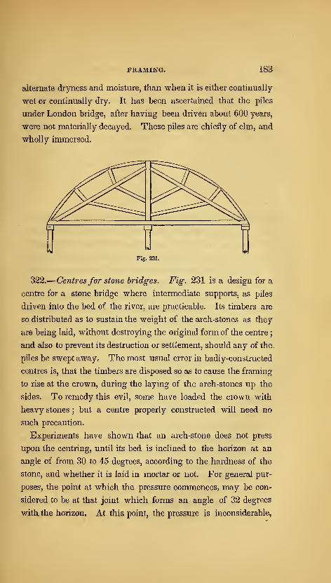
FRAMING. 183
alternate dryness and moisture, than when it is either continually-
wet or continually dry. It has been ascertained that the piles
under London bridge, after having been driven about 600 years,
were not materially decayed. These piles are chiefly of elm, and
wholly immersed.
Fig. 231.
322.
—
Centresfor stone bridges. Fig. 231 is a design for a
centre for a stone bridge where intermediate supports, as piles
driven into the bed of the river, are practicable. Its timbers are
so distributed as to sustain the weight of the arch-stones as they
are being laid, without destroying the original form of the centre
;
and also to prevent its destruction or settlement, should any of the
piles be swept away. The most usual error in badly-constructed
centres is, that the timbers are disposed so as to cause the framing
to rise at the crown, during the laying of the arch-stones up the
sides. To remedy this evil, some have loaded the crown with
heavy stones ; but a centre properly constructed will need no
such precaution.
Experiments have shown that an arch-stone does not press
upon the centring, until its bed is inclined to the horizon at an
angle of from 30 to 45 degrees, according to the hardness of the
stone, and whether it is laid in mortar or not. For general pur-
poses, the point at which the pressure commences, may be con-
sidered to be at that joint which forms an angle of 32 degrees
with the horizon. At this point, the pressure is inconsiderable.
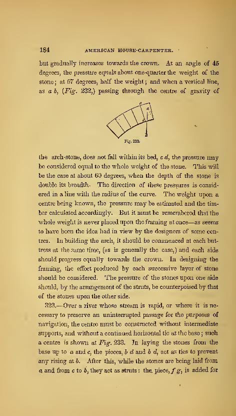
184 AMERICAN HOUSE-CARPENTER. '
but gradually increases towards the crown. At an angle of 45
degrees, the pressure equals about one-quarter the weight of the
stone ; at 57 degrees, half the weight ; and when a vertical line,
as a b, {Fig. 232,) passing through the centre of gravity of
Fig. 232.
the arch-stone, does not fall within its bed, c d, the pressure may
be considered equal to the whole weight of the stone. This will
be the case at about 60 degrees, when the depth of the stone is
double its breadth. The direction of these pressures is consid-
ered in a line with the radius of the curve. The weight upon a
centre being known, the pressure may be estimated and the tim-
ber calculated accordingly. But it must be remembered that the
whole weight is never placed upon the framing at once—as seems
to have been the idea had in view by the designers of some cen-
tres. In building the arch, it should be commenced at each but-
tress at the same time, (as is generally the case,) and each side
should progress equally towards the crown. In designing the
framing, the effect produced by each successive layer of stone
should be considered. The pressure of the stones upon one side
should, by the arrangement of the struts, be counterpoised by that
of the stones upon the other side.
323.—Over a river whose stream is rapid, or where it is ne-
cessary to preserve an uninterrupted passage for the purposes of
navigation, the centre must be constructed without intermediate
supports, and without a continued horizontal tie at the base ; such
a centre is shown at Fig. 233. In laying the stones from the
base up to a and c, the pieces, b d and b d, act as ties to prevent
any rising at b. After this, while the stones are being laid from
a and from c to &, they act as struts : the, piece, /^, is added for

185
Fig. 233.
additional security. Upon this plan, with some variation to suit
circumstances, centres may be constructed for any span usual in
stone-bridge building.
324.—In bridge centres, the principal timbers should abut, and
not be intercepted by a suspension or radial piece between.
These should be in halves, notched on each side and bolted.
The timbers should intersect as little as possible, for the more
joints the greater is the settling ; and halving them together is a
bad practice, as it destroys nearly one-half the strength of the
timber. Ties should be introduced across, especially where many
timbers meet ; and as the centre is to serve but a temporary pur-
pose, the whole should be designed with a view to employ the
timber afterwards for other uses. For this reason, all unneces-
sary cutting should be avoided.
325.—Centres should be sufficiently strong to preserve a
staunch and steady form during the whole process of building
;
for any shaking or trembling will have a tendency to prevent the
mortar or cement from setting. For this purpose, also, the cen-
tre should be lowered a trifle immediately after the key-stone is
laid, in order that the stones may take their bearing before the
mortar is set ; otherwise the joints will open on the under side.
The trusses, in centring, are placed at the distance of from 4 to
6 feet apart, according to their strength and the weight of the
24

186 AMERICAN HOUSE-CARPENTER.
arch. Between every two trusses, diagonal braces should be in-
troduced to prevent lateral motion.
326.—In order that the centre maybe easily lowered, the frames,
or trusses, should be placed upon wedge-formed sills; as is shown
at d, {Fig. 233.) These are contrived so as to admit of the settling
of the frame by driving the wedge, d, with a maul, or, in large
centres, a piece of timber mounted as a battering-ram. Theoperation of lowering a centre should be very slowly performed,
in order that the parts of the arch may take their bearing uni-
formly. The wedge pieces, instead of being placed parallel with
the truss, are sometimes made sufficiently long and laid through
the arch, in a direction at right angles to that shown at Fig. 233.
This method obviates the necessity of stationing men beneath the
arch during the process of lowering ; and was originally adopted
with success soon after the occurrence of an accident, in lower-
ing a centre, by which nine men were killed.
327.—To give some idea of the manner of estimating the
pressures, in order to select timber of the proper scantling, calcu-
late the pressure of the arch-stones from i to b, {Fig. 233,) and
suppose half this pressure concentrated at a, and acting in the
direction, a f. Then, by reference to the laws of pressure and
the resistance of timber at Art. 248, 260, &c., the scantlings of
the several pieces composing the frame, b d a, may be computed.
Again, calculate the pressure of that portion of the arch included
between a and c, and consider half of it collected at b, and acting
in a vertical direction ; then the amount of pressure on the beams,
b d and b d, may be found by reference to the first part of this
section, as above. Add the pressure of that portion of the arch
which is included between i and b to half the weight of the cen-
tre, and consider this amount concentrated at d, and acting in a
vertical direction \ then, by constructing the parallelogram of
forces, the pressure upon dj may be ascertained.
328.—As a short rule for calculating the scantlings of the tim-
bers, let every strut be suffi.ciently braced, so that it will yield to

FRAMING. 18T
crushing before it will bendunder the pressure
—
{Art. 261.) Then
divide the pressure in pounds by 1000, and the quotient will be
the area of the strut in inches. For example, let the pressure
upon a strut, in the direction of its eixis, be 60,000 lbs. This,
divided by 1000, gives 60, the area of the strut in inches ; the
size of the strut, therefore, might be 6x10. This rule is based
upon experiments by which it has been ascertained, that 1000
pounds is the greatest load that can be trusted upon a square inch
of timber, without more indentation than would be compatible
with the stability of the framing. The area ascertained by the
rule, therefore, must have reference to the actual amount of sur-
face upon which the load bears ; and should the strut have a tenon
on the end, the area of the shoulders, instead of a section of the
whole piece, must be equal to the amount given by the rule.
329.—In the construction of arches, the voussoirs, or arch-
stones, are so shaped that the joints between them are perpen-
dicular to the curve of the arch, or to its tangent at the point at
which the joint intersects the curve. In a circular arch, the
joints tend toward the centre of the circle : in an elliptical
arch, the joints may be found by the following process :
/ Fig. 234. /
330.— To find the direction of the joints for an elliptical
arch. A joint being wanted at a, {Fig. 234,) draw lines from
that point to the foci, /and/; bisect the angle, /a/, with the
line, ab ; then a b will be the direction of the joint.
331.— To find the direction of thejointsfor a parabolic arch.
A joint being wanted at a, {Fig. 235,) draw a e, at right angles to
the axis, eg; make c g equal to c e, and join a and g ; draw a h, at
right angles toa g ; then a h will be the direction of the joint.
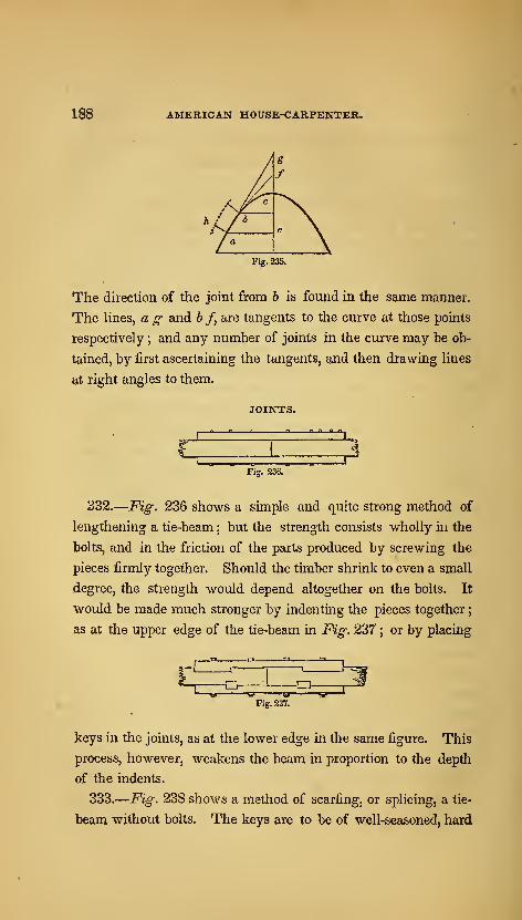
188 AMERICAN HOUSE-CARPENTER.
a/^
g
f
hl/6• \
/ ^ \Fig. 235.
The direction of the joint from h is found in the same manner.
The lines, a g and h /, are tangents to the curve at those points
respectively ; and any number of joints in the curve may be ob-
tained, by first ascertaining the tangents, and then drawing lines
at right angles to them.
JOINTS.
1 1
1 41 1
Fig. 236.
332.
—
Fig, 236 shows a simple and quite strong method of
lengthening a tie-beam ; but the strength consists wholly in the
bolts, and in the friction of the parts produced by screwing the
pieces firmly together. Should the timber shrink to even a small
degree, the strength would depend altogether on the bolts. It
would be made much stronger by indenting the pieces together
;
as at the upper edge of the tie-beam in Fig. 237 ; or by placing
e5^ -oFig. 237.
keys in the joints, as at the lower edge in the same figure. This
process, however, weakens the beam in proportion to the depth
of the indents.
333.
—
Fig. 238 shows a method of scarfing, or splicing, a tie-
beam without bolts. The keys are to be of well-seasoned, hard

FRAMING. • 189
-O-
Fig. 233.
wood, and, if possible, very cross-grained. The addition of bolts
would make this a very strong splice, or even white-oak pins
would add materially to its strength.
Fig. 239.
334.
—
Fig. 239 shows about as strong a splice, perhaps, as
can well be made. It is to be recommended for its simplicity
;
as, on account of their being no oblique joints in it, it can be
readily and accurately executed. A complicated joint is the
worst that can be adopted ; still, some have proposed joints that
seem to have little else besides complication to recommend
them.
335.—^In proportioning the parts of these scarfs, the depths of
all the indents taken together should be equal to one-third of the
depth of the beam. In oak, ash or elm, the whole length of the
scarf should be six times the depth, or thickness, of the beam,
when there are no bolts ; but, if bolts instead of indents are used,
then three times the breadth ; and, when both methods are com-
bined, twice the depth of the beam. The length of the scarf in
pine and similar soft woods, depending wholly on indents, should
be about 12 times the thickness, or depth, of the beam ; when
depending wholly on bolts, 6 times the breadth ; and, when both
methods are combined, 4 times the depth.
Fig. 240.
336.—Sometimes beams have to be pieced that are required to
resist cross strains—such as a girder, or the tie-beam of a roof
when supporting the ceiling. In such beams, the fibres of the
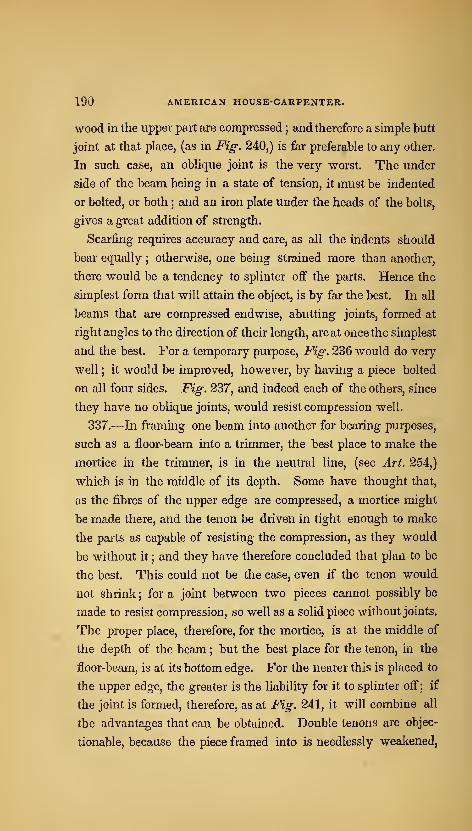
190 AMERICAN HOUSE-CARPENTER.
wood in the upper part are compressed ; and therefore a simple butt
joint at that place, (as in Fig. 240,) is far preferable to any other.
In such case, an oblique joint is the very worst. The under
side of the beam being in a state of tension, it must be indented
or bolted, or both ; and an iron plate under the heads of the bolts,
gives a great addition of strength.
Scarfing requires accuracy and care, as all the indents should
bear equally; otherwise, one being strained more than another,
there would be a tendency to splinter off the parts. Hence the
simplest form that will attain the object, is by far the best. In all
beams that are compressed endwise, abutting joints, formed at
right angles to the direction of their length, are at once the simplest
and the best. For a temporary purpose. Fig. 236 would do very
well ; it would be improved, however, by having a piece bolted
on all four sides. Fig. 237, and indeed each of the others, since
they have no oblique joints, would resist compression well.
337.—In framing one beam into another for bearing purposes,
such as a floor-beam into a trimmer, the best place to make the
mortice in the trimmer, is in the neutral line, (see Art. 254,)
which is in the middle of its depth. Some have thought that,
as the fibres of the upper edge are compressed, a mortice might
be made there, and the tenon be driven in tight enough to make
the parts as capable of resisting the compression, as they would
be without it ; and they have therefore concluded that plan to be
the best. This could not be the case, even if the tenon would
not shrink ; for a joint between two pieces cannot possibly be
made to resist compression, so well as a solid piece without joints.
The proper place, therefore, for the mortice, is at the middle of
the depth of the beam ; but the best place for the tenon, in the
floor-beam, is at its bottom edge. For the nearer this is placed to
the upper edge, the greater is the liability for it to splinter off; if
the joint is formed, therefore, as at Fig. 241, it will combine all
the advantages that can be obtained. Double tenons are objec-
tionable, because the piece framed into is needlessly weakened,
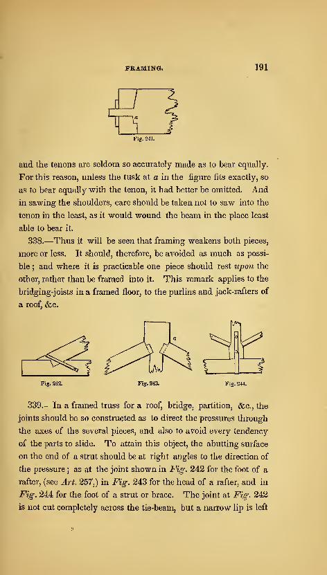
FRAMING. 191
oFig. 241.
and the tenons are seldom so accurately made as to bear equally.
For this reason, unless the tusk at a in the figure fits exactly, so
as to bear equally with the tenon, it had better be omitted. And
in sawing the shoulders, care should be taken not to saw into the
tenon in the least, as it would wound the beam in the place least
able to bear it.
338.—Thus it will be seen that framing weakens both pieces,
more or less. It should, therefore, be avoided as much as possi-
ble ; and where it is practicable one piece should rest upon the
other, rather than be framed into it. This remark applies to the
bridging-joists in a framed floor, to the purlins and jack-rafters of
a roof, &c.
Fig. 242. Fig. 243.
339.—In a framed truss for a roof, bridge, partition, &c., the
joints should be so constructed as to direct the pressures through
the axes of the several pieces, and also to avoid every tendency
of the parts to slide. To attain this object, the abutting surface
on the end of a strut should be at right angles to the direction of
the pressure ; as at the joint shown in Fig. 242 for the foot of a
rafter, (see Art. 257,) in Fig. 243 for the head of a rafter, and in
Fig. 244 for the foot of a strut or brace. The joint at Fig. 242
is not cut completely across the tie-beam, but a narrow lip is left
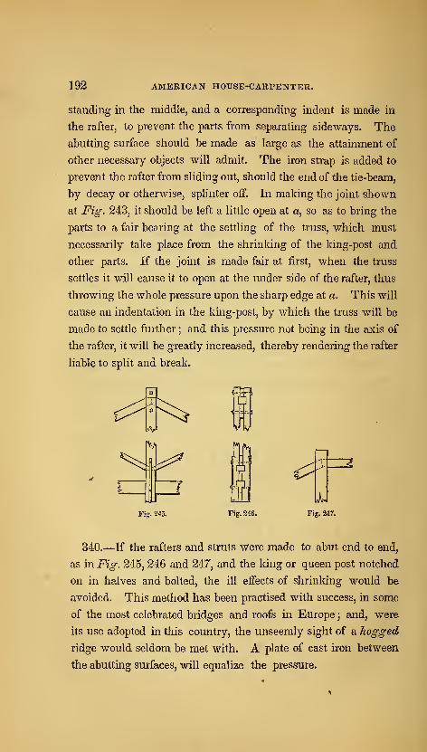
192 AMERICAN HOUSE-CARPENTER.
Standing in the middle, and a corresponding indent is made in
the rafter, to prevent the parts from separating sideways. The
abutting surface should be made as large as the attainment of
other necessary objects will admit. The iron strap is added to
prevent the rafter from sliding out, should the end of the tie-beam,
by decay or otherwise, splinter off. In making the joint shown
at Fig. 243, it should be left a little open at a, so as to bring the
parts to a fair bearing at the settling of the truss, which must
necessarily take place from the shrinking of the king-post and
other parts. If the joint is made fair at first, when the truss
settles it will cause it to open at the under side of the rafter, thus
throwing the whole pressure upon the sharp edge at a. This will
cause an indentation in the king-post, by which the truss will be
made to settle further ; and this pressure not being in the axis of
the rafter, it will be greatly increased, thereby rendering the rafter
liable to split and break.
<^'
Fig. 245. Fig. 246. Fig. 247.
340.—If the rafters and struts w'ere made to abut end to end,
as in Fig. 245, 246 and 247, and the king or queen post notched
on in halves and bolted, the ill effects of shrinking would be
avoided. This method has been practised with success, in some
of the most celebrated bridges and roofs in Europe ; and, were
its use adopted in this country, the unseemly sight of a hogged
ridge would seldom be met with. A plate of cast iron between
the abutting surfaces, will equalize the pressure.
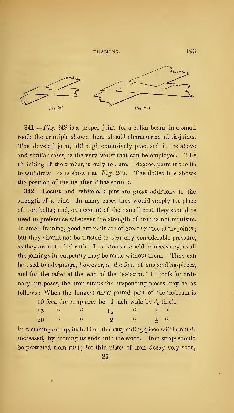
tRAMimai 193
Fig. 24S. Fig. 249;
341.
—
Fig. 248 is a proper joint for a coUar^beam in a small
roof: the principle shown here should characterize all tie-joints,
^he dovetail joint, although extensively practised in the above
and similar cases, is the very Avorst that can be employed. The
shrinking of the timber^ if only to a small degree, permits the tie
to withdraw—as is shown at Fig. 249. The dotted line shows
the position of the tie after it has shrunk.
342.^—-Locust and white-oak pins are great additions to the
strength of a joint. In many casesj they would supply the place
of iron bolts; and, on account of their small cost, they should be
used in preference wherever the strength of iron is not requisite.
In small framing, good cut nails are of great service at the joints;
but they should not be trusted to bear any considerable pressure,
as they are apt to be brittle. Iron straps are seldom necessary, as all
the joinings in carpentry may be made without them. They can
be used to advantage, however, at the foot of suspending-pieces,
and for the rafter at the end of the tie-beam. ' In roofs for ordi-
nary purposes, the iron straps for suspending-pieces may be as
follows : When the longest unsupported part of the tie-beam is
10 feet, the strap may be 1 inch wide by j\ thick.
15 1.
20 " " 2 "i "
In fastening a strap, its hold on the suspending-piece will be much
increased, by turning its ends into the wood. Iron straps should
be protected from rust ; for thin plates of iron decay very soon,
25
194 AMERICAN HOUSE-CARPENTER.
especially when exposed to dampness. For this purpose, as so<5n
as the strap is made, let it be heated to about a blue heat, and,
while it is hot, pour over its entire surface raw linseed oil, or rub
it with beeswax. Either of these will give it a coating which
dampness will not penetrate.

SECTION v.—DOORS, WINDOWS, &c.
DOORS.
343.—Among the several architectural arrangements of an edi-
fice, the door is by no means the least in importance ; and, if pro-
perly constructed, it is not only an article of use, but also of or-
nament, adding materially to the regularity and elegance of the
apartments. The dimensions and style of finish of a door, should
be in accordance with the size and style of the building, or the
apartment for which it is designed. As regards the utility of
doors, the principal door to a public building should be of suffi-
cient width to admit of a free passage for a crowd of people
;
while that of a private apartment will be wide enough, if it per-
mit one person to pass without being incommoded. Experience
has determined that the least width allowable for this is 2 feet 8
inches ; although doors leading to inferior and unimportant rooms
may, if circumstances require it, be as narrow as 2 feet 6 inches
;
and doors for closets, where an entrance is seldom required, may
be but 2 feet wide. The width of the principal door to a public
building may be from 6 to 12 feet, according to the size of the
building; and the width of doors for a dwelling may be from 2
feet 8 inches, to 3 feet 6 inches. If the importance of an apart-
ment in a dwelling be such as to require a door of greater width
196 AMERICAN HOUSE-CARPENTER.
than 3 feet 6 inches, the opening should be closed with two
doors, or a door in two folds;generally, in such cases, where the
opening is from 5 to 8 feet, folding or sliding doors are adopted*
As to the height of a door, it should in no case be less than about
6 feet 3 inches ; and generally not less than 6 feet 8 inches.
344.—The proportion between the width and height of single
doors, for a dwelling, should be as 2 is to 5 ; and, for entrance-
doors to public buildings, as 1 is to 2. If the width is given and
the height required of a door for a dwelling, multiply the width
by 5, and divide the product by 2;but, if the height is given and
the width required, divide by 5, and multiply by 2. Where two
or more doors of diiferent widths show in the same room, it is
well to proportion the dimensions of the more important by the
above rule, and make the narrower doors of the same height as
the wider ones ; as all the doors in a suit of apartments, except
the folding or sliding doors, have the best appearance when of
one height. The proportions for folding or sliding doors should
be such that the width may be equal to | of the height;yet this
rule needs some qualification : for, if the width of the opening
be greater than one-half the width of the room, there will not be
a sufficient space left for opening the doors ; also, the height
should be about one4enth greater than that of the adjacent single
doors.
345.—Where doors have but two panels in width, let the stiles
and muntins be each 4 of the width ; or, whatever number of
panels there may be, let the united widths of the stiles and the
muntins, or the whole width of the solid, be equal to j of the width
of the door. Thus : in a door, 35 inches wide, containing two
panels in width, the stiles should be 5 inches wide ; and in a door,
3 feet 6 inches wide, the stiles should be 6 inches. If a door, 3
feet 6 inches wide, is to have 3 panels in width, the stiles and
muntins should be each 4^ inches wide, each panel being 8 inches.
The bottom rail and the lock rail ought to be each equal in
width to j\ of the height of the door ; and the top rail, and all
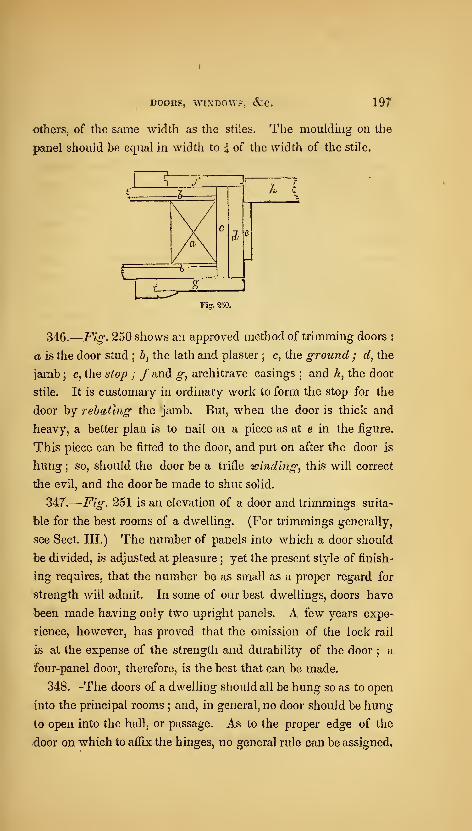
DOORS, WINDOW?, &C. 197
Others, of the same width as the stiles. The moulding on the
panel should be equal in width to i of the width of the stile.
U^346.
—
Fig. 250 shows an approved method of trimming doors :
a is the door stud ; b, the lath and plaster ; c, the ground ; d, the
jamb ; e, the stop ; /and g, architrave casings;and h, the door
stile. It is customary" in ordinary work to form the stop for the
door by rebating the jamb. But, when the door is thick and
heavyj a better plan is to nail on a piece as at e in the figure.
This piece can be fitted to the door, and put on after the door is
hung ;so, should the door be a trifle winding, this will correct
the evil, and the door be made to shut solid.
347.
—
Fig. 251 is an elevation of a door and trimmings suita-
ble for the best rooms of a dwelling. (For trimmings generally,
see Sect. III.) The number of panels into which a door should
be divided, is adjusted at pleasure;yet the present style of finish-
ing requires, that the number be as small as a proper regard for
strength will admit- In some of our best dwellings, doors have
been made having only two upright panels. A few years expe-
rience, however, has proved that the omission of the lock rail
is at the expense of the strength and durability of the door ; a
four-panel door, therefore, is the best that can be made.
348.—The doors of a dwelling should all be hung so as to open
into the principal rooms;and, in general, no door should be hung
to open into the hall, or passage. As to the proper edge of the
door on which to aflix the hinges, no general rule can be assigned,
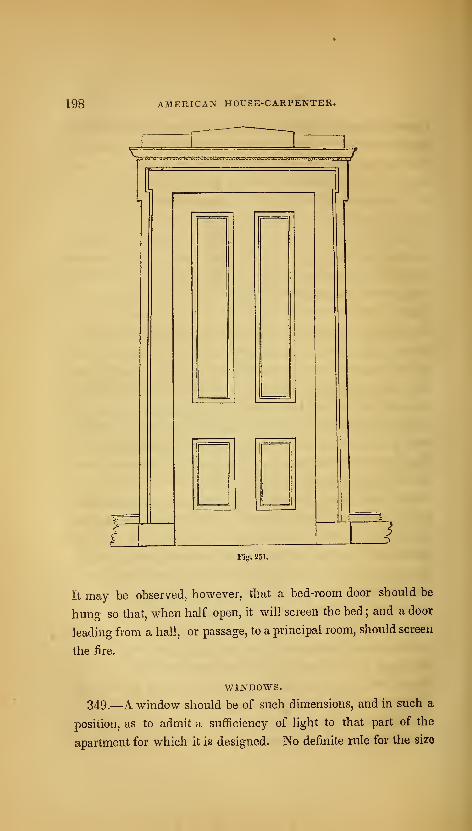
198 AMERICAN HOrSE-CARPENTER.
•ytlnmim.'-iwi'vM.'lv.- n^^i'.vnu/i'jll^l'
it
Fiff. 251.
It may be observed, however, that a bed-room door should be
huDg so that, when half open, it will screen the bed ; and a door
leading from a hall, or passage, to a principal room, should screen
the fire.
WINDOWS.
349.—A window should be of such dimensions, and in such a
position, as to admit a sufficiency of light to that part of the
apartment for which it is designed. No definite rule for the size

DOORS, WINDOWS, &C. 199
can well be given, that will answer in all cases;
yet, as an ap-
proximation, the following has been used for general purposes.
Multiply together the length and the breadth in feet of the apart-
ment to be lighted, and the product by the height in feet ; then
the square-root of this product will show the required number of
square feet of glass.
350.—To ascertain the dimensions of window frames, add Ah
inches to the width of the glass for their width, and 6-^ inches to
the height of the glass for their height. These give the dimen-
sions, in the clear, of ordinary frames for 12-light windows ; the
height being taken at the inside edge of the sill. In a brick wall,
the width of the opening is 8 inches more than the width of the
glass—4^ for the stiles of the sash, and 3J for banging stiles
—
and the height between the stone sill and lintel is about 101 inches
more than the height of the glass, it being varied according to the
thickness of the sill of the frame.
351.—In hanging inside shutters to fold into boxes, it is ne-
cessary to have the box shutter about one inch wider than the
flap, in order that the flap may not interfere when both are folded
into the box. The usual margin shown between the face of the
shutter when folded into the box and the quirk of the stop bead,
or edge of the casing, is half an inch ; and, in the usual method
of letting the w/2oZe of the thickness of the butt hinge into the
edge of the box shutter, it is necessary to make allowance for the
throw of the hinge. This may, in general, be estimated at \ of
an inch at each hinging ; which being added to the margin, the
entire width of the shutters will be lA inches more than the width
of the frame in the clear. Then, to ascertain the width of the
box shutter, add 1-| inches to the width of the frame in the clear,
between the pulley stiles ;divide this product by 4, and add
half an inch to the quotient ; and the last product will be the re-
quired width. For example, suppose the window to have 3
lights in width, 11 inches each. Then, 3 times 11 is 33, and A\
added for the wood of the sash, gives 37^ -37^ and 1^ is 39,
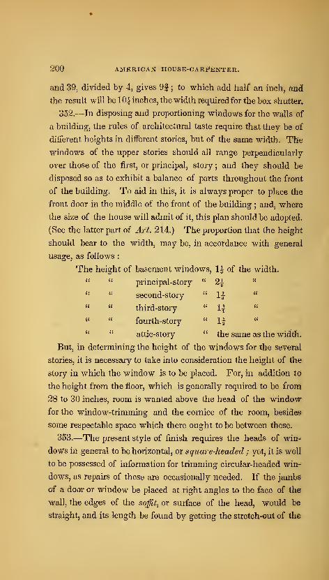
200 AMERICAN HOUSE-CARi*feNTER.
and 39, divided by 4, gives 9| ; to which add half an inch, arid
the result will be 10| inches, the width required for the box shutter.
352.—In disposing and proportioning windows for the walls of
a building, the rules of architectural taste require that they be of
different heights in different stories, but of the same width. The
windows of the upper stories should all range perpendicularly
over those of the fiist, or principal, story ; and they should be
disposed so as to exhibit a balance of parts throughout the front
of the building. To aid in this, it is always proper to place the
front door in the middle of the front of the building; and, where
the size of the house will admit of it, this plan should be adopted.
(See the latter part of Art. 214.) The proportion that the height
should bear to the width, may be, in accordance with general
usage, as follows :
The height of basement windows, 1^ of the width.
" " principal-story " 2^"
" " second-story " 1| "
" " third-story " 1| «
" " fourth-story " U "
" " attic-story " the same as the width.
But, in determining the height of the windows for the several
stories, it is necessary to take into consideration the height of the
story in which the window is to be placed. For, in addition to
the height from the floor, which is generally required to be froni
28 to 30 inches, room is wanted above the head of the window
for the window-trimming and the cornice of the room, besides
some respectable space which there ought to be between these.
353.—The' present style of finish requires the heads of win-
dows in general to be horizontal, or square-headed ; yet^ it is well
to be possessed of information for trimming circular-headed win-
dows, as repairs of these are occasionally needed. If the jambs'
of a door or window be placed at right angles to the face of the
wall, the edges of the soffit, or surface of the head, would be
straight, and its length be found by getting the stretch-out of the
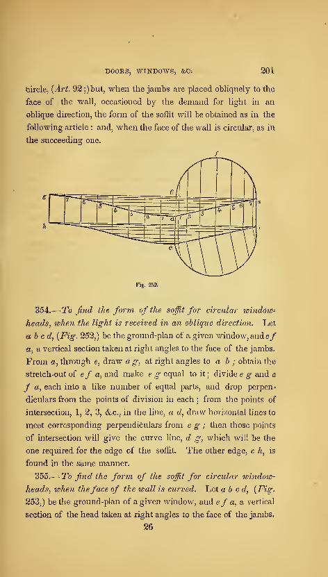
DOORS, WINDOWS, &C; 20t
fcirclej {Art. 92 ;)biit, when the jambs are placed obliquely to the
face of the wall, occasioned by the demand for light in an
oblique direction, the form of the solEt will be obtained as in the
following article : and, when the face of the wall is circular, as in
the succeeding one.
Fig. 252.
354.— To find the form of the soffit for circular windov)^
heads, when the light is received in an oblique direction. Let
abed, {Fig. 252,) be the ground-plan of a given window, and ef
a, a vertical section taken at right angles to the face of the jambs.
From a, through e, draw a g, at right angles to a b ; obtain the
Stretch-out of ef a^ and make e g equal to it ; divide e g and e
f a, each into a like number of equal parts, and drop perpen-
diculars from the points of division in each ; from the points of
intersection, 1, 2, 3, &c., in the line, a d, draw horizontal lines to
meet corresponding perpendiculars from eg; then those points
of intersection will give the curve line, d g, which will be the
one required for the edge of the soffit. The other edge, c A, is
found in the same manner.
355.—^ To find the form of the soffit for circular toindow
heads, when theface of the wall is curved. Let abed, [Fig.
253,) be the ground-plan of a given window, and ef a, a. vertical
section of the head taken at right angles to the face of the jambs.
26
202 AMERICAN HOUSE-CARPENTER.
Fig. 253. c
Proceed as in the foregoing article to obtain the line, d g ; then
that will be the curve required for the edge of the soffit ; the
other edge being found in the same manner.
If the given vertical section be taken in a line with the face of
the wall, instead of at right angles to the face of the jambs, place
it upon the line, c 6, {Fig. 252 ;) and, having drawn ordinates at
right angles to c 6, transfer them to ef a ; in this way, a section
at right angles to the jambs can be obtained.
SECTION YL—STAIRS.
356.—The stairs is that mechanical arrangement in a bfiild-
ing by which access is obtained from one story to another. Their
position, form and finish, when determined with discriminating
taste, add greatly to the comfort and elegance of a structure. As
regards their position, the first object should be to have them near
the middle of the building, in order that an equally easy access
may be obtained from all the rooms and passages. Next in im-
portance is light; to obtain which they would seem to be best
situated near an outer wall, in which windows might be construc-
ted for the purpose;yet a sky-light, or opening in the roof, would
not only provide light, and so secure a central position for the
stairs, but may be made, also, to assist materially as an ornament
to the building, and, what is of more importance, afford an op-
portunity for better ventilation.
357.—It would seem that the length of the raking side of the
pitch-board, or the distance from the top of one riser to the top of
the next, should be about the same in all cases;for, whether stairs
be intended for large buildings or for small, for public or for pri-
vate, the accommodation of men of the same stature is to be con-
sulted in every instance. But it is evident that, with the same
effort, a longer step can be taken on level than on rising ground
;

204 AMERICAN HOUSE-CARPENTER.
and that, although the tread and rise cannot be proportioned
merely in accordance with the style and importance of the build-
ing, yet this may be done according to the angle at which the
flight rises. If it is required to ascend gradually and easy, the
length from the top of one rise to that of another, or the hypothe-
nuse of tiie pitch-board, may be long ; but, if the flight is steep,
the length must be shorter. Upon this data the foliowiug problem
is constructed.
358.— To proportion the rise and tread to one another.
Make the line, a b, {Fig, 254,) equal to 24 inches ; from b, erect
b c, at right angles to a b, and make b c equal to 12 inches;join a
and c, and the triangle, a b c, will form a scale upon which to
graduate the sides of the pitch-board. For example, suppose a
very easy stairs is required, and the tread is fixed at 14 inches.
Place it from b to/, and from/; dmwfg; at right angles to a b ;
then the length of f g- will be found to be 5 inches, which is a
proper rise for 14 inches tread, and the angle, f b g, will show
the degree of inclination at which the flight will ascend. But, in
a majority of instances, the height of a story is fixed, while the
length of tread, or the space that the stairs occupy on the lower
floor, is optional. The height of a story being determined, the
height of each rise will of course depend upon the number intQ
which the whole height is divided ; the angle of ascent being more
easy if the number be great, than if it be smaller. By dividing
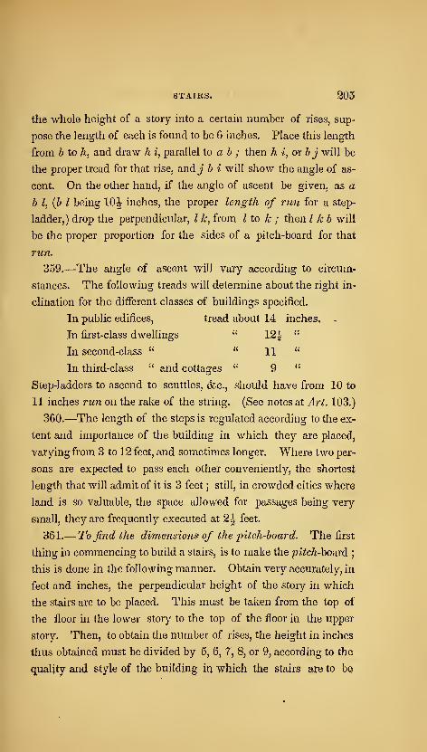
STAIRS. 205
the -whole height of a story into a certain number of rises, sup-
pose the length of each is found to be 6 inches. Place this length
from b to h, and draw h i, parallel to a b ; then h i, or b j will be
the proper tread for that rise, and j b i will show the angle of as-
cent. On the other hand, if the angle of ascent be given, as a
b I, {b I being 10|- inches, the proper length of run for a step-
ladder,) drop the perpendicular, I k, from I to k ; then I kb will
be the proper proportion for the sides of a pitch-board for that
run.
359.—The angle of ascent will vary according to circum-
stances. The following treads will determine about the right in-
clination for the different classes of buildings specified.
In public edifices, tread about 14 inches. .
In first-class dwellings " 12^ "
In second-class " "11 "
In third-class " and cottages " 9 "
Step-ladders to ascend to scuttles, &c., should have from 10 to
11 inches run on the rake of the string. (See notes at Art. 103.)
360.—The length of the steps is regulated according to the ex-
tent and importance of the building in which they are placed,
varying from 3 to 12 feet, and sometimes longer. Where two per-
sons are expected to pass each other conveniently, the shortest
length that will admit of it is 3 feet ; still, in crowded cities where
land is so valuable, the space allowed for passages being very
small, they are frequently executed at 2^ feet.
361.— To find the dimensions of the j)itch-board. The first
thing in commencing to build a stairs, is to make the ^^zVc/i-board;
this is done in the following manner. Obtain very accurately, in
feet and inches, the perpendicular height of the story in which
the stairs are to be placed. This must be taken from the top of
the floor in the lower story to the top of the floor in the upper
story. Then, to obtain the number of rises, the height in inches
thus obtained must be divided by 5, 6, 7, 8, or 9, according to the
quality and style of the building in which the stairs are to bQ
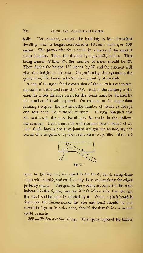
206 AMERICAN HOUSE-CARPENTER.
built. For instance, suppose the building to be a first-claSS
dwelling, and the height ascertained is 13 feet 4 inches, or 160
inches. The proper rise for a stairs in a house of this class is
about 6 inches. Then, 160 divided by 6, gives 26f inches. This
being nearer 27 than 26, the number of risers, should be 27.
Then divide the height, 160 inches, by 27, and the quotient will
give the height of one rise. On performing this operation, the
quotient will be found to be 5 inches, | and — of an inch.
Then, if the space for the extension of the stairs is not limited,
the tread can be found as at Art. 358. But, if the contrary is the
case, the whole distance given for the treads must be divided by
the number of treads required. On account of the upper floor
forming a step for the last riser, the number of treads is always
one less than the number of risers. Having obtained this
rise and tread, the pitch-board may be made in the follow-
ing manner. Upon a piece of well-seasoned board about | of an
inch thick, having one edge jointed straight and square, lay the
corner of a carpenters'-square, as shown at Fig. 255. Make a b
equal to the rise, and b c equal to the tread ; mark along those
edges with a knife, and cut it out by the marks, making the edges
perfectly square. The grain of the wood must run in the direction
indicated in the figure, because, if it shrinks a trifle, the rise and
the tread will be equally affected by it. When a pitch-board is
first made, the dimensions of the rise and tread should be pre-
served in figures, in order that, should the first shrink, a second
could be made.
362.— To lay out the string. The space required for timber
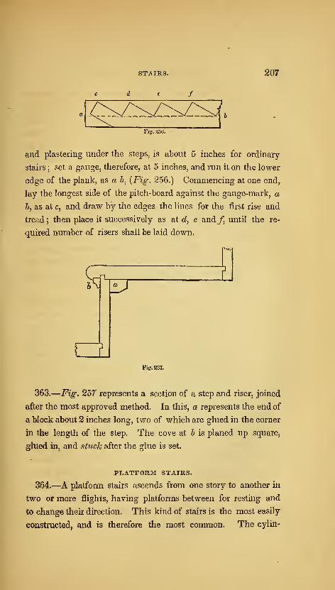
STAIRS. 207
and plastering under the steps, is about 5 inches for ordinary-
stairs ;set a gauge, therefore, at 5 inches, and run it on the lower
edge of the plank, as a b, {Fig. 256.) Commencing at one endy
lay the longest side of the pitch-board against the gauge-mark, a
b, as at c, and draw by the edges the lines for the first rise and
tread; then place it successively as at d, e and/, until the re-
quired number of risers shall be laid down.
KJ
diFig. 257.
363.
—
Fig. 257 represents a section of a step and riser, joined
after the most approved method. In this, a represents the end of
a block about 2 inches long, two of which are glued in the corner
in the length of the step. The cove at b is planed up square,
glued in, and stuck after the glue is set.
PLATFORM STAIRS.
364.—A platform stairs ascends from one story to another in
two or more flights, having platforms between for resting and
to change their direction. This kind of stairs is the most easily
constructed, and is therefore the most common. The cylin-
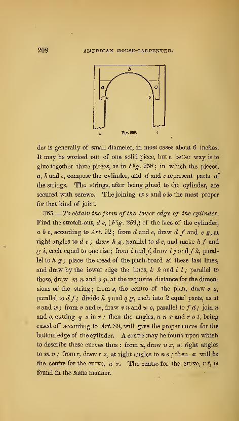
208 AMERICAN HOUSE*CARPENTEit<
Fig-. 258.
der is generally of small diameter, in most cases about 6 inches.
It may be worked out of one solid piece, but a better way is to
glue together three pieces, as in Fig. 258 ; in which the pieces,
a, h and c, compose the cylinder, and d and e represent parts of
the strings. The strings, after being glued to the cylinder, are
secured with screws. The joining at o and o is the most proper
for that kind of joint.
365.— To obtain theform of the lower edge of the cylinder.
Find the stretch-out, d e, {Fig. 259,) of the face of the cylinder,
a b c, according to Art. 92 ; from d and e, draw d f and e g, at
right angles to d e ; draw h g, parallel to d e, and make hf and
g i, each equal to one rise; from i and/, draw ij and//;, paral-
lel to h g ; place the tread of the pitch-board at these last lines,
and draw by the lower edge the lines, k h and i I ; parallel to
these, draw m n and o p, at the requisite distance for the dimen-
sions of the string ; from 5, the centre of the plan, draw s q^
parallel to df; divide h q and q g, each into 2 equal parts, as at
V and w ; from v and w, draw v n and w o, parallel tofd; join n
and 0, cutting q s inr ; then the angles, u n r and rot, being
eased off according to Art. 89, will give the proper curve for the
bottom edge of the cylinder. A centre may be found upon which
to describe these curves thus : from u, draw u x, at right angles
to mn; from r, draw r x, at right angles to no ; then x will be
the centre for the curve, u r. The centre for the curve, r t, is
found in the same manner.
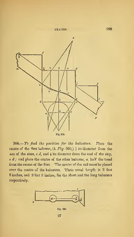
STAIRS; 20iS
Fig. 259.
366.—To find the fOsition for the balusters. Place the
centre of the first baluster, (6. Fig. 260,) \ its diameter from the
ace of the riser, c c?, and i its diameter from the end of the step,
e d ; and place the centre of the other baluster, a, half the tread
from the centre of the first. The centre of the rail must be placed
over the centre of the balusters. Their usual length is 2 feet
6 inches, and 2 feet 9 inches, for the short and the long balusters
respectively.
eFig. 260.
27
d

210 AMERICAN HOUSE-CARPENTER,
Fig. 261.
367.— To find the face-mouldfor a round hand-rail to plat-
form stairs. Case 1.— When the cylinder is small. In Fig.
261,J and e represent a vertical section of the last two steps of the
first flight, and d and i the first two steps of the second flight, of
a platform stairs, the line, e /, being the platform ; and a 6 c is
the plan of a line passing through the centre of the rail around
the cylinder. Through i and d, draw i k, and throughJ and e,
draw J k ; from k,' draw k I, parallel to / e ; from b, draw b m,,
parallel to ^ a ; from I, draw I r, parallel to k j ; from n^ draw fi
t, at right angles toj k ; on the line, o b, make o t equal to n t
;
join c and t ; on the line, j c, {Fig. 262,) make e c equal to en at
Fig. 261 ; from c, draw c t, at right angles toj c, and make c t
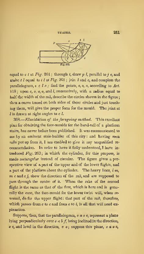
STAIRS. 211
Fig. 262.
equal to c ^ at Fig. 261 ;through t, drawp ?, parallel ioj c, and
make t I equal to ^^ Z at Fig. 261;jom I and c, and complete the
parallelogram, e c Is; find the points, o, o, o, according to Art.
118 ; upon e, o, o, o, and L successively, with a radius equal to
half the width of the rail, describe the circles shown in the figure
;
then a curve traced on both sides of these circles and just touch-
ing them, will give the proper form for the mould. The joint at
I is drawn at right angles to c I.
368.
—
Elucidation of the foregoing method. This excellent
plan for obtaining the face-moulds for the hand-rail of a platform
stairs, has never before been published. It was communicated to
me by an eminent stair-builder of this city : and having seen
rails put up from it, I am enabled to give it my unqualified re-
commendation. In order to have it fully understood, I have in-
troduced Fig. 263 ; in which the cylinder, for this purpose, is
made rectangular instead of circular. The figure gives a per-
spective view of a part of the upper and of the lower flights, and
a part of the platform about the cylinder. The heavy lines, i m,
7n c and c J, show the direction of the rail, and are supposed to
pass through the centre of it. When the rake of the second
flight is the same as that of the first, which is here and is gene-
rally the case, the face-mould for the lower twist will, when re-
versed, do for the upper flight: that part of the rail, therefore,
which passes from e to c and from c to Z, is all that will need ex-
planation.
Suppose, then, that the parallelogram, e ao c, represent a plane
lying perpendicularly over e ahf being inclined in the direction,
e c, and level in the direction, c o ; suppose this plane, e a o c,
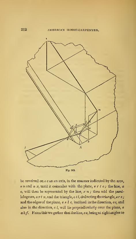
212 AMERICAN HOUSE-CARPENTER,
Fig, 263.
be revolved on e c as an axis, in the manner indicated by the ares,
n and a x, until it coincides with the plane, e r t c ;. the line, a
0, will then be represented by the line, x n ; then add the paral-^
lelogram, xrt n^ and the triangle, ctl, deducting the triangle, er s ;
and the edges of the plane, e s I c, inclined in the direction, ec, and
also in the direction, c I, will lie perpendicularly over the plane, e
«F &/, From thiswe gather that the line, c o, being at right angles tQi
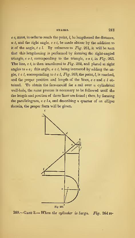
STAIRS. 213
e 0, must, in order to reach the point, I, be lengthened the distance,
n t, and the right angle, e c ^j be made obtuse by the addition to
it of the angle, t c I. By reference to Fig. 261, it will be seen
that this lengthening is performed by forming the right-angled
triangle, cot, corresponding to the triangle, c o ^, in Fig. 263.
The line, c t, is then transferred to Fig. 262, and placed at right
angles to e c ; this angle, e c t, being increased by adding the an-
gle, t c I, corresponding to t c I, Fig. 263, the point, Z, is reached,
and the proper position and length of the lines, e c and c I ob-
tained. To obtain the face-mould for a rail over a cylindrical
well-hole, the same process is necessary to be followed until the
the length and position of these lines are found; then, by forming
the parallelogram, eels, and describing a quarter of an ellipse
therein, the proper form will be given.
Fig 264.
369.—Case 2.— When the cylinder is large. Fig. 264 re-
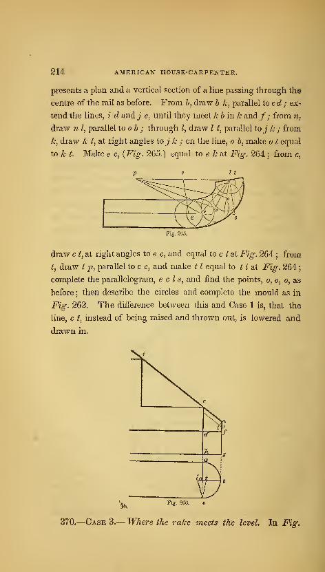
214 AMERICAN HOUSE-CARPENTER.
presents a plan and a vertical section of a line passing through the
centre of the rail as before. From 6, draw h k, parallel toed; ex-
tend the lines, i d and j e, until they meet k h in k and/ ; from n,
draw n I, parallel to oh ; through Z, draw I t^ parallel to j k ; from
k, draw k t^ at right angles to j k ; on the line, o 6, make o t equal
to k t. Make e c, [Fig. 265.) equal to e k at Fig. 264; from c,
Fig. 265.
draw c t, at right angles to e c, and equal to c f at Fig. 264 ; from
t, draw ^ 2?, parallel to c e, and make 1 1 equal to ^ Z at Fig. 264
;
complete the parallelogram, eels, and find the points, o, o, o, as
before; then describe the circles and complete the mould as in
Fig. 262. The difference between this and Case 1 is, that the
line, c t, instead of being raised and thrown out, is lowered and
drawn in.
'%, Fig. 266. c
370.
—
Case 3.— Where the rake meets the level. In Fig,
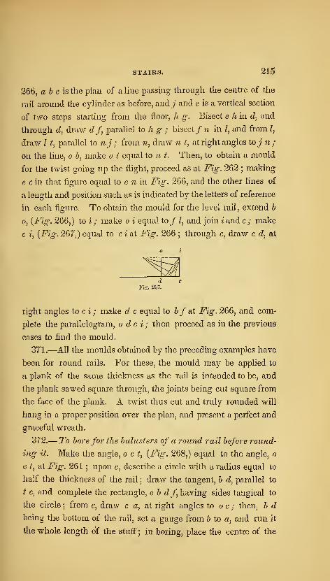
STAIRS. 215
266, ab cis the plan of a line passing through the centre of the
rail around the cylinder as before, and J and e is a vertical section
of two steps starting from the floor, h g. Bisect e h in d, and
through dj draw cZ/, parallel to h g ; bisect/ 7j in I, and from I,
draw I t, parallel to nj; from n, draw n t, at right angles toj n;
on the line, o b, make o t equal to n t. Then, to obtain a mould
for the twist going up the flight, proceed as at Fig. 262;making
e c in that figure equal to e n in Fig. 266, and the other lines of
a length and position such as is indicated by the letters of reference
in each figure. To obtain the mould for the level rail, extend b
o, {Fig. 266,) to i ; make o i equal to/ Z, and join i and c; make
c i, {Fig. 267,) equal to c i at Fig. 266;through c, draw c d, at
dFiff. 267.
right angles to c i ; make d c equal to 5/at Fig. 266, and com-
plete the parallelogram, o dc i; then proceed as int?ie previous
cases to find the mould.
371.—All the moulds obtained by the preceding examples have
been for round rails. For these, the mould may be applied to
a plank of the same thickness as the rail is intended to be, and
the plank sawed square through, the joints being cut square from
the face of the plank. A twist thus cut and truly rounded will
hang in a proper position over the plan, and present a perfect and
graceful wreath.
372.— To bore for the balusters of a round rail before round-
ing it. Make the angle, o c t, {Fig. 268,) equal to the angle, o
c t, at Fig. 261 ; upon c, describe a circle with a radius equal to
half the thickness of the rail ; draw the tangent, b d, parallel to
t c, and complete the rectangle, e b fZ/ having sides tangical to
the circle5from c, draw c a, at right angles to c ; then, b d
being the bottom of the rail, set a gauge from b to a, and run it
the whole length of the stuff; in boring, place the centre of the

216 AMERICAN HOUSE-CARPENTEii*
bit in the gauge-mark at a, and bore in the direction, a c. To do
this easily, make chucks as represented in the figure, the bottom
edge, g A, being parallel to o c, and having a place sawed out, as
e f, to receive the rail. These being nailed to the bench, the rail
will be held steadily in its proper place for boring vertically.
The distance apart that the balusters require to be, on the under
side of the rail, is one-half the length of the rake-side of the
pitch-board.
Fig. 269.
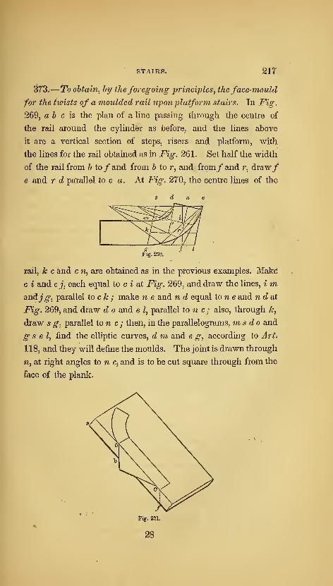
st-AiRS. Sir
^73.— To obtain^ by theforegoing principles^ the face-mould
for the twists of a moulded rail upon platform stairs. In Fig.
269, a b c is the plan of a line passing through the centre of
the rail around the cylinder as before, and the lines above
it are a vertical section of steps, risers and platform, with
the lines for the rail obtained as in Fig. 261. Set half the width
of the rail from b to/and from b to r, and from/ and r, draw/
e and r d parallel to c a. At Fig, 270, the centre lines of the
rail, k c and c w, are obtained as in the previous examples^ Mak^
c i and cj, each equal to c i at Fig. 269, and draw the lines, i m,
andj^, parallel to c k ; make n e and n d equal tone and nddii
Fig. 269j and draw d o and e ^, parallel to n c ; also, through k,
draw 5 g, parallel ton c ; then, in the parallelograms, ms do and
g s e I, find the elliptic curves, d ni and e g, according to Art^
118, and they will define the moulds. The joint is drawn through
n, at right angles to n Cj and is to be cut square through from the
face of the plank.

218 AMERICAN HOUSE-CARPENTEE.
374.
—
To apply the mould to the pla7ik. The mould obtainec?
according to the last article must be applied to both sides of the
plank, as shown at Fig. 271. Before applying the mould, the
edge, e/, must be bevilled according to the angle, c t x,dX Fig.
269 ; if the rail is to be canted up, the edge must be bevilled at
an obtuse angle with the upper face ; but if it is to be canted
down, the angle that the edge makes with the upper face must be
acute. From the spring of the curve, a, and the end, c, draw
vertical lines across the edge of the plank by applying the pitch-
board, a b c ; then, in applying the mould to the other side, place
the points, a and c, at b and/; and, after marking around it, saw
the rail out vertically. After the rail is sawed out, the bottom
and the top surfaces must be squared from the sides.
375.— To ascertain the thickness of stuff required for the
twists. The thickness of stuff required for the twists of a round
rail, as before observed, is the same as that for the straight ; but
for a moulded rail, the stuff for the twists must be thicker than
that for the straight. In Fig-. 269, draw a section of the rail be-
tween the lines, d r and ef, and as close to the line, d e, as possi-
ble ;at the lower corner of the section, draw g A, parallel to d e ;
then the distance that these lines are apart, will be the thickness
required for the twists of a moulded rail.
The foregoing method of finding moulds for rails is applicable
to all stairs which have continued rails around cylinders, and are
without winders.
WINDING STAIRS.
376.—Winding stairs have steps tapering narrower at one end
than at the other. In some stairs, there are steps of parallel width
incorporated with tapering steps ; the former are then called^yer5
and the latter winders.
377.— To describe a regular geometrical winding stairs.
In Fig. 272, abed represents the inner surface of the wall en-
closing the space allotted to the stairs, a e the length of the steps,
and ef g h the cylinder, or face of the front string. The line,
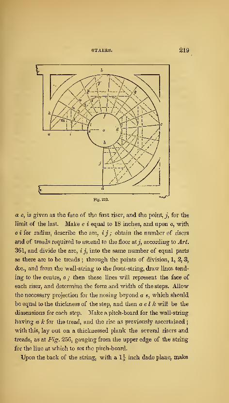
STAIRS. 219
Fig. 272.
WJ
a e, is given as the face of the first riser, and the point, j, for the
limit of the last. Make e i equal to 18 inches, and upon o, with
o i for radius, describe the arc, ij; obtain the number of risers
and of treads required to ascend to the floor at^', according to Art.
361, and divide the arc, ij, into the same number of equal parts
as there are to be treads ; through the points of division, 1, 2, 3,
&c., and from the wall-string to the front-string, draw lines tend-
ing to the centre, o ; then these lines will represent the face of
each riser, and determine, the form and width of the steps. Allow
the necessary projection for the nosing beyond a e, which should
be equal to the thickness of the step, and then a el k will be the
dimensions for each step. Make a pitch-board for the wall-string
having a k for the tread, and the rise as previously ascertained;
with this, lay out on a thicknessed plank the several risers and
treads, as at Fig. 256, gauging from the upper edge of the string
for the line at which to set the pitch-board.
Upon the back of the string, with a 1\ inch dado plane, make

^20 AMERICAN HOUSE-CARPENTER.
a succession of grooves 1^ inches apart, and parallel with th@
lines for the risers on the face. These grooves must be cut along
the whole length of the plank, and deep enough to admit of the
plank's bending around the curve, abed. Then construct a
drum, or cylinder, of any common kind of stuff, and made to fit
a curve having a radius the thickness of the string less than o a ;
upon this the string must be bent, and the grooves filled with strips
of wood, called ke^/s, which must be very nicely fitted and glued
in. After it has dried, a board thin enough to bend around on the
outside of the string, must be glued on from one end to the other,
and nailed with clout nails. In doing this, be careful not to nail
into any place where a riser or step is to enter on the face.
After the string has been on the drum a sufiicient time for the
glue to set, take it off, and cut the mortices for the steps and
risers on the face at the lines previously made ; which may be
done by boring with a centre-bit half through the string, and
nicely chisseling to the line. The drum need not be made so
large as the whole space occupied by the stairs, but merely large
enough to receive one piece of the wall-^string at once—for it
is evident that more than one will be required. The front string
may be constructed in the same manner ; taking e I instead of a
k for the tread of the pitch-board, dadoing it with a smaller dadq
plarie, and bending it on a drum of the proper size.
Fig. 273.
378.— To find tke shape and position of the timbers iieces-.
sary to support a ivinding stairs.. The dotted lines in F'ig'^
272 show the proper position of the timbers as regards the plan ;
the shape of each is obtained as follows. In Fig. 273, the linCy
1 a, is equal to a riser, less the thickness of the floor, and the
lines, 2 m, 3 ri, 4 0, 5 p and 6 q, are each equal to one ris^r, TJi^
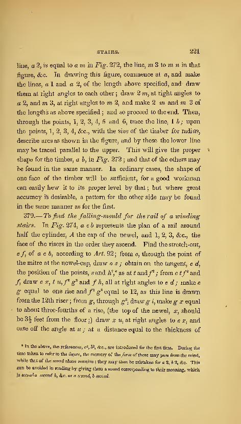
STAIRS. 221
line, a 2, is equal to a m in Fig. 272, the line, 7Ji 3 to m ?i in that
figure, &c. In drawing this figure, commence at a, and make
the lines, a 1 and a 2, of the length above specified, and draw
them at right angles to each other ; draw 2 ?ji, at right angles to
a 2, and m 3, at right angles to m 2, and make 2 m and m 3 of
the lengths as above specified ; and so proceed to the end. Then,
through the points, 1, 2, 3, 4, 5 and 6, trace the line, lb; upon
the points, 1, 2, 3, 4, &c., with the size of the timber for radius,
describe arcs as shown in the figure, and by these the lower line
may be traced parallel to the upper. This will give the proper ^
shape for the timber, a b, in Fig. 272; and that of the others may
be found in the same manner. In ordinary cases, the shape of
one face of the timber will be sufiicient, for a good workman
can easily hew it to its proper level by that ; but where great
accuracy is desirable, a pattern for the other side may be found
in the same manner as for the first.
379.— 7^0 find the falling-mould for the rail of a winding
stairs. In Fig. 274, a cb represents the plan of a rail around
half the cylinder, A the cap of the newel, and 1, 2, 3, &c., the
face of the risers in the order they ascend. Find the stretch-out,
e/, of a c b, according to Ai^t. 92; from o, through the point of
the mitre at the newel-cap, draw o s ; obtain on the tangent, e d,
the position of the points, s and h\* as at t and/^ ; from e tf^ and
/, draw e s, t u,f^ g^ and f h, all at right angles to e d ; make e
g equal to one rise and/^ ^"^ equal to 12, as this line is drawn
from the 12th riser ; from g, through g^, draw^ i, make g x equal
to about three-fourths of a rise, (the top of the newel, x, should
be 31 feet from the floor ;) draw x u, at right angles to e x, and
ease ofi" the angle at n ; at a distance equal to the thickness of
* In the above, the references, a^, b'^, &c., are introduced for the first time. During the
time taken to refer to the figure, the memory of the form of these may pass from the mind,
while that of the sound alone remains ; they may then be mistaken for a 2, 6 2, &c. This
pan be avoided in reading by giving them a sound corresponding to their meaning, whicH|s second a second b, &c. or a second, b second.
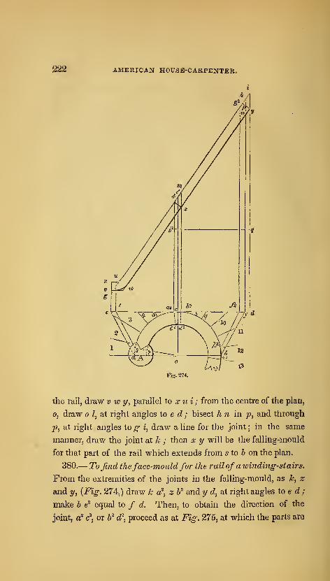
AMERICAN HOUSE-CARPENTER.
Fig. 274.
the rail, draw v w y, parallel to x u i ; from the centre of the plan,
o, draw o Z, at right angles to e d ; bisect h n in p, and through
j!?, at right angles to g i, draw a line for the joint ; in the same
manner, draw the joint at k ; then x y will be the falling-mould
for that part of the rail which extends from 5 to 6 on the plan.
380.— To find theface-mould for the rail of awindmg-stairs.
From the extremities of the joints in the falling-mould, as k, z
and y, {Fig. 274,) draw k a^, z If and y d, at right angles to e c?
;
make h e^ equal to / d. Then, to obtain the direction of the
joint, a^ c^, or W d\ proceed as at Fig. 275, at which the parts are
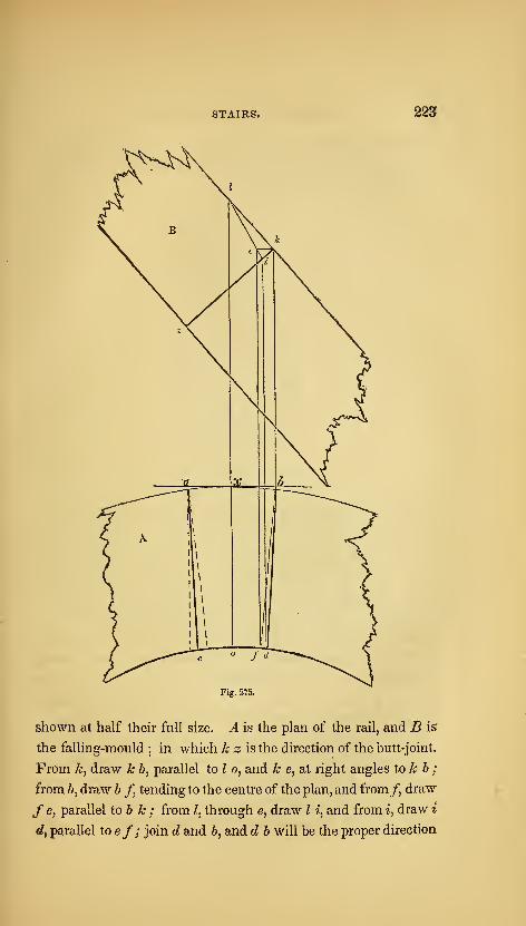
STAIRS. 223
Fig. 2T5.
shown at half their full size. A is the plan of the rail, and B is
the falling-mould; in which k z is the direction of the butt-joint.
From k, draw k b, parallel to I o, and k e, at right angles to k b ;
from b, draw b f, tending to the centre of the plan, and from/, draw
/ e, parallel Xob k ; from /, through e, draw I i, and from i, draw i
€?, parallel toef; join d and 6, and d b will be the proper direction
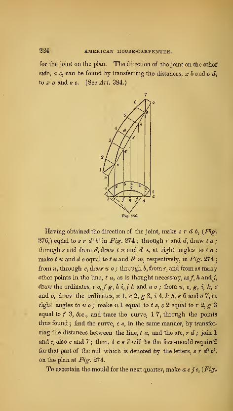
224 American house-carpenter.
for the joint oh the plan. The direction of the joint on the Otiief
side, a c, can be found by transferring the distances, x b and o dy
to X a and o c. (See Art. 384.)
7
ey/
5/ ^ i
r
3/ /
1 1/7ff
/ .
^
'LI/1
c
^\//u
<»
^ /s
3~9
C I
Fig. 276.
Having obtained the direction of the joint, make s r d b, {Fig.-
276j) equal to s r d^ b^ in Fig-. 274 ; through r and <?, draw t a ;
through s and from d, draw t u and d e, at right angles to t a ;
make t u and d e equal to ^ w and W m, respectively, in Fig. 274]
from u, through e, draw u ; through b, from r, and from as many
other points in the line, t a, as is thought necessary, as/, h andj,
draw the ordinates, r c,f g, h i,j k and ao ; from u, c, g^ i, k, e
and 0, draw the ordinates, u 1, c 2, g 3, i ^, k 5, e 6 and 7, at
right angles to u ; make w 1 equal to ^ 5, c 2 equal to r 2, ^ 3
equal to/ 3, <fec., and trace the curve, 1 7, through the points
thus found ; find the curve, c e, in the same manner, by transfer-
ring the distances between the line, t a, and the arc, r d ; join 1
and c, also e and 7 ; then, 1 c e 7 will be the face-mould required
for that part of the rail which is denoted by the letters, s r d^ b\
on the plan at Fig. 274.
To ascertain the mould for the next quarter, make acje, {Fig,
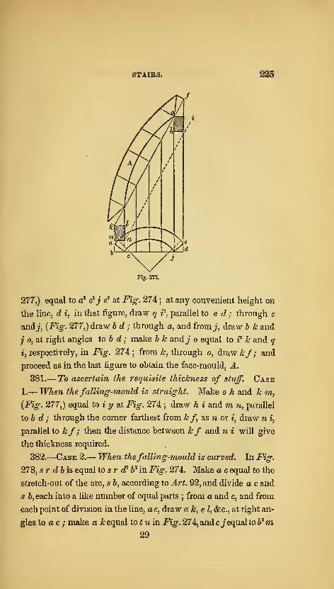
STAIRS. 225
Fig. 277.
277,) equal to a' c'j ^ at Fig. 27
A
; at any convenient height on
the line, d i, in that figure, draw q i\ parallel to e d ; through c
and 7, {Fig. 277,) draw bd ; through a, and from j, draw b k and
j 0, at right angles to b d ; make b k andj o equal to i^ k and y
1, respectively, in Fig. 27i ;from k, through o, draw kf ; and
proceed as in the last figure to obtain the face-mould, A.
381.
—
To ascertain the requisite thickness af stuff. Case
1.— When the falling-mould is straight. Make o h and k m,
{Fig. 277,) equal to i y at Fig. 274 ; draw h i and m w, parallel
tob d ; through the corner farthest from kf as n or i, draw w i,
parallel to kf; then the distance between kf and w i will give
the thickness required.
382.
—
Case 2.— When thefalling-mould is curved. In Fig.
278, sr dbis equal to s r «f 6Mn F«^. 274. Make a c equal to the
stretch-out of the arc, s b, according to Ai't. 92, and divide a c and
5 6, each into a like number of equal parts ; from a and c, and from
each point of division in the line, a c, draw a k, e I, &c., at right an-
gles to a c ; make a k equal to ^ w in Fig. 274, and cj equal to b"^m29
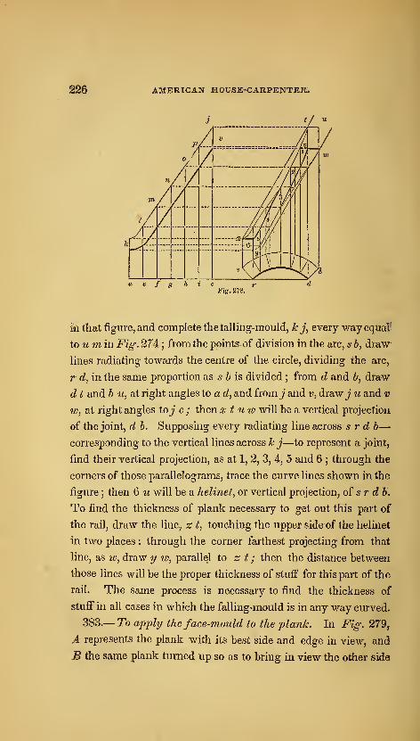
AMERICAN HOUSE-CARPENTER.
a e f g h i c
in that figure, and complete the tailing-mould, k j, every way equal''
to u m in Fig. 274: ; from the points of division in the arc, 56, draw
lines radiating towards the centre of the circle, dividing the arc,
r d, in the same proportion as s b is divided ; from d and 6, draw
d t and h w, at right angles to a d, and from j and i;, draw^" u and v
w, at right angles toj c ; then x t uw will be a vertical projection
of the joint, d b. Supposing every radiating line across s r d b—corresponding to the vertical lines across k j—to represent a joint,
find their vertical projection, as at 1, 2, 3, 4, 5 and 6 ; through the
corners of those parallelograms, trace the curve lines shown in the
figure ; then 6 u will be a helinet, or vertical projection, of sr d b.
To find the thickness of plank necessary to get out this part of
the rail, draw the line, z t, touching the upper side of the helinet
in two places : through the corner farthest projecting from that
line, as lo, draw 1/ lo, parallel to z t ; then the distance between
those lines will be the proper thickness of stuff for this part of the
rail. The same process is necessary to find the thickness of
stuff in all cases in which the falling-mould is in any way curved.
383.— To apply the face-mould to the plank. In Fig. 279,
A represents the plank with its best side and edge in view, and
B the same plank turned up so as to bring in view the other side
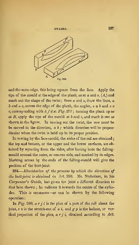
STAIRS* 227
Fig. 279.
and the same edge, this being square from the face. Apply the
tips of the mould at the edge of the plank, as at a and o, (A,) and
mark out the shape of the twist ; from a and o, draw the lines, a
b and o c, across the edge of the plank, the angles, e a b and e o
Cj corresponding with kfdaX Fig. 277 ; turning the plank up as
at B, apply the tips of the mould at b and c, and mark it out as
shown in the figure. In sawing out the twist, the saw must be
be moved in the direction, a b ; which direction will be perpen-
dicular when the twist is held up in its proper position.
In sawing by the face-mould, the sides of the rail are obtained;
the top and bottom, or the upper and the lower surfaces, are ob-
tained by squaring from the sides, after having bent the falling-
mould around the outer, or convex side, and marked by its edges.
Marking across by the ends of the falling-mould will give the
position of the butt-joint.
384.
—
Elucidation of the process hy which the direction of
the butt-joint is obtained in Art. 380. Mr. Nicholson, in his
Carpenters Guide, has given the joint a different direction to
that here shown ; he radiates it towards the centre of the cylin-
der. This is erroneous—as can be shown by the following
operation
:
In Fig. 280, arji'is the plan of a part of the rail about the
joint, s u is the stretch-out of a i, and gp is the helinet, or ver-
tical projection of the plan, arji, obtained according to Art,
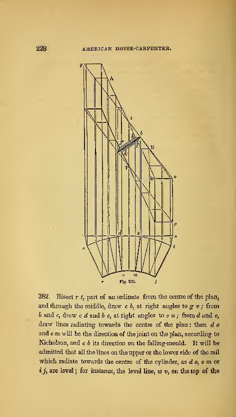
2^ AMERICAN HOUSE-CARPENTER.
Fig. 280.
382. Bisect r t, part of an ordinate from the centre of the plan,
and through the middle, draw c b, at right angles to g v ; from
b and c, draw c d and b e, at right angles to s u ; from d and e,
draw lines radiating towards the centre of the plan : then d o
and em will be the direction of the joint on the plan, according to
Nicholson, and c b its direction on the falling-mould. It will be
admitted that all the lines on the upper or the lower side of the rail
which radiate towards the centre of the cylinder, as <Z o, e w or
tJ, are level ; for instance, the level line, w v, on the top of the
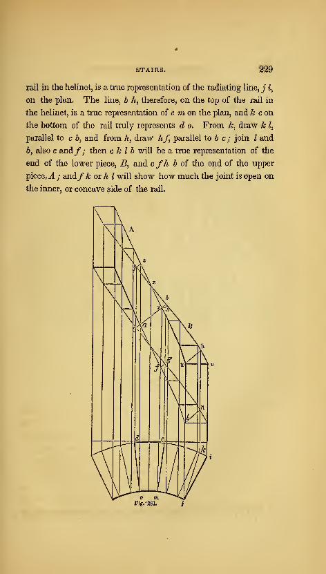
STAIRS.
rail in the helinet, is a true representation of the radiating line, j i^
on the plan. The line, b h, therefore, on the top of the rail in
the helinet, is a true representation of e w on the plan, and ^ c on
the bottom of the rail truly represents d o. From k, draw k I,
parallel to c 6, and from h, draw hf, parallel to 6 c ; join I and
b, also c and/; then c k I b will be a true representation of the
end of the lower piece, B, and cfh b of the end of the upper
piece,A ; and/ k or k I will show how much the joint is open on
the inner, or concave side of the rail.
Fig. -281. j
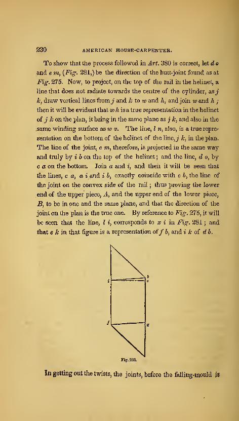
230 AMERICAN H0USE-<;ARPENTER.
To show that the process followed in Art 380 is correct, let d o
and em, {Fig. 281,) be the direction of the butt-joint found as at
Fig. 275. Now, to project, on the top of the rail in the helinet, a
line that does not radiate towards the centre of the cylinder, as^*
k, draw vertical lines from j" and k to w and A, and join w and h ;
then it will be evident that wh is a true representation in the helinet
of j k on the plan, it being in the same plane as ;' k, and also in the
.same winding surface as w v. The Hue, I n, also, is a true reprer
sentation on the bottom of the helinet of the line,j k, in the plan.
The line of the joint, e m, therefore, is projected in the same way
and truly by * 6 on the top of the helinet ; and the line, d o, by
c a on the bottom. Join a and i, arjd then it will be seen that
the lines, c a, a i and i b, exactly coincide with c b, the line of
the joint on the convex side of the rail ; thus proving the lower
end of the upper piece, A, and the upper end of the lower piece,
B, to be in one and the same plane, and that the direction of the
joint on the plan is the true one. By reference to Fig. 275, it will
be seen that the line, I i, corresponds to :?; i in Fig. 281 ; and
that e A; in that figure is a representation of/ b, and i k oi db.
Fig. 282.
Jn getting out the twists, the joints, before the falling-mould if
STAIRS. 231'
applied, are cut perpendicularly, the face-mould being long enough,
to include the overplus necessary for a butt-joint. The face-mould
for A, therefore, would have to extend to the line, i b ; and that for
B, to the line, yz. Being sawed vertically at first, a section of the
joint at the end of the face-mould for A, would be represented in
the helinet hj bifg. To obtain the position of the line, b i, on
the end of the twist, draw i s, {Fig. 282,) at right angles to if,
and make i s equal to m e at Fig. 281 ; through s, draw 5 g, pa-
rallel to if, and make s b equal to 5 6 at Fig. 281;join 6 and i /
make ifequal to i /at Fig. 281, and from /, drawfg, parallel to i
b ;theni b gf will be a perpendicular section of the rail over the
line, e m, on the plan at Fig. 281, corresponding toi b gf in the
helinet at that figure ; and when the rail is squared, the top, or'
back, must be trimmed off to the line^^ i b, and the bottom to the
line, fg.385.— To grade the front string of a stairs, having winders
in a quarter-circle at the top of theflight connected withflyers
at the bottom. In Fig. 283, a b represents the line of the facia
along the floor of the upper story, bee the face of the cylinder,
and c d the face of the front string. Make^ b equal to ^ of the
diameter of the baluster, and draw the centre-line of the rail,y^,g h i and ij, parallel to a b, b e c and c d; make g k and g I
each equal to half the width of the rail, and through k and Z,
draw lines for the convex and the concave sides of the railj parallel
to the centre-line ; tangical to the convex side of the rail, and parallel
to k m, draw no; obtain the stretch-out, g r, of the semi-circle, k
p m, according to Art. 92 ; extend ab to t, and kmtos; make c 5
equal to the length of the steps, and i m equal to 18 inches, and de-
scribe the arcs, 5 t and u 6, parallel to mp; from t, draw t w, tend-
ing to the centre of the cylinder ; from 6, and on the line, 6 us;, run
off the regular tread, as at 5, 4, 3, 2, 1 and v ; make u x equal to
half the arc, u 6, and make the point of division nearest to x, as
Vj the limit of the parallel steps, or flyers; make r equal to mz ;
from 0, draw aV at right angles to n 0, and equal to one rise j
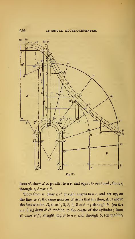
232 AMERICAN HOUSE-CARPENTER.
Fig. 283.
from a", draw c^ s, parallel to n o, and equal to one tread ; from s,
through 0, draw s b^.
Then from w, draw w c', at right angles to n o, and set up, on
the line, w c', the same number of risers that the floor, A, is above
the first winder, B, as at 1, 2, 3, 4, 5 and 6 ; through 5, (on the
arc, 6 u,) draw cP e\ tending to the centre of the cylinder ; from
e', draw e^f^, at right angles to n o, and through 5, (on the line,
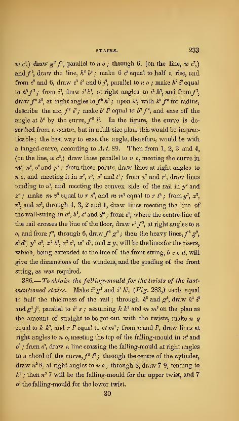
STAIRS. 233
V) <?,) draw g^f^, parallel tono ; through 6, (on the line, w c\)
and/^, draw the Ime, K^ If ; make 6 c" equal to half a rise, and
from c^ and 6, draw c^ i^ and 6/, parallel to 7i o ; make h' i' equal
to A'^/%- from i", draw iH-^, at right angles to i^ h^, and from/^,
draw/^ F, at right angles to/^ h^ ; upon /r^, with k"^ f^ for radius,
describe the arc,/^ i%- make 6^ P equal to Zj^/'^j and ease off the
angle at b^ by the curvOj/^ f. In the figure, the curve is de-
scribed from a centre, but in a full-size plan, this would be imprac-
ticable ; the best way to ease the angle, therefore, would be with
a tanged- curve, according to Art. 89. Then from 1, 2, 3 and 4,
(on the line, w c^,) draw lines parallel to n o, meeting the curve in
m?, 7^, 0^ and p^ ; from these points, draw lines at right angles to
n 0, and meeting it in x^. r^, s^ and f ; from x^ and r'^, draw lines
tending to u^, and meeting the convex side of the rail in y"^ and
z^ ; make ni v^ equal to r s"^, and m w"^ equal to r f ; from y'^, z^j
v^, and w^, through 4, 3, 2 and 1, draw lines meeting the line of
the wall-string in a^, 6^, & and d^ ; from e^, where the centre-line of
the rail crosses the line of the floor^ draw e'/^, at right angles to n
0, and from/\ through 6, draw/* g^ ; then the heavy lines,f^ g^j
^ <f, if' a^, z' If, v^ &, vf d^, and z y, will be the lines for the risers,
which, being extended to the line of the front string, b e c d, will
give the dimensions of the winders, and the grading of the front
string, as was required.
386.— To obtain the falling-mouldfor the twists of the last-
Tnentioned stairs. Make i^ g^ and i^ h^, {Fig. 283,) each equal
to half the thickness of the rail ; through h^ and g^, draw h^ i^
and g^f, parallel to r s ; assuming k k^ and m iif on the plan as
the amount of straight to be got out with the twists, make n q
equal to k k^, and r f equal to m iri? ; from n and P, draw lines at
right angles to n o, meeting the top of the falling-mould in n^ and
0* ; from o^, draw a line crossing the falling-mould at right angles
to a chord of the curve, /^ P ; through the centre of the cylinder,
draw u^ 8, at right angles to n o ; through 8, draw 7 9, tending to
k^ ; then 7i^ 7 will be the falling-mould for the upper twist, and 7
o' the falling-mould for the lower twist.
30
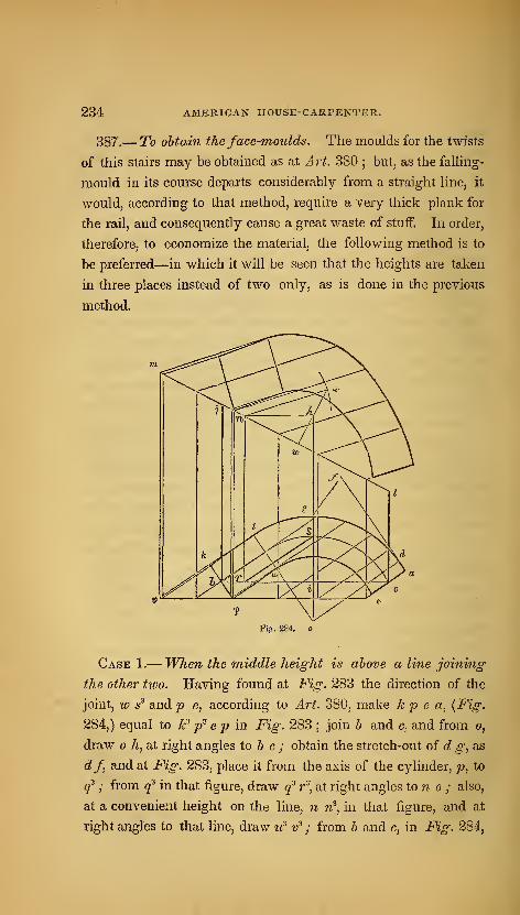
234 AMERICAN HOUSE-CARPENTER.
387.— To obtain the face-moulds. The moulds for the twists
of this stairs may be obtained as at Art. 380 ; but, as the falhng-
mould in its course departs considerably from a straight line, it
would, according to that method, require a very thick plank for
the rail, and consequently cause a great waste of stuff. In order,
therefore, to economize the material, the following method is to
be preferred—in which it will be seen that the heights are taken
in three places instead of two only, as is done in the previous
method.
Fiff. 284.
Case 1.— When the middle height is above a line joining
the other two. Having found at Fig. 283 the direction of the
joint, w s^ and p e, according to Art. 380, make k p e a, (Fig.
284,) equal to k^ p^ e p in Fig. 283;join b and c, and from o,
draw h, at right angles to 6 c ; obtain the stretch-out of c? ^, as
df, and at Fig. 283, place it from the axis of the cylinder, p, to
q^ ; from q^ in that figure, draw q^ r"', at right angles ton o ; also,
at a convenient height on the line, n 7i^, in that figure, and at
right angles to that line, draw u^ v^ ; from b and c, in Fig. 284,
STAIRS. 235;
draw b j and c I, at right angles to 6 c ; make b j equal to w' n^ in
Fig-. 283, i /i equal to lo^ r^ in that figure, and c Z equal to v* 9;
from Z, through j, draw I tn ; from h, draw /i w, parallel to c b ;
from w, draw n r, at right angles to b c, and join r and s ; through
the lowest corner of the plan, as p, draw v e, parallel to 6 c ; from
a, e, u, p, k, t, and from as many other points as is thought ne-
cessary, draw ordinates to the base-line, v e, parallel to r 5/
through h, draw lo x, at right angles to m I ; upon fi, with r s for
radius, describe an intersecting arc at x, and join n and x ; from
the points at which the ordinates from the plan meet the base-
line, V e, draw ordinates to meet the line, m I, at right angles to v
e ; and from the points of intersection on m I, draw correspond-
ing ordinates, parallel to n x ; make the ordinates which are pa-
rallel to n X of a length corresponding to those which are parallel
to r s, and through the points thus found, trace the face-mould
as required.
Case 2.— When the middle height is below a line joinijig
the other tivo. The lower twist in Fig. 283 is of this nature.
The face-mould for this is found at Fig. 285 in a manner similar
to that at Fig. 284. The heights are all taken from the top of
the falling-mould at Fig. 283 ; h j being equal to ?^ 6 in Fig. 283,
i h equal to x^ y^ in that figure, and cltQf ol Draw a line
through J and Z, and from /i, draw h n, parallel to 6 c ; from w,
draw n r, at right angles to b c, and join r and s ; then r s will be
the bevil for the lower ordinates. From h, draw h x, at right an-
gles to j I ; upon n, with r s for radius, describe an intersecting
arc at x, and join n and x ; then n x will be the bevil for the upper
ordinates, upon which the face-mould is found as in Case 1.
388.
—
Elucidation of the foregoing method.—This method
of finding the face-moulds for the handrailing of winding stairs,
being founded on principles which govern cylindric sections, may
be illustrated by the following figures. Fig. 286 and 287 repre-
sent solid blocks, or prisms, standing upright on a level base, b d ',
the upper surface,j a forming oblique angles with the face, b I—
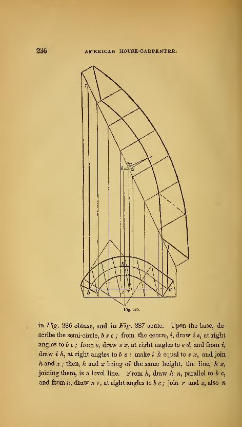
236 AMERICAN HOUSE-CARPENTER.
Fig. 285.
in Fig. 286 obtuse, and in Fig. 287 acute. Upon the base, de-
scribe the semi-circle, 65c; from the centre, «, draw i 5, at right
angles to & c ; from 5, draw 5 x, at right angles to e d, and from ^,
draw i h, at right angles to 6 c ; make i h equal to s x, and join
h and x ; then, h and x being of the same height, the line, h x,
joining them, is a level line. From h, draw h n, parallel to b c,
and from w, draw n r, at right angles to 6 c ; join r and s, also n
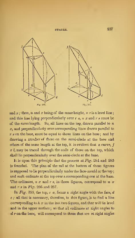
STAIRS. 237
Fiff. 286.
andx ; then, ?i and x being of the same height, ;/ .ris a level line
;
and this line lying perpendicularly over r s, n x and r s must be
of the same length. So, all lines on the top, drawn parallel to n
.T, and perpendicularly over corresponding lines drawn parallel to
r 5 on the base, must be equal to those lines on the base ; and by
drawing a number of these on the semi-circle at the base and
others of the same length at the top, it is evident that a curve, j
X Z, may be traced through the ends of those on the top, which
shall lie perpendicularly over the semi-circle at the base.
It is upon this principle that the process at Fig. 284 and 285
is founded. The plan of the rail at the bottom of those figures
is supposed to lie perpendicularly under the face-mould at the top
;
and each ordinate at the top over a corresponding one at the base.
The ordinates, n x and r s, in those figures, correspond to n x
and 7- s in Fig. 286 and 287.
In Fig. 288, the top, e a, forms a right angle with the face, d
c ; all that is necessary, therefore, in this figure, is to find a line
corresponding to h x in the last two figures, and that will lie level
and in the upper surface ; so that all ordinates at right angles to
d r on the base, will correspond to those that are at right angles

238 AMERICAN HOUSE-CARPENTER.
Fig. 288. r
to e c on the top. This ehicidates Fig. 276; at which the lines,
h 9 and i 8, correspond to h 9 and i 8 in this figure.
Fig. 289.
389.— To find the bevil for the edge of the flank. The
plankj before the face-mould is applied, must be bevilled accord-
ing to the angle which the top of the imaginary block, or prism,
in the previous figures, makes with the face. This angle is de-
termined in the following manner : draw w i, {Fig. 289,) at right
angles to i s, and equal to to h at Fig. 284 ; make i s equal to i s in
that figure, and join w and s ; then sw p will be the bevil required
in order to apply the face-mould at Fig. 284. In Fig. 285, the
middle height being below the line joining the other two, the bevil
is therefore acute. To determine this, draw i s, {Fig. 290,) at
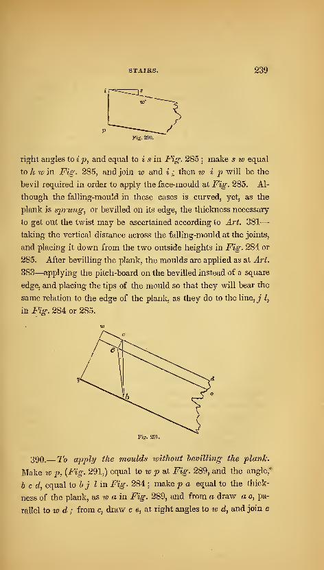
STAIRS. 239
right angles to i p, and equal to i 5 in Fig. 285 ; make s id equal
to A w? in Fig. 285, and join w and i ^ then lo i p will be the
bevil required in order to apply the face-mould at Fig. 285. Al-
though the falling-mould in these cases is curved, yet, as the
plank is sprung, or bevilled on its edge, the thickness necessary
to get out the twist may be ascertained according to Art. 381
—
taking the vertical distance across the falling-mould at the joints,
and placing it down from the two outside heights in Fig. 284 or
285. After bevilling the plank, the moulds are applied as at Art.
383—applying the pitch-board on the bevilled instead of a square
edge, and placing the tips of the mould so that they will bear the
same relation to the edge of the plank, as they do to the line, j I,
in Fig. 284 or 285.
Fig. 291.
390.— To apply the moulds without bevilling the plank.
Make w p, {Fig. 291,) equal to w p bX Fig. 289, and the angle,*
h c d, equal to 6 j I in Fig. 284 ; make p a equal to the thick-
ness of the plank, as lo a in Fig. 289, and from a draw a o, pa-
rallel iowd; from c, draw c e, at right angles to w c?, and join e
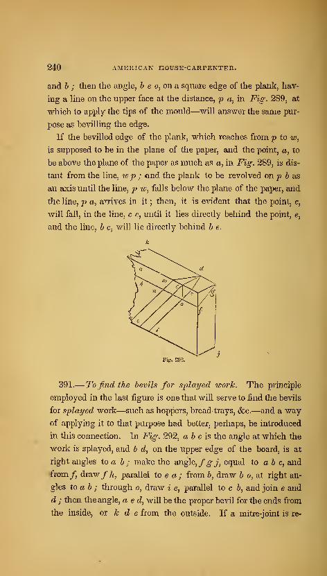
240 AMERICAN HOUSE-CARPENTER.
and h ; then the angle, 6 e o, on a square edge of the plank, hav-
ing a line on the upper face at the distance, p a, in Fig. 289, at
which to apply the tips of the mould—will answer the same pur-
pose as bevilling the edge.
If the bevilled edge of the plank, which reaches from p to w,
is supposed to be in the plane of the paper, and the point, a, to
be above the plane of the paper as much as a, in Fig. 289, is dis-
tant from the line, lo p ; end the plank to be revolved on p b as
an axis until the line, p tv, falls below the plane of the paper, and
the line, p a, arrives in it ; then, it is evident that the point, c,
will fall, in the line, c c, until it lies directly behind the point, e,
and the line, b c, will lie directly behind b e.
Fig-. 292.
391.— To find the bevils for splayed icork. The principle
employed in the last figure is one that will serve to find the bevils
for splayed work—such as hoppers, bread-trays, &c.—and a way
of applying it to that purpose had better, perhaps, be introduced
in this connection. In Fig. 292, ab cis the angle at which the
work is splayed, and b d, on the upper edge of the board, is at
right angles to a b ; make the angle, fgj, equal to a b c, and
€rom/, draw/A, parallel to e a; from b, draw b o, at right an-
gles to ab ; through o, draw i e, parallel to c b, and join e and
d ; then the angle, a e d, will be the proper bevil for the ends from
the inside, or k d e from the outside. If a mitre-joint is re-
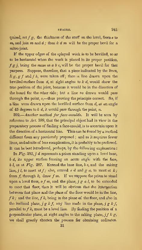
BTAIRS* 24i.
quifed, setfg, the thickness of the stuff on the level, from e to
m, and join m and d ; then k d m, will be the proper bevil for a
mitre-joint.
If the upper edges of the splayed work is to be bevilled, so as
to be horizontal when the work is placed in its proper position^
fSh being the same as a 6 c, will be the proper bevil for that
purpose. Suppose, therefore, that a piece indicated by the lineSj
k g^ gf and/A, were taken off; then a line drawn upon the
bevilled surface from d, at right angles to k d^ would show the
true position of the joint, because it would be in the direction of
the board for the other side ; but a line so drawn would pass
through the point, o,-—thus proving the principle correct. So, if
a line were drawn upon the bevilled surface from d, at an angle
of 45 degrees to k d, it would pass through the point, n.
392.
—
Another method for face-moulds. It will be seen by
reference to Art. 388, that the principal object had in view in the
preparatory process of finding a face-mould, is to ascertain upon it
the direction of a horizontal line. This can be found by a method
different from any previously proposed; and as it requires fewer
lines, and admits of less complication, it is probably to be preferred.
It can be best introduced, peihaps, by the following explanation
:
In Fig. 293, J d represents a prism standing up<3n a level base,
h d, its tipper surface forming an acute angle with the faccj
b I, as at Fig. 287. Extend the base line, b c, and the raking
line, _; I, to meet at/; also, extend e d and ^ a, to meet at k;
from /, through k, draw / m. If we suppose the prism to stand
tipon a level floor, ofm, and the plane,j^ a I, to be extended
to meet that floor, then it will be obvious that the intersection
between that plane and the plane of the floor would be in the line,
f k; and the \ine,fk, being in the plane of the floor, and also in
the inclined plane, J ^ kf, any line made in the plane,j^ kf,
parallel tofk, must be a leVel line. By finding the position of a
perpendicular plane, at right angles to the raking plane,j/^ g,
We shall greatly shorten the process for obtaining ordinates.
31
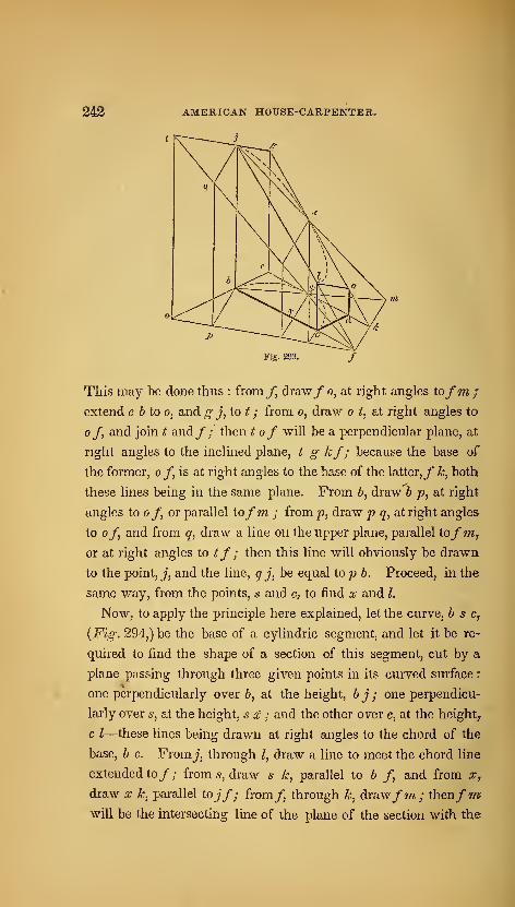
242 AMERICAN HOUSE-CARPENTER.
Fig. 293,
This may be done thus : from/, draw/ o, at right angles to/m/
extend e 6 to o, and g j, to t ; from o, draw o t, at right angles to
of, and join t and/; then t of will be a perpendicular plane, at
right angles to the inclined plane, t g kf; because the base of
the former, o /, is at right angles to the base of the latter,/ k, both
these lines being in the same plane. From 6, draw h p, at right
angles to of or parallel tofm ; from jt?, draw p q, at right angles
to of and from q, draw a line on the upper plane, parallel tofm,or at right angles to tf; then this line will obviously be drawn
to the point, J, and the line, q j, be equal top h. Proceed, in the
same way, from the points, 6' and c, to find x and I.
Now, to apply the principle here explained, let the curve, h s c,
{Fig. 294,) be the base of a cylindric segment, and let it be re-
quired to find the shape of a section of this segment, cut by a
plane passing through three given points in its curved surface
:
one perpendicularly over &, at the height, h j ; one perpendicu-
larly over 5, at the height, s x ; and the other over c, at the height^
c I—these lines being drawn at right angles to the chord of the
base, b c. Fromj, through I, draw a line to meet the chord line
extended to/; from 5, draw s k, parallel to b f and from x,
draw X k, parallel tojf; from/ through k, draw/m; thenfmwill be the intersecting line of the plane of the section with th©
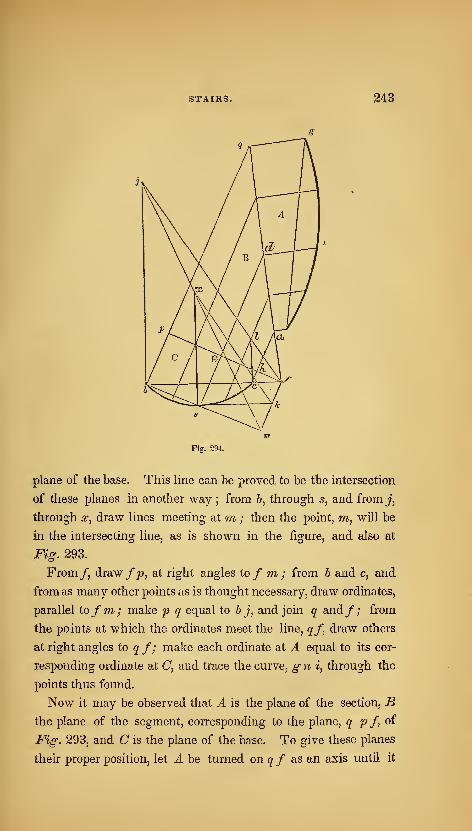
STAIRS. 243
Fig. 294.
plane of the base. This line can be proved to be the intersection
of these planes in another way ; from 6, through s, and from j,
through X, draw lines meeting at m ; then the point, m, will be
in the intersecting line, as is shown in the figure, and also at
Fig. 293.
From/, draw/p, at right angles to/ m; from b and c, and
from as many other jDoints as is thought necessary, draw ordinates,
parallel tofm; make p q equal to b j, and join q and/; from
the points at which the ordinates meet the line, qf, draw others
at right angles to q f; make each ordinate at A equal to its cor-
responding ordinate at C, and trace the curve, gni, through the
points thus found.
Now it may be observed that A is the plane of the section, Bthe plane of the segment, corresponding to the plane, q p f, oi
Fig. 293, and C is the plane of the base. To give these planes
their proper position, let A be turned on qf as an axis until it

844 AMERICAN HOUSE-CARPENTER.
Stands perpendicularly over the line, qf, and at right angles to
the plane, B ; then, while A and B are fixed at right angles^ let
B be turned on the line, j) /, as an axis until it stands perpendicu-
larly over p /, and at right angles to the plane, C ; then the plane,
A, will lie over the plane, C, with the several lines on one corres-
ponding to those on the other;the point, «, resting at Z, tjie point,
n, at x^ and g at j ; and the curve, g n i, lying perpendicularly
over b s c—as was required. If we suppose the cylinder to he
cut by a level plane passing through the point, Z, (as is done in
finding a face-mould,) it will be obvious that lines corresponding
to 9'/ and p/ would meet in I ; and the plane of the section, A^
the plane of the segment, B, and the plane of the base, C, would
all meet in that point.
393.— To find the face-mouldfor a hand-rail according to
the principles explained in the previous ai'ticle. In Fig. 295,
a e cf is the plan of a hand-rail over a quarter of a cylinder ; and
in Fig, 296, a b c d is the falling-mould; / e being equal to the
stretch-out of a df in Fig. 295. From c, draw c h, parallel to
ef; bisect h c in i, and find a point, as b, in the arc, df, {Fig.
295,) corresponding to i in the line, he; from i, {Fig. 296,) to
the top of the falling-mould, draw i j, at right angles to he; at Fig.
295, from c, through b, draw c g, and from b and c, draw b j and
c k, at right angles to ^ c ; make c k equal to h g at Fig. 296,
and bj equal to ij at that figure; from k, through j, draw k g,
and from g, through a, drawgp ; then gp will be the intersecting
line, corresponding tofm in Fig. 293 and 294 ; through e, draw
p 6, at right angles to gp, and from c, draw c q, parallel to g-p ;
make r q equal to h g at Fig. 296;joinp and q, and proceed as
in the previous examples to find the face-mould, A. The joint
of the face-mould, u v, will be more accurately determined by
finding the projection of the centre of the plan, o, as at w
;
joining s and w, and drawing u v, parallel to s w.
It may be noticed that c k and b j are not of a length corres-
ponding to the above directions : they are butj the length given.

STAIRS. 245
Fig. 295.
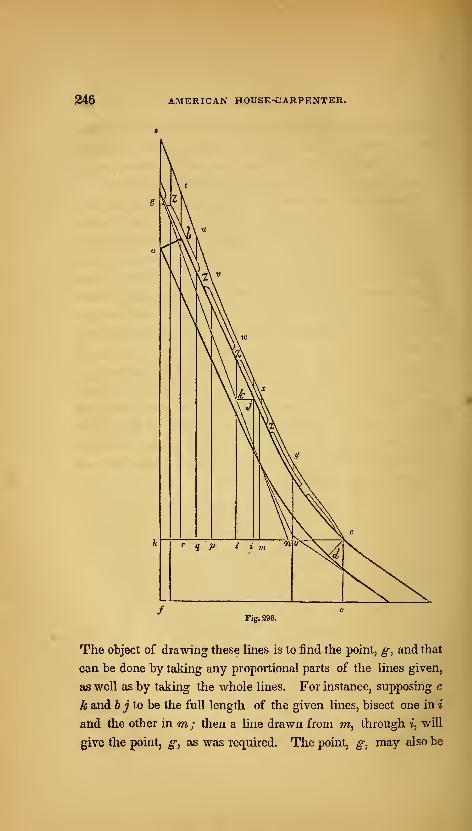
AMERICAN HOUSE-OARPENTER.
Fig. 296.
The object of drawing these lines is to find the point, g, and that
can be done by taking any proportional parts of the lines given,
as well as by taking the whole lines. For instance, supposing c
k and b j to be the full length of the given lines, bisect one in i
and the other in m; then a line drawn from m, through i, will
give the point, g, as was required. The point, g, may also be
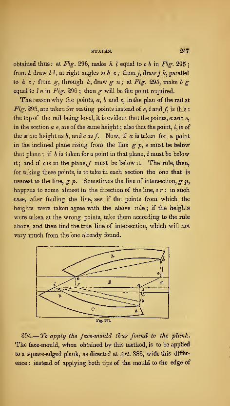
STAIRS. 247
obtained thus : at Fig. 296, make h I equal to c 6 in Fig. 295;
from /, draw I k, at right angles to A c ; from j, draw^* k, parallel
to h c ; from g, through k, draw g n; at i^«^. 295, make b gequal to / ri in Fig. 296 ; then ^ will be the point required.
The reasonwhy the points, a, b and c, in the plan of the rail at
Fig. 295, are taken for resting points instead of e, i and/, is this :
the top of the rail being level, it is evident that the points, a and e,
in the section a e, are of the same height ; also that the point, i, is of
the same height as b, and c as /. Now, if a is taken for a point
in the inclined plane rising from the line g p, e must be below
that plane ; if b is taken for a point in that plane, i must be below
it ; and if c is in the plane,/ must be below it. The rule, then,
for taking these points, is to take in each section the one that is
nearest to the line, g p. Sometimes the line of intersection, g p,
happens to come almost in the direction of the line, er : in such
case, after finding the line, see if the points from which the
heights were taken agree with the above rule ; if the heights
were taken at the wrong points, take them according to the rule
above, and then find the true line of intersection, which will not
vary much from the one already found.
Fig. 297.
394.—To apply the face-mould thus found to the plank.
The face-mould, when obtained by this method, is to be applied
to a square-edged plank, as directed at Art. 383, with this differ-
ence : instead of applying both tips of the mould to the edge of
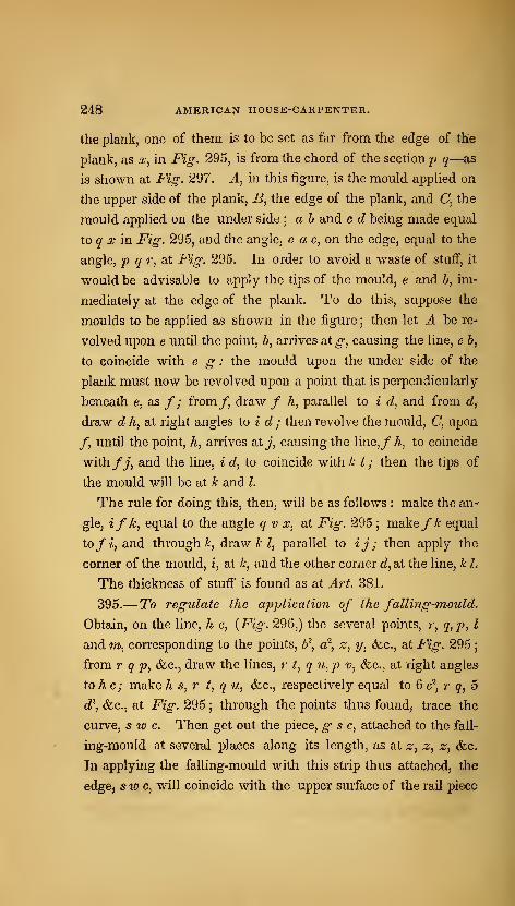
248 AMERICAN HOUSE-CARPENTER.
the plank, one of them is to be set as far from the edge of the
plankj as x^ in Fig. 295, is from the chord of the section p q—as
is shown at Fig. 297. A^ in this figure, is the mould applied on
the upper side of the plank, 5, the edge of the plank, and C, the
mould applied on the under side ; a h and c d being made equal
to g' a: in Fig. 295, and the angle, e a c, on the edge, equal to the
angle, p q r, at Fig. 295. In order to avoid a waste of stuff, it
would be advisable to apply the tips of the mould, e and 6, im-
mediately at the edge of the plank. To do this, suppose the
moulds to be applied as shown in the figure ; then let A be re-
volved upon e until the point, 6, arrives at ^, causing the line, e 6,
to coincide with e g : the mould upon the under side of the
plank must now be revolved upon a point that is perpendicularly
beneath e, as /; from/, draw / A, parallel to i d, and from </,
draw d h, at right angles to i d ; then revolve the mould, C, upon
/, until the point, h, arrives at j, causing the line,/ A, to coincide
with/j, and the line, i d, to coincide with k /; then the tips of
the mould will be at k and I.
The rule for doing this, then, will be as follows : make the an-
gle, ifk, equal to the angle q v x, at Fig. 295 ; makefk equal
to fi, and through i', draw A; Z, parallel to ij; then apply the
corner of the mould, i, at i', and the other corner dl, at the line, k I,
The thickness of stuff is found as at Art. 381.
395.— To regulate the application of the falling-moulds
Obtain, on the line, k c, {Fig. 296,) the several points, r, q,p, I
and m, corresponding to the points, b^, a^, z, y, &c., at Fig. 295
;
from r q p, &.C., draw the lines, r t, q u,p v, &c., at right angle&
to he; make h s, r t, q u, &c., respectively equal to 6 c^, r q, 5
d\ &c., at Fig. 295 ; through the points thus found, trace the
curve, s w c. Then get out the piece, g s c, attached to the fall-
ing-mould at several places along its length, as at z, z, z, (fcc.
In applying the falling-mould with this strip thus attached, the
edge, sw c, will coincide with the upper surface of the rail piece
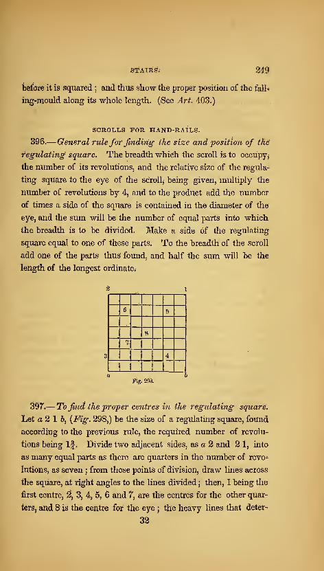
feTAIRg. 249
before it is squared ; and thus show the proper position of the fall-;
ing-mould along its whole length. (See Art. 403.)
SCROLLS FOR HAND-RAILS.
396.
—
General rule for finding- the size and position of the
regulating square. The breadth which the scroll is to occupy^
the number of its revolutions, and the relative size of the regula-
ting square to the eye of the scroll, being given, multiply the
number of revolutions by 4, and to the product add the number
of times a side of the square is contained in the diameter of the
eye, and the sum will be the number of equal parts into which
the breadth is to be divided. Make a side of the regulating
square equal to one of these parts. To the breadth of the scroll
add one of the parts thus found, and half the sum will be the
length of the longest ordinate.
6 _5
ft_
4
Fig. 298.
397.—To find the proper centres in the regulating square.
Let a2 1 b, {Fig. 298,) be the size of a regulating square, found
according to the previous rule, the required number of revolu-
tions being If. Divide two adjacent sides, as a 2 and 2 1, into
as many equal parts as there are quarters in the number of revo-
lutions, as seven ; from those points Of division, draw lines across
the square, at right angles to the lines divided ; then, 1 being the
first centre, ^, 3, 4, 5, 6 and 7*, are the centres for the other quar-
ters, and 8 is the centre for the eye ; the heavy lines that deter*
32

290 AMERICAN HOUSE-CARPENTER.
mine these centres being each one part less in length than its pte*
ceding line.
Fig. 299.
398.
—
To describe the scrollfor a hand-rail over a curtail
step. Let a b, (Fig. 299,) be the given breadth, If the given
number of revolutions, and let the relative size of the regulating
square to the eye be |- of the diameter of the eye. Then, by the
rule. If multiplied by 4 gives 7, and 3, the number of times a
side of the square is contained in the eye, being added, the sum
is 10. Divide a b, therefore, into 10 equal parts, and set one from
6 to c ; bisect a c in e ; then a e will be the length of the longest
ordinate, (1 c? or 1 e.) From a, draw a d, from e, draw e 1, and
from b, draw bf, all at right angles to a & ; make e 1 equal to e
o, and through 1, draw 1 d, parallel to a b ; set b c from 1 to 2,
and upon 1 2, complete the regulating square ; divide this square
as at Fig. 298 ; then describe the arcs that compose the scroll, as
follows : upon 1, describe d e; upon 2, describe e f; upon 3,
describe/§• ; upon 4, describe g h, &c. ; make d I equal to the
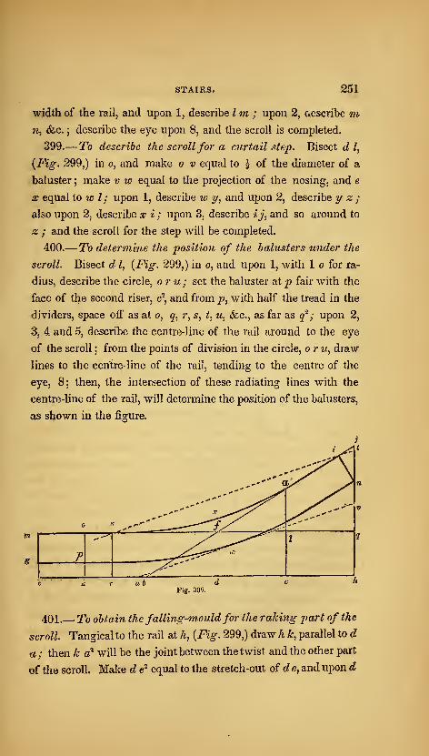
STAIRS. 261
width of the rail, and upon 1, describe Im ; upon 2, aescribe mw, &c. ; describe the eye upon 8, and the scroll is completed.
399.—To describe the scrollfor a curtail step. Bisect d I,
{Fig. 299,) in o, and make o v equal to ^ of the diameter of a
baluster ; make v w equal to the projection of the nosing, and e
X equal to w I; upon 1, describe w y, and upon 2, describe ^ z ;
also upon 2, describe a; i ; upon 3, describe ij, and so around to
z ; and the scroll for the step will be completed.
400.—To determine the position of the balusters under the
scroll. Bisect d I, {Fig. 299,) in o, and upon 1, with 1 o for ra-
dius, describe the circle, or u; set the baluster at p fair with the
face of the second riser, c\ and from p, with half the tread in the
dividers, space off as at o, q^ r, 5, t, w, &c., as far as cf ; upon 2,
3, 4 and 5, describe the centre-line of the rail around to the eye
of the scroll ; from the points of division in the circle, o r m, draw
lines to the centre-line of the rail, tending to the centre of the
eye, 8 ; then, the intersection of these radiating lines with the
centre-line of the rail, will determine the position of the balusters,
as shown in the figure.
Fig. 300.
401.—To obtain the falling-mouldfor the raking part of the
scroll. Tangical to the rail at h, {Fig. 299,) draw h k, parallel to d
a; then k a^ will be the joint between the twist and the other part
of the scroll. Make d ^ equal to the stretch-out of de^ and upon d
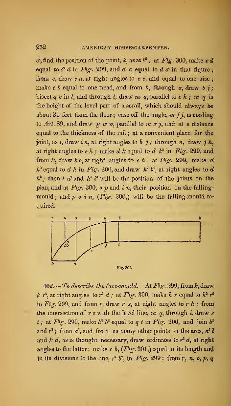
AMERICAN HOUSErCARPENTER.
e^, find the position of the point, ^, as at Ic^ ; at Fig: 300, make e d
equal to e^ d in Fig. 299, and d c equal to d & in that figure
;
from c, draw c a, at right angles to e c, and equal to one rise;
make c h equal to one tread, and from 6, through a, draw 6 ^"
;
bisect £f e in Zj and through Z, draw w g', parallel to e h ; m q is
the height of the level part of a scroll, which should always be
about 3| feet from the floor • ease off the angle, nifj, according
to Art. 89, and draw g w n, parallel to m x j, and at a distance
equal to the thickness of the rail ; at a convenient place for the
joint, as i, draw i n, at right angles to b j ; through n, draw ; /»,
at right angles to e h ; make d k equal to d k^ in Fig. 299, and
from k, draw k o, at right angles to e h ; at Fig. 299, make d
¥ equal to d h in Fig. 300, and draw A^ 6^, at right angles to d
h? ; then k c^ and W t^ will be the position of the joints on the
plan, and at Fig. 300, o p and i n, their position on the falling-
mould ; and p o i n, {Fig. 300,) will be the falling-mould re-
quired.
.
// e
f ^
i aFig. 301.
402.— To describe theface-mould. At Fig. 299, from^, draw
k r*^, at right angles to r^ d ; at Fig. 300, make h r equal to h^ r^
in Fig. 299, and from r, draw r s, at right angles to r A ; from
the intersection of r s with the level line, m q, through i, draw s
t ; at Fig. 299, make h'' b"^ equal to q t m. Fig. 300, and join Wand r^ ; from c^^ and from as many other points in the arcs, a' I
and k d, as is thought necessary, draw ordinates to r^ d, at right
fingles to the latter ; make r &, {Fig. 301,) equal in its length and
in its divisions to the line, r"^ b\ in Fig. 299;from r, n, p, |?, ^
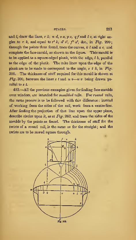
STAIRS. 253
and I, draw the lines, r k, n d, o a, p e, qf and I c, at right an-
gles to r b, and equal to r' kj d? /, /^ a^, &c., in Fig. 299
;
through the points thus found, trace the curves, k I and a c, and
complete the face-mould, as shown in the figure. This mould is
to be applied to a square-edged plank, with the edge, I 6, parallel
to the edge of the plank. The rake lines upon the edge of the
plank are to be made to correspond to the angle, s t h, in Fig.
300. The thickness of stuff required for this mould is shown at
Fig. 300, between the lines s t and u v—u v being drawn pa^
rallel to s t.
403.—All the previous examples given for finding face-moulds
over winders, are intended for moulded rails. For round rails,
the same process is to be followed with this difference : instead
of working from the sides of the rail, work from a centre-line.
After finding the projection of that line upon the upper plane,
describe circles upon it, as at Fig. 262, and trace the sides of the
moulds by the points so. found. The thickness of stuff for the
twists of a round rail, is the same as for the straight ; and the
twists are to be sawed square through.
ffs. 30S.
^04 AMERICAN HOtrSErCARPENTEK.
404.
—
To ascertain theform of the newel-capfrom a seetion
of the rail. Draw a b, {Fig. 302,) through the widest part of
the given section, and parallel to c c? ; bisect a bin e, and through
a, ^ and b. draw hi,fg and kj, at right angles to a 6 ; at a con-
venient place on the line,/^, as o, with a radius equal to half
the width of the cap, describe the circle, i j g ; make r I equal
to e b ox e a ; join I and J, also I and i; from the curve,/ 6, to
the line, I j, draw as many ordinates as is thought necessary,
parallel to f g; from the points at which these ordinates meet
the line, Ij, and upon the centre, o, describe arcs in continuation to
meet op; from n, t, x, &c., draw n s, t u, &c., parallel to f g ;
make n s, t u, &c., equal to e/, w v, &c. ; make x y, &.c., equal
ioz ^, (fee. ; make o 2, o 3, (fee, equal to o n, o t, &c. ; make 2 4
equal to n s, and in this way find the length of the lines crossing
m> ; through the points thus found, describe the section of the
newel-cap, as shown in the figure.

APPENDIX.

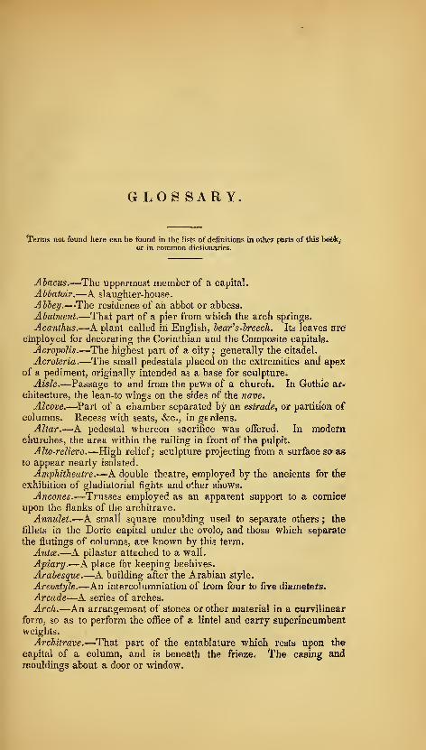
GLOS SAR Y.
Terms not found here can be found in the lists of definitions in other parts of this hdSk^or in common dictionaries.
Abacus.—The uppermost member of a capital.
Abtatoir.—A slaughter-house.
Ahiey.—The residence of ah abbot or abbess.
Abutment.—That part of a pier from which the arch springs.
Acanthus.—A plant called in English, bear's-breech. Its leaves are
ernployed for decorating the Corinthian and the Composite capitals.
Acropolis.—The highest part of a city;generally the citadel.
Acroteria.—The small pedestals placed on the extremities and apexof a pediment, originally intended as a base for sculpture.
Aisle.—Passage to and from the pews of a church. In Gothic ar-
chitecture, the lean-to wings on the sides of the nave.
Alcove.—Part of a chamber separated by an estrade, or partition ofcolumns. Recess with seats, &c., in gerdens.
Altar.—A pedestal whereon sacrifice was offered. In modernchurches, the area within the railing in front of the pulpit.
Alto-relievo.—High relief; sculpture projecting from a surface so asto appear nearly isolated.
Amphitheatre.—A double theatre, employed by the ancients for the
exhibition of gladiatorial fights and other shows.
Ancones.—Trusses employed as an apparent support to a cornice
upon the flanks of the architrave.
Annulet.—A small square moulding used to separate others ; the
fillets in the Doric capital under the ovolo, and those which separate
the flutings of columns, are known by this term.
A7itce.—A pilaster attached to a wall.
Apiary.—A place for keeping beehives.
Arabesque.—A building after the Arabian style.
Areostyle.—An intercolumniation of from four to five diameters.
Arcade—A series of arches.
Arch.—An arrangement of stones or other material in a curvilinear
form, so as to perform the office of a lintel and carry superincumbentweights.
Architrave.—That part of the entablature which rests upon the
capital of a column, and is beneath the frieze* The casing andmouldings about a door or window.

4 APPENDIX.
ArchivoU.—The ceiling of a vault : the uwder surface of an arcfi.
Area.—Superficial measurement. An open space, below the level
of the ground, in front of basement windows.
Arsenal.—A public establishment for the deposition of arms andwarlike stores.
Astragal.—A small moulding consisting of a half-round with a fillet
on each side.
Attic.—A low story erected over an order of architecture. A lowadditional story immediately under the roof of a building.
Aviary.—A place for keeping and breeding birds.
Balcony.—An open gallery projecting from the front of a building.
Baluster.—A small pillar or pilaster supporting a rail.
Balustrade.—A series of balusters connected by a rail.
Barge-course.—That part of the covering which projects over the
gable of a building.
Base.—The lowest part of a wall, column, &c.Basement-story.—That which is immediately under the principal
story, and included within the foundation of the building.
Basso-relievo.—Low relief ; sculptured figures projecting from asurface one-half their thickness or less. See Alto-relievo.
Battering.—See Talus.
Battlement.—Indentations on the top of a wall or parapet.
Bay-window.—A window projecting in two or more planes, and not
forming the segment of a circle.
Bazaar.—A species of mart or exchange for the sale of various ar-
ticles of merchandise.
Bead.—A circular moulding.
Bed-mouldings.—Those mouldings which are between the coronaand the frieze.
Belfry.—That part of a steeple in which the bells are hung : an-
ciently called campanile.
Belvedere.~-An ornamental turret or observatory commanding apleasant prospect.
Bow-window.—A window projecting in curved lines.
Bressummer.—Abeam or iron tie supporting a wall over a gatewayor other opening.
Brick-nogging.—The brickwork between studs of partitions.
Buttress.—A projection from a wall to give additional strength.
Cable.—A cylindrical moulding placed in flutes at the lower part ofthe column.
Camber.—To give a convexity to the upper surface of a beam.Campanile.—A tower for the reception of bells, usually, in Italy,
separated from the church.
Canopy.—An ornamental covering over a seat of state.
Cantalivers.—The ends of rafters under a projecting roof. Piecesof wood or stone supporting the eaves.
Capital.—The uppermost part of a column included between the
shaft and the architrave.

APPENDIX. '5
Caravansera.—In the East, a large public building for the reception
t>f travellers by caravans in the desert.
Carpentry.—(From the Latin, carpentum, carved wood.) That de-
partment of science and art which treats of the disposition, the con-
struction and the relative strength of timber. Th^ first is called de-
scriptive, the second constructive, and the last mechanical carpentry.
Caryatides.—Figures of women used instead of columns to support
an entablature.
Casino.—A small country-house.
Castellated.—Built with battlements and turrets in imitation of an-
cient castles.
Castle.—A building fortified for military defence. A house with
^owers, usually encompassed with walls and moats, and having a don-
jon, or keep, in the centre.
Catacombs.—Subterraneous places for burying the dead.
Cathedral.—The principal church of a province or diocese, wherein
the throne of the archbishop or bishop is placed.
Cavetto.—A concave moulding comprising the quadrant of a circle.
Cemetery.—An edifice or area where the dead are interred.
Cenotaph.—A monument erected to the memory of a person buried
in another place.
Centring.—The temporary woodwork, or framing, whereon anyvaulted work is constructed.
Cesspool,—A well under a drain or pavement to receive the waste-
water and sediment.
Chamfer,—The bevilled edge of any thing originally right-angled.
Chancel.—That part of a Gothic church in which the altar is placed.
Chantry.—A little chapel in ancient churches, with an endowmentfor one or more priests to say mass for the relief of souls out of purga-
tory.
Chapel.—A building for religious worship, erected separately froma church, and served by a chaplain.
Chaplet.—A moulding carved into beads, olives, &c.Cincture.—The ring, listel, or fillet, at the top and bottom of a co-
lumn, which divides the shaft of the column from its capital and base.
Circus.—A straight, long, narrow building used by the Romans for
the exhibition of public spectacles and chariot races. At the present
day, a building enclosing an arena for the exhibition of feats of horse-
manship.Clerestory.—The upper part of the nave of a church above the
roofs of the aisles.
Cloister.—The square space attached to a regular monastery or
large church, having a peristyle or ambulatory around it, covered with
a range of buildings.
Coffer-dam.—A case of piling, water-tight, fixed in the bed of ariver, for the purpose of excluding the water while any work, such as
©, wharf, wall, or the pier of a bridge, is carried up.
Collar-beam.—A horizontal beam framed between two principal
rafters above the tie-beam.
Collonade.—A range of columns.
Columbarium.—A pigeon-house.
6 APPENDIX.
Column.-r-k vertical, cylindrical support under the entablature ofS.n order.
Common-rafters.—-The same as jack-rafters, which see
Conduit.—A long, narrow, walled passage underground, for secret
communication between different apartments. A canal or pipe for the
ponveyance of water.
Conservatory. -rnrA building for preserving curious and rare exotic
plants.
Consoles.—The same as ancones, which see.
Contour.—The external lines which bound and terminate a figure.
Convent.—A building for the reception of a society of religious per-
sons.
Coping.—Stones laid on the top of a wall to defend it from the
weather.
Corbels.—rStqne^ or timbers fixed in a wall to sustain the timbers of
3, floor or roof.
Cornice.—Any moulded projection which crowns or finishes the
part to which it is affixed.
Corona.—That part of a cornice which is between the crown-;
pnoulding and the bed-njouldings.
Cornucopia.—The horn of plenty.
Corridor.-T-kn open gallery or communication to the different apart-
ments of a house.
Cove.—r-k concave moulding.
Cripple-rafters.—The short rafters which are spiked to the hip-rafter
of a roof.
Crockets.—In Gothic architecture, the ornaments placed along the
.angles of pediments, pinnacles, &c,Crosettes.—The same as ancones, which see.
Crypt.—The under or hidden part of a building.
Culvert.—An arched channel of masonry or brickwork, built be?
neath the bed of a canal for the purpose of conducting water under it,
Any arched channel for water underground.
Cupola.-^A. small building on the top of a dome.
Curtail-step.—A step with a spiral end, usually the first of the flight,
Cm*P-s.—srThe pendents of a pointed arch.
Cyma.—vAn ogee. There are two kinds ; the cyma-recta, having
the upper part concave and the lower convex, and the cyma-reversa,
with the upper part convex and the lower concave.
Dado.—The die, or part between the base and cornice of a pedestal.
Dairy.-r-^An apartment or building for the preservation of milk, andJhe manufacture of it into butter, cheese, dsc.
Dead-shoar.—A piece of timber or stone stood vertically in brick-
Tvork, to support a superincumbent weight until the brickwork whichjis to carry it has set or become hard.
Decastyle.—A building having ten columns in front.
Dentils.—(From the Latin, denies, teeth.) Small rectangular blockg
used in the bed-mouldings of some of the orders.
Diasiyle.—An intercolumniation of three, or, as some say, foup
4ian)eters.
APPENDIX.
Die.—That part of a pedestal included between the base and the
cornice ; it is also called a dado.
Dodecastyle.—A building having twelve columns in front.
Donjon.—A massive tower within ancient castles to which the gar-
rison might retreat in case of necessity.
Dooks.—A Scotch term given to wooden bricks.
Dormer.—A window placed on the roof of a house, the frame being
placed vertically on the rafters.
Dormitory.—A sleeping-room.
Dovecote.—A building for keeping tame pigeons. A columbarium.
Echinus.—The Grecian ovolo.
Elevation.—A geometrical projection drawn on a plane at right an-
gles to the horizon.
Entablature.—That part of an order which is supported by the co-
lumns ; consisting of the architrave, frieze, and cornice.
Eustyle.-^An intercolumniation of two and a quarter diameters.
Exchange.—A building in which merchants and brokers meet to
transact business.
Extrados.—The exterior curve of an arch.
Fagade.—The principal front of any building.
Face-mould—The pattern for marking the plank, out of which hand-
Tailing is to be cut for stairs, &c.Facia, or Fascia.—A flat member like a band or broad fillet.
Falling-mould.—The mould applied to the convex, vertical surface
of the rail-piece, in order to form the back and under surface of the
rail, and finish the squaring.
Festoon.—An ornament representing a wreath of flowers and leaves.
Fillet.—A narrow flat band, listel, or annulet, used for the separa-
tion of one moulding from another, and to give breadth and firmness
to the edges of mouldings.
Flutes.—Upright channels on the shafts of columns.
Flyers.—-Steps in a flight of stairs that are parallel to each other.
Forum.—In ancient architecture, a public market ; also, a place
where the common courts were held, and law pleadings carried on.
Foundry.-r^K building in which various metals are cast into moulds
or shapes.
Frieze.—That part of an entablature included between the archi-
trave and the cornice.
Gahle.—The vertical, triangular piece of wall at the end of a roof,
from the level of the eaves to the summit.
Gain.—A recess made to receive a tenon or tusk.
Gallery.—A common passage to several rooms in an upper story.
A long room for the reception of pictures. A platform raised on co-
lumns, pilasters, or piers.
Girder.—The principal beam in a floor for supporting the binding
and other joists, whereby the bearing or length is lessened.
Glyph.—A vertical, sunken channel. From their number, those in
the Doric order are called triglyphs.

•8 APPENDIX.
Granary.—A building for storing grain, especially that intended to
be kept for a eonsiderabie time.
Groin.—The line formed by the intersection of two arches, which•cross each other at any angle.
Gultce.—The small cylindrical pendent ornaments, otherwise called
drops, used in the Doric order under the triglyphs, and also pendentfrom the mutuli of the cornice.
Gymnasium.—Originally, a space measured out and covered with
sand for the exercise of athletic games; afterwards, spacious buildings
devoted to the mental as well as corporeal instruction of youth.
Hall.—The first large apaitment on entering a house. The public
room of a corporate body. A manor-house.
Ha7n.—A house or dwelling-place. A street or village : henceNottingham, Bucking/mm, &c. Hamlet, the diminutive of ham, is asmall street or village.
Helix.—The small volute, or twist, under the abacus in the Corin-
thian capital.
Hem.—The projecting spiral fillet of the Ionic capital.
Hexastyle.—A building having six columns in front.
Hip-rafter.—A piece of timber placed at the angle made by two ad-
jacent inclined roofs.
Homestall.—A mansion-house, or seat in the country.
Hotel, or Hostel.—A large inn or place of public entertainment. Alarge house or palace.
Hot-house.—A glass building used in gardening.
Hovel.—An open shed.
Hvi.—A small cottage or hovel generally constructed of earthy
materials, as strong loamy clay, &c.
Impost.—The capital of a pier or pilaster which supports an arch.
Intaglio.—Sculpture in which the subject is hollowed out, so that
the impression from it presents the appearance of a bas-relief.
Intercolumniation,—The distance between two columns.
Intrados.—The interior and lower curve of an arch.
Jack-rafters.—Rafters that fill in between the principal rafters of a
roof; called also common-rafters.
Jail.—A place of legal confinement.
Jambs.—The vertical sides of an aperture.
Joggle-piece.—A post to receive struts.
Joists.—The timbers to which the boards of a floor or the laths of a•ceiling are nailed.
Keep.—The same as donjon, which see.
Key-stone.—The highest central stone of an arch.
Kiln.—A building for the accumulation and retention of heat, in or-
der to dry or burn certain materials deposited within it.
King-post.—The centre-post in a trussed roof.
Knee.—A convex bend in the back of a hand-rail. See Ramp.
APPENDIX. 9
Lacianum.—The same as dairy, which see.
Lantern.—A cupola having windows in the sides for lighting anapartment beneath.
Larmier.—-The same as corona, which see.
Lattice.—A reticulated window for the admission of air, rather than
light, as in dairies and cellars.
L£oer-5oard5.—Blind-slats : a set of boards so fastened that theymay be turned at any angle to admit more or less light, or to lap uponeach other so as to exclude all air or light through apertures.
Lintel,—A piece of timber or stone placed horizontally over a door,
window, or other opening.
Listel.—The same as fillet, which see.
Lohhy.—-An enclosed space, or passage, communicating with the
principal room or rooms of a house.
Lodge.—A small house near and subordinate to the mansion. Acottage placed at the gate of the road leading to a mansion.
Loop.—A small narrow window. Loophole is a term applied to the
vertical series of doors in a warehouse, through which goods are de-
livered by means of a crane.
Lvffer-boarding.—The same as lever-boards, which see,
Luthern.—The same as dormer, which see.
Mausoleum^—A sepulchral building—so called from a very cele-
brated one erected to the memory of Mausolus, king of Caria, by his
wife Artemisia.
Metopa.—The square space in the frieze between the triglyphs of
the Doric order.
Mezzanine.—A story of small height introduced between two of
greater height.
Minaret.—A slender, lofty turret having projecting balconies, com-mon in Mohammedan countries.
Minster.—A church to which an ecclesiastical fraternity has beenor is attached.
Moat.—An excavated reservoir of water, surrounding a house, cas-
tle or town.
Modillion.—A projection under the corona of the richer orders, re-
sembling a bracket.
Module.—The semi-diameter of a column, used by the architect as
a measure by which to proportion the parts of an order.
Monastery.—A building or buildings appropriated to the reception of
snonks.
Monopteron.—A circular coUonade supporting a dome without anenclosing walk
Mosaic.—A mode of representing objects by the inlaying of small
•cubes of glass, stone, marble, shells, &c.Mosque.—A Mohammedan temple, or place of worship.
Mullions.—The upright posts or bars, which divide the lights in aGothic window.
Muniment-house.—A strong, fire-proof apartment for the keeping
auad preservation of evidences, charters, seals, &c., called muniments.1*
10 APPENDIX.
Museum.—A repository of natural, scientific and literary, curiosities,
or of works of art.
Mutule.—A projecting ornament of the Doric cornice supposed to
represent the ends of rafters.
Nave.—The main body of a Gothic church.
Newel.—A post at the starting or landing of a flight of stairs.
Niche.—A cavity or hollow place in a wall for the reception of astatue, vase, &c.
Nogs.—Wooden bricks.
Nosing.—The rounded and projecting edge of a step in stairs.
Nunnery.—A building or buildings appropriated for the reception of
Obelisk.—A lofty pillar of a rectangular form.
Octastyle.—A building with eight columns in front.
Odeum.—Among the Greeks, a species of theatre wherein the poets
and musicians rehearsed their compositions previous to the public pro-
duction of them.
Ogee.—See Cyma.Orangery.—A gallery or building in a garden or parterre fronting
the south.
Oriel-window.—^A large bay or recessed window in a hall, chapel, or
other apartment.
Ovolo.—A convex projecting moulding whose profile is the quad-
rant of a circle.
Pagoda.—A temple or place of worship in India.
Palisade.—A. fence of pales or stakes driven into the ground.
Parapet.—A small wall of any material for protection on the sides
of bridges, quays, or high buildings.
Pavilion.—A turret or small building generally insulated and com-prised under a single roof.
Pedestal.—A square foundation used to elevate and sustain a co^
lumn, statue, &c.Pediment.—The triangular crowning part of a portico or aperture
which terminates vertically the sloping parts of the roof; this, iir
Gothic architecture, is called a gable.
Penitentiary.—A prison for the confinement of criminals whosecrimes are not of a very heinous nature.
Piazza.—A square, open space surrounded by buildings. Thisterm is often improperly used to denote a portico.
Pier.—A rectangular pillar without any regular base or capital..
The upright, narrow portions of walls between doors and windows are
known by this term.
Pilaster.—A square pillar, sometimes insulated, but more commonly engaged in a wall, and projecting only a part of its thickness.
Piles.—Large timbers driven into the gi'ound to make a secure-
foundation in marshy places, or in the bed of a river.
Pillar.—A column of irregular form, always disengaged, and aE^
APPENDIX. 11
ways deviating from the proportions of the orders ; whence the distinc-
tion between a pillar and a column.
Pinnacle.—A small spire used to ornament Gothic buildings.
Planceer.—The same as soffit, which see.
Plinth.—The lower square member of the base of a column, pedes-
tal, or wall.
Porch.—An exterior appendage to a building, forming a covered
approach to one of its principal doorways.
Portal.—The arch over a door or gate ; the framework of the gate;
the lesser gate, when there are two of different dimensions at one en-
trance.
Portcullis.—A strong timber gate to old castles, made to slide upand down vertically.
Portico.—A colonnade supporting a shelter over a walk, or ambu-latory.
Priory.—A building similar in its constitution to a monastery or
abbey, the head whereof was called a prior or prioress.
Prism.—A solid bounded on the sides by parallelograms, and on the
ends by polygonal figures in parallel planes.
Prostyle.—A building with columns in front only.
Purlines.—Those pieces of timber which lie under and at right an-
gles to the rafters to prevent them from sinking.
Pycnostyle.—An intercolumniation of one and a half diameters.
Pyramid.—A solid body standing on a square, triangular or poly-
gonal basis, and terminating in a point at the top.
Quarry.—A place whence stones and slates are procured.Quay.—(Pronounced, key.) A bank formed towards the sea or on
the side of a river for free passage, or for the purpose of unloadingmerchandise.
Quoin.—An external angle. See Rustic quoins.
Rahlet, or Relate.—A groove or channel in the edge of a board.Ramp.—A concave bend in the back of a hand-rail.
Rampant arch.—One having abutments of different heights.
Begula.—The band below the tsenia in the Doric order.
Riser.-^ln stairs, the vertical board forming the front of a step.
Rostrum.—An elevated platform from which a speaker addresses anaudience.
Rotunda.—A circular building.
Rubble-wall.—A wall built of unhewn stone.
Rudenture.—The same as cable, which see.
Rustic quoins.—The stones placed on the external angle of a build-ing, projecting beyond the face of the wall, and having their edgesbevilled.
Rustic-work.—A mode of building masonry wherein the faces of the
stones are left rough, the sides only being wrought smooth where theiinion of the stones takes place.
12 APPENDIX.
Salon, or Saloon.—A lofty and spacious apartment comprehendingthe height of two stories with two tiers of windows.
Sarcophagus.—A tomb or cofSn made of one stone.
Scantling.—The measure to which a piece of timber is to be or hasbeen cut.
Scarfing.—The joining of two pieces of timber by bolting or nailing
transversely together, so that the two appear but one.
Scotia.—The hollow moulding in the base of a column, between the
fillets of the tori.
Scroll.—A carved curvilinear ornament, somewhat resembling in
profile the turnings of a ram's hom.Sepulchre.—A grave, tomb, or place of interment.
Sewer.—A drain or conduit for carrying off soil or water from anyplace.
Shaft.—The cylindrical part between the base and the capital of acolumn.
Shoar.—A piece of timber placed in an oblique direction to support
a building or wall.
Sill.—The horizontal piece of timber at the bottom of framing ; the
timber or stone at the bottom of doors and windows.
Sojit—The underside of an architrave, corona, &c. The underside
of the heads of doors, windows, &c.Summer.—The lintel of a door or window ,- a beam tenoned into a
girder to support the ends of joists on both sides of it.
Systyle.—An intercolumniation of two diameters.
Tcenia.—The fillet which separates the Doric frieze from the archi-
trave.
Talus.—^The slope or inclination of a wall, among workmen called
hattering.
Terrace.—An area raised before a building, above the level of the
ground, to serve as a walk.
Tesselated pavement.—A curious pavement of Mosaic work, com-posed of small square stones.
Tetrastyle.—A building having four columns in front.
Thatch.—A covering of straw or reeds used on the roofs of cottages,
barns, &c.Theatre.—A building appropriated to the representation of drama,..c
spectacles.
Tile.—A thin piece or plate of baked clay or other material used for
the external covering of a roof.
Tomb.—A grave, or place for the interment of a human body, in-
cluding also any commemorative monument raised over such a place.
Torus.—A moulding of semi-circular profile used in the bases of
columns.
Tower.—A lofty building of several stories, round or polygonal.
Transept.—The transverse portion of a cruciform church.
Transom.—The beam across a double-lighted window ; if the win-
dow have no transom, it is called a clerestory window.
APPENDIX. 13
Tread.—That part of a step which is included between the face of
its riser and that of the riser above.
Trellis.—A reticulated framing made of thin bars of wood for
screens, windows, &c.Triglyph.—The vertical tablets in the Doric frieze, chamfered on
the two vertical edges, and having two channels in the middle.
Tripod.—A table or seat with three legs.
Trochilus.—The same as scotia, which see.
Truss.—An arrangement of timbers for increasing the resistance to
cross-strains, consisting of a tie, two struts and a suspending-piece.
Turret.—A small tower, often crowning the angle of a wall, &;c.
Tusk—A short projection under a tenon to increase its strength.
Tympanum.—The naked face of a pediment, included between the
level and the raking mouldings.
Underpinning.—The wall under the ground-sills of a building.
University.—An assemblage of colleges under the supervision of asenate, &c.
Vault.—A concave arched ceiling resting upon two opposite paral-
lel walls.
Venetian-door.—A door having side-lights.
Venetian-window.—A window having three separate apertures.
Veranda.—An awning. An open portico under the extended roof
of a building.
Vestibule.—An apartment which serves as the medium of commu-nication to another room or series of i-ooms.
Vestry.—An apartment in a church, or attached to it, for the pre-
servation of the sacred vestments and utensils.
Villa.—A country-house for the residence of an opulent person.
Vinery.—A house for the cultivation of vines.
Volute.—A spiral scroll, which forms the principal feature of the
Ionic and the Composite capitals.
Voussoirs.—Arch-stones
Wainscoting.—Wooden lining of walls, generally in panels.
Water-table.—The stone covering to the projecting foundation or
other walls of a building.
Well.—The space occupied by a flight of stairs. The space left
beyond the ends of the steps is called the well-hole.
Wicket.—A small door made in a gate.
Winders.—In stairs, steps not parallel to each other.
Zophorus.—The same as frieze, which see.
Zystos.—Among the ancients, a portico of unusual length, common-ly appropriated to gymnastic exercises.
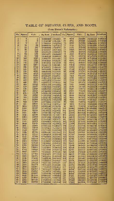
TABLE OF SaUARES, CUBES, AND ROOTS.(From Hutton's Mathematics.)
No. Square. Cube. Sq. Root. CubeRoot. No. Square. Cube. Sq. Root. CubeRoot.
1 1 1 1-0000000 l-OOOOOO 68 4624 314432 8-2462113 4-0816552 4 8 1-4142136 1-250921 69 4761 328509 83066239 4-1015663 9 27 1-7320508 1-442250 70 4900 343000 8-3666003 4-121285
4 16 64 2-0000000 1-537401 71 5041 357911 8-4261498 4-1408185 25 125 2-2360680 1-709976 72 5184 373248 8-4852814 4-1601686 36 216 2-4494897 1-817121 73 5329 389017 85440037 4-1793397 49 343 2-6457513 1-912931 74 5476 405224 8-6023253 4-1983368 64 512 2-8284271 2-000000 75 5625 421875 8-6602540 4-2171639 81 729 30000000 2-080034 76 5776 433976 8-7177979 4-23582410 100 1000 3-1622777 2-154435 77 5929 456533 8-7749644 4-254321
11 121 1331 3-3165243 2-2-23030 78 6084 474552 8-8317609 4-27265912 144 1728 3-4641016 2-239429 79 6241 493039 8-8881944 4-29084013 169 2197 3-6055513 2 351335 80 6400 512000 8-9442719 4-303869
14 196 2744 3-7416574 2-410142 81 6561 531441 9-0000000 4-3i674915 225 3375 3-8729833 2-466212 82 6724 551358 9-0553851 4-344481
16 256 4096 4-0000000 2-519842 83 6839 571787 9-1104336 4-362071
17 289 4913 4-1231056 2-571232 84 7055 592704 9-1651514 4-37951918 324 5832 4-2426407 2-620741 85 7225 614125 9-2195445 4-39683019 361 6859 4-3583989 2-66 S402 86 7396 636055 9-2735185 4-414005
20 400 8000 4-4721350 2-714418 87 7569 658503 9-3273791 4-43104821 441 9261 4-5825757 2-758024 88 7744 681472 9-3808315 4-44796022 484 10648 4-6904153 2-8O2O30 89 7921 704969 9-4339811 4-46474523 529 12167 4-7953315 2-843367 90 8100 729000 9-4S68330 4-481405
24 576 13324 4-8989795 2-884499 91 8281 753571 9-5393020 4-49794125 625 15625 5-0000000 2-924018 92 8464 773688 9-5916630 4-51435726 676 17576 5-0990195 2-962496 93 8649 804357 9-6436508 4-53065527 729 19683 5-1961524 3 000000 94 8836 830534 9-6953597 4-54633628 784 21952 5 2915026 3-036589 95 9025 857375 9-7467943 4-56290329 841 24389 5-3351648 3-072317 96 9216 884736 9-7979590 4-57885730 900 27000 5-4772256 3107232 97 9409 912673 9-8488578 4-594701
31 961 29791 55677644 3-141331 98 9604 941192 9-8994949 4-61043632 1024 32768 5-6568542 3-174802 99 9801 970299 9-9498744 4-62506533 1089 35937 5-7445526 3-207531 100 10000 1000000 100000000 4-64158934 1156 39304 5-8309519 3-230612 101 10201 1030301 10-0498755 4-65700935 1225 42875 5-9160798 3-271066 102 10404 1061208 10-0995049 4-67232936 1296 46656 6 0000000 3 301927 103 10609 1092727 10-1483916 4-68754837 1369 50653 6-0327625 3-332222 104 10816 1124861 10-1980390 4-70265938 1444 54872 6-1644140 3-361975 105 11025 1157625 10-2469508 4-71769439 1521 59319 6-2449980 3-391211 106 11236 1191016 10-2956301 4-73262340 1600 64000 6-3245553 3 419952 107 11449 1225043 10-3140804 4 74745941 1681 68921 6-4031 242 3-448217 108 11664 1259712 10-3923048 4-76220342 1764 74088 6-4807407 3-476027 109 11881 1295029 10-4403065 4-77685643 1849 79507 6-5574335 3-503398 110 12100 1331000 10-4880885 4-79142044 1936 85184 6-6332496 3-530318 111 12321 1357631 10-5356538 4-805895
45 2025 91125 6-708203J 3-556893 112 12544 1404928 10-5330052 4-82028446 2116 97336 6-7823300 3-533048 113 12769 1442897 10-6301458 4-83458847 2209 103323 6-8555546 3-608825 114 12996 1481544 10-6770783 4-84880848 2304 110592 6-9232032 3-634241 115 13225 1520875 10 7238053 4-86294449 2401 117649 7-ooouooo 3-659306 116 13456 1560896 10-7703296 4-87699950 2500 125000 7-0710678 3634031 117 13689 1601613 10-8165533 4-89097351 2601 132551 7-1414284 3-708430 118 13924 1643032 10-8627805 4-90486352 2704 140608 7-2111026 3-732511 119 14161 1685159 10-9087121 4-91868553 2809 148877 7-2^01099 3-756285 120 14400 1723000 10-9544512 4-93242454 2916 157464 7-3181692 3-779763 121 14641 1771561 11-0000000 4-94608755 3025 166375 7-4161935 3-502952 122 14884 1815848 11-0453610 4-95967656 3136 175616 7-4833148 3-825852 123 15129 1860867 11-0905365 4-97319057 3249 185193 7-5193344 3-843501 121 15376 1906624 11-1355-287 4-98663158 3364 195112 7-6157731 3-870877 125 15625 1953125 11-1803399 5-00000059 3481 205379 7-6311457 3-892996 126 15376 2000376 11-2219722 5-01329860 3600 216000 7-7459G67 3-914853 127 16129 2048333 11-2694-277 5-02652661 3721 226981 7-8102197 3-936497 123 16334 2097152 11-3137085 5-039684
62 3844 238328 7-8740079 3-957891 129 16641 21466S9 11-3578167 5-05277463 3969 250047 7-9372539 3-979057 130 16900 2197000 11-4017543 5-065797
64 4U96 262144 8-0000000 4-000000 131 17161 2-248091 11-4-455231 5-078753
65 4225 274625 8-0622577 4-020726 132 17424 2299968 11-4891253 5-091643
66 4356 287496 8-1240334 4-041240 133 17689 2352637 11-5325626 5-104469
67 4489 300763 8-1853528 4-061548 134 17956 2406104 11-5758369 5-117230
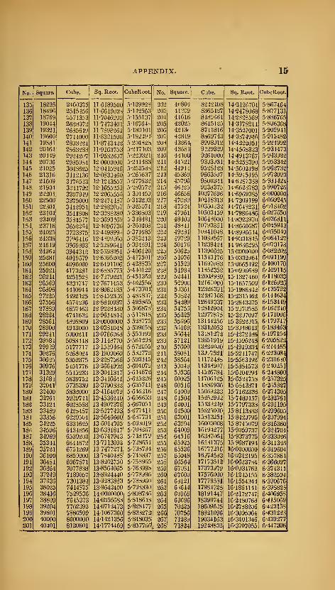
APPENDIX. 15
No. Square. Cube. Sq. Root. CubeKoot. No. Square. Cube. Sq. Root. CubeRoot.
135 18225 2460375 116189500 5-129928 202 4('804 8242408 14-2126704 5-867464
136 18496 2515456 11-661903S 5-142563 203 412C9 8365427 14-2478068 5-877131
137 18769 2571353 11-7046999 5-155137 204 41616 8489654 14-23-28569 5-836765
138 19044 2628072 11-7473401 5 -16764V. 205 42025 8615125 14-3173211 5-896368
139 19321 2635611) 11-7898261 5180101 206 4213.1 8741816 14-3527001 5-905941
140 19600 2744000 11-8321596 5-192494 207 4-.i849 8369743 14-3374946 5-915482
141 19881 2803221 11-8743422 5-204828 203 43-264 8998912 14-4222051 5-924992
142 20164 2363283 11-9163753 5-217103 209 43881 9129329 14-456a323 5-934473
143 20449 2924207 11-95826J7 5-229321 210 44100 9261000 14-4913767 5-943922
144 20736 2985334 12-0000000 5-241483 211 44521 93J3931 14-5253390 5-953342
145 21025 3048625 12-0415946 5-253533 212 44944 95-28123 14-5602198 5-962732
146 21316 3112136 12-0830460 5-265637 213 45369 9663597 14-59-15195 5-972093
147 21609 317I-.523 12-1243557 5-277632 214 45796 9800344 14-6287338 5-981424
148 21904 3241792 12-1655-251 5-289572 215 46225 9933375 14-6623783 5990726149 22201 3307949 12-2065553 5-301459 216 46656 10077696 14-6969385 6-000000
150 22500 3375000 12-2474487 5-313293 217 47089 10218313 14-7309199 6-009245
151 22301 3442951 12-2882057 5-325074 218 475-24 10350^32 14-7648231 6-018462
152 23104 3511808 12-3238280 5-336803 219 47961 10503459 14-7986486 6-027650
153 23409 3531577 12-3693169 5-348431 220 48400 10648000 14-8323970 6-036811
154 23716 3652264 12-4096736 5-360108 221 43-(41 10793861 14-8660687 6-045943
155 24025 3723375 12-449899.. 5-371685 222 49234 loy41048 14-8996644 6-055049
156 24336 3796416 12-4399960 5-383213 223 49729 11039567 14-9331845 6-064127
157 24649 3869393 12-5299641 5-394691 224 50176 11239424 149656295 6-073178
158 24964 3944312 12-5598051 5-406120 225 50625 11390625 15-0000000 6-082202
159 25281 4019579 12-6095202 5-417501 226 51076 11543176 15-0332964 6-091199
160 25600 4096000 12-6491106 5-428835 227 51529 1 1697083 15-0665192 6-100170
161 25921 4173231 12-6335775 5-440122 228 51984 11852352 15-0996639 6-109115
162 26244 4251523 12-7279221 5-451362 229 5-2441 12008939 15-1327460 6-118033
163 26559 4330747 12-7671453 5-462556 230 52900 12167000 15-1657509 6-126925
164 26896 4410944 12-8062485 5-473704 231 53361 12323391 15-1986342 6-135792
165 27225 4492125 12-8452326 5 484807 232 538-24 12487168 15-2315462 6-144634
166 27556 4574296 12-8840987 5-495365 233 54289 12649337 15-2643375 6-153449
167 27839 4657463 12 9228480 5-506878 234 54755 1281-2904 152970585 6-162240
168 28224 4741632 12-9614814 5-517848 235 55225 12977875 15-3297097 6-171006
169 28561 4826809 13-0000000 5-528775 233 55696 13144256 15 3522915 6-179747
170 28900 4913000 13-0384048 5-539658 237 56169 13312053 15-3948043 6-188463
171 29241 5000211 13-0766968 5-550499 238 56644 13481272 15-4272486 6-197154
172 29^)84 5083448 13-1148770 5-561298 239 57121 13651919 15-4596248 6-205822
173 29929 5177717 13-1529464 5-572055 240 57600 13324000 15-4919334 6-214465
174 30276 5268024 13-1909060 5 532770 241 53081 139..7521 15-5241747 6-223084
175 30625 5359375 13-2287566 5-593445 242 58554 14172433 15-5563492 6-234630
176 30976 5451776 13-2664992 5-604079 243 59049 14348907 15-5384573 6-240251
17T 31329 5545233 13-3041347 5-614672 244 59536 145-26784 15-6204994 6-248800
178 31684 5639752 13-3416641 5-625226 245 60025 147061-25 15-65-24753 6-257325
179 32041 5735339 13-3790832 5-635741 246 60516 14836936 15-6843371 6-265327
180 32400 5832000 13-4164079 5-646216 247 6iooy 15039223 15-7162335 6-274305
181 32761 5929741 13-4536240 5-656653 248 61504 15252992 15-7480157 6-282761
182 33124 6023558 13-4907376 5-667051 249 62091 15433249 15-7797333 6-291195
183 33489 6128487 13-5277493 5-677411 250 6-2500 15325000 15-8113383 6-299605
181 33356 6229504 13-5646600 5-637734 251 63001 15313251 15-84-29795 6-397994
185 34225 6331625 13-6014705 5-693019 252 63504 16003008 15-8745079 6-31636018n 34596 6434856 13-6331817 5-703267 253 64009 16194277 15-9059737 6-324704
187 34969 6539203 13-6747943 5-718479 254 64516 16337064 15-9373775 6-333026
188 35344 6644672 13-7113092 5-728654 255 65025 16531375 15 9687194 6-341326
189 35721 6751269 13-7477271 5-738794 256 65536 16777216 16-OOOOOJO 6-349604
190 36100 6859000 13-7840488 5-748897 257 65049 16974593 16-0312195 6 357861191 36481 6967871 13-8202750 5-758965 253 66564 17173512 16-0623734 6-366097
192 36864 7077838 13-8564065 5-763998 259 67031 17373979 16-0934769 6374311193 37249 7189057 13-8924440 5-778996 260 67600 17576000 16-1245155 6-382504
194 37636 7301384 13-9283383 5-783960 261 63121 17779531 16-1554944 6-390676
195 38025 7414875 13-9842400 5-798390 262 6S644 17984723 16-1854141 6-398823
196 38416 7529536 14-0000000 5-808736 263 69169 18191447 16-217-2747 6-406953
197 38809 7645373 14-0355683 5-818643 264 69696 18399744 16-2480763 6-415069
198 39204 7762392 14-0712473 5-823477 265 70225 18609625 16-2738206 6-423153
199 39601 7880599 14-1067360 5-833272 266 70756 18821096 16-3095064 6-431223
200 40000 8000000 14-1421356 5-848035 267 71289 19034163 16-3401346 6-439-277
201 40401 8120601 14-1774469 5-837766 268 71824 19248832 16-3707055 6-447306
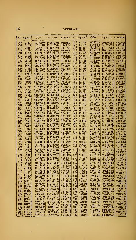
16 APPENDIX
No. Square. Cube. Sq. Root. CubeRoot. No. Square. Cube. Sq Root. CubeRoot
269270
72351 19465109 16-4012195 6-455315 336 112896 37933056 18-3303028 6 95205372900 19633000 16-4316767 6-463304 337 113559 38272753 18 3575598 6-953913
271 73441 19902511 16-4620776 6-471274 338 114244 38614472 18-3847763 6-965820272 73984 20123648 16-4924225 6-479224 339 114921 38958219 18-4119526 6-972683273 74529 20346417 16-52-27116 6-487154 340 115600 39304000 18-4390889 6-979532274 75076 20570824 16-55-29454 6-495065 341 116281 39651821 184661853 6-986.368
275 75625 20796875 16-5331240 6-502957 342 116964 40001688 18-4932420 6-993191276 76176 21024576 16-6132477 6-510830 313 117649 40353607 18-5202592 7-000000
277 76729 21253933 16-6433170 6-518634 344 118336 40707534 18-5472370 7-006796278 77234 21484952 166733320 6-5-26519 345 119025 410636-25 18-5741756 7-013579279 77841 21717639 16-7032931 6-534335 346 119716 41421736 18-6010752 7-020349280 78400 21952000 16-7332005 6-542133 347 120409 41781923 18-6279360 7-027106281 78961 22188041 16-7630546 6-549912 343 121104 42144192 18-6547531 7-033850282 79524 2242576S 16-7923556 6-557672 349 121801 42508549 18-6815417 7-040581283 80089 22665187 16-82-26033 6-565414 350 122500 42875000 18-7082869 7-047299
284 80656 22906334 16-8522995 6-573139 351 123201 43243551 18-7349940 7-054004
285 81225 23149125 16-8319430 6-580844 352 123904 43614208 18-7616630 7-060697286 81796 23393656 16 9115345 6-538532 353 124609 4398 -.977 18-7332942 7-067377287 82369 23639903 16-9410743 6-596202 354 125316 44361864 18-8148877 7-074044283 82944 23387872 16-9705627 6-603S54 355 126025 44733875 18-8414437 7-080699289 83')21 24137569 17-0000000 6-611489 356 126736 45118016 18-8679623 7-087341290 84100 24389000 17-0293864 6-619106 357 127449 45499293 18-8944436 7-093971291 84681 24642171 17-0537221 6-626705 353 128164 45382712 18-9208879 7-100588292 85264 24897088 17-0880075 6-634237 359 128881 46268279 18-947-2953 7-107194293 85849 25153757 17-1172428 6-641852 360 129600 46656000 18-9736660 7-113787294 86136 25412184 17-1464282 6-649400 361 130321 47045381 19-0000000 7-120367295 87025 25672375 17-1755640 6-656930 362 131044 47437928 19-026-2976 7-126936296 87616 25934336 17-2046505 6-664444 363 131769 47832147 19-0525589 7-133492297 8-1209 26198073 17-2336379 6-671940 384 132495 48228544 19-0787840 7-140037298 88804 26463592 17-2626765 6-679420 365 133225 486-27125 19-1049732 7-146569299 89401 26730899 17-2916165 6-686883 366 133956 49027396 19-1311265 7 153090300 90000 27000000 17-3205081 6-694329 367 134639 49430863 19-1572441 7-159599301 90601 27270901 17-3493516 6-701759 368 135424 49835032 19-1833261 7-166096302 91204 27543608 17-3731472 6-709173 369 136161 50243409 19 2093727 7-172531303 91809 27818127 17-4068952 6-716570 370 136900 50653000 19-2353341 7-179054304 92416 28094464 17-4355953 6-723951 371 137641 51064311 19-2613603 7-185516305 93025 28372625 17-4642492 6-731316 372 138384 51478848 19-2373015 7-191966306 93636 23652616 17-4928557 6-733664 373 1391-29 51895117 19-3132079 7-198405307 94249 28934443 17-5214155 6-745997 374 139876 52313624 19-3390796 7-204832308 94864 29218112 17-5499288 6-753313 375 1406-25 52734375 19-3649167 7-211248309 95481 29503529 17 5783953 6-760614 376 141376 53157376 19-3907194 7-217652310 96100 29791000 17-6068169 6-767399 37T 142129 53582633 19-4164878 7-224045311 96721 3(^080231 17-6351921 6-775169 3r8 142884 54010152 19-4422221 7-230427312 97344 30371328 17-6635217 6-782423 379 143641 54439939 19-4679223 7-236797313 97-^69 30664297 17-6918060 6-789661 330 144400 54872000 19-4935387 7-243156311 98596 30959144 17-7200451 6-796834 331 145161 55306341 19-5192213 7-249504315 99225 31255375 17-7482393 6-804092 332 145924 55742968 19-5448203 7-25534131ii 99856 31554496 17-7763388 6-811235 333 146639 56181887 19-5703353 7-262167317 100489 31855013 17-8044933 6-818462 334 147456 56623104 19-5959179 7-263482318 101124 32157432 17-8325545 6-825624 335 148225 57066625 19-6214169 7-274786319 101761 32461759 17-8605711 6-832771 386 148996 57512456 19-6468327 7-231079320 102400 32768000 17-8835438 6-839904 387 149769 57960603 19-6723156 7-287362321 103041 33076161 17-9164729 6-847021 333 150544 58411072 19-6977156 7-293633322 103584 33336248 17-9443584 6-854124 339 151321 58863869 19-7230829 7-299894323 104329 33698267 17-9722008 6-861212 390 152100 59319000 19-7484177 7-306144324 104976 34012224 18-0000000 6-868285 391 152831 59776471 19-7737199 7312383325 105625 34323125 18-0277564 6-875344 392 153664 60236288 19-7989899 7-318611326 106276 34645976 18-0554701 6-882389 393 154449 60693457 19-8242276 7-324829327 106929 34965783 18-0831413 6-889419 394 155236 61162984 19-8494332 7-331037328 107584 35287552 18-1107703 6-896435 395 156025 61629875 19-8746069 7-337234329 108241 35611239 18-1333571 6-903436 396 15-^816 62099136 19-8997487 7-343420330 108900 35937000 18-1659021 6-910423 397 157609 62570773 19-9248588 7-349597
331 109561 36264691 18-1934054 6-917396 398 158404 63044792 19-9499373 7-355762332 110224 36594368 18-2208672 6-924356 399 159201 63521199 19-9749844 7-361918
333 110889 36926037 18-2482376 fi-931301 400 160000 64000000 20-0000000 7-363063
334 111556 37259704 18-2756669 6-933232 401 160801 64481201 20-0249844 7-374198
335 112225 37595375 18-3030052 6-945150 402 161604 64964808 20-0499377 7-330323

APPENDIX. ir
Jfo. Square. Cube. Sq. Root. CubeRoot. No. Square. Cube. Sq. Root. CubeRoot.
403 162409 65450827 20-0748599 7-3ri6437 470 2-z.mo 103323000 21-6794334 7-774980404 16321h 65939264 20-0997512 7-392542 471 221841 104487111 21-7025344 7-7304911405 164025 66430125 20-1246118 7-398636 472 22-2784 105154048 21-7255610 7-785993406 164836 66923416 20-1494417 7-404721 473 223729 105823817 21-7485632 7-791487407 165n49 67419143 20-1742410 7-410795 474 224676 106496424 21-7715411 7-796974408 1H6464 67917312 20-1990099 7-416859 473 225625 107171875 21-7944947 7-802454409 167281 68417929 20-2237434 7-422914 476 226576 107850176 21-8174242 7-807925410 168100 68921000 20-2484567 7-428959 477 227529 108531333 21-8403297 7-813389411 168921 69426531 20-2731349 7-434994 478 223484 109215332 21-8632111 7-818846412 169744 69934523 20-2977831 7-441019 479 229441 109902239 21-8860686 7-824294413 170569 70444997 20-3224014 7-447034 430 230400 110592000 21-908J023 7-829735414 171396 70957944 20-3469899 7-453040 431 231361 111284641 21-9317122 7-835169415 172225 71473375 20-3715488 7-459036 432 232324 111980163 21-9544934 7-84059541f- 173036 71991296 20-3960781 7-465022 483 233289 112678537 21-9772610 7-846013417 173889 72511713 20-4205779 7-470999 434 234256 113379904 22-0000000 7-851424418 174724 73034632 20-4450483 7-476966 435 235225 114084125 22-0227155 7-356823419 175561 73560059 20-4694895 7-482924 486 236196 114791256 22 0454077 7-852224420 176400 74088000 20-4939015 7-488872 437 237169 115501303 22-0680763 7-867613421 177241 74618461 20-5182843 7-494311 488 238144 116214272 22-0907220 7-872994422 178084 75151448 20-3426386 7-500741 439 239121 116930169 2-2- 11334 14 7-878368423 178929 75636967 20-5669638 7-50666
1
490 240100 117649000 22 135943d 7-833735424 179776 76225024 20-5912603 7-512571 491 241031 118370771 22-1535193 7-839095425 180625 76765525 20-6155281 7-518473 492 242064 119095488 22-1810730 7-894447426 181476 77308776 20-6397674 7-524365 493 243049 119823157 22-2036033 7-399792427 182329 77854483 20-6633783 7-530248 494 244036 120553784 22-2261103 7-905129428 183184 78402752 20-6881609 7-536122 495 245025 121-287375 22-2485955 7-910460429 184041 78953589 20-7123152 7-541987 496 246016 122023936 22-2710575 7-915783430 184900 79507000 20-7364414 7-547842 497 247009 122763473 22-2934963 7-921099431 185761 80062991 20-7605395 7-553639 498 243004 123505992 22-315913;) 7-925408432 186624 80621568 20-7846097 7-559526 499 249001 1'24251499 22-3333079 7-931710433 187489 81182737 20-8086520 7-565355 300 230000 125000000 22-3605798 7-9370U3434 188356 81746504 20-8326667 7-571174 501 251001 125751501 22-3330293 7-94-2293
435 189225 82312875 20-8566533 7-576985 502 252004 126506008 22-4053365 7-947574436 190096 82881856 20-8806130 7-582786 503 253009 r27263527 22-42/6615 7-952848
437 190969 83453433 20-9045450 7-583579 504 254016 1280;i4064 22-4499443 7-953114438 191844 84027672 20-9284495 7-594363 505 255025 1-28787625 22-472;i051 7-963374
439 192721 84604519 20-9523-268 7-600133 306 256036 129554216 22-4944438 7-968627
440 193600 85184000 20-9761770 7-605905 507 257049 130323343 22-5166605 7-973373441 194481 8376)121 21-0000000 7-611663 508 253064 13109D512 225330553 7-979112
442 195364 86350388 21-0237960 7-617412 509 259081 13187^2-229 225510283 7-984344
443 196249 86938307 21-0475632 7-623152 510 260100 132651000 22-5331795 7-989570
444 197136 87528384 21-0713J75 7-6-23381 511 261121 133432^31 22-5053091 7-994788
445 198025 88121125 21-0950231 7-634607 512 262144 134217728 22-6274170 8 000000446 198916 88716536 21-1187121 7 640321 513 263169 135003697 22-6495033 8-005205
447 199809 89314623 21-1423745 7-646027 514 264196 135796744 22-6715581 8-0LJ403
448 200704 89915392 21-1660105 7-651725 515 265223 136590873 22-6936114 8-015595
449 201601 90518849 21-1896201 7-657414 516 266256 137383096 227156334 8-020779
450 202500 91125000 21-2132034 7-663094 517 267289 13318^413 22-7376340 8-025957
451 203401 91733851 21-2367606 7-663766 518 268324 138991832 22-7395134 8-031129
452 204304 92345403 21-2802916 7-674430 519 269351 139793359 '22-7815715 8-03629:i
453 205209 92959677 21-2837967 7-680086 520 270400 140608000 22-8U35085 8-041451
454 206116 93576664 21-3072758 7-685733 521 271441 1414-20761 22-8^54244 8-046603
455 207025 941963751 21-3307290 7-691372 522 272434 14-2236648 22-84731b3 8-051748
456 207936 94818816! 21-3541555 7-697002 523 273529 143055667 22-8691933 8 056886457 208849 95443993 21-3773383 7-702625 524 274576 143877824 22-8910463 8-062018
458 209764 96071912 21-4009346 7-708239 525 275625 1447031:i5 22-9128785 8-067143
459 210681 96702579 21-4242333 7-713345 526 276676 145531576 22-9346^99 8•07^^62460 211600 97336000| 21-4476106 7-719443 527 277729 146363183 22-9554806 8077374461 212521 97972181 21-4709106 7-725032 528 •278784 147197952 22-9732506 8 082480462 213444 98611128 21-4941853 7-730614 529 279341 148035389 23 0000000 8-087579463 214369 99252847 21-5174348 7-736183 530 280900 148877000 23-04l7i89 809267;i464 215296 99897344 21-5406592 7-741733
1
531 281961 149721291 23-0434372 8-097759
465 216225 100544625; 21-5633587 7-747311 532 283024 150558768 •23-0631252 8-102839
466 217156 1011946961 21-5370331 7-7328611 533 284089 151419437 23-0867928 8-107913
467 218089 101847563' 21-6101828! 7-758402i534 •285156 152-273304 23 1084400 8-ir2980
468 219024 102503232' 21-6333077 7-763.^361
535 286-225 153130375 23-13i>0570 8-118041
469 219961 1031617091 21-6364078 7-7694621536 287296 133990636 23-1516738
,8-123090
3*

IPPENDIX.
No.
537
Square. Cube. Sq. Root. CubeRoot. No. Square. Cube. Sq. Root. CubeRoot.
288369 154854153 23-1732605 8-123145 604 3n4816 220348864 24-5764115 8-453028533 239444 155720872 23-1948270 8-133187 605 3(16025 221445125 24-5967478 8-457691539 290521 156590819 23-2163735 8-133223 606 3(i7236 222545016 24-6170673 8-462348540 291600 157464000 23-2379001 8-143-253 607 368449 223648543 24-6373700 8-467000541 292681 158340421 23-2594067 8-148276 608 369664 224755712 24-6576560 8-471647542 293764 159220088 23-2308935 8-153294 609 370881 225866529 24-6779254 8-476289543 294849 160103007 23-3023604 8-158305 610 372100 226981000 24 6981781 8-480926544 295936 160989184 23-3233076 8-163310 611 373321 228099131 24-7184142 8-485558545 297025 161878625 23-3452351 8-168309 612 374554 2292209-28 24-7386338 8-490185546 298116 162771336 23-36S6429 8-173:J02 613 375769 230346397 24-7588368 8-494806
547 299209 163667323 23-3880311 8' 178289 614 376996 231475544 24-7790234 8-499423
548 300304 1^566592 23-4093998 8-183269 615 378225 232608375 24-7991935 8-504035
549 301401 165469149 23-4307490 8-188244 616 379456 233744896 24-8193473 8-508642
550 302500 166375000 23-4520788 81932-13 &17 380689 234885113 24-8394847 8-513243
551 303601 167284151 23-4733392 8-198175 618 381924 236029032 24-8596058 8-517840
552 304704 168196608 23-4946802 8-203132 619 383161 237176659 24-8797106 8-522432
553 305809 169112377 23-5159520 8-208082 &20 384400 238328U00 24-8997992 8-527019
554 306916 170031464 23-5372046 8-213027 621 385641 239483061 24-9198716 8-531601
555 308025 170953875 23 5534380 8-217966 622 386884 240641848 24-9399278 8-536178
556 309136 171879616 23-5796522 8-222898 623 38-il29 241804367 24-9599679 8-540750
557 310249 172808693 23-6008474 8-227825 624 389376 242970624 24-9799920 8-545317
558 311364 173741112 23 6220236 8-232746 625 390625 244140625 2^-0600000 8-549880
559 312431 174676879 23-6431808 8-237661 626 391876 245314376 25-0199920 8-554437
560 313600 175616000 23-6643191 8-242&71 627 393129 246491883 25-0399681 8-558990
561 314721 176558481 23-6854386 8-247474 628 394334 247673152 25-0599282 8-563538
562 315844 177504328 23-7065392 8-252371 629 395641 248858189 25-0798724 8-568081
563 316969 178453547 23-7276210 8-2572S3 630 396900 250047000 25-0998008 8-572619
564 318096 179406144 23-7486842 8-262149 631 3:98161 251239591 25-1197134 8-577152
565 319225 180362125 23-7697286 8-267029 632 399424 252435968 25^-1396102 8-581681
566 320356 181321496 23-7907545 8-271904 633 400689 253636137 25-1594913 8-586205
567 321489 182284263 23-8117618 8-276773 634 401956 254840104 25-1793566 8-590724
568 322624 1832504.32 23-8327506 8-281635 635 403225 256047875 25-1992063 8-59.5-238
569 323761 184220009 23-8537209 8-286493 636 404 »96 257259456 25-2190404 8-599748
:570 324900 185193000 23-8746728 8-291344 637 405769 258474853 25-2338539 8-604252
571 326041 186169411 23 8956063 8-296190 638 407044 259694072 25-2586619 8-608753
572 327184 187149248 23-9165215 8-301030 639 408321 260917119 25 2784493 8-613248
573 328329 188132517 23-9374184 8-3J5865 640 409600 262144000 25.2982213 8-617739
574 329476 189119224 23-9532971 8-310694 641 410881 263374721 25-3179778 8-622225
575 33062& 190109375 23-9791576 8-315517 642 412164 264609288 25-3377189 8-626706
576 331776 191102976 24-0000000 8-3203.<5 643 413449 265847707 25-3574447 8-631183
577 332929 192100033 24-0208243 8-325147 644 414736 267089984 25-3771551 8-635655
578 334034 193100552 24-0416306 8-329954 645 416025 268336125 25-3968502 8.640123579 335241 194104539 24-0624188 8-331755 646 417316 269586136 25-4165301 8-644585
580 335400 195112000 24-0831891 8-339551 647 418609 270840023 25-4361947 8-649044
581 337561 196122941 24-1039416 8-344341 648 419904 272097792 25-4558441 8-653497582 333724 197137368 24-1246762 8-349126 649 421201 273359449 25-4754784 8-657946
583 339839 198155287 24-1453929 8-353905 650 422500 274625000 25-4950976 8-662391584 341056 199176704 24-1660919 8-353678 651 423801 275894451 25-5147016 8-666331535 342225 200201625 24-1867732 8-363447 652 425104 277167808 25-5342907 8-671266586 343396 201230056 24-2074369 8-368-209 653 426409 278445077 25-5538647 8-675697587 344569 202262003 24-2230829 8-372967 654 427716 279726264 25-5734237 8-680124588 345744 203297472 24 2487113 8-377719 655 429025 281011375 25-5929678 8-684546589 346921 204336469 24-26932-22 8-382465 656 43j336 282300416 25-6124969 8-688963590 348100 20537i)000 24-2899156 8-337206 657 431649 283593393 25-6320112 8-693376591 349281 206425071 24-3104916 8-391942 658 432964 234890312 25-6515107 8-697784592 350464 207474688 21-3310501 8-396673 6fr9 434281 286191179 25-6709953 8-702188593 351649 208527857 24-3515913 8-401398 660 435600 287496000 25-6904652 8-706588594 352836 209584584 24-3721152 8-406118 661 436921 288804781 25-7099203 8-710983595 354025 210644875 24-3926218 8-410833 662 438244 290117528 25-7293607 8-715373596 355216 211708736 24-4131112 8-415542 663 439569 291434247 25-7487864 8-719760597 356409 212776173 24-4335834 8-420246 664 440896 292754944 25-7681975 8-724141
598 357604 213847192 24-4540385 8-424945 665 442225 294079625 25-7875939 8-728518599 358801 214921799 24.4744765 8-429633 666 443556 295408296 25-8069758 8-732892600 360000 216000000 24-4948974 8-434327 667 444889 296740963 25-8263431 8-737260
601 361201 217081801 24-5153013 8-439010 668 446224 298077632 23-8456960 8-741625
602 362404 218167208 24-5356883 8-443688 669 447561 299418309 25-8650343 8-745985
603 363609 219256227 24-5560583 8-448360 670 448900 300763000 25-8843582 8-750340

APPENDIX. 19
No. Square. Cube. Sq. Root. CubeRoot. No. Square. Cube. Sq. Root. CubeRoot.
671 450241 302111711 25-9035677 8-754691 738 544644 401947-272 27-1661554 9-036886
67a 451584 303464448 25-9229628 8-759033 739 546121 403533419 27-1845544 9-040965
673 452929 304821217 25-9422435 8-763331 740 547600 405224000 27-2029410 9-045042
674 45427b 306182024 25-9615100 8-767719 741 549081 406869021 27-2213152 9-049114
675 455625 307546875 25-9807621 8-772053 742 550564 408518488 27-2396769 9-053183
676 45697(1 308915776 26-0000000 8-776333 743 552049 410172407 27-2580263 9-057248
677 458329 310288733 26-0192237 8-78U708 744 553536 411830784 27-2763634 9-061310
678 459684 311665752 26-0384331 8-785030 745 555025 413493625 27-2946881 9-065368
679 461041 313046839 26.0576284 8-789347 746 556516 415160936 27-3130006 9-06y422
680 462401. 314432000 26-0768096 8-793659 747 558009 416832723 27-3313007 9-073473
681 463761 315821241 26-0959767 8-797968 748 539504 418508992 27-3495337 9-077520
662 465124 317214568 26-1151297 8-802272 749 561001 420189749 27-3678644 9-0ol563
683 466489 318611987 26-1342687 8-806.572 750 562500 421875000 27-3861279 9-085b03
684 467856 320013504 26-1533937 8-810868 751 564U01 423564751 27-4043792 9-08y63a
685 469225 321419125 26-17^5047 8-815160 752 565504 425^59008 27-4226184 9-Oy3672
686 470596 32282885b 26-1916017 8-819447 753 567009 426957777 27-4408455 9-097701
687 471969 3242427^3 26-2106848 8-823731 754 568516 428661064 27-4590604 9-101726
688 473344 3:^5660672 26-2297541 8-828010 755 570025 430368875 27-4772633 9-105748
6s9 474721 3;i7082769 26-2483095 8-832^85 756 571536 432081216 27-4954542 9-109767
690 476100 328509000 26-2678511 8-836550 757 573049 433798093 27-513b33j 9-113782
691 477481 329939371 26-2868789 8-840823 758 574564 435519512 27-53179y8 9-117793
692 478864 331373888 26-3053929 8-845085 759 576081 437245479 27-5499546 9-121801
693 480249 332812557 26-3248932 8-843344 760 577600 438976000 27-5680975 9-125805
i>94 48163b 334255384 26-34387y7 8-853598 761 57yl21 440711081 27-58b2284 9-12a8i/6
695 483025 335702375 26-3628527 8-857849 762 580644 442450728 27-6043475 9-133803
696 48441b 337153536 26-3818119 8-862095 763 582169 444194947 27 6224546 9-137737
697 485809 338608873 26-4007576 8.866337 764 533696 445943744 27-64u549y 9-141787
698 487204 34006839^; 26-4196896 8-870576 765 585z25 447697125 27-658o334 9-145774
699 488601 341532099 26-4386081 8-874810 766 586756 44y4550y6 276707050 9-14975o
700 49UU00 343000000 26-4575131 8-879040 767 588Z89 451217663 27-6947640 9-153737
701 491401 344472101 ii6-476404b 8-883266 768 589824 452984832 27-7128129 9-157714
702 492^04 345948408 26-4952826 8-887488 769 591361 454756609 27-730849:^ 9-16168/
703 494209 347428927 26-514147:^ 8-891706 770 592900 456533000 27-7488739 9-165656
704 495616 3-J8913661 26 5329983 8-895920 771 594441 458314011 27-7663860 9-16902^
705 4»7025 35040ib25 26-5518361 8-900130 772 5y5y84 400099648 27-704^080 9-17358J
706 498436 351895816 26-5706605 8-904337 773 5975Ji9 461889917 27-8028775 9-177544
707 499849 353393243 26-5894716 8-908539 774 599076 463684824 27-8208555 9181501^
708 501264 354894912 26-6082694 8-912737 775 600625 465484375 27-0388218 9-185453
709 502681 356400829 26-6270539 8-916931 776 602176 467288576 27-8567766 9-18940J1
710 504100 357911000 26-645825a 8-921121 777 603729 469097433 27-8747197 9-193347
711 505521 359425431 26-6645833 8-925308 778 605284 470910952 27-8926514 9-197290
712 506944 360944 12S 26-6833281 8-929490 779 606841 472729139 27-9105715 9-201229
713 50«369 362467097 26-7020598 8-933669 78u 6084oO 474552000 27-9284801 9-205164
714 50y7y6 363994344 26-7207784 8-937843 781 60y961 476379541 27-9463772 9-209096
715 511225 365525875 26-7394839 8-942014 782 611524 470211768 27-9642629 9-213025
716 512656 367061696 26-7581763 8-946181 783 613089 480048687 27-982137;: 9-2l695u
717 5140«9 368601813 26-7768557 8-950344 784 614656 481890304 28-ooooouo 9-220873
718 515524 370146232 26-7955220 8-954503 785 616^25 483736625 28 0178515 9-224791
719 516961 37i69495y 26-8141754 8-958658 786 617796 486587656 28-0356915 9-22o707
720 518400 373248000 26-8328157 8-962809 78'/ 619369 487443403 28-0535-203 9-232619
721 519841 374805361 26-8514432 8-966957 788 620944 489303372 28-0713377 9-2^6528
722 521284 370367048 26-8700577 8-971101 789 62Z5-Z1 491169069 28-0891438 9-240435
723 522729 377933067 26-8886593 8-975241 790 6^4100 4y3039000 28- 1069380 9-24433b
724 524176 3795U3424 26-907^481 8-979377 791 625681 494913671 28-12472x2 9-248234
725 5Z5625 .381078125 26-9258240 8-983509 792 627:^64 496793080 28-142494b 9-252130
726 527076 382657176 26-9443872 8-987637 793 628849 498677:^57 28-1602557 9-25b022
727 5285ii9 384240583 26-9629375 8-991762 79* 63J436 500566184 28-1780056 9-259911
728 52i*984 38o82835:!i 26-9814751 8-995883 795 632025 502459875 28-1957444 9-26.>797
729 531441 387420489 :a7-0000000 9-000000 796 633616 504358336 28-2134720 9-2b7b8o
730 532900 389017000 27-0185122 9-004113 79/ 635209 506261573 28-2311884 9-271559
731 534361 390617891 27-0370117 9-008223 798 636804 508169592 28-2488930 9-275435
732 535824 392223168 27-0554985 9-012329 799 638401 510082399 28-2665881 9-279300
733 5a7289 39383^:837 27-0739727 9-016431 800 640000 512000000 28-2842712 9-283170
734 533756' 3;*5446904 27-0924344 9-02055i9 801 641601 513922401 28-3019434 9-5io7044
735 540225' 3t)7065375 27.1108834 y-024624 802 643204 515849608 5{8-319t.045 9-290S07
736 .54169b| 398688256 27-1293199 9-Oaa715 803 644809 51778162/ 28-337254b 9-29476/
737 1 5431691 400315553 27-1477439 9-032802 804 646416 519718464 28-3548938 9-298624

20 APPENDIX.
No. Square. Cube. Sq. Root. CubeRoot. No. Square. Cube. Sq. Root. CubeKoot,
80580680780880981081181;i
813814815816817818819820821822823824825826827828829830831832833834835836837
838839840841842843844845846847848849850851852853854855
648025649636651249652864654481656100657721659314660969662596
52166i)125
52360C616525557943527514112529475129531441000533411731533387328537367797539353144
6642251 541343375665856 543338496
54533^5135473i343254935325955136800055338766155541224855744176755947622456151562556355997656560928356766355256972278957178700057385619157593J368578009537580093704
667489669124670761672400674041675684677329678976680625
6S2276683;»29
6855846872416889 lU
69056169i!224
693889695556697225 582182875698896700569702244703921705600707281708>j64
71064971233671402571571671740971910472080172250072420172590472760y7293167310^5
856 732736
858859860861862863864865866867868869870871
5842770565863762535a84804725905S9719592704000594823321596947688599077107601211584603351125605495736607645423609300192611960049614125000616295051618470208620650477622835964625026375627222016
857 734449 629422793736164 631628712
28 372521928-390139128-407745428 423340828-442925328-46'J4989
28-478061728-495613723-513154928-530685228-548204828-565713728-533211928-600699328-618176028-635642128-653097628-670542428-687976628-705400228-722813228-740215728-757607728-774989128-792360128-809720628-827070628-844410228-861739428-87905822H-8963666
28-9136B4628-930952328-943229728-965496728-982753529-0000000
737881739600741321743044744769746496748225749956751889753424755161756900758641
633839779636056000638277381640503928642735647
29-0172363 9-442870
29-0344623 9-446607
29-0516781 9-450341
9-3024779-3063289-3101759-3140199-3178609-3216979-3255329-3293639-3331929-3370179-3408399-3446579-3484739-352-286
9-3560959-3599029-3637059-3675059-3713029-3750969-378887
9-3826759-3364609-3902429-394021
9-3.77969-4015699-4053399-409105
9-4128699-4166309-4-20.337
9-424142
9-4278H49-4316429-4353839-439131
872873874875876877878879880»81832883834885886887888889890891892893894
29-068883729-086079129-103264429-120439629-137604629-154759529-171904329-189039029-206163729-223278429-240383029-257477729-274562329-291637029-308701829-325756629-342301529-359836529-3768616
644972544 29-3933769647214625 29-4108823649461896 29-4278779651714363 29-4448637 9-535417
653972032656234909658503000660776311
29-4618397 9-53908229-478805929-4957624 9 54640329-5127091 9-550059
9-454079-4578009-4615259-4652479-4639669-4726829-4763969-4301069-4838149-4375189-4912209-4949199-4986159-5023089-505998
9-5U9B859-5133709-517051
9-5207309-5244069-5280799-531750
760384762129763376765623
663J548486653386176676-27624
669921875767376 (^72221376
769129 674526133770884 676836152772641 679151439774400 6814720007761(il 683797841777924 686128968779639 688465387731456 690807104783225 69315412578499r' 695506456786769 697864103733544 700227072790321 702595369792100 704969000793881 707347971 ^., ot^u^oi795664 709732288 29-8663690797449 712121957 29-8831056799236 714516984 29-8998328
895 801025 71691737:896 802816
~ """
897 804609898 806404899 808201900 81OUO0
29-529646129-546573429-563491029-530398929-597297229-614185829-631064829-647934229-664793929-681644229.698484829-715315929-732137529-748949629-765752129-7825452
29-8496231
9.5537129-5573639-561011
9-564656
9-5682989-5719389-5755749-579-208
9-582840
9'C864689-590094
9-5937179-5973379-6009559-6045709-608182
9-542744
9029039049059069079089099109119129139H9159169191891992u921
931932933934935936937938
29 7993239 9-611791
29-8161030 9-615398
29-8328678 9-619002"
9-6226U39-6262029-629797
9-633S919-636931
9-6405699-644154
9-6477379-6513179-654894
9-6584639-6620409-6656109-6691769-6727409-6763.)2
9-679860
29-916550629-933-2591
29-949958329-966648129-983328730-000000030-0166620
30-099833330-1164407
719323136721734273724150792726572699
.-.- ^.v-v.v 729000000901 811801 73143-2701""
813604 733870808 30-0333148815409 736314327 30-0499584817216 738763264 30-0665928819025 741217625 30-0832179820836 743677416822649 746142643824464 748613312826281 751089429828100 753571000829921 756058031831744 758550528 30-1993377 9-697615
833569 761048497 30-2158899 9-701158
835396 763551944 30-2324329 9-704699
837225 766060875 30-2489669 9-708237
839056 768575296840889 771095213842724 773620632844561 776151559846400 778638000
-- 848241 781229961922 850084 783777448923 851929 786330467924 853776 788889024 ov-a^/aooo925 855625 791453125 30-4138127926 857476 794022776 3J-4302481
927 859329 796597983 30-4466747928 861184 799178752 30-4630924929 363041 801765039 30-4795013930 864900 804357O00 30-4959014 3-7bluw""' 866761 806954491 30-512-2926 9-764497
868624 809557568 30-5286750 9-767992
870489 812166237 30-5450487 9-771484
872356 814780504 30-5514136 9-774974
874225 817400375 30-5777697 9-778462
876096 820025356 30-5941171 9-781947
877969 822656953 30-6104557 9-785429
879844 825293672 30-6267857 9-788909
30-1330383 968341730-1496269 9-68697030-1662063 9-690521
30-1827765 9-694069
30-2654919 9-71177230-2820079 9-7153053J-2985148 9-718835
30-3150128 9-722363
30-3315018 9-72588830-3479818 9-7-29411
30-3644529 9-732931
30-3809151 9-73644830-3973683 9-739963
9-7431769-7469869-7504939-7539989-7575009-761000

APPENDIX, 21
No. Square,j
Cube. Sq. Root. CubeRoot.; No. Square. Cube. Sq. Root. CubeRoot.
939 881721 827936019 30-6431069 9-792386 970 940900 912673000 31-1448230 9-8S8933940 883600, 8;W584000 30-6594194 9-795361 971 942841 9154J8611 31-1608729 9 -9023 -13
Ml 8854811 833237621 30-6757233 9-799334 972 94i734 918330048 31-1769145 9-905782
942 887364^ 835396888 30-6920185 9-802304 973 946729 921167317 31-1929479 9-909178
943 889249, 838561807 30-7083051 9-806271: 974 948676 924010424 31-2089731 9-912571
944 891136 8412323S4 30-7245830 9-809736 975 950825 926859375 31-2249900 9-915962
945 8930251 843908625 30-7408523 9-813199 976 952576 929714176 31-2409987 9-919351
946 894916 846590536 30-7571130 9-816659 977 954529 932574833 31-2569992 9-92273 S
947 896809 849278123 30-7733651 9-820117 978 956484 935441352 31-2729915 9-926122
948 898704 851971392 30-7896086 9-823572 979 958441 938313739 31-288^^757 9-929504
949 900601 854670349 30-8058436 9-827025 980 960400 941192000 31-3049517 9-93-2834
950 902500 857375000 30-8220700 9-830476 981 962361 944076141 31-3209195 9-936261
951 904401 860085351 30-8382879 9-833924' 982 964324 946966168 31-3368792 9-93963695-^ 9U6304 862801408 30-8544972 9-837369 983 966289 94986-2087 31-3528308 9-9430U9
953 908209 865523177 30-8706981 9-840813 934 968256 952763904 31-3687743 9-946330
934 910116 868250664 30-8868904 9-844254 985 970225 955671625 31-3847097 9-94;)748
955 912025 870983875 30-9030743 9-847692 986 972196 958535256 31-4006369 9-953114
956 9139361 873722816 30-9192497 9-851128 987 974169 961504803 31-4165561 9956477957 915849 876467493 30-9354166 9-854562 288 976144 964430272 31-4324673 9-959839
958 917764 879217912 30-9515751 9-857993 989 978121 967361669 31-4483704 9-963198
959 919681 881974079 30-9677251 9-861422 990 980100 970299000 31-4642654 9-966555
960 921600 884736000 30-9838668 9-864848 991 982081 973242-271 31-4801525 9-969909
9C1 923521 887503681 31-0000000 9-868272 992 984064 976191488 31-4960315 9-973262
962 925444 890277128 31-0161248 9-871694 993 986049 979146657 31-5119025 9-976612
963 927369 893056347 31-0322413 9-875113 994 988036 982107784 31-5277655 9-979960
964 929296 895841344 31-0483494 9-878530 995 990025 985074875 31-5436206 9-983305
965 931225 898632125 31-0644491 9-881945 996 992016 988047936 31-5594677 9-986649
966 933156 901428696 31-0805405 9-885357J 997 994009 991026973 31-5753068 9-989990
967 935089 904231063 31-0966236 9-888767' 998 996004 994011992 31-5911330 9-993329
968 937024 907039232 31-1126984 9-892175 999 998001 997002999 31-6069613 9-996666
969 938961 909853209 31-1287648 9-895580 1000 1000000^1000000000 31-6227766 10000000
The following rules are for finding the squares, cubes and roots, of
numbers exceeding 1,000.
To find the square of any numher divisible without a remainder.
Rule.—Divide the given number by such a number, from the forego-
ing table, as veill divide it vi^ithout a remainder ; then the square of the
quotient, multiplied by the square of the number found in the table,
will give the answer.
Example.—What is the square of 2,000 ? 2,000, divided by 1,000,
a number found in the table, gives a quotient of 2, the square of which
is 4, and the square of 1,000 is 1,000,000, therefore :
4 X 1,000,000 == 4,000,000 : the Ans.
Another example.—-What is the square of 1,230 ? 1,230, being di-
vided by 123, the quotient will be 10, the square of which is 100, and
the square of 123 is 15,129, therefore :
100 X 15,129 "= 1,512,900 : the Ans.
To find the square of any numher not divisible without a remainder.
Rule.—Add together the squares of such two adjoining numbers, froin
the table, as shall together equal the given number, and multiply the
sum by 2 ; then this product, less 1, will be the answer.
Example.—What is the square of 1,487 ? The adjoining numbers743 and 744, added together, equal the given number, 1,487, and tht.
square of 743 = 552,049, the square of 744 = 553,536, and these
added, = 1,105,585, therefore :
1,105,585 X 2 =- 2,211,170 — 1 = 2,211,169 : the Ans.
To fold the cube of any number divisible without a remainder.
Bule.—Divide the given number by such a number, from the forego-
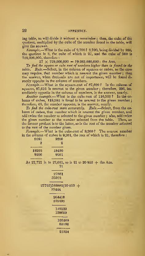
22 APPENDIX.
ing table, as will divide it without a remainder ; then, the cube of the
quotient, multiplied by the cube of the number found in the table, will
give the answer.
Example.—What is the cube of 2,700 ? 2,700, being divided by 900,
the quotient is 3, the cube of which is 27,. and the cube of 900 is
729,000,000, therefore :
27 X 729,000,000 -= 19,683,000,000 : the Ans.
To find the square or cube root of numbers higher than is found in the
table. Rule.—Select, in the column of squares or cubes, as the case
may require, that number which is nearest the given number ; then
the answer, when decimals are not of importance, will be found di-
rectly opposite in the column of numbers.
Example.—What is the square-root of 87,620? In the column of
squares, 87,616 is nearest to the given number ; therefore, 296, im-
mediately opposite in the column of numbers, is the answer, nearly.
Another example.—What is the cube-root of 110,591 ? In the co-
lumn of cubes, 110,592 is found to be nearest to the given number
;
therefore, 48, the number opposite, is the answer, nearly.
To find the cube-root more accurately. Mule.—Select, from the co-
lumn of cubes, that number which is nearest the given number, andadd twice the number so selected to the given number ; also, add twice
the given number to the number selected from the table. Then, as
the former product is to the latter, so is the root of the number selected
to the root of the number given.
Example.—What is the cube-root of 9,200 ? The nearest numberin the column of cubes is 9,261, the root of which is 21, therefore :
9261 92002 2
18522 184009200 9261
As 27,722 is to 27,661, so is 21 to 20-953-f- the Ans.
21
2766155322
27722)580881(20-953 -f55444
264410249498
149120138610
10510083166
21934
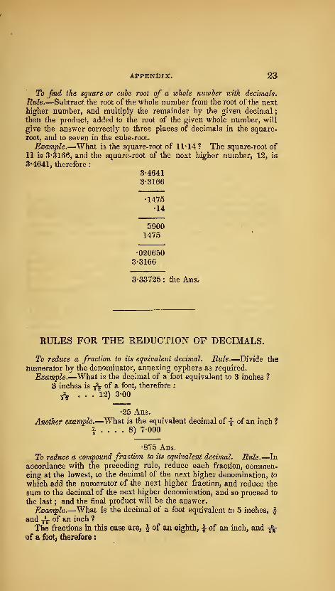
APPENDIX. 23
To find the square or cube root of a whole numler with decimals.
Rule.—Subtract the root of the whole number from the root of the next
higher number, and multiply the remainder by the given decimal
;
then the product, added to the root of the given whole number, will
give the answer correctly to three places of decimals in the square-
root, and to seven in the cube-root.
Example.—What is the square-root of 11-14? The square-root of
11 is 3-3166, and the square-root of the next higher number, 12, is
3'4641, therefore :
3-4641
3-3166
•1475•14
50001475
•0206503-3166
3-33725
:
the Ans.
RULES FOR THE REDUCTIOxN OF DECIMALS.
To reduce a fraction to its equivalent decimal. Rule.—Divide the
numerator by the denominator, annexing cyphers as required.
Example.—What is the decimal of a foot equivalent to 3 inches 1
3 inches is /j ^^ ^ ^°°t, therefore :
ySy ... 12) 3-00
•25 Ans.
Another example.—^What is the equivalent decimal of f of an inch 1
^ .... 8) 7-000
•875 Ans.
To reduce a compound fraction to its equivalent decimal. Rule.—In
accordance with the preceding rule, reduce each fraction, commen-cing at the lowest, to the decimal of the next higher denomination, to
which add the numerator of the next higher fraction, and reduce the
sum to the decimal of the next higher denomination, and so proceed to
the last ; and the final product will be the answer.
Example.—What is the decimal of a foot equivalent to 5 inches, fand -J^ of an inch ?
The fractions in this case are, ^ of an eighth, 4 of an inch, and -f^
of a foot, therefore :
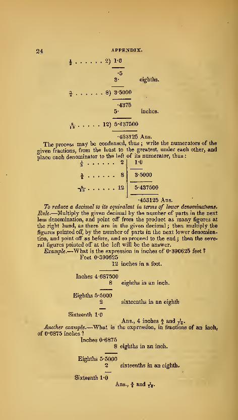
3^ APPENDIX.
i 2) 1-0
•5
3' eighths.
i 8) 3-5000
•43755- inches.
-i- 12) 5-437500
•453125 Ans.
The process may be condensed, thus ; write the numerators of the
given fractions, from the least to the greatest, under each other, and
place each denominator to the left of its numerator, thus
:
2
8
12
1-0
3-5000
5-437500
•453125 Ans.
To reduce a decimal to its equivalent in terms of lower denominations.
Rule.—Multiply the given decimal by the number of parts in the next
less denomination, and point off from the product as many figures at
the right hand, as there are in the given decimal ; then multiply the
figures pointed off, by the number of parts in the next lower denomina-
tion, and point oif as before, and so proceed to the end ; then the seve-
ral figures pointed off at the left will be the answer.
Example.—What is the expression in inches of 0-390625 feet ?
Feet 0-390625
12 inches in a foot.
Inches 4-687500
8 eighths in an inch.
Eighths 5-5000
2 sixteenths in an eighth
Sixteenth 1-0
Ans., 4 inches f and ^^.Another example.—What is the expression, in fractions of an inch,
of 0-6875 inches ?
Inches 0-6875
8 eighths in an inch.
Eighths 5-5000
2 sixteenths in an eighth.
Sixteenth 1*0
Ans., f and ^.

TABLE OF CIRCLES.
(From Gregory's Mathematics.)
From this table may be found by inspection the area or circumfe-
rence of a circle of any diameter, and the side of a square equal to the
area of any given circle from 1 to 100 inches, feet, yards, miles, &c.If the given diameter is in inches, the area, circumference, &c., set
opposite, w^ill be inches ; if in feet, then feet, &c.
Side of Side ofDiam. Area. Circum. equal sq. Diam. Area. Circum. equal sq.
•25 •04908 •78539 •22155 •75 90-76257 33-77212 9-52693•5 •19635 1-57079 •44311 u- 95-03317 34-55751 9-74849•75 •44178 2-35619 •66467 -25 99-40195 35-34291 9-97005
!• •78539 3-14159 •88622 •5 103-85890 36-12831 10-19160•25 1-2^2718 3-92699 1-10778 •75 108-43403 36-91371 10-413165 1^76714 4-71-238 1-32934 12- 113-09733 37-69911 10-63472•75 2-40528 5-49778 1-55089 •25 117^85881 38-48451 10-85627
2- 3-14159 6-23318 l-772i5 •5 122-71846 39-26990 11-07783•25 3-97607 7-06858 1-99401 •75 127^67628 4005530 11-29939•5 4-90873 7-85393 2-21556 13^ 132-73228 40-84070 11-52095•75 5-93957 8-63937 2-43712 •25 137-88646 41-62810 11-74^250
3- 7-06853 9-4-2477 2-65363 •5 143^13881 42-41150 ir96406•25 8-29576 10-21017 2-88023 -75 148-48934 43-19689 12-18562•5 9-62112 10-99557 3-10179 14- 153-93804 43-982-29 12-40717•75 11-04466 11-78097 3-3-2335 •25 159-48491 44-76769 12-62373
4- 12-56637 12-56637 3-54490 •5 165-12996 45-55309 12-85029•25 14-186-25 13-35176 3-76646 •75 170-87318 46-33849 13-07184•5 15-90431 14-13716 3-98802 15^ 176-71458 47-12338 13-29340•75 17-72054 14^92256 4-20957 •25 182-65416 47-90928 13-51496
5- 19-63495 15-70796 4-43113 •5 188-69190 48-69468 13-73651•25 21-64753 16-49336 4-65269 •75 194-8-2783 49-48008 13-95307•5 23-75829 17-27875 4-87424 16^ 201-06192 50-26548 14-1796375 25-96722 18-06415 5-09580 -25 207-39420 51-05088 14-40118
6^ 28-27433 18-84955 5-31736 •5 213-82464 51-83627 14-62274•25 30-67961 19-63495 5-53891 •75 220-35327 52-62167 14-84430•5 33-18307 20-42035 5-76047 17^ 226-98006 53-40707 15-06535•75 35-78470 21-20575 5-98203 •25 233-70504 54-19247 15-28741
1- 33-48456 21-99114 6-20358 •5 240-52818 54-97787 15-50897•25 41-28249 22-77654 6-4-2514 •75 247-44950 55-76326 15-730525 44-17864 23-56194 6-64670 18^ 264-46900 56-54866 15-95208•75 47-17297 24-34734 6-86825 •25 266-58667 57-33406 16-17364% 50-26548 25-13274 7-08981 •5 268-80252 58-11946 16-39519•25 53-45616 2591813 7-31137 •75 276-11654 58-90486 16-61675•5 58-74501 26-70353 7-53292 19-« 283-52873 59-69026 16-83831•75 60-13204 27-48893 7-75448 •25 291-03910 60-47565 17-05986
9^ 63-61725 28-27433 7-97604 -5 298-64765 61-26105 17-28142•25 67-20063 29-03973 8-19759 -75 306-35437 62-04645 17-59298•5 70-83218 29-84513 8-41915 20- 314-15926 62-83185 17-72453•75 74-66191 30-63052 8-64071 •25 322-06233 63-6 17-25 17-94609
10^ 78-53981 31-41592 8-86226 -5 330-06357 64-40264 18-16765•25 82-51589 3-2-20132 9-03382 -75 338-16299 65-18804 18-38920
18-61076•5 86^59014 32-98672 9-30538 21- 346-36059 65-97344
4*
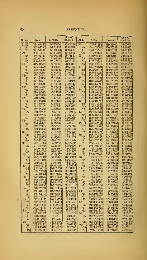
26 APPENDIX.
Side of Side ofDiam. Area. Circum. equal sq. Diam. Area. Cireum. equal sq.
'2i'i5 354^65635 66-75884 18-83232 38- 1134-]1494 119-38052 33-67662•5 363-05030 67-54424 19-05387 -25 1149-08660 120-16591 33-89817•75 371-54241 68-32964 19-27543 •5 1164-15642 120-95131 34-11973
22- 380-13271 69-11503 19^49699 •75 1179-32442 121-73671 34-34129•25 388-82117 69-90043 19-71854] 39- 1194-59060 122-52211 34-56-285
•5 397-60782 70-68583 19-94010 •25 1209-95495 123-30751 34-7844075 406-49263 71-47123 20-16166 •5 1225-41748 124-09290 3500596
23- 415-47562 72^25663 20-38321 •75 1210-97818 124-87830 35-22752•25 424-55679 73-04202 20-60477 40- 1256-63704 125-66370 35-44907•5 433-73613 73-82742 20-82633 -25 1272-39411 126-44910 35-67063•75 443-01365 74-61282 21-04788 -5 1288-24933 127-23450 35-89219
24^ 452-38934 75-39822 21-26944 -75 1304-20273 128-01990 36-11374•25 461-86320 76-18362 21-49100 41- 1320-25431 128-80529 36-33530•5 471-43524 76-96902 21-71255 •25 1336-40406 129-59069 36-55636•75 481-10546 77-75441 21-93411 •5 1352-65198 130-37609 36-77841
25^ 490-87385 78-53981 22-15567 -75 1368-99808 131-16149 36-99997•25 500-74041 79-32521 22-37722 42- 1385-44236 131-94689 37-22153•5 510-70515 80-11061 22-59878 •25 1401-98480 132-73228 37-44308•75 520-76806 80-89601 22-82034 •5 1418-62543 133-51768 37-66464
26- 530-92915 81-68140 23-04190 •75 1435-36423 134-30308 37-88620•25 541-18842 82-46680 23-26345 43^ 1452-20120 135-08348 38-107755 551-54586 83-25220 23-48501 •25 1469-13635 135-87383 38-3-3931
•75 562-00147 84-03760 23-70657 5 1486-16967 136-65928 38-5508727^ 572-55526 84-82300 23-92812 -75 1503-30117 137-44467 38-77242
•25 583-20722 85-60839 24-14968 44- 1520-53084 138-23007 38-99398•5 593-95736 86-39379 24-371241 -25 1537-85869 139-01547 39-21554•75 604-80567 87-17919 24-59279 •5 1556-28471 139-80087 39-43709
28^ 615-75216 87-96459 24-81435 -75 1572-80890 140-58627 3965865•25 626-79682 88-74999 25-03591 45- 1590-43128 141-37166 39-88021•5 637-93965 89-53539 25-25746 •25 1608-15182 142-15706 40-10176
•75 649-18066 90-32078 25-47902 •5 16-25-97054 142-94246 40-3233229^ 660-51985 91-10618 25-70058 •75 1643-88744 143-72786 40-54488
•25 671-95721 91-89153 25-92-213 46^ 1661-90-251 144-51326 40-76643•5 683-49275 92-67698 26-14369 •25 1680-01575 145-29866 40-98799•75 695-12646 93-46238 26-36525 •5 1698-22717 146-08405 41-20955
30^ 706-85834 94-24777 26-58680 •75 1716-53677 146-86945 41-43110•25 71868840 95-03317 25-80836 47^ 1734-94454 147-65485 41-65266•5 730-61664 95-81857 27-02992 •25 1753-45048 148-44025 41-874-32
•75 742-64305 96-60397 27-25147 •5 1772-05460 149-2-3565 42-0957731- 751-76763 97-38937 27-47303 •75 1790-75689 150-01104 42-31733
•25 766-99039 98-17477 27-69459 48- 1809-55736 150-79644 42-53889•5 779-31132 98-96016 27-91614 •25 1828-45601 151-58184 42-76044
•75 791-73043 99-74556 28-13770 •5 1847-45282 152-367-24 42-98200
32- 804-24771 100-53096 28-35926 •75 1866-54782 153-15-264 43-20356
25 816-86317 101-31636 28-58081 49^ 1885-74099 153-93804 43 42511•5 829-57681 102-10176 28-80237 •25 1905-83233 154-72343 43-64667
•75 842-38861 102-88715 2902393 •5 1924-42184 155-50883 43-86823
33^ 855-29859 103-67255 29-24548 •75 1943-90954 156-29423 44-08978
•25 868-30675 104-45795 29-46704 50- 1963-49540 157-07963 44-31134•5 881-41308 105-24335 29-68860 •25 1983-17944 157-96503 44-53290•75 894-61759 106-02875 29-91015 •5 2002-96166 158-65042 44-75445
34- 907-92027 106-81415 30-13171 •75 2022-84205 159-43582 44-9760125 921-32113 107-59954 30-35327 51- 2042-82062 160-22122 45-19757•5 934-82016 108-38494 30-57482 •25 2062-89736 161-00662 45-41912•75 948-41736 109-17034 30-79638 •5 2083-07227 161-79202 45-64068
35^ 962-11275 109-95574 31-01794 -75 2103-34536 162-57741 45-86224•25 975-90630 110-74114 31-23949 52- 2123-71663 163-36281 46-08380•5 989-79803 111-52653 31-46105 •25 2144-18607 164-14821 46-30535•75 1003-78794 112-31193 31-68261 5 2164-75368 184-93361 4652691
36^ 1017-87601 113-09733 31-90416 •75 2185-41947 165-71901 46-74847•25 1032-06227 113-88273 32-12572 53- 2206-18344 166-50441 46-97002•5 1046-34670 114-66813 32-34728 •25 2227-04557 167-28980 47-19158•75 1060-72930 115-45353 32-56883 •5 2248-00589 168-07520 47-41314
37^ 1075-21008 116-23892 32-79039 •75 2269-06438 168-86060 47-63469•25 1089-78903 117-02432 33-01195 54- 2290-22104 169-64600 47-85625•5 1104-46616 117-80972 33-23350 •25 2311-47588 170-43140 48-07781
•75 1119-24147 118^59572 33-45506 •5 2332-82889 171-21679 48-29936
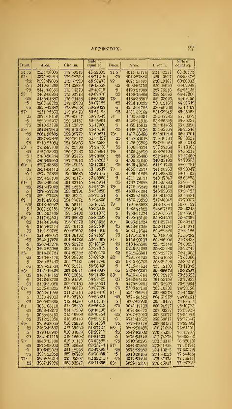
APPENDIX, 27
Side of]
Side ofDiam. Area. Circum. equal sq.
|
Diam. Area. Circum. equal sq.
54-75 2354-28008 172-00219 48-5-2092! 71-5 4015-15176 224-62337 63-3652255- 2375-82944 172-78759 48-74248: -75 4043-27883 225 -409-27 63-58678
•25 2397-47698 173-57-299 48-964031 72- 4071-50407 2-26-19467 63-80833•5 2419-2-2269 174-35839 49-18559 •25 4099-8-2750 226-;)8006 64-02989•75 2441-06657 175-14379 49-40715
i
•5 4128-24909 227-76546 64-3514556- 246300864 175-92918 49-62870 -75 4156-76886 228-55086 64-47300
•25 2485-04887 176-71458 49-850-26' 73- 4185-38681 2-29-336-26 64-69456•5 2507-18728 177-49998 50-07183 -25 4214-10293 230-12166 64-91612•75 2520-42387 178-28538 50-29337 •5 4343-91722 230-90706 65-13767
57- 2551-75863 179-07078 50-51493 •75 4271-82969 231-69245 65-35923•25 2574-19156 179-85617 50-73649 74- 4300-84034 333-47785 65-58079•5 2596-7-2267 180-64157 50-95804 -25 4329-94916 333-36325 65-80234•75 2619-35196 181-42697 51-17960 •5 4359-15615 234-04865 66-02390
58- 264207942 182 21237 51-40116 -75 4388-46132 234-83405 66-24546•25 2664 90505 182-99777 51-6-2271 75- 4417-86466 235-61944 66-46701•5 2687-83886 183-78317 51844-27 •25 4447-36618 236-40484 66-68857
•75 2710-85084 184-56856 52-06583 •5 4476-96588 237-19024 66-9104359- 2733-97100 185-35396 52-28738 •75 4506-66374 237-97564 67-13168
•25 2757- 18933 186-13936 52-50894 76^ 4536-45979 238-76104 67-35334•5 2780-30584 186-92476 52-73050 •25 4566-35400 239-54643 67-57480•75 280392053 187-71016 52-95205 •5 4596-34640 240'33183 67-79635
60^ 2827-43338 188-49555 53-17364 75 4626-43696 241-117-23 68-01791•25 2851-04442 189-28095 53-39517 77^ 4655-63571 341-90263 68-23947•5 2874-75362 190-06635 53-61672 •25 4686-91262 243-68803 68-46103•75 2898-56100 190-85175 53-83828 •5 4717-29771 243-47343 68-68358
61^ 2922-46656 191-63715 54-05984 75 4747-78098 244-25882 68-90414•25 2946-47029 192-42255 54-28139 78- 4778-36242 245 04422 69-12570•5 2970-57220 193-20794 54-50295 -25 4809-04204 245-82962 69-34725•75 2994-77228 193-99334 54-72451 •5 4839-81983 246-61502 69-56881
62^ 3019-07054 194-77874 54-94606 •75 4870-79579 247-40042 69-7903725 3043-46697 195-56414 55-16762 79^ 4901-66993 248-18581 70-01192•5 3067-96157 196-34954 55-38918 •25 4932-74-225 248-97131 70-23348•75 3092-55435 197-13493 55-61073 -5 4963-91274 249-75661 70-45504
63- 3117-24531 197-92033 55-83229 •75 4995-18140 350-34201 70-67659•25 314203444 198-70573 56-05385 80- 5026-54824 251-32741 70-89815•5 3166-92174 199-49113 56-27540 •25 5058-01335 252-11-281 71-11971•75 3191-90722 200-27653 56-49696 -5 5089-57644 252-89820 7r34126
64^ 3216-99087 201-06192 56-71853 •75 5121-23781 253-88360 7r55282•25 3242-17270 201-84732 56-94007 81^ 5152-99735 254-46900 7r78438•5 3267-45270 202'63-272 57-16163 •25 5184-85506 255^25440 72-00593
•75 3293 83088 203-41812 57^38319 •5 5216-81095 256-03980 72-2274965- 3318-30724 204-20352 57-60475 •75 5248-86501 256-82579 73-44905
•25 3343-88176 204-98892 57-82630 82- 5281-01725 257-61059 72-67060•5 3369-55447 205-77431 58-04786 25 531326766 253-39599 72-89216
•75 3395-32534 206-55971 58-26942 -5 5345-616-24 259-18139 73-1137266- 3421-19439 207-34511 58-49097 75 5378^06301 259-96679 73-335-27
•25 344716162 208^ 13051 58-71253 83- 5410-60794 260-75219 73-55683•5 3473-22702 208-91591 58-93409 -25 5443-25105 261-53758 73-77839
•75 3499-39060 209-70130 59-15564 5 5475-99234 262-32298 73-9999467- 3525-65235 210'48570 59-37720 75 5508-83180 263-10838 74-22150
25 3552-01228 211-27210 59-59876 84- 5541-76944 263-89378 74-44306•5 3578-47038 213-05750 59-82031 -25 5574-80525 264-67918 74-66461
•75 360502665 212-84290 60-04187 •5 5607-93923 265-46457 74-8861768' 3631-68110 213-62930 60-26343 •75 5641-17139 266-24997 75-30773
•25 3658-43373 214-41369 60-48498 85- 5674-50173 267-03537 75-3292875-55084•5 3685-28453 215-19909 60-70654 •25 5707-93023 257-82077
•75 3712-33350 215-98449 60-92810 -5 5741-45692 268-60617 75-7724069^ 3739-28065 21676989 61-14965 •75 5775-08178 269-39157 75-99395
•25 3766-42597 217-55529 61-37121 86- 5808-80481 270-17696 76-21551•5 3793-66947 218-34068 61-59377 •25 5842-62602 270-96236 76-43707•75 3821-01115 219-12608 61-81432 -5 5876-54540 271-74776 76-65362
70- 3848-45100 219-91143 62-03588 •75 5910-56396 272-53316 76-88018•25 3875-98902 220-69683 63-35744 87- 5944 67869 273-31856 77-10174•5 3903-625-22 221-483-28 62-47899 •25 5978-89360 274-10395 77-32329
•75 3931-35959 222-26768 62-70055 -5 6013-20468 274-88935 77-5448571- 3959-19214 223-05307 62-92311 -75 6047-61494 275-67475 77-766-il
•25 3987-12386 223-83847 63-14366 88- 6082-12337 276-46015 77-98796
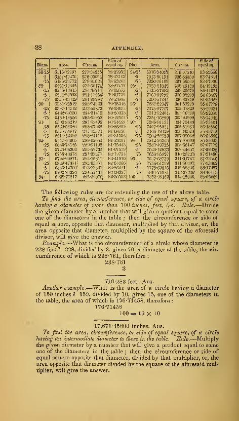
28 APPENDIX.
Side of Side ofDiam. Area. Circum. equal sq. Diam. Ai-ea. Circum. equal sq.
"88^5 6116-72993 277-24555 78-20952 94-25 6976-74097 2;6-0[!510 83-52688•5 6151^43476 278-03094 78-43103 •5 7013-80194 296-88050 83-74344•75 6186-23772 278-81634 78-652C.3 •75 7050-36109 297-66590 83-97000
89- 6221-13885 279-60174 78-87419 95^ 7083-21842 298-45130 84-19155•25 6256-13815 230-33714 79-09575 •25 7325-57992 299-23670 84-41311•5 6291-23563 231-17254 79-31730 •5 7163-02759 300-0-2209 84-03467•75 6326-43129 281-95794 79-53886 •75 7200-57944 300-80749 84-85622
90- 6361-72512 282-74333 79-76042 96^ 7238-22947 301-53239 85-07778•25 6397-11712 233-52873 79-98193 •25 7275-97767 302-37829 85-29934•5 6432-60730 234-31413 80-20353 •5 7313-82404 3U3- 16369 85-52089•75 6463-1S566 285-0^953 80-42509 •75 7351-76859 303-94908 85-74245
91^ 6503-83219 285-83493 80-64669 97^ 7389-81131 304-73448 85-96401
.25 6539-66689 286-67032 80-86820 25 74-27-95221 305-51983 85-18556•5 6575-54977 287-45572 81-03976 •5 7466-19129 306-30523 86-40712•75 6511-53082 288-24112 81-31132 -75 7504-52853 307-09068 86-62868
92- 6347-61005 289-02652 81-53287 98- 7542-96396 307-87603 86-85023•25 66S3-73745 289-31192 81-75443 •25 7581-49755 308-68147 87-07179•5 6720-06303 290-59732 81-97599 •5 7620-12933 309-44637 87-29335•75 6756-43678 291-33271 82-19754 -75 7653-85927 310-232-27 87-51490
93- 6792-90871 292-16811 82-41910 99- 76^7-68739 311-01767 87-73646•25 6829-47831 292-95351 82-64066 -25 77S6-61369 311-80307 87-95802•5 6866-14709 293-73391 82-86221 •5 7775-63816 312-58346 88-17957•75 6902-91354 294-52431 83-08377 •75 7814-76081 313-37336 88-40113
94^ 6939-77817 295-30970 83-30533 100- 7353-98163 314-15926 83-62269
The following rules are for extending the use of the above table.
To find the area, circumference., or side of equal square, of a circle
having a diameter of more than 100 inches, feet, ^c. Rule.—Divide
the given diameter by a number that will give a quotient equal to someone of the diameters in the table ; then the circumference or side of
equal square, opposite that diameter, multiplied by that divisor, or, the
area opposite that diameter, multiplied by the square of the aforesaid
divisor, will give the answer.
Example.—What is the circumference of a circle whose diameter is
228 feet ? 228, divided by 3, gives 76, a diameter of the table, the cir-
cumference of which is 238-761, therefore :
238-761
3
716-283 feet. Ans.Another example.—What is the area of a circle having a diameter
of 150 inches ? 150, divided by 10, gives 15, one of the diameters in
the table, the area of which is 176-71458, therefore :
176-71458
100 =- 10 X 10
17,671-45800 inches. Ans.To find the area, circumference, or side of equal square, of a circle
"having an intermediate diameter to those in the table. Rule.—Multiply
the given diameter by a number that will give a product equal to someone of the diameters in the table ; then the circumference or side of
equal square opposite that diameter, divided by that multiplier, or, the
area opposite that diameter divided by the square of the aforesaid mul-tiplier, will give the answer.
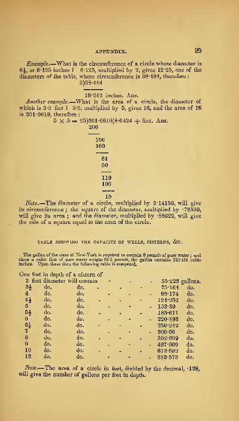
APPENDIX. 2d
Example.—What is the circumference of a circle whose diameter is
6J, or 6-125 inches ? 6-125, multiplied by 2, gives 12-25, one of the
diameters of the table, whose circumference is 38-484j therefore
:
2)38-484
19-242 inches. Ans.Another example.—What is the area of a circle, the diameter of
which is 3-2 feet ? 3-2, multiplied by 5, gives 16, and the area of 16
is 201-0619, therefore :
5 X 5 — 25)201-0619(8-0424 + feet. Ans.
200
106
100
6150
119100
19
Note.—The diameter of a circle, multiplied by 3-14159, will give
its circumference ; the square of the diameter, multiplied by -78539,
will give its area ; and the diameter, multiplied by -88622, will give
the side of a square equal to the area of the circle.
TABLE SHOWING THE CAPACITY OF WELLS, CISTERNS, &C.
The gallon of the state of New-York is required to contain 8 pounds of pure water ; andsince a cubic foot of pure water weighs 62-5 pounds, the gallon contains 221-184 cubicinches. Upon these data the following table is computed.
One foot in depth of a cistern of
3 feet diameter will contain
H do. do.
4 do. do.
4i do. do.
5 do. do.
H do. do.
6 do. do.
6i do. do.
7 do. do.
8 do. do.
9 do. do.
10 do. do.
12 do. do.
55-223 gallons,
75-164 do.
98-174 do.
124-252 do.
153-39 do.
185-611 do.
220-893 do.
259-242 do.
300-66 do.
392-699 do.
497-009 do.
613-592 do.
883-573 do.
Note.—The area of a circle in feet, divided by the decimal, -128,
will give the number of gallons per foot in depth.
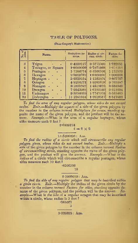
TABLE OF POLYGONS.
(From Gregory's Mathematics.)
Multipliers for Radius of cir- Factors for
12; -S areas. cum. circle. sides.
3 Trigon 0-4330127 0-5773503 1-732051
4 Tetragon, or Square 1-0000000 0-7071068 1-4142145 Pentagon - 1-7204774 0-8506508 1-175570
6 Hexagon 2-5980762 1-0000000 1-000000
7 Heptagon - 3-6339124 1-1523824 0-867767
8 Octagon 4-8284271 1-3065628 0-765367
9 Nonagon - 6-1818242 1-4619022 0-68404010 Decagon 7-6942088 1-6180340 0-61803411 Undecagon 9-3656399 1-7747324 0-563465
12 Dodecagon - 11-1961524 1-9318517 0-517638
To find the area of any regular polygon, whose sides do not exceed
twelve. Rule.—Multiply the square of a side of the given polygon bythe number in the column termed Multipliers for areas, standing op-
posite the name of the given polygon, and the product will be the an-
swer. Example.—What is the area of a regular heptagon, whosesides measure each 2 feet ?
3-6339124
4 = 2X2
14-5356496: Ans.
To find ike radius of a circle which vjill circumscribe any regular
polygon given, whose sides do not exceed twelve. Rule.—Multiply a
side of the given polygon by the number in the column termed Radius
of circumscribing circle, standing opposite the name of the given poly-
gon, and the product will give the answer. Example.—What is the
radius of a circle which will circumscribe a regular pentagon, whosesides measure each 10 feet 1
•8506508
10
8-5065080 : Ans.
To find the side of any regular polygon that may be inscribed within
a given circle. Rule.—Multiply the radius of the given circle by the
number in the column termed Factors for sides, standing opposite the
name of the given polygon, and the product will be the answer. Ex-ample.—What is the side of a regular octagon that may be inscribed
within a circle, whose radius is 5 feet ?
•765367
5
3-826835: Ans.
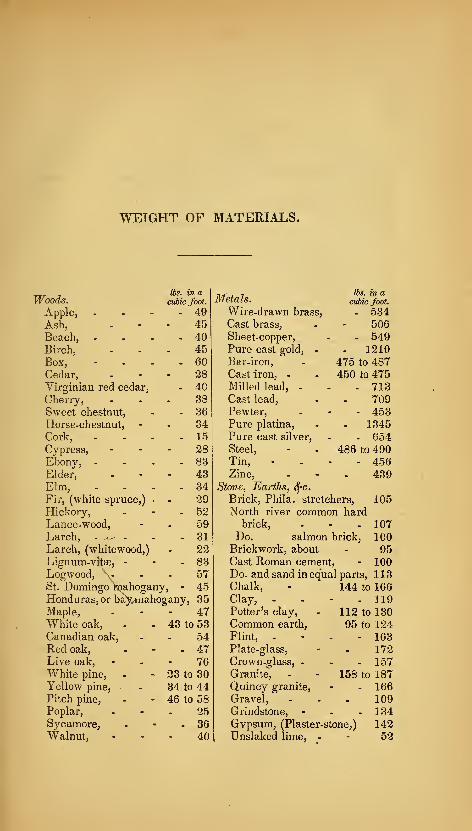
WEIGHT OF MATERIALS.
Woods.His. in acubic foot. Metals.
lbs. in acubic foot.
Apple, . . - - 49 Wire-drawn brass. . 534Ash, - 45 Cast brass, 506
Beach, ... . 40 Sheet-copper, - 549Birch, . 45 Pure cast gold, - - 1210Box, . 60 Bar-iron, 475 to 487Cedar, . 28 Cast iron, - 450 to 475Virginian red cedar, . 40 Milled lead, - - 713Cherry, . 38 Cast lead. 709Sweet chestnut. . 36 Pewter, - 453Horse-chestnut, . 34 Pure platina, - 1345Cork, . 15 Pure cast silver, - 654Cypress, - 28 Steel, 486 to 490Ebony, - - 83 Tin, - 456Elder, - 43 Zinc, 439Elm, . 34 Stone, Earths, SfC.
Fir, (white spruce,) • . 29 Brick, Phila. stretchers, 105Hickory, . 52 North river common hardLance-wood, . 59 brick. - 107Larch, - . - . 31 Do. salmon brick, 100Larch, (whitewood,) . 22 Brickwork, about 95Lignum-vitse, - - 83 Cast Roman cement, - 100Logwood, \- - 57 Do. and sand in equal parts, 113St. Domingo mahogany, - 45 Chalk, 144 to 166Honduras, or ba)^mahogany, 35 Clay, - . - 119Maple, - 47 Potter's clay, 112 to 130White oak. 43 to 53 Common earth. 95 to 124Canadian oak, . 54 Flint, - - 163Red oak. . 47 Plate-glass, 172Live oak. - 76 Crown-glass, - - 157White pine, 23 to 30 Granite, 158 to 187Yellow pine, 34 to 44 Quincy granite, - 166Pitch pine, 46 to 58 Gravel, 109Poplar, . 25 Grindstone, - - 134Sycamore, - 36 Qvpsum, (Plaster-stone,) 142W^alnut, - 40 Dnslaked lime, . 52
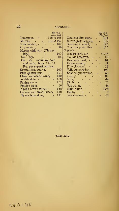
325 APPENDIX.
Cbs. in a lbs. in acubic foot. cubic foot.
Limestone, - - 118 to 198 Common blue stone. 160Marble, - - 161 to 177 Silver-gray flagging. - 185New mortar, - - - 107 Stonework, about. 120Dry mortar. 90 Common plain tiles. - 115Mortar with hair, (Plaster- Sundries.
ing,) .... 105 Atmospheric air. - 0-075
Do. dry, 86 Yellow beeswax, - - 60Do. do. including lath Birch-charcoal, - 34and nails, from 7 to 11 Oak-charcoal, - 21
lbs. per superficial foot. Pine-charcoal, 17
Crystallized quartz. 165 Solid gunpowder, - - 109Pure quartz-sand, 171 Shaken gunpowder. 58Clean and coarse sand, 100 Honey, - 90Welsh slate, - 180 Milk, 64Paving stone, 151 Pitch, - - 71Pumice stone. 56 Sea-water, 64Nyack brown stone, - 148 Rain-water, - - 62-5
Connecticut brown stone, 170 Snow, 8
Nyack blue stone, 171 Wood-ashes, - - 58
THE END.
%\


Related Documents