BRITISH SULPHUR PUBLISHING PRESENTS NITROGEN '2000 Vienna, Austria 12 - 14 March, 2000 THE ADVANTAGES DERIVED FROM AMMONIA AND UREA PLANT REVAMPING TECHNOLOGY BY A SINGLE SOURCE by Ermanno Filippi and Federico Zardi AMMONIA CASALE S.A. / UREA CASALE S.A. Lugano, Switzerland paper/conf/amm/meetings/Nitrogen2000/paper

Welcome message from author
This document is posted to help you gain knowledge. Please leave a comment to let me know what you think about it! Share it to your friends and learn new things together.
Transcript
BRITISH SULPHUR PUBLISHING PRESENTS
NITROGEN '2000 Vienna, Austria
12 - 14 March, 2000
THE ADVANTAGES DERIVED FROM AMMONIA AND
UREA PLANT REVAMPING TECHNOLOGY BY A SINGLE SOURCE
by Ermanno Filippi and Federico Zardi AMMONIA CASALE S.A. / UREA CASALE S.A.
Lugano, Switzerland
paper/conf/amm/meetings/Nitrogen2000/paper
Members of CASALE Group
ABSTRACT
The CASALE Group is the only engineering group in the field which can avail of proprietary technology to upgrade both ammonia and urea plants in single or combined projects. Our double know-how is to the benefit of the Clients who own plants producing both ammonia and urea as they can use our combined technology to their advantage. This paper presents the approach taken by AMMONIA CASALE S.A. and UREA CASALE S.A. to revamp ammonia and urea plants in order to reduce the energy consumption and/or increase their production capacity with a minimum investment cost and the highest benefits.
This approach is based on a number of new technologies developed on purpose by the CASALE companies, which are illustrated. The paper also describes the CASALE experience in implementing their technologies focused on those projects involving the revamp of both ammonia and urea plants. 1. INTRODUCTION AMMONIA CASALE S.A. of Switzerland is an independent engineering company that has been operating worldwide for more than 77 years in the field of ammonia and methanol plants. In the early thirties the CASALE share of total world ammonia production (1 million t/y at that time) was about 60 %; but in the early eighties it was only 8 % of the total 95 million t/y world production. Today, thanks mostly to the revamping of synthesis units, CASALE's share of total world ammonia production has increased again up to 33% of 130 million t/y world production. More recently the range of products has been enlarged, entering also in the field of urea and formaldehyde plants. For that purpose the Company has been split in four, AMMONIA CASALE S.A., UREA CASALE S.A., METHANOL CASALE S.A. and CASALE CHEMICALS S.A., each one taking care of the relevant processes. All four companies are fully owned by CASALE HOLDING S.A. The common targets of the CASALE Companies gain substance from the sale of:
• licenses for the exploitation of technologies • engineering services • equipment and materials • complete plant units • technical assistance services
UREA CASALE has been active in the urea field since 1985, first as AMMONIA CASALE and from 1991 as an independent company.
Members of CASALE Group
_______________________3_______________________ NITROGEN '2000
Vienna, Austria, 12 – 14 March, 2000
From the very beginning, the activity of the company has been concentrated on revamping existing urea plants. Thanks to the revamping activity with the use of innovative technologies, UREA CASALE was able to enter the market and, in only a little more than 10 years, gain a total world urea production share of 24% of today's 96 million tons of urea world production. AMMONIA AND UREA CASALE are at the present time leading licensors of the ammonia and urea technologies. The following international companies are Ammonia CASALE’s and Urea CASALE's licensees:
• Lurgi Germany • Chiyoda Corporation Japan • ICI Katalco U.K. • Linde AG Germany • Technip France • Ube Industries Ltd. Japan • Fluor Daniel Canada • Ube Industries Ltd. Japan
Thanks to a team of very skilful people, most of them with a long experience in the field, AMMONIA CASALE and UREA CASALE developed several innovative and very competitive technologies to revamp ammonia and urea plants becoming world leaders in fertilizer plant revamping. In the current situation, with a constantly increasing demand of fertilizers and economical uncertainty, there is, in fact, a high demand for plant upgrading which can give additional capacity at a cost lower than through new plants construction. AMMONIA CASALE and UREA CASALE, like all companies of the group, share a common management with common engineering, with top experts in both fields, and project management groups. Because of this unique characteristic, CASALE is the only company world-wide that can offer, availing of both ammonia and urea technologies, integrated packages for revamping both types of plants with the same efficiency of a single company and without the difficulties due to the presence of two different engineering companies working in the same plants. But the most outstanding characteristic of all the CASALE Companies is their common philosophy of developing new technologies in their field of operation and to market these new technologies.
Members of CASALE Group
_______________________4_______________________ NITROGEN '2000
Vienna, Austria, 12 – 14 March, 2000
The general approach of CASALE to plant revamping is to upgrade the reaction section in order to increase its efficiency, rather than just adding additional equipment. Most of the technologies have been developed to accomplish this goal and have the unique characteristic of being applicable to plants originally designed according to practically any kind of process. This CASALE philosophy enables overcoming existing plant constraints with the smallest effort by applying new ideas and technology, thus reducing the number of items to be replaced to a minimum and the man-hours as well. Based on these ideas, CASALE has developed a number of solutions, which are illustrated in this paper, to revamp ammonia and urea plants for capacity increase and energy efficiency improvements. These are the technologies used by CASALE to make combined revamping of ammonia and urea plants. 2. REVAMPING OF AMMONIA PLANTS 2.1 PRE-REFORMING REACTOR TECHNOLOGY The pre-reforming reactor proposed by AMMONIA CASALE is designed according to the well-known axial-radial technology for catalyst beds. The advantages of using this technology for pre-reforming reactors are: • the low pressure drop achievable • the use of small size catalyst • the lower operating temperature of the vessel wall when the reaction is exothermic The low pressure drop is an important energy saving feature and helps the compressors reach higher capacities in case of revamping. When there is no natural gas compressor, if the pressure of the gas is close to the reforming pressure, it is important to minimize the DP in all equipment, especially the added ones, to enable capacity increases without having to install a natural gas blower. The small size catalyst has two advantages in comparison with the large size one: • a higher sulfur pick-up, that means a longer life, since sulfur is the main poison; • a greater activity. This means that, with respect to the larger size catalyst, it is possible to reduce the catalyst volume to achieve the same life or to attain a longer life with the same volume. The lower operating temperature of the vessel wall is due to the fact that the feed gas is colder than the product one in the case of exothermic reaction, and this helps to avoid metallurgical problems due to the high operating temperatures.
Members of CASALE Group
_______________________5_______________________ NITROGEN '2000
Vienna, Austria, 12 – 14 March, 2000
Regarding the operation of an axial-radial pre-reformer, it is to be noted that the temperature profile in the catalyst bed can be measured and followed easily, thanks to the presence of thermocouples in different positions along the radial direction in the bed. Also catalyst loading and unloading is very easy, as the axial-radial bed is completely open on the top granting an easy access to the bed even for small diameter vessels, while for unloading there are drop out pipes provided at the bottom. This new technology will be on stream late this year in the Ultrafertil plant in Cubatao, Brazil, as part of a revamping project to increase the capacity from 450 MTD to 800 MTD while reducing the energy consumption. This plant is based on refinery off-gas, the composition of which changes quite often. As a consequence the primary reforming run is also unsteady, requiring the use of very high steam to carbon ratio to protect the reforming system from a possible sudden increase in the carbon content of the feedstock. In these conditions the choice of installing a pre-reformer appeared to be natural, in fact, the two main consequences of its installation are: a) stabilisation of the composition of the gas entering the primary reformer; b) reduction of the duty of the primary reformer. Point A) The first point is due to the fact that all hydrocarbons entering the pre-reforming are cracked down to methane, and some reforming reaction takes also place. The product is, therefore, methane plus some CO, CO2 and hydrogen, steam always being present. Point B) The second point is because the reforming reaction taking place in the pre-reformer is not occurring in the primary reformer. Thanks to the pre-reformer installation, it is, therefore, possible to operate the primary reformer smoothly, with stable operating conditions, to reduce the steam carbon ratio to the primary reformer, as the only feed gas is methane plus steam, CO, CO2 and hydrogen, it is possible to use the natural gas type catalyst that is more active, and to increase the reforming capacity. 2.2 Primary Reformer modification
In ’94, due to the rise of methanol prices and to the low price of ammonia, a large ammonia producer in Russia, namely TOAZ, asked Methanol CASALE to study the possibility to transform one of the 3 GIAP AM 76 ammonia plants into one methanol plant keeping the same production capacity. At the end of ’95 TOAZ decided not to transform one of the existing ammonia plants, but to build a new methanol plant, using as many as existing pieces of equipment possible in its warehouse, originally designed for the eighth ammonia plant.
Members of CASALE Group
_______________________6_______________________ NITROGEN '2000
Vienna, Austria, 12 – 14 March, 2000
A new methanol plant with a capacity of 1350 MTPD (1477 STPD) was designed by Methanol CASALE S.A. taking into account TOAZ's requirements not only to maximise the use of the equipment present at site, but also to maximise the manufacturing of the new equipment inside the C.I.S. countries that was done under CASALE's supervision and responsibility. There are two main features of the new methanol plant: 1. the redesign of the existing ammonia reformer in order to meet the requirement of a
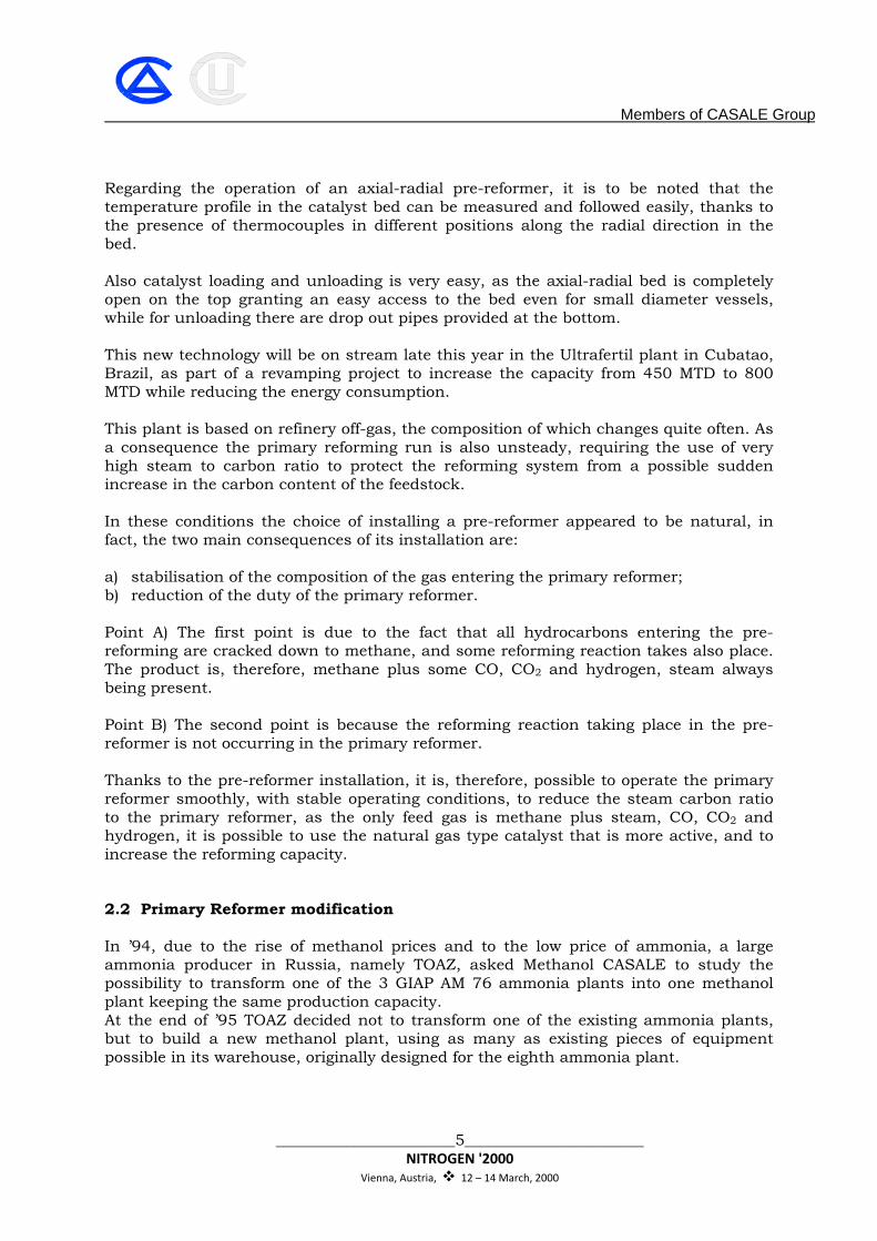
new methanol reformer; 2. the new horizontal methanol converter. In this paper only the transformation of the primary reformer is presented. 2.2.1 Steam Reforming Revamping The process scheme of the GIAP ammonia reformer, which is very similar to a Kellogg, is detailed in fig. 1 together with the convection section.
Fig. 1: Existing Reformer Process
Scheme
In order to reach the guaranteed 1360 MTD methanol, the new reformer configuration required the process design modifications as per Fig. 2.
Members of CASALE Group
_______________________7_______________________ NITROGEN '2000
Vienna, Austria, 12 – 14 March, 2000
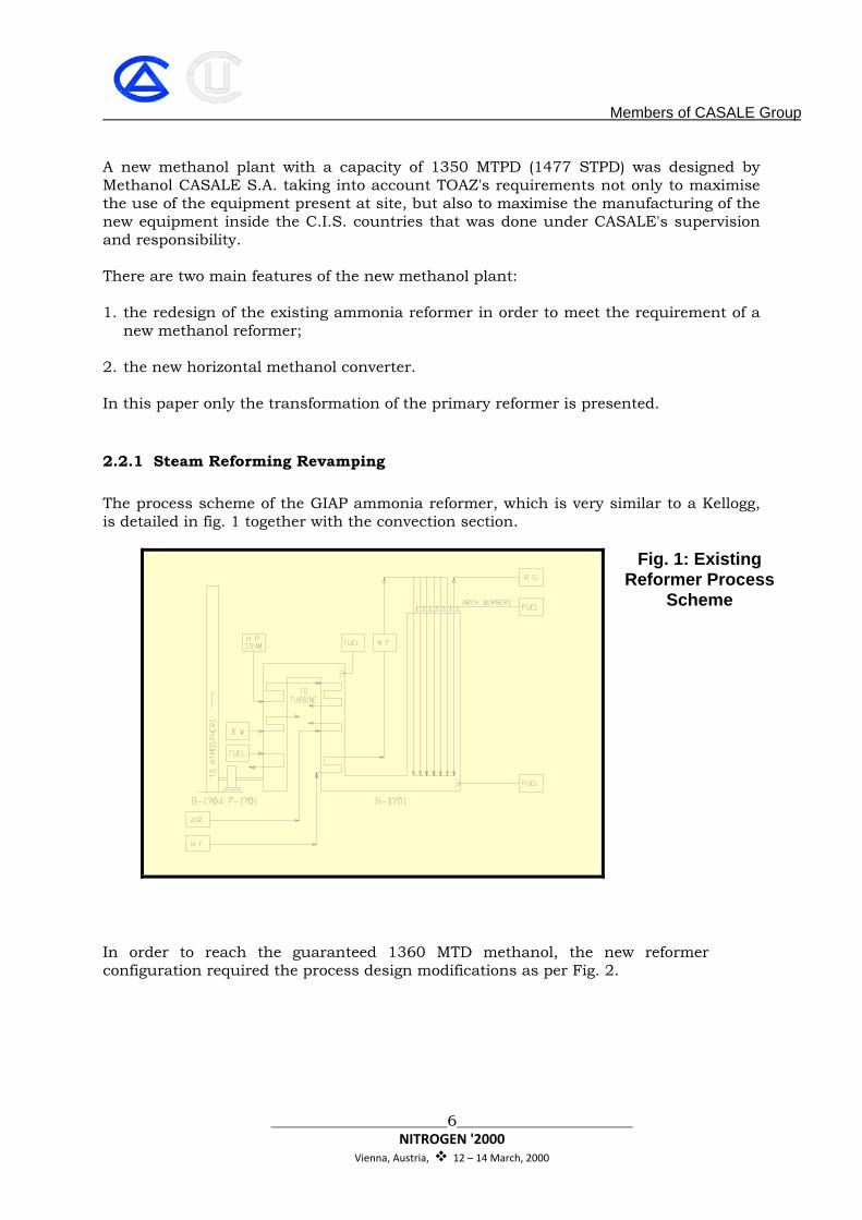
Fig. 2: Retrofitted Reformer Process Scheme
The main revamping features were the following: • Increase of reforming catalyst quantity from 20,8 m3 to 37,6 m3 by changing
catalyst tubes; • Increase of radiant heat liberation from 170'000'000 kcal/h to 227'000'000 kcal/h
by modification of roof burners; • Addition of one BFW heater/boiler convection coil; • Addition of one natural gas preheater convection coil; • Utilization of existing air preheater convection coil to heat MP process steam; • Addition of inline de-superheater between 1st and 2nd stage H.P. steam
superheaters to control the temperature at H.P. turbine inlet. 2.2.2 New Catalytic Tubes In order to accommodate the increased heat duty and to increase the volume of the catalyst, new catalytic tubes were designed. The new tubes were increased in diameter from 114 mm to 121 mm and decreased in thickness from 21 mm to 12 mm. The decrease of thickness was possible thanks to the use of new material 25Cr 35NiNb microalloy, which has proven its reliability in industrial application in the last ten years. 2.2.3 Increase of Burners Heat Liberation The existing burners were designed for a total heat liberation of 188'000'000 kcal/h, while the new required heat liberation is 227'000'000 kcal/h. Therefore, the existing burners were simulated in the new conditions to check if they were suitable for the new capacity and if the new flame did not impinge on the catalytic tubes.

Members of CASALE Group
_______________________8_______________________ NITROGEN '2000
Vienna, Austria, 12 – 14 March, 2000
The check revealed that only the burner nozzle had to be resized and replaced for the new conditions.
2.2.4 Modification of Convection Section The new process design of the methanol plant has required the following retrofitting of the reformer convection section: Process steam heater The existing air preheater has been utilised to heat process steam before mixing with natural gas and no modifications were required in this coil. New BFW heater/boiler A new BFW heater has been inserted between the process steam heater and the 2nd stage steam superheater. In this coil the BFW is heated up to boiling point and a part of it is evaporated. H.P. steam desuperheater A new H.P. steam desuperheater was inserted between 1st and 2nd stage steam superheaters to control the steam temperature at inlet of H.P. steam turbine. The desuperheater is characterised by a steam stud with atomiser which produces fine water drops. Natural gas preheater The new natural gas preheater is installed between the 1st stage steam superheater and the BFW preheater.
2.3 SECONDARY REFORMER BURNER
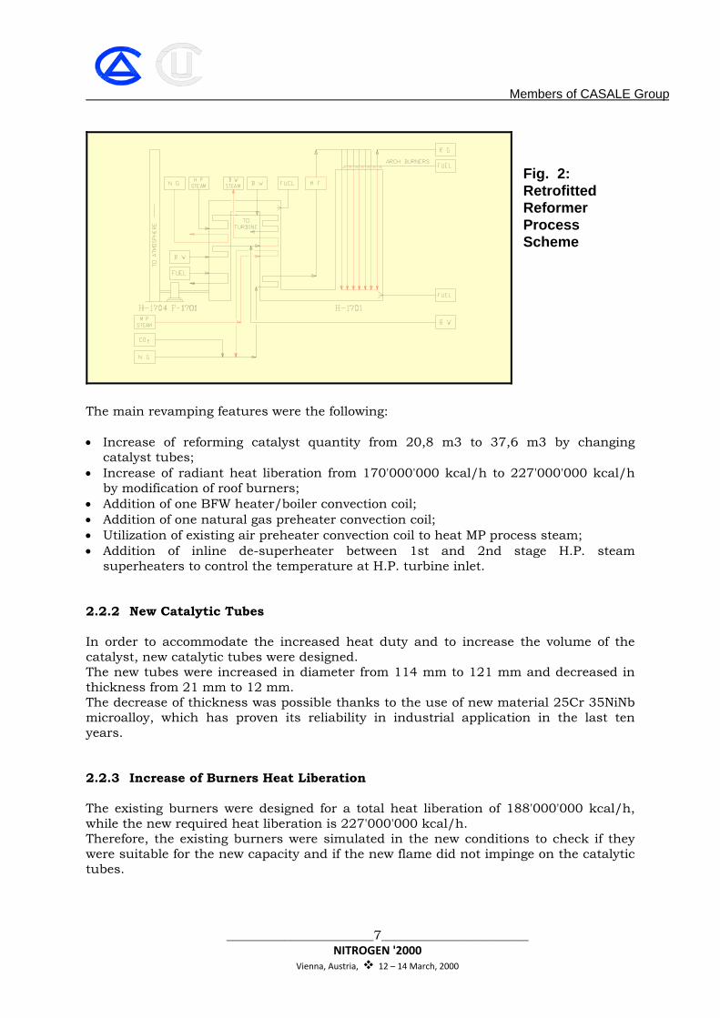
Historically, ammonia plant Secondary Reformers' conventional design was based on a multiple nozzle burner for injecting pre-heated air into the primary reformer effluent gas. In the common design, the burner is placed at the end of the air feed pipe at the top of a conical combustion chamber. The primary reformer gas flows through an annular tube concentric to the air tube. Mixing and combustion take place in the cone and the combustion product flows down into the catalyst bed (Fig 3).
Members of CASALE Group
_______________________9_______________________ NITROGEN '2000
Vienna, Austria, 12 – 14 March, 2000
FIG. 3
The high temperature on the surfaces exposed to the flames for convection and radiation has always caused problems to the burner. With the introduction of the air preheat (600ºC), in order to reduce ammonia plant energy consumption, the burner surface cooling has become one of the major issues in the secondary reformer design. In the last 25 years of conventional design to maintain the burner temperatures within reasonable values, the air was forced to flow in complex paths inside the burner head with high-pressure losses. Non-even temperature and composition distribution of the gas also characterized some old burner designs with temperature hot spots on the catalyst surface and uneven catalyst gas load. In the early ‘70s the flow field and the gas mixing inside the conical chamber were not well understood and the computational fluid dynamics technique, used today for the combustion simulation, were at an early stage of development and not applicable for industrial design.

Members of CASALE Group
_______________________10_______________________ NITROGEN '2000
Vienna, Austria, 12 – 14 March, 2000
Nowadays advanced fluid dynamic simulation techniques are more easily available, and with their utilization, CASALE has developed an innovative design for Secondary Reformer Burners. The burner is a key element in the secondary reformer design, because it mixes the air and primary reformer effluent gases in a diffusion flame. The flame core temperature is very high, often above 2000ºC; consequently heat transfer to the burner from the flame, and the other hot surfaces as well, by radiation and by convection from the recirculating gases must be minimized. Hence, burner design must combine fluid dynamic principle of mixing and combustion processes to maintain a safe operation and a long equipment lifetime. The goal was to develop a simple design capable of withstanding the severe operating conditions in a safe, reliable and cost effective manner. The Computational Fluid Dynamic (CFD) simulations of the velocity, temperature and composition fields inside and outside the burner and in the combustion chamber were performed interfacing a commercial CFD software with ‘in house’ developed combustion subroutines. During the design of the CASALE Advanced Secondary Reformer Burner these engineering aspects were of major importance: • Low pressure losses of both air and primary reformer stream (much lower than
the existing design). • Low temperature of the burner surfaces exposed to the flames. • An almost perfect mixing in the diffusion flame. • Reduced flame length in order to increase the catalyst volume for high load
operations. • Soot free combustion. • Homogeneous gas composition and temperature distribution at catalyst bed
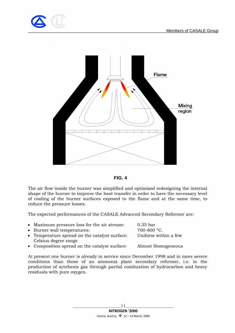
entrance. • Protections of the refractory lining from the flame hot core. The recirculation of the reacted gases protects the refractory and the burner from the hot core and also ensures a homogeneous gas and temperature distribution at the catalyst bed entrance (Fig 4).
Members of CASALE Group
_______________________11_______________________ NITROGEN '2000
Vienna, Austria, 12 – 14 March, 2000
FIG. 4
The air flow inside the burner was simplified and optimized redesigning the internal shape of the burner to improve the heat transfer in order to have the necessary level of cooling of the burner surfaces exposed to the flame and at the same time, to reduce the pressure losses. The expected performances of the CASALE Advanced Secondary Reformer are: • Maximum pressure loss for the air stream: 0.35 bar • Burner wall temperatures: 700-800 ºC. • Temperature spread on the catalyst surface: Uniform within a few Celsius degree range • Composition spread on the catalyst surface: Almost Homogeneous At present one burner is already in service since December 1998 and in more severe conditions than those of an ammonia plant secondary reformer, i.e. in the production of synthesis gas through partial combustion of hydrocarbon and heavy residuals with pure oxygen.
Members of CASALE Group
_______________________12_______________________ NITROGEN '2000
Vienna, Austria, 12 – 14 March, 2000
The burner operates with an average temperature of the main recirculating gases of about 1300ºC, that is 300 to 400ºC over the mean temperature of the secondary reformer recirculation, and after being inspected showed no signs of deterioration whatsoever. The design process parameters have been met in terms of pressure drop and uniformity of temperature and composition in and after the flame, as it is testified by the analysis of the exit gas.
2.7 SHIFT CONVERTERS REVAMPING
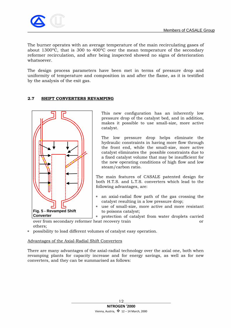
This new configuration has an inherently low pressure drop of the catalyst bed, and in addition, makes it possible to use small-size, more active catalyst. The low pressure drop helps eliminate the hydraulic constraints in having more flow through the front end, while the small-size, more active catalyst eliminates the possible constraints due to a fixed catalyst volume that may be insufficient for the new operating conditions of high flow and low steam/carbon ratio.
The main features of CASALE patented design for both H.T.S. and L.T.S. converters which lead to the following advantages, are: ∗ an axial-radial flow path of the gas crossing the
catalyst resulting in a low pressure drop; ∗ use of small-size, more active and more resistant
to poisons catalyst; ∗ protection of catalyst from water droplets carried
over from secondary reformer heat recovery train or others;
∗ possibility to load different volumes of catalyst easy operation. Advantages of the Axial-Radial Shift Converters
There are many advantages of the axial-radial technology over the axial one, both when revamping plants for capacity increase and for energy savings, as well as for new converters, and they can be summarised as follows:
Fig. 5 - Revamped Shift Converter
Members of CASALE Group
_______________________13_______________________ NITROGEN '2000
Vienna, Austria, 12 – 14 March, 2000
Revamping for capacity increase ∗ no pressure drop limitation due to lower differential pressure within the axial-radial
technology; ∗ no larger catalyst volume required, thanks to the use of smaller catalyst with higher
activity; ∗ longer operation at equilibrium with higher product purity (H2 plants) or higher
production rates (NH3 plants); ∗ longer operation at equilibrium with the consequence of higher plant capacity; ∗ longer catalyst life due to higher catalyst activity and poison resistance;
∗ protection of catalyst from water droplets with the consequence of an extended catalyst lifetime.
Revamping, same capacity ∗ energy saving, thanks to the lower pressure drop; ∗ reduced catalyst volume (30 - 50 %) for the same catalyst life; ∗ same catalyst volume for longer life.
Members of CASALE Group
_______________________14_______________________ NITROGEN '2000
Vienna, Austria, 12 – 14 March, 2000
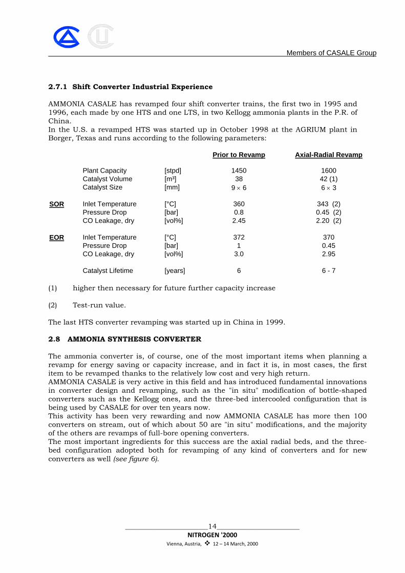
2.7.1 Shift Converter Industrial Experience
AMMONIA CASALE has revamped four shift converter trains, the first two in 1995 and 1996, each made by one HTS and one LTS, in two Kellogg ammonia plants in the P.R. of China. In the U.S. a revamped HTS was started up in October 1998 at the AGRIUM plant in Borger, Texas and runs according to the following parameters:
Prior to Revamp Axial-Radial Revamp
Plant Capacity [stpd] 1450 1600 Catalyst Volume [m³] 38 42 (1) Catalyst Size [mm] 9 × 6 6 × 3 SOR Inlet Temperature [°C] 360 343 (2) Pressure Drop [bar] 0.8 0.45 (2) CO Leakage, dry [vol%] 2.45 2.20 (2) EOR Inlet Temperature [°C] 372 370 Pressure Drop [bar] 1 0.45 CO Leakage, dry [vol%] 3.0 2.95 Catalyst Lifetime [years] 6 6 - 7
(1) higher then necessary for future further capacity increase (2) Test-run value.
The last HTS converter revamping was started up in China in 1999.
2.8 AMMONIA SYNTHESIS CONVERTER The ammonia converter is, of course, one of the most important items when planning a revamp for energy saving or capacity increase, and in fact it is, in most cases, the first item to be revamped thanks to the relatively low cost and very high return. AMMONIA CASALE is very active in this field and has introduced fundamental innovations in converter design and revamping, such as the "in situ" modification of bottle-shaped converters such as the Kellogg ones, and the three-bed intercooled configuration that is being used by CASALE for over ten years now. This activity has been very rewarding and now AMMONIA CASALE has more then 100 converters on stream, out of which about 50 are "in situ" modifications, and the majority of the others are revamps of full-bore opening converters. The most important ingredients for this success are the axial radial beds, and the three-bed configuration adopted both for revamping of any kind of converters and for new converters as well (see figure 6).
Members of CASALE Group
_______________________15_______________________ NITROGEN '2000
Vienna, Austria, 12 – 14 March, 2000
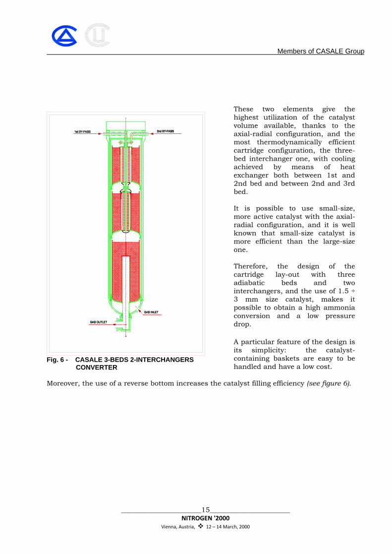
These two elements give the highest utilization of the catalyst volume available, thanks to the axial-radial configuration, and the most thermodynamically efficient cartridge configuration, the three-bed interchanger one, with cooling achieved by means of heat exchanger both between 1st and 2nd bed and between 2nd and 3rd bed. It is possible to use small-size, more active catalyst with the axial-radial configuration, and it is well known that small-size catalyst is more efficient than the large-size one. Therefore, the design of the cartridge lay-out with three adiabatic beds and two interchangers, and the use of 1.5 ÷ 3 mm size catalyst, makes it possible to obtain a high ammonia conversion and a low pressure drop. A particular feature of the design is its simplicity: the catalyst-containing baskets are easy to be handled and have a low cost.
Moreover, the use of a reverse bottom increases the catalyst filling efficiency (see figure 6).
Fig. 6 - CASALE 3-BEDS 2-INTERCHANGERS CONVERTER
Members of CASALE Group
_______________________16_______________________ NITROGEN '2000
Vienna, Austria, 12 – 14 March, 2000
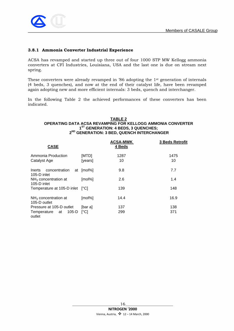
3.8.1 Ammonia Converter Industrial Experience ACSA has revamped and started up three out of four 1000 STP MW Kellogg ammonia converters at CFI Industries, Louisiana, USA and the last one is due on stream next spring. These converters were already revamped in ’86 adopting the 1st generation of internals (4 beds, 3 quenches), and now at the end of their catalyst life, have been revamped again adopting new and more efficient internals: 3 beds, quench and interchanger. In the following Table 2 the achieved performances of these converters has been indicated.
TABLE 2 OPERATING DATA ACSA REVAMPING FOR KELLOGG AMMONIA CONVERTER
1ST GENERATION: 4 BEDS, 3 QUENCHES; 2ND GENERATION: 3 BED, QUENCH INTERCHANGER
CASE
ACSA-MWK
4 Beds
3 Beds Retrofit
Ammonia Production [MTD] 1287 1475 Catalyst Age [years] 10 10
Inerts concentration at 105-D inlet
[mol%] 9.8 7.7
NH3 concentration at 105-D inlet
[mol%] 2.6 1.4
Temperature at 105-D inlet [°C] 139 148
NH3 concentration at 105-D outlet
[mol%] 14.4 16.9
Pressure at 105-D outlet [bar a] 137 138 Temperature at 105-D outlet
[°C] 299 371
Members of CASALE Group
_______________________17_______________________ NITROGEN '2000
Vienna, Austria, 12 – 14 March, 2000
3. REVAMPING OF UREA PLANTS A quick overview of the most advanced UREA CASALE technologies is given, considering the main classes of possible revamping:
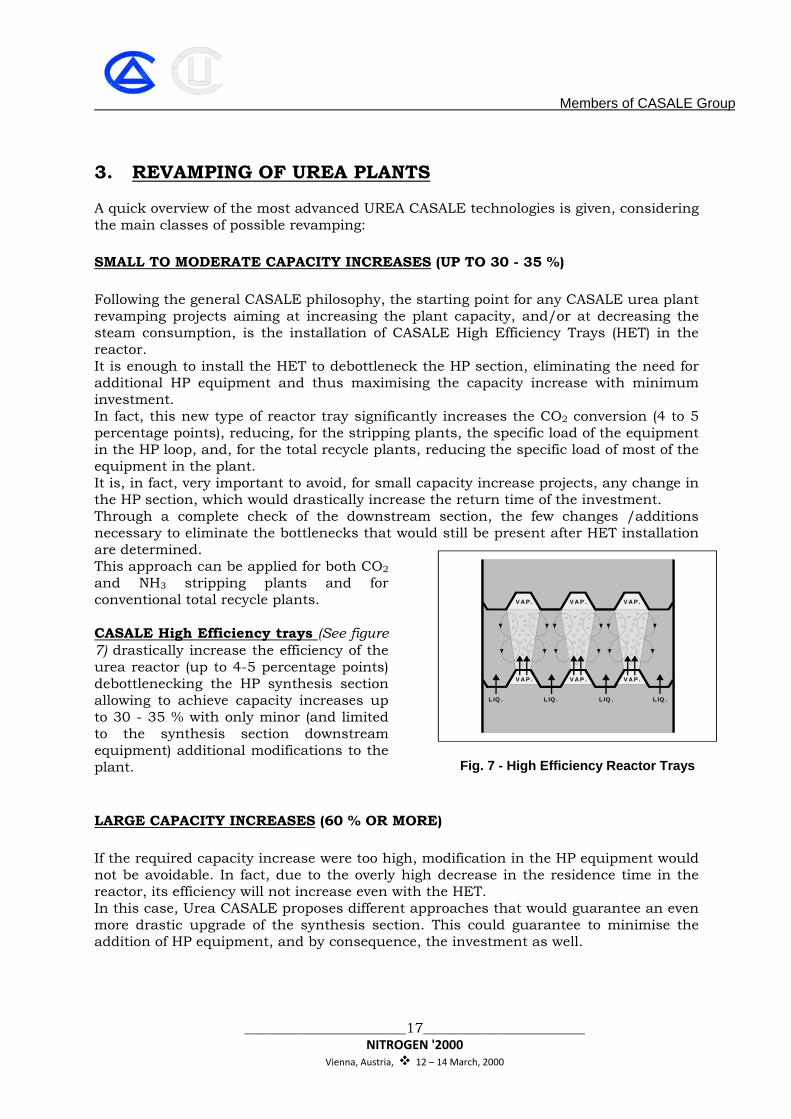
SMALL TO MODERATE CAPACITY INCREASES (UP TO 30 - 35 %) Following the general CASALE philosophy, the starting point for any CASALE urea plant revamping projects aiming at increasing the plant capacity, and/or at decreasing the steam consumption, is the installation of CASALE High Efficiency Trays (HET) in the reactor. It is enough to install the HET to debottleneck the HP section, eliminating the need for additional HP equipment and thus maximising the capacity increase with minimum investment. In fact, this new type of reactor tray significantly increases the CO2 conversion (4 to 5 percentage points), reducing, for the stripping plants, the specific load of the equipment in the HP loop, and, for the total recycle plants, reducing the specific load of most of the equipment in the plant. It is, in fact, very important to avoid, for small capacity increase projects, any change in the HP section, which would drastically increase the return time of the investment. Through a complete check of the downstream section, the few changes /additions necessary to eliminate the bottlenecks that would still be present after HET installation are determined. This approach can be applied for both CO2 and NH3 stripping plants and for conventional total recycle plants. CASALE High Efficiency trays (See figure 7) drastically increase the efficiency of the urea reactor (up to 4-5 percentage points) debottlenecking the HP synthesis section allowing to achieve capacity increases up to 30 - 35 % with only minor (and limited to the synthesis section downstream equipment) additional modifications to the plant.
LARGE CAPACITY INCREASES (60 % OR MORE) If the required capacity increase were too high, modification in the HP equipment would not be avoidable. In fact, due to the overly high decrease in the residence time in the reactor, its efficiency will not increase even with the HET. In this case, Urea CASALE proposes different approaches that would guarantee an even more drastic upgrade of the synthesis section. This could guarantee to minimise the addition of HP equipment, and by consequence, the investment as well.
V A P . V A P .
V A P . V A P .
L IQ .L IQ .L IQ .
V A P .
V A P .
L IQ .
Fig. 7 - High Efficiency Reactor Trays
Members of CASALE Group
_______________________18_______________________ NITROGEN '2000
Vienna, Austria, 12 – 14 March, 2000
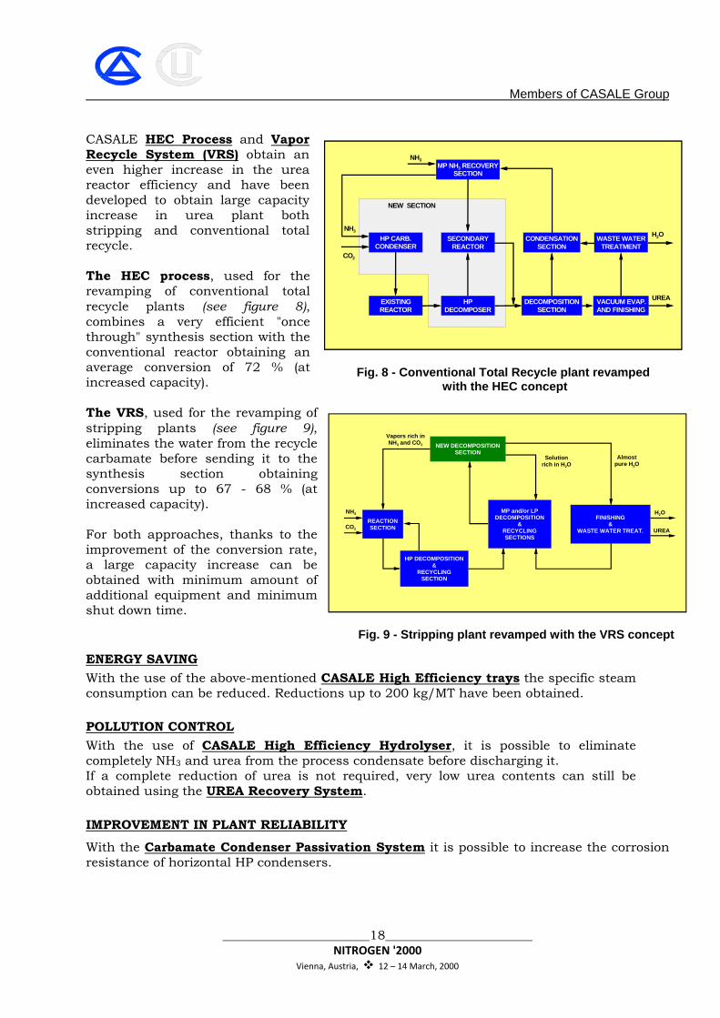
CASALE HEC Process and Vapor Recycle System (VRS) obtain an even higher increase in the urea reactor efficiency and have been developed to obtain large capacity increase in urea plant both stripping and conventional total recycle. The HEC process, used for the revamping of conventional total recycle plants (see figure 8), combines a very efficient "once through" synthesis section with the conventional reactor obtaining an average conversion of 72 % (at increased capacity). The VRS, used for the revamping of stripping plants (see figure 9), eliminates the water from the recycle carbamate before sending it to the synthesis section obtaining conversions up to 67 - 68 % (at increased capacity). For both approaches, thanks to the improvement of the conversion rate, a large capacity increase can be obtained with minimum amount of additional equipment and minimum shut down time. ENERGY SAVING With the use of the above-mentioned CASALE High Efficiency trays the specific steam consumption can be reduced. Reductions up to 200 kg/MT have been obtained.
POLLUTION CONTROL With the use of CASALE High Efficiency Hydrolyser, it is possible to eliminate completely NH3 and urea from the process condensate before discharging it. If a complete reduction of urea is not required, very low urea contents can still be obtained using the UREA Recovery System.
IMPROVEMENT IN PLANT RELIABILITY
With the Carbamate Condenser Passivation System it is possible to increase the corrosion resistance of horizontal HP condensers.
MP NH3 RECOVERYSECTION
SECONDARYREACTOR
HPDECOMPOSER
EXISTINGREACTOR
HP CARB.CONDENSER
CONDENSATIONSECTION
DECOMPOSITIONSECTION
WASTE WATERTREATMENT
VACUUM EVAP.AND FINISHING
UREA
H2O
CO2
NH3
NEW SECTION
NH3
Fig. 8 - Conventional Total Recycle plant revamped with the HEC concept
NEW DECOMPOSITIONSECTION
MP and/or LPDECOMPOSITION
&RECYCLINGSECTIONS
FINISHING&
WASTE WATER TREAT.
HP DECOMPOSITION&
RECYCLINGSECTION
REACTIONSECTION
H2O
UREA
NH3
CO2
Vapors rich inNH3 and CO2
Solutionrich in H2O
Almostpure H2O
Fig. 9 - Stripping plant revamped with the VRS concept
Members of CASALE Group
_______________________19_______________________ NITROGEN '2000
Vienna, Austria, 12 – 14 March, 2000
4. INDUSTRIAL EXPERIENCE The competitiveness and the success of AMMONIA CASALE revamping technologies highlighted above is proven by the fact that they have been applied successfully, or will be applied in a short time, in more the 120 projects worldwide. The competitiveness and the success of UREA CASALE revamping technologies underlined above is proven by the fact that, in the last ten years, over 50 urea plants, with capacities ranging from 250 to 2400 MTD, have been or are being revamped utilizing CASALE technologies. Of these plants, 70 % were originally designed according to stripping technologies. A total of thirty-eight (38) projects involving installation of HET have been carried out or are under completion for plants having capacities ranging from 250 to 2100 MTD. CASALE Revamping Experience using HET Technology We will give now some examples of the application of CASALE technologies to the revamping of both ammonia and urea plants in the factory. Togliatti (Russia) plant Togliatti Azot is a major fertilizer complex in Russia owning seven ammonia plants originally designed according Chemico technology, four plants, and GIAP technology, three plants, and two 1'500 MTD urea plants originally designed according the NH3 stripping process. The four Chemico ammonia plants have been revamped by AMMONIA CASALE in the early ninties, while one of the Giap plants will be revamped this year. At the beginning of the nineties, Toaz asked CASALE to study the revamping of its Urea plants to increase the capacity by 15 %, decreasing the energy consumption and increasing plant reliability. CASALE concluded that the following modifications were required to reach the new capacity:
• Installation of CASALE High Efficiency trays (HET) to increase reactor efficiency. • Replacement of CO2 compressor internals to increase its capacity. • Replacement of the internals of the carbamate pumps. • Replacement of prilling bucket.
In order to reduce the energy consumption and the plant reliability, the following was suggested:
• Installation of a heat recovery section to recover the heat from the MP evaporator vapours using it to evaporate the water from the urea solution.
• Installation of the URS to reduce the urea carry-over from the vacuum evaporator. • Installation of the CCPS to reduce the corrosion of the HP carbamate condenser.
During 1993 and 1994 the above modifications for the capacity increase have been carried out in both plants achieving the 15 % capacity increase. In addition, the following benefits in terms of energy consumption reduction have been obtained:
• the compressor was able to compress 15% more CO2 with the same amount of steam; this means that the steam consumption of the turbine has decreased by 15%.
Members of CASALE Group
_______________________20_______________________ NITROGEN '2000
Vienna, Austria, 12 – 14 March, 2000
• the steam consumption of the stripper has decreased by ab. 200 kg/MT due to the fact that the CO2 conversion in the reactor has increased by ab. 4-5 percentage points.
For the other modifications CASALE has completed the supply, but the erection has not completed yet. From previous experience, the following benefits are expected :
• Saving of about 200 kg/MT of LP steam • decrease of the urea content in the process condensate down to 500 ppm. • drastic reduction of the corrosion in the HP carbamate condenser and increase of its
exchange coefficient allowing to operate the stripper with a lower pressure (few bars) increasing its efficiency.
It is to be mentioned that the CASALE Group, through METHANOL CASALE, is converting one 1350 MTD GIAP NH3 plant into a 1350 MTD methanol plant. Yiuntianhua Yunnan (China) plant Yiuntianhua owns one standard M.W. Kellogg 1000 MTD ammonia plant and one 1'630 MTD urea plant originally designed according the CO2 stripping process. CASALE has revamped the ammonia plant in two steps, first the NH3, converter with in situ modification in 1989, and then in 1995 the HTS and LTS converters. The urea plant has been also revamped by CASALE increasing the capacity by 15% and reducing the energy consumption. The changes necessary to reach this increase in capacity were the installation of the High Efficiency Trays, of a new passivation system, of the Urea Recovery System and the modification to the CO2 compression system. The revamped urea plant is in operation since '94. The steam consumption has been also reduced by 150 MT/D. Gorlovka (Ukraine) plant Stirol owns two 1350 MTD ammonia plants at Gorlovka originally designed according to the Toyo and GIAP processes respectively and two production lines, one originally designed according to the CO2 stripping process to produce 1'000 MTD and a second one originally designed according to the Tecnimont process to produce 1'500 MTD. AMMONIA CASALE revamped the GIAP plant ammonia converter with in-situ modification in 1998. UREA CASALE had first revamped both urea plants in order to reduce energy consumption introducing its HET. In a second step, the CO2 stripping plant had been revamped, increasing the capacity by 35%. In addition to the HET previously installed, the following modifications were necessary to reach 1350 MTD :
• few additional pieces in the LP and vacuum sections • a new prilling bucket • modification to the existing HP pumps (some new internals) • supply of refurbished CO2 compressor (compressor supplied by CASALE after
refurbishing). The revamped line has just been started up reaching the new design capacity.
Members of CASALE Group
_______________________21_______________________ NITROGEN '2000
Vienna, Austria, 12 – 14 March, 2000
Agrium’s Carseland (Canada) plant Agrium’s Carseland, Alberta, Canada, Nitrogen Operations were commissioned in 1977. The Operation included a 1,043 MT/d Kellogg Ammonia Plant and a 1,350 MT/d Urea Plant based on CO2 Stripping Process. Over the years, the Urea and Ammonia Plants had been expanded to produce 1,250 MT/d Ammonia and 1,825 MT/d Urea and CASALE contributed to achieve those goals. AMMONIA CASALE had revamped the NH3 converter with in-situ modification in 1989. UREA CASALE increased the efficiency of the urea reactor with the introduction of its HET reaching the above capacity with less energy consumption. In March 1995 CASALE decided to look at what maximum an Ammonia Plant could be deployed to and match that with an increase in the Urea capacity. Indications were that we could take the Ammonia plant to 1,600 MT/d and the Urea plant to 2,350 MT/d. For the ammonia plant, AMMONIA CASALE performed the synthesis loop basic engineering to reach the new capacity. Several methods of expansion were evaluated and in the Urea Plant, Agrium chose to use a novel approach referred to by Urea CASALE as the “Vapour Recycle System (VRS)”. CASALE proposed its VRS concept in order to fulfil all the requirements in the most economical way. With this concept it was, for instance, possible to avoid any addition of reaction volume and practically no other modifications to the existing plant were needed other than the addition of a couple of vacuum condensers, some surface to the second vacuum evaporator and few trays in the desorber. The VRS concept was applied adding a kit to the existing plant consisting of: • a new HP decomposer • a new LP decomposer • a new MP separator and condenser
The de-bottleneck of the raw material feed equipment and of the finishing section was carried out directly by the owner. Due to maintenance reasons, the HP condenser was changed with a slightly larger one. The designed capacity of the revamped plant is 2400 MTD.
The project was designed, equipment procured and construction completed in just 14 months from actual approval to proceed. Much of the construction occurred while the Plant was running in order to facilitate project tie-ins and completion during a three-week turnaround. The plant is running successfully since revamping at end of 1996 and the expected performances of the VRS system have been also confirmed by the plant operation. The main features obtained can be summarised as follows: • low H2O/CO2 molar ratio at reactor (about 0.25) • high CO2 conversion even at high capacity (64 %)
Members of CASALE Group
_______________________22_______________________ NITROGEN '2000
Vienna, Austria, 12 – 14 March, 2000
• high stripping efficiency • high Urea concentration at stripper and LP decomposer exit
As expected, the lower H2O content (due to the low H2O/CO2 molar ratio) and the lower CO2 content (due to the higher CO2 conversion) allowed not only to reutilize the existing HP decomposition section without changes, but also to achieve a higher efficiency in the decomposition. This de-bottlenecked not only the LP section, but also the first vacuum evaporation stage that is now fed by a more concentrated solution. The Urea Plant's use of the VRS system resulted in several operational surprises other than the tonnage gains. One surprise was the quickness of eliminating water from the high-pressure synthesis loop during start-up or upset conditions.
The second surprise is the stability of the operation at the high rates. The operators put the unit on line as soon in the start-up of the VRS System is practical. Petrochem (New Zealand) plant In 1995, CASALE was asked to study the revamping of a single line 480 MTD Toyo conventional plant in order to reach a capacity of 750 MTD in two steps, with an intermediate capacity step at 690 MTD.
CASALE, therefore, suggested to retrofit the urea plant using a new front end, designed by CASALE according to its High Efficiency Combined Process Technology (HEC), sized for 75 % of the final capacity and consisting of: • a new “once-through” reactor, working at 240 bar, 197°C • a new HP carbamate condenser generating 6.5 bar steam upstream the “once-
through” reactor. • a new HP decomposer working at 157 bar fed by the once-through reactor outlet
stream. In this way, it was possible to keep the same equipment down stream the existing reactor and to minimise the modifications to it. This was also possible, because the stream feeding the decomposition sections then had a CO2 conversion efficiency of almost 80 %.
The revamped plant was started-up in December 1996 and is operating at 690 MTD. The plant is practically now ready to reach the final capacity (only very minor changes are still required) once more raw materials will become available. All guaranteed values have been met. The expected performances of the HEC system have been also confirmed by the plant operation. The main features obtained can be summarised as follows: • high (average) CO2 conversion : 70 % • low (average) H2O/CO2 molar ratio : 0.3.
(UREA CASALE has also revamped several other conventional total recycle urea plants with capacity increases up to almost 3 times the original capacity). CASALE is currently revamping also the ammonia plant in order to reach the final urea capacity.
Members of CASALE Group
_______________________23_______________________ NITROGEN '2000
Vienna, Austria, 12 – 14 March, 2000
AMMONIA CASALE has already revamped the NH3 converter this year, and has performed a study to increase the capacity to 450 MTD, this revamping will involve modification throughout the whole plant, from primary reformer to the synthesis loop. 5. CONCLUSION
Proven technologies are available within the CASALE Companies for the revamping of a whole Ammonia/ Urea production complex. Such revamping can be done with a single point of responsibility, with several advantages for the clients. Thanks the wide range of the technologies available within the CASALE Companies combined with their wide experience, CASALE can handle not only capacity increase projects (up to very large increases), but also just energy reduction projects or projects dealing with increasing of plant reliability or plant optimisation.
Related Documents