ﺑﺴﻢ ﷲ اﻟﺮﺣﻤﻦ اﻟﺮﺣﯿﻢ ﺟـﺎﻣﻌﺔ ﺑﻮﻟﯿﺘﻜﻨﻚ ﻓﻠﺴﻄﯿﻦ اﻟﺧﻠﯾل- ﻓﻠﺳطﯾن ﻛﻠﯿﺔ اﻟﮭﻨﺪﺳﺔ واﻟﺘﻜﻨﻮﻟﻮﺟﯿﺎ داﺋﺮة اﻟﮭﻨﺪﺳﺔ اﻟﻤﺪﻧﯿﺔ واﻟﻤﻌﻤﺎرﯾﺔ ﺗﺨﺼﺺ ھﻨﺪﺳﺔ ﻣﺪﻧﯿﺔ ﻓﺮع ھﻨﺪﺳﺔ ﻣﺒﺎﻧﻲ ﻣﺸﺮوع ﺗﺨﺮج ﺑﻌﻨﻮان اﻟ ﻤﻘﺎرﻧ ـ ﺔ ﺑﯿﻦ أ ﺳﺎس اﻟﺤﺼﯿﺮة واﻷ ﺳﺎﺳﺎت اﻟﻌﻤﯿﻘﺔ ﻟﻤﺪرﺳـﺔ ﺣـﻮارة ﻓﺮﯾﻖ اﻟﻌﻤﻞ ﺷـﺮوق ﺗﺴﻨﯿـﻢ ﻣﻄـﻮر ﻻرا ﺳﻤـﺎرة ﺟﺒـﺮان إﺷﺮاف د . ﻣﺤﻤﺪ طـﮫ اﻟﺴﯿﺪ أﺣﻤﺪ أﯾـﺎر- 2015

Welcome message from author
This document is posted to help you gain knowledge. Please leave a comment to let me know what you think about it! Share it to your friends and learn new things together.
Transcript

بسم هللا الرحمن الرحیم
جـامعة بولیتكنك فلسطین
فلسطین - الخلیل
كلیة الھندسة والتكنولوجیا
دائرة الھندسة المدنیة والمعماریة
تخصص ھندسة مدنیة فرع ھندسة مباني
مشروع تخرج
بعنوان
لمدرسـة حـوارةساسات العمیقة ساس الحصیرة واألأة بین ـمقارنال
فریق العمل
جبـران الرا سمـارة تسنیـم مطـور شـروق
إشراف
. محمد طـھ السید أحمدد
2015 -أیـار

i
بسم هللا الرحمن الرحیم
شھادة تقییم مشروع التخرج
ك فلسطینیجامعة بولیتكن
فلسطین -الخلیل
مشروع تخرج بعنوان
ساسات العمیقة لمدرسة حوارةألساس الحصیرة واأ المقارنـة بین
فریق العمل
تسنیـم مطـور الرا سمـارة شــروق جبـران
بناء على توجیھات األستاذ المشرف على المشروع، وبموافقة جمیع أعضاء اللجنة الممتحنة، تم تقدیم ھذا
ات المشروع لدائرة الھندسة المدنیة والمعماریة في كلیة الھندسة والتكنولوجیا للوفاء الجزئي بمتطلب
الدائرة لدرجة البكالوریوس تخصص ھندسة المباني.
.......... ... توقیع رئیس الدائرة : ......توقیع المشرف : .............
د. غسان دویك د. محمد طـھ السید أحمد
ii
إھداء
إلى النبي األمي الذي مأل طباق األرض علما ونورا ..
إلى نور الھدى وسید المرسلین .. یا من بالصالة علیھ تشفى القلوب وتطمئن األفئدة
علیھ أفضل الصالة والتسلیم ..
ةأمي الحبیب
شفافیة ..یا حبنا الوحید الذي یتباھا طھارة ویزھو
أسرار روحنا تطوق الى مسامعك وضیق الحیاة یدفعنا الى سعة سمائك ..
من بین شفتیك تشرق لدنیا روعة .. وتنمو على كفیك أشجار الزیتون ویزھو الرمان ..
أیتھا السیدة العظیمة یامن غمرتي حیاتنا بعطر أنفاسك ورسمة لنا الطرق كما اعتدت ..
أبي الحبیب
اء وجبین ینافس الشمس شموخا وكبریاء ..قلب یشع بالعط
من بین أصابعك تنبع االرادة ومن عرقك تسقى النفوس قوة وطموحا ..
الیك أیھا الصامد كجذع السندیان .. یامن سویت لنا الطریق وزینتھ بألوان الشرف واالستقامة ..
ت وتعطي األرض بعد طول انتظار ..عل وصولنا یمحو عنك ما تركتھ األیام .. فتثمر السنابل التي زرع
الى أصدقائي
الى من تحلو األیام برفقتھم .. وأنسى ھمومي بصحبتھم ..
جمعنا هللا فرسمنا معا ماض مليء باللحظات التي ال تنسى .. وتشاركنا الھموم واألحزان ..
عرفت معھم معنى الصداقة فكانو لي ............. أغلى الحبایب ..
الغالي الى الوطن
إلى حراس العقیدة والوطن إلى من بذلوا أرواحھم في سبیل عزة ھذه األمة ..
نھدي ھذا البحث ...لى كل ھؤالء ..ا .. إلى من بذلوا دمائھم لتبني أسطورة العز والفخار

iii
لشكر والتقدیرا
یتقدم فریق العمل بالشكر لكل من :
من سھر اللیالي من أجلنا ، وحضننا بالحب والحنان ، الى عائالتنا الصغیرة ، آبائنا وأمھاتنا واخواننا..الى
لكلیة الھندسة مني عرفانا بالجمیل ..
یر طریقنا ..رق لتنالى ینابیع العطاء التي ال تنضب من العلم و المعرفة "أساتذتنا الكرام" الذین كانو المرفأ لسفننا والشمعة التي تحت
ر الذي كان لنا خیر عون في إعداد ھذه الرسالة المتواضعة فلھ كل االحترام والشكلدكتور محمد طـھ السید أحمد ونخص بالشكر ا
والتقدیر ..
"لكل من قدم ید المساعدة بأي شيء ولو كان بسیطا"
فریق العمل ....

iv
المشـروع خالصةمشـروع تخـرج /
بعنوان :
ساسات العم�قة لمدرسة حوارةأساس الحصیرة واأل المقارنـة بین
: فریق العمل
تسنیـم مطـور الرا سمـارة شــروق جبـران
إشـراف : د. محمد طــھ السیـد أحمـد
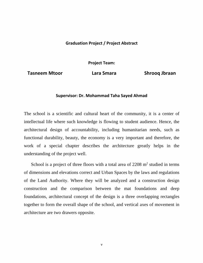
ھي بمثابة القلب العلمي والثقافي للمجتمع ، فھي عبارة عن مركز الحیاة الفكریة حیث تتدفق منھا المدرسة
المعرفة إلى جمھور الطلبة. ومن ھنا فان التصمیم المعماري بما یلبیھ من احتیاجات إنسانیھ مثل الدیمومة
فصل خاص بالوصف المعماري الوظیفیھ , الجمال ,االقتصاد تعتبر في غایة االھمیھ وبالتالي فان عمل
.یساعد بشكل كبیر في فھم المشروع بشكل جید
مدروسة من ناحیة االبعاد واالرتفاعات 2م 2208المشروع عبارة مدرسة من ثالث طوابق بمساحة اجمالیة
والفراغات العمرانیة الصحیحة حسب القوانین واالنظمة المعمول بھا في سلطة االراضي. حیث سیتم تحلیل
الفكرة التصمیمیة المعماریة ،صمیم البناء انشائیا والمقارنة بین األساسات الحصیرة واألساسات العمیقة وت
عبارة عن تداخل لثالث مستطیالت مع بعضھا لتشكل الشكل العام للمدرسة ومحاور الحركة الرأسیة في
العمارة ھي درجین متقابلین .
v
Graduation Project / Project Abstract
Project Team:
Shrooq Jbraan Lara Smara Tasneem Mtoor
Supervisor: Dr. Mohammad Taha Sayed Ahmad
The school is a scientific and cultural heart of the community, it is a center of
intellectual life where such knowledge is flowing to student audience. Hence, the
architectural design of accountability, including humanitarian needs, such as
functional durability, beauty, the economy is a very important and therefore, the
work of a special chapter describes the architecture greatly helps in the
understanding of the project well.
School is a project of three floors with a total area of 2208 m2 studied in terms
of dimensions and elevations correct and Urban Spaces by the laws and regulations
of the Land Authority. Where they will be analyzed and a construction design
construction and the comparison between the mat foundations and deep
foundations, architectural concept of the design is a three overlapping rectangles
together to form the overall shape of the school, and vertical axes of movement in
architecture are two drawers opposite.
vi
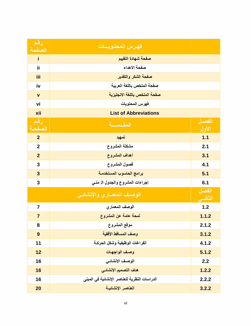
رقـم ةالصفح فھـرس المحتـویـــات
i صفحة شھادة التقییم
ii صفحة االھداء
iii صفحة الشكر والتقدیر
iv صفحة الملخص باللغة العربیة
v صفحة الملخص باللغة االنجلیزیة
vi فھرس المحتویات
xii List of Abbreviations
رقـم ـةالصفح الفصـل المقـدمــــة
األول 1.1 تمھید 2
12. مشكلة المشروع 2
3.1 أھداف المشروع 2
14. فصول المشروع 3
5.1 برامج الحاسوب المستخدمـة 3
والجدول الزمنـي جراءات المشروعإ 3 .16
واإلنشائـي الوصـف المعمـاري الفصل الثانــي
1.2 الوصف المعماري 7
21.1. لمحة عامة عن المشروع 7
2.1.2 موقع المشروع 8
21.3. وصف المساقط األفقیة 9
24.1. الفراغات الوظیفیة وشكل الحركـة 11
25.1. وصـف الواجھـات 12
2.2 الوصـف اإلنشائـي 16
1.2.2 ھدف التصمیم اإلنشائـي 16
2.2.2 الدراسات النظریة للعناصر اإلنشائیة في المبنى 16
3.2.2 العناصر اإلنشائیـة 20
vii
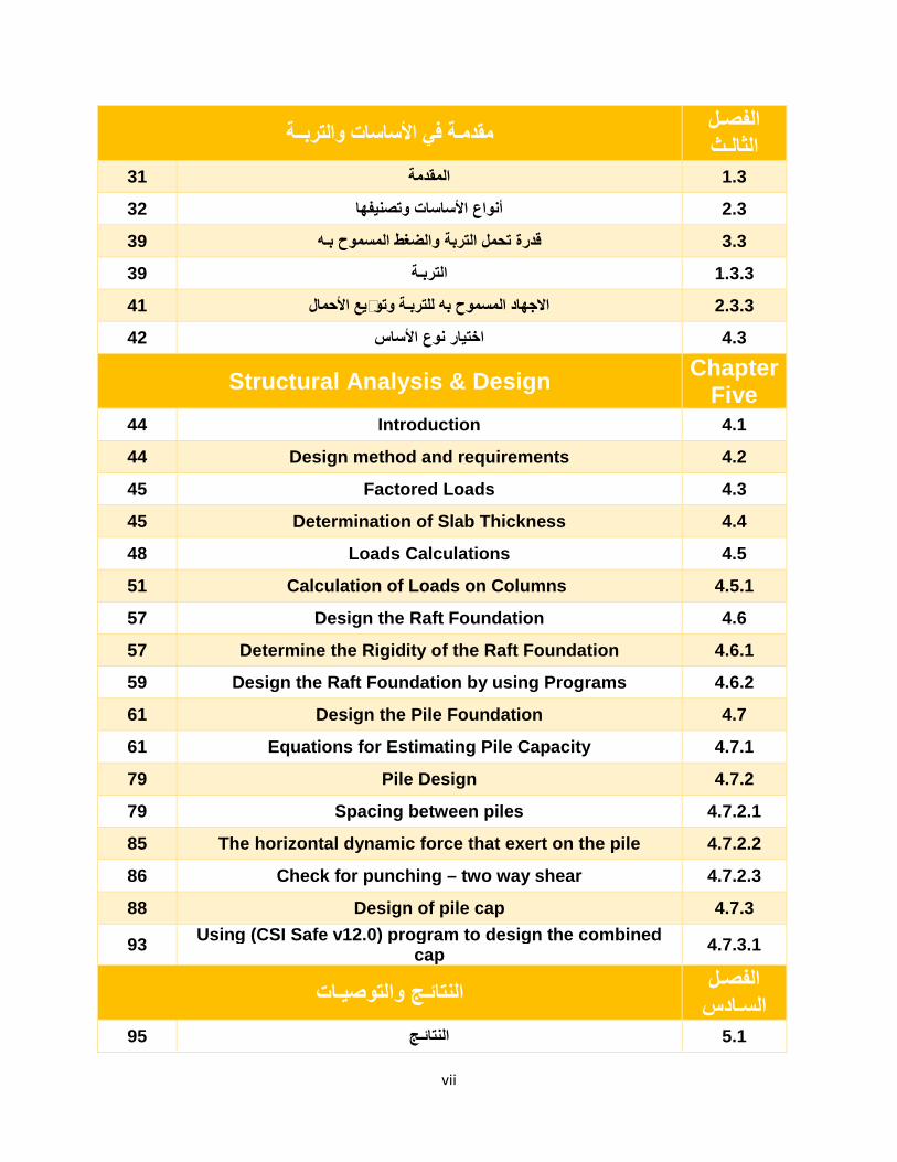
الفصـل مقدمـة في األساسات والتربــة الثالـث
3.1 المقدمة 31
3.2 أنواع األساسات وتصنیفھا 32
3.3 قدرة تحمل التربة والضغط المسموح بـھ 39
3.1.3 التربـة 39
وتوزیع األحمال االجھاد المسموح بھ للتربـة 41 3.2.3
3.4 اختیار نوع األساس 42
Structural Analysis & Design Chapter Five
44 Introduction 4.1
44 Design method and requirements 4.2
45 Factored Loads 4.3
45 Determination of Slab Thickness 4.4
48 Loads Calculations 4.5
51 Calculation of Loads on Columns 4.5.1
57 Design the Raft Foundation 4.6
57 Determine the Rigidity of the Raft Foundation 4.6.1
59 Design the Raft Foundation by using Programs 4.6 .2
61 Design the Pile Foundation 4.7
61 Equations for Estimating Pile Capacity 4.7.1
79 Pile Design 4.7.2
79 Spacing between piles 4.7.2.1
85 The horizontal dynamic force that exert on the pile 4.7.2.2
86 Check for punching – two way shear 4.7.2.3
88 Design of pile cap 4.7.3
93 Using (CSI Safe v12.0) program to design the combined cap 4.7.3.1
الفصـل النتائـج والتوصیـات السـادس
5.1 النتائـج 95
viii
5.2 التوصیـات 96
جـعاالمصادر والمر 97 5.3
رقـم ـةالصفح فھـرس األشكــال
)1-2( الموقع العام للمشروع 7
)2-2( صورة جویة لمنطقة المشروع المقترح "بلدة بیت اوال" 8
)3-2( مخطط الطابق االرضي 9
)4-2( مخطط الطابق االول 10
11 )5-2( مخطط الطابق الثاني
)6-2( صورة تبین آلیة الحركة في المنشأة 12
)7-2( الواجھة الجنوبیة "االمامیة" 13
)8-2( الواجھة الشمالیة "الخلفیة" 13
)9-2( الواجھة الشرقیة 14
51 )01-2( الواجھة الغربیة
)11-2( كیفیة تأثیر الریاح 19
)21-2( نموذج لعقدة مصمتة 21
)31-2( عقدات العصب ذات االتجاه الواحد 22
)41-2( عقدات العصب ذات االتجاھین 22
32 )51-2( نموذج لجسر مسحور
)16-2( احدى أشكال األعمدة 24
)17-2( الـدرج 25
)18-2( جدار قص مسلح 26
28 Raft foundation )2-19(
29 Piles Foundations )2-20(
)1-3( نقل األساس لألحمال الواقعة علیھ الى التربة 31
ix
)2-3( أشكال مختلفة ألساس منفرد 33
43 )3-3( أشكال مختلفة ألساس مشترك
53 )4-3( أشكال مختلفة ألساس مشترك
)5-3( قاعدة كابولیة 35
63 )6-3( نموذج ألساس مستمر
36 Raft Foundation )3-7(
)8-3( أشكال مختلفة من أساس الحصیرة 37
)9-3( نموذج ألساس وتدي 38
14 )10-3( شكل توزیع األحمال على التربة
46 Spans for one way rib slab )4-1(
46 Section for two way slab )4-2(
47 Plan for two way rib slab )4-3(
49 One way rib slab )4-4(
50 Two way rib slab )4-5(
51 Area Method )4-6(
52 Distribution areas of floors for structure )4-7(
58 Mat Foundation )4-8(
60 3D – Mat Foundation )4-9(
60 Plan – Mat Foundation )4-01(
61 Ultimate load-carrying capacity of pile )4-11(
64 Application of a ���� method in layered soil )4-21(
65 Unit frictional resistance for piles in sand )4-31(
68 Variation of K with L/D (Redrawn after Coyle and Ca stello, 1981) )4-41(
69 Variation of the maximum values of ��
∗ with soil friction angle ∅� )4-51(
69 Nature of variation of unit point resistance in a homogenous sand )4-61(
27 layered soil and the pile foundation )4-71(
37 Application of a ���� method in layered soil )4-81(
79 Group piles )4-19(
x
08 Overlap stresses of the piles )4-20(
48 Longitudinal bars in the pile and the clear spacing between them )4-12(
48 Spiral reinforcement in the pile and clear spacing between them )4-22(
58 The Horizontal dynamic force that exert on the pile )4-32(
86 Distribution of piles and dimension of cap )4-42 (
88 Cap and piles foundations )4-25(
89 Design of pile-cap reinforcement by truss theory )4-26(
93 Combined Cap (27-4)
رقم ةالصفحـ فھـرس الجــداول
)2015(- )2014خالل السنة الدراسیة ( الجدول الزمني للمشروع 5 )1-1(
)1-2( الكثافة النوعیة للمواد المستخدمة 17
)2-2( األحمال الحیة 18
)3-2( قیمة أحمال الثلوج حسب االرتفاع عن سطح البحر 20
39 Detailed description of the type of soil layers enc ountered during drilling )3-1(
41 Safe bearing capacity values of the foundation at differ ent levels )3-2(
45 Minimum thickness of Non -prestressed beams or one way slabs unless deflections )4-1(
48 Dead Loads calculations for one way rib slab of structure )4-2(
49 Dead Loads calculations for two way rib slab of str ucture )4-3(
53 Loads on columns for two / one way rib slab of stru cture in KN.m )4-4(
54 Loads on columns for both two way & one way rib sla b of structure in KN.m )4-5(
55 Factored Loads on columns in KN.m )4-6(
56 Factored Loads on columns in KN.m )4-7(
59 Modulus of elasticity for different soils )4-8(
64 Variation of ���� with pile embedment length, L )4-9(
xi
67 Magnitude of K versus with pile type )4-10(
70 Interpolated values of ��∗ based on Meyerhof’s theory )4-11(
71 Conducted lab tests on representative samples obtai ned from the drilled boreholes )4-12(
77 Pile capacity and its properties )4-13(
90 Shape of pile caps for 2 to 6 piles formulae for te nsion by truss theory for arrangement of steel )4-14(
(1-5) المقارنة بین أساس الحصیرة واألساسات العمیقة 95
xii
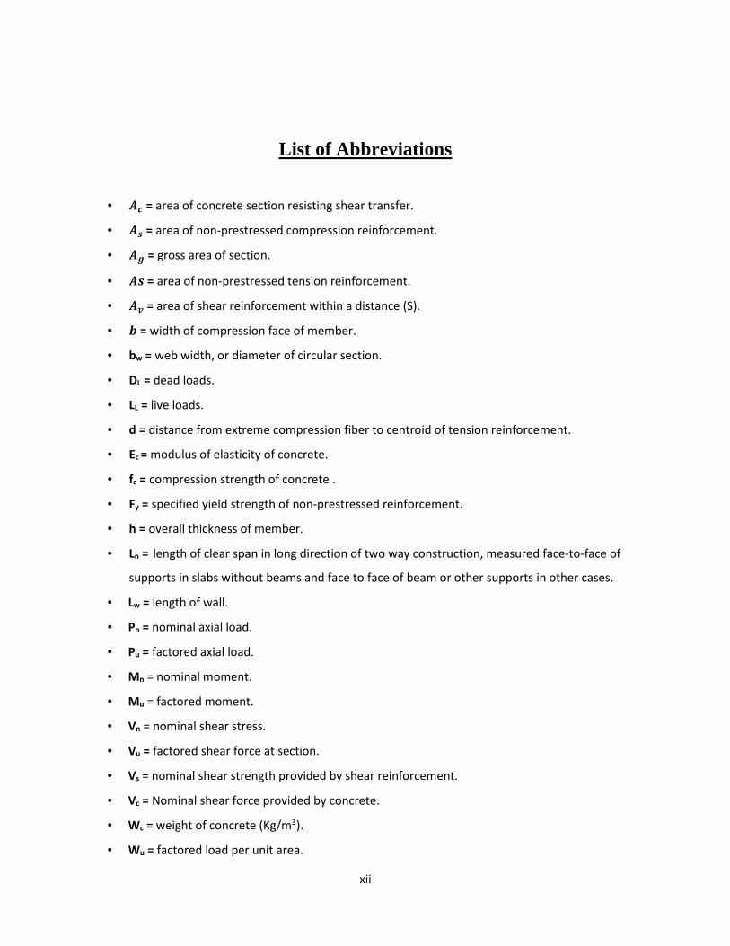
List of Abbreviations
• �� = area of concrete section resisting shear transfer.
• � = area of non-prestressed compression reinforcement.
• � = gross area of section.
• � = area of non-prestressed tension reinforcement.
• �� = area of shear reinforcement within a distance (S).
• � = width of compression face of member.
• bw = web width, or diameter of circular section.
• DL = dead loads.
• LL = live loads.
• d = distance from extreme compression fiber to centroid of tension reinforcement.
• Ec = modulus of elasticity of concrete.
• fc = compression strength of concrete .
• Fy = specified yield strength of non-prestressed reinforcement.
• h = overall thickness of member.
• Ln = length of clear span in long direction of two way construction, measured face-to-face of
supports in slabs without beams and face to face of beam or other supports in other cases.
• Lw = length of wall.
• Pn = nominal axial load.
• Pu = factored axial load.
• Mn = nominal moment.
• Mu = factored moment.
• Vn = nominal shear stress.
• Vu = factored shear force at section.
• Vs = nominal shear strength provided by shear reinforcement.
• Vc = Nominal shear force provided by concrete.
• Wc = weight of concrete (Kg/m³).
• Wu = factored load per unit area.
xiii
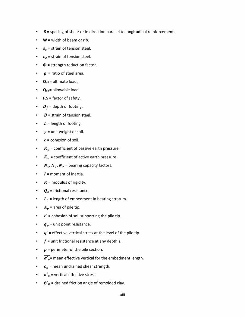
• S = spacing of shear or in direction parallel to longitudinal reinforcement.
• W = width of beam or rib.
• = strain of tension steel.
• � = strain of tension steel.
• Φ = strength reduction factor.
• ρ = ratio of steel area.
• Qull = ultimate load.
• Qall = allowable load.
• F.S = factor of safety.
• �� = depth of footing.
• � = strain of tension steel.
• � = length of footing.
• � = unit weight of soil.
• � = cohesion of soil.
• �� = coefficient of passive earth pressure.
• �� = coefficient of active earth pressure.
• ��, ��, �� = bearing capacity factors.
• � = moment of inertia.
• � = modulus of rigidity.
• � = frictional resistance.
• �� = length of embedment in bearing stratum.
• �� = area of pile tip.
• �′ = cohesion of soil supporting the pile tip.
• �� = unit point resistance.
• �′ = effective vertical stress at the level of the pile tip.
• � = unit frictional resistance at any depth z.
• � = perimeter of the pile section.
• �′�����= mean effective vertical for the embedment length.
• �� = mean undrained shear strength.
• �′� = vertical effective stress.
• ∅′� = drained friction angle of remolded clay.

xiv
• OCR = over consolidation ratio.
• �′ = soil-pile friction angle.
• � = atmospheric pressure.
• �� = unconfined compressive strength.
الفصل األول المقدمة
الفصــــــــــــــل األول الفصــــــــــــــل األول
المقدمـــــــةالمقدمـــــــة
11
تمھید 1.1
مشكلة المشروع 2.1
ھداف المشروعأ 3.1
فصول المشروع 4.1
برامج الحاسوب المستخدمة 5.1
والجدول الزمني جراءات المشروعا 6.1
الفصل األول المقدمة
2
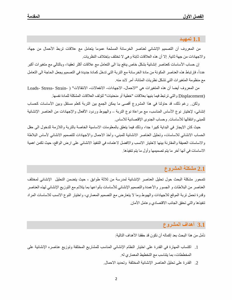
تمھیـد 1.1
من المعروف أن التصمیم اإلنشائي لعناصر الخرسانة المسلحة عموما یتعامل مع عالقات تربط األحمال من جھة،
وھي ال تختلف بإختالف النظریات. ةواالجھادات من جھة ثانیة. إال أن ھذه العالقات ثابت
عالقات أكثر تعقیدا، وبالتالي مع متغیرات أكبر إن حساب األساسات كعناصر إنشائیة بشكل خاص یدفع بنا الى التعامل مع
عددا، فإرتباط ھذه العناصر المكونة من مادة الخرسانة مع التربة التي تدخل كمادة جدیدة في التصمیم یجعل الحاجة الى التعامل
مع منظومة المتغیرات التي تشكل نظریات المتانة، أمر البد منھ.
-Loads- Stress- Strainاالنتقاالت" ( - االنفعاالت -االجھادات -من المعروف أیضا أن ھذه المتغیرات ھي "االحمال
Displacement) .والتي ترتبط فیما بنیھا بعالقات "خطیة أو منحنیات" لتؤلف العالقات المشكلة للمادة نفسھا
لجمع بین التربة كعلم مستقل وبین األساسات كحساب اأقصى ما یمكن المشروع قد حاولنا في ھذاولكن.. رغم ذلك،
اصر اإلنشائیة وردود األفعال واإلجھادات من العن والھبوط –إنشائي، إلختیار نوع األساس المناسب، مع مراعاة نوع التربة
للمبنى وانتقالھا لألساسات. وحساب الجدوى اإلقتصادیة لالساس.
االیجاز في البدایة كبیرا جدا، وذلك فیما یتعلق بالمعلومات االساسیة الخاصة بالتربة والالزمة للدخول الى حقل حیث كان
البالطة ألساس خذ االحمال واالجھادات للتصمیم االنشائيأالحساب االنشائي لالساسات، وتحلیل العناصر االنشائیة للمبنى، و
ختیار االنسب واالفضل العتماده في التنفیذ االنشائي على ارض الواقع، حیث تكمن اھمیة واالساسات العمیقة والمقارنة بینھا ال
االساسات في أنھا أخر ما یتم تصمیمھا وأول ما یتم تنفیذھا.
مشكلة المشروع 2.1
مختلف لاإلنشائي تحلیل، حیث یتضمن اللمدرسة من ثالثة طوابق العناصر اإلنشائیة تحلیلحول تتمحور مشكلة البحث
مع التوزیع اإلنشائي لھذه العناصر مئیتالبما لألساسات بأنواعھا التصمیم اإلنشائيو ةالعناصر من البالطات و الجسور واألعمد
، واختیار النوع االنسب لالساسات المراد وما ال یتعارض مع التصمیم المعماري تربة الموقع لالجھادات والھبوطوقدرة تحمل
الجانب االقتصادي وعامل األمان. تنفیذھا والتي تحقق
المشروعأھداف 3.1
األھداف التالیة: حققنانأمل من ھذا البحث بعد إكمالھ أن نكون قد
القدرة على اختیار النظام اإلنشائي المناسب للمشاریع المختلفة وتوزیع عناصره اإلنشائیة على اكتساب المھارة في .1
المعماري لھ.المخططات، بما یتناسب مع التخطیط
.وتحدید االحمال المختلفةالعناصر اإلنشائیة تحلیلالقدرة على .2
الفصل األول المقدمة
3
.تطبیق وربط المعلومات التي تم دراستھا في المساقات المختلفة .3
استخدام برامج التصمیم اإلنشائي. إتقان .4
امكانیة الجمع بین التربة كعلم مستقل واألساسات كحساب إنشائي. .5
فصول المشروع 4.1
.المقدمة .1
.الوصف المعماري واالنشائي .2
.مقدمة عن االساسات والتربة .3
). Structural Analysis & Designالتحلیل االنشائي والتصمیم ( .4
النتائـج والتوصیـات. .5
برامج الحاسوب المستخدمة 5.1
ھناك عدة برامج تم استخدامھا في المشروع وھي :
1 - AUTOCAD 2013/2007 المفصلة للعناصر اإلنشائیة.: و ذلك لعمل الرسومات
2 - ATIR.للتصمیم والتحلیل اإلنشائي للعناصر اإلنشائیة :
3 - Safe: لتصمیم اساس البالطة /الحصیرة)Mat foundation ولتصمیم الـــ (Combined Cap.
4 - )Office XP( نص المشروع: تم استخدامھ في أجزاء مختلفة من المشروع مثل الكتابة النصوص والتنسیق وإخراج .
والجدول الزمني المشروعإجراءات 6.1
و إختیار المشروع من النواحي المعماریة وتوافقھا مع أھداف لفھمھاالمخططات المعماریة وذلك وتعدیل دراسة -1
النظام اإلنشائي المالئم.
والجسورواألعصاب بشكل ال ألنسب لتوزیع ھذه العناصر كاألعمدةلیة اواآل للمبنىدراسة العناصر اإلنشائیة المكونة -2
.یصطدم مع التصمیم المعماري الموضوع ویحقق الجانب االقتصادي و عامل األمان
وتحلیل العناصر اإلنشائیة على ھذه األحمال . مال المؤثرة على المبنىحتحدید األ -3
دراسة تربة الموقع كعلم مستقل وتحدید نوعیة التربة وقدرة تحملھا. -4
المنفردة، واساسات البالطة، واالساسات العمیقة .الساسات الوصول الى مخطط األساسات والتصمیم اإلنشائي ل -5

الفصل األول المقدمة
4
المقارنة بین انواع االساسات واختیار األنسب من حیث قدرة التحمل والجدوى اإلقتصادیة ومدى مالئمتھا لتربة -6
الموقع.
والقابل النھائي المتكامل ھئیة التي تم تصمیمھا لیخرج المشروع بشكلإنجاز المخططات التنفیذیة للعناصر اإلنشا -7
للتنفیذ.
والجدول التالي یوضح تسلسل أعمال المشروع والزمن الالزم لكل نشاط.
الفصل األول المقدمة
5
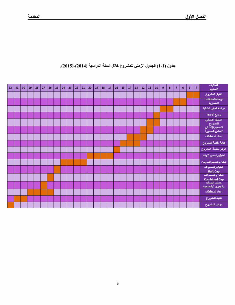
.)2015(- )2014) الجدول الزمني للمشروع خالل السنة الدراسیة (1-1جدول (
الفصل الثاني الوصف المعماري واالنشائي
الفصــــــــل الثانـــــــــــــــــي الفصــــــــل الثانـــــــــــــــــي
نشائينشائيواإلواإل الوصف المعمـــــــــــاريالوصف المعمـــــــــــاري
22
الوصف المعماري 1.2
لمحة عن المشروع 1.1.2
موقع المشروع 2.1.2
وصف المساقط األفقیة 3.1.2
وشكل الحركةلفراغات الوظیفیة ا 4.1.2
وصف الواجھات 5.1.2
الوصف االنشائي 2.2
ھدف التصمیم اإلنشائي 1.2.2
الدراسات النظریة للعناصر اإلنشائیة في المبنى 2.2.2
العناصر اإلنشائیة 3.2.2
الفصل الثاني الوصف المعماري واالنشائي
7
عن المشروععامـة لمحة 1.1.2
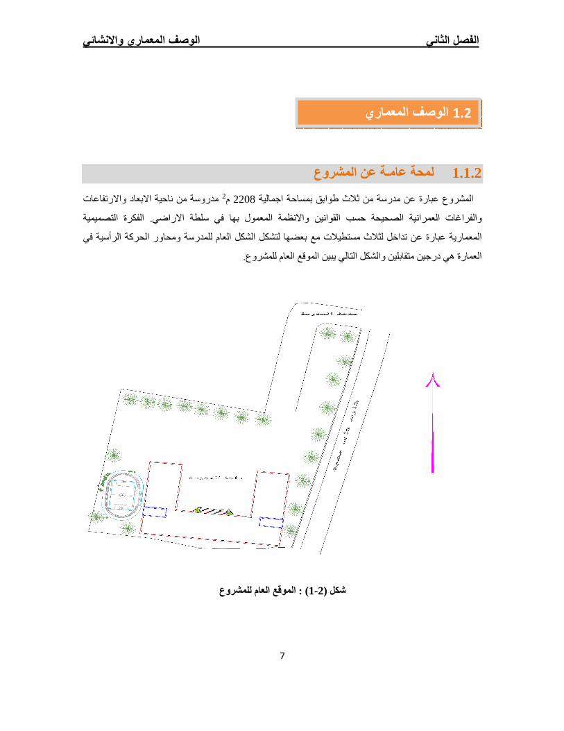
مدروسة من ناحیة االبعاد واالرتفاعات 2م 2208بمساحة اجمالیة مدرسة من ثالث طوابق عن المشروع عبارة
الفكرة التصمیمیة ظمة المعمول بھا في سلطة االراضي. سب القوانین واالنحوالفراغات العمرانیة الصحیحة
ة في ومحاور الحركة الرأسیالمعماریة عبارة عن تداخل لثالث مستطیالت مع بعضھا لتشكل الشكل العام للمدرسة
ن والشكل التالي یبین الموقع العام للمشروع. العمارة ھي درجین متقابلی
عام للمشروعالموقع ال : )1- 2( شكل
الوصف المعماري 1.2
الفصل الثاني الوصف المعماري واالنشائي
8
موقع المشروع 2.1.2
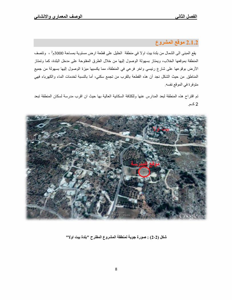
وتتصف ، 2م3000على قطعة ارض مستویة بمساحة الخلیل یقع المبنى الى الشمال من بلدة بیت اوال في منطقة
تمتاز ، كما والبلدةمن خالل الطرق المفتوحة على مدخل االوصول إلیھ بسھولةمتاز یوبموقعھا الخالب، المنطقة
بسھولة من جمیع امیزة الوصول إلیھا في المنطقة، مما یكسبھ واخر فرعي بوقوعھا على شارع رئیسياألرض
خدمات الماء والكھرباء فھي لبالنسبة أما ،ھذه القطعة بالقرب من تجمع سكني أن نجد شكلحیث الالمناطق. من
.الموقع نفسھ متوفرة في
اقرب مدرسة لسكان المنطقة تبعد تم اقتراح ھذه المنطقة لبعد المدارس عنھا وللكثافة السكانیة العالیة بھا حیث ان
كــم. 2
"بلدة بیت اوالصورة جویة لمنطقة المشروع المقترح " : )2- 2( شكل
الفصل الثاني الوصف المعماري واالنشائي
9
وصف المساقط األفقیة 3.1.2
االرضي طابق ال .1
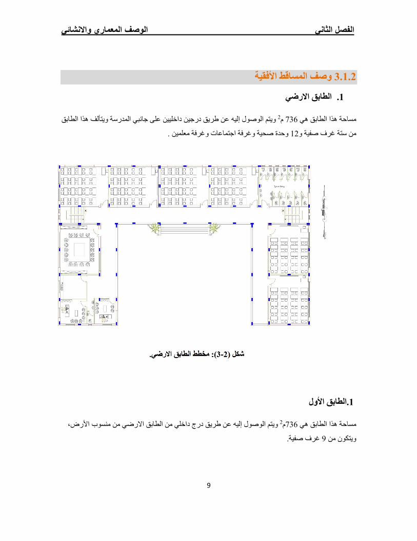
على جانبي المدرسة ویتألف ھذا الطابق داخلیین درجین عن طریق إلیھیتم الوصول و 2م 736ھي مساحة ھذا الطابق
وحدة صحیة وغرفة اجتماعات وغرفة معلمین . 12من ستة غرف صفیة و
.ضيرالطابق اال): مخطط 3- 2شكل (
.الطابق األول1
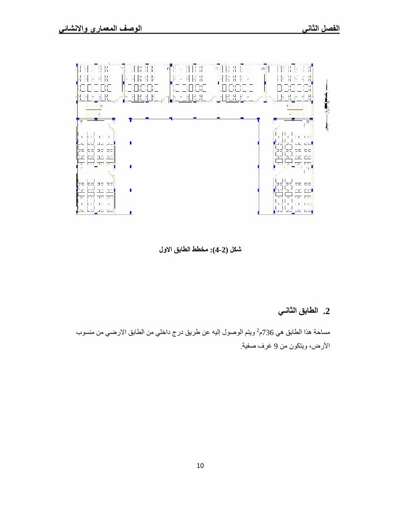
درج داخلي من الطابق االرضي من منسوب األرض، عن طریق إلیھیتم الوصول و 2م736مساحة ھذا الطابق ھي
.صفیةغرف 9من ویتكون
الفصل الثاني الوصف المعماري واالنشائي
10
االول الطابق ): مخطط 4- 2( شكل
يـلثاناالطابق .2
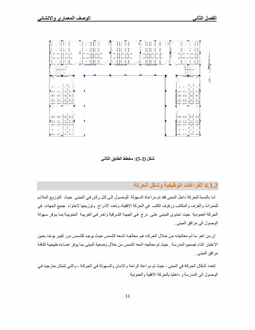
سوب درج داخلي من الطابق االرضي من من عن طریق إلیھیتم الوصول و 2م736مساحة ھذا الطابق ھي
غرف صفیة. 9من ویتكون األرض،
الفصل الثاني الوصف المعماري واالنشائي
11
الطابق الثاني ): مخطط 5- 2( شكل
شكل الحركةوالفراغات الوظیفیة 4.1.2
بالنسبة للحركة داخل المبنى فقد تم مراع`اة الس`ھولة للوص`ول ال`ى ك`ل رك`ن ف`ي المبن`ى حی`ث التوزی`ع المالئ`م امأ
وتوزیعھا الحتواء جمیع الجھات في للممرات والغرف والمكاتب ورفوف الكتب في الحركة االفقیة، وتعدد االدراج
بم`ا ی`وفر س`ھولة الجنوبی`ة واخ`ر ف`ي الغربی`ة ف`ي الجھ`ة الش`رقیة الحركة العمودیة حیت احت`وى المبن`ى عل`ى درج
.الوصول الى مرافق المبنى
للش`مس دور كبی`ر یؤخ`د بع`ین یوج`دمن اھم ما ت`م معالجت`ھ م`ن خ`الل الحرك`ھ ھ`و معالج`ھ اش`عھ الش`مس حی`ث ان
بما یوفر اض`اءة طبیعی`ة لكاف`ة من خالل وضعیة المبنى. حیث تم معالجھ اشعھ الشمس المدرسةاالعتبار اثناء تصمیم
مرافق المبنى .
والس`ھولة ف`ي الحرك`ة ، والت`ي تتمث`ل خارجی`ا ف`ي الراحة واالم,انالحركة في المبنى ، حیث تم مراعاة أشكالتتعدد
و داخلیا بالحركة االفقیة والعمودیة . المدرسةل الى الوصو
الفصل الثاني الوصف المعماري واالنشائي
12
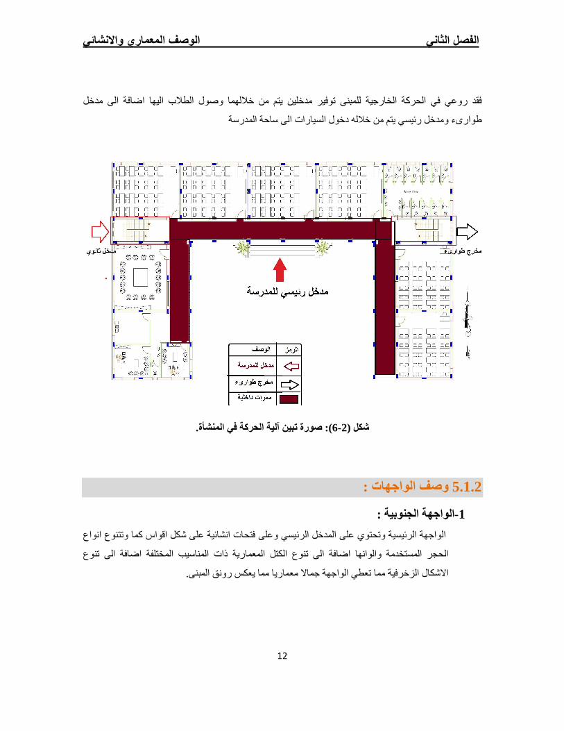
وصول الطالب الیھا اضافة الى مدخل فقد روعي في الحركة الخارجیة للمبنى توفیر مدخلین یتم من خاللھما
طوارىء ومدخل رئیسي یتم من خاللھ دخول السیارات الى ساحة المدرسة
المنشأة.تبین آلیة الحركة في صورة ):6- 2( شكل
وصف الواجھات : 5.1.2
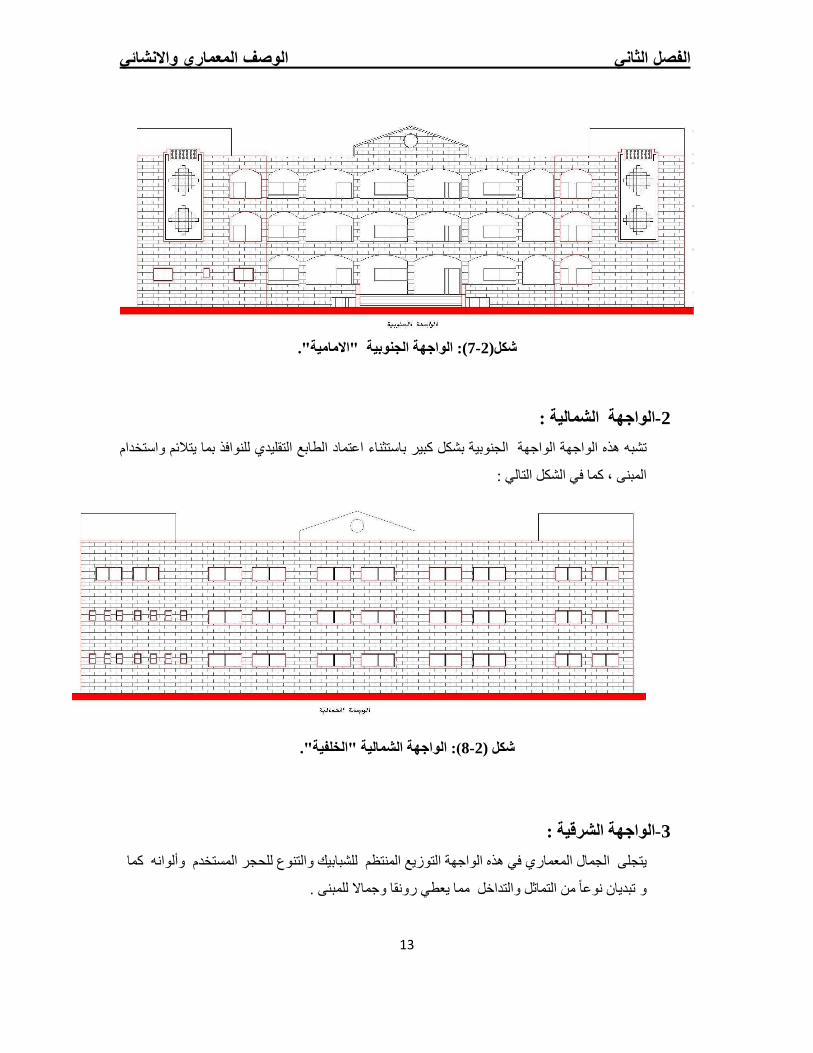
:الجنوبیة لواجھةا-1
كما وتتنوع انواع اقواس فتحات انشائیة على شكل وتحتوي على المدخل الرئیسي وعلى الواجھة الرئیسیة
ا اضافة الى تنوع الكتل المعماریة ذات المناسیب المختلفة اضافة الى تنوع الحجر المستخدمة والوانھ
.یعكس رونق المبنىمما مما تعطي الواجھة جماال معماریا االشكال الزخرفیة
الفصل الثاني الوصف المعماري واالنشائي
13
"االمامیة". الواجھة الجنوبیة :)7- 2شكل(
: الشمالیة الواجھة-2
باستثناء اعتماد الطابع التقلیدي للنوافذ بما یتالئم واستخدام بشكل كبیر الجنوبیة الواجھة ھذه الواجھة تشبھ
: كما في الشكل التالي ،المبنى
."الخلفیة" الشمالیة): الواجھة 8- 2( شكل
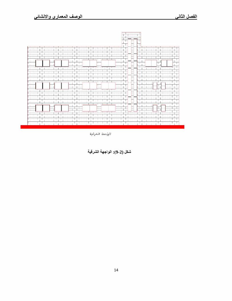
: الواجھة الشرقیة-3
التنوع للحجر المستخدم وألوانھ كما والتوزیع المنتظم للشبابیك اجھةجلى الجمال المعماري في ھذه الویت
. مما یعطي رونقا وجماال للمبنى نوعا من التماثل والتداخل و تبدیان
الفصل الثاني الوصف المعماري واالنشائي
14
الشرقیة): الواجھة 9- 2( شكل
الفصل الثاني الوصف المعماري واالنشائي
15
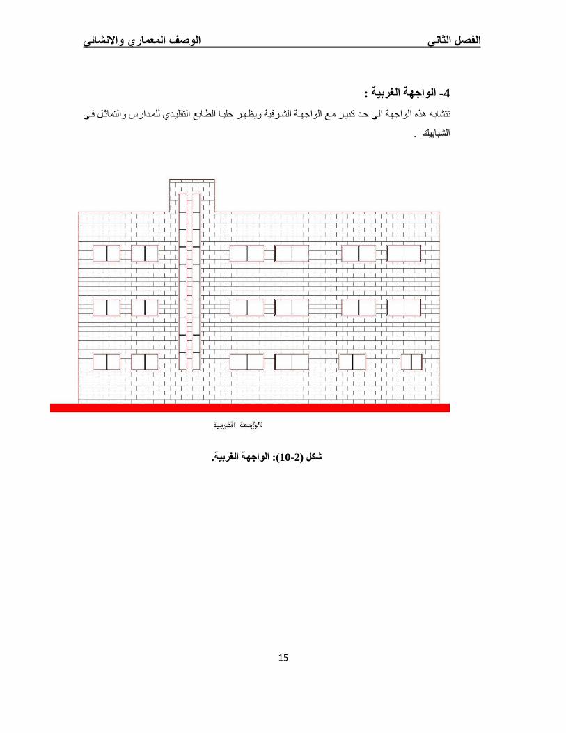
: الغربیةالواجھة -4
ف`ي ویظھ`ر جلی`ا الط`ابع التقلی`دي للم`دارس والتماث`ل تتشابھ ھذه الواجھة الى ح`د كبی`ر م`ع الواجھ`ة الش`رقیة
. الشبابیك
.الغربیة): الواجھة 10- 2( شكل
الفصل الثاني الوصف المعماري واالنشائي
16
ھدف التصمیم اإلنشائـي 1.2.2
م`ن جمی`ع الن`واحي الھندس`یة اإلنش`ائیة ومق`اوم ومت,زن مت`ینإنت`اج منش`أ إل`ىیھدف التصمیم اإلنشائي بشكل أساس`ي
ثل`وج. وبالت`الي ی`تم وال ی`احوالر زالزلأحمال میتة وحیة وأیضا أحمال بیئیة من تأثیر ال`لجمیع المؤثرات الخارجیة من
تحدید العناصر اإلنشائیة بناء على:
: یتم تحقیقھ عبر اختیار مقاطع للعناصر اإلنشائیة قادرة على تحمل القوى و اإلجھادات ) ( Safetyاألمان •
الناتجة عنھا.
مواد البناء ومقاطع مناسبة التكلفة و كافیة للغرض الذي ستستخدم من : یتم تحقیقھا عن طریق)(Costالتكلفة •
أجلھ.
و تجنب ) settlementد ( من حیث تجنب أي ھبوط زائ (Serviceability)حدود صالحیة المبنى للتشغیل •
التي تؤثر سلبا على المنظر المعماري المطلوب. (Cracks)التشققات
الشكل و النواحي الجمالیة للمنشأ. •
للعناصر اإلنشائیة في المبنىالدراسات النظریة 2.2.2
حیث أنھ من خاللھا یمكن والتصمیمتعتبر الدراسة النظریة جزء رئیسي ومھم یجب القیام بھ إلتمام عملیة التحلیل
لذلك یجب دراسة العناصر اإلنشائیة بشكل جید وتحدید األحمال التحلیلعملیات یكون منالوصول إلى أفضل ما
الواقعة على كل عنصر للوصول إلى التصمیم المتین واآلمن وطریقة العمل المناسبة.
األحمال 1.2.2.2
انھیارحدوث نقادرة على تحمل األحمال الواقعة علیھا دو تصمیمھا أن تكونالبد للعناصر اإلنشائیة التي یتم
للمنشاة ومن ھذه األحمال: األحمال المیتة، األحمال الحیة، واألحمال البیئیة.
الوصف االنشائي 2.2
الفصل الثاني الوصف المعماري واالنشائي
17
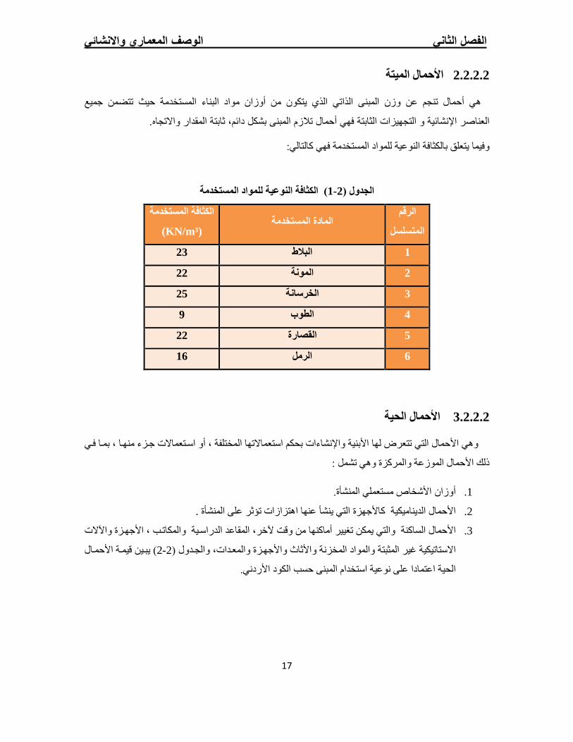
األحمال المیتة 2.2.2.2
ھي أحمال تنجم عن وزن المبنى الذاتي الذي یتكون من أوزان مواد البناء المستخدمة حیث تتضمن جمیع
بشكل دائم، ثابتة المقدار واالتجاه.العناصر اإلنشائیة و التجھیزات الثابتة فھي أحمال تالزم المبنى
وفیما یتعلق بالكثافة النوعیة للمواد المستخدمة فھي كالتالي:
) الكثافة النوعیة للمواد المستخدمة1- 2جدول (ال
الرقم
المتسلسل المادة المستخدمة
الكثافة المستخدمة
)KN/m³(
23 البالط 1
22 المونة 2
25 الخرسانة 3
9 الطوب 4
22 القصارة 5
16 الرمل 6
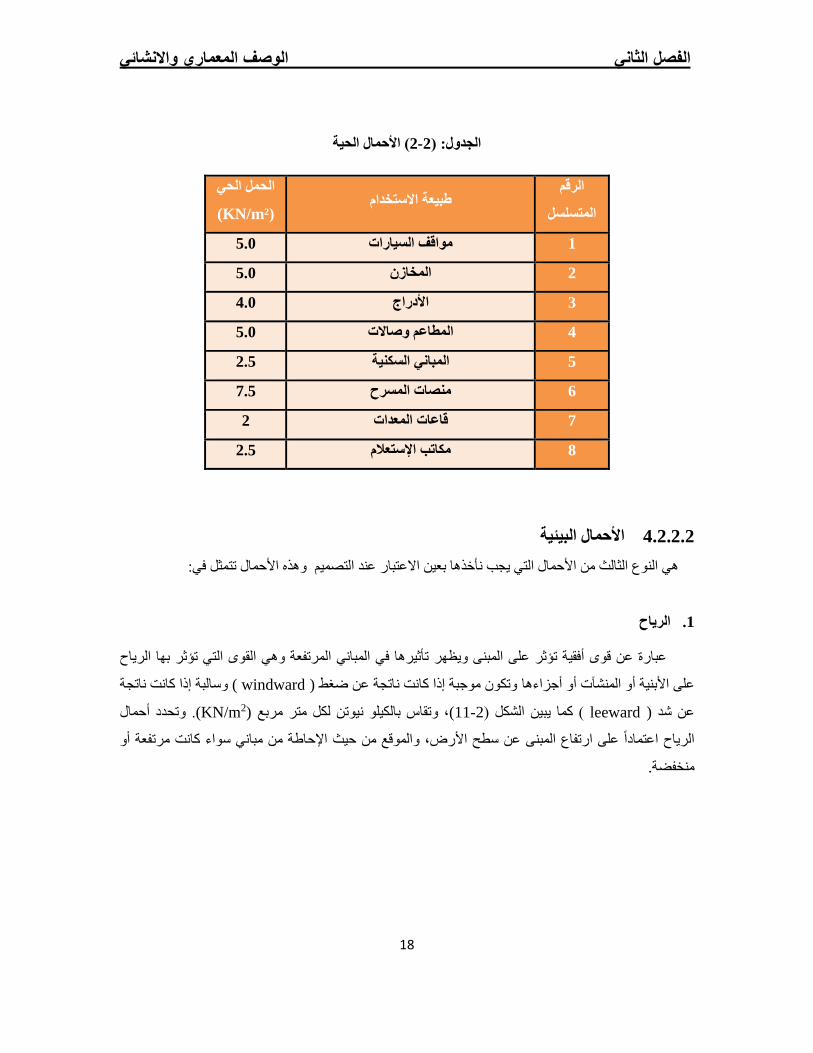
األحمال الحیة 3.2.2.2
بم`ا ف`ي ،اس`تعماالت ج`زء منھ`ا أو ،وھي األحمال التي تتعرض لھا األبنیة واإلنشاءات بحكم استعماالتھا المختلفة
وھي تشمل : ذلك األحمال الموزعة والمركزة
ة.األشخاص مستعملي المنشأأوزان .1
. ةعنھا اھتزازات تؤثر على المنشأ أكاألجھزة التي ینش األحمال الدینامیكیة .2
األجھ`زة واآلالت ، الدراس`یة والمكات`بالمقاعد ،والتي یمكن تغییر أماكنھا من وقت آلخر األحمال الساكنة .3
) یب`ین قیم`ة األحم`ال 2-2الج`دول (األثاث واألجھ`زة والمع`دات، وو والمواد المخزنة االستاتیكیة غیر المثبتة
الحیة اعتمادا على نوعیة استخدام المبنى حسب الكود األردني.
الفصل الثاني الوصف المعماري واالنشائي
18
) األحمال الحیة2-2الجدول: (
الرقم
المتسلسل طبیعة االستخدام
الحمل الحي
)KN/m²(
5.0 مواقف السیارات 1
5.0 المخازن 2
4.0 األدراج 3
5.0 وصاالت المطاعم 4
2.5 المباني السكنیة 5
7.5 منصات المسرح 6
2 قاعات المعدات 7
2.5 مكاتب اإلستعالم 8
األحمال البیئیة 4.2.2.2
وھذه األحمال تتمثل في: أخذھا بعین االعتبار عند التصمیمنثالث من األحمال التي یجب النوع الي ھ
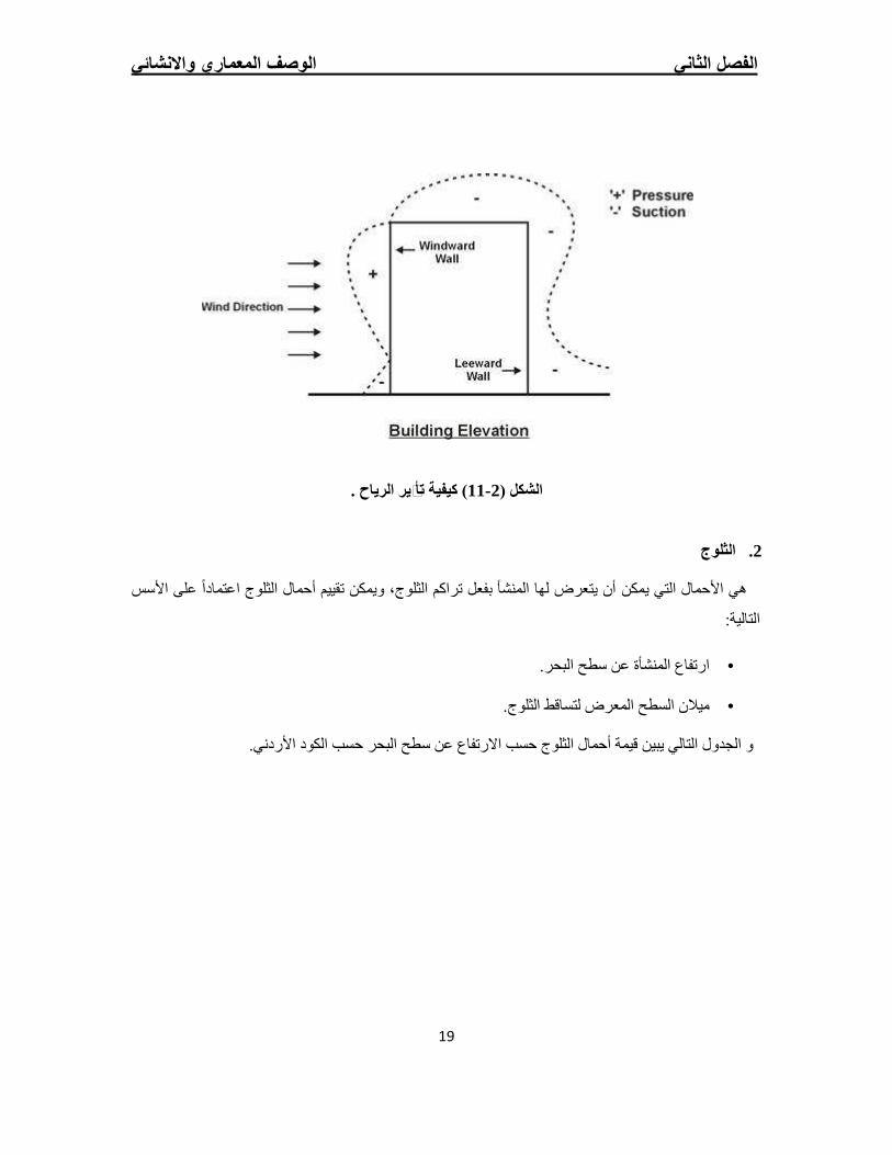
الریاح .1
وھي القوى التي تؤثر بھا الریاح لمرتفعة تؤثر على المبنى ویظھر تأثیرھا في المباني ا أفقیةعبارة عن قوى
وسالبة إذا كانت ناتجة ) windward( ة عن ضغط موجبة إذا كانت ناتج أجزاءھا وتكونعلى األبنیة أو المنشآت أو
. وتحدد أحمال )2KN/m( لكل متر مربع ، وتقاس بالكیلو نیوتن)11- 2) كما یبین الشكل ( leeward( عن شد
الریاح اعتمادا على ارتفاع المبنى عن سطح األرض، والموقع من حیث اإلحاطة من مباني سواء كانت مرتفعة أو
منخفضة.
الفصل الثاني الوصف المعماري واالنشائي
19
ر الریاح .ی) كیفیة تأث11- 2الشكل (
الثلوج .2
یتعرض لھا المنشأ بفعل تراكم الثلوج، ویمكن تقییم أحمال الثلوج اعتمادا على األسس یمكن أنھي األحمال التي
التالیة:
عن سطح البحر. ةارتفاع المنشأ •
السطح المعرض لتساقط الثلوج. میالن •
الثلوج حسب االرتفاع عن سطح البحر حسب الكود األردني. و الجدول التالي یبین قیمة أحمال
الفصل الثاني الوصف المعماري واالنشائي
20
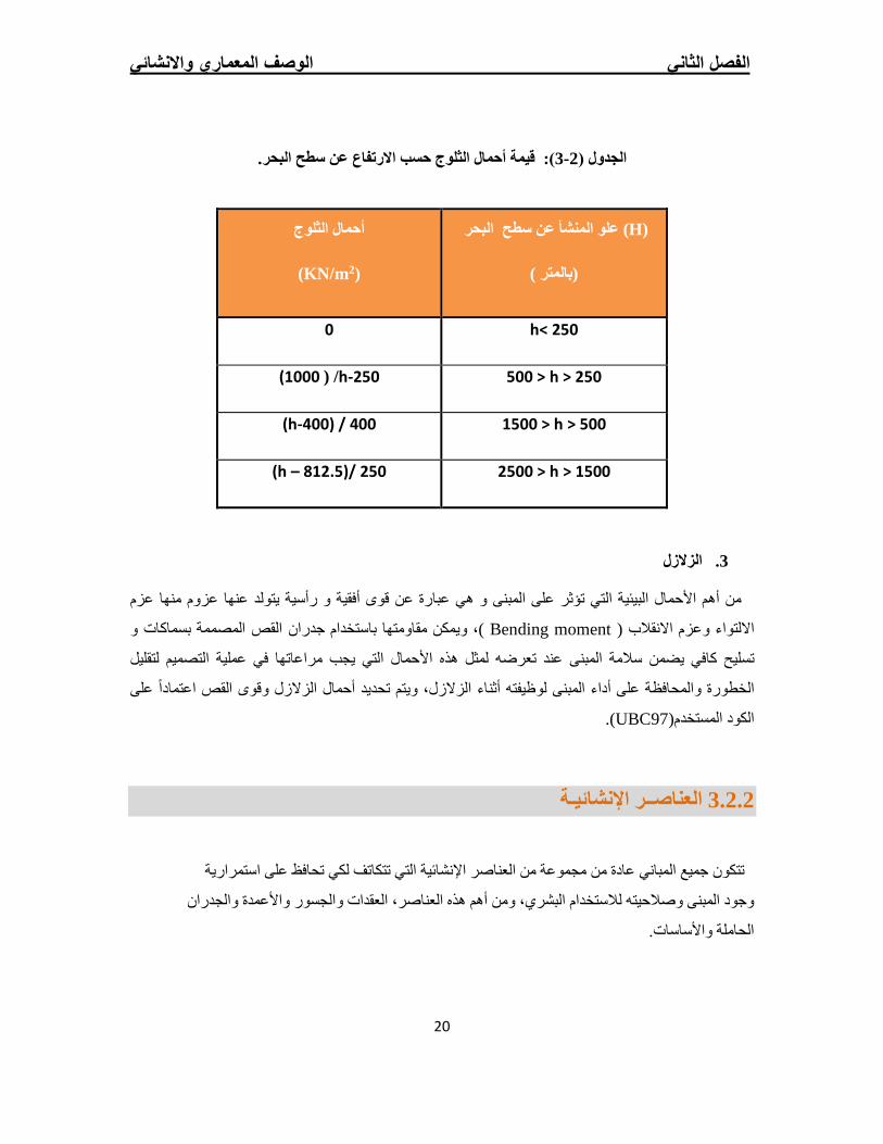
حر.): قیمة أحمال الثلوج حسب االرتفاع عن سطح الب3- 2الجدول (
(H) البحر علو المنشأ عن سطح
(بالمتر )
أحمال الثلوج
(KN/m2)
h< 250 0
500 > h > 250 (1000 ) /h-250
1500 > h > 500 (h-400) / 400
2500 > h > 1500 (h – 812.5)/ 250
الزالزل .3
یتولد عنھا عزوم منھا عزم و رأسیة من أھم األحمال البیئیة التي تؤثر على المبنى و ھي عبارة عن قوى أفقیة
بسماكات و المصممة جدران القصویمكن مقاومتھا باستخدام ،) Bending moment( االنقالبوعزم االلتواء
یجب مراعاتھا في عملیة التصمیم لتقلیل التيتسلیح كافي یضمن سالمة المبنى عند تعرضھ لمثل ھذه األحمال
على الخطورة والمحافظة على أداء المبنى لوظیفتھ أثناء الزالزل، ویتم تحدید أحمال الزالزل وقوى القص اعتمادا
.)UBC97(الكود المستخدم
ناصــر اإلنشائیـةالع 3.2.2
تمراریة جمیع المباني عادة من مجموعة من العناصر اإلنشائیة التي تتكاتف لكي تحافظ على اس تتكون
ران والجدوجود المبنى وصالحیتھ لالستخدام البشري، ومن أھم ھذه العناصر، العقدات والجسور واألعمدة
الحاملة واألساسات.
الفصل الثاني الوصف المعماري واالنشائي
21
العقدات 2.2.3.1
ناصر ھي عبارة عن العناصر اإلنشائیة القادرة على نقل القوى الرأسیة بسبب األحمال المؤثرة علیھا إلى الع
الجسور والجدران واألعمدة، دون تعرضھا إلى تشوھات.اإلنشائیة الحاملة في المبنى مثل
ما یلي : الخرسانیة المسلحة ، منھا العقداتتوجد أنواع مختلفة وعدیدة شائعة االستعمال من
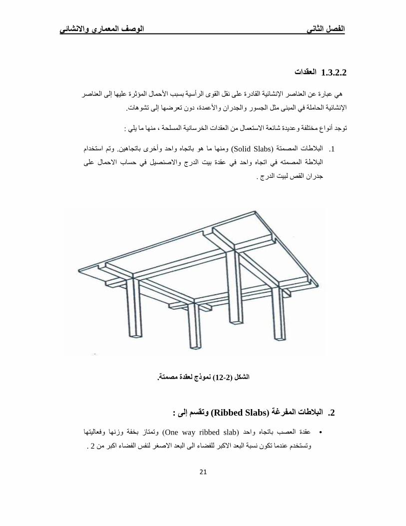
وتم استخدام .باتجاھین ومنھا ما ھو باتجاه واحد وأخرى )Solid Slabsالبالطات المصمتة ( .1
واالصنصیل في حساب االحمال على بیت الدرج ةعقدالبالطة المصمتھ في اتجاه واحد في
لبیت الدرج . جدران القص
.ة) نموذج لعقدة مصمت12- 2الشكل (
وتقسم إلى : )Ribbed Slabsالبالطات المفرغة ( .2
) وتمتاز بخفة وزنھا وفعالیتھا One way ribbed slabعقدة العصب باتجاه واحد ( •
. 2نسبة البعد االكبر للفضاء الى البعد االصغر لنفس الفضاء اكبر من تكونوتستخدم عندما
الفصل الثاني الوصف المعماري واالنشائي
22
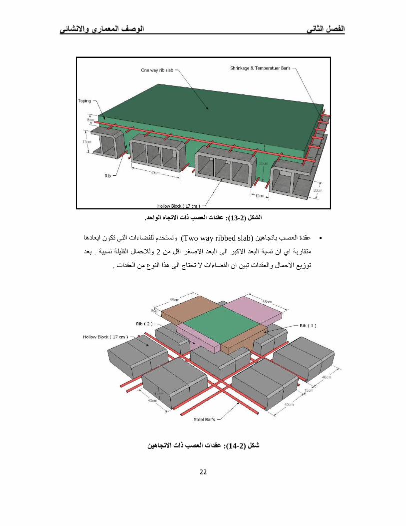
عقدات العصب ذات االتجاه الواحد. ):13- 2الشكل (
ابعادھا نوتستخدم للفضاءات التي تكو )Two way ribbed slab( باتجاھینعقدة العصب •
ولالحمال القلیلة نسبیة . بعد 2نسبة البعد االكبر الى البعد االصغر اقل من انمتقاربة اي
. الفضاءات ال تحتاج الى ھذا النوع من العقدات ان توزیع االحمال والعقدات تبین
ذات االتجاھین): عقدات العصب 14- 2شكل (
الفصل الثاني الوصف المعماري واالنشائي
23
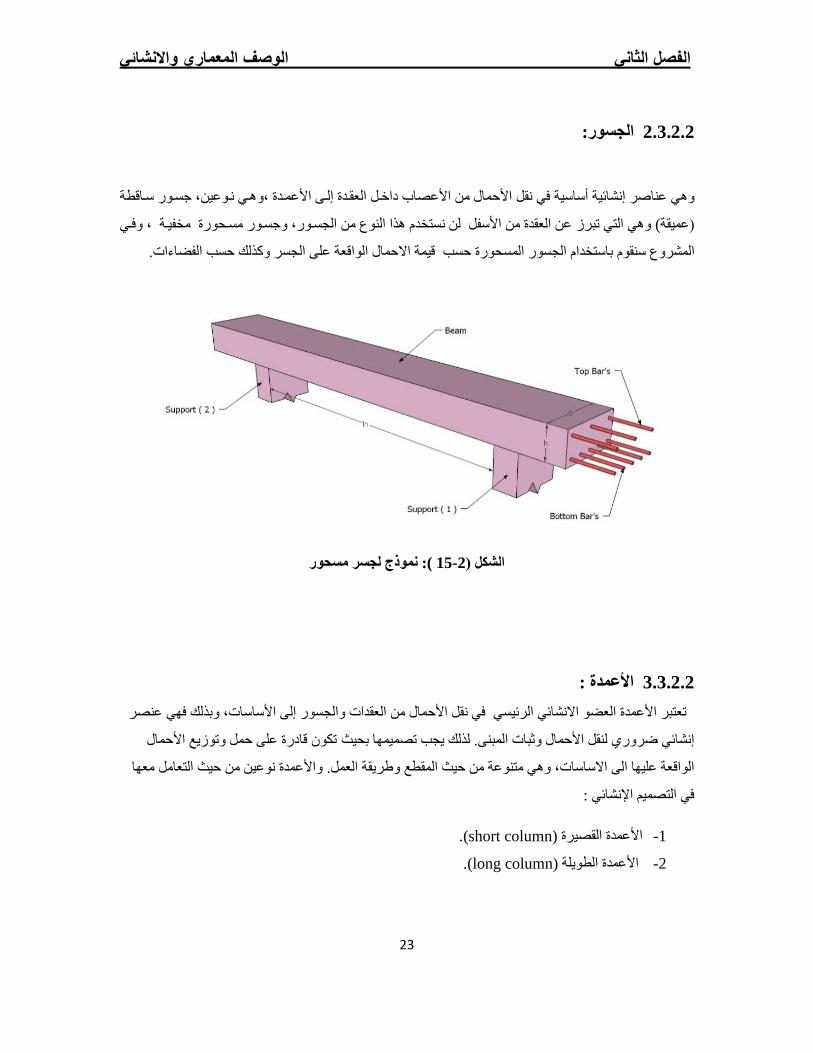
الجسور: 2.3.2.2
س`اقطة ، جس`ورل العق`دة إل`ى األعم`دة ،وھ`ي ن`وعینوھي عناصر إنشائیة أساسیة في نقل األحمال من األعصاب داخ`
وف`ي جس`ور مس`حورة مخفی`ة ، لن نستخدم ھذا النوع من الجس`ور، و وھي التي تبرز عن العقدة من األسفل) (عمیقة
حمال الواقعة على الجسر وكذلك حسب الفضاءات. حسب قیمة اال ةالجسور المسحور باستخدامالمشروع سنقوم
نموذج لجسر مسحور :) 15- 2الشكل (
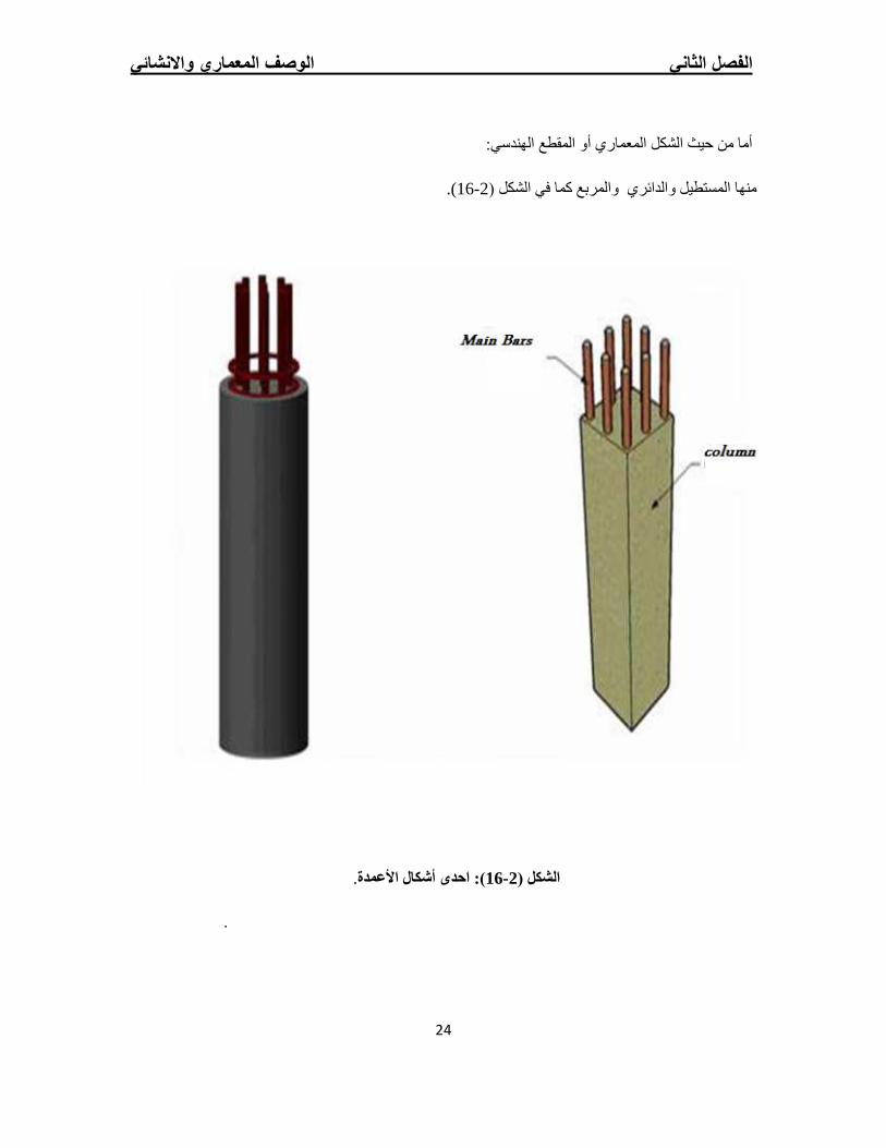
: األعمدة 2.2.3.3
فھي عنصر في نقل األحمال من العقدات والجسور إلى األساسات، وبذلك العضو االنشائي الرئیسي تعتبر األعمدة
األحمال قادرة على حمل وتوزیع تكون إنشائي ضروري لنقل األحمال وثبات المبنى. لذلك یجب تصمیمھا بحیث
عھا م واألعمدة نوعین من حیث التعامل الى االساسات، وھي متنوعة من حیث المقطع وطریقة العمل. الواقعة علیھا
: في التصمیم اإلنشائي
).(short columnاألعمدة القصیرة -1
).(long columnاألعمدة الطویلة -2
الفصل الثاني الوصف المعماري واالنشائي
24
أما من حیث الشكل المعماري أو المقطع الھندسي:
).16- 2كما في الشكل (والمربع منھا المستطیل والدائري
.): احدى أشكال األعمدة61- 2الشكل (
.
الفصل الثاني الوصف المعماري واالنشائي
25
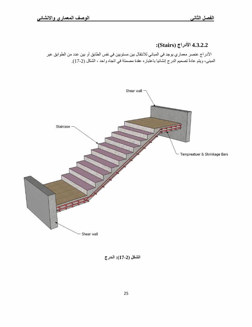
):Stairsاألدراج ( 4.3.2.2
الطوابق عبر األدراج عنصر معماري یوجد في المباني لالنتقال بین مستویین في نفس الطابق أو بین عدد من ).71-2الشكل ( ، واحدالمبنى، ویتم عادة تصمیم الدرج إنشائیا باعتباره عقدة مصمتة في اتجاه
): الـدرج17- 2الشكل (
الفصل الثاني الوصف المعماري واالنشائي
26
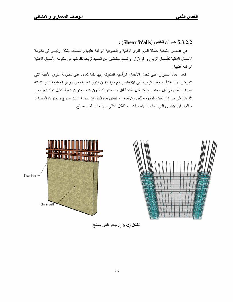
) :Shear Wallsجدران القص ( 5.3.2.2
ھي عناصر إنشائیة حاملة تقاوم القوى األفقیة و العمودیة الواقعة علیھا و تستخدم بشكل رئیسي في مقاومة
األحمال األفقیة كأحمال الریاح و الزالزل و تسلح بطبقتین من الحدید لزیادة كفاءتھا في مقاومة األحمال األفقیة
الواقعة علیھا .
حمال الرأسیة المنقولة إلیھا كما تعمل على مقاومة القوى األفقیة التي تعمل ھذه الجدران على تحمل األ
تتعرض لھا المنشأ و یجب توفرھا في االتجاھین مع مراعاة أن تكون المسافة بین مركز المقاومة الذي تشكلھ
د العزوم و جدران القص في كل اتجاه و مركز ثقل المنشأ أقل ما یمكنو أن تكون ھذه الجدران كافیة لتقلیل تول
آثارھا على جدران المنشأ المقاومة للقوى األفقیة ، و تتمثل ھذه الجدران بجدران بیت الدرج و جدران المصاعد
و الجدران األخرى التي تبدأ من األساسات . والشكل التالي یبین جدار قص مسلح.
): جدار قص مسلح18- 2الشكل (

الفصل الثاني الوصف المعماري واالنشائي
27
:)Foundationsاألساسـات ( 6.3.2.2
بالرغم من أن األساسات ھي أول ما نقوم بتنفیذھا إال أنھا آخر ما نقوم بتصمیمھ . و تعتبر األساسات حلقة
الوصل ما بین العناصر اإلنشائیة في المنشأ و األرض .
و األوزان الواقعة علیھا ، فإن األحمال الواقعة على العقدة تنتقل إلى الجسور منھا إلى و لمعرفة األحمال
األعمدة و أخیرا إلى األساسات التي تقوم بنقلھا و توزیعھا في التربة . بالتالي یكون األساس مسؤول عن تحمل
ج . و تكون ھذه األحمال ھي األحمال األحمال المیتة و الحیة للمنشأ باإلضافة ألحمال الزالزل و الریاح و الثلو
التصمیمیة لألساسات و بناء علیھا و على طبیعة التربة یتم تحدید أبعاد و نوع األساسات المستخدمة.
توجد األساسات على عدة أنواع ھي :
).Isolated Foundationأساسات منفصلة ( .1
).Combined Foundationأساسات مزدوجة ( .2
).Strip Foundationأساسات شریطیة ( .3
) . Raft Foundationأساسات البالطة ( .4
)Piles-Deep Foundationsاألساسات العمیقة ( .5
الفصل الثاني الوصف المعماري واالنشائي
28
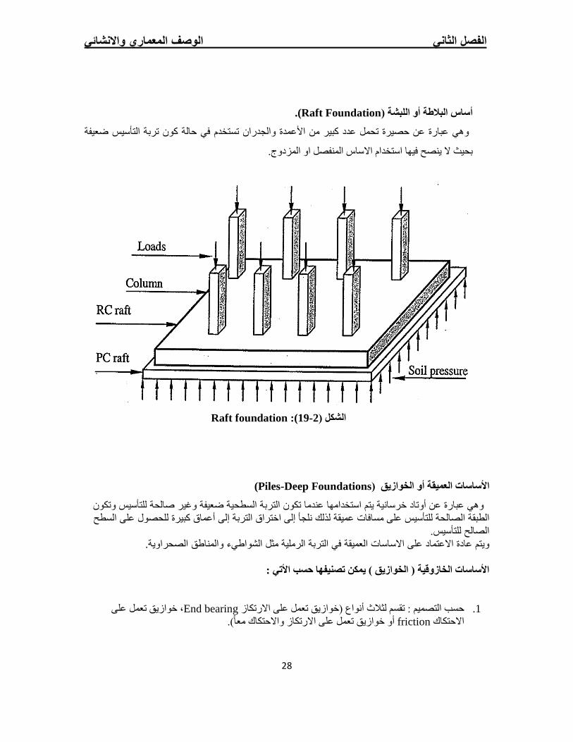
).Raft Foundationأساس البالطة أو اللبشة (
تربة التأسیس ضعیفة كونتستخدم في حالة نوھي عبارة عن حصیرة تحمل عدد كبیر من األعمدة والجدرا
بحیث ال ینصح فیھا استخدام االساس المنفصل او المزدوج.
Raft foundation): 19- 2الشكل (
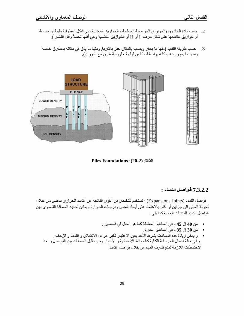
)Piles-Deep Foundationsساسات العمیقة أو الخوازیق (األ
وتكون یس وھي عبارة عن أوتاد خرسانیة یتم استخدامھا عندما تكون التربة السطحیة ضعیفة وغیر صالحة للتأس ول على السطح الطبقة الصالحة للتأسیس على مسافات عمیقة لذلك نلجأ إلى اختراق التربة إلى أعماق كبیرة للحص
الصالح للتأسیس. ویتم عادة االعتماد على االساسات العمیقة في التربة الرملیة مثل الشواطيء والمناطق الصحراویة.
: تصنیفھا حسب األتي األساسات الخازوقیة ( الخوازیق ) یمكن
خوازیق تعمل على ، End bearingحسب التصمیم : تقسم لثالث أنواع (خوازیق تعمل على االرتكاز .1 أو خوازیق تعمل على االرتكاز واالحتكاك معا). frictionاالحتكاك
الفصل الثاني الوصف المعماري واالنشائي
29
حسب مادة الخازوق (الخوازیق الخرسانیة المسلحة ، الخوازیق المعدنیة على شكل اسطوانة ملیئة أو مفرغة .2 أو الخوازیق الخشبیة وھي أقلھا تحمال وأقل انتشارا). Hأو Iأو خوازیق مقاطعھا على شكل حرف
حسب طریقة التنفیذ (منھا ما یحفر ویصب بالمكان حفر بالتفریغ ومنھا ما یدق في مكانھ بمطارق خاصة .3
ومنھا ما یتم زرعھ بمكانھ بواسطة مكابس لولبیة حلزونیة طرق مع الدوران).
Piles Foundations): 2-20كل (الش
فـواصـل التمـدد : 7.3.2.2
تستخدم للتخلص من القوى الناتجة عن التمدد الحراري للمبن`ى م`ن خ`الل ) : Expansions Jointsفواصل التمدد ( تجزئة المبنى الى جزئین أو أكثر باالعتماد على أبع`اد المبن`ى ودرج`ات الح`رارة ویمك`ن تحدی`د المس`افة القص`وى ب`ین
فواصل التمدد للمنشأت العادیة كما یلي :
و الحال في فلسطین .م في المناطق المعتدلة كما ھ 45إل 40من • م في المناطق الحارة . 35إل 30من • و یمكن زیادة ھذه المسافات بشرط األخذ بعین االعتبار تأثیر عوامل االنكماش و التمدد و الزحف . •
خذ أو في حالة أعمال الخرسانة الكتلیة كالحوائط األستنادیة و األسوار یجب تقلیل المسافات بین الفواصل و .االحتیاطات الالزمة لمنع تسرب المیاه من خالل فواصل التمدد
مقدمة في األساسات والتربة لثالــث االفصل
30
الثالــثالفصــــــــــــــل
مقدمة في األساسات والتربة
3
المقدمة 1.3
وتصنیفھاأنواع األساسات 2.3
بھقدرة تحمل التربة والضغط المسموح 3.3
اختیار نوع األساس 4.3
مقدمة في األساسات والتربة لثالــث االفصل
31
ة:المقـدمــ 1.3
ي ساسات العنصر الحامل الرئیسي ف، حیث تعتبر األ ساسات دورا أساسیا بین العلوم الھندسیةعلم األیحتل
الواقعة علیھا من عناصر المنشأة الى التربة التي تستند الیھا وتوزیعھا في التربة حمالالمنشأة، فھي تنقل األ
ساسات یدفع إن تصمیم األف ، وعلى ذلك لمنشأةباعتبارھا تشكل نصف الفراغ الالنھائي، لضمان االستقرار الكلي ل
االجھاد حمال من جھة وبنا الى التعامل مع عالقات أكثر تعقیدا (من تصمیم العناصر االخرى للمنشأة التي تربط األ
خول كبر عددا، فدأ). وبالتالي التعامل مع متغیرات ثابتة ال تختلف باختالف النظریاتمن جھة اخرى بعالقة
مر أة جدیدة في التصمیم یجعل الحاجة الى التعامل مع منظومة المتغیرات التي تشكل نظریات المتانة التربة كماد
بعاد ألساسات واساسات كحساب إنشائي ، الختیار نوع األ، والجمع بین التربة كعلم مستقل وبین األ ال بد منھ
، نشائیة للمبنى من جھةت من العناصر اإلفعال واالجھاداالھندسیة مع مراعاة نوعیة التربة والھبوط وردود األ
مان والجودى االقتصادیة من جھة اخرى. وتحقیق األ
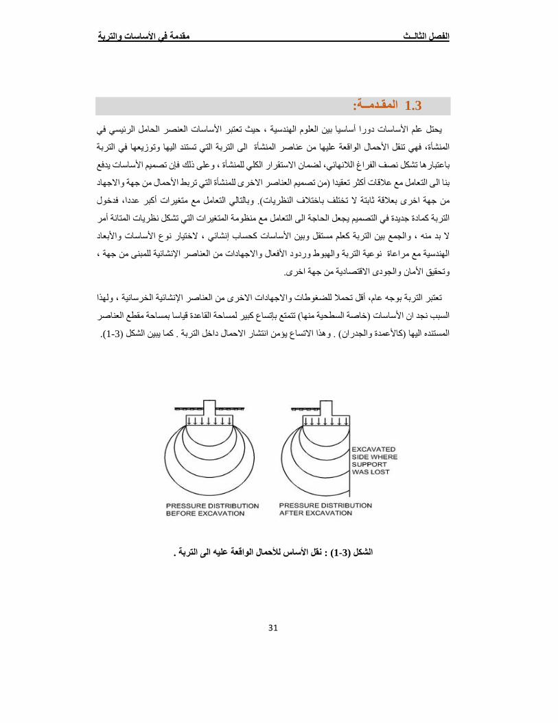
ولھذا ، نشائیة الخرسانیةقل تحمال للضغوطات واالجھادات االخرى من العناصر اإلأتعتبر التربة بوجھ عام،
ع العناصر ة مقطالقاعدة قیاسا بمساحساسات (خاصة السطحیة منھا) تتمتع بإتساع كبیر لمساحة السبب نجد ان األ
.)1-3كاألعمدة والجدران) . وھذا االتساع یؤمن انتشار االحمال داخل التربة . كما یبین الشكل (المستنده الیھا (
نقل األساس لألحمال الواقعة علیھ الى التربة . :) 1-3( الشكل
مقدمة في األساسات والتربة لثالــث االفصل
32
ء ویتم نشااالقتصادیة لإلق األمان الكافي والمحقق للشروط تحقین الھدف النھائي لتصمیم ھذه العناصر ھو إ
سیس التي تتناسب مع طبیعة التربة ونوع المنشأة أعماق التأبعادھا وأساسات المناسبة ونوع األذلك باختیار
دساسات یلعب دورا فاعال في تحدین فن التصمیم في األأحمال المطبقة علیھا وغیرھا وفي ھذا المساق نجد واأل
. ساسات المختارةاأل نوع
وتصنیفھا:أنواع األساسات 3.2
تصنف األساسات بوجھ عام الـى :
: حیث ھي عبارة عن أساسات تنفذ على أعماق ) Shallow Foundationساسات السطحیة ( األ .1
ویستعمل ھذا النوع قریبة من سطح األرض حیث یكون عمق التأسیس أقل من ضعف عرض األساس
تمتاز األساسات السطحیة من األساسات للتربة ذات الطبقات القویة القریبة من سطح األرض.
: تسgggتعمل عندما تكون طبقات التربة القریبة من )Deep Foundationس<<<اس<<<ات العمیقة ( اال .2
علیھا كبیرة.سطح األرض ضعیفة وتكون األحمال
تمتاز األسggggاسggggات السggggطحیة بسggggھولة التنفیذ وكثرة االسggggتخدام وأقل تكلفة اقتصggggادیة بالمقارنة مع •
.األساسات العمیقة
كبیرة حتى نصل إلى التربة القویة أحیانا ألھمیة المنشأ واعتبارات األمان ننزل إلى أعماق •
أنواع األساسات السطحیة :
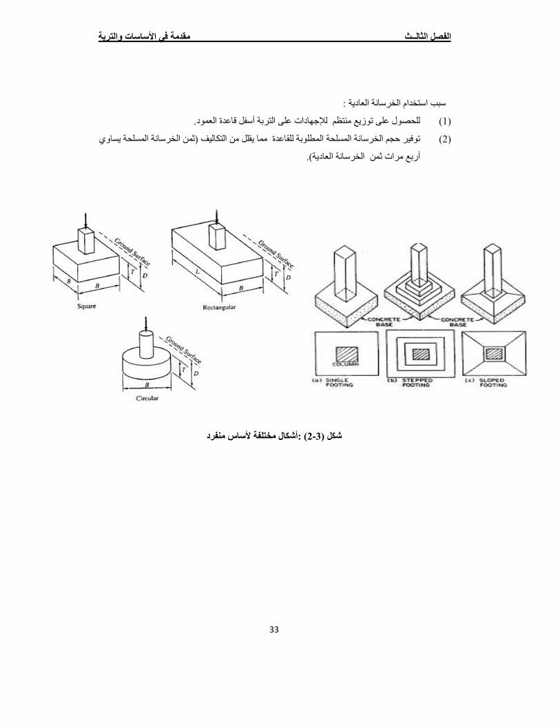
).Isolated Footingاألساسات المنفردة ( .1
تسggggتخدم كأسggggاس لألعمدة الخرسggggانیة والمعدنیة منھا المربع والمسggggتطیل والدائري غالبا یكون شggggكل
تتكون األسggggggاسggggggات القاعدة نفس شggggggكل العمود لتحسggggggن طریقة توزیع االجھادات من العمود للقاعدة.
و المنفصلة من جزئین:أالمنفردة
.من الخرسانة المسلحة يالجزء العلو •
.من الخرسانة العادیة يالجزء السفل •
مقدمة في األساسات والتربة لثالــث االفصل
33
سبب استخدام الخرسانة العادیة :
للحصول على توزیع منتظم لإلجھادات على التربة أسفل قاعدة العمود. )1(
ساوي یتوفیر حجم الخرسانة المسلحة المطلوبة للقاعدة مما یقلل من التكالیف (ثمن الخرسانة المسلحة )2(
مرات ثمن الخرسانة العادیة). أربع
) :أشكال مختلفة ألساس منفرد2-3شكل (
مقدمة في األساسات والتربة لثالــث االفصل
34
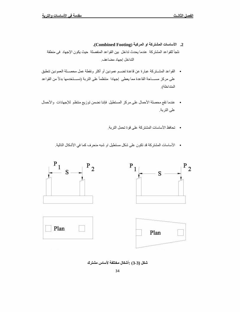
).Combined Footingاألساسات المشتركة او المركبة ( .2
المشتركة عندما یحدث تداخل بین القواعد المنفصلة حیث یكون اإلجھاد فى منطقة لجأ للقواعد ن
التداخل إجھاد مضاعف.
ر ونقطة عمل محصggggلة العمودین تنطبق ثالقواعد المشggggتركة عبارة عن قاعدة تضggggم عمودین أو أك •
من القواعد التربة (نسgggggggتخدمھا بدال ىعلى مركز مسgggggggاحة القاعدة مما یعطى إجھادا منتظما عل
المتداخلة).
عندما تقع محصلة األحمال على مركز المستطیل فإننا نضمن توزیع منتظم لإلجھادات واألحمال •
على التربة.
تحافظ األساسات المشتركة على قوة تحمل التربة. •
األساسات المشتركة قد تكون على شكل مستطیل او شبھ منحرف كما في األشكال التالیة. •
) :أشكال مختلفة ألساس مشترك3-3شكل (
مقدمة في األساسات والتربة لثالــث االفصل
35
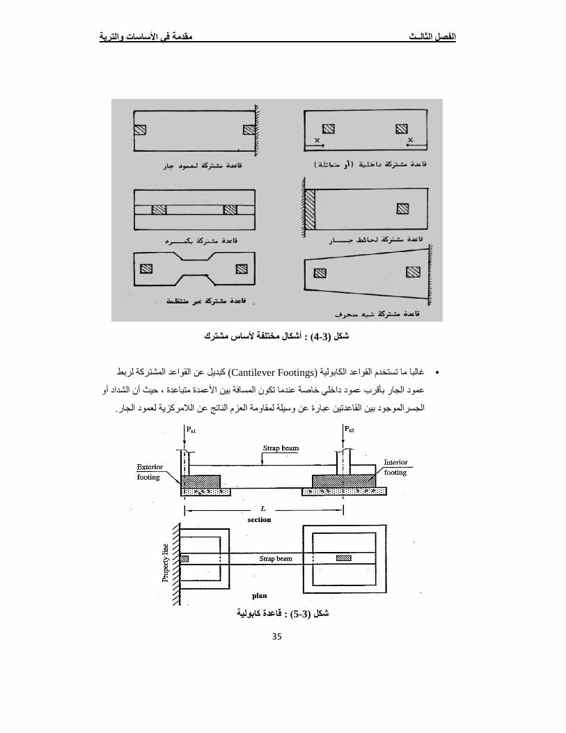
كبدیل عن القواعد المشتركة لربط )Cantilever Footings( غالبا ما تستخدم القواعد الكابولیة •
أو ن الشداد أعمود الجار بأقرب عمود داخلي خاصة عندما تكون المسافة بین األعمدة متباعدة ، حیث
الناتج عن الالمركزیة لعمود الجار. العزم لموجود بین القاعدتین عبارة عن وسیلة لمقاومةالجسرا
) : أشكال مختلفة ألساس مشترك4-3شكل (
) : قاعدة كابولیة5-3شكل (
مقدمة في األساسات والتربة لثالــث االفصل
36
).Continuous Footing( األساس المستمر .3
ن حیاة ، وفي بعض األیساسات الشریطایضا باألأوھي االساسات التي تحمل جدارا مستمرا، وتدعى
ساس مستمر. ) نموذج أل6-3ساسات المستمرة كما یبین شكل (ساسات المشتركة نوعا من األتعتبر األ
) : نموذج ألساس مستمر 6-3شكل(
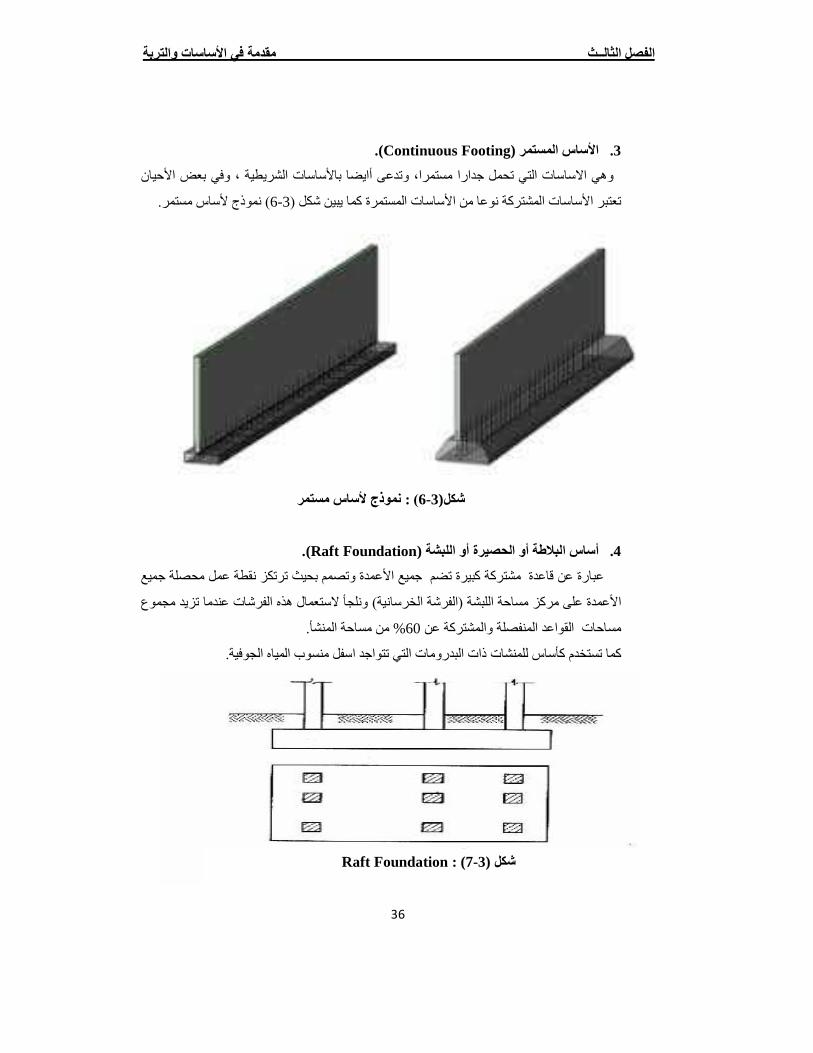
).Raft Foundation( أو اللبشة أساس البالطة أو الحصیرة .4
میع جعمدة وتصمم بحیث ترتكز نقطة عمل محصلة األعبارة عن قاعدة مشتركة كبیرة تضم جمیع
األعمدة على مركز مساحة اللبشة (الفرشة الخرسانیة) ونلجأ الستعمال ھذه الفرشات عندما تزید مجموع
من مساحة المنشأ. %60مساحات القواعد المنفصلة والمشتركة عن
المیاه الجوفیة.كما تستخدم كأساس للمنشات ذات البدرومات التي تتواجد اسفل منسوب
Raft Foundation) : 7-3شكل (
مقدمة في األساسات والتربة لثالــث االفصل
37
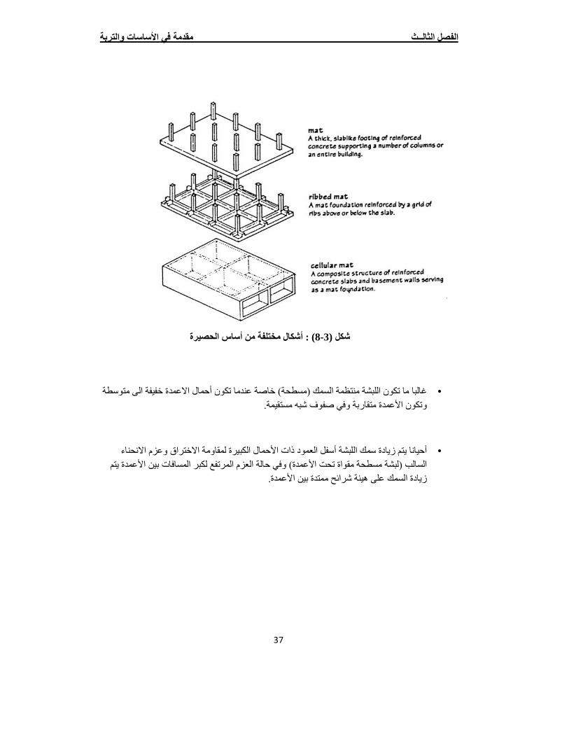
غالبا ما تكون اللبشة منتظمة السمك (مسطحة) خاصة عندما تكون أحمال االعمدة خفیفة الى متوسطة • وتكون األعمدة متقاربة وفي صفوف شبھ مستقیمة.
األحمال الكبیرة لمقاومة االختراق وعزم االنحناء أحیانا یتم زیادة سمك اللبشة أسفل العمود ذات •السالب (لبشة مسطحة مقواة تحت األعمدة) وفي حالة العزم المرتفع لكبر المسافات بین األعمدة یتم
زیادة السمك على ھیئة شرائح ممتدة بین األعمدة.
شكال مختلفة من أساس الحصیرةأ) : 8-3شكل (
مقدمة في األساسات والتربة لثالــث االفصل
38
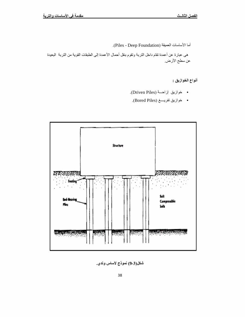
).Piles - Deep Foundationأما األساسات العمیقة (
ھى عبارة عن أعمدة تقام داخل التربة وتقوم بنقل أحمال األعمدة إلى الطبقات القویة من التربة البعیدة عن سطح األرض.
أنواع الخوازیق :
).Driven Piles( خوازیق إزاحـــة •
).Bored Piles( خوازیق تفریــــغ •
) نموذج ألساس وتدي.9-3شكل(
مقدمة في األساسات والتربة لثالــث االفصل
39
بھ:تحمل التربة والضغط المسموح قدرة 3.3
:)Soilالتربة ( 1.3.3
طینیة). –رملیة –قویة –تتكون من طبقات حسب التكوین الجیولوجي لھا (تربة ضعیفة
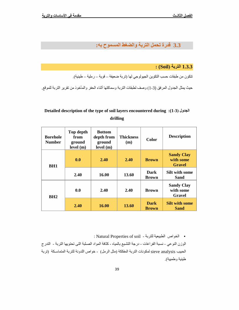
المأخوذ من تقریر التربة للموقع.وقات التربة وسماكتھا أثناء الحفر ) وصف لطب1-3( المرفق حیث یمثل الجدول
Detailed description of the type of soil layers encountered during :)1-3الجدول (
drilling
Borehole Number
Top depth from
ground level (m)
Bottom depth from
ground level (m)
Thickness (m)
Color Description
BH1 0.0 2.40 2.40 Brown
Sandy Clay with some
Gravel
2.40 16.00 13.60 Dark Brown
Silt with some Sand
BH2
0.0 2.40 2.40 Brown Sandy Clay with some
Gravel
2.40 16.00 13.60 Dark Brown
Silt with some Sand
Natural Properties of soil : -لخواص الطبیعیة للتربة ا •
التدرج -كثافة المواد الصggلبة التى تحتویھا التربة -درجة التشggبع بالمیاه -نسggبة الفراغات - يالوزن النوع
خواص اللدونة للتربة المتماسgggكة (تربة -لمكونات التربة المفككة (مثل الرمل) sieve analysisالحبیب
طینیة وطمییة).

مقدمة في األساسات والتربة لثالــث االفصل
40
:Soil Investigation -فحص التربة •
ھى العملیة التى یتم فیھا اسggggggتخراج طبقات التربة أو عینات سggggggلیمة (كما ھى موجودة فى الطبیعة)
الختبارھا بالمعمل وتحدید خواصھا الطبیعیة والمیكانیكیة. منھا
ویتم ذلك عن طریق عمل جسggggات بطریقة میكانیكیة أو یدویة واسggggتخراج عینات من التربة من كل
بواسggطة أجھزة خاصggة ویتم تفریغ العینات من ھذه األجھزة وحفظھا فى أكیاس من البالسggتیك يمتر طول
ق إذا كانت العینات غیر سgggggggلیمة (مختلفة) أو تغلیفھا بالشgggggggمع إذا كانت العینات سgggggggلیمة غالالمحكمة اال
ة خالل فحص الترب لالحتفاظ بنسgggggggبة الرطوبة فیھا لحین اختبارھا فى المعمل وإجراء تجارب علیھا ومن
: یمكن التعرف على
i. منسوب المیاه الجوفیة - Ground water level : وتؤخذ عینات منھا لتحلیلھا كیماویا ولتحدید
أنواع األمالح الضgggggارة بالخرسgggggانة مثل الكبریتات التى تعمل على تآكل األسgggggاسgggggات وكلورید
لحة . یسبب صدأ الحدید فى الخرسانة المس يالصودیوم الذ
ii. اسggggتوى األسggggتحدید مس- : Foundation Level یسggggوجھد التأس (طح األرضggggبعده عن س )
(أقصggggى إجھاد تتحملھ التربة وبعده یحدث االنھیار) وتحدید نوع األسggggاس المراد اسggggتخدامھ في
المنشأة.
iii. اب الھبوط المنتظرgggggحس- Expected Settlement أ نتیجة تحمیلھ على التربةgggggویكون للمنش
ھgذا الھبوط كبیرا إذا كgان التحمیgل كبیر على التربgة وقلیال إذا كgان التحمیgل قلیgل على التربgة
ویجب أن یكون ھذا الھبوط أقل من المسgggggggموح بھ فى المواصgggggggفات حتى ال یحدث تصgggggggدعات
.ىوشروخ فى المبن
مقدمة في األساسات والتربة لثالــث االفصل
41
األحمال:تربة وتوزیع لل الجھاد المسموح بھإ 2.3.3
ساسات الصلبة والمرنة ال یكون خطیا، بل یخضع الى حمال على التربة تحت األن توزیع األأمن المعروف
یة نھ یتم اللجوء الى طرق تقریبأال إ، عالوة على ذلك فإن ھذه المسألة لیست محددة. عالقات وصیغ ریاضیة معقدة
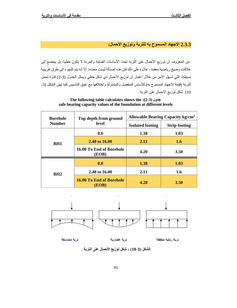
قدرة تحمل ) 2-3(یمثل الجدول حمال ذي شكل خطي وأن توزیع األ بسیطة، التي تسھل االمر من خالل اعتبار
-3كل (ما یبین الشكسیس أ) لألساس المنفصل والمشترك واختالفھا مع عمق التقیمة االجھاد المسموح بھالتربة (
حمال على التربة .توزیع األشكل ) 10
Borehole Number
Top depth from ground level
Allowable Bearing Capacity kg/cm2
Isolated footing Strip footing
BH1
0.0 1.38 1.03
2. 04 to 16.00 2.11 1.6
16.00 To End of Borehole (EOB) 4.20 3.50
BH2
0.0 1.38 1.03
2. 04 to 16.00 2.11 1.6
16.00 To End of Borehole (EOB)
4.20 3.50
) : شكل توزیع األحمال على التربة .10-3الشكل (
The following table calculates shows the): 2-3جدول (safe bearing capacity values of the foundation at different levels
مقدمة في األساسات والتربة لثالــث االفصل
42
األساس:اختیار نوع 4.3
مات عن المعلوساسات التي ستقام علیھا المنشأة في جمع تتمثل االجراءات الواجب اتباعھا قبل اختیار نوع األ
ساسات اضافة الى الجدوى االقتصادیة عن حمال التي ستتعرض لھا األتربة التأسیس وموقع المنشأة وطبیعة األ
سعار المواد االولیة وتكالیف االنشاء وغیرھا . أ
ةھم ھذه المعلومات لكونھا على صلة مباشرة بعملیأن دراسة موقع المنشأة وتربة التأسیس، تعتبر من أال إ
الموقع والتأكد ، بغیة معاینة ساسات القیام بزیارة میدانیة الى الموقعالتصمیم لذلك یتوجب علینا قبل تحدید نوع األ
فة عمال الحفر والصب اضاأولي عن كیفیة تنفیذ أو عدم وجود منشآت مجاورة وبالتالي تكوین تصور أمن وجود
لمنعھا من االنھیار.الى وضع اقتراحات مبدئیة عن طریق تدعیم الحفریات
ما من حیث تحدید طبیعة التربة وخصائصھا المختلفة فإن ذلك یجري بواسطة آبار اختباریة تحفر في الموقع، أ
) ضخمة تسمى الحفارة لمعرفة عمق الصخر اذا حیث یتم ذلك عن طریق آالت (ماكینات وتادأو بواسطة دق األ
) ... للحصول على نتائج اختبار فحص التربة وخصائصھا وتصنیف و اذا كانت توجد میاه جوفیة (ان وجدتأوجد
نوع التربة.
ھم المعلومات التي یحتاجھا المصمم عن تربة التأسیس : أومن
. “allQ ”والتحمل المسموح بھ “ullQ ”قدرة التحمل العظمى للتربة -1
) إن وجدت . Water Tableارتفاع منسوب المیاه الجوفیة ( -2
الھبوط المسموح بھ للتربة . -3
عمق التأسیس المقترح . -4
الخصاص االخرى للتربة كاالحتكاك والتماسك وغیرھا. -5
ور ، یلعب الد ساساتالمطبقة وشكل توزیعھا على األ حمالان ھذه المعلومات اضافة الى طبیعة المنشأة وقیم األ
الرئیسي في اختیار نوع االساس .
Structural Analysis & Design Chapter 4
43
Chapter 4
Structural Analysis & DDeessiiggnn
4
4 .1 Introduction.
4.2 Design Method and Requirements.
4.3 Factored Loads.
4.4 Determination of Slab Thickness.
4.5 Loads Calculations.
4.6 Design the Raft Foundation.
4.7 Design the Pile Foundation.
Structural Analysis & Design Chapter 4
44
4.1 Introduction:
Concrete is the only major building material that can be delivered to the job site in a plastic state. This unique quality makes concrete desirable as a building material because it can be molded to virtually any form or shape.
Concrete used in most construction work is reinforced with steel. When concrete structure members must resist extreme tensile stresses, steel supplies the necessary strength. Steel is embedded in the concrete in the form of a mesh, or roughened or twisted bars. A bond forms between the steel and the concrete, and stresses can be transferred between both components.
The project consists of several structural elements but in this project we will design the Raft Foundation) Determine the thickness of Raft and reinforced it) by using ACI Code and software design – Safe v. 12.0 and determine the consolidation settlement of raft foundation.
4-2 Design method and requirements:
The design strength provided by a member is calculated in accordance with the requirements and assumptions of ACI Code (318 - 08).
Strength design method: In ultimate strength design method, the service loads are increased by factors to obtain the load at which failure is considered to be occurring. This load called factored load or factored service load. The structure or structural element is then proportioned such that the strength is reached when factored load is acting. The computation of this strength takes into account the nonlinear stress-strain behavior of concrete. The strength design method is expressed by the following,
Strength Provided ≥ Strength Required To Carry Factored Loads
Structural Analysis & Design Chapter 4
45
Loads Factored4.3
The factored loads for members in our project are determined by:
Wu = 1.2 DL + 1.6 LL ACI Code 318-08 (9.2.1). NOTE: ��� = �� �. �� = �� � Will be used in the design and calculations.
4.4 Determination of Slab Thickness
1. Determination of Slab Thickness for One Way Rib Slab.
The structure may be exposed to different loads such as dead and live loads. The value of the load depends on the structure type and the intended use.
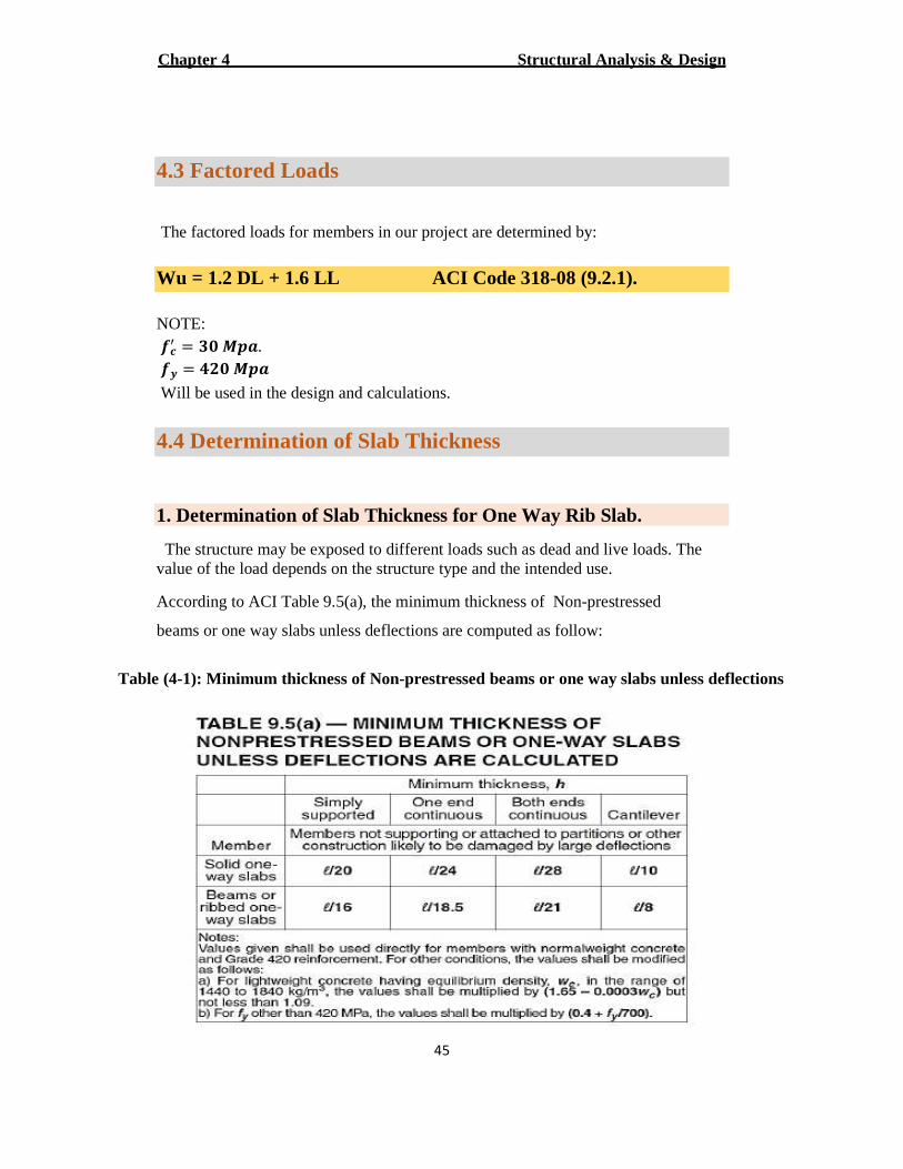
According to ACI Table 9.5(a), the minimum thickness of Non-prestressed
beams or one way slabs unless deflections are computed as follow:
Table (4-1): Minimum thickness of Non-prestressed beams or one way slabs unless deflections
Structural Analysis & Design Chapter 4
46
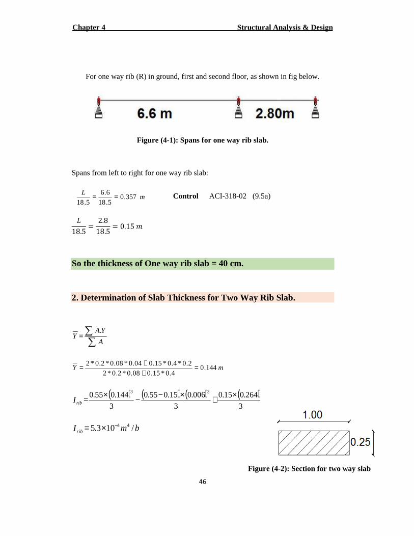
For one way rib (R) in ground, first and second floor, as shown in fig below.
Figure (4-1): Spans for one way rib slab.
Spans from left to right for one way rib slab:
mL
357.05.18
6.6
5.18== Control ACI-318-02 (9.5a)
�18.5 = 2.8
18.5 = 0.15 �
So the thickness of One way rib slab = 40 cm.
2. Determination of Slab Thickness for Two Way Rib Slab.
∑∑=
A
YAY
.
mY 144.04.0*15.008.0*2.0*2
2.0*4.0*15.004.0*08.0*2.0*2 =++=
( ) ( ) ( ) ( )3
264.015.0
3
006.015.055.0
3
144.055.0 333 ×+×−−×=ribI
bmI rib /103.5 44−×=
Figure (4-2): Section for two way slab
Structural Analysis & Design Chapter 4
47
444
108928.955.0
103.5mI slab
−−
×=××=
3
2
3331
10*33.5
10*67.2)40.0(*5.0*12
1
12
1
−
−
=
===
b
b
I
bhI
6.01089
1033.5
3.01089
1067.2
4
31
2
4
31
1
=××==
=××==
−
−
−
−
s
b
s
b
I
I
I
I
α
α
245.02.022.0
45.02
6.03.0
221
<<==><<
=+=+
=
α
ααα m
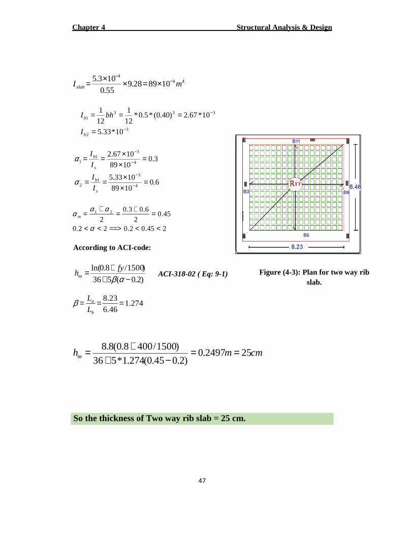
According to ACI-code:
)2.0(536
)1500/8.0ln(
−++=
αβfy
hm ACI-318-02 ( Eq: 9-1)
274.146.6
23.8 ===b
a
L
Lβ
cmmhm 252497.0)2.045.0(274.1*536
)1500/4008.0(8.8 ==−+
+=
So the thickness of Two way rib slab = 25 cm.
Figure (4-3): Plan for two way rib slab.
Structural Analysis & Design Chapter 4
48
4.5 Loads Calculations
1. Calculation of Dead Loads:
For the one-way and two-way ribbed slabs, the total dead load to be used in the
analysis and design is calculated as follows:
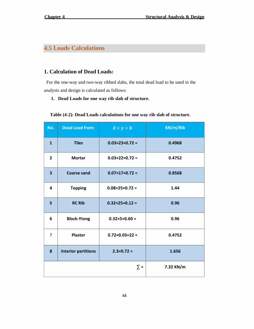
1. Dead Loads for one way rib slab of structure.
Table (4-2): Dead Loads calculations for one way rib slab of structure.
KN/m/Rib � × � × � Dead Load from: No.
0.4968 0.03×23×0.72 = Tiles 1
0.4752 0.03×22×0.72 = Mortar 2
0.8568 0.07×17×0.72 = Coarse sand 3
1.44 0.08×25×0.72 = Topping 4
0.96 0.32×25×0.12 = RC Rib 5
0.96 0.32×5×0.60 = Block-Ytong 6
0.4752 0.72×0.03×22 = Plaster 7
1.656 2.3×0.72 = Interior partitions 8
7.32 KN/m =∑
Structural Analysis & Design Chapter 4
49
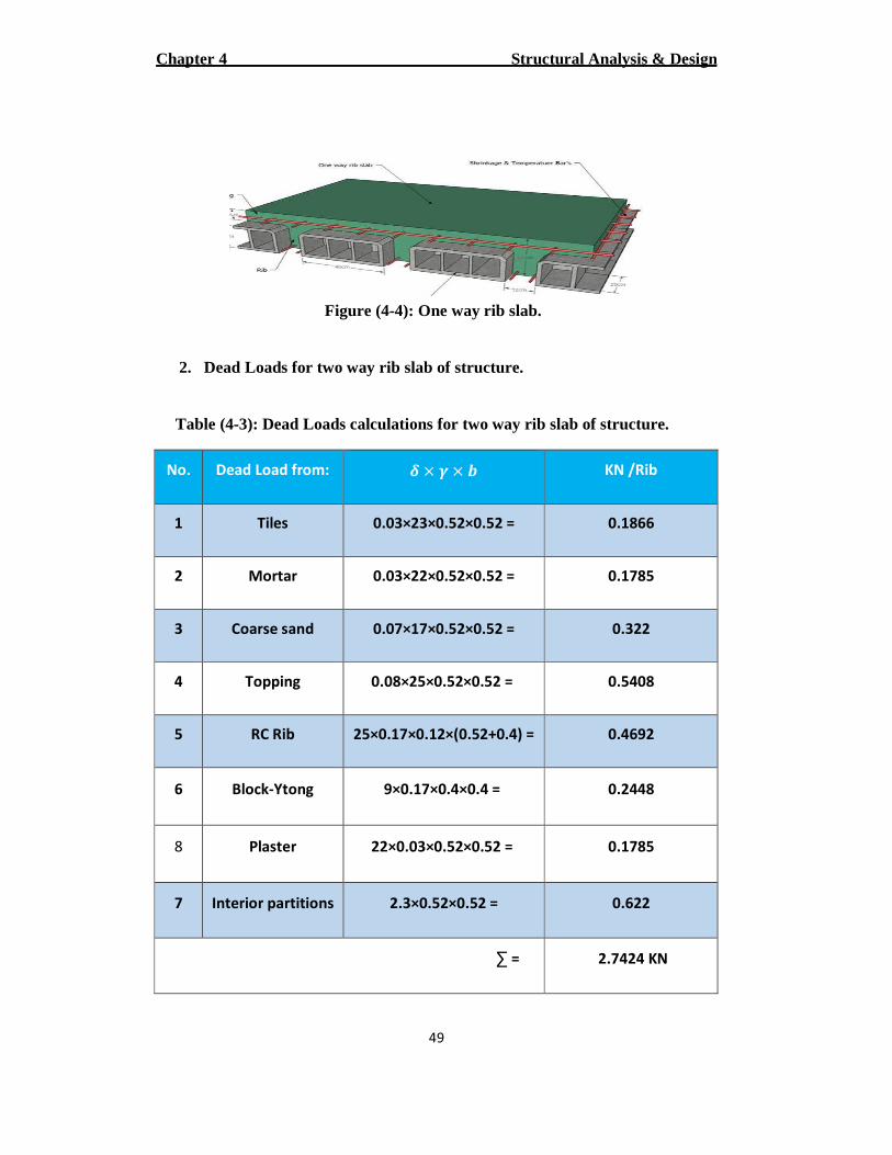
Figure (4-4): One way rib slab.
2. Dead Loads for two way rib slab of structure.
Table (4-3): Dead Loads calculations for two way rib slab of structure.
KN /Rib � × � × � Dead Load from: No.
0.1866 0.03×23×0.52×0.52 = Tiles 1
0.1785 0.03×22×0.52×0.52 = Mortar 2
0.322 0.07×17×0.52×0.52 = Coarse sand 3
0.5408 0.08×25×0.52×0.52 = Topping 4
0.4692 25×0.17×0.12×(0.52+0.4) = RC Rib 5
0.2448 9×0.17×0.4×0.4 = Block-Ytong 6
0.1785 22×0.03×0.52×0.52 = Plaster 8
0.622 2.3×0.52×0.52 = Interior partitions 7
2.7424 KN =∑
Structural Analysis & Design Chapter 4
50
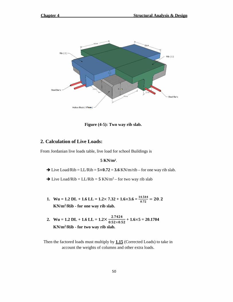
Figure (4-5): Two way rib slab.
2. Calculation of Live Loads:
From Jordanian live loads table, live load for school Buildings is
5 KN/m².
� Live Load/Rib = LL/Rib = 5×0.72 = 3.6 KN/m/rib – for one way rib slab.
� Live Load/Rib = LL/Rib = 5 KN/m2 – for two way rib slab
1. Wu = 1.2 DL + 1.6 LL = 1.2× 7.32 + 1.6×3.6 = � .�
�.�� = ��. �
KN/m2/Rib - for one way rib slab.
2. Wu = 1.2 DL + 1.6 LL = 1.2× �.� � �.��×�.�� + 1.6×5 = 20.1704
KN/m2/Rib - for two way rib slab.
Then the factored loads must multiply by 1.15 (Corrected Loads) to take in account the weights of columns and other extra loads.
Structural Analysis & Design Chapter 4
51
1. Wu = 20.2 × 1.15 = 23.23 KN.
2. Wu = 20.1704 × 1.15 = 23.2 KN.
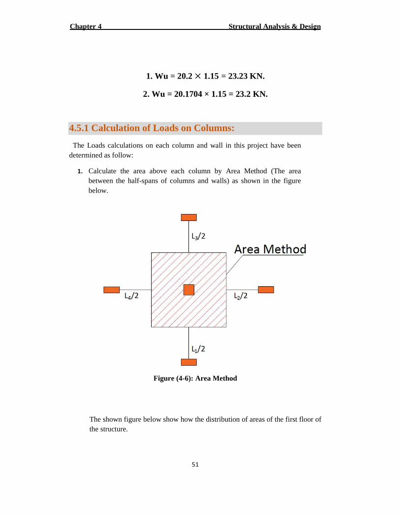
4.5.1 Calculation of Loads on Columns:
The Loads calculations on each column and wall in this project have been determined as follow:
1. Calculate the area above each column by Area Method (The area between the half-spans of columns and walls) as shown in the figure below.
Figure (4-6): Area Method
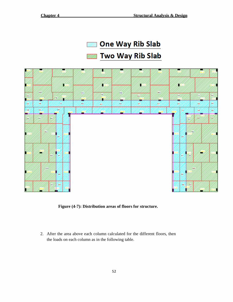
The shown figure below show how the distribution of areas of the first floor of the structure.
Structural Analysis & Design Chapter 4
52
Figure (4-7): Distribution areas of floors for structure.
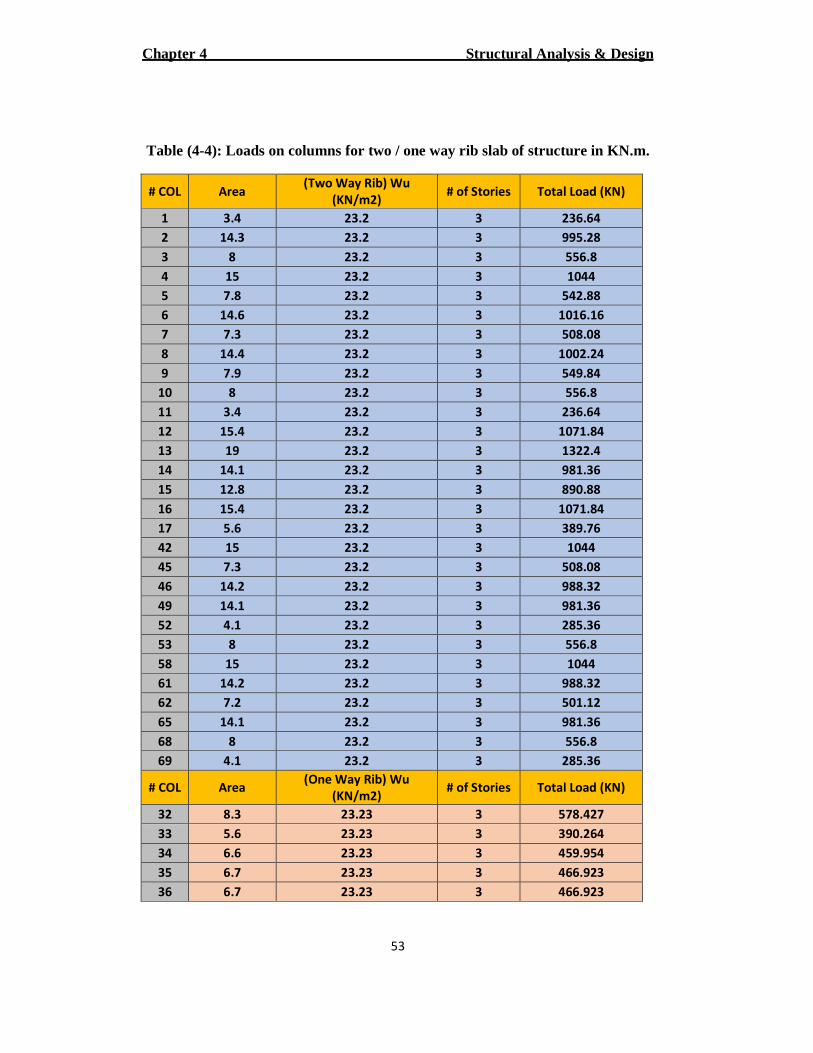
2. After the area above each column calculated for the different floors, then the loads on each column as in the following table.
Structural Analysis & Design Chapter 4
53
Table (4-4): Loads on columns for two / one way rib slab of structure in KN.m.
# COL Area (Two Way Rib) Wu
(KN/m2) # of Stories Total Load (KN)
1 3.4 23.2 3 236.64
2 14.3 23.2 3 995.28
3 8 23.2 3 556.8
4 15 23.2 3 1044
5 7.8 23.2 3 542.88
6 14.6 23.2 3 1016.16
7 7.3 23.2 3 508.08
8 14.4 23.2 3 1002.24
9 7.9 23.2 3 549.84
10 8 23.2 3 556.8
11 3.4 23.2 3 236.64
12 15.4 23.2 3 1071.84
13 19 23.2 3 1322.4
14 14.1 23.2 3 981.36
15 12.8 23.2 3 890.88
16 15.4 23.2 3 1071.84
17 5.6 23.2 3 389.76
42 15 23.2 3 1044
45 7.3 23.2 3 508.08
46 14.2 23.2 3 988.32
49 14.1 23.2 3 981.36
52 4.1 23.2 3 285.36
53 8 23.2 3 556.8
58 15 23.2 3 1044
61 14.2 23.2 3 988.32
62 7.2 23.2 3 501.12
65 14.1 23.2 3 981.36
68 8 23.2 3 556.8
69 4.1 23.2 3 285.36
# COL Area (One Way Rib) Wu
(KN/m2) # of Stories Total Load (KN)
32 8.3 23.23 3 578.427
33 5.6 23.23 3 390.264
34 6.6 23.23 3 459.954
35 6.7 23.23 3 466.923
36 6.7 23.23 3 466.923
Structural Analysis & Design Chapter 4
54
37 5.6 23.23 3 390.264
38 7.6 23.23 3 529.644
44 6.4 23.23 3 446.016
48 6.6 23.23 3 459.954
51 6.4 23.23 3 446.016
55 3.7 23.23 3 257.853
56 6.4 23.23 3 446.016
59 6.6 23.23 3 459.954
63 6.4 23.23 3 446.016
66 3.7 23.23 3 257.853
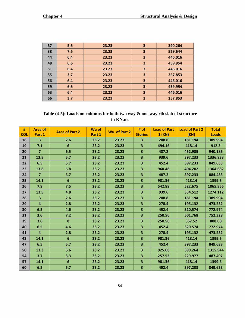
Table (4-5): Loads on columns for both two way & one way rib slab of structure in KN.m.
#
COL
Area of
Part 1 Area of Part 2
Wu of
Part 1 Wu of Part 2
# of
Stories
Load of Part
1 (KN)
Load of Part 2
(KN)
Total
Loads
18 3 2.6 23.2 23.23 3 208.8 181.194 389.994
19 7.1 6 23.2 23.23 3 494.16 418.14 912.3
20 7 6.5 23.2 23.23 3 487.2 452.985 940.185
21 13.5 5.7 23.2 23.23 3 939.6 397.233 1336.833
22 6.5 5.7 23.2 23.23 3 452.4 397.233 849.633
23 13.8 5.8 23.2 23.23 3 960.48 404.202 1364.682
24 7 5.7 23.2 23.23 3 487.2 397.233 884.433
25 14.1 6 23.2 23.23 3 981.36 418.14 1399.5
26 7.8 7.5 23.2 23.23 3 542.88 522.675 1065.555
27 13.5 4.8 23.2 23.23 3 939.6 334.512 1274.112
28 3 2.6 23.2 23.23 3 208.8 181.194 389.994
29 4 2.8 23.2 23.23 3 278.4 195.132 473.532
30 6.5 4.6 23.2 23.23 3 452.4 320.574 772.974
31 3.6 7.2 23.2 23.23 3 250.56 501.768 752.328
39 3.6 8 23.2 23.23 3 250.56 557.52 808.08
40 6.5 4.6 23.2 23.23 3 452.4 320.574 772.974
41 4 2.8 23.2 23.23 3 278.4 195.132 473.532
43 14.1 6 23.2 23.23 3 981.36 418.14 1399.5
47 6.5 5.7 23.2 23.23 3 452.4 397.233 849.633
50 13.3 5.6 23.2 23.23 3 925.68 390.264 1315.944
54 3.7 3.3 23.2 23.23 3 257.52 229.977 487.497
57 14.1 6 23.2 23.23 3 981.36 418.14 1399.5
60 6.5 5.7 23.2 23.23 3 452.4 397.233 849.633
Structural Analysis & Design Chapter 4
55
64 13.3 5.6 23.2 23.23 3 925.68 390.264 1315.944
67 3.7 3.3 23.2 23.23 3 257.52 229.977 487.497
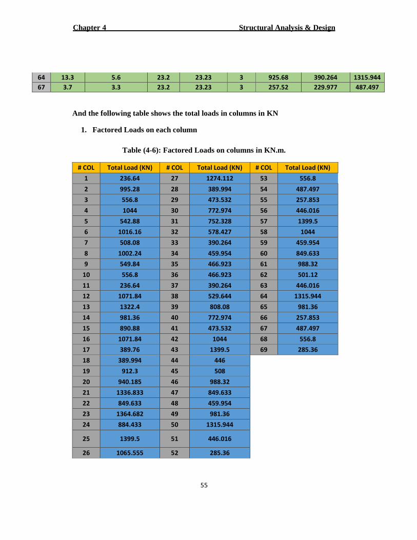
And the following table shows the total loads in columns in KN
1. Factored Loads on each column
Table (4-6): Factored Loads on columns in KN.m.
# COL Total Load (KN) # COL Total Load (KN) # COL Total Load (KN)
1 236.64 27 1274.112 53 556.8
2 995.28 28 389.994 54 487.497
3 556.8 29 473.532 55 257.853
4 1044 30 772.974 56 446.016
5 542.88 31 752.328 57 1399.5
6 1016.16 32 578.427 58 1044
7 508.08 33 390.264 59 459.954
8 1002.24 34 459.954 60 849.633
9 549.84 35 466.923 61 988.32
10 556.8 36 466.923 62 501.12
11 236.64 37 390.264 63 446.016
12 1071.84 38 529.644 64 1315.944
13 1322.4 39 808.08 65 981.36
14 981.36 40 772.974 66 257.853
15 890.88 41 473.532 67 487.497
16 1071.84 42 1044 68 556.8
17 389.76 43 1399.5 69 285.36
18 389.994 44 446
19 912.3 45 508
20 940.185 46 988.32
21 1336.833 47 849.633
22 849.633 48 459.954
23 1364.682 49 981.36
24 884.433 50 1315.944
25 1399.5 51 446.016
26 1065.555 52 285.36
Structural Analysis & Design Chapter 4
56
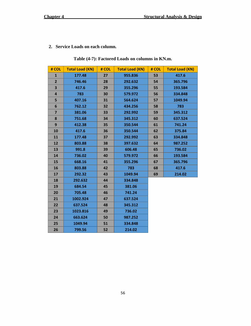
2. Service Loads on each column.
Table (4-7): Factored Loads on columns in KN.m.
# COL Total Load (KN) # COL Total Load (KN) # COL Total Load (KN)
1 177.48 27 955.836 53 417.6
2 746.46 28 292.632 54 365.796
3 417.6 29 355.296 55 193.584
4 783 30 579.972 56 334.848
5 407.16 31 564.624 57 1049.94
6 762.12 32 434.256 58 783
7 381.06 33 292.992 59 345.312
8 751.68 34 345.312 60 637.524
9 412.38 35 350.544 61 741.24
10 417.6 36 350.544 62 375.84
11 177.48 37 292.992 63 334.848
12 803.88 38 397.632 64 987.252
13 991.8 39 606.48 65 736.02
14 736.02 40 579.972 66 193.584
15 668.16 41 355.296 67 365.796
16 803.88 42 783 68 417.6
17 292.32 43 1049.94 69 214.02
18 292.632 44 334.848
19 684.54 45 381.06
20 705.48 46 741.24
21 1002.924 47 637.524
22 637.524 48 345.312
23 1023.816 49 736.02
24 663.624 50 987.252
25 1049.94 51 334.848
26 799.56 52 214.02
Structural Analysis & Design Chapter 4
57
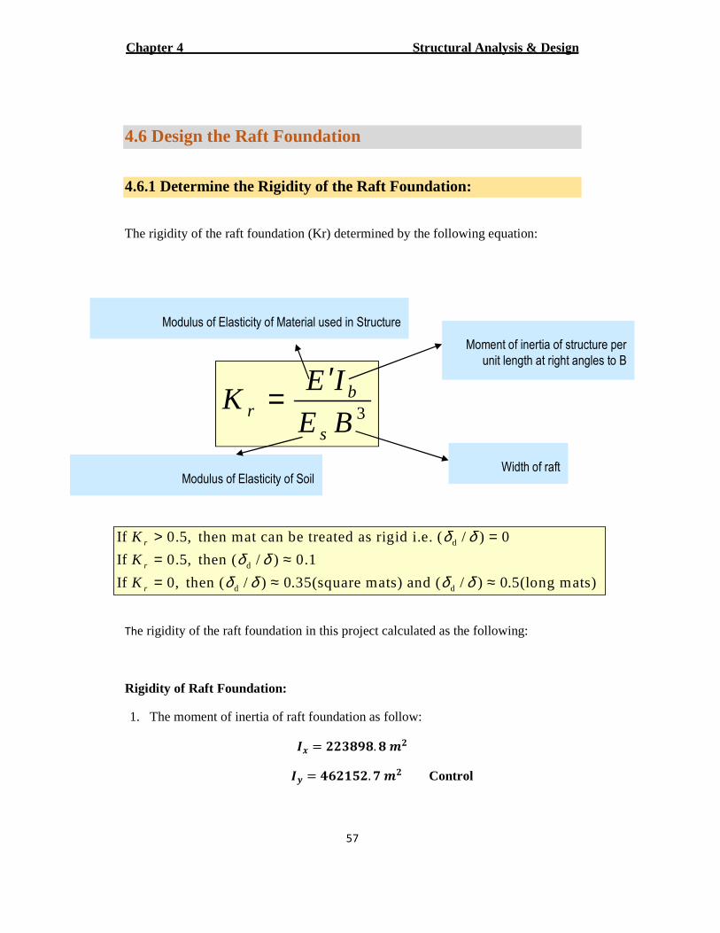
4.6 Design the Raft Foundation
4.6.1 Determine the Rigidity of the Raft Foundation:
The rigidity of the raft foundation (Kr) determined by the following equation:
The rigidity of the raft foundation in this project calculated as the following:
Rigidity of Raft Foundation:
1. The moment of inertia of raft foundation as follow:
�� = ���� �. � !�
�� = "����. � !� Control
3BE
IEK
s
br
′=
Width of raft
Moment of inertia of structure per
unit length at right angles to B
Modulus of Elasticity of Soil
Modulus of Elasticity of Material used in Structure
d
d
d d
If 0.5, then mat can be treated as rigid i.e. ( / ) 0
If 0.5, then ( / ) 0.1
If 0, then ( / ) 0.35(square mats) and ( / ) 0.5(long mats)
r
r
r
K
K
K
δ δδ δ
δ δ δ δ
> == ≈= ≈ ≈
Structural Analysis & Design Chapter 4
58
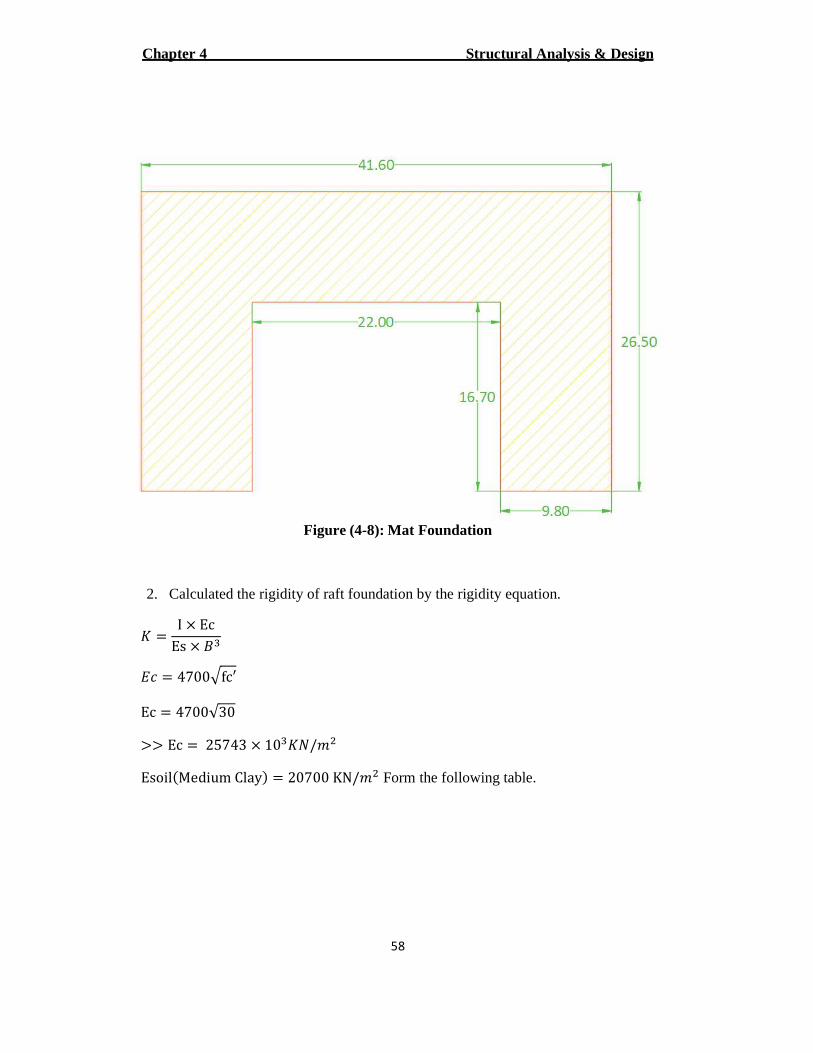
Figure (4-8): Mat Foundation
2. Calculated the rigidity of raft foundation by the rigidity equation.
# = I × EcEs × ()
*+ = 4700.fc′ Ec = 4700√30
>> Ec = 25743 × 10)#4/�6
Esoil:Medium ClayC = 20700 KN/�6 Form the following table.
Structural Analysis & Design Chapter 4
59
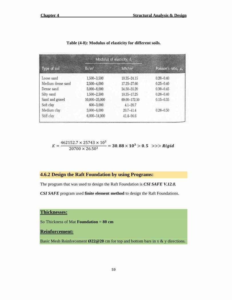
Table (4-8): Modulus of elasticity for different soils.
# = 462152.7 × 25743 × 10)20700 × 26.50) = ��. �� × ��� > �. � >>> GHIHJ
4.6.2 Design the Raft Foundation by using Programs:
The program that was used to design the Raft Foundation is CSI SAFE V.12.0.
CSI SAFE program used finite element method to design the Raft Foundations.
Thicknesses:
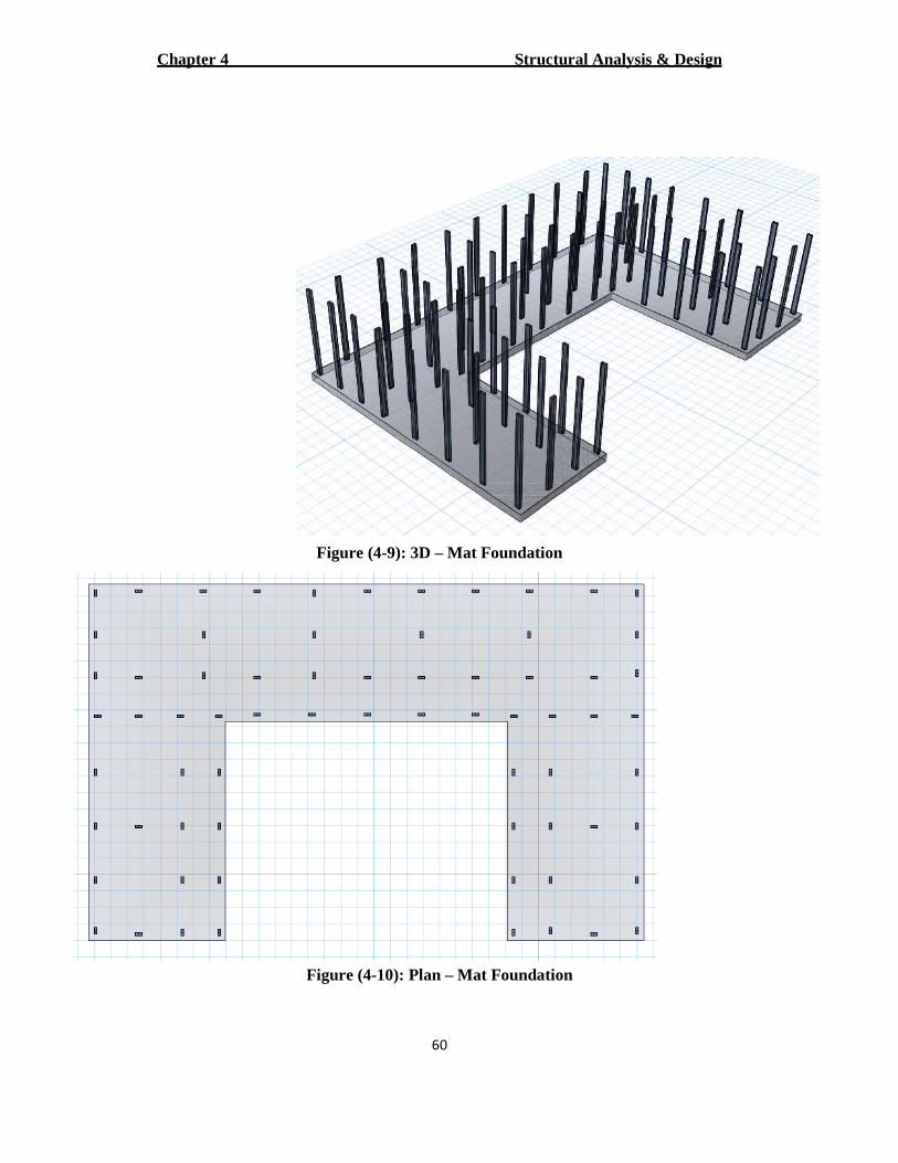
So Thickness of Mat Foundation = 80 cm
Reinforcement:
Basic Mesh Reinforcement Ø22@20 cm for top and bottom bars in x & y directions.
Structural Analysis & Design Chapter 4
60
Figure (4-9): 3D – Mat Foundation
Figure (4-10): Plan – Mat Foundation
Structural Analysis & Design Chapter 4
61
4.7 Design the Pile Foundation
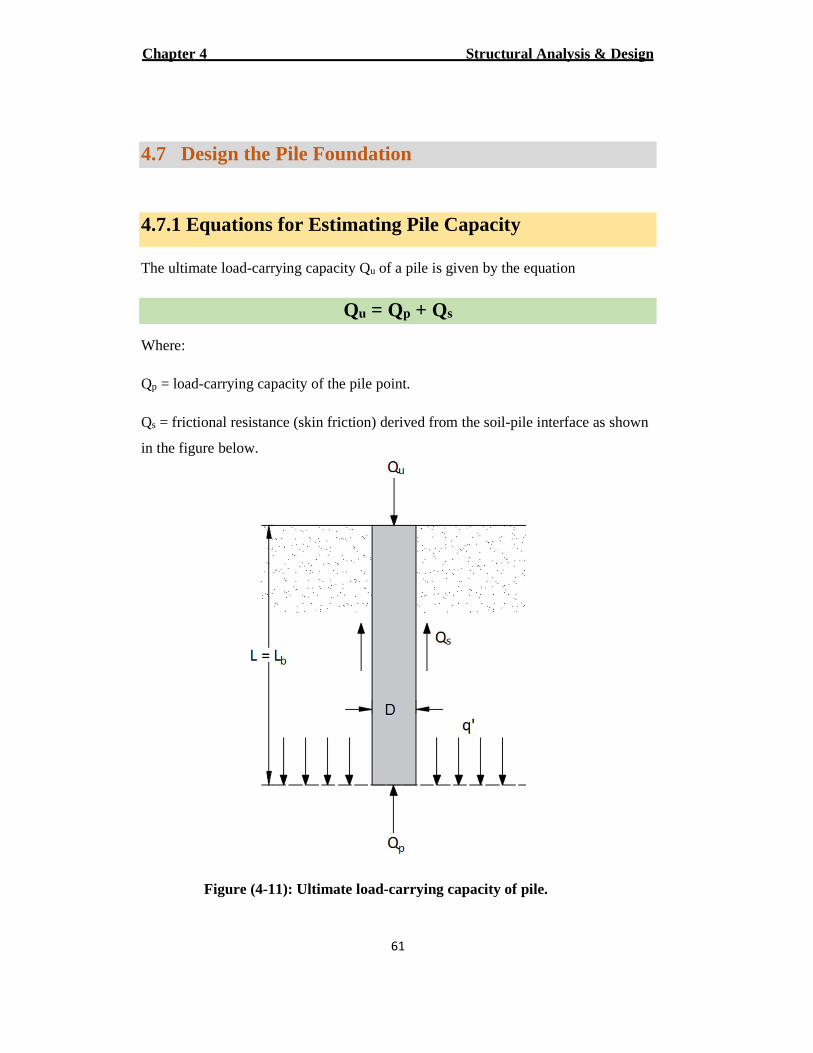
4.7.1 Equations for Estimating Pile Capacity
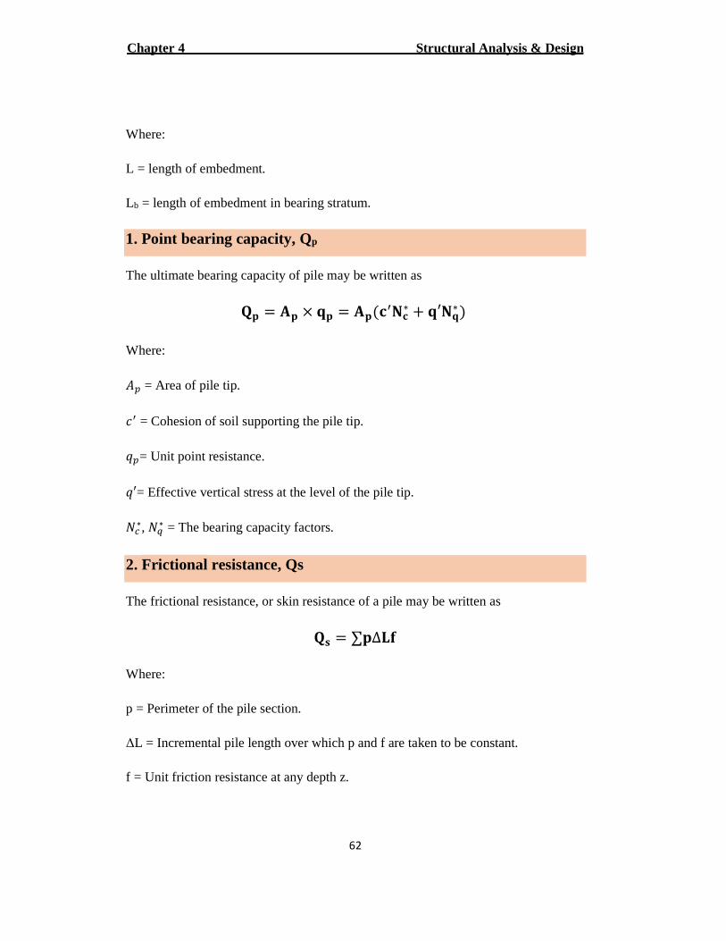
of a pile is given by the equation ucarrying capacity Q-The ultimate load
s+ Q p= Q uQ
Where:
carrying capacity of the pile point. -= load pQ
pile interface as shown -= frictional resistance (skin friction) derived from the soil sQ
in the figure below.
Figure (4-11): Ultimate load-carrying capacity of pile.
Structural Analysis & Design Chapter 4
62
Where:
L = length of embedment.
= length of embedment in bearing stratum. bL
1. Point bearing capacity, Qp
The ultimate bearing capacity of pile may be written as
KL = ML × NL = ML:O�PO∗ + N′PN∗ C Where:
ST = Area of pile tip.
+� = Cohesion of soil supporting the pile tip.
UT= Unit point resistance.
U′= Effective vertical stress at the level of the pile tip.
4V∗, 4W∗ = The bearing capacity factors.
resistance, Qs Frictional .2
The frictional resistance, or skin resistance of a pile may be written as
KX = ∑L∆[\
Where:
p = Perimeter of the pile section.
ΔL = Incremental pile length over which p and f are taken to be constant.
f = Unit friction resistance at any depth z.
Structural Analysis & Design Chapter 4
63
are discussed and calculated in sand Q pus method for method estimating QThe vario
the next several sections.
allAllowable Load, Q .3
After the total ultimate load-carrying capacity of a pile has been determined by
summing the point bearing capacity and the frictional (or skin) resistance, a reasonable
factor safety should be used to obtain the total allowable load for each pile, or
]^_`= lalQ
Where:
carrying capacity for each pile.-= Allowable load allQ
FS = Factor of safety.
, depending on the 2.5 to 4The factor of safety generally used ranges from
uncertainties surrounding the calculation of ultimate load.
A. Fractional (Skin) Resistance in Clay
Method aaaa
Is based on the assumption that the displacement of soil caused by pile driving results
in a passive lateral pressure at any depth and that the average unit skin resistance is
\bc = d:e�f + �OgC
Where: hi′j = Mean effective vertical for the embedment length.
ek′f = M� + M� + M� + ⋯[
Structural Analysis & Design Chapter 4
64
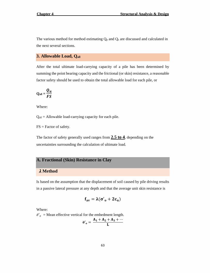
Sm, S6, S), … = Areas of the vertical effective stress diagram as shown in the figure below.
Figure (4-12): Application of a aaaa method in layered soil.
+p = Mean untrained shear strength (∅ = 0). The value of a changes with the depth of penetration of the pile. Thus, the total frictional resistance may be calculated as
KX = L[\bc
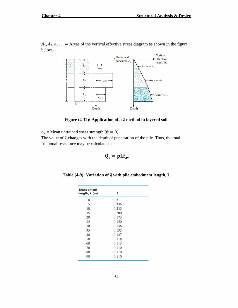
Table (4-9): Variation of aaaa with pile embedment length, L
Structural Analysis & Design Chapter 4
65
B. Fractional (Skin) Resistance in Sand
The frictional resistance calculated as
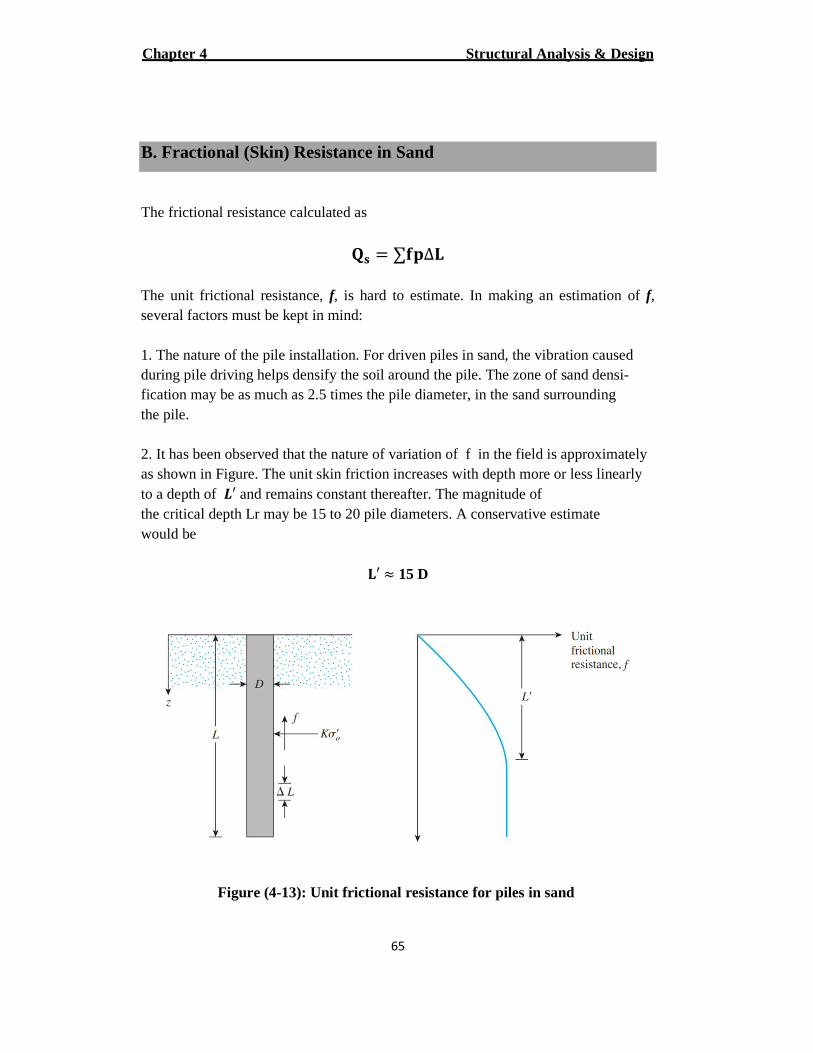
KX = ∑\L∆[ The unit frictional resistance, f, is hard to estimate. In making an estimation of f, several factors must be kept in mind: 1. The nature of the pile installation. For driven piles in sand, the vibration caused during pile driving helps densify the soil around the pile. The zone of sand densi- fication may be as much as 2.5 times the pile diameter, in the sand surrounding the pile. 2. It has been observed that the nature of variation of f in the field is approximately as shown in Figure. The unit skin friction increases with depth more or less linearly to a depth of r′ and remains constant thereafter. The magnitude of the critical depth Lr may be 15 to 20 pile diameters. A conservative estimate would be
[′ s 15 D
Figure (4-13): Unit frictional resistance for piles in sand
Structural Analysis & Design Chapter 4
66
3. At similar depths, the unit skin friction in loose sand is higher for a high-displacement pile, compared with a low-displacement pile.
4. At similar depths, bored, or jetted, piles will have a lower unit skin friction com- pared with driven piles.
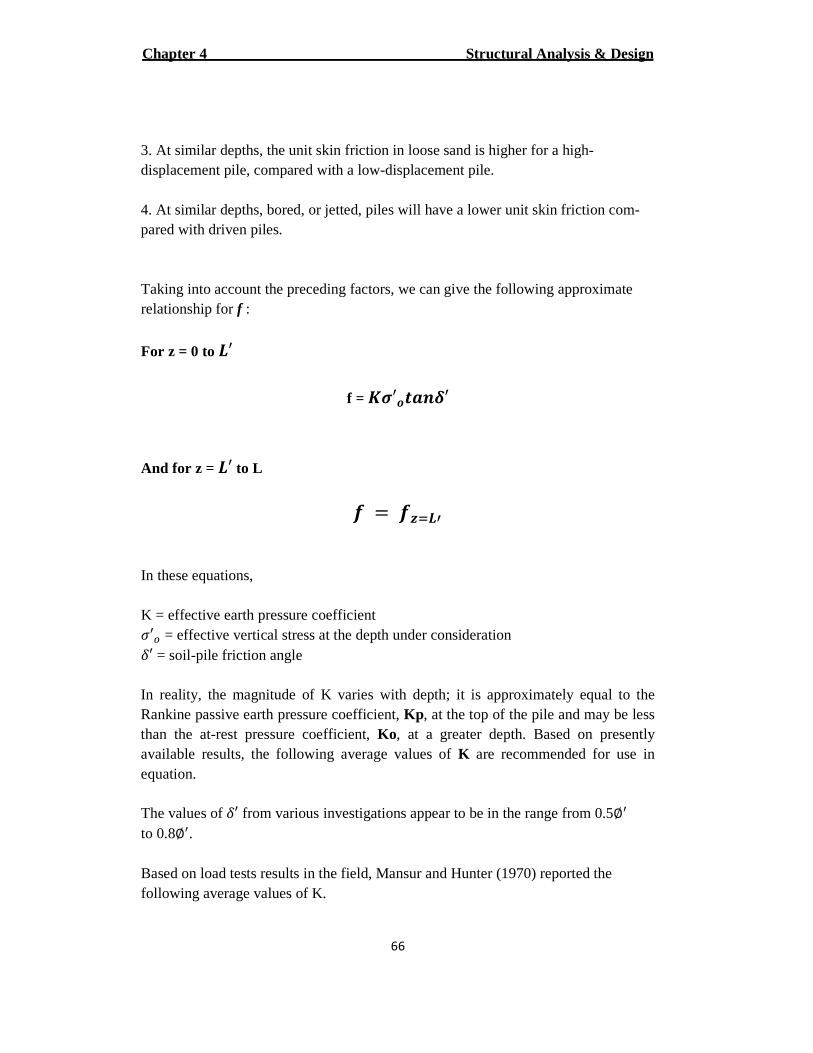
Taking into account the preceding factors, we can give the following approximate relationship for f :
For z = 0 to r′
f = tu′vwx�′
And for z = r′ to L � = �yzr� In these equations,
K = effective earth pressure coefficient h′j = effective vertical stress at the depth under consideration {′ = soil-pile friction angle
In reality, the magnitude of K varies with depth; it is approximately equal to the Rankine passive earth pressure coefficient, Kp , at the top of the pile and may be less than the at-rest pressure coefficient, Ko, at a greater depth. Based on presently available results, the following average values of K are recommended for use in equation.
The values of {′ from various investigations appear to be in the range from 0.5∅� to 0.8∅�.
Based on load tests results in the field, Mansur and Hunter (1970) reported the following average values of K.
Structural Analysis & Design Chapter 4
67
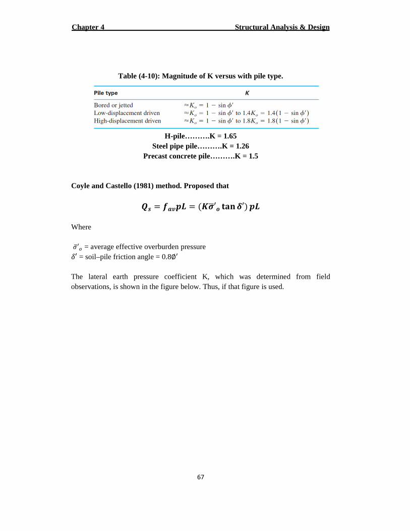
Table (4-10): Magnitude of K versus with pile type.
H-pile……….K = 1.65 Steel pipe pile……….K = 1.26
Precast concrete pile……….K = 1.5
Coyle and Castello (1981) method. Proposed that
]| = �}r = :tuk′v ~b� �′C r
Where
hi′j = average effective overburden pressure {′ = soil–pile friction angle = 0.8∅�
The lateral earth pressure coefficient K, which was determined from field observations, is shown in the figure below. Thus, if that figure is used.
Structural Analysis & Design Chapter 4
68
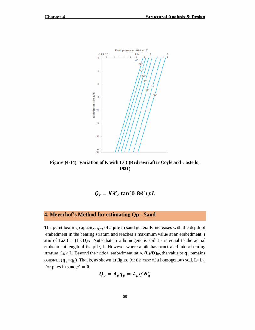
Figure (4-14): Variation of K with L/D (Redrawn aft er Coyle and Castello, 1981)
]| = tuk′v ~b�:�. �∅�C r
4. Meyerhof’s Method for estimating Qp - Sand
The point bearing capacity, UT, of a pile in sand generally increases with the depth of
embedment in the bearing stratum and reaches a maximum value at an embedment ratio of L b/D = (Lb/D)cr. Note that in a homogenous soil L b is equal to the actual embedment length of the pile, L. However where a pile has penetrated into a bearing stratum, Lb < L. Beyond the critical embedment ratio, (L b/D)cr, the value of NL remains
constant (NL=N[). That is, as shown in figure for the case of a homogenous soil, L=Lb.
For piles in sand,+� = 0.
] = �� = ��′��∗
Structural Analysis & Design Chapter 4
69
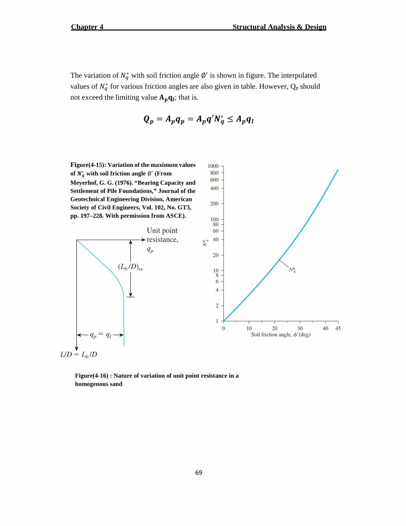
The variation of 4W∗ with soil friction angle ∅� is shown in figure. The interpolated
values of 4W∗ for various friction angles are also given in table. However, Qp should
not exceed the limiting value MLN�; that is.
] = �� = ��′��∗ � ���
Figure(4-15): Variation of the maximum values of ��∗ with soil friction angle ∅� (From
Meyerhof, G. G. (1976). “Bearing Capacity and Settlement of Pile Foundations,” Journal of the Geotechnical Engineering Division, American Society of Civil Engineers, Vol. 102, No. GT3, pp. 197–228. With permission from ASCE).
Figure(4-16) : Nature of variation of unit point resistance in a homogenous sand
Structural Analysis & Design Chapter 4
70
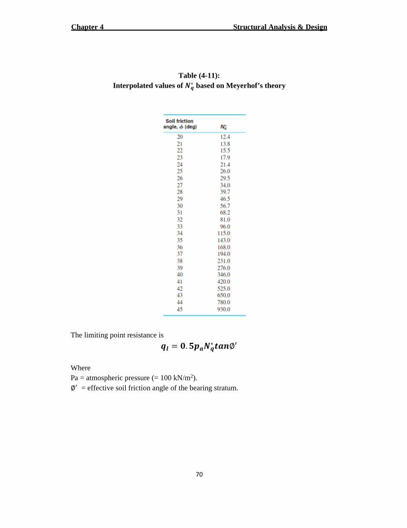
Table (4-11): Interpolated values of ��∗ based on Meyerhof’s theory
The limiting point resistance is
�� = �. ���∗ wx∅� Where
).2kN/m (= 100 pressure atmospheric = Pa ∅� = effective soil friction angle of the bearing stratum.
Structural Analysis & Design Chapter 4
71
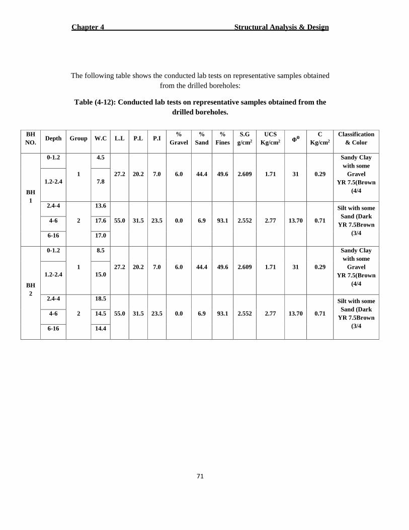
The following table shows the conducted lab tests on representative samples obtained from the drilled boreholes:
Table (4-12): Conducted lab tests on representative samples obtained from the drilled boreholes.
Classification & Color
C 2Kg/cm
oΦ
UCS 2Kg/cm
S.G 2g/cm
% Fines
% Sand
% Gravel
P.I P.L L.L W.C Group Depth BH NO.
Sandy Clay with some
Gravel (Brown7.5YR
4/4(
0.29 31 1.71 2.609 49.6 44.4 6.0 7.0 20.2 27.2
4.5
1
0-1.2
BH 1
7.8 1.2-2.4
Silt with some Sand (Dark
Brown7.5YR 3/4(
0.71 13.70 2.77 2.552 93.1 6.9 0.0 23.5 31.5 55.0
13.6
2
2.4-4
17.6 4-6
17.0 6-16
Sandy Clay with some
Gravel (Brown7.5YR
4/4(
0.29 31 1.71 2.609 49.6 44.4 6.0 7.0 20.2 27.2
8.5
1
0-1.2
BH 2
15.0 1.2-2.4
Silt with some Sand (Dark
Brown7.5YR 3/4(
0.71 13.70 2.77 2.552 93.1 6.9 0.0 23.5 31.5 55.0
18.5
2
2.4-4
14.5 4-6
14.4 6-16
Structural Analysis & Design Chapter 4
72
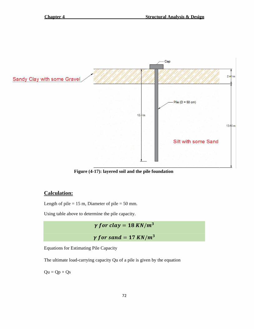
Figure (4-17): layered soil and the pile foundation
Calculation:
Length of pile = 15 m, Diameter of pile = 50 mm.
Using table above to determine the pile capacity.
� �v� ��� = �� t�/!�
� �v� |xJ = �� t�/!�
Equations for Estimating Pile Capacity
The ultimate load-carrying capacity Qu of a pile is given by the equation
Qu = Qp + Qs
Structural Analysis & Design Chapter 4
73
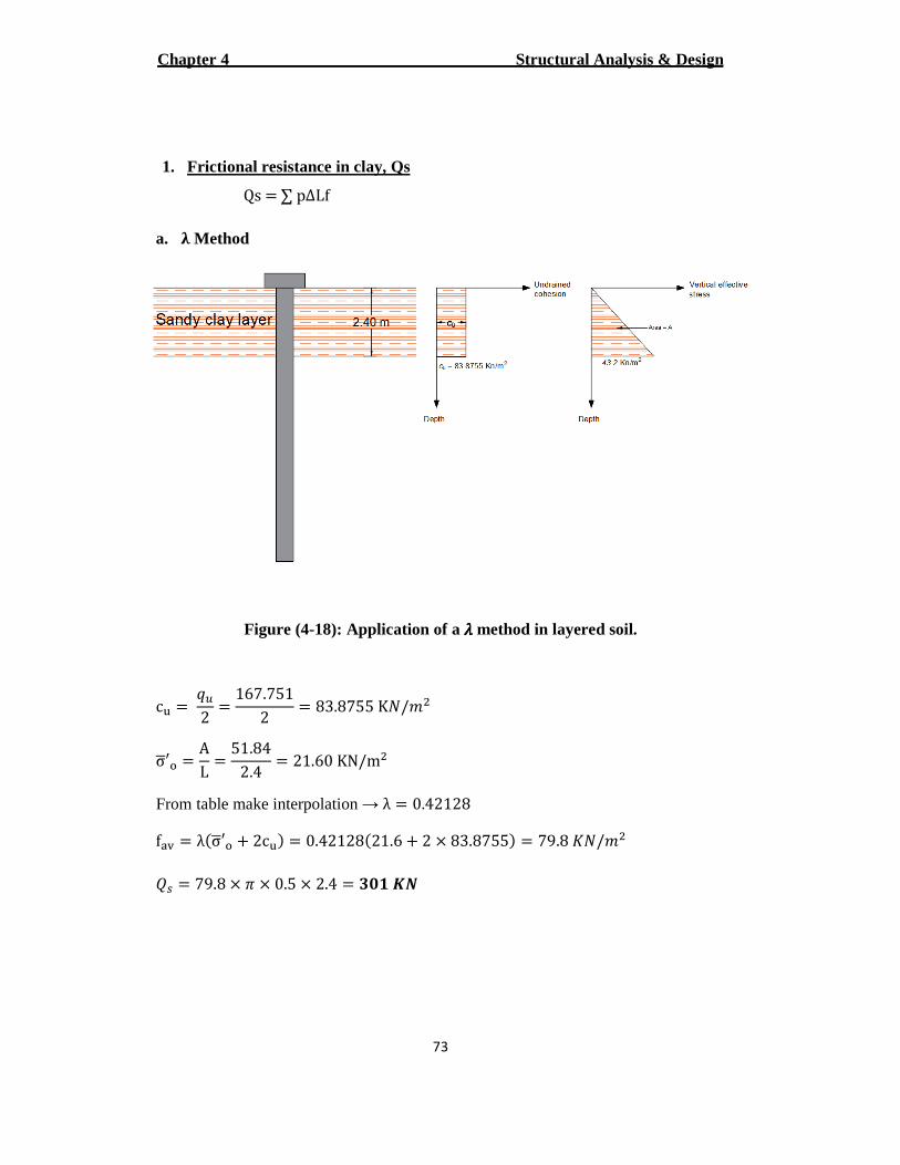
1. Frictional resistance in clay, Qs
Qs = ∑ pΔLf
a. d Method
Figure (4-18): Application of a aaaa method in layered soil.
c� = Up2 = 167.7512 = 83.8755 K4/�6
σk′� = AL = 51.84
2.4 = 21.60 KN/m6
From table make interpolation → λ = 0.42128
f�� = λ:σk′� + 2c�C = 0.42128:21.6 + 2 × 83.8755C = 79.8 #4/�6
�� = 79.8 × � × 0.5 × 2.4 = ��� t�
Structural Analysis & Design Chapter 4
74
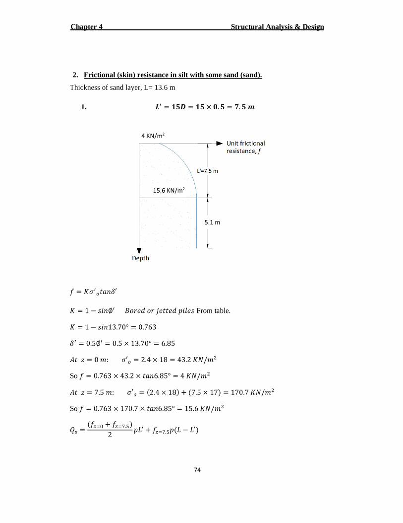
2. Frictional (skin) resistance in silt with some sand (sand).
Thickness of sand layer, L= 13.6 m
1. r� = ��� = �� × �. � = �. � !
� = #h�j���{′ # = 1 � ���∅� (�� ¡ �� ¢ �� ¡ £�¤ � From table.
# = 1 � ���13.70° = 0.763 {� = 0.5∅� = 0.5 × 13.70° = 6.85
S� ¦ = 0 �: h′j = 2.4 × 18 = 43.2 #4/�6
So � = 0.763 × 43.2 × ���6.85° = 4 #4/�6
S� ¦ = 7.5 �: h′j = :2.4 × 18C + :7.5 × 17C = 170.7 #4/�6
So � = 0.763 × 170.7 × ���6.85° = 15.6 #4/�6
�� = :� z© + � zª.«C2 £�� + � zª.«£:� � ��C
24 KN/m
5.1 m
215.6 KN/m
Structural Analysis & Design Chapter 4
75
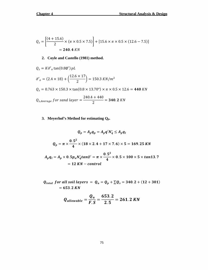
�� = ¬:4 + 15.6C2 × :� × 0.5 × 7.5C + ®15.6 × � × 0.5 × :12.6 � 7.5C¯
= � �. #4
2. Coyle and Castello (1981) method. �� = #hi′j tan:0.8∅�C £�
hi′j = :2.4 × 18C + ²12.6 × 172 ³ = 150.3 #4/�6
�� = 0.763 × 150.3 × tan:0.8 × 13.70°C × � × 0.5 × 12.6 = � #4
��,´µ¶·¸¹¶ ��� ���¡ ¤�º � = 240.4 + 4402 = � �. � #4
3. Meyerhof’s Method for estimating Qp.
] = �� = ��′��∗ � ���
] = » × �. �� × :�� × �. + �� × �. "C × � = �" . �� t�
��� = � × �. ���∗ wx∅� = » × �. �� × �. � × ��� × � × wx��. �
= �� t� � �vxw�v�
]wvw� �v� �� |vH� ��¼�| = ]^ = ] + ∑]| = � �. � + :�� + ���C= "��. � t�
]��v½��¼ = ]^_. ` = "��. ��. � = �"�. � t�
Structural Analysis & Design Chapter 4
76
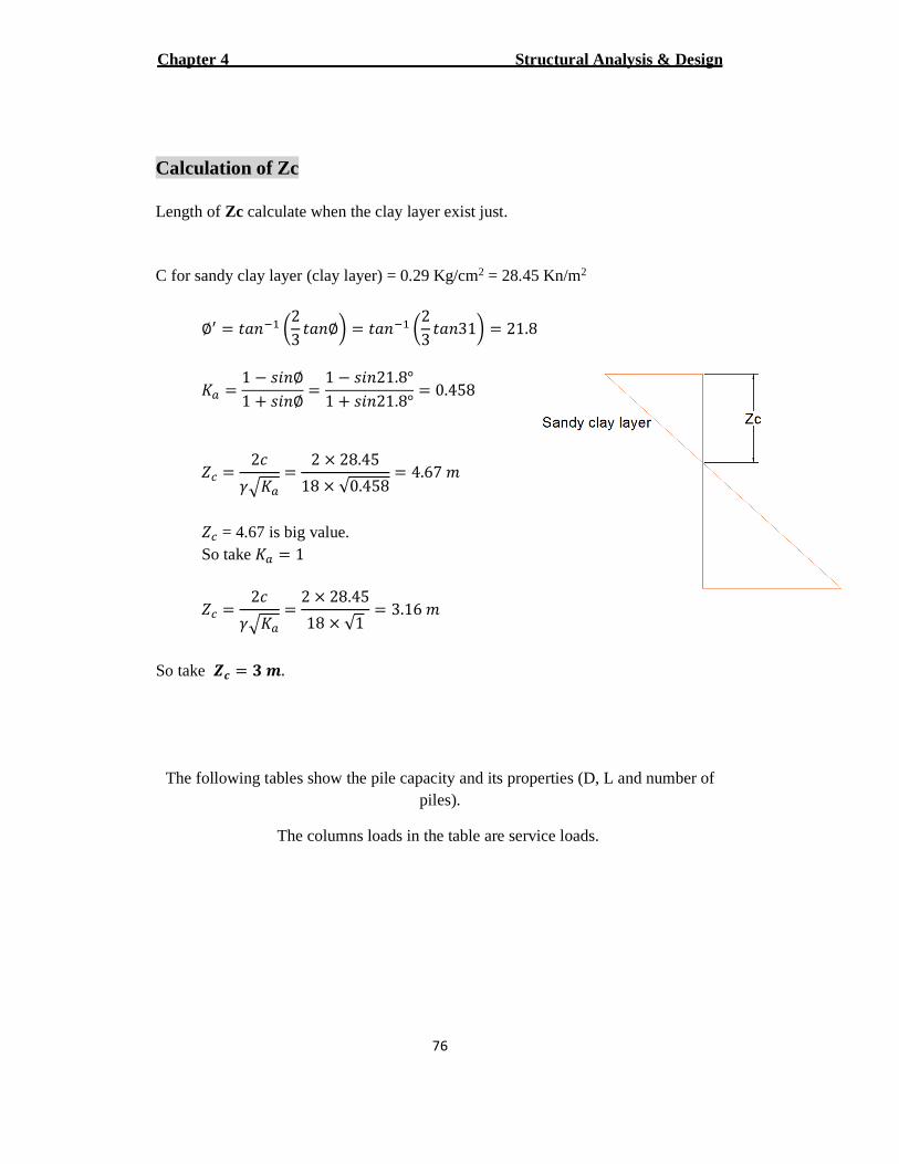
Calculation of Zc Length of Zc calculate when the clay layer exist just. C for sandy clay layer (clay layer) = 0.29 Kg/cm2 = 28.45 Kn/m2
∅� = ���¾m ²23 ���∅³ = ���¾m ²2
3 ���31³ = 21.8
#¸ = 1 � ���∅1 + ���∅ = 1 � ���21.8°
1 + ���21.8° = 0.458
¿V = 2+À.#¸
= 2 × 28.4518 × √0.458 = 4.67 �
¿V = 4.67 is big value. So take #¸ = 1
¿V = 2+À.#¸
= 2 × 28.4518 × √1 = 3.16 �
So take Á� = � !.
The following tables show the pile capacity and its properties (D, L and number of piles).
The columns loads in the table are service loads.
Structural Analysis & Design Chapter 4
77
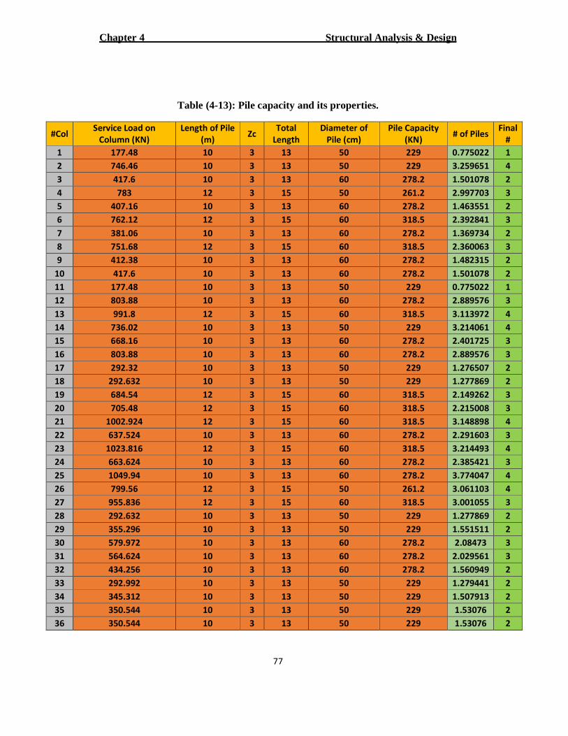
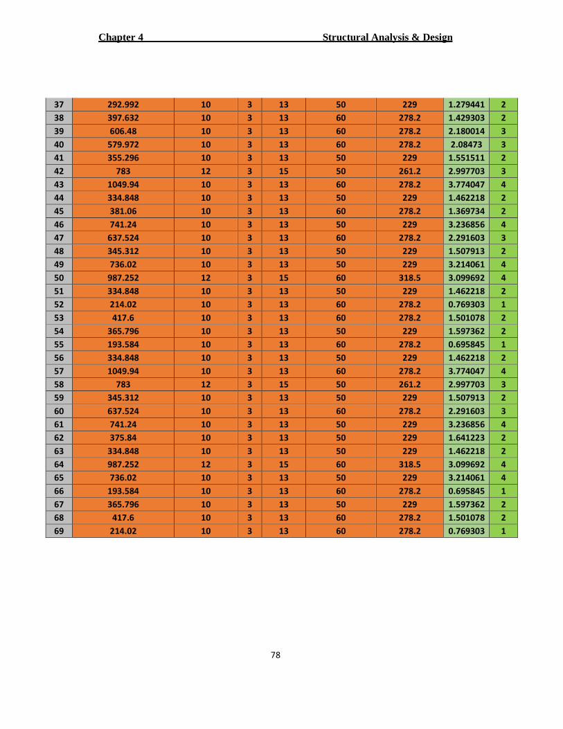
Table (4-13): Pile capacity and its properties.
#Col Service Load on
Column (KN)
Length of Pile
(m) Zc
Total
Length
Diameter of
Pile (cm)
Pile Capacity
(KN) # of Piles
Final
#
1 177.48 10 3 13 50 229 0.775022 1
2 746.46 10 3 13 50 229 3.259651 4
3 417.6 10 3 13 60 278.2 1.501078 2
4 783 12 3 15 50 261.2 2.997703 3
5 407.16 10 3 13 60 278.2 1.463551 2
6 762.12 12 3 15 60 318.5 2.392841 3
7 381.06 10 3 13 60 278.2 1.369734 2
8 751.68 12 3 15 60 318.5 2.360063 3
9 412.38 10 3 13 60 278.2 1.482315 2
10 417.6 10 3 13 60 278.2 1.501078 2
11 177.48 10 3 13 50 229 0.775022 1
12 803.88 10 3 13 60 278.2 2.889576 3
13 991.8 12 3 15 60 318.5 3.113972 4
14 736.02 10 3 13 50 229 3.214061 4
15 668.16 10 3 13 60 278.2 2.401725 3
16 803.88 10 3 13 60 278.2 2.889576 3
17 292.32 10 3 13 50 229 1.276507 2
18 292.632 10 3 13 50 229 1.277869 2
19 684.54 12 3 15 60 318.5 2.149262 3
20 705.48 12 3 15 60 318.5 2.215008 3
21 1002.924 12 3 15 60 318.5 3.148898 4
22 637.524 10 3 13 60 278.2 2.291603 3
23 1023.816 12 3 15 60 318.5 3.214493 4
24 663.624 10 3 13 60 278.2 2.385421 3
25 1049.94 10 3 13 60 278.2 3.774047 4
26 799.56 12 3 15 50 261.2 3.061103 4
27 955.836 12 3 15 60 318.5 3.001055 3
28 292.632 10 3 13 50 229 1.277869 2
29 355.296 10 3 13 50 229 1.551511 2
30 579.972 10 3 13 60 278.2 2.08473 3
31 564.624 10 3 13 60 278.2 2.029561 3
32 434.256 10 3 13 60 278.2 1.560949 2
33 292.992 10 3 13 50 229 1.279441 2
34 345.312 10 3 13 50 229 1.507913 2
35 350.544 10 3 13 50 229 1.53076 2
36 350.544 10 3 13 50 229 1.53076 2
Structural Analysis & Design Chapter 4
78
37 292.992 10 3 13 50 229 1.279441 2
38 397.632 10 3 13 60 278.2 1.429303 2
39 606.48 10 3 13 60 278.2 2.180014 3
40 579.972 10 3 13 60 278.2 2.08473 3
41 355.296 10 3 13 50 229 1.551511 2
42 783 12 3 15 50 261.2 2.997703 3
43 1049.94 10 3 13 60 278.2 3.774047 4
44 334.848 10 3 13 50 229 1.462218 2
45 381.06 10 3 13 60 278.2 1.369734 2
46 741.24 10 3 13 50 229 3.236856 4
47 637.524 10 3 13 60 278.2 2.291603 3
48 345.312 10 3 13 50 229 1.507913 2
49 736.02 10 3 13 50 229 3.214061 4
50 987.252 12 3 15 60 318.5 3.099692 4
51 334.848 10 3 13 50 229 1.462218 2
52 214.02 10 3 13 60 278.2 0.769303 1
53 417.6 10 3 13 60 278.2 1.501078 2
54 365.796 10 3 13 50 229 1.597362 2
55 193.584 10 3 13 60 278.2 0.695845 1
56 334.848 10 3 13 50 229 1.462218 2
57 1049.94 10 3 13 60 278.2 3.774047 4
58 783 12 3 15 50 261.2 2.997703 3
59 345.312 10 3 13 50 229 1.507913 2
60 637.524 10 3 13 60 278.2 2.291603 3
61 741.24 10 3 13 50 229 3.236856 4
62 375.84 10 3 13 50 229 1.641223 2
63 334.848 10 3 13 50 229 1.462218 2
64 987.252 12 3 15 60 318.5 3.099692 4
65 736.02 10 3 13 50 229 3.214061 4
66 193.584 10 3 13 60 278.2 0.695845 1
67 365.796 10 3 13 50 229 1.597362 2
68 417.6 10 3 13 60 278.2 1.501078 2
69 214.02 10 3 13 60 278.2 0.769303 1
Structural Analysis & Design Chapter 4
79
4.7.2 Pile design
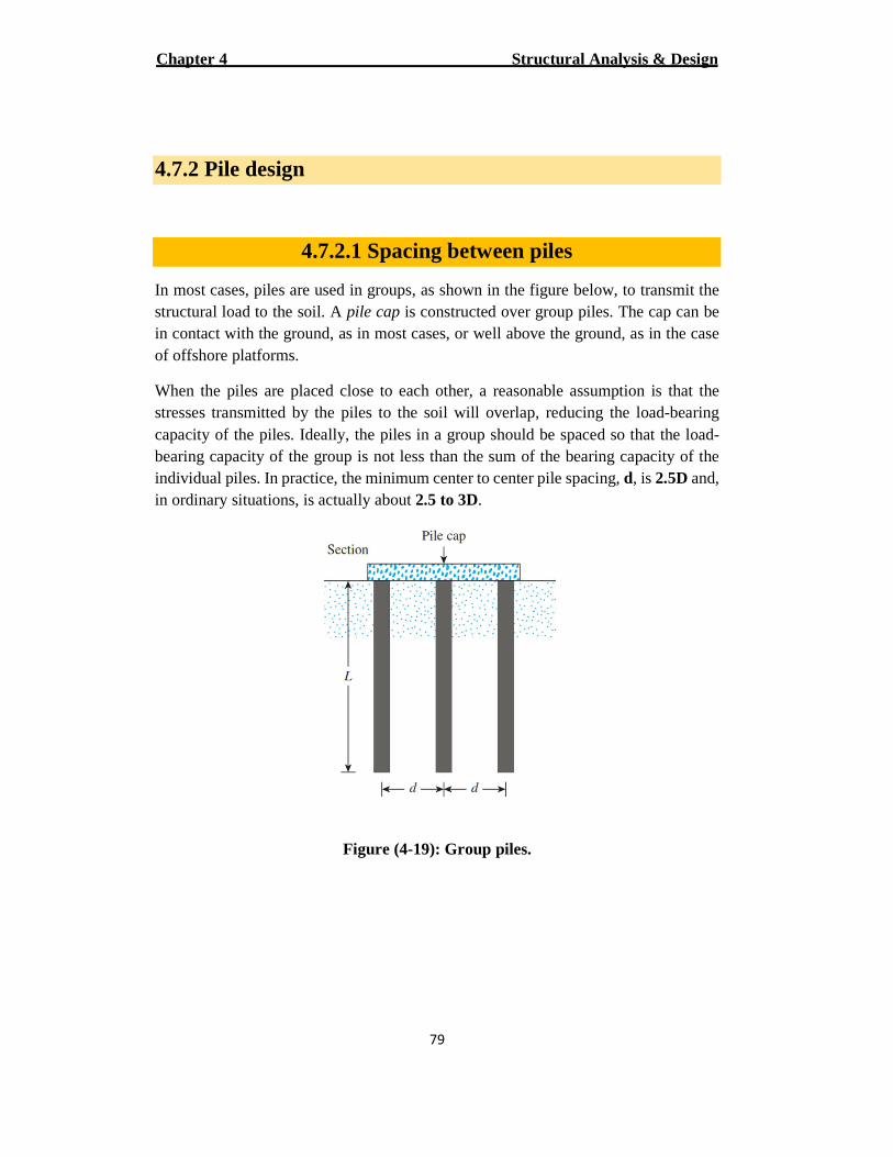
4.7.2.1 Spacing between piles
In most cases, piles are used in groups, as shown in the figure below, to transmit the structural load to the soil. A pile cap is constructed over group piles. The cap can be in contact with the ground, as in most cases, or well above the ground, as in the case of offshore platforms.
When the piles are placed close to each other, a reasonable assumption is that the stresses transmitted by the piles to the soil will overlap, reducing the load-bearing capacity of the piles. Ideally, the piles in a group should be spaced so that the load-bearing capacity of the group is not less than the sum of the bearing capacity of the individual piles. In practice, the minimum center to center pile spacing, d, is 2.5D and, in ordinary situations, is actually about 2.5 to 3D.
Figure (4-19): Group piles.
Structural Analysis & Design Chapter 4
80
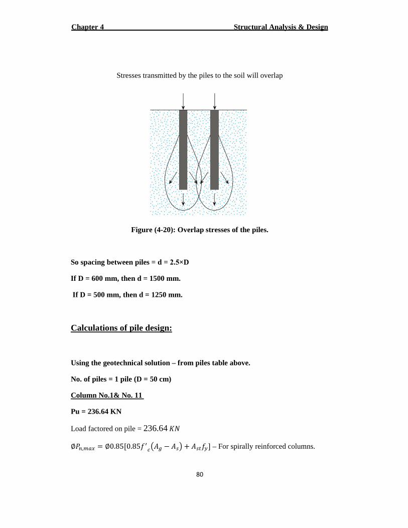
Stresses transmitted by the piles to the soil will overlap
Figure (4-20): Overlap stresses of the piles.
So spacing between piles = d = 2.5×D
If D = 600 mm, then d = 1500 mm.
If D = 500 mm, then d = 1250 mm.
Calculations of pile design:
Using the geotechnical solution – from piles table above.
No. of piles = 1 pile (D = 50 cm)
Column No.1& No. 11
Pu = 236.64 KN
Load factored on pile = 236.64 #4
∅ÂÃ,ĸŠ= ∅0.85®0.85��VÆS¹ � S�Ç + S�È�ɯ – For spirally reinforced columns.
Structural Analysis & Design Chapter 4
81
236.64 × 10) = 0.75 × 0.85®0.85 × 30:196349.54 � S�C + S�È420¯ → As < As min
0.01 < { = S�S¹ < 0.08
So use { = 0.01
As = { × S¹ = 0.01 × 196349.54 = 1963.5 ��6
Use ∅16 → 10∅16
Spacing between bars = Ì×));m©×mÎ
m© = 89 > 75 Ï#
Design of spiral reinforcement:
2= 153.94 mm s14 with a∅Use spiral
ÐVÑ = Ð � 2+�Ò � = 500 � 2 × 75 = 350 ��
S¹ = �Ð64 = � × 5006
4 = 196349.54 ��6
SVÑ = �ÐVÑ64 = � × 3506
4 = 96211.275 ��6
Ó� = 0.45 ² S¹SVÑ � 1³ ��V�ÉÈ = 0.45 ² 196349.5496211. � 1³ 30
420 = 0.03345
Ó� = 4��:ÐVÑ � ¡�C�ÐVÑ6
0.03345 = 4 × 153.94:350 � 14C� × 3506
s = 50.5 mm →
Take s = 50 mm.
Structural Analysis & Design Chapter 4
82
Check for code requirements:
1. Clear spacing between longitudinal bars:
Clear space = 89 mm.
2. Gross reinforcement ratio:
Ó¹ = 0.01
3. Number of bars: 10 > 6 – for circular members enclosed by spirals Ï#
4. Spiral diameter: ∅14 > ∅10 Ï#
5. Clear spacing for one loop: clear spacing = � � ¡� = 50 � 14 = 36 ��
25 < 36 �� < 75 Ï#
No. of piles = 4 pile (D = 60 cm)
Column No.12, No.13, No.16, No.21, No.23, No.25, No.27, No.43 No.50, No.57 & No.64
Pu = 1400 KN
Load factored on each pile = mÍ©©Í = 350 #4
∅ÂÃ,ĸŠ= ∅0.85®0.85��VÆS¹ � S�Ç + S�È�ɯ – For spirally reinforced columns.
350 × 10) = 0.75 × 0.85®0.85 × 30:282743.34 � S�C + S�È420¯ → As < As min
0.01 < { = S�S¹ < 0.08
So use { = 0.01
As = { × S¹ = 0.01 × 282743.34 = 2827.43 ��6
Structural Analysis & Design Chapter 4
83
Use∅20 → 9∅20
Spacing between bars = Ì×Í)©¾Ô×6©
Ô = 130 > 75 Ï#
Design of spiral reinforcement:
2= 153.94 mm s14 with a∅Use spiral
ÐVÑ = Ð � 2+�Ò � = 600 � 2 × 75 = 450 ��
S¹ = �Ð64 = � × 6006
4 = 282743.34 ��6
SVÑ = �ÐVÑ64 = � × 4506
4 = 159043.13 ��6
Ó� = 0.45 ² S¹SVÑ � 1³ ��V�ÉÈ = 0.45 ² 282743.34159043.13 � 1³ 30
420 = 0.025
Ó� = 4��:ÐVÑ � ¡�C�ÐVÑ6
0.025 = 4 × 153.94:450 � 14C� × 4506
s = 53 mm →
Take s = 50 mm.
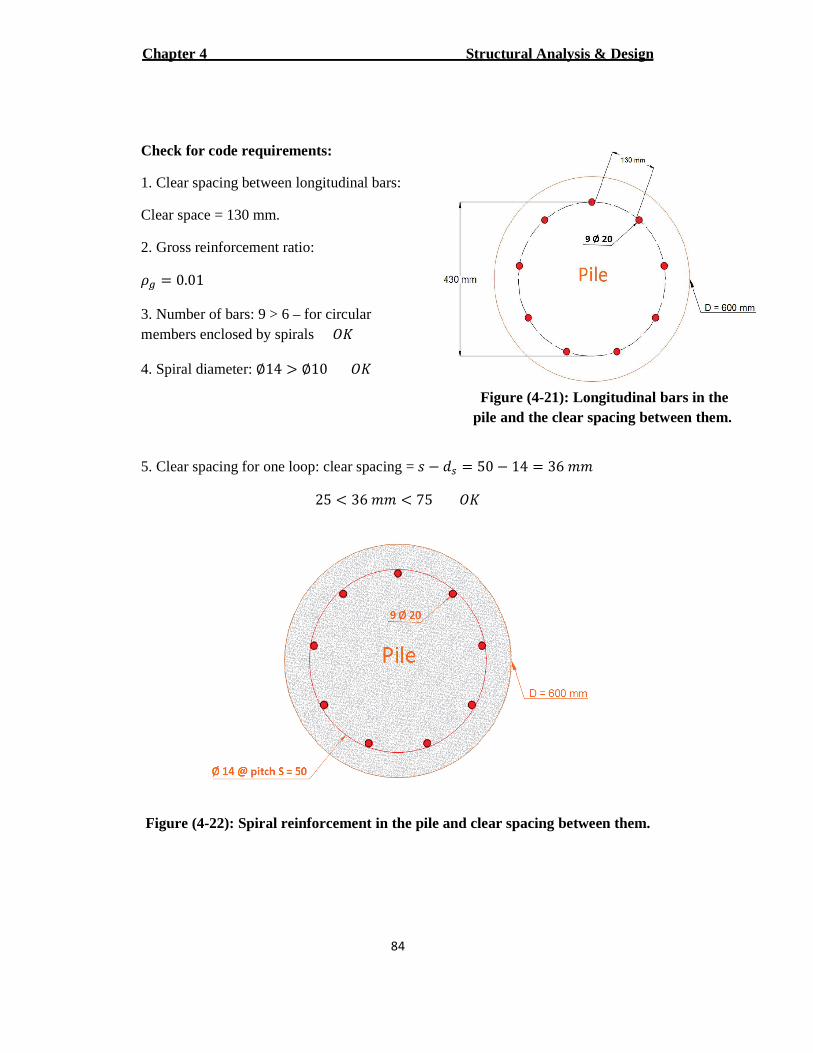
Structural Analysis & Design Chapter 4
84
Check for code requirements:
1. Clear spacing between longitudinal bars:
Clear space = 130 mm.
2. Gross reinforcement ratio:
Ó¹ = 0.01
3. Number of bars: 9 > 6 – for circular members enclosed by spirals Ï#
4. Spiral diameter: ∅14 > ∅10 Ï#
5. Clear spacing for one loop: clear spacing = � � ¡� = 50 � 14 = 36 ��
25 < 36 �� < 75 Ï#
Figure (4-22): Spiral reinforcement in the pile and clear spacing between them.
Figure (4-21): Longitudinal bars in the pile and the clear spacing between them.
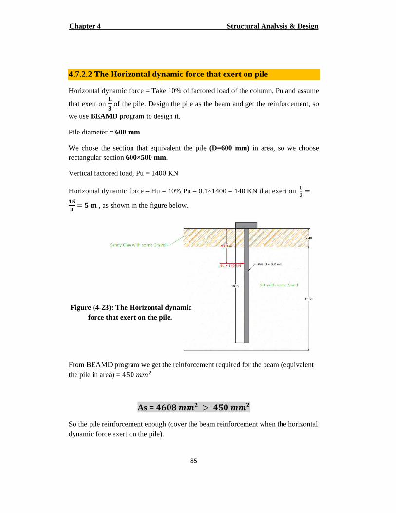
Structural Analysis & Design Chapter 4
85
4.7.2.2 The Horizontal dynamic force that exert on pile
Horizontal dynamic force = Take 10% of factored load of the column, Pu and assume
that exert on [� of the pile. Design the pile as the beam and get the reinforcement, so
we use BEAMD program to design it.
Pile diameter = 600 mm
We chose the section that equivalent the pile (D=600 mm) in area, so we choose rectangular section 600×500 mm.
Vertical factored load, Pu = 1400 KN
Horizontal dynamic force – Hu = 10% Pu = 0.1×1400 = 140 KN that exert on [� =
��� = � Õ , as shown in the figure below.
From BEAMD program we get the reinforcement required for the beam (equivalent the pile in area) = 450 ��6
"�� !!� > �� !!�As =
So the pile reinforcement enough (cover the beam reinforcement when the horizontal dynamic force exert on the pile).
Figure (4-23): The Horizontal dynamic force that exert on the pile.
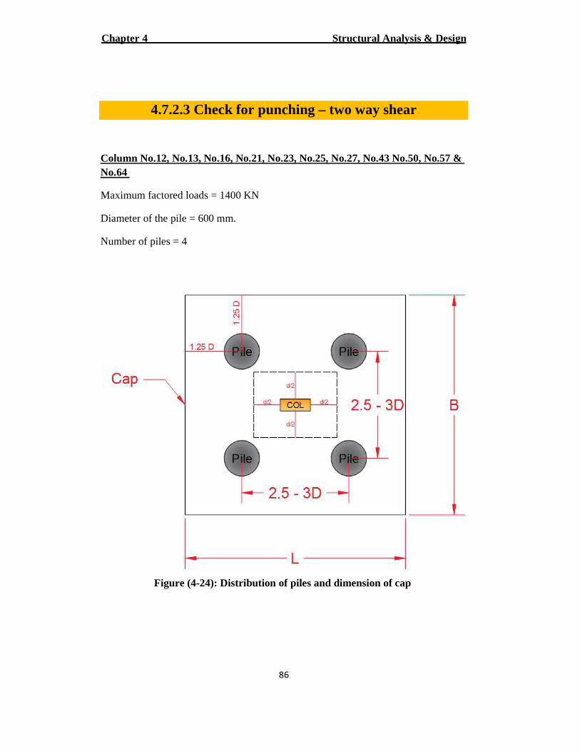
Structural Analysis & Design Chapter 4
86
4.7.2.3 Check for punching – two way shear
Column No.12, No.13, No.16, No.21, No.23, No.25, No.27, No.43 No.50, No.57 & No.64
Maximum factored loads = 1400 KN
Diameter of the pile = 600 mm.
Number of piles = 4
Figure (4-24): Distribution of piles and dimension of cap
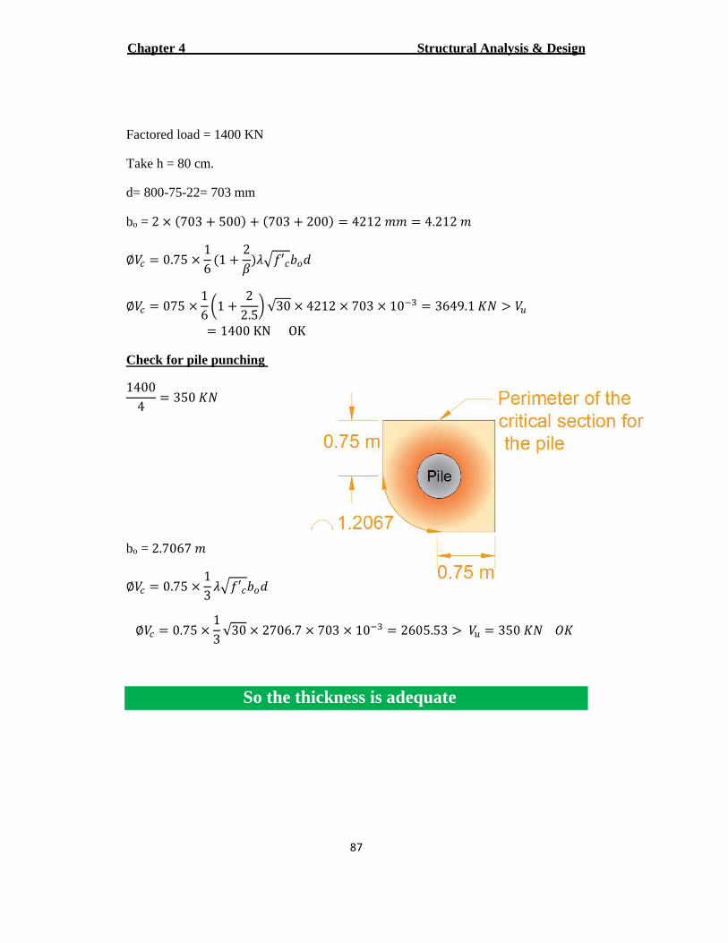
Structural Analysis & Design Chapter 4
87
Factored load = 1400 KN
Take h = 80 cm.
d= 800-75-22= 703 mm
2 × :703 + 500C + :703 + 200C = 4212 �� = 4.212 �= ob
∅ÖV = 0.75 × 16 :1 + 2
×Ca.�′VØj¡
∅ÖV = 075 × 16 ²1 + 2
2.5³ √30 × 4212 × 703 × 10¾) = 3649.1 #4 > Öp= 1400 KN OK
Check for pile punching
14004 = 350 #4
2.7067 �= ob
∅ÖV = 0.75 × 13 a.�′VØj¡
∅ÖV = 0.75 × 13 √30 × 2706.7 × 703 × 10¾) = 2605.53 > Öp = 350 #4 Ï#
So the thickness is adequate
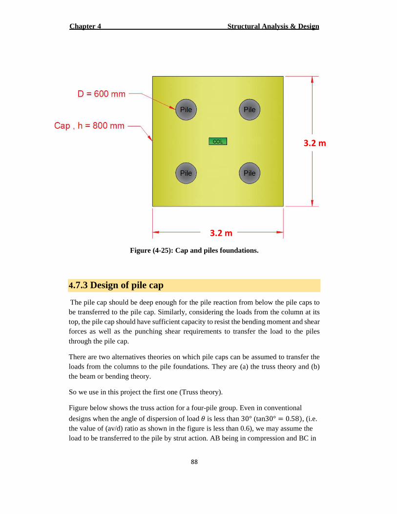
Structural Analysis & Design Chapter 4
88
Figure (4-25): Cap and piles foundations.
4.7.3 Design of pile cap
The pile cap should be deep enough for the pile reaction from below the pile caps to be transferred to the pile cap. Similarly, considering the loads from the column at its top, the pile cap should have sufficient capacity to resist the bending moment and shear forces as well as the punching shear requirements to transfer the load to the piles through the pile cap.
There are two alternatives theories on which pile caps can be assumed to transfer the loads from the columns to the pile foundations. They are (a) the truss theory and (b) the beam or bending theory.
So we use in this project the first one (Truss theory).
Figure below shows the truss action for a four-pile group. Even in conventional
designs when the angle of dispersion of load Ú is less than 30° (tan30° = 0.58C, (i.e. the value of (av/d) ratio as shown in the figure is less than 0.6), we may assume the load to be transferred to the pile by strut action. AB being in compression and BC in
3.2 m
3.2 m
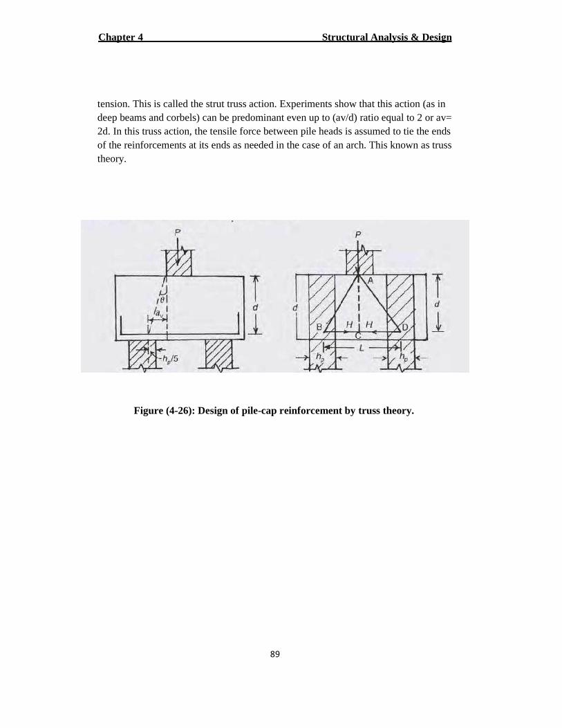
Structural Analysis & Design Chapter 4
89
tension. This is called the strut truss action. Experiments show that this action (as in deep beams and corbels) can be predominant even up to (av/d) ratio equal to 2 or av= 2d. In this truss action, the tensile force between pile heads is assumed to tie the ends of the reinforcements at its ends as needed in the case of an arch. This known as truss theory.
Figure (4-26): Design of pile-cap reinforcement by truss theory.
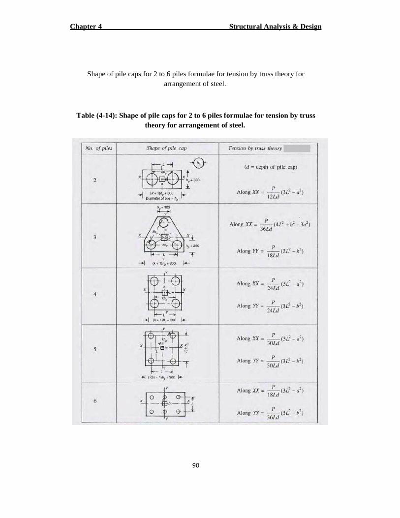
Structural Analysis & Design Chapter 4
90
Shape of pile caps for 2 to 6 piles formulae for tension by truss theory for arrangement of steel.
Table (4-14): Shape of pile caps for 2 to 6 piles formulae for tension by truss theory for arrangement of steel.
Structural Analysis & Design Chapter 4
Column No.12, No.13, No.16, No.21, No.23, No.25, No.27, No.43 No.50, No.57 & No.64
Maximum factored loads = 1400 KN
Each column has 4 piles.
Diameter of the pile = 600 mm
Cap thickness = 800 mm
Cap dimensions �. � × �. �
Spacing between piles = 2.5d mm
2.5×600 = 1500 mm
From the table:
direction-For x
Û = Â24�¡ :3�6 � �6C
Û = 140024 × 1.5 × 0.8 :3 × 1.56 � 0.56C = 316 #4
S� = Û0.87�É = 316
0.87 × 420 = 864.8 ��6
S�,ÄÜà = 0.0018Øℎ = 0.0018 × 3200 × 800 = 4608 ��6
S�,ÄÜà = 4608 ��6 > S� = 864.8 ��6 Use ∅22 → 13 ∅22
Structural Analysis & Design Chapter 4
92
direction-For y
Û = Â24�¡ :3�6 � �6C
Û = 140024 × 1.5 × 0.8 :3 × 1.56 � 0.26C = 326.2 #4
S� = Û0.87�É = 326.2
0.87 × 420 = 892.7 ��6
S�,ÄÜà = 0.0018Øℎ = 0.0018 × 3200 × 800 = 4608 ��6
S�,ÄÜà = 4608 ��6 > S� = 892.7 ��6 Use ∅22 → 13 ∅22
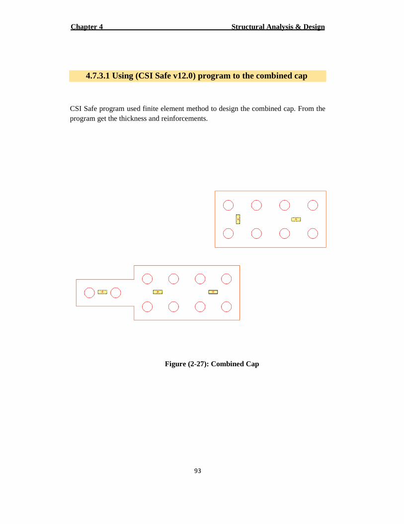
Structural Analysis & Design Chapter 4
93
4.7.3.1 Using (CSI Safe v12.0) program to the combined cap
CSI Safe program used finite element method to design the combined cap. From the program get the thickness and reinforcements.
Figure (2-27): Combined Cap
الفصل الخامـس النتائـج والتوصـیات
الخامــسالفصــــــــــــــل
النتائــج والتوصـــیات
5
النتائــج 1.5
التوصــیات 2.5
المصادر والمراجـع 3.5
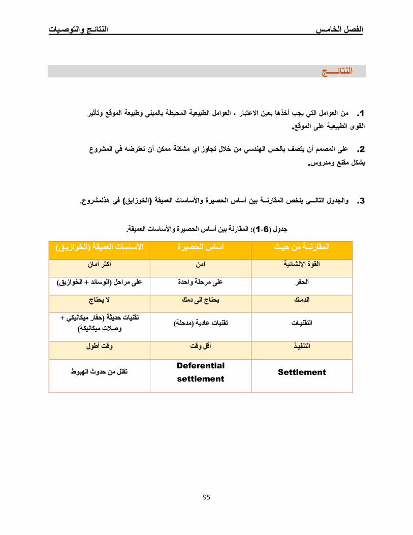
الفصل الخامـس النتائـج والتوصـیات
95
النتائــــج
ائج :
1. من العوامل التي یجب أخذھا بعین االعتبار ، العوامل الطبیعیة المحیطة بالمبنى وطبیعة الموقع وتأثیر
القوى الطبیعیة على الموقع.
عو 2. على المصمم أن یتصف بالحس الھندسي من خالل تجاوز اي مشكلة ممكن أن تعترضھ في المشر
بشكل مقنع ومدروس.
3. والجدول التالـــي یلخص المقارنــة بین أساس الحصیرة واألساسات العمیقة (الخوزایق) في ھذلمشروع.
): المقارنة بین أساس الحصیرة واألساسات العمیقة.1-6جدول (
المقارنــة من حیـث أساس الحصیرة األساسات العمیقة (الخوازیـق)
ناأكثر آم القوة اإلنشائیة آمن
(الوسائد + الخوازیق) على مراحل الحفر على مرحلة واحدة
الدمـك یحتاج الى دمك ال یحتاج
+ تقنیات حدیثة (حفار میكانیكي وصالت میكانیكة)
التقنیـات تقنیات عادیة (مدحلة)
التنفیـذ أقل وقت وقت أطول
من حدوث الھبوط للتق Deferential
settlement Settlement

الفصل الخامـس النتائـج والتوصـیات
96
التوصــیات
في ھذه الحالة Mat Foundation بناءا على ما ورد من نتائج وتحلیل یوصي فریق العمل باستخدام أساس الحصیرة
Pile في ھذا المشروع ، اذ تبین ان أساس الحصیرة أقل تكلفة وأكثر اقتصادیـة وأسھل للتنفیذ من األساسات العمیقة
Foundation
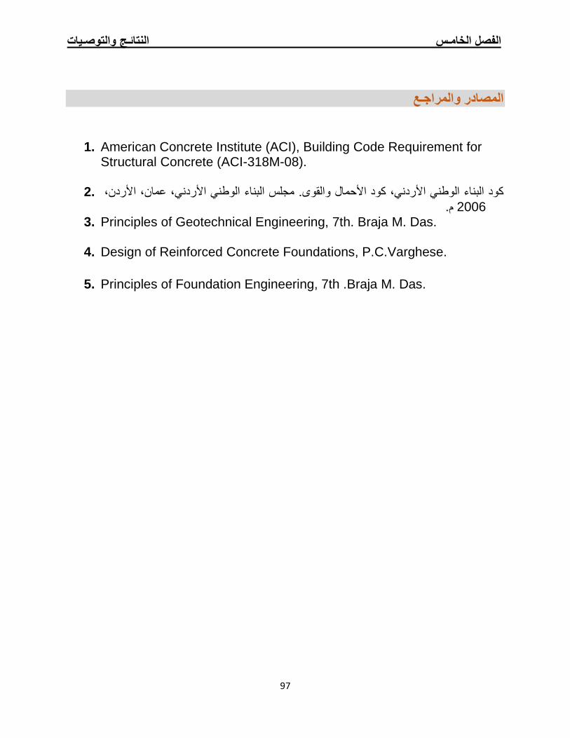
الفصل الخامـس النتائـج والتوصـیات
97
والمراجـعالمصادر
1. American Concrete Institute (ACI), Building Code Requirement for Structural Concrete (ACI-318M-08).
كود البناء الوطني األردني، كود األحمال والقوى. مجلس البناء الوطني األردني، عمان، األردن، .2
م. 2006 3. Principles of Geotechnical Engineering, 7th. Braja M. Das.
4. Design of Reinforced Concrete Foundations, P.C.Varghese.
5. Principles of Foundation Engineering, 7th .Braja M. Das.

هللا " ـد ـم ـح ب م ـــ" ت
Related Documents


![Form-SA-PPU [Compatibility Mode]](https://static.cupdf.com/doc/110x72/58676e531a28abde3f8ba5c9/form-sa-ppu-compatibility-mode.jpg)