DETERMINING LIQUID LIMITS OF SOILS TXDOT DESIGNATION: TEX-104-E CONSTRUCTION DIVISION 1 – 12 LAST REVIEWED: SEPTEMBER 2014 Test Procedure for DETERMINING LIQUID LIMITS OF SOILS TxDOT Designation: Tex-104-E Effective Date: August 1999 1. SCOPE 1.1 This procedure determines the liquid limit of soils, defined as the water content of a soil at the arbitrarily determined boundary between the liquid and plastic states, expressed as a percentage of the oven-dried mass of the soil. 1.2 The values given in parentheses (if provided) are not standard and may not be exact mathematical conversions. Use each system of units separately. Combining values from the two systems may result in nonconformance with the standard. 2. APPARATUS 2.1 Mixing dish, porcelain, 102–127 mm (4–5 in.) in diameter. 2.2 Spatula, flexible, with blade approximately 102 mm (4 in.) long and 19 mm (0.75 in.) wide. 2.3 Balance, Class G1 in accordance with Tex-901-K, minimum capacity of 100 g. 2.4 Drying oven, vented, maintained at 110 ± 5°C (230 ± 9°F). 2.5 Weighing dishes, non-absorbent, with lids. 2.6 Grooving tool, dimensions shown in Figure 1, made of non-absorbent, non-reactive material. (This grooving tool may be used in combination with the grooving tool specified by AASHTO T 89.) 2.7 Liquid limit device, consisting of a brass cup having a weight including cup hanger of 185–215 g and carriage conforming to the dimensions shown in Figure 4. Note 1—Wear is excessive when the point of contact on the cup or base exceeds 13 mm (0.5 in.) in diameter, or when any point on the rim of the cup is worn to half of the original thickness. Replace the cup when the groove-wear in the cup is 0.1 mm (0.004 in.) Refinish a base that is excessively worn, as long as the thickness meets the tolerance specified in Figure 4. 2.8 Height-of-drop metal gauge block, 10 mm (0.4 in.) thick and approximately 51 mm (2 in.) long and 25 mm (1 in.) wide.

Welcome message from author
This document is posted to help you gain knowledge. Please leave a comment to let me know what you think about it! Share it to your friends and learn new things together.
Transcript
DETERMINING LIQUID LIMITS OF SOILS TXDOT DESIGNATION: TEX-104-E
CONSTRUCTION DIVISION 1 – 12 LAST REVIEWED: SEPTEMBER 2014
Test Procedure for
DETERMINING LIQUID LIMITS OF SOILS
TxDOT Designation: Tex-104-E
Effective Date: August 1999
1. SCOPE
1.1 This procedure determines the liquid limit of soils, defined as the water content of a soil at the arbitrarily determined boundary between the liquid and plastic states, expressed as a percentage of the oven-dried mass of the soil.
1.2 The values given in parentheses (if provided) are not standard and may not be exact mathematical conversions. Use each system of units separately. Combining values from the two systems may result in nonconformance with the standard.
2. APPARATUS
2.1 Mixing dish, porcelain, 102–127 mm (4–5 in.) in diameter.
2.2 Spatula, flexible, with blade approximately 102 mm (4 in.) long and 19 mm (0.75 in.) wide.
2.3 Balance, Class G1 in accordance with Tex-901-K, minimum capacity of 100 g.
2.4 Drying oven, vented, maintained at 110 ± 5°C (230 ± 9°F).
2.5 Weighing dishes, non-absorbent, with lids.
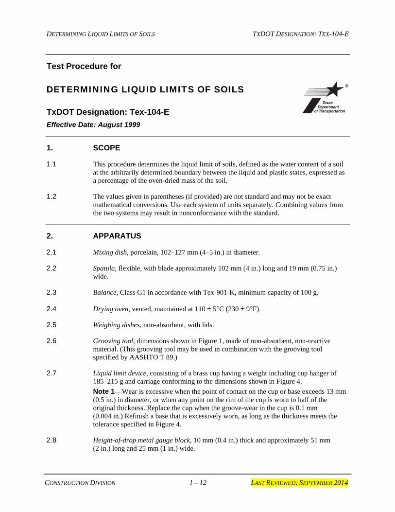
2.6 Grooving tool, dimensions shown in Figure 1, made of non-absorbent, non-reactive material. (This grooving tool may be used in combination with the grooving tool specified by AASHTO T 89.)
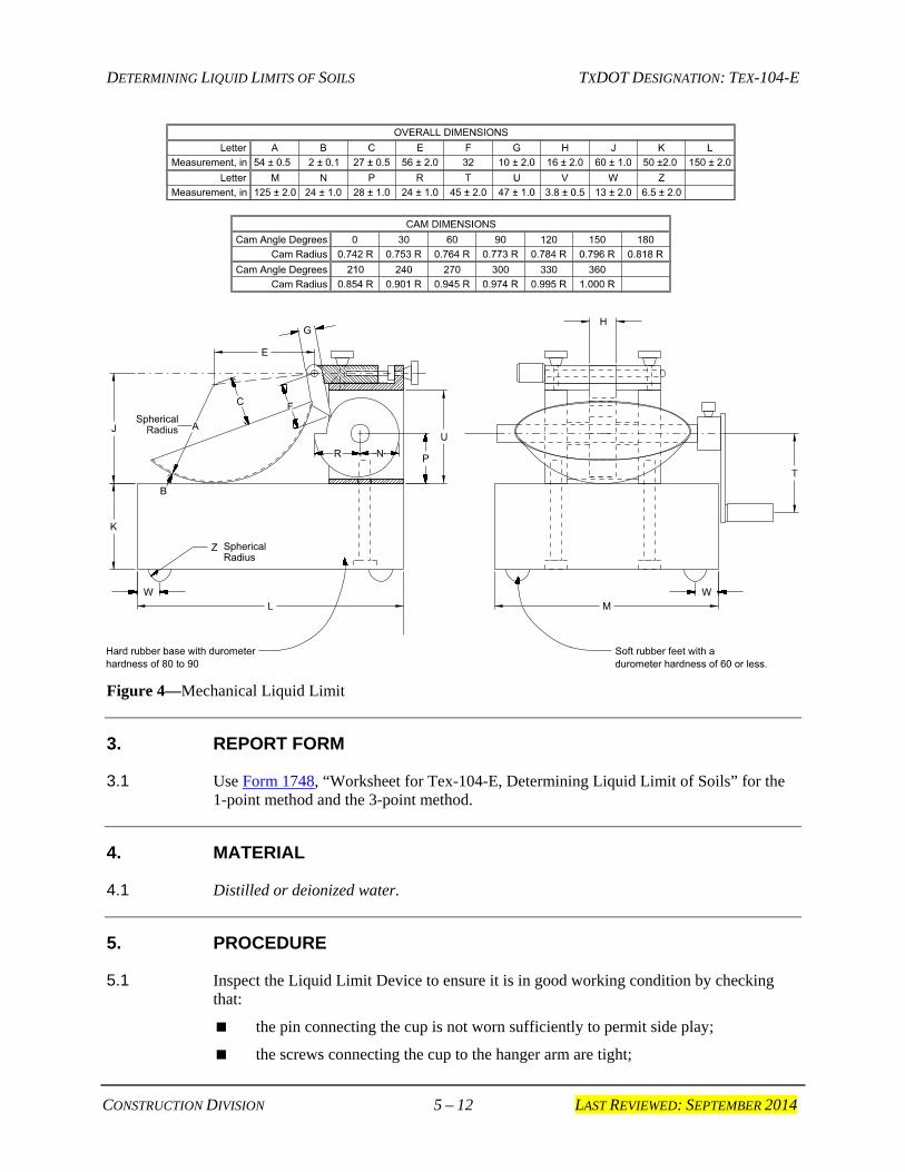
2.7 Liquid limit device, consisting of a brass cup having a weight including cup hanger of 185–215 g and carriage conforming to the dimensions shown in Figure 4.
Note 1—Wear is excessive when the point of contact on the cup or base exceeds 13 mm (0.5 in.) in diameter, or when any point on the rim of the cup is worn to half of the original thickness. Replace the cup when the groove-wear in the cup is 0.1 mm (0.004 in.) Refinish a base that is excessively worn, as long as the thickness meets the tolerance specified in Figure 4.
2.8 Height-of-drop metal gauge block, 10 mm (0.4 in.) thick and approximately 51 mm (2 in.) long and 25 mm (1 in.) wide.
DETERMINING LIQUID LIMITS OF SOILS TXDOT DESIGNATION: TEX-104-E
CONSTRUCTION DIVISION 2 – 12 LAST REVIEWED: SEPTEMBER 2014
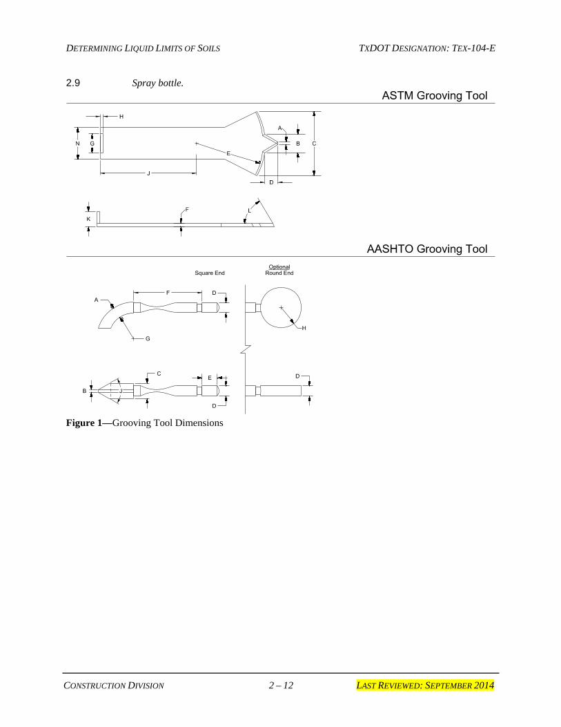
2.9 Spray bottle.
Figure 1—Grooving Tool Dimensions
DETERMINING LIQUID LIMITS OF SOILS TXDOT DESIGNATION: TEX-104-E
CONSTRUCTION DIVISION 3 – 12 LAST REVIEWED: SEPTEMBER 2014
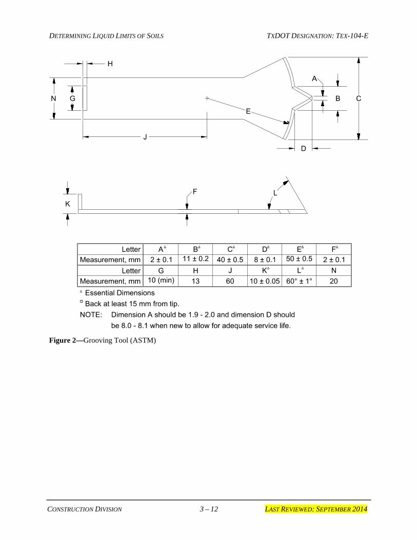
Figure 2—Grooving Tool (ASTM)
DETERMINING LIQUID LIMITS OF SOILS TXDOT DESIGNATION: TEX-104-E
CONSTRUCTION DIVISION 4 – 12 LAST REVIEWED: SEPTEMBER 2014
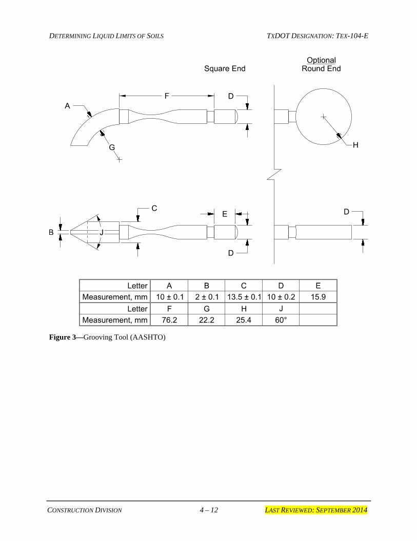
Figure 3—Grooving Tool (AASHTO)
DETERMINING LIQUID LIMITS OF SOILS TXDOT DESIGNATION: TEX-104-E
CONSTRUCTION DIVISION 5 – 12 LAST REVIEWED: SEPTEMBER 2014
Figure 4—Mechanical Liquid Limit
3. REPORT FORM
3.1 Use Form 1748, “Worksheet for Tex-104-E, Determining Liquid Limit of Soils” for the 1-point method and the 3-point method.
4. MATERIAL
4.1 Distilled or deionized water.
5. PROCEDURE
5.1 Inspect the Liquid Limit Device to ensure it is in good working condition by checking that:
the pin connecting the cup is not worn sufficiently to permit side play;
the screws connecting the cup to the hanger arm are tight;
DETERMINING LIQUID LIMITS OF SOILS TXDOT DESIGNATION: TEX-104-E
CONSTRUCTION DIVISION 6 – 12 LAST REVIEWED: SEPTEMBER 2014
the points of contact on the cup and base are not excessively worn; and
a groove has not been worn into the cup from long usage.
5.2 Inspect the grooving tool and the liquid limit device frequently to ensure that the critical dimensions meet those shown in Figure 1 and Figure 4, respectively.
5.3 Use the height-of-drop gauge block and the adjustment plate (H, shown in Figure 4) to adjust the height of the cup.
5.4 Secure the adjustment plate by tightening the screws.
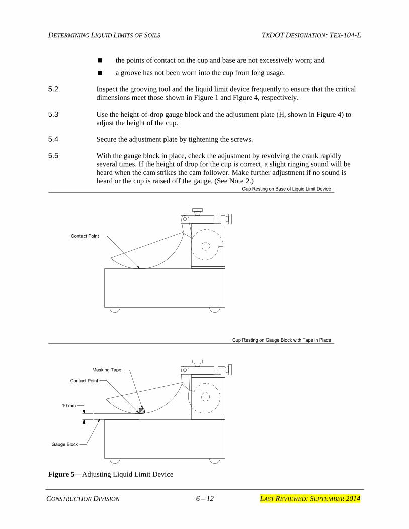
5.5 With the gauge block in place, check the adjustment by revolving the crank rapidly several times. If the height of drop for the cup is correct, a slight ringing sound will be heard when the cam strikes the cam follower. Make further adjustment if no sound is heard or the cup is raised off the gauge. (See Note 2.)
Figure 5—Adjusting Liquid Limit Device
DETERMINING LIQUID LIMITS OF SOILS TXDOT DESIGNATION: TEX-104-E
CONSTRUCTION DIVISION 7 – 12 LAST REVIEWED: SEPTEMBER 2014
Note 2—A convenient procedure for adjusting the height of drop is as follows:
Place a piece of masking tape across the outside bottom of the cup parallel with the axis of the cup hanger pivot.
The edge of the tape away from the cup hanger should bisect the spot on the cup that contacts the base.
For new cups, placing a piece of carbon paper on the base and allowing the cup to drop several times will mark the contact spot.
Attach the cup to the device and turn the crank until the cup is raised to its maximum height.
Slide the height gauge under the cup from the front, and observe whether the gauge contacts the cup or the tape. See Figure 4 for a side view.
If the tape and cup are both contacted, the height of drop is approximately correct. If not, adjust the cup until simultaneous contact is made.
Check adjustment by turning the crank at two revolutions per second while holding the gauge in position against the tape and cup.
If a ringing or clicking sound is heard without the cup rising from the gauge, the adjustment is correct.
If no ringing is heard, or if the cup rises from the gauge, readjust the height of drop.
If the cup rocks on the gauge during this checking operation, the cam follower pivot is excessively worn, and the worn parts should be replaced.
Always remove the tape after completion of the adjustment operation.
6. PREPARING SAMPLE
6.1 Prepare the soil binder in accordance with Tex-101-E, “Dry Preparation (Method A) or “Wet Preparation (Method B).” Prepare a referee sample according to Method A only.
PART I, MULTI-POINT METHOD
7. SCOPE
7.1 Use the multi-point method (Part I) as a referee method. The results of this method overrule the results of the one-point method (Part II) in cases of dispute.
8. PROCEDURE
Note 3—Go immediately to Section 8.6. if Tex-101-E, Method B was used to prepare the dry soil sample.
DETERMINING LIQUID LIMITS OF SOILS TXDOT DESIGNATION: TEX-104-E
CONSTRUCTION DIVISION 8 – 12 LAST REVIEWED: SEPTEMBER 2014
8.1 Place approximately 100 g of the soil sample in the mixing dish.
8.2 Thoroughly mix the soil with small increments of distilled or deionized water. Use a spray bottle to apply a uniform mist of water to the sample.
8.3 Alternately stir, knead, and chop the sample with a spatula, thoroughly mixing each increment of water with the soil before adding another increment of water.
Note 4—Do not use the cup of the liquid limit device for mixing the soil and water.
8.4 Add water and mix thoroughly until the soil-water mixture produces a groove closure with 25 to 35 blows by following Sections 8.7 through 8.14.
8.5 Cover the mixing dish and allow the sample to stand for at least 12 hours.
Note 5—Some soils are slow to absorb water; therefore, it is possible to add increments of water so fast that a false liquid limit is obtained. Avoid this by allowing more mixing and/or time for soil to absorb moisture sufficiently. If more soil is added to dry out the sample, mix thoroughly and allow ample time for the soil to absorb moisturesufficiently. Judgment may be used to shorten the soaking time for low Plasticity Index (PI) materials. All referee samples will be soaked for the full term.
8.6 Place a sufficient quantity of thoroughly mixed material in the cup of the liquid limit device and above the spot where the cup rests on the base.
8.7 Squeeze and spread the soil-water mixture with the spatula to level and at the same time trim to a depth of about 10 mm (0.4 in.) at the point of maximum thickness.
8.8 Use as few strokes of the spatula as possible, being careful not to entrap air bubbles within the mass. Return the excess soil to the mixing dish.
8.9 Divide the soil in the cup by a firm stroke of the grooving tool along the diameter through the centerline of the cam follower, so a clean sharp groove of the proper dimensions is formed. The grooving tool should be drawn in an arc and perpendicular to the surface of the cup through its movement.
8.10 To avoid tearing the sides of the groove or slipping of the soil pat in the cup, use no more than six strokes.
8.11 The depth of the groove should be increased with each stroke and only the last stroke should scrape the bottom of the cup.
8.12 When using the AASHTO grooving tool, the depth of the groove should be measured to assure a groove depth of 8 ± 0.1 mm (0.3 ± 0.05 in.)
8.13 Lift and drop the cup by turning the crank at the approximate rate of two revolutions per second until the two halves of the soil pat come in contact at the bottom of the groove for a distance of about 13 mm (0.5 in.)
8.14 Record the number of blows required to close the groove. Observe at least two groove closures before one is accepted for the record.
DETERMINING LIQUID LIMITS OF SOILS TXDOT DESIGNATION: TEX-104-E
CONSTRUCTION DIVISION 9 – 12 LAST REVIEWED: SEPTEMBER 2014
Note 6— Do not hold the base of the machine while the crank is being turned. Some soils tend to slide on the surface of the cup instead of flowing. If this occurs, remove the sample from the cup and place in the mixing bowl, then add more water to the sample and remix. Place the soil-water mixture in the cup. Spread and smooth the soil with the spatula. Cut a groove with the grooving tool, and repeat the above step. If the soil continues to slide on the cup with 20 blows or fewer, this test is not applicable and Tex-107-E should be performed.
8.15 Remove a slice of soil approximately the width of the spatula, extending from edge to edge of the soil pat, at a right angle to the groove in which the soil flowed together.
8.16 Place at least 10 g of the sample in a tared container. Weigh and record the mass of the sample and container to the nearest 0.01 g. (See Section 9.)
8.17 Dry the sample to a constant mass in the oven. Weigh and record the mass of the dry soil and container to the nearest 0.01 g. (See Section 9.)
8.18 Calculate and record the loss in mass due to drying as the mass of water under Section 9.
8.19 Transfer the remaining soil in the cup to the mixing dish. Wash and dry the cup and grooving tool in preparation for the next trial.
8.20 Add small increments of water to the soil, mix thoroughly, allow sufficient time for the moisture to be absorbed, and repeat Sections 8.6 through 8.19 with at least two additional trials. Obtain one trial with the required groove closure in each of the following ranges:
15–25 blows
20–30 blows
25–35 blows
The minimum range of blows for the three trials should be ten blows.
9. CALCULATION
9.1 Use the following calculation to determine percent water content:
)100()(
)(
CB
BAW
−−=
Where:
W = percent water content
A = mass of wet sample + tare, g
B = mass of dry sample + tare, g
C = mass of tare, g.
DETERMINING LIQUID LIMITS OF SOILS TXDOT DESIGNATION: TEX-104-E
CONSTRUCTION DIVISION 10 – 12 LAST REVIEWED: SEPTEMBER 2014
10. DATA REDUCTION
10.1 Plot data:
10.1.1 Plot the relationship between the water content and the corresponding number of blows on a semi-logarithmic graph with the water content on the arithmetical scale, and the number of blows on the logarithmic scale.
10.1.2 Draw a “best-fit” straight line through the three or more plotted points.
10.1.3 Repeat the procedure to add or replace points necessary to find the “best-fit” straight line.
10.2 Liquid Limit:
10.2.1 Take the water content corresponding to the intersection of the line with the 25-blow abscissa as the liquid limit of the soil.
10.2.2 Report this value to the nearest whole percent.
PART II—ONE-POINT METHOD
11. PROCEDURE
11.1 Use Part I except for the following:
11.1.1 Use approximately 50 g of the prepared soil sample.
11.1.2 For accuracy equal to that obtained by the standard multi-point method, apply between 20 and 30 blows for groove closure.
11.1.3 Observe at least two groove closures before one is accepted for the record to ensure the accepted number is truly characteristic of the soil being tested.
Note 7—Some soils tend to slide on the surface of the cup instead of flowing. If this occurs, remove the sample from the cup and place in the mixing bowl, then add more water to the sample and remix. Place the soil-water mixture in the cup. Spread and smooth the soil with the spatula. Cut a groove with the grooving tool, and repeat the above step. If the soil continues to slide on the cup with 20 blows or fewer, this test is not applicable and Tex-107-E should be performed.
11.1.4 Take one moisture sample only for the final (accepted) trial.
DETERMINING LIQUID LIMITS OF SOILS TXDOT DESIGNATION: TEX-104-E
CONSTRUCTION DIVISION 11 – 12 LAST REVIEWED: SEPTEMBER 2014
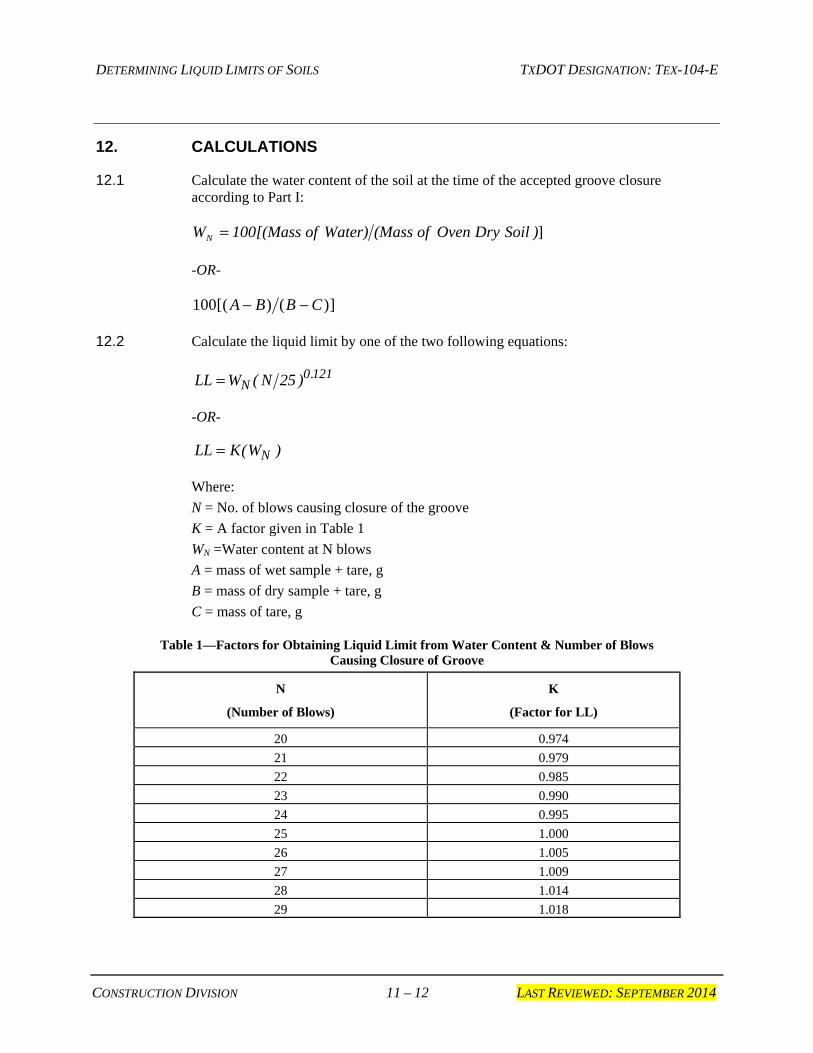
12. CALCULATIONS
12.1 Calculate the water content of the soil at the time of the accepted groove closure according to Part I:
])SoilDry Oven of (MassWater) of 100[(MassWN =
-OR-
])()([100 CBBA −−
12.2 Calculate the liquid limit by one of the two following equations:
LL W NN= ( ) .25 0 121
-OR-
LL K WN= ( )
Where:
N = No. of blows causing closure of the groove
K = A factor given in Table 1
WN =Water content at N blows
A = mass of wet sample + tare, g
B = mass of dry sample + tare, g
C = mass of tare, g
Table 1—Factors for Obtaining Liquid Limit from Water Content & Number of Blows Causing Closure of Groove
N
(Number of Blows)
K
(Factor for LL)
20 0.974
21 0.979
22 0.985
23 0.990
24 0.995
25 1.000
26 1.005
27 1.009
28 1.014
29 1.018
DETERMINING LIQUID LIMITS OF SOILS TXDOT DESIGNATION: TEX-104-E
CONSTRUCTION DIVISION 12 – 12 LAST REVIEWED: SEPTEMBER 2014
12.3 For low PI and non-plastic materials, when the two halves close or slide prior to 20 blows, determine the liquid limit (LL) as follows:
12.3.1 Perform Tex-107-E.
12.3.2 Calculate the Plasticity Index (LS = linear shrinkage in percent):
PI LS= ( . )1 6
12.3.3 Determine the Plastic Limit (PL) in accordance with Tex-105-E.
12.3.4 Calculate the Liquid Limit:
LL PI PL= +
13. REPORT
13.1 Report the liquid limit to the nearest whole percent.
Related Documents