Term of Reference Upgrading of IT Network (Phase II) I. BACKGROUND The project shall cover the upgrading of ICT network including network designs, supply, installation, configuration and testing of various ICT equipment and structured cabling for UP Mindanao, but shall not be limited to the following: 1. Design and configuration of the University Network for Two (2) Tier Spine-Leaf Architecture 2. Supply, installation, and configuration of multi-wan load balancer, fiber core switches, POE edge switches, WIFI access points, network cabinets, uninterruptible power supply (UPS); and 3. Installation and configuration of existing ICT Equipments: firewalls(Palo Alto PA 820 and PA 500),Wifi controller and access points (Aruba 7205 and it’s access points), VOIP Server (YEASTAR S300 and it’s IP Phones) and existing switches; and 4. Design, supply, installation and testing of structured cable system at the College of Science and Mathematics building, College of Humanities and Social Sciences building, EBL Dorm and ILC/LRC Building, CARIM, Faculty and Staff Housing and CHSS Cultural Center Building and other new buildings 5. Design, supply, installation and testing of Structured Cable System for the Access Points for the entire university 6. Assessment and Installation of Electrical Provisions for all the mentioned equipment in this Term of Reference that should meet the Industry Standards. II. OBJECTIVE In line with the government's focus on "advancing science, technology, and innovation" and the UP mandate to become a "research university" and "regional and global university," UP Mindanao aims to provide world-class facilities for the conduct and dissemination of research in order to increase research productivity of scientists in Mindanao and encourage collaboration with international scholars. The implementation of the Upgrading of IT Networks (Phase 2) will support the University in delivering research, instruction and extension to its stakeholders. III. APPROVED BUDGET FOR THE CONTRACT The Approved Budget for the Contract (ABC) is Fifty Million Pesos (P 50,000,000.00) through the General Appropriations Act of 2019 Capital Outlay inclusive of all government taxes and charges. IV. BIDDER’S QUALIFICATIONS 1. The Bidder must have an employed Certified Project Management Professional (PMP) or its equivalent. Must attach valid certification certified true copy by the issuing entity.

Welcome message from author
This document is posted to help you gain knowledge. Please leave a comment to let me know what you think about it! Share it to your friends and learn new things together.
Transcript
Term of Reference
Upgrading of IT Network (Phase II)
I. BACKGROUND
The project shall cover the upgrading of ICT network including network designs, supply,
installation, configuration and testing of various ICT equipment and structured cabling for
UP Mindanao, but shall not be limited to the following:
1. Design and configuration of the University Network for Two (2) Tier Spine-Leaf
Architecture
2. Supply, installation, and configuration of multi-wan load balancer, fiber core switches, POE
edge switches, WIFI access points, network cabinets, uninterruptible power supply (UPS); and
3. Installation and configuration of existing ICT Equipments: firewalls(Palo Alto PA
820 and PA 500),Wifi controller and access points (Aruba 7205 and it’s access points),
VOIP Server (YEASTAR S300 and it’s IP Phones) and existing switches; and
4. Design, supply, installation and testing of structured cable system at the College of Science
and Mathematics building, College of Humanities and Social Sciences building, EBL Dorm and
ILC/LRC Building, CARIM, Faculty and Staff Housing and CHSS Cultural Center Building and
other new buildings
5. Design, supply, installation and testing of Structured Cable System for the Access Points for
the entire university
6. Assessment and Installation of Electrical Provisions for all the mentioned equipment in this
Term of Reference that should meet the Industry Standards.
II. OBJECTIVE
In line with the government's focus on "advancing science, technology, and innovation" and the UP
mandate to become a "research university" and "regional and global university," UP Mindanao aims
to provide world-class facilities for the conduct and dissemination of research in order to increase
research productivity of scientists in Mindanao and encourage collaboration with international
scholars. The implementation of the Upgrading of IT Networks (Phase 2) will support the University
in delivering research, instruction and extension to its stakeholders.
III. APPROVED BUDGET FOR THE CONTRACT
The Approved Budget for the Contract (ABC) is Fifty Million Pesos (P 50,000,000.00) through the
General Appropriations Act of 2019 Capital Outlay inclusive of all government taxes and charges.
IV. BIDDER’S QUALIFICATIONS
1. The Bidder must have an employed Certified Project Management Professional (PMP) or its
equivalent. Must attach valid certification certified true copy by the issuing entity.

2. The Contractor must have at least One Licensed Electrical Engineer and One Licensed
Electronic Communication Engineer who are currently employed in the contractor's company
trained and certified in the design and installation of cabling systems.
3. Additional post qualification requirements:
● Letter from the Cabling System Manufacturer that it manufactures end-to-end structured
cabling system copper and fiber optic cables and their associated connecting hardware.
● Certification from Manufacturer's main/regional office stating that the contractor is an
Authorized Business Partner and Certified Installer of the Brand being offered (Switches and cabling).
4. The bidders must submit, in addition to the bidding documents and in a separate envelope, A
CERTIFICATION, UNDER OATH, CERTIFYING THAT THEY HAVE NO PENDING
CASE(S) AGAINST THE GOVERNMENT.
V. SCOPE OF WORK AND DELIVERABLES OTHER REQUIREMENTS
The bidder should conduct an actual site visit, they should submit a time-line (Gantt chart) of
activities as part of technical proposal and submit original brochure for items no. 1 to 9 of the
deliverables.
VI. DELIVERABLES
No. Particulars Quantity Unit
1 Fiber Core Switch 2 units
SFP/SFP+/SFP28 Transceivers(support
1GbE/10GbE/25GbE) 168 units
10GBASE-T Transceivers 20 units
QSFP+/QSFP28 Transceivers (support 100GbE) 8 units
6m Fiber Patch cord compatible with the
SFP/SFP+/SFP28 Transceivers 168 units
6m Fiber Patch cord compatible with the 100G
QSFP+/QSFP28 Transceivers 8 units
JD362B HPE X361 150W AC Power Supply for the
existing defective HP A5500 switch 2 units
2 Edge Switch POE 24 ports 11 units
3 Edge Switch POE 48 ports 12 units
4 42RU Network Cabinet 2 units
Monitored & Switched per Outlet PDUs (48 outlets) 10 units
5 24RU Network Cabinet 14 units
Monitored & Switched per Outlet PDUs (24 outlets) 28 units
6 Uninterruptible Power Supply (UPS) 2000VA 18 units
7 Multi-WAN Internet Load Balancer 1 units
8 Wireless Access Point 90 units
9 Structured Cable System 1 lot
Roughing Ins 1 lot

Consumables 1 lot
Labor, Design and Engineering and Project Management 1 lot
V. TECHNICAL SPECIFICATIONS
NETWORK EQUIPMENT
1. Fiber Core Switch (at least 2 units)
Location: 1 for Admin Building Data Center and 1 for the Proposed New Data Center
The core switch should have the minimum or better specifications at listed below
a. Performance:
● High-speed fully distributed architecture
● At least Provides 6.4Tbps for switching and 2,000 Mpps for forwarding. All switching and
routing are wire-speed to meet the demands of bandwidth-intensive applications today and in the
future.
b. Physical Interfaces:
● Compact 1U switch
● At least Model with 48 ports of 1GbE/10GbE/25GbE (SFP/SFP+/SFP28) and 8 ports of
40GbE/100GbE (QSFP+/QSFP28)
● SFP+ ports support an optional 10GBASE-T Transceiver.
● At least 48p 25G SFP/+/28 and 8p 100G QSFP+/28
● At least 6 Back-to-Front Fans
● At least 2 Power Supply Units included (650W 100-240VAC Front-to-Back Power Supply )
c. Management:
● SNMP
● RJ45 for Serial Console
● USB-Type A for file management only
● RJ45 Ethernet for OOBM
d. Three (3) Years Warranty
e. Globally known brand distributed in the Philippines via a locally declared company with
global standard certifications like ISO, ITIL and D&B and engineers certified of the said brand
f. Includes at least 168 units of compatible SFP/SFP+/SFP28 Transceivers (support
1GbE/10GbE/25GbE) must be compatible with the new EDGE Switch POE specified in this Term
of Reference for the 2 units of fiber core switch. Also must be compatible with the firewall (PALO
ALTO PA 820), HP A5500 Switch and existing switches
g. Includes at least 20 units of compatible 10GBASE-T Transceivers for the 2 units of fiber core
switch
h. Includes compatible 8 units 100G QSFP+/QSFP28 Transceivers and must be compatible with
HP A5500 Switch and the new EDGE Switches POE specified in this Term of Reference for the 2
units of fiber core switch
i. At least 168 units 6m Fiber Patch cord compatible with the SFP/SFP+/SFP28 transceivers,
EDGE Switches POE and core switches for the 2 units of fiber core switch
j. At least 8 units 6m Fiber Patch cord compatible with the 100G QSFP+/QSFP28 Transceivers,
EDGE Switches POE and core switches for the 2 units of fiber core switch
k. supplier must able to configure the the two fiber core switches (in two separate building) in a
two (2) tier spine-leaf architecture network with the new POE Edge Switches and existing switches
l. Supplier shall propose, create, configure and deploy a new university network design and
topology that maximize the capabilities of the new core switches, the EDGE Switches POE, Multi-
WAN Internet Load Balancer with the existing firewalls (Palo Alto PA820,Palo Alto PA500) and
switches and the existing centralized controller (Aruba 7205). This is also subject to the approval of
the end users.
m. Supplier shall configure the existing existing centralized controller (Aruba 7205), switches
and firewalls (Palo Alto PA820,Palo Alto PA500) and the new EDGE Switches POE, Core Switches
and the new Multi-WAN Internet Load Balancer specified in this Term of Reference with the
approval of the end users
n. Includes 2 units of JD362B HPE X361 150W AC Power Supply for the existing defective HP
A5500 switch and supplier shall install and troubleshoot the parts in order for the device to work.
o. power plugs must be compatible with the PDUs in this Term of Reference
p. The bidder must have at least:
i. one (1) Palo Alto Networks Certified Network Security Engineer to handle the implementation,
support and training and
ii. one (1) Palo Alto Networks Certified Network Security Consultant for the design and security posture
assessment.
iii. one (1) Aruba Certified Switching Professional and
iv. one (1) Certified Mobility Professional for the design, implementation and training
v.one (1) Certified Mobility Professional for the design , implementation and training
2. Edge Switch POE 24 ports (at least 11 units)
The edge switch POE should have the minimum or better specifications at listed below
a. Performance:
● At least System Switching Capacity: 880 Gbps
● At least System Throughput Capacity: 660 Mpps
● At least Stack Size: 10 member
● At least t Max. Stacking Distance: Up to 10 kms with long range transceivers
● At least Stacking Bandwidth: 200 Gbps
b. Physical Interfaces:
● At least 24x ports Smart Rate 100M/1G/2.5G/5GBaseT Class 6 PoE ports supporting up to
60W per port
● At least 4x 1/10/25/50G SFP ports
At least 2 field-replaceable, hot-swappable power supply slots. 2 power supply must be installed
● At least Delivers up to 1440W of Class 6 PoE Power
● At least Two field-replaceable, hot-swappable fan trays (included)
c. Management:
● SNMP
● RJ45 for Serial Console
● USB-Type A for file management only
● RJ45 Ethernet for OOBM
d. Three (3)) Years Warranty

e. Globally known brand distributed in the Philippines via a locally declared company with
global standard certifications like ISO, ITIL and D&B and engineers certified of the said brand
f. power plugs must be compatible with the PDUs in this Term of Reference
3. Edge Switch POE 48 ports (at least 12 units)
The edge switch POE should have the minimum or better specifications at listed below
a. Performance:
● At least System Switching Capacity: 880 Gbps
● At least System Throughput Capacity: 660 Mpps
● At least Stack Size: 10 member
● At least Max. Stacking Distance: Up to 10 kms with long range transceivers
● At least Stacking Bandwidth: 200 Gbps
b. Physical Interfaces:
● At least 48x ports Smart Rate 100M/1G/2.5G/5GBaseT Class 6 PoE ports supporting up to
60W per port
● At least 4x 1/10/25/50G SFP ports
● At least 2 field-replaceable, hot-swappable power supply slots. 2 power supply must be
installed
● At least Delivers up to 2880W of Class 6 PoE Power
● At least Two field-replaceable, hot-swappable fan trays (included)
c. Management:
● SNMP
● RJ45 for Serial Console
● USB-Type A for file management only
● RJ45 Ethernet for OOBM
d. Three (3) Years Warranty
e. Globally known brand distributed in the Philippines via a locally declared company with
global standard certifications like ISO, ITIL and D&B and engineers certified of the said brand
f. power plugs must be compatible with the PDUs in this Term of Reference
4. 42RU Network Cabinet (at least 2 units)
The 42RU Network Cabinet should have the minimum or better specifications at listed below
● 42 RU
○ Width: 800mm Depth: 1200mm
○ Welded and assembled steel frame construction
○ Easy maintenance powder coat finish
○ Adjustable rear equipment rails with continuous positioning, fixed front rails
○ Large cable entry/cable access
○ Doors include keyed swing handles
○ Side panels

○ Dual hinge door for maximum accessibility between adjacent cabinets
○ Cabinet supplied with 2 sets of high density cable management fingers
○ Cable entry holes are equipped with plastic sealing plugs
○ UL 2416 standard compliant and have been static load tested to at least 1,360kg (3,000 lb.)
○ Support Optical distribution frame or tray
○ EIA-310-E compliant
○ Rolling Load of at least 1,136kg (2,500 lb.)
○ Cabinet ships assembled, one per pallet
○ Cabinets include hardware kit: #12-24 screws, or M6 screws and cage nuts
○ Casters
○ At least 2 units of PDUs for each rack are included. Additional 6 units of PDU for the 3
existing Racks in the Admin Building Data Center. For the total of 10 units of PDUs. Installation
and configuration of PDUs to the different power sources are included.
○ Must be Monitored & Switched per Outlet PDUs. The primary input plugs into an On-Line UPS system. The secondary input plugs into a wall outlet. If the UPS system is taken offline for maintenance, repair or replacement, the PDU keeps the load powered by automatically switching from the primary input to the secondary input because of its ATS functionality. When the UPS system is restored, the PDU will switch back to the primary input. A switched PDU can locally monitor load level and avoid potential overloads with a built-in digital current meter, as well as remotely control individual outlets for the rebooting of locked equipment to avoid costly service calls, custom power-on/power-off sequences and load-shedding of non-essential loads during blackouts to extend battery backup runtime for critical equipment. Unused PDU outlets can be electronically locked off to prevent the connection of unauthorized hardware.
○ Each PDU should have a 48 number of outlets((36)C13, (12)C19) and should be the same
brand with a 24ru cabinet and 42ru cabinet in this Term of Reference. Input Plug of the PDU should be compatible with the new and existing UPS.
○ Support Angled Patch Panel
○ Clip nuts included
○ Inclusion of 35 units PDU Power Cord (C14 to C13) rated for core switches, switches, servers
5. 24RU Network Cabinet (at least 14 units)
The 24RU Network Cabinet should have the minimum or better specifications at listed below
a. Enterprise cabinet, 24 RU, single hinge perforated front and rear doors with keyed swing
handles, (2) solid single piece side panels with ┬╝ turn locks, and casters. Fully assembled.
Dimensions: 46.7H x 23.5W x 42.0D (1187mm x 600mm x 1070mm).
Color: Black
b. Rear Door Type: Single Hinge Perforated
c. Material: Steel
d. Front Door Type: Single Hinge Perforated
e. Number of Rack Units: 24
f. Casters: Yes
g. Static Load Capacity (kg): at least 567
h. Rolling Load Capacity (kg): at least 227
i. Finish/Coating: Powder-Coated
j. Standards Meet: EIA-310-D, TIA/EIA-942, RoHS Compliant, UL 2416

k. Cooling Architecture: Containment
l. Support Angled Patch Panel
m. Support Optical distribution frame or tray
n. at least 2 Units PDU for each rack. For the total of 28 units of PDUs for at least 14 units of
24RU Network Cabinet. Installation and configuration of PDUs to the different power sources are
included
o. Must be Monitored & Switched per Outlet PDUs. The primary input plugs into an On-Line UPS system. The secondary input plugs into a wall outlet. If the UPS system is taken offline for maintenance, repair or replacement, the PDU keeps the load powered by automatically switching from the primary input to the secondary input because of its ATS functionality. When the UPS system is restored, the PDU will switch back to the primary input. A switched PDU can locally monitor load level and avoid potential overloads with a built-in digital current meter, as well as remotely control individual outlets for the rebooting of locked equipment to avoid costly service calls, custom power-on/power-off sequences and load-shedding of non-essential loads during blackouts to extend battery backup runtime for critical equipment. Unused PDU outlets can be electronically locked off to prevent the connection of unauthorized hardware.
p. Each PDU should have a 24 number of outlets ((12)C13, (12)C19) (the same brand with 24ru
cabinet and 42ru cabinet in this Term of Reference). Input Plug of the PDU should be compatible with the new and existing UPS.
6. Uninterruptible Power Supply (UPS) 2000VA (at least 18 units)
The Uninterruptible Power Supply (UPS) 2000VA should have the minimum or better specifications
at listed below
a. Backup time of at least 9 minutes at full load Load capacity of 2000VA 1800Watts
b. Auto self testing system
c. Communication: USB/SNMP
d. On-Line UPS System
● Input and Output Voltage at 230 VAC with 60Hz
● No Load Shutdown
● Related cables and accessories
● Comes complete with sealed free-maintenance batteries
● UPS battery must have at least Three (3)years warranty
e. User Interface: LCD with audible alarm
f. Outlet Receptacle: 8 IEC C13 Outlets
g. power plugs must be compatible with the PDUs in this Term of Reference
7. Multi-WAN Internet Load Balancer
The Multi-WAN Internet Load Balancer should have the minimum or better specifications at listed below
Minimum specifications:

● Ethernet WAN Ports: 13 (GE) ● LAN Ports: 3 (GE) ● USB WAN Modem Port: 1 ● Recommended Users :1000-5000 ● Stateful Firewall Throughput: 5Gbps ● 802.1q VLANs Supported: 1024 ● Port-Based VLAN ● Load Balancing & Failover ● Load Balancing Algorithms: atleast 8 ● Drop-In Mode ● Inbound Load Balancing ● Cloud Management ● VPN ● Hot Failover ● WAN Smoothing ● Bandwidth Bonding ● VPN Throughput (256-bit AES)/(No Encryption) : atleast 800Mbps ● IPsec VPN (Network-to-Network) ● Number of IPsec Tunnels: atleast 400 ● Remote User Access ● L2TP VPN Server ● OpenVPN Server ● PPTP VPN Server ● Recommended PPTP/L2TP/OpenVPN Users: atleast 500 ● GRE (Network-to-Network): atleast 5 ● Bandwidth Usage Monitor ● QoS for VoIP and E-Commerce ● User Groups Bandwidth Control ● Web Blocking ● Full Web Filtering Blacklist ● LACP (802.3ad) NIC Bonding ● High Availability ● LAN Bypass ● FCC, CE, RoHS
● Warranty: Three (3) Years
power plugs must be compatible with the PDUs in this Term of Reference
8. Wireless Access Point (at least 90 units)
The Wireless Access Point should have the minimum or better specifications at listed below
Technical Specifications:
● AP type: Indoor, dual/tri-radio, 5GHz and 2.4GHz 802.11ax 4x4 MIMO
● 5GHz radio (dual-radio operation): Eight spatial stream Single User (SU) MIMO for up to 4.8Gbps wireless data rate with individual 8SS HE80 (or 4SS HE160)

802.11ax client devices, or with eight 1SS or four 2SS HE80 802.11ax MU-MIMO capable client devices simultaneously
● 5GHz radio (tri-radio operation*): Four spatial stream Single User (SU) MIMO for up to 2.4Gbps wireless data rate with individual 4SS HE80 (or 2SS HE160) 802.11ax client devices, or with four 1SS or two 2SS HE80 802.11ax MU-MIMO capable client devices simultaneously
● 2.4GHz radio: Four spatial stream Single User (SU) MIMO for up to 1,150Mbps
wireless data rate with individual 4SS HE40 802.11ax client devices or with two 2SS HE40
● 802.11ax MU-MIMO capable client devices simultaneously
● Support for up to 1,024 associated client devices per radio* (typical recommended limit for active clients is 200), and up to 16 BSSIDs per radio
● Supported frequency bands (country-specific restrictions apply):
2.400 to 2.4835GHz (radio 1) 5.150 to 5.250GHz (radio 0 and 0L) 5.250 to 5.350GHz (radio 0 and 0L) 5.470 to 5.725GHz (radio 0 and 0U) 5.725 to 5.850GHz (radio 0 and 0U)
● Available channels: Dependent on configured regulatory domain
● Dynamic frequency selection (DFS) optimizes the use of available RF spectrum
● Supported radio technologies:
802.11b: Direct-sequence spread-spectrum (DSSS) 802.11a/g/n/ac: Orthogonal frequency-division multiplexing (OFDM) 802.11ax: Orthogonal frequency-division multiple access (OFDMA) with up to 37 resource units (for an 80MHz channel)*
● Supported modulation types:
802.11b: BPSK, QPSK, CCK 802.11a/g/n: BPSK, QPSK, 16-QAM, 64-QAM, 256-QAM (proprietary extension) 802.11ac: BPSK, QPSK, 16-QAM, 64-QAM, 256-QAM, 1024-QAM (proprietary extension) 802.11ax: BPSK, QPSK, 16-QAM, 64-QAM, 256-QAM, 1024-QAM
● 802.11n high-throughput (HT) support: HT20/40
● 802.11ac very high throughput (VHT) support: VHT20/40/80/160
● 802.11ax high efficiency (HE) support: HE20/40/80/160
● Supported data rates (Mbps)

802.11b: 1, 2, 5.5, 11 802.11a/g: 6, 9, 12, 18, 24, 36, 48, 54 802.11n: 6.5 to 600 (MCS0 to MCS31, HT20 to HT40), 800 with 256-QAM 802.11ac: 6.5 to 1,733 (MCS0 to MCS9, NSS = 1 to 4, VHT20 to VHT160), 2,166 with 1024-QAM 802.11ax (2.4GHz): 3.6 to 1,147 (MCS0 to MCS11, NSS = 1 to 4, HE20 to HE40) 802.11ax (5GHz): 3.6 to 4,804 (MCS0 to MCS11, NSS = 1 to 8, HE20 to HE160)
● 802.11n/ac packet aggregation: A-MPDU, A-MSDU
● Transmit power: Configurable in increments of 0.5dBm
● Maximum (aggregate, conducted total) transmit power (limited by local regulatory requirements):
2.4GHz band: +24dBm (18dBm per chain)
5GHz band: +27dBm in dual-radio mode, +24dBm in tri- radio mode (18dBm per chain)
Note: conducted transmit power levels exclude antenna gain. For total (EIRP) transmit power, add antenna gain.
● Advanced Cellular Coexistence (ACC) minimizes the impact of interference from cellular networks
● Maximum ratio combining (MRC) for improved receiver performance
● Cyclic delay/shift diversity (CDD/CSD) for improved downlink RF performance
● Space-time block coding (STBC) for increased range and improved reception
● Low-density parity check (LDPC) for high-efficiency error correction and increased throughput
● Transmit beam-forming (TxBF) for increased signal reliability and range*
● 802.11ax Target Wait Time (TWT) to support low-power client devices*
a. Locations of Wireless Access Points (WAPs) in all buildings and offices must be optimal to achieve total performance desired throughput.
b. WAPs have to be small, lightweight and can be securely deployed in a variety of locations such as on walls, cubicles, desktops, and in the ceiling.
c. The WAP antenna diversity should allow for the best possible signal processing using dual, Omni-directional antennas and directional antennas and other type of antennas that will assure signal strength in all areas.
d. WAPs should work with the existing centralized wireless controllers(ARUBA Controller 7205) to provide a high performance, centrally managed, wireless mobility solution for

UPMin network. WAPs should have an extended lifespan and can be configured manually or automatically across any L2/L3 network, allowing easy upgrades when new features, capabilities, or standards emerge.
e. WAPs should function as “thin” WAPs which would provide 802.11n with backward compatibility to a/b/g user access. Functions should also include but not limited to wireless user authentication, link layer encryption, VPN termination. Support roaming and low-latency handoffs between APs, ideal for handling delay-sensitive applications such as voice over wireless.
f. WAP 802.11 services must be controllable
g. WAPs must supports operation in the radio frequency bands that will take advantage of higher density AP deployment, better overlapping coverage and reduced interference from other technologies (medical equipment, microwave ovens, cordless phones, Bluetooth devices)
h. WAPs activity must be coordinated by an existing wireless centralized controller (Aruba 7205). Supplier shall propose, create, configure and deploy a new university network design and topology that maximize the capabilities of the core switches, the EDGE Switches POE, Multi-WAN Internet Load Balancer with the existing firewalls (Palo Alto PA820,Palo Alto PA500) and switches and the existing centralized controller (Aruba 7205). This is also subject to the approval of the end users.
i. RF Management software must be available to automatically support channel selection, power levels, load balancing and failover
j. WAPs must support Power-over-Ethernet standard 802.3af
k. WAPs must supports 802.11e and Quality of Service (QoS)
l. WAPs must support access via Ethernet
m. Necessary licenses of each WAPS must be included and installed by the supplier in the centralized controller (Aruba 7205)
n. Globally known brand distributed in the Philippines via a locally declared company with global standard certifications like ISO, ITIL and D&B and engineers certified of the said brand
9. Structured Cable System (at least 966 nodes)
GENERAL SPECIFICATIONS
a. Cat 6a Unshielded Twisted Pair (UTP) Cable shall be primarily used for distribution that will
run through from IDF to Switches and Routers.
b. All cable trays for horizontal home runs shall be sized accordingly based on the number of
nodes per floor with at least thirty percent (30%) provision for expansion. Minimum size of cable
tray should be at least 300mm width and 100mm depth (W x D);
c. All cable trays/ladder shall be powder coated or hot dip galvanized and all conduits for
horizontal home runs shall be PVC with connector coupling;
d. All conduits for the backbone cables shall be an Electrical Metallic Tubing (EMT) pipe with
connector coupling and all cable trays/conduit support or hangers shall be permanently anchored on
the ceiling.
e. Deployment and installation of network racks are related to structure cabling technical
implementation.
f. The length of each individual run of horizontal cable from the TR to the TO shall not exceed
90m
g. The Contractor shall observe the bending radius and pulling strength requirements of the
horizontal cable during handling and installation
h. Each run of cable between the TR and the TO shall be continuous without any joints or splices,
except where consolidation points are required
i. Installation practice shall comply to manufacture best practices
j. The cable manufacturer shall be ISO 9001 and 12001 registered
k. The contractor shall install/mount the new access points and the existing access points
provided by the end user
l.
m. The Locations of at least 966 nodes will be finalized once the project is awarded to the winning
bidder since new buildings may be finished during the duration of the bidding. The end-user has the
right to re-allocate the nodes depending on the availability of the new building.
ELECTRICAL WORKS
a. Electrical works shall comprise the supply and installation of power outlet (duplex type) per
workstation.
b. The installation of all electrical works shall be done in accordance with the provisions of
the latest edition of the Philippine Electrical Code, the laws and ordinances of the local code
enforcing authorities
c. The wiring to be used shall be 3.5mm sq. or better THWN or THHN concealed on modular
panel base plate and use of aluminum threshold for connection to other workstations. Use of Mica
Tubing shall be limited to a length of six inches (6”) on outlet termination and there shall be no open
wiring, no exposed or dangling wires seen at the work stations.
PASSIVE COMPONENT
1. Category 6a Cables
The Category 6a Cables should have the minimum or better specifications at listed below
a. Category 6A/Class EA cable shall be constructed of 23 AWG copper conductors with FEP
Plenum (CMP) insulation. The copper conductors shall be twisted in pairs and separated by a cross-
divider. All four pairs shall be surrounded by MaTriX tape and a flame retardant jacket. The advanced
MaTriX tape shall suppress the effect of alien crosstalk allowing 10Gb/s transmission, while
minimizing cable diameter. The innovative cable design shall provide installation flexibility as cables
can be routed in tight bundles through pathways and spaces
b. Horizontal cabling shall be 23 AWG, 100-Ohm, 4-pair UTP; UL/NEC CMR rated, round
design, round solid filler, non-bonded pairs, in white PVC jacket.
c. Cable jacketing shall be lead-free.
d. Cable performance characterized up to 600MHz.

e. Cables must not exceed 100 meter distance from the IDF/MDF
f. All cables must have fluke test result
g. Cable shall meet or exceed the performance requirements of ANSI/TIA/EIA-568B.2-1. Must
be confirmed by an independent testing laboratory.
h. Must be Gigabit Ethernet Zero-bit Error Rate tested and confirmed by independent testing
facility.
i. Cable shall be UL listed.
2. Category 6a Patch Panels
The Category 6a Patch Panels should have the minimum or better specifications at listed below
a. Loaded 24 ports CAT-6a Angled All Metal Shielded Modular Patch Panels loaded with
Shielded Jack Modules that support 10GBASE-T certified performance with the needed accessories
b. Category 6A/Class EA, 8-position, UTP jack module shall terminate 4-pair, 22 – 26 AWG,
100 ohm unshielded twisted pair cable and shall not require use of a punchdown tool. The
termination cap shall be color-coded blue to designate Category 6A performance and shall include
a universal label coded for T568A and T568B wiring schemes. The Mini- Com® TX6A™ 10Gig
UTP Jack Module must be installed as part of the TX6A™ 10Gig UTP Copper Cabling System to
achieve IEEE 10GBASE-T certified performance.
c. Patch panels shall be 1RU and provide 24 modular jack ports, with universal wiring that
maybe terminated to T568A or T568B.
d. Patch panel modular jacks shall be configured as 6-port, replaceable modules.
e. The front of each module shall be capable of accepting 9mm to 12mm labels. Each port shall
be capable of accepting an icon to indicate its function.
f. Patch panel shall terminate the building cabling on 110-style insulation displacement
connectors.
g. Patch panel shall meet or exceed the performance requirements of ANSI/TIA/EIA-568B.2-1.
h. Must have sensor strip conductive pads within the panel.
i. Must include a rear clip that secures and protects the mated connection of the sensor strip and
analyzer I/O cable assembly.
j. Patch panel must be UL Listed.
k. High density 1RU 48-port or 2RU 72-port configuration might be used if rack space is limited
3. Category 6a Data Outlet/Modular Jacks
The Category 6a Data Outlet/Modular Jacks should have the minimum or better specifications at
listed below
a. Category 6A/Class EA, 8-position, UTP jack module shall terminate 4-pair, 22 – 26 AWG,
100 ohm unshielded twisted pair cable and shall not require use of a punch down tool. The
termination cap shall be color-coded blue to designate Category 6A performance and shall include
a universal label coded for T568A and T568B wiring schemes. The Mini- Com® TX6A™ 10Gig
UTP Jack Module must be installed as part of the TX6A™ 10Gig UTP Copper Cabling System to
achieve IEEE 10GBASE-T certified performance.
b. Modular jacks shall be terminated using an 110-style pc board connector, color-coded for both
T568A and T568B wiring.
c. Category 6a modular jacks shall meet the performance requirements listed in
ANSI/TIA/EIA-568B.2-1.
d. Flexibility to support 180º or 90º cable termination with bend-limiting strain relief.

e. Modular jack shall be UL Listed
4. Faceplates
The Faceplates should have the minimum or better specifications at listed below
a. Must be surface-mounted, 2-port single-gang.
b. Each port shall be provided with an icon to indicate its function.
c. Faceplates shall accommodate two labels and provide a clear polycarbonate cover for each.
Faceplates shall be Stainless Steel Faceplate.
d. Should be compatible with the Category 6a Data Outlet/Modular Jacks in this Term of
reference
e. Should be the same brand with cat6a cable, Category 6a Patch Panels,
Category 6a Data Outlet/Modular Jacks
5. Category 6a Patch Cords
The Category 6a Patch Cords should have the minimum or better specifications at listed below
a. Category 6A/Class EA, UTP patch cords shall be constructed of 24 AWG stranded copper
cable with an enhanced performance modular plug on each end. Copper conductors in patch cable
shall be twisted in pairs and separated by a quadrant separator. All four pairs shall be surrounded by
matrix tape and a flame retardant jacket. The patent pending matrix tape shall suppress alien crosstalk
and allow 10 Gb/s transmission. Patch cord cable shall be offered in multiple colors and lengths for
design flexibility with a strain relief boot on each modular plug. All patch cords shall be compatible
with both T568A and T568B wiring schemes.
b. Patch cable assemblies must be factory-manufactured with stranded CMR UTP cable and
color-matched snag less rubber boots.
c. Work area at least patch cords (966 units) shall be at least 10 meters while equipment patch
cords at least (966 units) shall be 3 meters in length.
d. Must contain a 9th conductor that is external to the original copper cable assembly.
e. External probes must contact with a conductive pad on the sensor strip.
f. One patch cord per user outlet and equipment connectivity must be provided.
g. All Cat6a patch cords shall be factory terminated
h. All patch cord shall have Labels on it to provide identification of performance level, length
and quality control number
i. All patch cord shall be compatible with optional RJ45 plug lock-in device to prevent
unauthorized removal of cable, IP phone, other networking equipment, or critical connection
6. Cable Organizer
The Cable Organizer should have the minimum or better specifications at listed below
a. Horizontal cable management hardware must be 1 RU.
b. Must have black-coated finish.

Labeling
All jacks, panels and frames shall be clearly labeled. Labels should be tamper resistant and made with
a label maker at the station end. Data frames should be created with a label maker. Label color shall
be black on white and a CD/DVD copy of the labeling software including label sheets/package shall
be provided to UPMin. Label sheets shall be both laser and inkjet compatible.
CAT 6a UTP Cable Installations
Tester:
Shall pass the following end-to-end Testing Parameters using Level III Cable
● Attenuation
● Attenuation to Crosstalk Ratio (ACR)
● PowerSum Attenuation to Crosstalk Ratio (PSACR)
● Near End Crosstalk (NEXT)
● PowerSum Near-End Crosstalk (PSNEXT)
● Equal Level Far-End Crosstalk (ELFEXT)
● PowerSum Equal Level Far-End Crosstalk (PSELFEXT)
● Return Loss
● Propagation Delay
● Delay Skew
● Transfer Impedance
● Fluke test
Distribution of Nodes
Location Nodes
CHSS BUILDING 1ST FLOOR 72
CHSS BUILDING 2ND FLOOR 104
CHSS BUILDING 3RD FLOOR 8
CSM BUILDING 1ST FLOOR 272
CSM BUILDING 2ND FLOOR 242
Aruba Access Points 90
CARIM / OR, Staff Housing and other new Buildings Structured Cabling 178
VI. DELIVERY AND IMPLEMENTATION
1. The winning bidder shall submit Project Management Plan Fifteen (15) calendar days upon
receipt of Notice to Proceed for the implementation of the proposed solution that is subject for review
and approval of the UPMin. The project Management Plan Shall include but not be limited to the
following:

● Scope of Work
● Project Organization
● Implementation Methodology
● Project Timeline
● Communication and Deployment Strategy
● Capacity Building Program Strategy
The Project Management Plan should also include the deployment of project personnel to be assigned
in UP Mindanao in the duration of the project.
2. Supply, Delivery, Installation, Testing and Commissioning shall be within Sixty (270)
calendar days from the approval of the Project Management Plan.
3. The winning bidder shall submit manufacturer’s certification as the distributor or
dealer/reseller of the offered product as a requirement for issuance of Certificate of Acceptance.
VII. OTHER REQUIREMENTS
A. MAINTENANCE, SUPPORT AND WARRANTY
1. Provide Three (3) years maintenance support and services to include
● 12 Hours per day (Monday-Friday) Technical Support (should be physically Davao Based)
● Next Business Day Response Time
● Business Planning and Review
● Provide Comprehensive Disaster Recovery Procedure
● Project focal person where the UP Mindanao ITO personnel can directly communicate with
to address concerns
2. The Bidder shall provide technical support via telephone/fax, on-site assistance to resolve
technical and other related problems. Resolution can be delivered in the form of telephone, electronic
and/or on-site resolution. It shall refer to a condition wherein the reported problem is resolved by the
proponent to the satisfaction of the end-user. However, the end-users have the right to insist for on-
site resolution if the end-user wants it.
3. The proponent shall resolve a problem within twenty-four (24) hours after it was reported
by UPMin in any available and fastest means of communications.
4. Provide Four (4) hours response time for hardware and related problems and issues.
5. Established procedure on support and problem escalation
6. Provide at least two (2) on-call and on-site support personnel for three years after the
acceptance of the project.
7. Within the warranty period, equipment that cannot be repaired within twenty- four (24) hours
shall be immediately replaced with a service unit of similar specifications or better.
8. The Contractor shall guarantee that the entire structured cabling and networks are free from
all defective workmanship and materials, and will remain so for the period of:
● 20-25 Years of Product Warranty from the Cabling Manufacturer of the Product Offered.
● Minimum Three (3) Years Warranty on Workmanship
9. Inspection and cleaning of data cabinets, switches, and routers shall be done by the bidder on
a quarterly basis.
10. To provide monthly maintenance for the duration of the warranty period, adequate supply of
parts must be readily available.

B. RISK MANAGEMENT PLAN
The winning bidder shall submit a Risk Management Plan prior to UPMin’s acceptance. Risk
Management Plan shall include the following among others:
● Step by step procedures to be undertaken during disaster must be clearly identified to avoid
loss of data.
● Retrieval and restoration procedure that includes troubleshooting flowchart shall be
incorporated in the plan.
● Personnel responsible to undertake the plan and procedures shall be identified and drawn up
in the Risk Management Plan Organizational Chart.
C. PROVISION OF DOCUMENTATION
1. The solution provider shall provide a complete documentation for every deliverable and at
every end of each development stage and milestone which must be submitted to the Information
Technology Office for the approval. UPMin shall own any and all documents and shall reserve the
right to reproduce at no additional cost.
2. The documentation must be written in English of durable construction with concise and high
quality presentation to include but not limited to the following:
Technical Manuals
● As built documents
● Infrastructure Diagrams and Topology
● Troubleshooting and Installation Guides
● Single Line Diagram
● System/Operation Manual
● Documentation and Tagging Summary
Operational Manuals
● User Manuals (for Operations)
● Disaster recovery Plan
D. TRAINING AND TECHNOLOGY TRANSFER
1. The contractor must provide advance training for at least four (4) IT Personnel for the new
and existing ICT Network Equipment, basic troubleshooting for the Structured Cabling and
Management of the Data Center for at least five (5) days.
2. To ensure that proper maintenance and sustainment an appropriate training shall be conducted
by the proponent as Essential part of Technology Transfer to prepare and equipped UPMin and its
personnel in the overall operations and maintenance of its new Network Infrastructure and
architecture.
3. The proponent shall submit Program of Instruction (POI) detailing all the training activities
to be conducted for review, evaluation and approval of UPMin. Hands-on training shall form part of
the training program.
4. Operation and Training manuals shall be provided to each participant.
5. The Training shall be conducted and completed prior the formal turnover and

acceptance.
6. All expenses related to training (e.g. venue, meals, equipment, certificate..) shall be borne by
the proponent.
7. Venue of Training shall be determined by the proponents unless UPMin opted to conduct
said training inside UPMin premises.
8. Certificate of Participations/Attendance to Training/s shall be given to all participants.
E. REMOVAL OF DEFECTIVE UNAUTHORIZED WORK
Any defective work, whether the result of poor workmanship, defective materials, damaged through
carelessness or any other cause, found to exist prior to acceptance, shall be removed immediately and
replaced by work and material which shall conform to the approved specifications, or shall be
otherwise remedied in an acceptable manner. This clause shall have full effect regardless of the fact
that the work may have been done with the approval of UPMin or its representative.
IX. INSPECTION, TESTING, ACCEPTANCE AND PAYMENT
A. PRE-BID SITE INSPECTION
The providers may conduct a pre-bid site inspection so they could assess the needs of the end users
Actual Site Inspection Details:
Date and Time: April 5-13, 2021 from 9AM-4PM (except on Holidays and Weekends)
Contact Person: Prof. Vicente B. Calag, ITO Director
Contact Number: 092-57596645
Email: [email protected]
Meet-up location: ITO, G/F Administration Building, UP Mindanao, Mintal, Davao City
Safety Protocols: must wear face mask and face shield.
Site Inspection Certificate will be issued by the ITO.
Note:
1. Those who will conduct site inspection should inform the ITO via email ahead of time.
B.INSPECTION AND TESTING
1. All ICT Equipments, cables and termination hardware shall be 100% inspected and tested for
defects in installation and to verify ICT Equipments and cable performance under installed conditions.
Any defect in the ICT Equipments and cabling system installation including but not limited to cable,
connectors, patch panels, and connector blocks shall be repaired or replaced in order to ensure 100%
usable conductors in all cables installed.
2. Submit the corresponding reports of the testing conducted.
C. ACCEPTANCE
A certificate of acceptance for any of the bid items shall be issued by UPMin only after completion
of the scope of work and compliance to all the requirements.
C. PAYMENT

The source of funds for this project is the University of the Philippines System and payment shall
be made after the completion and acceptance of the project.

Layout
CHSS Building Ground Floor

CHSS Building 2nd Floor
CHSS Building 3rd Floor

CSM Building Ground Floor

CSM Building 2nd Floor
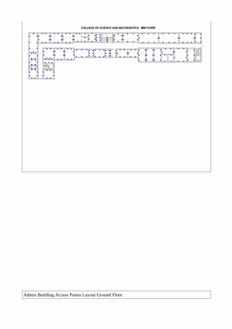
Admin Building Access Points Layout Ground Floor

Admin Building Access Points Layout 2nd Floor

Admin Building Access Points Layout 3rd Floor


CSM Building Access Points Layout Ground Floor

CSM Building Access Points Layout 2nd Floor

EBL Building Access Points Layout 1st Floor

EBL Building Access Points Layout 2nd Floor

Kalimudan Building Access Points Layout

HKC Building Access Points Layout
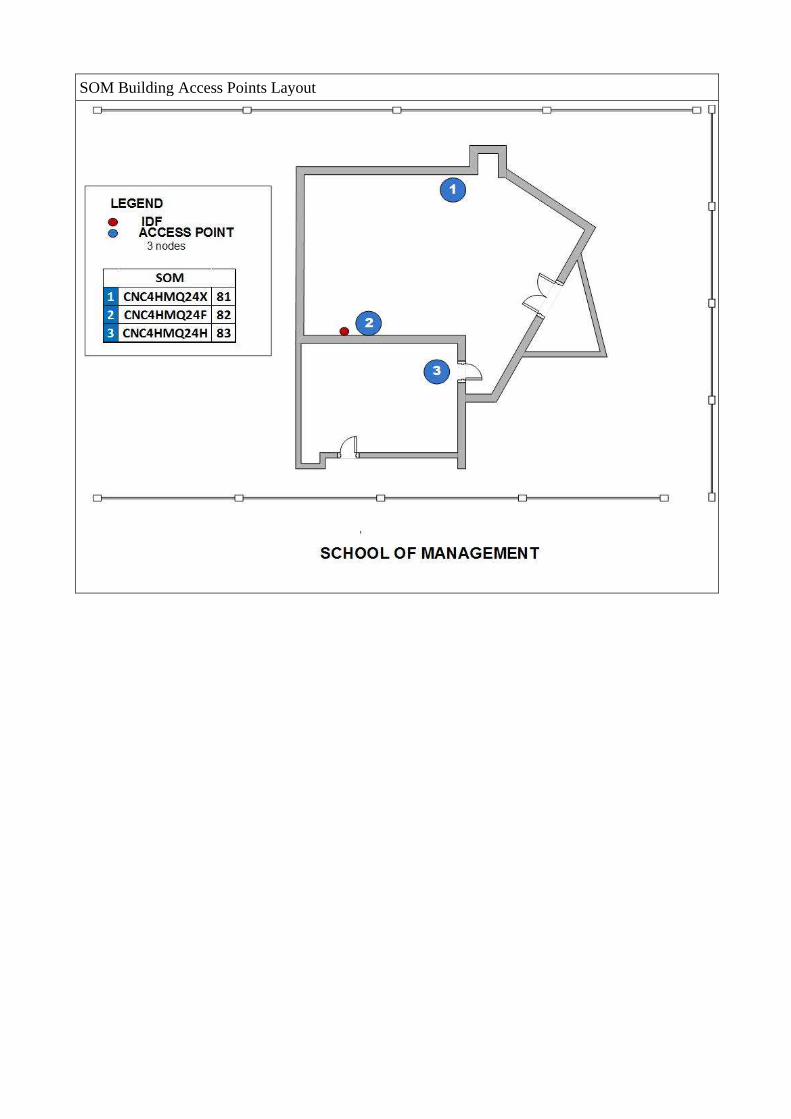
SOM Building Access Points Layout

Carim Building First Floor

Carim Building Second Floor

Fiber Optic Connections from Existing Admin Data Center to Existing Buildings

Fiber Optic Connections from Proposed New Data Center to New/Proposed Structures
Related Documents


