Improve Sofa Assembly through Automation and Redesign of the Processes Alex Peña Machine Design • Department of Design Sciences • LTH • 2010

Welcome message from author
This document is posted to help you gain knowledge. Please leave a comment to let me know what you think about it! Share it to your friends and learn new things together.
Transcript

Improve Sofa Assembly through Automation and
Redesign of the Processes
Alex Peña
Machine Design • Department of Design Sciences • LTH • 2010

Improve Sofa Assembly through Automation and Redesign of the Processes.
Copyright © 2010 Alex Peña
Published by:
Machine Design, Department of Design Sciences LTH
Lund University
P.O. Box 118
SE-221 00 LUND
Sweden
ISRN LUTMDN/TMKT-XX/XXXX-SE
Printed and bound in Sweden by Media-Tryck, Lund
i
Preface
The present Master Thesis enacts as the final step in completing my Computer
Science degree. It has been developed in the division of Machine Construction within
the Department of Design Sciences at Lunds Tekniska Högskola (LTH), Lund Uni-
versity.
First of all, I would like to thank our supervisor Gunnar Bolmsjö for the given support
during the thesis and without whom, it would not have been possible. I would also
like to thank Lena Forssell and Antonio Sellari from IKEA of Sweden for all their
assistance to guide us towards the right path.
Big thanks to Fede and Fabio for being the best lab mates in and out of the lab and for
supporting me every day. It has been a pleasure to work with you.
I would like to give special thanks to my parents and family for all the support given
along this year as well as during all my studies.
Lastly, I appreciate the encouragement received from all my friends either from Lund
or Barcelona. I would also like to add a special mention to my Erasmus friends from
Östra Torn, for the support given and the good moments that we have spent together
in Lund during this amazing year.
Tack så mycket,
Lund, June 2010
Alex Peña Domenech


iii
Abstract
Title: Improve Ektorp Sofa Assembly through Redesign and Automation of
the Processes.
Authors: Alex Peña, Department of Design Sciences.
Supervisors: Gunnar Bolmsjö, professor and director of studies, and Giorgos Niko-
leris, associate professor, at Lund University, Department of Design
Science at LTH. Lena Forsell and Antonio Sellari, at IKEA of Swe-
den AB, BA Living room & Workspaces.
Objective: To redesign the current assembly process of the Ektorp Sofa from
IKEA in order to improve cycle times, quality levels and to reduce, if
possible, costs associated with manufacturing, production times and
materials. IKEA wants to increase either the productivity or the quali-
ty standard of the Ektorp Sofa by simplifying the processes involved
in the construction of the sofa and modernizing the production line.
Method: By identifying problems and challenges for automation associated to
the current design of the sofa. Proposing new design for the base
frame and designing a respective assembly line for each solution.
Subsequently a simulation for each assembly line is done using Tec-
nomatix. Finally all the results obtained from each solution are ana-
lyzed, compared and discussed.
Conclusions: After a deep analysis of the sofa, it has been stated that the current
design has too many pieces that require a high number of operations
to assemble it. Moreover, it uses a huge amount of glue and staples.
Different solutions have been presented to improve the design. Addi-
tionally, two new base frame designs have been presented simplifying
the structure, reducing the number of pieces, the necessary assembly
operations and avoiding the use of glue or staples.
The current assembly process has also been redesigned in an auto-
mated assembly line layout and it has been proved through simulation
that the new line is faster than the current one. Moving the process to
a line arrangement has also increased the quality of the final product
as the operations in every stage are simplified and automated.
Keywords: Automation, Sofa furniture, Tecnomatix, Simulation, Assembly line,
Product analysis, Assembly sequence, Safety, Design for assembly.


v
Sammanfattning
Titel: Förändring av Ektop sofa genom omkonstruktion för att medge
automation av monteringen – Analys av nuvarande konstruktion
Författare: Alex Peña, Institutionen för designvetenskaper, avd för
maskinkonstruktion.
Handledare: Gunnar Bolmsjö, professor, inst för designvetenskaper, avd för
maskinkonstruktion, LTH. Lena Forsell och Antonio Sellari, IKEA of
Sweden AB, BA Living room & Workspaces.
Examinator: Giorgos Nikoleris, inst för designvetenskaper, avd för
maskinkonstruktion, LTH
Mål: Att ta fram en ny utformning av monteringsprocessen för Ektorp
soffa från IKEA i syfte att förbättra cykeltider, kvalitet, och reducera,
om möjligt, kostnader knutna till tillverkning och material.
Metod: Den nuvarande konstruktionen av soffan och dess produktionssystem
analyserades, och en målbild fasställdes. Därefter företogs en studie
hos produktionsföretaget varefter vissa ramar kunde fastställas.
Principer för lösningsförslag har tagits fram och utvärderats i samråd
med handledarna. Efterföljande validering med simuleringar för
automatiserad montering har utförts jämte analyser, jämförelser och
diskussion.
Diskussion: Analysen av soffan har lett till en reducering av antalet komponenter
och förenklingar i monteringsprocessen. Två nyasgtrukturer för
ramen i soffan har presenterats med förenklingar för att kunna
monteras effektivare med robot. Effektiviteten har visats genom
simuleringar.
Nyckelord: Automation, Soffa, Tecnomatix, Simulering, Monteringsline,
Produktanalys, Monteringssekvens, Säkerhet, Design för montering.


vii
Table of Contents
1 Introduction ................................................................................. 1
1.1 Background ........................................................................................................... 1
1.2 The companies ....................................................................................................... 1
1.3 Report Structure ................................................................................................... 2
2 Project Description ..................................................................... 5
2.1 Problem Formulation ........................................................................................... 5
2.2 Objective ................................................................................................................ 5
2.3 Scope....................................................................................................................... 6
2.4 Limitations ............................................................................................................. 6
2.5 Resources ............................................................................................................... 6
2.5.1 Time resources ..................................................................................................... 6
2.5.2 Physical resources ................................................................................................ 6
2.5.3 Software and multimedia ..................................................................................... 7
2.6 Method ................................................................................................................... 7
2.7 Project Plan ......................................................................................................... 10
3 Theoretical Basis [3]
................................................................... 11
3.1 Assembly Theory ................................................................................................. 11
3.1.1 Generating the feasible sequences ..................................................................... 11
3.1.2 Final choice ........................................................................................................ 17
3.1.3 Summary ............................................................................................................ 19
3.2 Design for Assembly............................................................................................ 20
3.2.1 Design for ”x” .................................................................................................... 20
3.3 Assembly System Design .................................................................................... 26
3.3.1 Basic factors in system design ........................................................................... 26
3.3.2 Average capacity equations ............................................................................... 30

viii
3.3.3 Resource alternatives ......................................................................................... 32
3.3.4 Assembly system architecture design ................................................................ 34
3.4 Assembly Workstation Design ........................................................................... 37
3.4.1 Description of the process in an assembly workstation ..................................... 37
3.4.2 Issues when designing an assembly workstation ............................................... 38
3.4.3 Important decisions ............................................................................................ 40
3.4.4 Design methods .................................................................................................. 40
3.5 The Tecnomatix Suite ......................................................................................... 42
4 Current Design Analysis .......................................................... 45
4.1 Disassembly for Analyze and Understand Product Operation ....................... 45
4.1.1 Steps for identifying the assembly issues in a product ...................................... 46
4.2 Preliminary Assembly Process Description ...................................................... 48
4.2.1 Frame assembly ................................................................................................. 48
4.2.2 Upholstery .......................................................................................................... 49
4.2.3 Sewing ................................................................................................................ 49
4.2.4 Cushions ............................................................................................................. 49
4.2.5 Quality ................................................................................................................ 50
4.2.6 Packaging ........................................................................................................... 50
4.3 Detailed Description, Problems and Challenges .............................................. 51
4.3.1 The base frame ................................................................................................... 51
4.3.2 The backrest ....................................................................................................... 57
4.3.3 The armrest ........................................................................................................ 60
4.3.4 Upholstery .......................................................................................................... 63
4.3.5 Cushions ............................................................................................................. 67
4.3.6 Final remarks ..................................................................................................... 69
4.3.7 Other recommendations and suggestions ........................................................... 70
4.4 Visit to the Factory .............................................................................................. 71
4.4.1 Company A ........................................................................................................ 71
4.4.2 Company B ........................................................................................................ 75
4.4.3 Visit conclusions ................................................................................................ 77
4.5 Matrix Summary ................................................................................................. 78
4.5.1 Number of pieces ............................................................................................... 78

ix
4.5.2 Material usage .................................................................................................... 79
4.5.3 Manufacturing times .......................................................................................... 79
4.5.4 Final results ........................................................................................................ 80
5 Improvements............................................................................ 81
5.1 Modifying the Current Design ........................................................................... 81
5.1.1 Removing internal supports ............................................................................... 81
5.1.2 Armrests internal structure ................................................................................. 82
5.1.3 Spring system ..................................................................................................... 82
5.2 Redesigning the Base Frame .............................................................................. 86
5.2.1 Push-in design .................................................................................................... 86
5.2.2 Click-in way ....................................................................................................... 89
5.3 Matrix Summary ................................................................................................. 96
5.3.1 Push-in design .................................................................................................... 96
5.3.2 Click-in design ................................................................................................... 99
5.4 Comparison between Designs .......................................................................... 103
5.4.1 Benefits ............................................................................................................ 103
5.4.2 Challenges ........................................................................................................ 104
6 Theoretical Model ................................................................... 107
6.1 Assembly Sequence Analysis: Current Design ............................................... 107
6.1.1 Liaison diagram ............................................................................................... 107
6.1.2 Bourjault method.............................................................................................. 113
6.1.3 Precedence relations diagram ........................................................................... 119
6.1.4 Final sequence .................................................................................................. 120
6.2 Steps for Joining the Pieces .............................................................................. 121
6.2.1 Assembly process ............................................................................................. 121
6.3 Assembly Sequence Analysis: New Designs .................................................... 124
6.3.1 Liaison diagram ............................................................................................... 124
6.3.2 Bourjault method.............................................................................................. 130
6.3.3 Precedence relations diagram ........................................................................... 134
6.3.4 Final sequence .................................................................................................. 134
6.4 Steps for Joining the Pieces .............................................................................. 136
6.4.1 Push-in design .................................................................................................. 136

x
6.4.2 Click-in design ................................................................................................. 138
7 Design of the Assembly Lines ................................................ 141
7.1 Overview of the Assembly Process: Current Design ..................................... 141
7.2 New Assembly Process: Current Design ......................................................... 143
7.2.1 Solution 1: Individual upholstery module ........................................................ 143
7.2.2 Solution 2: Integrated assembly line ................................................................ 145
7.3 Overview of the Assembly Process: New Designs .......................................... 155
7.4 New Assembly Process: New Designs .............................................................. 157
7.4.1 Assembly module ............................................................................................. 157
7.4.2 Foam module ................................................................................................... 161
8 Safety Framework .................................................................. 167
8.1 Employees .......................................................................................................... 167
8.2 Machinery .......................................................................................................... 168
8.3 Robots................................................................................................................. 168
9 Simulation Results .................................................................. 171
9.1 Current Design .................................................................................................. 171
9.2 New Designs ....................................................................................................... 174
10 Analysis .................................................................................. 177
10.1 Assembly Line for the Current Design.......................................................... 177
10.1.1 Workstation Times ......................................................................................... 177
10.1.2 Average Capacity ........................................................................................... 178
10.1.3 Challenges and Issues within Assembly Design and Simulations ................. 178
10.1.4 Conclusion ..................................................................................................... 179
10.2 Assembly Line for the New Designs .............................................................. 180
10.2.1 Workstation Times ......................................................................................... 180
10.2.2 Average Capacity ........................................................................................... 181
10.2.3 Challenges and Issues within Assembly Design and Simulations ................. 181
10.2.4 Conclusions .................................................................................................... 182
11 Further Work ........................................................................ 183
12 Conclusions ............................................................................ 185
References ................................................................................... 189

xi
Appendix A: Throughput Calculations ................................... 191
A.1 Company A Capacity ....................................................................................... 191
A.2 Current Design Capacity ................................................................................. 191
Appendix B: Throughput Calculations ................................... 193
B.1 Company A Capacity ....................................................................................... 193
B.2 New Designs Capacity ...................................................................................... 193
B.2.1 With the largest operation of 99 seconds. ....................................................... 193
B.2.2 With the largest operation of 78 seconds. ....................................................... 194
Appendix C: Fixture Design ..................................................... 195


1
1 Introduction
1.1 Background
According to Encyclopedia Britannica (2010) the furniture industry has its basis on
the early pieces made by craftsmen in the ancient China, India, Egypt, Mesopotamia,
Greece and Rome. In the 14th and 15
th centuries, after a poor household furnishing
during the early middle centuries, the furniture industry had a revival with many types
of cupboards, boxes with compartments and desks.
Later on, with the introduction of veering in Western Europe, Britain, North America
and the elsewhere, there was a revolution within the production techniques that al-
lowed to sophisticate the tasks done by carpenters and joiners. Therefore a new type
of industry arose: the cabinetmaker.
Finally, by the 19th century, together with the standardization of methods of manufac-
turing, there was a separation within the industry of those who made the furniture
from those who sold it. That is how modern furniture manufacturing industry was
born.
Sofa manufacturing, as it is nowadays, is directly derivate from this modern industry
of furniture manufacturing. Most of the modern techniques for sofa assembly rely on
the availability of shaping and handling different materials. Hitherto plywood, lami-
nated board and hardboard are the largest used materials around the world for sofa
manufacturing [10]
.
Since the „technological era‟ started several years ago, more and new methods has
been introduced into the industry: automated production for planks and large pieces
of wood, conveyors for transporting different pieces and pre-finished products be-
tween different stages, dedicated machinery for upholstering, cushion filling and a
whole developed system for packaging and delivery.
On this research we analyze, from an engineering point of view, the possibilities to
bring and to integrate those new technologies to the production of a specific type of
sofa furniture: the Ektorp Sofa from IKEA. All the steps, changes and design here
contained are though for decreasing assembly times, increasing quality standards and
innovating. In one word: improving.
1.2 The companies
The project was suggested by IKEA of Sweden to Lund University as a part of a big-
ger project that involves suppliers, design departments and selling strategies in order

Introduction
2
to improve the way how furniture is currently made, within the framework of the
IWAY created by them and, at the same time, introduced to the company in 20001.
IKEA is the world‟s largest furniture retailer, originated in Smålands, southern of
Sweden in 1943. Its products are focused on good design and functionality at low
prices, being the latter the cornerstone of IKEA vision and business idea. The IKEA
way is “to maximize the use of row materials in order to fulfill people‟s needs and
preferences by offering quality products at an affordable price” (IKEA 2010) [12]
.
In the list of the large amount of IKEA‟s suppliers, Company A, located in Poland
and founded in 2000 [13]
is one of the most important sofa manufacturing suppliers of
IKEA. Company A also designs and produces its own furniture. As a part of our
project plan, we did an empirical visit to the company‟s facilities located in Kalisz
(Poland).
1.3 Report Structure
Below a brief description of each part contained in the report:
Chapter 2.- Project Description
In this chapter it is done the formulation of the problem which we will work-
ing with throughout the study, along with the corresponding objectives, limi-
tations, the method used in each part for completing those objectives and the
project plan where it is shown the schedule of the different stages.
Chapter 3.- Theoretical basis
Some theoretical bases are necessaries for a correct formulation and analyses
of the models that we will be using. Here, we establish relevant concepts
about assembly processes, automation principles, as well as Tecnomatix‟s
fundaments.
Chapter 4.- Situation of the current design and its assembly line
This chapter is dedicated to describe the current design of the Ektorp sofa and
its associated problems for automation. We will also include here the empiri-
cal observations that we collected during a short visit to the factory in Poland.
1 The IKEA Way on Purchasing Home Furnishing Products, (IWAY) is based on international conventions and decla-rations. It includes provisions based on the United Nations Universal Declaration of Human Rights (1948), the Inter-
national Labour Organization Declaration on Fundamental Principles and Rights at Work (1998), and the Rio Decla-
ration on Environment and Development (1992). It covers working conditions, the prevention of child labour, the environment, responsible forestry management and more. Suppliers are responsible for communicating the content of
the IKEA code of conduct to co-workers and sub-contractors and ensuring that all required measures are implemented
at their own operations (IKEA 2010) [11].

Faculty of Engineering, Lund University
3
The names of both supplier companies will be changed due to confidentiality
reasons.
Chapter 5.- Improvements
This chapter presents different solutions that could improve the different
problems and challenges that have been detected during the analysis of the
sofa. Also new designs for the base frame are presented as well as a compari-
son between them and the current design.
Chapter 6.- Theoretical Models
From this chapter on the project is divided in three different cases that
represent the analysis for automation of the current design as well as the cor-
responding analysis for two new design proposals for the base frame: Click-in
and Push-in systems. Are described, analyzed and discussed the necessary
changes for automation and the materials suggested for their construction and
the assembly process for each case are modeled according to the theory de-
scribed in chapter 4.
Chapter 7.- Design of the Assembly Lines
Description of the suggested assembly line for each specific case including
number and types of machinery and/or robots, number of employees, cycle
times, number and type of sensors, number and type of fixtures, etc.
Chapter 8.- Safety Framework
Safety regulations and measures that each solution should include in order to
avoid accidents and to fulfill the requirements of the working environment es-
tablished by IKEA.
Chapter 9.- Results
Here we present and describe both theoretical and empirical (simulations) re-
sults obtained from the previous chapters.
Chapter 10.- Analysis
In this chapter all three cases are again considered and compared between
each other in terms of feasibility, time and costs. We also analyze the chal-
lenges that are necessary to meet if either of the solutions is considered to be
implemented, and the advantages concerning each design.
Chapter 11.- Discussion and further work
General perspective of the analyses previously done and the necessary infor-
mation for future researches to facilitate the designs and to improve the re-
sults.
Chapter 12.- Conclusions
Summation of the most important results obtained from the different cases, as
well as a rehash of the project‟s principal aims.


5
2 Project Description
2.1 Problem Formulation
The project first come out as the IKEA‟s willing of increasing quality levels in their
final products and to augment sofa furniture production, keeping manufacturing pric-
es within the same levels. There is also a need for a change of the way how furniture
has been made for several years. Nowadays, in the home furniture industry, despite of
large infrastructures and complex assembly lines, there are still several processes that
are handmade. Consequently, factors as tolerances, wrong connections, bad stapling,
over-gluing and many others, are more difficult to control and to correct than in a
machine automated system. Nevertheless, there are also many „human-made‟ opera-
tions that become much more complex when they are intended to be automated or
imitated by a machine. Therefore, the tradeoff appears between which operations can
be done by automation without increasing unnecessarily costs and complexity.
There is, as well, a willing for a change of the materials used in the manufacturing of
the (Ektorp) sofa. As stated before, wood has been, and still is, the most widely used
material in the home furniture industry due to its versatility for hand manufacturing.
However, when the thoughts are in automated manufacturing, wood becomes then a
very problematic material regarding tolerance levels, which directly affect repeatabili-
ty and production flow. Here, some challenges appear in this project related to eva-
luating the possibilities to change the materials used to build up the sofa within the
same IKEA‟s framework about stiffness, time-resistant and low cost production.
2.2 Objective
The main objective of this thesis is to design a new assembly process for the Ektorp
Sofa from IKEA in order to improve cycle times and quality levels. Another issue
will be to reduce, within the possibilities, the costs associated with production times
and materials. In addition, we will be able to establish a suitable design of both the
base frame of the sofa and its respective assembly line in a direction of increasing, not
only the productivity, but also, the quality standards.
For achieving this main objective, it is necessary to fix specific objectives that would
permit the successful accomplishment of the thesis:
To study and to analyze assembly operations in furniture production.
To introduce robot automation in large furniture production.

Project Description
6
To modify the current design of the Ektorp sofa to simplify operations for au-
tomation.
To propose a complete automated assembly system for the base frame of the
Ektorp sofa.
To compare the results obtained from the different designs and simulations.
To conclude the study by stating the improvements made in terms of quality,
time and costs.
2.3 Scope
The scope of this project is to design an assembly line for the Ektorp Sofa, applying
the necessary changes and improvements to the design, materials and assembly phas-
es in order to obtain an ease for automation of the processes involved in the built up
of the sofa. The validation of the designs will be done through software simulations.
2.4 Limitations
In this project, as in any other research, time is a crucial issue that can threaten the
fulfillment of the aims. Due to the wide approach that this thesis could have, we have
delimited our study by focusing on the design of an assembly line for the base frame
of the Ektorp sofa. Even though, our analysis of the problems and challenges for au-
tomation included in chapter 4 contained a complete description for all and each of
the parts of the entire sofa.
2.5 Resources
For performing the project fully and reaching our objectives we make use of several
resources, considering the limitations and the focus point previously defined.
2.5.1 Time resources
Our project is delimited in a space of time defined from January, 25th 2010 until June,
23th 2010, covering 20 weeks of work approximately. Holidays and non-working
days are considered within this period. For a detailed schedule see section 2.7. Project
Plan.
2.5.2 Physical resources
The design department assigned us a laboratory, equipped with three computers and
the corresponding facilities for developing the main part of our project. We also
worked with a sample of the Ektorp sofa delivered to us by IKEA. Latterly, we made
use of acrylic plastic to print on it some scaled models of the new designs of the base

Faculty of Engineering, Lund University
7
frame, by means of a laser cutter available in the department where this thesis was
hold.
2.5.3 Software and multimedia
All of the computers located in the laboratory had access to Internet and to the inter-
nal net of the university.
We also used three different programs, which permitted to successfully complete our
main objectives:
Tecnomatix v9.1:
Computer based simulation software developed by Siemens PLM where it
can be built up a whole work environment including machines, human be-
ings, conveyors, security equipment, etc.
NX v7.0.0.9:
Computer Aid Design (CAD) model software also developed by Siemens.
Using this program it is possible to sketch, draw and model different kind of
pieces that were necessary to modify or to design for completing the project.
2.6 Method
The project approach is divided in nine main steps that constitute the methodology
used for carrying out the fulfillment of each sought objective described before in this
chapter. In figure 1 it can be seen a chart flow summarizing all the stages involves in
the methodology used as well as a brief description for each step. Below, is described
in detail each one of the steps shown in the flow chart.
Analyzing the current design of the Ektorp sofa:
As the very first process done in this project, we decided, in agreement with
our supervisors, to identify and to analyze all the problems in the current de-
sign of the Sofa and the possible challenges that would have to be met when
designing the corresponding assembly lines. Therefore, a sample of the Ek-
torp sofa was given to us and consequently we disassembled all the necessary
parts.
We spent several days to understand the assembly process as it is currently
done and to identify all the pieces used to build up the sofa. We also received
the corresponding CAD models of the sofa. All the data collected during this
step was put together in a report and it can be found in sections 4.2 and 4.3.
Redesign of the Base Frame:
Once all the problems and challenges were identified, the company requested
us, as a feedback, to propose alternative designs for the base frame that would
permit a better and simpler assembly process. We sketch and drew our first
proposals using creativity and logic, without applying the corresponding

Project Description
8
theory, due to the willing of IKEA of following a different sequence of prod-
uct development.
For drawing this new designs, we used the modeling software NX 7.0.0.9 de-
veloped by Siemens. We documented all the designs made, together with a
complete description of each piece and its functionality.
Figure 1.- Methodology chart flow
Designing the assembly lines:
Within the lines of the same method used for creating the new designs of the
base frame, we proposed a first look-over of the assembly lines for both, the
current design and the new ideas.
Empirical study:
After a brainstorming of our main ideas and the analysis done with the infor-
mation given by the company, we went visiting the Company A factory fa-
cilities in Kalisz (Poland) as a part of the empirical study of the project. Dur-
ing the visit we were explained how each process for building the sofa is
done, the recently changes made to each department and the company‟s fu-
ture plans about the line production. We also were able to take note of the
times spent in each process as well as the number of employees and specia-
lized machinery. The visit was described and put together in a document

Faculty of Engineering, Lund University
9
summarizing the most relevant conclusions. The report can be found in sec-
tion 4.4.
Modifying the base frame designs:
With the data collected during the visit, we realized that the designs we did
before needed to be modified in order to simplify the amount of operations
involved in the assembly process. This time, we also made use of the theory
presented in chapter 3 of this report about design for automation as guidance
for the final prototypes. We were asked to choose two of these proposals for
being fully developed (assembly line, testing and simulations) together with
the current design. For this task we followed the preferences of our supervi-
sors expressed during one of the periodical meetings we hold.
Modifying the assembly lines:
With the new designs already tested and with the information about assembly
times, employees, machinery and other resources obtained from the empirical
study we formally designed the corresponding assembly line for the two cas-
es: the current design and new proposals. We also made use of the assembly
sequence theory described in section 3.1.
Computer Based Simulations:
All the information necessary for performing a full simulation of the assem-
bly lines were already developed. With all the data of the respective CAD
models and the description of the assembly lines, we used the Siemens PLM
software „Tecnomatix‟ for creating the simulations associated to each one of
the study cases.
Results and conclusions:
For finishing the project we made a comparison between the different solu-
tions that were proposed, analyzing the benefits and challenges for implemen-
tation and a brief business case for exploring the feasibility of the solutions.

Project Description
10
2.7 Project Plan

11
3 Theoretical Basis [3]
3.1 Assembly Theory
An assembly sequence is a set of unions or steps assigned to the available resources
and given in a specific order (Whitney 2004). The importance of a good assembly
sequence has usually been forgotten in favor of the design of the final product and its
parts. The result of this situation is the subsequent implementation of an inefficient or
non-optimized assembly. For this reason, in this section we want to offer a method to
obtain an improved and efficient assembly order.
Within the field of assembly analysis, the method we have chosen is based on the use
of Liaison diagrams and the Bourjault´s method, both explained later in this section.
According to the common terminology used in assembly analysis, we usually talk
about generating a collection of feasible assembly sequences. With feasible we mean
all the possible assembly orders without taking into account the difficulty, the cost,
the necessary time or any other quantifier.
In order to gain efficiency on the assembly process, it is important to introduce the
assembly sequence analysis in the early product design. Consequently, the final de-
sign will achieve the quality and ease of assembly required within the stated costs.
Leaving the assembly analysis after the definitive design could force a complete rede-
sign of one or more parts in order to get a feasible mating sequence.
After generating all the feasible sequences, the assembly engineer, or any other re-
sponsible for the task, has to perform the second phase in the process that it is to de-
cide which the better assembly sequence for the current product is. This decision is
subject to different considerations and also to the previous experience of the person
examining the possible solutions. A typical way to proceed is to start imposing some
physical restrictions attending the available framework for the production. For exam-
ple, at this point we can do a first prune depending if we are considering manual or
automated work. Then, the remaining sequences can be quantified for further compar-
ison based on the required assembly time, the number of orientations, number of fix-
tures, ease for workers, safety, costs, and so on.
3.1.1 Generating the feasible sequences
In order to create feasible assembly sequences we will follow a lineup as it is shown
in the diagram in figure 3. The flowchart was extracted and adapted from figure 7-3
in (Whitney 2004) [3]
.

Current Design Analysis
12
Design engineers are often unaware of the assembly during the design process, there-
fore we will start the assembly analysis using preliminary drawings and sketches as
the initial point. The earliest we start with the analysis, the easier it will be to apply
major or minor changes to the whole design.
All the steps of the diagram in figure 3 will be explained below in detail.
Figure 3.- Flowchart for generating the Feasible Assembly Sequences
3.1.1.1 Generate the Liaison diagram
In assembly structures, it is needed and important to represent all its parts as a dia-
gram that describes clearly a subassembly part or the whole product. In this kind of
diagrams each part is represented by dots and the mates between them are represented
by lines. Each one of these mates or unions is also called liaison.
These graphs are commonly known, from an assembly point of view, with the name
of Liaison diagrams. Using this diagram and drawings of the assembly product, in
most of manufacturing processes, it can be explained and known which parts com-
pose the product and how are they mated.
Figure 4.- Simple structure with its Liaison diagram
Faculty of Engineering, Lund University
13
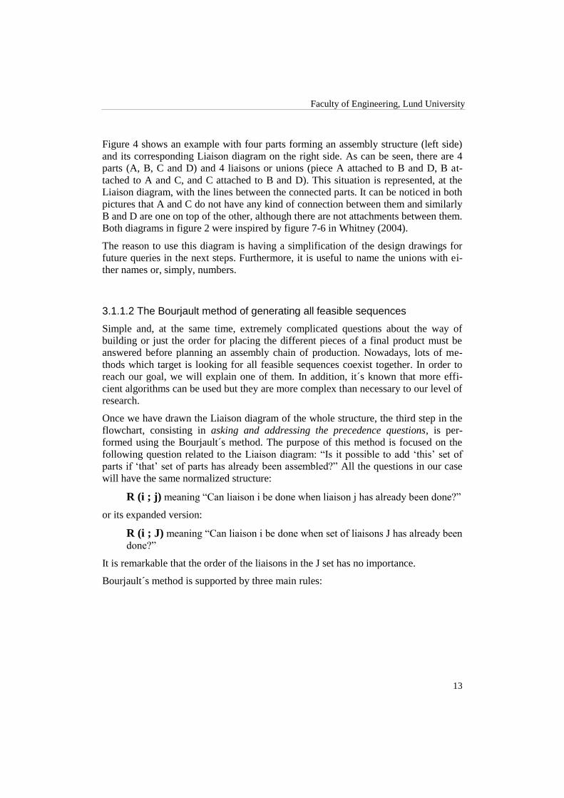
Figure 4 shows an example with four parts forming an assembly structure (left side)
and its corresponding Liaison diagram on the right side. As can be seen, there are 4
parts (A, B, C and D) and 4 liaisons or unions (piece A attached to B and D, B at-
tached to A and C, and C attached to B and D). This situation is represented, at the
Liaison diagram, with the lines between the connected parts. It can be noticed in both
pictures that A and C do not have any kind of connection between them and similarly
B and D are one on top of the other, although there are not attachments between them.
Both diagrams in figure 2 were inspired by figure 7-6 in Whitney (2004).
The reason to use this diagram is having a simplification of the design drawings for
future queries in the next steps. Furthermore, it is useful to name the unions with ei-
ther names or, simply, numbers.
3.1.1.2 The Bourjault method of generating all feasible sequences
Simple and, at the same time, extremely complicated questions about the way of
building or just the order for placing the different pieces of a final product must be
answered before planning an assembly chain of production. Nowadays, lots of me-
thods which target is looking for all feasible sequences coexist together. In order to
reach our goal, we will explain one of them. In addition, it´s known that more effi-
cient algorithms can be used but they are more complex than necessary to our level of
research.
Once we have drawn the Liaison diagram of the whole structure, the third step in the
flowchart, consisting in asking and addressing the precedence questions, is per-
formed using the Bourjault´s method. The purpose of this method is focused on the
following question related to the Liaison diagram: “Is it possible to add „this‟ set of
parts if „that‟ set of parts has already been assembled?” All the questions in our case
will have the same normalized structure:
R (i ; j) meaning “Can liaison i be done when liaison j has already been done?”
or its expanded version:
R (i ; J) meaning “Can liaison i be done when set of liaisons J has already been
done?”
It is remarkable that the order of the liaisons in the J set has no importance.
Bourjault´s method is supported by three main rules:

Current Design Analysis
14
Loop closure rule: If at some point in an assembly process, a loop of n liai-
sons stands with n-2 liaisons already made, then the next step applied to that
loop will close both open liaisons.
Subset rule: If R (i ; J) is yes, then R (i ; subset(J)) is also yes2 .
Superset rule: If R (i ; J) is no, then R (i ; superset(J)) is also no3.
On the other hand, some assumptions are also necessary when using this method:
Parts are rigid (otherwise we need a more complex analysis).
Liaisons stay made once they are made.
Using these rules and assumptions, the method starts asking per each liaison in the
Liaison diagram whether it is possible or not to made it when all the rest are already
made. If the answer to this question is NO, we have to split the last question into new
ones. At this point, simple questions than the precedence appear in order to find out
which members, or combination of them, have caused the negative answer. The new
subquestions are created by generating all possible combinations while it is removed
a member of the already-made liaisons group (the set on the right hand side of the
questions). The same process will be followed until reaching positive answers. Figure
5 shows the set of questions resulting from a starting question, taking as example the
diagrams presented in figure 4.
Figure 5.- Subquestions resulting from R (1 ; 2,3,4)
2 Subset is the collection of parts containing fewer pieces than the one on analysis. The rule is verifiable
as we know that J does not contain any parts that blocks the addition of the part i. 3 Superset is the collection of parts containing additional pieces than the one on analysis. We know that if
J contains parts that blocks the addition of i, then adding more parts to the already form set will not
change that situation.

Faculty of Engineering, Lund University
15
The number of questions depends on the amount of liaisons in the diagram. Each
question must be formulated for all different links between the parts. The order of the
question does not have any importance so it can be done randomly.
There exist other recent methods that also consider the Liaison diagram to be studied.
For example, there are some called “onion skin methods” that try the several cuts that
can be done to the Liaison diagram splitting the parts in two groups. Then the ques-
tion is changed to “Can this set of parts be added to that set of parts?” where the cuts
make the division between the two groups of parts. Therefore, in our research, we will
take into account this important procedure in order to reduce the number of questions.
3.1.1.3 Generate precedence relations for assembly sequences
The answers to these questions are, in this step, used to describe all specific relation-
ships within the Liaison diagram. Furthermore, we will conclude that some combina-
tions of liaisons must be done before other ones. Those results are expressed as ma-
thematical equations, i.e, i > = k,l. This means that the liaison i must occur before (>)
or at the same time (=) as k and l. Figure 6 shows the resulting relations for the exam-
ple in figure 5.
Figure 6.- Resulting relations for questions in figure 5
Once we have all the relations for the Liaison diagram using the Bourjault´s method,
we will take profit of the conclusions that we have reached, thus, we will be able to
build the diagram of the precedence relations for the assembly sequences. This dia-
gram represents relations described by “liaison in left hand side has to be done before
liaisons on the right hand side of the arrow”.
In the figure below, we can observe and example of this diagrammatic summary of
the relations. For example, we can state that “liaison 1 must be done before liaisons 3
and 4” and “liaison 1 must be done before liaisons 2 and 3”.
Figure 7.- Precedence relations diagram for the relations in figure 6
Examining this diagram, we can find out the candidates to be the heading of the se-
quence. These are the sets of liaisons that do not appear on the right hand side of an
arrow, also called unprecedented. In our example, attending that we have three possi-
ble combinations to generate a set of two elements with liaisons 2, 3 and 4, the only

Current Design Analysis
16
candidate that does not appear is (2,4). So in this example the only candidate se-
quence is (2,4) > (1,3).
3.1.1.4 Generate graph of sequences
Once we have the final list of feasible sequences it is time to choose the best one to be
implemented. Usually we will have a list of possible sequences made up of sets of
liaisons. Each of these sets represents a possible subassembly. The liaisons that re-
main together in a set can be done in any order.
A possible graphical representation for the list of feasible sequences is the Liaison
sequence diagram. This diagram is a tree or graph representation with the different
states representing the subassemblies in the precedence list and the arcs representing
the possible transitions. Each state is a set of boxes, one per each liaison in the struc-
ture. If the box is filled-in the liaison is already done. On the other hand, empty boxes
are undone liaisons. Figure 8 shows the Liaison sequence diagram for the candidate
sequence (2,4) > (1,3).
Figure 8.- Liaison sequence diagram for sequence (2,4) > (1,3)
A first phase in this situation is choosing one of the feasible sequences. To end with
this selection we have to decide, for the chosen sequence, the order of the liaisons
forming the different sets within it. In other words, choose a path within the Liaison
sequence diagram starting from the top state and ending in the bottom state. After this
we will finally have a valid sequence, i.e. could be 4 > 2 > 1 > 3, as shown in red
lines in figure 9.

Faculty of Engineering, Lund University
17
Figure 9.- Path for the selected sequence 4 > 2 > 1 > 3
3.1.2 Final choice
Normally, the choice for a good assembly sequence is a decision that belongs to the
industrial or manufacturing engineers. Once they have the list of relations, the prece-
dence relations diagram and the Liaison sequence diagram product of the products,
they have to consider all their knowledge about the available assembly framework as
well as their experience to choose the best path.
There are lots of factors and reasons which the decision of a good assembly bases on.
Illustrated in figure 10 there are some factors that are usually taken into account for
the final choice.
Starting from the bottom of the pyramid, related to construction reasons, considera-
tions like a good work area, the right way to place the tools as well as the involved
pieces that are taking part in the process make an important impact in the final deci-
sion. Topics like safety must also be considered within the working area. In other
words, ignoring this factor in each assembly process, could result in several difficult
part mates or fails in some maneuvers that would be detrimental either for the assem-
blers or the future assemblies and, therefore, a disaster in the assembly chain.
The quality control is another reason to take into account in order to reach the top of
the pyramid. Before choosing an assembly solution, we should consider the tests that
might be done to different parts or subassemblies. The best approach is performing
tests as early as possible, when the assembly has the minimum value added. Another
issue for this factor is to avoid placing early fragile parts to build up the final product
since the objective is to make the assembly as easier as possible and not the opposite.
Proceeding that way ensures we elude expensive rework in cases like, for example,
detecting a defective part when it is already buried beneath many others.

Current Design Analysis
18
Figure 10.- Reasons involved in the assembly sequence choice
About process reasons, we found that knowing that an assembly sequence includes
placement and movement of different pieces, the main target of the process reasoning
is to avoid as far as possible flipping-over the parts. Reorientation of the items, which
are taking part of the process, can be easy for people (if not too heavy parts) but
tricky for machines. Moreover, it could involve a costly situation if it is automated
not only because of the complexity, but the need of specific fixtures. In addition,
some replacement operations involving subassembly parts could cause possible dis-
mantle of pieces without any specific support to avoid it. If rotate operations cannot
be avoided, this trouble can be solved by carefully checking the state of the subas-
sembly in the instant in which we want to flip over. Anyway, a redesign of the subas-
sembly requiring the flip-over may be considered.
A right thinking is to take into consideration that a good assembly sequence is based
on splitting it in several subassembly stages and not making one part in a time. In that
case, it would be obvious to make subassemblies to stock, so the final product would
be done spending less time just adding only the remaining parts. These kinds of beha-
viors are commonly called production strategy reasons. That way of splitting in sub-
assemblies can be really useful if we decide to outsource the production of some of
them to one or more suppliers.

Faculty of Engineering, Lund University
19
Finally, time and costs play, as usually, an important role in the final decision. Quan-
tifying each possible solution is always a good way to compare different assembly
sequences. For this reason, calculating the necessary time to build the final product
with the candidate sequences, as well as obtaining the final price considering all the
fixtures, machinery, employees and other required resources can give us the definitive
factor to take the last decision.
3.1.3 Summary
The study of the assembly sequence was and still is an important issue for many fac-
tories around the world. Most of the structures and items that form part of a final
product, in the current globalized market, come from different suppliers and are nor-
mally built with different materials. For that reason, the analysis of the assembly se-
quence is a big challenge that many companies meet and carry out every day.
Once are known most of the factors that are involved in the final decision, it is time to
implement a method in order to reach all feasible assembly sequence processes. The
method that we have presented is based on two main phases.
In the first one all infeasible sequences are discarded. An impossible sequence ap-
pears when one or several parts of the assembly structure are blocking others and, in
addition, the final product assembly is unreached or is not as it would be expected.
Also mention that exist different kind of methods for implementing this phase. How-
ever, we have only focused and discussed the Bourjault´s method in order to study the
assembly sequences of our designs.
In the second phase, once all the infeasible sequences have been eliminated, it is im-
portant the participation of the engineers who will formulate criteria and will make
decision for choosing a good assembly sequence design. There is no algorithm to
implement the second phase. The selection of the adequate criteria is the only way to
success.

Current Design Analysis
20
3.2 Design for Assembly
Traditionally, products had simple designs so designers usually used to have know-
ledge of materials, mechanisms and also all the stuff related to either design or as-
sembly. Therefore, the assembly process was sometimes developed by the same
product designer (Boothroyd et altris 2005) [1]
.
Since some decades ago, and following an increasing trend until today, products have
been growing in complexity with complicated production and assembly methods.
Consequently, design and assembly planning are nowadays split parts of product de-
velopment. This makes the adaptation process of the product for assembly harder as
changes have to be discussed between two different teams that could even be physi-
cally separated. When following this structure, designers deliver a prototype and the
manufacturing team usually will only introduce some minor changes to adapt to mass
production (i.e. different thickness in a piece or different screws) because of the un-
certainty in whether a change would affect a functional requirement (Boothroyd
2002) [2]
.
Geoffrey Boothroyd, Peter Dewhurst and Winston Knight support a new way of
working adapting the old traditional way with the current complex design processes.
The difference with the old way is that nowadays a designer cannot hold all the ne-
cessary knowledge about production and assembly methods, so the new approach
considers designers and assembly engineers working together, facilitating the flow of
ideas and opinions in both directions during all the development of a new product.
Boothroyd and colleagues analyzed during 1970s a huge number of assembly
processes of commercial products in order to develop a way to optimize a design for
its assembly and to compare different solutions. The resulting method was called
Boothroyd Dewhurst method and it is widely described in their book “Product design
and manufacture for assembly” [2]
. With this method you can get a quantification of
the efficiency of your design as well as you can apply a simple process to redesign
your product to get a better assembly.
3.2.1 Design for ”x”
Design for ”x” or DFx represents a set if knowledge, procedures, analyses, metrics
and design recommendations developed to improve a product in the domain “x”.
These domains are called ilities and can be for example manufacturing, assembly,
disassembly, recycling, repair, etc.
Historically, DFx methods have been classified in two groups:
In the small: comprehends methods that can be applied only to one part at a
time by an engineer working alone.
In the large: enclose methods that involve all parts as a whole and conse-
quently it may be needed the participation of different engineers working in
different issues within the product design.

Faculty of Engineering, Lund University
21
As anyone can imagine, conflicts between DFx optimizations can appear, even more
if they are “in the large” methods. Discussion about this topic and specific descrip-
tions of DFx methods in the large and in the small are presented in next sections.
In order to gain the most benefit of DFx methods, they should be applied in the earli-
est possible stage of the design process because changes are considered to be relative-
ly easier to make. Ironically, much of DFx methods and recommendations deal with
details of the design that are unclear or undefined early in design.
The typical workflow when using DFx methods is summarized in this figure:
Figure 11.- DFx workflow
3.2.1.1 DFM/DFA
As we are working in the redesign of a sofa and its assembly process, we will focus
on methods, recommendations and guidelines oriented to manufacturing and assem-
bly. These are called design for manufacturing and design for assembly methods
(DFM and DFA).
The basic goals of both are make fabrication and assembly as much easier, less costly,
simpler and more reliable as possible.
To achieve these goals, the first step in most methods provide a scoring system to
evaluate each part of the design in terms of assembly time, difficulty to feed and as-
semble, chance of error and so on. The parts that get a lower score are therefore tar-
gets for redesign or remove. Boothroyd developed a collection of tables to get a score
for a part according to these characteristics available in (Boothroyd et altris 2001) [2]
.
The drawback of most scoring methods is that they work by analyzing isolated parts
out of context and hence ignoring many details of them. However, this fact simplifies

Current Design Analysis
22
the evaluation by the time it gives a list of parts that theoretically need to be im-
proved.
Next step usually considers all the parts at once and by adding some assembly process
criteria searches for the best product architecture.
Last step looks carefully at surviving and redesigned parts to see how their fabrication
and assembly can be improved.
However, independently of the method you use, there are some general DFM/DFA
recommendations [4]
that should be followed when designing a product:
Design the product to achieve the desired functions.
Pay attention to the cost during all the process.
Decide the best fabrication and assembly method and process for each part.
Design the part to suit the selection.
When deciding the assembly method, we should consider that a product that is easy to
assemble manually will usually be easy to assemble by machines, but, on the other
hand, part feeding is not too critical for people but the opposite for machines. On the
contrary, people needs more space to handle pieces and have to be able to see the
assembly action to ensure its accuracy.
A rule of thumb condensing all these issues is “Design a part as it can be assembled
one-handed by a blind person wearing a boxing glove” (Otto and Wood 2001)[5]
.
To decide the assembly process, we should take into account that cost can be saved if
the number of operations is reduced. Additionally, if standard parts are used it can be
even more reduced.
In the next two sections DFx in the small and in the large are described deeply, con-
centrating mainly in assembly (DFA) and in some points in manufacturing (DFM).
The Boothroyd Dewhurst method is explained for each part. This method has been
chosen because it is highly used, oriented to manufacturing and assembly, and is
based in a large number of product assembly analyses.
Other methods have also been developed, normally within a big company. Some ex-
amples are the Hitachi Assembleability Evaluation Method (AEM) [6]
, the Toyota
Ergonomic Evaluation Method[7]
or the Sony DFA methods[8]
.
3.2.1.2 DFx in the small
As said in the previous section, DFx in the small methods focus on the analysis and
optimization of individual parts. Basically, it is oriented to simplify handling (feed-
ing/grasping and orienting) and insertion of parts.
The Boothroyd Dewhurst method gives some general recommendations for both op-
erations [2]
. In the case of handling, they have the form of features that affect the oper-
ation:

Faculty of Engineering, Lund University
23
Nesting, tangling and fragility.
Need to use tools.
Physical characteristics (Size, thickness, weight, symmetry, flexibility, slip-
periness, stickiness).
Need for mechanical or optical assistance.
These rules apply to manual handling, but can be adapted similarly for automatic
feeding and grasping.
For the case of insertion operations, these are the main conditions affecting it:
The part is fastened immediately or after other operations.
The part stays put after being placed or the assembly must hold it until later
operations.
Accessibility and visibility of the insertion region.
Ease of aligning and positioning the part.
Need to use tools.
What Boothroyd and colleagues designed to quantify the effect of these features was
a set of tables that gives the handling and the inserting time. To calculate the assem-
bly time for a piece (handling plus insertion time) the table is indexed by the specific
characteristics, listed before, of each part.
However, the total time you get by consulting the tables does not give you any solu-
tion, but allows comparisons between solutions (i.e. a preliminary design and a possi-
ble redesign). For this reason, three main general guidelines are also given:
Avoid connections or make them short and direct.
Provide enough space to assemble.
Avoid adjustments.
As a final remark, any design change for ease of assembly cannot be done without
analyzing its impact on the cost of making the part thus generally parts themselves are
more costly to produce than to assemble.
3.2.1.3 DFx in the large
DFx in the large deals with design issues requiring consideration of the product as a
whole in the context of the product‟s life cycle. Mainly it focuses on product structure
and product simplification.
According to Whitney (2004) attending the product‟s structure, two architectural
styles are defined: array and stack. Array is the one consisting in placing parts on a
surface like for example printed circuit assembly. The stack architecture consists in
placing parts like in a pile. The justification, for this last style, relies on the effect of
the gravity aiding making a part stay put once is placed. There are two dominant in-
sertion operations: peg-hole and screws. Usually the dominant direction is vertical
from above. This second style is used either in the current sofa assembly or in the new
designs depending on the way their assembly is designed.

Current Design Analysis
24
When dealing with DFx in the large, usually we are working with simplification me-
thods. This is justified because simpler products have fewer parts and consequently
fewer assembly operations, workstations, workers, factory space and finally (in most
cases) less time and costs.
The Boothroyd method also applies to DFx in the large and offers a systematic ap-
proach for part number reducing by undergoing each part to three criteria. The result
is a theoretical reason to keep or eliminate each part. These are the three criteria [2]
:
“With product in operation, does the part move relative to all other already
assembled parts?”
“Must the part be of a different material or be isolated from all other already
assembled parts?”
“Must the part be separate from all other parts already assembled because
otherwise the assembly/disassembly of other parts would be impossible?”
The result of the method is interpreted according to the positive answers. Unless at
least one of the questions is answered yes for a part, that part can be combined with
another part or eliminated entirely.
As these are only theoretical results, the purpose is to focus attention on possibly un-
necessary parts. However, we can also calculate the assembly efficiency metric as
follows:
The numerator represents the minimum assembly time for a simple assembled prod-
uct for surviving parts. The denominator holds the current assembly time for the orig-
inal design which we are using as reference (could be the first design or a modified
one). The value of three seconds per part is an average calculated by Boothroyd after
the analysis of several commercial products [2]
.
As in the case of DFx in the small, Boothroyd and colleagues also give the following
general considerations to take the final decision after applying the three criteria:
This method was defined for manual assembly so, in some cases, it would be
needed extra criteria for automatic. Furthermore, usually, is difficult to know
in advance which assembly method will be used.
An assembly sequence must be chosen and considered before DFx as de-
scribed in previous section.
Assembly difficulty is hard to predict and many ways to reduce it exist.
Eliminating and consolidating parts can deprive the assembly process of
needed adjustment opportunities.
The final conclusion of this section is that any change in the large has to be checked
as it can affect any other issues like final functionality, efficiency, cost, etc. For ex-

Faculty of Engineering, Lund University
25
ample, consolidating two parts in one, when working with injected plastic, will reduce
the assembly time but on the other hand, will probably increase the complexity of the
mold and, consequently, the time to make it.
Current Design Analysis
26
3.3 Assembly System Design
Nowadays, most of the factories around the world invest huge amounts of money to
enhance and develop new sophisticated assembly system designs in order to be com-
petitive with the current industrial demand. These issues are becoming in crucial pro-
duction phases for the engineering departments of the companies and factories. In
order to have a successful quality and economic analysis of the final product, either
the architectures or techniques that are involved in the process chain will be essential.
In this theoretical part of the thesis, are discussed several factors in the manufacturing
systems. Furthermore, basic decisions that need to be made as well as some methods
and techniques that we will keep in mind when describing our assembly system are
mentioned. Suggestions for the current sofa design and the new ones are also de-
scribed.
3.3.1 Basic factors in system design
When a candidate product and its assembly sequence are available, it can be started
the assembly system design. It is extremely important consider that either the product
design or its assembly chains must be done in a parallel way since they depend on
each other. For that reason, both can be exposed to changes during the whole process
so as the higher capacity of variability of the assembly system and product designs,
the higher consideration of a good design. Some factors for the possible decision
when choosing the system design are shown below:
First, it is important to analyze the product, find out different production me-
thods and fulfill all requirements of the fabrication.
Select a feasible assembly sequence to use in the assembly system design.
This entire step has been explained in detail before (see previous section 3.2
Assembly Theory).
The production capacity is another relevant factor. Keeping in mind things
like break hours of the employees, time spent on changing some parts of the
system, machinery or robot reparations and other factors that decrease the ca-
pacity.
Compare techniques and feasible methods focusing on times and costs of fa-
brication.
Taking profit of common sense or using computerized help for addressing
people or equipments in order to build the product fulfilling fabrication rates
with an optimized cost.
Figure 12 shows a diagram where all the basic factors involved in the system design
are represented by circles. All of them are correlated and take part in the decision
making process.

Faculty of Engineering, Lund University
27
Figure 12.- Basic factors in the system design.
Capacity planning - Available time and required number of units/year
Each factory has its own control of production per hour, day and year. The
capacity planning is studied and applied in detail in order to fulfill fabrication
requirements imposed at the preliminary phases. The capacity of production
involves a specific speed at each workstation or subassembly system where it
is expressed in time per part or assembly.
Assembly resource choice
The technology used for the assembly design system is closely related with
the technical and economic analysis for different reasons explained in detail
below. Either design method or people are included in the definition of “re-
sources”. Most of the time, the mechanical equipments and items are de-
signed for specific parts of the assembly. This means that its operation range
is limited by either the assembly or the product design.
Finally, it is found out that some specific operations must be done by manual
work due to the product design. However, some tricky or unsafe parts, for
hand assembly, could cause failures in the assembly system or injured people.
System design
Capacity planning
Resource choice
Task assigment
Floor layout
Work statiton design
Material handling &
work transport
Part feeding &
presentation
Quality
Economic analysis
Personnel training and participation

Current Design Analysis
28
For these reasons, reconsiderations of the assembly system design must be
taken into account to avoid all those undesired problems.
Assignment of operations to resources
This factor is essential when deciding which parts of the system should be
done by which resources. Many alternatives appear for each operation and the
final choice is governed by cost and time. People are flexible, adaptable, but
compared to machines, they cannot work all the time or at the same high
speed.
The amount of production in the factory (in terms of required units per year)
has a huge impact in the assignment of operations to resources. Small prod-
ucts with several parts for building them are made in high volume scales
while large items in opposite way. The following scheme illustrates the de-
scribed situation.
Figure 13.-Basic decision between manual and mechanized assembly systems.
Note: “High Volume Scales” are considered roughly 100,000 units/year or
over this amount. It is noticed that as it is decreasing the variety the machines
are better. Otherwise, people will be needed when variety is high.
Floor layout
The logistic part that deals on the factories´ floor distribution is another point
to keep in mind in order to deploy the assembly system design inside them.
Production capacity
High Volume Scales
Machines are feasible
economically
Manual assembly may be necessary
technically
Low Volume Scales
Manual assembly is feasible
economically
Machines may be necessary technically

Faculty of Engineering, Lund University
29
Sometimes there are bad connections between subassembly parts, feeders,
workspaces and so on. This kind of situations would affect either economical-
ly and with several time downs along the productivity per day.
Workstation design
Each workstation must be designed in order to make easier the assembly
process. All parts must be properly placed and reachable. The same require-
ment appears with tools, machinery and so on. This part will be explained in
detail in the section 3.4 Assembly workstation design.
Material handling and work transport
In all assembly processes it is important to have an efficiency system which
allows managing different items, parts or subassembly products over the fac-
tory floor. Frequently, the transport is needed because the assembly process
goes rapidly. The amount of transporters, pallets and fixtures are important
because the capacity and optimization will be affected, directly, by these va-
riables.
It is responsibility of the designer to decide the transport method used in the
factory. One common discussion would be whether to use fixed conveyors
instead special vehicles. On the one hand, fixed conveyors are more feasible
economically, but from a flexibility point of view, they are not so proficient.
On the other hand, special vehicles give us the opposite situation.
Part feeding and presentation
At each workstation it is needed to have all parts used in the assembly
process. Feeders, pallets and so on are useful in order to transport different
parts from one place to another. This topic is also discussed in detail in the
section 3.4 Assembly workstation design.
Quality
When the product is on process to be assembled, all tasks happen rapidly so it
is common to overlook either mistakes or assembly failures during its produc-
tion. Thus, parts should be designed in order to avoid all this problems during
the assembly sequence.
Economic analysis
Some economic factors and requirements should be fulfilled within the whole
production. Economic analysis means discussing and deciding whether the
system design suggestions would be economically feasible or not. This analy-
sis is an important challenge for the assembly system design and must be kept
in mind in order to handle correctly the economic conditions where the com-
panies and factories are.
Personnel training and participation
It is known that the assembly processes entail a repetitive work. The em-
ployees must be constantly focused on their task along the work time to per-
form it as better as possible every time. On the one hand, the machinery will
be able to do the same tasks repeatedly. From this perspective, it is consi-

Current Design Analysis
30
dered more efficient than people. Nevertheless, most of the assembly
processes in furniture are done by people so far.
3.3.2 Average capacity equations
Many assembly systems are designed without a deep study of the alternative solu-
tions. It is common that the design staff work apart from the assembly system de-
partment. Against this, in our thesis we will suggest different designs of the current
product that have been created keeping in mind their assembly systems.
The most usual design method is “trial & error” which is based on proposing an as-
sembly system design and then testing it with discrete event computer simulation.
This technique is extremely limited since all changes will be done on the previous
assembly system without giving chances to different points of view in order to re-
structure the first design.
One of the most important issues for an assembly system designer is taking into ac-
count the system‟s capacity requirement. The effective rate of the system is measured
by the total number of operations required in order to complete one unit of a product.
Thus, extrapolating to a year:
where n is the number of operations needed per unit and Q is the amount of units per
year. Now, the conversion of this equation to operations per seconds is:
The number of seconds in operation in a year (Y) is calculated in the equation (w)
below. Considering an 8 hours working day (without considering holidays) this
means that in a year there are 255 operating days (depending on the company or fac-
tory) with a choice of n-shifts per day (1, 2 or 3 assuming at the same time that one
shift is 8 hours long).
In addition, another equation to measure the average capacity of production is made
by calculating the available operation time which is closely related with the last equa-
tion shown. The available operation time is just the inverse of equation [u], and gives
us the time spent performing each operation, then:

Faculty of Engineering, Lund University
31
[x]
The meaning of “operation” can be ambiguous depending on the context. For that
reason, all these equations must be clarified in order to make a good assembly system
design. The amount of operations needed in an assembly system is directly related
with the number of parts of the product. Other operations apart of inserting parts have
been considered, like finding out failures on them, applying lubrication, tool changes
and so on. In table 1 it is shown a typical operation time capability for different as-
sembly resources:
Table 1.- Typical operation time capability for different assembly resources
Resource Application Example Typical Operation Time
Person Small parts assembly 3-5 seconds
Robot Small parts assembly 2-7 seconds
Fixed automation Small parts assembly 1-5 seconds
Person plus lifting aids
and tools
Automobile final assembly 1 minute
Person plus lifting aids
and tools
Aircraft final assembly Several minutes – 1 hour
or over
Sometimes, there are several factors that increase the time a resource needs for an
assembly operation. These times must be considered in spite of they are not noticea-
ble at first time. The sum of each time will entail in the operation time analysis. For
that reason, it is needed to express the time of each resources performing an opera-
tion. The operation time needed is shown in equation [y] below:
Where,
Pure assembly time average time to do an operation based on fetching and inserting
the parts
In-out time time spent moving finished work out and placing new work in
Units/pallet 1 or more units per pallet
#Units/tool change number of units worked on before a tool change occurs (less
than units/pallets)
#Changes/unit number of tool changes needed to do one unit

Current Design Analysis
32
fractional uptime of the resource (number between 0 and 1)
Finally, taking profit of the last equation, we can calculate the total average time that
resources of a type will need to finish a product unit:
3.3.3 Resource alternatives
For the assembly system design it exists many resources alternatives, but they are
grouped in three main resource approaches: people, fixed automation and flexible
automation. Below, it is covered, for each case, the different advantages and disad-
vantages between them. All the discussion is focused in terms of assembly and fabri-
cation, dividing each resource alternatives into both its technical and economic cha-
racteristics.
3.3.3.1 People: manual assembly
Technical
The manual assemblers have been the most important resource since the be-
ginning of the industrial revolution. Its flexibility, responsibility and adapta-
bility to critical decision situated them over the top of the chain. People can
also make several operations at once, like placement and rotation of the posi-
tion of the parts, in contrast with the machines that usually cannot handle
many operations at the same time. However, these characteristics could be
counterbalanced by the efficiency, adaptability or dexterity of the machines.
In addition, people need to take breaks and eat. The normal rest is a break of
10 to 15 minutes in the morning and afternoon. 20 to 30 minutes of lunch
break are necessary for the middle of the day. As it was mentioned in equa-
tion [w] above, now, a shift becomes roughly 7 or 7.25 hours of the 8 hours
considered previously. In parallel with this, machines need maintenance and
sometimes repairs.
Nevertheless, manual assemblies are still quite important at the time to man-
age poorly understood systems and in some situations where testing
processes, adjustments or complex measurements are implemented.
Economic
In order to calculate the cost structure of this resource, we have to keep in
mind that the employees work in a range of speed with some thresholds de-
pending on their capacities, motivations, emotional situation and so on. Sev-
eral companies manage the payments of the employees according to the
amount of production reached by each assembler. However, the assembly

Faculty of Engineering, Lund University
33
cost per unit is roughly independent of the amount of production. In addition,
the more production needed the more employment volume required. If less
production is needed, more quantity of operations can be given for each as-
sembler or employed in another place due to their flexibility.
3.3.3.2 Fixed automation
Technical
This second resource alternative has been studied and developed during sev-
eral years. Increasing the speed, accuracy and so on, are the main tasks on
this approach. The typical fixed assembly machine is made with a chain of
identical workstations attached to a common synchronous conveyor. All the
workstations run at the same time doing the same processes in a series way.
Each station within the whole structure of the fixed machine adds, installs or
just tests one part at a time. Obviously, as the work is done simultaneously,
the production of the workstation and the whole structure is the same. Even if
we have automated systems with several automated machinery, it is needed
people in order to reload feeders, clean jams and tend to the machines. With-
out these employees, the machines will be able to continue working but most
companies prefer turning off the system during people breaks for safety rea-
sons.
Economic
Fixed automation presents a fixed cost since the amount of workstations is
roughly proportional to the numbers of parts in the assembly. This kind of
technique can produce high quantity of products, so due to this, it will be in-
expensive for a large volume production during several years (as long as
there are no changes in the assembly process requiring new machinery). In
addition, another economical way will be keeping the machinery working all
the time since stopping those workstations would mean that the whole struc-
ture will stop as well.
3.3.3.3 Flexible automation
Technical
This is the third resource alternative that implies all things related to the
world of automated systems with robots. Those machines are characterized
by different abilities like move with controllable degrees of freedom, forces
applied, and so on. The robots can do several operations at the same time like
rotate and place a specific part in an assembly system with a high speed and
accuracy. The main characteristics, for having a huge range of flexibility and
potential for adapting in new behaviors, are due to the possibility of their
computational control.

Current Design Analysis
34
Economic
As mentioned before a robot can do more than one task. In order to assembly
three different parts in a row, it is needed for a fixed automation system three
work stations doing the same thing while a robot can assemble the three dif-
ferent parts in a row. With this example it is shown the different costs be-
tween both approaches: cost of two more stations against two more tools for
the robot.
3.3.4 Assembly system architecture design
3.3.4.1 Single serial line
In 1913 Henry Ford invented a new design system where a belt or conveyor trans-
ported the work for the operators. This kind of assembly solution is commonly known
with the name of serial lines. Nowadays, it is still the most efficient for large volume
productions, for products of all sizes and for different fabrication rates.
There are several structures to implement the single serial line. The most common
ones are the series and parallel ways of arranging an assembly line. In the series ar-
rangement, the system is divided in stations depending on the number of operations
needed. Each station simulates one of those operations. In the parallel setup, each
station implements all task. Figure 14 shows the two situations.
Figure 14.- Series and parallel arrangements
3.3.4.2 Enhancement of the single serial line
With the single design it is easy to see the possible combinations between both ar-
rangements. For that reason, design variations have been done based on the simple
assembly line. The most important has been motivated by the operation times at each
station. In an assembly system there are different tasks and operations where a re-
source should use more or less time than the others. According to this, some alterna-
tives are represented either in figure 15 or figure 16.

Faculty of Engineering, Lund University
35
Figure 15.- Combined arrangement
The design above assumes that the operation times (in average) at each station will be
the same for all of them. For example, in table 2 it is shown that operations 4 and 5
take larger assembly times than the rest. For that reason, grouping operations 1, 2, 3
or 6, 7, 8 at the same stations will be more efficient than arrange them in a single
serial way.
Table 2.- Operations & Times referring to figure 15
Operation 1 2 3 4 5 6 7 8
Time(s)/op 5 6 6 18 16 4 6 7
Another alternative is illustrated in figure 16, depending on time operations for as-
sembly parts and where some copies of either station 2 or 4 are done. In table 3 we
notice that operations 2 and 4 take longer time than the rest of operations.
Figure 16.- Series and parallel arrangements
Table 3.- Operations & Times referring figure 16
Operation 1 2 3 4
Time(s)/op 4 12 3 7
3.3.4.3 Team assembly
This architecture of assembly is based on a group of operators who are responsible
working together in order to perform a large number of operations. The community of
operators has several alternatives to split the task between them and also use some
engines in the current processes.

Current Design Analysis
36
3.3.4.4 Cellular assembly line
This architecture employ one operator at each station (cell) doing several tasks. This
kind of assembly is related to manual assembly. The advantage of this structure is that
its production rate depends on removing or adding people. Another advantage is that
a person can understand and recognize several problems. However, people at such
cells are constantly working and often they have short or no time breaks. Figure 17
shows a common structure of assembling automatic transmissions.
Figure 17.- Some individual stations in a whole line

Faculty of Engineering, Lund University
37
3.4 Assembly Workstation Design
When a single assembly workstation is going to be designed, there are three major
issues to take into account: strategic, technical and economic aspect. The strategic
aspect deals with the choice of the methods for accomplishing the assembly (i.e. ma-
nual, robotic, etc.) The technical aspect corresponds to the detailed choice of the
technology that is going to be used in the workstation as well as the assurance of a
proper performance. The economic issues take place when the tradeoff between per-
formance for achieving the assembly and the ability to avoid errors appear. Then the
objective when designing a workstation is to carry out one or more assembly opera-
tions, even in the presence of errors, meeting the specifications and guarantying the
station‟s performance. It is also needed to provide illustrative instructions, recording
data and generally making possible to complete the job in the required time (Whitney
2004) [3]
.
According to the point of view of Whitney (2004) [3]
, if we take a quick look to an
assembly process, we might see it as a process where parts are located far one from
the other, in a specific position and orientation. Then in one way or another they are
placed on the right position where they are assembled in the proper way.
There are then different methods to complete this simplified point of view about the
assembly process as it stated in chapter 17 of Whitney (2004) [3]
:
Having a person doing the assembly.
Having a person loading a fixture or pallet so that the equipment can finish
the process.
Having a chain of people or equipment handing off the part.
3.4.1 Description of the process in an assembly workstation
Whitney (2004) describe an assembly cycle that ideally should be repeated identically
several times as shown in figure 18, where each number represents one step in the
cycle here below [3]
:
1. An incomplete assembly arrives (or several at once).
2. Parts to be assembled arrive as single parts or as a subassembly.
3. Parts may have to be separated, oriented and finally checked.
4. Necessary tools are prepared and put them in the proper position.
5. Parts are joined within the assembly.
6. The accuracy and exactitude of the assembly is checked.
7. Tools are moved away.
8. Needed documentation might have to be filled out.
9. The assembly moves to the next station.

Current Design Analysis
38
Figure 18.- Assembly workstation cycle process
In order to successfully complete this cycle once and again, there are three main is-
sues that should be considered when designing an assembly workstation: time limita-
tion, fulfilling assembly requirements and avoiding a variety of mistakes.
3.4.2 Issues when designing an assembly workstation
3.4.2.1 Time limitation
Previously we made reference in how to determine the amount of time available when
performing each assembly operation and we realized that it depends on the resource
used to complete the required task. For this reason, choosing the proper resource that
can get the work done on time is a must when designing an assembly workstation. We
should consider then some factors that are time consuming within a process [3]
, as
reflected in equation [y] in section 3.3.2.
Moving work into the work station as the resources cannot start working until
the part(s) to be assembled are settled in the right position.
Deciding what to do, for example when in a same assembly line there are
more than one model being assembled.
Getting ready to work. Either the worker or the machine needs to prepare the
tools or the equipment that are about to be used. Normally, people can easily
overlap the activity of fetching the tools and settling the work piece. Ma-
chines first fetch the resources and then position the work piece.
Getting the part. Can be either moving to look for it or waiting for its arrival.
Both consume valuable time.

Faculty of Engineering, Lund University
39
Positioning the part for making the desired operation. The part has to reach a
specific working point.
Doing the corresponding operation: inserting two pieces, gluing, stapling,
welding, etc.
Checking that the assembly was successfully done. Usually this step is easier
for a person as one can manage better within a framework. For a machine
would require specialized equipment to accomplish the same task.
Documenting the process that was done. This would reduce the amount of er-
rors in the future and progressively maintain the quality and improve perfor-
mance.
Moving to the next station.
It is important to remark that just a small percentage or even zero percent of the mo-
tion activities within an assembly process are performed at full motion speed, there-
fore is not advisable to base operation times on top speed levels.
3.4.2.2 Meeting the assembly requirements
For guarantying a proper assembly, it is imperative to carefully fulfill the require-
ments according to the product to assure that it will work and last as long as it should.
For example, it is advisable to apply the right amount of force (either torque, tension
or any other). Both, insufficient or too much could be dangerous for example on fas-
teners in aircrafts.
The same principle applies for lubricant, adhesive, glue, staples, etc. Although rather
than being hazardous, a large quantity can cause damages to the parts and inconve-
nient to the customers. The assembly should also remain clean and free of scratches,
dents or any other cosmetic damages.
3.4.2.3 Avoiding mistakes
When assembling one (or several) piece(s) there are many mistakes that can be made,
i.e. joining two parts on the wrong side, gluing one piece where it was not supposed
to, etc. This apply as for human operators as for machines. An assembly process is
(ideally) a very fast process, with several noises and distractions that can easily make
workers to stop paying attention to what they are doing and then the mistakes start to
appear.
There are some design solutions to avoid this kind of mistakes. For example, a one-
side connection to avoid attaching parts in the wrong way. There are many other in-
stances where it is required a judgment capability which, for a machine can be an
expensive task meanwhile for a person it would be just a quick check process.

Current Design Analysis
40
3.4.3 Important decisions
Regarding the resource for assembly and the part presentation, there are some other
important decisions to be made when designing and assembly workstation. The
choice of assembly resource was discussed previously. Nevertheless, it is important to
remark that in addition to the resource to perform the desired tasks, it is necessary to
have as well additional equipment such as tools, sensors, assembly aids like fixtures
and clamps, etc. With reference to the part presentation, it carries out with the feeding
mechanism of the assembly and its size method depends on part‟s size, shape, weight
and required cleanliness level. Part presentation is responsible also for keeping the
assembly order within the system as well as organizing the way parts are fed into the
system. Some of these methods are mentioned here below.
Bulk feeding methods, such as vibratory bowls, hoppers, counterflowing con-
veyors, tilting trays, etc (being the most common ones the vibratory bowls)
for small pieces and for parts in which geometry allows a proper vibratory
pattern for alignment (i.e. screws, nuts or fittings).
Individual feeding methods, such as pallets or kits. Pallets contain mainly just
one kind of part, meanwhile kits can contain several parts or assemblies, but
they are used in case where careful control of parts is needed.
Combined bulk and individual feeding methods, like pallets, pallet arrange-
ment for large parts and carrier strips, each one of those, depends on size,
quantity and level of attention of the pieces.
Other alternatives such as traveling magazines, traveling pallets or mobile ro-
bots.
The way parts are arranged into the assembly system is also an important decision.
Maybe because of the degrees of freedom between two pieces or, because the possi-
bilities of messing the pieces up while feeding, especially with flexible parts like
springs. When that is the case, it is advisable to think about making a subassembly of
small parts right at the station where the subassembly will take place.
3.4.4 Design methods
There exists no former algorithm that can help to design an assembly workstation, but
there are some approaches that help to create a proper design taking into account a
large variety of constraining factors such as cost and geometry. One of the most wide-
ly used design mechanism for assembly workstations are the simulation software and
computer aids. This kind of programs allow the users to create an entire environment
of the assembly, including machinery, fixtures, workers, specialized robots, fences,
and all the required safety framework within a system. Commonly this kind of tools
must be adjusted to fit the reality. It is possible to check for collisions and to create
control programs for logical tests, signals to actuators, signals from sensors, among

Faculty of Engineering, Lund University
41
other parameters. One example for this mechanism is the software from Siemens
TECNOMATIX, described later on in this report.
Although no specific algorithm is found for designing assembly systems, Whitney
(2004) suggests an algorithmic approach to facilitate decisions and problem solving
based on the systematic method used by SelectEquip from Graves and Holmes-
Redfield (1988) [9]
. This method is done iteratively due to workstation design and
system design are not integrated because of their complexity.
Station designs start with suggesting a group of tasks and creating a design to fulfill
required times, errors and cost budgets. For each operation at a station, it proceeds as
follows:
1. Required phases:
a. Part presentation, involving pallets, and feeder mechanisms.
b. Placement or reorientation of the part.
c. Acquisition of the part, by a person, a gripper, or any other kind of tool.
d. Transportation of the part to the assembly point.
e. Mating of the transported part with the current assembly structure.
2. Each phase have different resources choices. Each has an acquisition and op-
erating cost, an operation time and a contribution to the final error. Cost and
error, and cost and operating time are related inversely for each resource.
3. When designing the workstation to do an operation, the resources selected
must take into account that:
a. Each required phase of the operation is done.
b. Total cost is minimized.
c. Total time does not exceed a specified maximum.
d. Total error does not exceed a specified maximum.

Current Design Analysis
42
3.5 The Tecnomatix Suite
Tecnomatix is a software productivity suite offering a wide range of solutions for
assembly planning and validation, robotics and automation planning, plant design and
optimization and manufacturing process management in an integrated virtual envi-
ronment. It integrates process design, verification, simulation, and modification. In
other words, it links engineering processes with management.
All these different functionalities, called modules, are integrated in a common server
database called eM-Server. This structure grants the possibility to access, share and
divide project data among users involved in it.
The applications within Tecnomatix that we will use during the master thesis are
Process Designer and Process Simulate.
Process Designer is a digital manufacturing solution for process planning in a 3D
environment. It allows transferring the needed data such as 3D part files, assembly
structures, parts, etc. to define later the structure of the plant, assembly lines, stations
and other resources in a 3D space.
Figure 19.- Process Designer layout

Faculty of Engineering, Lund University
43
It is possible to use the wide amount of existing libraries to model any kind of assem-
bly line with robots, conveyors, fixtures, specialized machines, safety tools and even
humans. Moreover, in Process Simulate it is possible to import your own models de-
veloped with any available CAD software in JT format. This last task is really easy if
you use UGS NX as your CAD software, as it is integrated with the rest of the Tec-
nomatix suite4.
Process Simulate offers a dynamic unified environment with tools designed for con-
cept and process validation and verification. It enables manufacturing engineers to
analyze process plans in detail, validate assembly sequences, automatically calculate
paths, or study collisions between objects. Besides, Process Simulate provides some
tools for adding kinematics, digital signals and sensors to resources in a project.
Another important characteristic of Simulate is the set of tools available for robotic
workstations. It offers the possibility to use a placement assistant to find the best posi-
tion to place a robot in terms of reachability for its operations, joint jogging, tool at-
tachment assistant or robot TCPF jogging. Support for robotic operations such as pick
& place or welding is also available, facilitating path planning, selection of best robot
configurations to reach a position and other common activities.
Figure 20.- Process Simulate layout
4 Tecnomatix Corp. was acquired by UGS Corp in 2005 (previous to the Siemens purchase of UGS in
2007) combining the Tecnomatix suite with the existing UGS applications [15].

Current Design Analysis
44
The use of these two tools is basic to succeed in our master thesis because one of our
main goals is the design of the assembly lines for the current sofa design and for the
new proposed designs.
With Process Designer we are going to implement the whole assembly lines. Then
with Process Simulate we are going to test the feasibility of the suggested assembly
flows. With the simulation we are going to check and arrange the position of robots,
feeders, conveyors and other machinery in order to improve the whole process. The
required times for each operation are also going to be measured for comparing later
among different proposals as well as contrasting with the current assembly times.

45
4 Current Design Analysis
The aim of this chapter is to describe the analysis that was performed to the current
sofa design as well as its assembly process. During the analysis, the different parts of
the sofa where examined in order to find its functionality, material, assembly method
and some other characteristics. To carry out this part an Ektorp sofa was provided to
us.
The analysis process was done in an iterative way. Initially, during the first phase, the
only available information was the design drawings of the sofa parts and a brief de-
scription of an old assembly process. This phase was accomplished following a me-
thod based on the one described in the first section of this chapter. Then, the first
preliminary report, focused on the process, is presented in the second one. On the
other hand, the third section shows the result of a detailed description of each part,
focusing more in the parts and their individual assembly rather than in the whole
process. However, a deep description of the main assembly problems, challenges and
possible solutions is offered for each subassembly within the sofa.
After this first analysis we started identifying some problems in the design and also
some challenges when thinking in the automation of the sofa assembly.
The second phase consisted on a visit to Company A, the IKEA supplier for the sofa
production. There, we acquired the real information mainly about how the sofa is
assembled and data about assembly times. This is explained in the fourth section.
Finally, a summary of the current design is offered in a matrix way in the last section.
All the information related to materials, number of parts and assembly times can be
seen on it. With this matrix, we have the base to compare in next chapters the differ-
ences, advantages and disadvantages of new designs.
4.1 Disassembly for Analyze and Understand Product Operation
When designing a new product or an assembly system for an existing product, it is
necessary first to understand how each one of the pieces integrating the product work.
If we attempt to achieve a good assembly system, we must then follow a simple, but
very important, procedure when taking a product apart for a detailed inspection of
their parts. Also, understand how they are connected between each other and how
they work.
Whitney (2004) [3]
and Li and Zhang (2009) [14]
mention a series of steps that should
be followed with a top-down approach, starting with the product itself and finishing
only when just single pieces are reminding. A summary of that procedure is men-
tioned here below:

Current Design Analysis
46
Before taking apart any of the pieces, assembly or subassembly, it is neces-
sary to identify their function and their degrees of freedom.
Document, draw sketches and take pictures of how the part works and how
they are joined to the rest of the assembly as one goes down in subassembly
levels by taking apart pieces.
List the parts on each subassembly level, including subassembly. It is impor-
tant to identify for each item how many there are, what material it is made of,
its functionality, its manufacturing method, and its type of design (standard or
designed to suit).
Classify the items according to:
o Main function carriers, i.e. responsible for important functions such
as motions and structure holders.
o Functional supports, i.e. lubricants, seals, etc.
o Geometric supports, such as shields.
o Ergonomic supports like labels and safety items.
o Production supports, i.e. adjustment and measurement points.
o Fasteners, whether they are reversible or not.
Register the dependences between pieces, such as alignments and subassem-
bly boundaries.
Keep track of all the tools needed, difficult steps and any other special con-
sideration needed.
If any piece is found apparently „without function‟ or with „mystery features‟
as it is called for Whitney (2004), it should be studied with a different pers-
pective in order to figure out its function. Perhaps it belongs to a functionality
found just in other models of the same product and it is standardized for ease
of production.
4.1.1 Steps for identifying the assembly issues in a product
It was stated before that when taking a product apart there should be followed a top-
down approach. Having said which, the analysis of a product requires studying in
detail many different levels. Therefore, there are several steps listed in Whitney
(2004) to fulfill the goal of analyzing, in a proper way, a product in detail [3]
:
1. Understand each part:
It is necessary to make an analysis where it is included how each part is made,
why that material was chosen, its tolerance, surface finish and the implication of
all these factors for the way it is assembled. Here it should be solved any „mys-
tery feature‟. Drawings or sketches of the part should be done as reference.

Faculty of Engineering, Lund University
47
2. Understand each assembly step:
With the drawings from the first step we can study in detail each part mate, iden-
tifying the correct way to make the connection and all the possible mistakes that
can be done when joining the parts together. Here it is necessary to identify also
all the gripper or fixture points within the part.
3. Identify high-risk areas:
In this step we should find and classify all the possible situations regarding the
parts in the assembly, machinery, processes, time and safety. It is our priority to
identify first „showstopper‟ events that, as mentioned in Whitney (2004), could
prevent a machine from working or could violate regulatory or safety standards.
We should also list the steps where parts can be damaged. Finally we should take
into account calibration times and tests that could jeopardize the final assembly
time.
4. Identify necessary experiments:
Although experiments are most of the time expensive and time-consuming com-
pared to the simulations, there are some situations that require specialized tests to
solve, avoid or foresee errors within the assembly process that cannot be detected
through simulations, i.e. cleanliness of the work environment or the work surface.
If they are economical and time feasible, there should give results containing cri-
teria for successful assembly such as time, error rates, tolerances, etc.
5. Suggest local design improvements:
Once all previous steps have been completed, they will generate recommenda-
tions for improvements in order to avoid errors from occurring or to focus on pre-
venting high risk situations. Improvements can range from adding or removing
parts to changing orientation for ease of automation.

Current Design Analysis
48
4.2 Preliminary Assembly Process Description
According to the information available during the first phase, we identified six differ-
ent stages in the production of sofas within the factory. For each one, a short descrip-
tion is given and the main involved parts and materials as well as the operations ex-
ecuted are listed. Then, an overview of the automation possibilities is offered in the
form of preliminary ideas.
4.2.1 Frame assembly
This first part of the process consists of the assembly of the base frame of the sofa,
with both the backrest and armrests.
Table 4 and 5.- Summary of parts and operations for frame assembly
Involved parts Operations
Sides Gluing
Armrests Stapling
Back support Spring assembly
Springs
Cardboards and hardboard
covers
This phase could be automated by deploying a production line with different stations.
Each station will be dedicated to assembly one or more of the involved parts, like in a
car production line where we assemble the sofa step by step.
In order to make easier the transport either for the distribution or the customers it is
important to decrease the weigh as much as possible. We will study different mate-
rials to fulfill this issue.
The staff has to assemble 12 Nozag springs with a special tool. That is difficult to
automate because there are 24 connections that require an accurate movement to plug
in each spring into the fittings.
Our idea is to adapt the assembly process in order to use a single piece where the 12
Nozag springs are fixed. In other words, have a prefabricated frame with all Nozag
springs already placed. It will be easy to assemble because we would only need to
place and fix the whole springs frame.
Another possibility could be, instead of using the current rapid clip redesign it in or-
der to get a vertical from above installation movement.

Faculty of Engineering, Lund University
49
4.2.2 Upholstery
At this point, with the main frame structure already assembled, some layers of foam
and, then, wadding are added. Finally, lining is added on the top.
Table 6 and 7.- Summary of parts and operations for upholstery
Involved parts Operations
Foam Gluing
Wadding
Top lining of non-woven
PP lining
About the materials used in this part (foam, wadding and lining) we think that using a
thermal sensible material to easily cast the frame shape instead of manually placing
different layers of foam, wadding and lining should be considered.
4.2.3 Sewing
In this stage, the top lining is sewn in order to fit the shape of the sofa. Finally, to end
with the assembly of the sofa structure Velcro strips are added to the frame and the
bag with fittings is manually attached to the spring mattress.
Table 8 and 9.- Summary of parts and operations for sewing
Involved parts Operations
Velcro Sewing
Fittings bag Stapling
4.2.4 Cushions
Cushions are tufted, filled with polyester fibers and stitched together.
Table 10 and 11.- Summary of parts and operations for cushions
Involved parts Operations
Polyester fiber Filling with polyester
Cushions Stitching
Some companies are working on the automation of both, the filling operation and the
stitched of the cushions. Nevertheless, these processes are still under development so
they are highly expensive and complex.

Current Design Analysis
50
4.2.5 Quality
At the end of the assembly process the quality of the sofa is tested. Possibly some
tests are also performed during the process.
Table 12 and 13.- Summary of parts and operations for quality
Involved parts Operations
Sofa Quality checking
Cushions
4.2.6 Packaging
In the last phase after the assembly, the sofas are placed into prepared cardboard box-
es and then automatically packed and labeled.
Table 14 and 15.- Summary of parts and operations for sewing
Involved parts Operations
Sofa Placing in the box
Cardboard boxes Plastic Packaging
Cushion Labeling
Plastic
Attending that this part is almost completely automated, the only improvement that
can be done, could be in the placing operation which consists of moving the sofa to
the cardboard box.
As a conclusion after this first basic analysis and after discussing the different parts of
the assembly process we think that we should focus on the base frame assembly stage.
As it is the phase where the base frame of the sofa is assembled, most of the quality of
the final product will rely on this section. Moreover, it seems to be the stage consum-
ing more assembly time than the rest. Due to this, we think that the automation of this
part will give the largest benefit to whole process and the throughput will be in-
creased.

Faculty of Engineering, Lund University
51
4.3 Detailed Description, Problems and Challenges
We have divided the sofa in five main parts to perform this deep analysis:
The Base Frame
Back Rest
Arm Rest
Upholstery
Cushions
For each part, their components are listed, described and their mate methods ex-
plained. Problems, challenges and possible solutions are offered after each main part
description.
4.3.1 The base frame
It is well known that the base frame has to be stiff and tough enough as it is the part
where all the forces are joined together, giving stability to the whole structure. This is
the part we consider most challenging to assembly as it is time consuming and has
several different parts involved in the process. It is integrated by 7 different items:
Front and back planks
Lateral planks
Spring structure
Leg‟s bases
Armrest‟s bases
Central beam
Main joist
4.3.1.1 Front and back planks
These pieces are the most external ones of the base frame. They are made of particle
board and reinforced on the internal side with a wood beam in order to serve as a
support for the armrest‟s bases and to give stiffness to the piece. The internal joist is
attached to the plank by gluing and stapling. The frontal plank has an extra joist that
helps holding the frontal leg‟s bases. Also, the inner wood beam of the frontal plank
gives a support to the spring‟s fittings as describe below (see „Spring Structure‟).
Pictures of the frontal and back planks are shown in figure 21 and 22 respectively.

Current Design Analysis
52
Figure 21.- Front Plank
Figure 22.- Back Plank
4.3.1.2 Lateral planks
These items are located on each side of the external part of the base frame. They are
made, as the front and back plants, of particle board. In the inner side, each lateral
plank has two small wood supports, located closer to the back part in order to hold the
main joist of the Sofa. They are joined together by gluing and stapling and reinforced
after with the back legs‟ frame. Pictures of both lateral planks can be found in figure
23.
Figure 23.- Right and Left Plank

Faculty of Engineering, Lund University
53
4.3.1.3 Spring structure
It is integrated by twelve individual Nozag zigzag springs, each one linked to the
frame structure by two plastic fittings that are faced to the upper side. One of the fit-
tings is attached to the inner wood beam of the frontal plank and the other one to the
main joist on the rear of the frame, both double stapled. The springs are positioned on
the upper side of the base frame and with certain angle given by the level difference
between the wood beam and the joist. Figure 24 shows pictures of the structure.
The fittings have a special shape such that once the spring is plugged into them, the
spring will be able to resist constant stress. Also, the form was designed to easily fix
the spring manually. In figure 25 it is shown several close-ups made to the fittings.
Figure 24.- Spring Structure
Figure 25.- Fitting Close-ups
4.3.1.4 Leg’s bases
They are made of plywood. They have a triangular shape and they are fitted to the
corners of the base frame, formed by the lateral, frontal and back planks. Figure 26
shows a picture of one of these pieces.

Current Design Analysis
54
Figure 26.- Leg‟s Base
4.3.1.5 Armrest’s bases
They are also made of particle board as the planks of the base frame. They are glued
to each side of the structure and lying below there is another wood beam stapled and
glued along the piece that gives stability by fixing it to each side of the structure.
They also help holding the fixtures where the main joist is attached. In order to as-
semble this part to the armrests, there are two holes, equidistant to each corner, where
the screws of the armrest are placed. Pictures of this piece are found in figure 27.
Figure 27.- Armrest‟s base

Faculty of Engineering, Lund University
55
4.3.1.6 Central beam
It is placed between the front plank and the main joist, crossing the base frame verti-
cally and fixed on each side by screws. It is made of steel and gives the structure sta-
bility and stiffness. In figure 28, a picture of the central beam can be seen.
Figure 28.- Central Beam
4.3.1.7 Main joist
It is made of solid wood and is located horizontally between the lateral planks and
fixed by the wood supports described before (see „Lateral Planks‟). It gives to the
structure the necessary robustness to resist the pulling force applied on the springs. A
picture of the beam is shown in figure 29.
Figure 29.- Main Joist
4.3.1.8 Problems and challenges
When assembling the base frame, we identified some problems related to both, the
current assembly process and the flexibility for automation that will represent the
challenges we will have to meet when designing the different steps involved in the
process.

Current Design Analysis
56
Our first observation is concerning to the assembly of the four outer planks (frontal,
back and laterals). The wood supports and the wood beams on the inner side of each
plank have to be assembled before fixing together the four pieces to form the rectan-
gle that gives the main shape to the base frame. After gluing and stapling the corres-
ponding supports to each piece, each plank is joined together by gluing and stapling.
Either a robot or an automatic machine would need to be able to hold both pieces,
while the gluing and the stapling robots are working on that piece. For that purpose it
can be used a fixture which represents a less expensive mechanism and easier to use.
We also consider having a system of conveyors where the robots can pick the differ-
ent pieces and place them in the corresponding positions for gluing and stapling.
However, the positioning of the pieces is a difficult part concerning the accuracy of
the robot. Minimizing the time that would involve this process is also challenging.
For meeting these challenges related to time and positioning, we propose having a
robot with a gripper system which can pick up the pieces from either the conveyor or
a pile, and place them into a fixture designed for this specific application.
After the main structure of the base frame is assembled, it is necessary to attach the
armrest‟s bases. This can be done automatically in two different ways: with a gripper
robot that places the pieces in the corresponding places or a person within a produc-
tion chain who does it manually. The first process represent a faster solution but also
more expensive than the second option. Nevertheless, prices involved in the produc-
tion are always relative to the final cost of the product.
For attaching the pieces to the structure, gluing and stapling can be done automatical-
ly without relevant problems.
With the bases of the armrests already in position, the main joist can be located with
ease. As mentioned for the armrest‟s bases, the main joist can also be located either
with a robot and a gripper tool or manually.
The spring‟s system is, without any doubt, the most problematic part in the base
frame assembly. When this process is done manually, the fittings are stapled and lo-
cated in the exact point and each spring is plugged first in one side and then with a
special tool or manually is pulled and plugged in the other clip. The accuracy of the
process is high and the assembly time is relatively short for a person who has an ex-
tensive experience. It is also important to emphasize that the human movements,
when assembling, are difficult to imitate. In fact, we consider that if this part of the
process is automated, the design of the spring system has to be changed in order to
simplify the steps comprehended within the assembly chain.
We now propose four different ideas for automating this part of the process:
The easiest way of integrating the spring assembly to the whole process is to
do it manually as currently is done.
Changing the design of the spring system for a spring mattress shape, where
all the zigzag springs are already assembled to a plastic frame. Although this
would require adding more material (plastic) and, in consequence, more

Faculty of Engineering, Lund University
57
weight to the base frame, it is a feasible solution as the weight added with the
plastic does not represent and important increase to the final weight of the
product. Furthermore, the time saved in the process and the ease to manipu-
late and install the pieces would justify its cost too.
Changing the design of the spring system for a set of smaller spring frames,
as the ones used on the seats of the cars. It would provide a better comfort
and it will permit an easier fixture in the base frame. The problem related
about this solution is the quantity of material added, not just in the spring
frame, but also in the main structure as it would be necessary to place extra
supports to hold the individual frames.
Changing the design of the spring system for a strap mattress system. Instead
of having the zigzag springs, it could be used a system of elastic straps con-
tained within a frame. It would be easy to place the strap frame into the base
and the weight of the whole sofa would be decreased. This alternative is cur-
rently used in many sofas around the world. Although the reliability of the
straps depends on the material used, there can be a problem regarding quality
and life-time when comparing to the spring system.
4.3.2 The backrest
Along with the base frame described above, the backrest of the sofa completes the
main structure of this piece of furniture. As well as the base frame, it has to be robust
and tough to support, in this case, the horizontal forces coming from the people sitting
on it. By the time it has to achieve this robustness quality, the backrest of the Ektorp
sofa, as some other IKEA sofas, can be folded over the base frame. This makes trans-
port easier by reducing the size of the final package and at the same time reduces the
costs of distribution, giving an important advantage for a company with the amount of
production that IKEA has. Although this folding capacity, following the IKEA way of
designing flat packages, helps both the company and the customers, it is introducing a
weak point in the whole structure of the sofa, the union between both parts. For this
reason, the quality of this link piece and its installation is all-important.
The difficulties that can be faced when assembling this part can be considered similar
to the ones that can appear in the base frame. Nevertheless, the structure of the back-
rest is slightly simpler. It is composed by three parts:
Internal structure
External hardboards
Links

Current Design Analysis
58
4.3.2.1 Internal structure
The internal structure of the backrest gives stiffness and sturdiness to it. It is formed
by three supports whose function is supporting four joists. The supports are made of
particle board whereas the joists are made of solid wood as they are going to support
the horizontal forces. In figure 30 the described structure is shown. To fix the struc-
ture, the different parts are glued and stapled. Moreover, the shape of the supports
includes some slots to fit the joists.
Figure 30.- Supports and joists
4.3.2.2 External hardboards
Two hardboard pieces are added to the internal structure in the frontal and rear part of
the backrest to support later the upholstery. Two additional plastic pieces are stapled
to the top joist of the backrest structure in order to model the top shape of the sofa.
The hardboards are fixed with glue and staples. Picture 31 shows the frontal hard-
board and plastic top shapes.
Figure 31.- Frontal hardboard and plastic top shapes

Faculty of Engineering, Lund University
59
4.3.2.3 Links
As said before, the links between the base frame and the backrest must be strong
enough to support all the forces which have a common point there. They represent
one of the weakest points of the sofa structure. For this reason these unions are two
metal hinges. They are fixed to the structure by five screws each one (three in the
base frame and two in the backrest). In the pictures below hinges can be seen.
Figure 32.- Links between base frame and backrest
Figure 33.- Link attached to backrest
4.3.2.4 Problems and challenges
The assembly process for this part is similar to the base frame as it requires several
placement processes together with stapling and gluing. However, the time employed
in this part is shorter and the assembly itself happens to be easier than in the base
frame.

Current Design Analysis
60
For the internal structure of the piece, we consider that automation can be done by
using a robot and a proper fixture. While the fixture holds one of the joists, a robot
would place each support in the desired position and joining them up into the slots.
After having a preliminary structure, the robot could situate the other joists in the
structure and finally gluing and stapling all the pieces together. This would require as
well a feeding system or a stack, in order to grant synchronization within the process.
The external hardboards and the plastic pieces used on the top and on each side of the
backrest would also be placed easily.
The hinges linking both structures, the backrest and the base frame, are placed after
the upholstery process. For that reason we consider that automating this step will
complicate the assembly process. Our suggestion is keeping it manually, as the as-
sembly of this two hinges consist just in twisting in 5 screws. However, if it is desired
to be automated, the difficult part would be in holding both parts of the sofa while
they are linked.
4.3.3 The armrest
The current design of Ektorp sofa keeps the armrests as independent parts from the
sofa structure. That fact facilitates the separated subassembly, making it easier to
automate. Nevertheless, the current armrest is more optimized for manual manufac-
turing rather than automated. The structure is similar to the backrest. It is formed by
the same parts, but with different shapes:
Internal structure
External hardboards
Links
4.3.3.1 Internal structure
Like in the backrest, the internal structure gives to the armrest the resistance and sta-
bility needed. It is composed by three joists, made of solid wood, assembled with four
more particle board planks in the same orientation and two more in both sides to close
the structure. The joists support the vertical forces applied by people sitting in the
sofa while the particle board planks create an initial shape to the whole piece. These
parts within the internal structure are assembled with glue and staples. Figures below
show the structure.
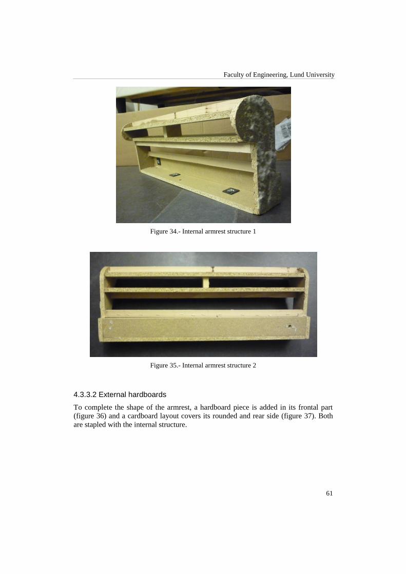
Faculty of Engineering, Lund University
61
Figure 34.- Internal armrest structure 1
Figure 35.- Internal armrest structure 2
4.3.3.2 External hardboards
To complete the shape of the armrest, a hardboard piece is added in its frontal part
(figure 36) and a cardboard layout covers its rounded and rear side (figure 37). Both
are stapled with the internal structure.

Current Design Analysis
62
Figure 36.- Front armrest view
Figure 37.- Armrest cardboard and detail of its stapled
4.3.3.3 Links
In this case, the importance of the union between the armrest and the base frame is
not such as big as in the backrest, because the forces that this element has to support
are lower. There are two holes in the bottom that join the armrest to the base frame
through a screw plus a nut. It is also linked with the backrest with the same system
(but only with one screw) giving the whole sofa structure even more stiffness and
stability.
Figure 38.- Armrest links

Faculty of Engineering, Lund University
63
4.3.3.4 Problems and challenges
The armrest represents one of the most difficult parts for automation as this piece
seems to be conceived to facilitate manual assembly.
As a first thought, we suggest changing the order of assembly of each piece integrat-
ing this part. It would be easier for a robot to start assembling from a defined base. In
this case, one will be tempted to take both lateral board planks and the plank in the
base of the structure as a base to start building the piece. However, it is important to
remind that all the internal supports are fixed to these pieces and they work like an
enclosure, giving to the piece its particular shape and robustness. Thus, we think,
then, about using the outer frontal board plank together with one of the lateral board
planks as the construction base. These two pieces can be fixed together by gluing and
stapling. Thereupon, the base plank could be also placed, glued and stapled to the
basic structure. From this point, could be placed each of the other internal supports in
their corresponding position. Once all the internal supports are located, glued, stapled
and reinforced, the remaining lateral plank would be fixed to the whole structure.
However, there might be strong difficulties when locating pieces that are supposed to
be centered without contact with the outer frontal plank. Hence, it would be advisable
to change the internal design of the armrest in order to allow all pieces to be con-
nected to this basic structure, without compromising its stability, shape or stiffness.
Thus far, automating the assembly process for the armrest is, as we consider, reason-
able and feasible. However, finishing the entire piece would have some difficulties.
As described before, the armrest has a cardboard piece in the inner part, which per-
mits covering the rest of the piece that was left without a cover and would help in the
process of upholstering it. This cardboard cover is difficult to manipulate and to place
in position automatically. It can be done, of course, by adapting the system with spe-
cial tools that permits to hold the cardboard, attach it to the structure and then glue it
and staple it. This solution would increase the complexity of the system as well as the
costs. To meet this challenge, we suggest integrating the manual process to the auto-
mation assembly by having a final stage for the assembly of the armrest where finish-
ing the piece can be done manually. It can be done with conveyors where all the semi-
finished pieces will arrive to a manual station to be finished by a worker.
4.3.4 Upholstery
Once the base frame, the backrest or the armrests have been assembled, the next step
is adding to each one the upholstery. This operation consists basically in adding foam
plus wadding layer to the parts of the sofa that will contact with the people sitting on
it and at least one more lining to cover the whole part. Below is described the uphols-
tery applied to every part of the sofa.

Current Design Analysis
64
4.3.4.1 Base frame
In the base frame, only the front, back and lateral planks have a glued foam layer.
Then each of these planks as well as the armrest bases is covered with a single lining.
Each of these pieces are tightened, sewed with each other and finally stapled in the
bottom and internal part of the base frame. Two extra layers of lining are added to
cover the spring mattress. The first one is stapled with the back plank (under the foam
layer) and the central beam. The second one is sewed with the pieces of lining that
cover the back plank and armrest bases, and stapled to the central beam as the first
one. In the next pictures the different linings of the base frame are shown.
Figure 39.- Complete upholstery
Figure 40.- Detail of the stapled
4.3.4.2 Backrest
In the backrest, only the rear part is covered with foam, as the frontal part is later
covered by cushions. Two pieces of foam are glued. One covers the rear side and an
additional one gives extra softness to the top of this part. To finish the upholstery for
this part, lining is first sewed with its shape, placed covering the backrest, and stapled
while it is tightened to remove existing wrinkles.

Faculty of Engineering, Lund University
65
Figure 41.- Backrest after the upholstery
4.3.4.3 Armrest
The upholstery operation in each armrest starts with the glued of four foam parts cov-
ering the whole part except the bottom. One piece of foam covers the frontal part,
another one the rounded and rear part and finally we have two pieces covering every
side.
Figure 42.- Foam layer
Then, a wadding layer is glued to the previous foam, covering the whole armrest ex-
cept the bottom and sides.
Figure 43.- Wadding

Current Design Analysis
66
Finally, a piece of lining previously sewed is placed covering the armrest and stapled
in the bottom, giving it the rounded shape.
4.3.4.4 Problems and challenges
As it is in the assembly part described above, the main problem and at the same time
challenge that we face when automating the upholstery operation of the foam, wad-
ding or lining is its placement prior to the stapling or gluing. To follow the same
structure than before and attending that each part of the sofa have different derivate
problems, each part is described separately.
4.3.4.4.1 Base frame
The upholstery in the base frame can be separated in pieces that correspond to each of
its components. For example, we have one piece of foam and one of lining per each
plank. Consequently, a conservative solution could be creating an automated process
to add the upholstery to each piece individually. However, this way implies a change
in the assembly flow as the upholstery would be applied before the frame is complete-
ly assembled.
The four planks as well as the armrest bases have a similar shape, so a single fixture
can be used to hold the piece and add first a glued layer of foam and then the stapled
lining. The existence of a gluing robot already working in the process can be really
helpful as the stapling operation of the lining is a similar process. For this stapling
operation, the piece of lining would be first placed in the fixture, then the plank and
then a robot can easily staple it, helped by some clamps holding the lining in the cor-
rect position.
Adding the lining that covers the spring mattress in the same way is more difficult
because it is not a single part of the sofa. Moreover, it is covered by two layers of
lining. However, if we apply the idea presented above in section 4.3.1.8, consisting on
making this part as a single preassembled part, the same procedure as with the planks
could be applied. Nevertheless, if we decide to keep the same structure design we can
add a layer of lining covering the whole base frame avoiding the stapling in the cen-
tral beam.
In addition to this, if we get an increase of quality in the stapling of the lining pieces it
would be possible to remove the sewing of them together. Therefore, the hardest op-
eration to automate would be removed from the process.
On the other hand, a less conservative option would be change the materials used to
fix the upholstery. Instead of using glue and staples it is possible to use thermal-
sensitive adhesives. In that way, the upholstery operation would be simplified to a
placement operation. Then, just by warming the adhesive, the upholstery would be-
come fixed to its corresponding part.

Faculty of Engineering, Lund University
67
Another possibility for the lining would be use a different material. There are some
kinds of modern fabric that are thermal-sensitive and have the property of acquiring
the shape of the object they are covering when they are warmed up. If we use this
solution, not only the gluing and stapling operations are removed, but even the
placement of the lining is simplified as the precision needed decreases considerably
because the wrinkles disappear from the thermal-material automatically.
4.3.4.4.2 Backrest
In this case, the part that is covered with foam corresponds to the rear hardboard. So
the same procedure of adding the foam to a single piece explained in the previous
section can be used. The hardboard would be hold by a fixture and would be glued in
order to add then the foam.
To apply the second layer of foam on the top of the backrest, it has to be completely
assembled. Then, using the same fixture system, the second piece of foam can be
attached. Nevertheless, in this scenario the operation flow would need to be rede-
signed because we would add foam first to a single part and then to the assembled
backrest.
The addition of the external lining would be in this part difficult to automate. The
existence of the bottom hole and the form of the whole structure complicates the cor-
rect placement of the lining. For this reason, we think that the best option would be
adopt a thermal-sensitive fabric as proposed before for the base frame. Otherwise, we
will not be able nor to beat the manual manufacturing time nor to get acceptable
costs, so would be better to continue with manual upholstering.
4.3.4.4.3 Armrest
The challenge in this part is its rounded shape. As stated in the two previous sections,
the most conservative and simplest way to add the foam and the wadding would be
individually to every external part prior to the assembly. In that way we avoid the
uncomfortable form of the armrest by attaching the materials to flat pieces. This lets
us again use the same fixture system described before.
At the time of adding the external lining, we have to face again the same problem
found in the backrest, its irregular shape. For this reason we recommend once more to
adopt a thermal-sensitive fabric in order to evade the current difficulties as well as the
stapling and sewing operations, or keep manual upholstering.
4.3.5 Cushions
The manufacturing of the cushions is split in two parts, first the filling and second the
stitching. In the filling process, an operator fits the cushion in the filler machine to fill
it with polyester fiber. The filled cushions are weighed in order to know if they have
the correct amount of fiber. Then, another operator stitches the cushions to close the

Current Design Analysis
68
filling hole and give them the final shape. Pictures below show the current filling and
stitching processes.
Figure 44.- Filling of cushions
Figure 45.- Stitching
There are two different cushions. On one hand, we have the ones that have a single
fiber compartment. On the other hand, backrest cushions have two compartments to
prevent all the fiber falling down over time. The division between both compartments
is made with a piece of lining stitched between both compartments. At the same time,
this piece of lining confers the cushions its final body.
4.3.5.1 Problems and challenges
As said before, the filling of the cushions and its stitched are the two main operations.
For the automation of the first one, several machinery options are available. Lots of
Chinese and Indian (traditional countries with a deep knowledge in textile manufac-
turing) companies are offering systems that automatically fulfill the cushions [15]
.

Faculty of Engineering, Lund University
69
They consist in a feeder for the cushions, another one for the polyester fiber and a
weighing system to ensure that the correct amount of fiber is used in each cushion. In
a quick view to some of these systems we have seen that a common throughput is
from 150 to 200 kg of fiber filled per hour.
The stitching operation is the most difficult operation for the cushions. If the current
process stitches the cushions after having filled them with fibers, it is difficult to per-
form an automatic stitched on a soft material to give the cushions their final shape.
Nevertheless, the current design of Ektorp sofa cushions seems to be stitched prior to
the filling. If it is done that way, one can even fill both compartments in double cu-
shions at the same time as the filling machines usually provide two heads. Finally, to
close the filling holes the same kind of machinery can be used.
The final packing operation of the cushions can be easily automated as it only con-
sists on placing them in plastic bags.
To sum up, it could be considered that although the automation of this process can
increase its speed and quality, it would not be that worth because the current time (4‟8
minutes) is short compared to the rest of the sofa.
4.3.6 Final remarks
In the Ektorp Sofa assembly, one of the most difficult parts to automate lies in the
base frame. The spring system requires special attention as it is one of the most com-
plicated structures within the Sofa. If it is desired to be totally automated, it is advisa-
ble to change its design in order to make easier, less specialized and in consequence,
less expensive.
The main challenge in the backrest, in common with the armrest, is the assembly of
the internal structure. The problem lies in a correct placement of the different pieces
forming this structure in order that the stapling and gluing operations can be automat-
ically done in the easiest way. Thus, we think that the best solution is redesigning it or
installing a fixture that facilitates the configuration of those operations.
The armrest represents another important challenge when automating. Due to its sev-
eral pieces and its conceived design for manual assembly, it happens to be challeng-
ing to accomplish the entire manufacture of this part automatically. We suggest focus-
ing on changing completely the design of this part in order to make it suitable for an
automatic assembly. There are possibilities to integrate a few manual processes to the
automatic system.
The addition of foam and wadding can be simplified in most cases if it is done to
single flat pieces. On the other hand, we recommend the use of thermal-sensitive fa-
brics if it is possible as they grant the possibility to automate a process that otherwise
would be almost impossible in some parts without high expenditures. There is also
specialized machinery for lining stapling that can be adapted to this assembly process.
For the production of the cushions, the purchase of automatic filling machinery could
reduce considerably its manufacturing time by the time the quality is increased. The

Current Design Analysis
70
high throughput of filling machines, in addition to the accuracy of their weighing
systems, helps in this point.
4.3.7 Other recommendations and suggestions
As it is desired to have a high quality standard and minimizing the assembly time, it
would be advisable to include an assembly check control, for example, a vision sys-
tem.
There should be quality check points between each work station to guarantee the ful-
fillment of the specifications and to control the flow of the process.
There should be a compromise between design, price and ease for automation. For
that reason we suggest analyzing all the alternatives regarding changes in design and
manual procedure within the automatic assembly. Although robots can be pro-
grammed and design for fulfill almost any specific industrial task, there are still some
actions that are done more easily and faster by a human worker.
When possible, the automation process should be as much general as possible.
Achieving a high level of standardization, the same assembly process could be
adapted to the production of different sofa models and similar furniture.

Faculty of Engineering, Lund University
71
4.4 Visit to the Factory
The aim of this section is to give a short summary of the most relevant information,
ideas and conclusions that we got during the visit to Company A and Company B in
March.
The section is divided in three parts describing the visit to Company A first, then
Company B and finally some conclusions. The Company A section includes some
general information about the company, a description of a responsible engineer´s
work and work being developed in the design offices.
4.4.1 Company A
Company A is said to be the second most important IKEA supplier after Swedwood,
IKEA‟s wood supplier. According to the responsible engineer´s presentation, the
current throughput is about 700.000 pieces/year (usually this number is given in
seats/year). In this case, piece means a part of the sofa, in other words, the base frame,
the armrest or the backrest. Therefore, we understand that four pieces means one sofa.
Another number stated during the presentation was 16.000 pieces/week. We guess
that this is the max throughput achievable with the current production lines.
The remaining 5% in production is dedicated to Company A sofas‟ own production.
They currently have five shops where they sell their own sofa designs and comple-
ments.
The company has about 20 machine suppliers and some material suppliers. About that
second group, it is worth to remark that one of them is responsible for the production
of armrests. They receive the armrests assembled and the only missing part is the
upholstery. Nevertheless, at the moment of the visit, the outsourcing agreement was
going to be over in the 2 weeks. From that moment on, Company A was going to start
producing the whole armrests by themselves.
It was given to us all the basic information about the company. In addition, it was
shown to us the factory facilities as well as answered most of our questions. After the
presentation and meeting with some of the persons in charge of the company, we can
ensure they were definitely open-minded to machines, robots and automation in gen-
eral. The company has some staff working to improve and automate the current sofa
assembly lines. Here below is described the information we got about the new project
they are currently developing.
4.4.1.1 Improving and automating project
At the time, their project consists in automating parts of the assembly process keeping
the same sofa structure, same pieces and same flow. In general, what we saw in the
factory is that the idea relies on the semi-automation, in a similar approach as in the
gluing department where robots glue the pieces whereas co-workers place the foam.

Current Design Analysis
72
4.4.1.1.1 Current automated processes
4.4.1.1.1.1 Gluing department
Three gluing robots are already working in the gluing department, gluing parts of the
sofa before the foam is placed. However, one of the robots was not in operation as
they were trying to solve problems to keep the glue density in gluing guns. Three
months have been spent in order to set up this semi-automated station.
The robots are split in 2 lines as shown in the diagram in figure 46. There is one robot
per each line and another one shared by both. The process starts on the top of the
diagram where two employees place the pieces that are going to be glued into the
fixtures on a conveyor belt (there can be two backrests or four armrests). The first
robot glues frontal and rear areas of the pieces and then four workers add foam to the
glued parts. Subsequently, if the parts being glued happen to be armrests, the shared
robot supplied glue again, this time in order to place the lateral foam and the wadding
(done by the last two co-workers).
Figure 46.- Gluing station diagram
The process is still not optimized as we realized that the robots are idle too much
time.
4.4.1.1.1.2 Conveyor system
To transport finished parts along a single station a conveyor system is installed in
each working line. The transport operation between stations is carried out manually.

Faculty of Engineering, Lund University
73
4.4.1.1.1.3 Sofa packaging
The final packaging of the assembled sofas can be done automatically. Nevertheless,
the placement of protection cardboard pieces has to be done manually previous to the
plastic film packaging.
Due to some changes in the process, the automatic line was not working during the
visit and all the packaging was manual.
The automated packaging is expensive but really fast and has better quality than the
manual one.
4.4.1.1.1.4 Automatic rapid clip installation
As opposite to what we expected, the rapid clips installation is automated for effi-
ciency, precision and security reasons.
The system is formed by a co-worker feeding the joist where the clips are stapled and
a vibrating container that supplies clips in a proper orientation through a rail system.
The distances between clips along the joists can be adjusted with a millimeter preci-
sion. A stapling machine staples twice each clip fed by the vibrating container. The
co-worker is responsible of feeding joists and picking up finished pieces in two rapid
clip lines.
4.4.1.1.2 Future automation plans
The automation plans for the near future, included in the project developed by the
company, are stated below.
4.4.1.1.2.1 Inter-station transport
The transportation between stations is currently a subproject in progress. This will
give more autonomy to the line and avoid the costs and part of the time consumed
when done manually. On the other hand, more synchronization will be needed be-
tween the different stations within the whole assembly process.
4.4.1.1.2.2 Cushion gluing
A line for gluing the cushions would be ready in April.

Current Design Analysis
74
4.4.1.1.2.3 Purchased robots
Four assembly robots had been ordered. They were divided in two groups. Group one
would be used to feed elements to the line executing pick & place operations. Group
two would be used in stapling operations.
The estimated throughput in the semi-automated line where these four robots would
be installed was estimated to be 450.000 pieces/year.
The chosen brand was Kawasaki because it is the one offering the best quotation in
the market.
In case of changing the materials used in the sofa or modifying the process, the in-
vestment was protected because the purchased robots and feeders are general enough
to be updated and used in the redesigned operations. For example, if we move to a
metal base frame the stapling robots can be used as welding robots by changing the
tool.
4.4.1.1.3 Miscellaneous
Some other topics that appeared during the meeting are described below.
The idea of doing the armrest in one piece has already been tested by Company A and
it was rejected. At least with the plastic/s used during the trial the armrest become too
expensive and according to them it did not make up the reduction of complexity in
this part.
About moving to a different material to produce the sofa, different opinions where
stated. Related to a metal frame, although it will probably increase the final weight of
the sofa, they consider that the tolerance problems that appear when working with
wood would be avoided. Different temperatures and humidity levels do not modify
the shape or measurements like in wood. Thus, repeatability will be granted. Moreo-
ver, even if the metal is heavier than the wood, its stiffness and higher resistance
combined with a good welding allow reducing the volume of the pieces and conse-
quently reducing the weight of this solution.
The use of injected plastic will not probably increase the weight but will increment
the price. Nevertheless, every injected plastic piece can include the attached pieces
that would have if we keep using wood, so the number of pieces would be reduced.
As a final remark about the visit to the factory we would like to comment that imple-
mented security should be incremented.
All employees in the factory must use security shoes, appropriate gloves and glasses
(currently used). Moreover, employees who operate cutting or sanding wood must use
protective mask to protect themselves from sawdust. We also realized that, for exam-
ple, employees cutting lining with automatic machines have their hands exposed dur-
ing the operation and do not use any kind of gloves.
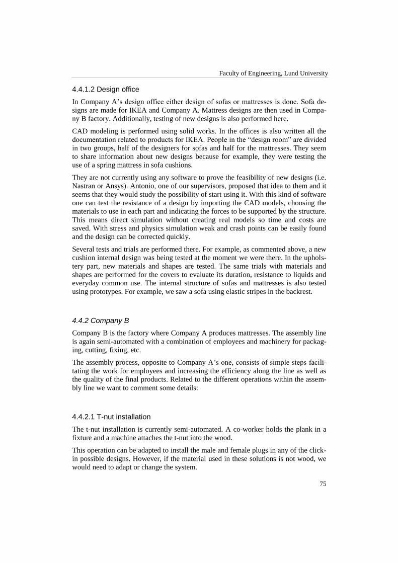
Faculty of Engineering, Lund University
75
4.4.1.2 Design office
In Company A‟s design office either design of sofas or mattresses is done. Sofa de-
signs are made for IKEA and Company A. Mattress designs are then used in Compa-
ny B factory. Additionally, testing of new designs is also performed here.
CAD modeling is performed using solid works. In the offices is also written all the
documentation related to products for IKEA. People in the “design room” are divided
in two groups, half of the designers for sofas and half for the mattresses. They seem
to share information about new designs because for example, they were testing the
use of a spring mattress in sofa cushions.
They are not currently using any software to prove the feasibility of new designs (i.e.
Nastran or Ansys). Antonio, one of our supervisors, proposed that idea to them and it
seems that they would study the possibility of start using it. With this kind of software
one can test the resistance of a design by importing the CAD models, choosing the
materials to use in each part and indicating the forces to be supported by the structure.
This means direct simulation without creating real models so time and costs are
saved. With stress and physics simulation weak and crash points can be easily found
and the design can be corrected quickly.
Several tests and trials are performed there. For example, as commented above, a new
cushion internal design was being tested at the moment we were there. In the uphols-
tery part, new materials and shapes are tested. The same trials with materials and
shapes are performed for the covers to evaluate its duration, resistance to liquids and
everyday common use. The internal structure of sofas and mattresses is also tested
using prototypes. For example, we saw a sofa using elastic stripes in the backrest.
4.4.2 Company B
Company B is the factory where Company A produces mattresses. The assembly line
is again semi-automated with a combination of employees and machinery for packag-
ing, cutting, fixing, etc.
The assembly process, opposite to Company A‟s one, consists of simple steps facili-
tating the work for employees and increasing the efficiency along the line as well as
the quality of the final products. Related to the different operations within the assem-
bly line we want to comment some details:
4.4.2.1 T-nut installation
The t-nut installation is currently semi-automated. A co-worker holds the plank in a
fixture and a machine attaches the t-nut into the wood.
This operation can be adapted to install the male and female plugs in any of the click-
in possible designs. However, if the material used in these solutions is not wood, we
would need to adapt or change the system.

Current Design Analysis
76
4.4.2.2 Mattress structure shape
The shape in the ends of mattress' external planks (see figure 47), fitting with each
other, avoids the use of glue while building the main internal mattress structure.
Moreover, the use of nails instead of staples gives more resistance to the structure.
Although the resistance could seem to be reduced when no glue is used, they told us
that it has already been tested with satisfactory results.
Figure 47.- Fitting ends
The same shape at the ends of the pieces, together with nailing instead of gluing and
stapling, can be applied to the current design of the sofas unless we change the ma-
terial.
4.4.2.3 Fixture
The assembly of the internal mattress structure commented above is assisted by a
special pushing fixture, shown in figure 48, which does two functions, first pushing
the planks to join them and then holding the structure for nailing and attaching other
pieces. Two co-workers place the planks (without worrying about doing it perfectly)
in the fixture and then, by pressing a button, the fixture pushes the planks to join and
to hold them together.
This fixture can also be used in the sofa base frame assembly to help the co-workers
in the manual work.

Faculty of Engineering, Lund University
77
Figure 48.- Pushing fixture. Arrows show the direction of movement of the parts
4.4.2.4 Tightening machine
Once the internal structure is assembled and the mattress and its cover is installed
within the structure, there is a machine that press down the whole piece to facilitate
the employees stapling the cover. That way ensures that when the machine releases
the piece the cover is completely tightened. Nevertheless, we realized that because of
the quality of the speed of the stapling operation sometimes the staples are not cor-
rectly placed. To increase this quality an automatic stapling system can be used.
4.4.3 Visit conclusions
As we already knew, the current sofa structure has too many pieces that make diffi-
cult and slow down its assembly.
To gain more efficiency and reduce assembly times it is necessary to split the current
assembly stages to simple and faster operations. Currently the assembly of the base
frame or the backrest or the armrests is done by one co-worker carrying with all the
different steps and operations. The result would be similar to the line in the gluing
department where the addition of the foam to the corresponding sofa parts is carried
on in several simple steps.
Some of the current automated operations executed in the mattress factory and de-
scribed above can be adapted and used in the sofa assembly.
Security must be taken into account while developing our solutions.
The future existence of the four ordered robots can be taken into account when de-
signing new automated solutions.

Current Design Analysis
78
4.5 Matrix Summary
In order to summarize all the analysis done to the current sofa design we have created
a set of tables describing its most important characteristics. They show the number of
parts, the materials used and their corresponding volumes, the assembly times and an
estimation of the final price in terms of materials (work force cost is not taken into
account).
With this information we have the basis to compare and evaluate the quality and
goodness of our new designs.
Notice that, in this section, when we talk about parts we mean either the base frame or
the backrest or the armrests. Note also that one sofa is composed by one base frame,
one backrest and two armrests.
4.5.1 Number of pieces
Table 16 shows the number of pieces that compound each of the three different parts
of the sofa (base frame, backrest and armrest) attending the material they are made of.
The first column in the left (blue) lists the materials. The three middle columns show
the number of pieces per part and material with the total number for each in the bot-
tom row. Finally, the last column in the right (orange) states the total number of piec-
es for each material and in its bottom the total amount of pieces in the sofa (157 piec-
es for the entire sofa).
Mind nor the number of staples nor the number of nails are considered in this first
table.
Table 16.- Number of pieces per material and part
Material Base frame Backrest Armrest Total number
Solid wood 10 8 4 26
Particle board 6 3 6 21
Plywood 4 0 0 4
Hardboard 0 2 1 4
Cardboard 0 0 1 2
Nozag 12 0 0 12
Plastic 24 2 0 26
Steel 11 12 3 29
Foam 5 3 4 16
Wadding 0 0 1 2
Lining 8 1 3 15
80 31 23 157

Faculty of Engineering, Lund University
79
4.5.2 Material usage
This second table summarizes the quantity of each material used in the current sofa
design.
As before, the first column (in blue) shows the different materials with their measur-
ing units in brackets. The next three orange columns show the quantity of each ma-
terial used per part in the specified measuring units. The fifth column (green) has the
quantity of each material in the entire sofa. The last but one states the price per unit of
each material5 in euros and the last column (red) the cost per material within the sofa.
Table 17.- Material quantities and prices
Material Base frame Backrest Armrest Quantity Price/unit
(€)
Total price
(€)
Solid wood (m3) 0,0107 0,0034 0,0012 0,0166 379,7924 6,3178
Particle board (m3) 0,0133 0,0020 0,0060 0,0273 257,7346 7,0359
Plywood (m3) 0,0017 0 0 0,0017 685,0653 1,1687
Hardboard (m3) 0 0,0040 0,0005 0,0049 340,2200 1,6715
Cardboard (m3) 0 0 0,0006 0,0012 0,1285 0,0002
Nozag (pieces) 12 0 0 12 0,0154 0,1850
Plastic (pieces) 24 2 0 26 0,2827 7,3492
Staples (pieces) 550 360 340 1590 0,0002 0,2846
Steel (kg) 0,4567 1,4520 0,0178 1,9444 1,2334 2,3983
Foam (kg) 0,5205 0,4263 0,3919 1,7305 0,9508 1,6453
Wadding (m2) 0 0,0000 0,5751 1,1502 0,3341 0,3842
Lining (m2) 2,8145 1,3492 0,6994 5,5624 0,1182 0,6575
4.5.3 Manufacturing times
This table shows the current manufacturing times measured during the visit to Com-
pany A in March.
The assembly times include handling, insertion and the necessary gluing, stapling or
screwing operations to build each part. Upholstery times comprise handling the foam,
wading or lining and their corresponding gluing, stapling or sewing operations as
well.
5 Material prices provided by Ikea.

Current Design Analysis
80
Table 18.- Assembly times per part
Times Base frame Backrest Armrest Total
Assembly time (s) 300 345 225 18‟ 15”
Upholstery time (s) 425 205 185 14‟ 35”
12‟ 05” 8‟ 20” 13‟ 40”
4.5.4 Final results
Attending the data from tables 16 and 17, these are the final values for the current
manufacturing process regarding time and price. The total manufacturing time is 34
minutes and 55 seconds. The total material price is 29‟10 euros.
Table 18.- Total manufacturing time and material price
Total time 34‟ 55”
Total price 29,10 €€

81
5 Improvements
Having a clear image of the current sofa design after the wide analysis performed in
chapter 4, in this chapter some possible improvements are presented. Following the
recommendations and attending the challenges that came to light we discuss possible
solutions in terms of redesign of some parts and machinery that can be used for its
automation.
The first section is focused on the modification, redesign or removal of single pieces
of the sofa. Following sections change the approach, and concentrates on the redesign
of the entire base frame while keeping the same final shape and functionality. To end
up with this chapter, last section gives a comparison to expose the benefits and prob-
lems when applying the suggested modifications.
5.1 Modifying the Current Design
5.1.1 Removing internal supports
A high number of planks in the base frame contain several solid wood joists that are
giving extra stiffness to this structure. Their installation is certainly time consuming
and their existence complicates the design of the current sofa as well as its assembly
process.
After our analysis, we have concluded that the need of some of these supports is un-
certain. To put an example, we can take a look to the small supports attached to the
lateral planks (figure 49).
Figure 49.- Supports in the lateral planks
Their function is showing the place where the main joist is installed. However, the
main joist vertical forces are supported by the screws fixing it to the lateral planks.
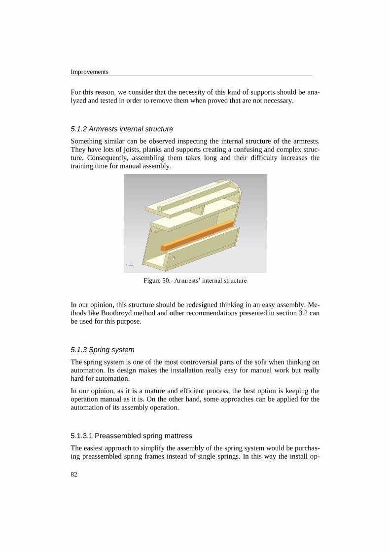
Improvements
82
For this reason, we consider that the necessity of this kind of supports should be ana-
lyzed and tested in order to remove them when proved that are not necessary.
5.1.2 Armrests internal structure
Something similar can be observed inspecting the internal structure of the armrests.
They have lots of joists, planks and supports creating a confusing and complex struc-
ture. Consequently, assembling them takes long and their difficulty increases the
training time for manual assembly.
Figure 50.- Armrests‟ internal structure
In our opinion, this structure should be redesigned thinking in an easy assembly. Me-
thods like Boothroyd method and other recommendations presented in section 3.2 can
be used for this purpose.
5.1.3 Spring system
The spring system is one of the most controversial parts of the sofa when thinking on
automation. Its design makes the installation really easy for manual work but really
hard for automation.
In our opinion, as it is a mature and efficient process, the best option is keeping the
operation manual as it is. On the other hand, some approaches can be applied for the
automation of its assembly operation.
5.1.3.1 Preassembled spring mattress
The easiest approach to simplify the assembly of the spring system would be purchas-
ing preassembled spring frames instead of single springs. In this way the install op-

Faculty of Engineering, Lund University
83
eration would be reduced to a single pick and place operation of the entire frame fol-
lowed by a second operation to fasten it to the base frame structure.
Figure 51.- Spring frame
Although we are simplifying the installation of the spring system, with this method
we are shifting the difficulty of building the spring frame to the supplier. Thus, the
price will be increased but, on the other hand, the assembly time is reduced and prob-
ably the quality and durability of the spring mattress would be increased.
It is also possible to use a preassembled frame for each seat in the sofa. This is the
approach followed for example in car seats.
5.1.3.2 Redesigning rapid clips
If we want to keep using the same springs, another option is changing the rapid clips
to facilitate attaching the springs. In the current design, the springs are placed follow-
ing a horizontal from outside movement. This movement is difficult to imitate auto-
matically as it is necessary to place first one end of the spring and pull the other end
to fasten it to the opposite clip.
Attending this challenge, we propose redesigning the clip to enable a vertical from
above insertion. A possible redesign result is shown in the next figure.
Figure 52.- Rapid clip redesign

Improvements
84
Another possible redesign for the rapid clips could be joining them all together in a
couple of clip sticks (see figure 53). The current or the new clip design above could
be used as the aim of this idea is facilitating the installation of the clips in the main
joist and the frontal plank.
Figure 53.- Clip stick
The current clip attaching operation puts the clips one by one. With a stick we just
need to place and fasten one element. However, the current operation is automated
and it is really fast.
5.1.3.3 Feeding springs
Once allowed a vertical from above spring insertion, another important challenge is
their feeding. The springs are easily tangled with each other when they are manipu-
lated. Hence, a feeder is necessary in order to automatically supply them.
The figure below shows a possible feeder. This feeder would receive packs of springs
and would supply them one by one on the top. It would push the springs from the
bottom until one overtakes the upper limits.
Figure 54.- Feeder sketch
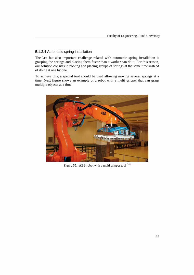
Faculty of Engineering, Lund University
85
5.1.3.4 Automatic spring installation
The last but also important challenge related with automatic spring installation is
grasping the springs and placing them faster than a worker can do it. For this reason,
our solution consists in picking and placing groups of springs at the same time instead
of doing it one by one.
To achieve this, a special tool should be used allowing moving several springs at a
time. Next figure shows an example of a robot with a multi gripper that can grasp
multiple objects at a time.
Figure 55.- ABB robot with a multi gripper tool [17]

Improvements
86
5.2 Redesigning the Base Frame
Two of the biggest problems that we have found in the current design of the sofa are
the large number of different pieces that are necessary to assemble the basic structure
of the base frame as well as the several operations of pick and place, gluing and stapl-
ing on each of them. Also, the spring system is a difficult part for assembly, as stated
before, because of the positioning and fastening of the springs along the clips in the
base frame.
The main advantage of the new designs presented on this section is the removal of
stapling and gluing operations. Therefore, the necessary time to build the base frame
is considerably reduced by the time we avoid using glue and specially a high amount
of staples. Moreover, the assembly system is definitely simplified as the number of
pieces is highly reduced.
5.2.1 Push-in design
This design is based in a place and push system where all main parts of the base
frame can be easily attached together without glue or staples for reinforcement.
Some of the biggest advantages of this design are the ease for joining each part of the
base frame and also the reduction in the amount of pieces and, consequently, opera-
tions.
On the other hand, given this type of design, we consider that using wood would not
be advisable in terms of tolerances and mechanical resistivity. Thus, it would be ne-
cessary to use another kind of material to ensure durability and strength within the
sofa.
For avoiding those problems in the current design, increasing the repeatability and
facilitating the automation, we propose now a base frame with the following characte-
ristics:
The rear plank, the main joist and the frontal plank with the same design.
Planks formed by single pieces, without internal supports.
Same leg‟s bases for the four corners (currently the rear leg‟s bases are longer
than the frontal ones).
Same armrest‟s bases.
Assembly done manually with ease and low time consuming.
For achieving the desired characteristics mentioned above, we propose a plug-in sys-
tem for assembling the basic structure. This concept was inspired by shelf connection.
The design is described here below.

Faculty of Engineering, Lund University
87
5.2.1.1 Frontal plank, rear plank and main joist
Either the frontal and rear planks or main joist would have, on both edges, a
T-shaped form that would be the male part of the push structure. This special
shape will fit inside of each lateral structure.
Same design for all these pieces.
All the extra joist and support have been removed. The new profile considers
a single piece.
At the high view, we can observe that they have a little shape for remaining
the same structure of the current sofa.
Those simple connections ensure stability and resistance for all forces applied
over these parts that are orientated either from the top to the bottom or out-
wards.
It would be necessary to add the fittings of the spring system in the frontal
plank and main joist.
Figure 56 and 57 show different views of this part.
Figure 56.- Top view of the frontal/rear plank and main joist.
Figure 57.- Side view of the frontal/rear plank and main joist.
5.2.1.2 Lateral structures
The profile of the lateral planks is formed by several holds in the structure al-
lowing either the frontal and rear planks or the main joist to get inside of
them.
Identical left and right lateral profiles.

Improvements
88
They have T-shaped holds located at each edge of the structure and closer to
the rear part of the structure.
Along the structure, there are some holds to push, inside of them, the ar-
mrests. Taking profit of this since we would decrease the weight of the parts
and we would use less material to build them.
All the small supports were removed remaining one single piece.
Figure 58.- Side and Bottom view of the lateral profile.
Figure 59.- Top view of the lateral structure.
5.2.1.3 Armrest’s bases
The holes for locating the screws of the armrests are placed equidistantly to
guarantee identical left and right pieces.
No staples or glue to attach to the planks.
The new profile of the armrest´s bases was designed in order to remain the
same kind of peaces for left and right sides.
The protruding parts that we can observe in the figures below were designed
to be pushing inside the corresponding lateral structures.
The design was thought for resisting the applied horizontal and vertical
forces.

Faculty of Engineering, Lund University
89
Figure 60.- Bottom view of the armrest plank.
Figure 61.- Top view of the armrest plank.
5.2.1.4 Leg’s bases
Identical 4 leg‟s bases.
The hole is located in the same place that it was in the old design. It can be
changed according to the stability of the base frame.
Figure 62.-Different views of the leg´s bases.
5.2.2 Click-in way
In this second design, changing the point of view from the current design, we think
that it would be better to redesign the whole frame using a “click-in” method to join
all parts which make up the sofa.

Improvements
90
We need to create a kind of connection between each part of the frame. We suggest
attaching two different kinds of pieces to each plank. The different pieces consist in
“male” and “female” like in a common plug system. From here, we will call them
“male plug” and “female plug”. These pieces, together with the connection between
them, are shown below.
About the new connections, the possibility or necessity of detaching two parts once
they are joined should be considered. The easiest option if we want to keep the plug
in system as easy as possible is disallowing the possibility of unplugging it once con-
nected. Nevertheless, in this case you must ensure that it is not permitted to connect
two pieces in the incorrect position. For this reason the shape of the male - female
union needs to grant it. On the other hand, we can add a lock to the plug-in system
with a simple key (i.e. a common Allen wrench) in order to unlock the system and
disassemble two pieces. However, this solution adds extra complexity and conse-
quently extra cost.
5.2.2.1 Male plugs
This piece has been designed in order to be introduced into the female plug. It is im-
portant to know once the different plugs, either male or female, are attached one to
each other, it will be impossible to disjoin them for our solution. To avoid this kind of
problems, the top of the male plug has been designed in order to have a unique way to
join the different planks.
The last detail, within this stage, has been to solve the coupling between the pieces.
As a common locker system, we have made a cut with a specific angle where the
male plug will be impossible to extract once it is inlaid into the female plug.
Figure 63.- Different views of the male plug.
5.2.2.2 Female plugs
The other piece of the click-in system is the female plug. It has been designed in order
to embed in it the male plug. As it is shown in the figure below, the hole has a specif-
ic half-circumference to allow the entry by this unique way.

Faculty of Engineering, Lund University
91
Figure 64.- Different views of the female plug.
The little piece inside the hole is responsible of keeping the male plug into the female
plug once they are attached. If this piece is pushed in one direction (entry), it folds the
male plug while going in. However, folding it in opposite direction is impossible.
5.2.2.3 Assembly process between plugs
Regarding the way that the click-in system works, below, some illustrative figures
explaining the joining process between the different parts of the sofa are shown.
Figure 65.- Joining process between the plugs.

Improvements
92
The plug male push the mechanism inside the female plug folding the little piece.
Figure 66.- Male plug getting into the corresponding female.
The corresponding planks are attached by the click-in system.
Figure 67.- Two planks attached.
The idea of repeatability in the frame is, in general, quite important. During the as-
sembly stage, higher similarities between parts of the sofa would ensure us a better
automated production and assemble process.
Nevertheless, although we are taking profit of the similarities between the different
parts to improve the repeatability and simplify its production, we are adding a plug in
system that did not exist before. These connection mechanisms have to be installed in
each plank previous to the assembly of the base frame, so we are shifting part of the
complexity to the production process whereas the assembly process is simplified.
Talking about the stiffness of the whole base frame, it could be necessary to increase
a bit the depth of the planks in order to keep the same resistance. The width and depth

Faculty of Engineering, Lund University
93
of the click-in system has to be studied and consequently, maybe the planks have to
be adapted to it. Moreover, the position of these union pieces in the planks needs to
be correct as well as the way they are attached to them. Otherwise, the whole struc-
ture could be threatened.
For the reasons presented previously, we suggest the following planks and pieces
forming the whole base frame. For each piece, the reasons, purposes and main
changes introduced in comparison with the current design are explained. The pictures
show the design and the locations of the click-in systems in each piece.
5.2.2.4 Frontal and rear planks
In this case we have achieved the goal of having the same structure in both
planks so they can be produced in the same way. The only difference between
them is that the frontal will have the fitting structure to attach the springs.
Four female plugs have to be installed in the extremes of each plank. Two at-
taching the corresponding armrest bases with them and the two remaining
plugs placed on the bottom for the connection between these planks and the
leg bases.
Two male plugs are also needed to join the plank with the lateral structures.
Figure 68.- Frontal plank with its different plugs.
5.2.2.5 Main Joist
The main joist has the same structure and shape as the frontal and rear planks.
However, in this case the two female plugs in the bottom of frontal and rear
planks are not necessary as this joist does not have to hold the leg bases.
Only two male plugs are necessary in this joist. One per side attaching the
main joist with both lateral planks.
As in the frontal plank, it will have the fitting structure in order to fix all the
springs.

Improvements
94
Figure 69.- Some views of the main joist
5.2.2.6 Lateral structures
All the supports that were attached to these planks to support the armrest base
and the main joist have been removed. The plank has been replaced by a sin-
gle piece with the corresponding plugs.
Six female plugs are attached to them. Four on the top side of the plank are
needed. Two on the bottom, one each side, to join the wood leg supports.
The two laterals have the same design and are totally equals. The only differ-
ence between the right and left planks is the position of bottom female plugs
(turned 180° respectively).
Figure 70.- Left or right lateral plank.
5.2.2.7 Armrest´s bases
The new armrest‟s base design has the same structure like the current one but
without any attached piece. As in the frontal and rear planks, left and right
armrest bases are also symmetrical.
Three male plugs over the bottom are needed for each armrest base. The two
plugs close to the outer side of the base frame fix either the frontal or the rear
planks. The third is used to connect the armrest with the corresponding lateral
plank.

Faculty of Engineering, Lund University
95
The design of the base frame makes these bases increase the stiffness of the
whole structure as they hold all its other pieces.
Figure 71.- Left or right armrest‟s base
5.2.2.8 Leg´s bases
Following with the current design of these pieces, we have redesigned the leg bases as
shown in figure 72 below.
Unlike in the current sofa, four equal leg bases are needed at each corner of
the sofa in the proposed design.
Two male plugs are needed in each base to connect with the planks.
Figure 72.- One of the base legs in the Ektorp sofa

Improvements
96
5.3 Matrix Summary
As it was done for the current sofa design we have filled in the same tables describing
its most important characteristics. They show the number of parts, the materials used
and their corresponding volumes, the assembly times and an estimation of the final
price in terms of materials (work force cost is not taken into account). However, as
the only redesigned part has been the base frame, the sections in the tables corres-
ponding to the armrests or the backrest are not included.
5.3.1 Push-in design
5.3.1.1 Number of pieces
Table 19 shows the number of pieces that compound the base frame attending the
material they are mainly made of. The first column in the left (blue) lists the mate-
rials. The following ones (orange) show the number of pieces per material and solu-
tion with the total number in the bottom row.
In this first table it is assumed that the main parts of the base frame (lateral, frontal
and rear planks as well as the main joist) are made of steel or plastic. This decision
was made due to the profile included in the lateral planks and because of the shape of
the ends for example in the frontal or rear planks. The new designs for these pieces
make unfeasible the possibility of keep using wood. Mind nor the number of staples
nor the number of nails is considered in this first table.
Table 19.- Number of pieces per material
Material Steel frame PA6 + 30% GF
frame PP frame
Solid wood 0 0 0
Particle board 2 0 0
Plywood 4 0 0
Hardboard 0 0 0
Cardboard 0 0 0
Nozag 12 12 12
Plastic 24 0 0
Steel 32 27 27
PA6 + 30% GF 0 11 0
PP 0 0 11
Foam 5 5 5
Wadding 0 0 0
Lining 8 8 8
87 63 63

Faculty of Engineering, Lund University
97
As can be seen, the new design in steel is composed by eighty seven pieces. However,
it‟s important to remark that twenty six of the steel pieces are screws and the twenty
four plastic pieces are rapid clips. Additionally, in the case of a plastic frame (either
PA6 + 30% GF or polypropylene) the rapid clips are consolidated with the corres-
ponding main joist and frontal plank, so the number of pieces decreases to sixty three.
This is possible thanks to the use of mold injection techniques.
5.3.1.2 Material usage
The second table summarizes the quantity of each material used in the base frame.
As before, the first column (in blue) shows the different materials with their measur-
ing units in brackets. The next three columns (orange) show the quantity of each ma-
terial used in the specified measuring units for the different solutions. The last column
(red) states the cost of each material6 in euros within the base frame.
Table 20.- Material quantities
Material Steel frame PA6 + 30%
GF frame
Plastic frame
(PP) Price/unit (€)
Solid wood (m3) 0 0 0 379,7924
Particle board (m3) 0,0040 0 0 257,7346
Plywood (m3) 0,0009 0 0 685,0653
Hardboard (m3) 0 0 0 340,2200
Cardboard (m3) 0 0 0 0,1285
Nozag (pieces) 12 12 12 0,0154
Plastic (pieces) 24 0 0 0,2827
Staples (pieces) 450 450 450 0,0002
Steel (kg) 20,4844 0,5003 0,5003 1,2334
PA6 + 30% GF (kg) 0 44,9729 0,0000 2,5000
PP (kg) 0 0,0000 29,7615 1,1000
Foam (kg) 0,5205 0,5205 0,5205 0,9508
Wadding (m2) 0 0 0 0,3341
Lining (m2) 2,8145 2,8145 2,8145 0,1182
6 Material price estimations provided by Ikea.

Improvements
98
The third table lists the prices for each material attending the material volumes shown
in the previous table.
Table 21.- Prices per material
Material Price steel (€) Price PA6 + 30%
GF (€) Price PP (€)
Solid wood (m3) 0 0 0
Particle board (m3) 1,0208 0 0
Plywood (m3) 0,6214 0 0
Hardboard (m3) 0 0 0
Cardboard (m3) 0 0 0
Nozag (pieces) 0,1850 0,1850 0,1850
Plastic (pieces) 6,7838 0 0
Staples (pieces) 0,0900 0,0900 0,0900
Steel (kg) 25,2660 0,6171 0,6171
PA6 + 30% GF (kg) 0 112,4323 0
PP (kg) 0 0 32,7376
Foam (kg) 0,4948 0,4948 0,4948
Wadding (m2) 0 0 0
Lining (m2) 0,3327 0,3327 0,3327
5.3.1.3 Manufacturing times
This table shows an estimation of the assembly times required to build the base frame
manually. The estimation was done with a scale model and the times translated to real
scale.
The assembly times include handling, insertion and the necessary gluing, stapling or
screwing operations to build each part. Upholstery times are the same than in the cur-
rent design because no changes have been applied to this part. It is assumed that the
change of material does not affect the assembly times in a relevant way.
Table 22.- Estimated times for manual assembly
Times Base frame
Assembly time 1‟ 44”
Upholstery time 7‟ 05”

Faculty of Engineering, Lund University
99
5.3.1.4 Final results
Attending the data from previous tables, these are the final values for the push-in
design regarding the required assembly time and material prices. The total manufac-
turing time is eight minutes and forty nine seconds. The total material price for a steel
base frame is 34‟79 euros, for the PA6 + 30% GF frame is 114‟15 euros and finally
for the polypropylene one 34‟46 euros.
Table 23.- Total assembly time and material price
Total time 8‟ 49”
Price steel 34,79 €
Price PA6 + 30% GF 114,15 €
Price PP 34,46 €
5.3.2 Click-in design
5.3.2.1 Number of pieces
Tables in this section show the number of pieces that compound the base frame at-
tending the material they are made of. The second column in table 1 assumes that the
main parts of the base frame (laterals, frontal and rear planks as well as the main joist)
are made of solid wood. The third, fourth and fifth columns summarize the number of
pieces changing the main parts to steel or plastic. In this case it is possible to continue
using wood as the shape of the different pieces remains simple enough.
Table 24.- Number of pieces per material
Material Wood frame Steel frame PA6 + 30% GF
frame PP frame
Solid wood 5 0 0 0
Particle board 2 2 0 0
Plywood 4 4 0 0
Hardboard 0 0 0 0
Cardboard 0 0 0 0
Nozag 12 12 12 12
Plastic 24 24 0 0
Steel 43 48 43 43
PA6 + 30% GF 0 0 11 0
PP 0 0 0 11
Foam 5 5 5 5
Wadding 0 0 0 0
Lining 8 8 8 8
103 103 79 79

Improvements
100
Again, nor the number of staples nor the number of nails is considered in order to
facilitate the comparison with other solutions.
In this case, the click-in design has one hundred and three pieces. In a similar situa-
tion like in the push-in, we have to remark that forty steel pieces are plugs and the
twenty four plastic pieces are the clips. Also in this case, the rapid clips can be con-
solidated decreasing the number of pieces to seventy nine.
5.3.2.2 Material usage
The second table summarizes the quantity of each material used in the base frame for
the wood, steel and plastic versions.
As before, the first column (in blue) shows the different materials with their measur-
ing units in brackets. The four following columns (orange) show the quantity of each
material used in the different frames. Then, we have price per unit of each material in
euros.
Table 25.- Material quantities
Material Wood
frame Steel frame
PA6 + 30%
GF frame PP frame
Price/unit
(€)
Solid wood (m3) 0,0511 0 0 0 379,7924
Particle board (m3) 0,0029 0,0029 0 0 257,7346
Plywood (m3) 0,0010 0,0010 0 0 685,0653
Hardboard (m3) 0 0 0 0 340,2200
Cardboard (m3) 0 0 0 0 0,1285
Nozag (pieces) 12 12 12 12 0,0154
Plastic (pieces) 24 24 0 0 0,2827
Staples (pieces) 450 450 450 450 0,0002
Steel (kg) 0,4500 19,7230 0,4500 0,4500 1,2334
PA6 + 30% GF (kg) 0 0 58,3768 0,0000 2,5000
PP (kg) 0 0 0 49,6477 1,1000
Foam (kg) 0,5205 0,5205 0,5205 0,5205 0,9508
Wadding (m2) 0 0 0 0 0,3341
Lining (m2) 2,8145 2,8145 2,8145 2,8145 0,1182
The third table lists the prices for each material attending the material volumes shown
in the previous table.

Faculty of Engineering, Lund University
101
Table 26.- Prices per material
Material Price wood (€) Price steel (€) Price PA6 +
30% GF (€) Price PP (€)
Solid wood (m3) 19,4226 0 0 0
Particle board (m3) 0,7510 0,7510 0 0
Plywood (m3) 0,6887 0,6887 0 0
Hardboard (m3) 0 0 0 0
Cardboard (m3) 0 0 0 0
Nozag (pieces) 0,1850 0,1850 0,1850 0,1850
Plastic (pieces) 6,7838 6,7838 0 0
Staples (pieces) 0,0900 0,0900 0,0900 0,0900
Steel (kg) 0,5550 24,3269 0,5550 0,5550
PA6 + 30% GF (kg) 0 0 145,9420 0
PP (kg) 0 0 0 54,6124
Foam (kg) 0,4948 0,4948 0,4948 0,4948
Wadding (m2) 0 0 0 0
Lining (m2) 0,3327 0,3327 0,3327 0,3327
5.3.2.3 Manufacturing times
Here we show a similar estimation of the assembly times required to build the click-in
base frame manually. The estimation was also done with a scale model and the times
translated to real scale.
The assembly times include handling, insertion and the necessary gluing, stapling or
screwing operations to build each part. Upholstery times are the same than in the cur-
rent design because no changes have been applied to this part.
Table 27.- Estimated times for manual assembly
Times Base frame
Assembly time 40”
Upholstery time 7‟ 05”
5.3.2.4 Final results
Attending the data from previous tables, these are the final values for the click-in
design considering the required assembly time and material prices. The total manu-
facturing time is seven minutes and forty five seconds. The total material price is

Improvements
102
29‟30 euros for the wood frame, 33‟65 for the steel one, 147‟60 for the PA6 + 30%
GF one and 56‟27 for the polypropylene one.
Table 28.- Total assembly time and material price
Total time (s) 7‟ 45”
Price wood 29,30 €
Price steel 33,65 €
Price PA6+GF 147,60 €
Price PP 56,27 €

Faculty of Engineering, Lund University
103
5.4 Comparison between Designs
As far as we have simplified the current design of the base frame, we can consider
that, in general, the benefits of the new designs beat the characteristics of the old de-
sign. However, some new challenges have appeared with the new proposals.
The aim of this section is to compare the new and current designs discussing their
properties.
5.4.1 Benefits
Probably, the main benefit of the new designs is the noticeable reduction in the num-
ber of pieces and its consequences. If we do not take into account the springs, the
clips, the central bracket, the screws and the t-nuts (common pieces for old and new
designs), the original design has eleven different kinds of pieces. Counting in the
same way, either the push-in or the click-in has only four kinds of pieces.
In addition to this, if we consider the total number of pieces in the base frame (again
without bracket, spring system or any tightening piece) the current design is com-
posed by twenty pieces while new designs are built with eleven.
Table 29.- Comparison between base frame designs
Current Push-in Click-in
Different kinds of pieces 11 4 4
Total
number
of pieces
Wood frame 80 - 63 (103)
Steel frame - 63 (87) 63 (103)
Plastic frame - 39 (63) 39 (79)
Total time manual
assembly 12‟ 05” 8‟ 49” 7‟ 45”
Material’s
price (€)
Wood frame 29,10 - 29,30
Steel frame - 34,79 33,65
PA6 + 32%
GF frame - 114,15 147,60
PP frame - 34,46 56,27
Taking into account all the pieces involved in the base frame, including the uphols-
tery, as can be seen in the second row in table 19, the current design has a total num-
ber of eighty parts while the push-in and click-in have eighty seven and one hundred
and three in their wood or steel versions respectively. Although in a first sight to the
table it seems that the total number of pieces has been increased, we have to remem-

Improvements
104
ber that twenty four screws have been added to the push-in and forty plugs to the
click-in, but removing about one hundred staples and all gluing. On the other hand, if
we choose a plastic frame (PA6 + 30% GF or PP), we can notice that these numbers
are reduced even more and reach the lowest level in sixty three pieces for both new
designs (also without taking into account screws or plugs). This is possible thanks to
the consolidation of the clips with the main joist and the frontal plank.
As a final conclusion about the number of pieces, we just want to state that the num-
ber of different kinds of pieces has been reduced in about a 60% and the total number
of pieces has been decreased in about a 20% for wood and metal frames and about
50% in plastic frames.
Talking about the manual assembly times, we can see in the table that this number has
also been reduced. It is especially remarkable the reduction to less than two thirds of
the assembly time in the case of the click-in driven by its simplicity (nonetheless, the
time to attach the plugs to pieces is not included).
As a general conclusion about the table and focusing now on the price, we can say
that although the material‟s price of all new designs is higher than the current one, the
benefits in terms of easy and fast assembly make this raise a minor harm.
Additionally to the reduction of the assembly time gained either with the push-in or
the click-in, the simplification of their pieces also facilitates significantly the assem-
bly compared to the original design.
On the other hand, both new designs eliminate the necessity of stapling, gluing or
nailing during the assembly of the structure. Moreover, in the click-in the screwing is
almost removed (only the central bracket is fixed by screws). Nevertheless, in the
push-in design, the stapling and gluing operations are replaced by screwing the entire
base frame. In any case, by avoiding stapling and gluing, the assembly time is consi-
derably reduced whereas the quality is increased. However, it is noticeable that the
prices in the cases of the push-in in steel or polypropylene as well as the click-in in
wood or steel are really competitive.
Another advantage that can be found in the new designs is that they are conceived to
increase the strength of the structure while it is in use. In other words, while people
are sitting on the sofa, the mates of the different parts are being reinforced by the
effect of the generated forces. This is achieved thanks to the design for a vertical from
above assembly direction.
In the case of the click-in, it is not only easier and faster to assemble but also its piec-
es can be made with any material. Wood, steel, any kind of plastic or any other ma-
terial can be used as far as it is possible to attach the plugs to pieces made of it.
5.4.2 Challenges
The main challenges for both designs are basically related to the material they are
made of.

Faculty of Engineering, Lund University
105
Depending on the chosen material, the production of the different pieces could suffer
a remarkable rise either in the price or in production time. Nonetheless, the reduction
in the assembly times perfectly justifies the change. Moreover, using a different ma-
terial than wood can increase the quality in the assembly and the final product.
Related to the quality, in the click-in system, the correct location of the plugs is cru-
cial for a correctly assembled base frame. We can consider that simplicity is given to
the assembly process by increasing the complexity in the basic pieces. Nonetheless,
similar processes are used by Company B in order to attach t-nuts to some pieces,
thus, it can be adapted for the plug attaching.
Additionally, attaching the plugs is an operation that requires a substantial amount of
time. Remember that forty plugs have to be fixed to pieces with different (but simple)
shapes. However, again the reduction in assembly time and the simplification of the
assembly process supports moving to this design. Furthermore, depending on the
chosen material, the plugs can be integrated with the necessary pieces. This is the
case, for example, of a molded plastic base frame.
About the weight, it could be increased depending on the chosen material. Neverthe-
less, the situation can also be the opposite. If we move, for example, from a wood
frame to a plastic one, probably the weight will be reduced. On the other hand, mov-
ing to a steel frame will probably increase it, but its quality and resistance will grow
up too.
Finally, we also have to consider that in the push-in design has to be used another
material but wood in order to ensure low tolerance levels between the pieces, which is
crucial given the design based on puzzle plugs. The existence of profiles in the lateral
planks makes completely unfeasible to keep using wood to produce these pieces.
However, the use of new materials can offer many advantages in terms of easy as-
sembly, weight reduction, piece simplification and other benefits as has been dis-
cussed above in this section.


107
6 Theoretical Model
After the complete analysis of the whole sofa and some improvement proposals, this
chapter as well as the following ones is focused only on the current base frame. This
decision is due to the fact neither that nor the scope nor does the time bounded to this
project allow the redesign and automation of the sofa. So the backrest and the armrest
are not considered.
In this chapter, the Liaison method presented in section 3.1 is put into practice in or-
der to generate a feasible and efficient assembly sequence for the current base frame
and new designs. This assembly sequence will be later used to create a simulation of a
proposed factory environment to test the possibility to move to real production.
6.1 Assembly Sequence Analysis: Current Design
In this section we will try to obtain the best possible assembly sequence for the cur-
rent design.
6.1.1 Liaison diagram
For generating the sequence, we will take into account the connections between each
of the parts forming the current base frame. The analysis is done for already pre-
assembled parts due to its complexity and compatibility. The latter is related to
changes in the design that could or could not be done in terms of the additional sup-
ports for each part (see section 4.3). The presence of these supports does not change
the assembly order.
We will create the Liaison diagram taking profit of other recent methods. As we have
explained in section 3.1.1.2, “onion skin methods” reduce the number of questions
making the search of the feasible assembly sequences easier.
According to this method, we have split the base frame in three groups of parts. This
means that the analysis is divided in three steps. The assumption result of applying
onion skin methods says that all parts which have taken place at the first step form a
unique subassembly piece. Thanks to this, the same final result is preserved by the
time each step is simplified. Furthermore, we would not forget that our goal at this
part deals with giving real solutions based on theoretical researches.
An analyzed subassembly group will be represented either at the pictures or at the
diagrams with grey color.

Theoretical model
108
6.1.1.1 First step: Principal structure
In the first step the main joist, the frontal, the rear and the lateral planks are joined
together forming the principal structure of the base frame. Figure 73 shows the cor-
responding parts involved in this first step. Figure 74 contains the corresponding Liai-
son diagram.
The base frame design, as have been described in previous chapters, is conformed in
this step by the following parts with their corresponding abbreviations:
Rear plank (including supports): RP
Main joist (including fittings for the springs): MJ
Frontal plank (including all its supports and fittings for the springs): FP
Left lateral plank (Including supports for placing the main joist): LL
Right lateral plank (Including supports for placing the main joist): RL
Figure 73.- Parts involved in the principal structure
Figure 74.- Liaison diagram (1)

Faculty of Engineering, Lund University
109
Figure 75 shows the number of each mate or connection represented in the Liaison
diagram as it is a crucial point when applying the algorithm of precedence for gene-
rating the feasible sequences.
Figure 75.- Illustration of mates for subassembly 1
6.1.1.2 Second step: Armrest’s bases, central beam and spring system
Once the principal structure is done the next step would be placing the armrest‟s
bases, the central beam and the springs. This step it is necessary to be done after the
main structure is already built as the connections involved require that all the planks
and the main joist are already positioned.
The parts added in this step are the armrest‟s bases. The following abbreviations are
used for these new parts in figure 76:
Armrest‟s bases (Including Supports): AB1, AB2
Spring system (twelve springs considered as a unit): SS
Central beam: CB
In figure 77 it is generated the Liaison diagram for this subassembly. Figure 78 con-
tains the corresponding mates numbers referenced to the physical place of the connec-
tions.

Theoretical model
110
Figure 76.- Parts involved in the second step
They grey graph inside cut 1 is considered in this Liaison as a single node. Thus, we
have only three nodes and two connections.
Figure 77.- Liaison diagram (2)

Faculty of Engineering, Lund University
111
Figure 78.- Illustration of mates for subassembly 2
6.1.1.3 Third step: Leg’s bases
As the previous step, the mates between the leg‟s bases and the rest of the structure
are just preceded by step one. Therefore we can assume that step two and three are
independents in terms of connections, which correspond with the physical assembly
as the leg‟s bases are connected on the other side of the structure (bottom side).
Moreover, they do not have any physical connections between the parts involved in
step two.
The following abbreviations are used at the figure 79:
Leg‟s bases : L1, L2, L3, L4
Figure 79.- Parts involved in the third step

Theoretical model
112
In figure 80 is generated the Liaison diagram corresponding to cut 2. Figure 81 illu-
strates the number of each connection within subassembly three.
Figure 80.- Liaison diagram (3)
Figure 81.- Illustration of mates for subassembly 3

Faculty of Engineering, Lund University
113
Finally, in figure 82 we present the complete Liaison diagram for the current design
of the base frame. The different subassemblies or cuts are represented on the figure by
different levels of shading.
Figure 82.- Final Liaison diagram for the current design of the base frame
6.1.2 Bourjault method
Once we have the corresponding Liaison diagram, we can proceed to generate all the
feasible assembly sequences. In this section is shown how we can reach some theoret-
ical sequences applying the Bourjault method.
The method is put into practice following the same steps than in the previous section.
Therefore, when we are analyzing a step, the subassemblies from previous steps are
considered again as a single node. Applying the Bourjault method to each subassem-
bly separately decreases the number of questions involved in generating the assembly
sequences.
However, before applying the learned theory to our Liaison diagram is important to
remark some characteristics within the structure that might help us to build a better
assembly sequence in a simpler way:
Subassembly 2 and 3 are independent between each other, therefore the order
by which they are attached to subassembly 1 does not have precedence rules
between them. In other words, parts in subassembly 2 do not have physical

Theoretical model
114
connection that could generate a precedence relation with parts in subassem-
bly 3, and vice versa.
Although subassembly 2 is independent from subassembly 3, it depends on
subassembly 1 in order to be completed (see figure 70).
The same case is found in subassembly 3. It also depends on subassembly 1
to be finished (see figure 76).
6.1.2.1 First step
As we could notice before, this subassembly forms the main structure of the base
frame. Before applying the studied method, it is necessary to remark the symmetry
characteristics for these connections. In figure 83 it is possible to observe that mates 1
and 4, and 2 and 3 are done in the same way and are similar geometrically. Also, con-
nections 5 and 6 have symmetrical characteristics. The dashed lines represent axis
creating symmetrical behavior.
Figure 83.- Symmetrical characteristics of the subassembly 1
Therefore, we will develop the questions of the Bourjault method for only contact
joist 1 and 5 and then we will extrapolate the results for the rest of the mates by doing
the corresponding changes according to the symmetry as shown in figure 83. In this
way it is possible a better understanding of the results.

Faculty of Engineering, Lund University
115
Figure 84.- Contact joists under analysis for subassembly 1

Theoretical model
116
22nndd QUESTION: R(2;1,3,4,5,6)
As we mention before, this contact joint is symmetric to the first one. The conclusion
that we obtained in the first question can be extrapolated then as follow:
1 2 thus 2 >= 3
4 3
33rrdd QUESTION: R(3;1,2,4,5,6)
We can apply the same procedure as in the first question assuming:
1 3
2 4 thus 3 >= 2
5 6
44tthh QUESTION: R(4;1,2,3,5,6)
Connection 4 is equivalent to connection 1. Extrapolating:
1 4
2 3 thus 4 >= 1
5 6

Faculty of Engineering, Lund University
117
66tthh QUESTION: R(6;1,2,3,4,5)
The sixth connection point is symmetric respect of the fifth. In that case, once
analyzed the fifth one, we will extrapolate it for this question:

Theoretical model
118
1 4
2 3 thus 6 >= 5
5 6
Conclusion:
From this first subassembly we obtained then the following precedence order between
the connections:
1 > = 4
2 > = 3
3 > = 2
4 > = 1
5 > = 6
6 > = 5
We can observe that there is a mutual precedence between connections 1 and 4, 2 and
3 and 6 and 5. This situation indicates that these pair of mates should be done at the
same time in order to fulfill the requirements of the method here presented.
6.1.2.2 Second step
All the contact joists involved in this subassembly, as it was stated before, depend on
the finishing of the first subassembly as both the central beam and the spring system
are connected to the main joist and the frontal plank. Also, the armrest‟s bases are
connected to both frontal and rear planks. For this reason we find unnecessary to gen-
erate the set of questions corresponding to this subassembly as the precedence se-
quences can be logical deduce from the Liaison diagram in figure 77. Then, analyzing
the diagram we obtain the following precedence order:
6.1.2.3 Third step
Similarly to the previous subassembly, there is no need to analyze the questions of the
Bourjault method in order to generate the feasible sequences. They can be logically
inferred from Liaison diagram in figure 80. Thus:
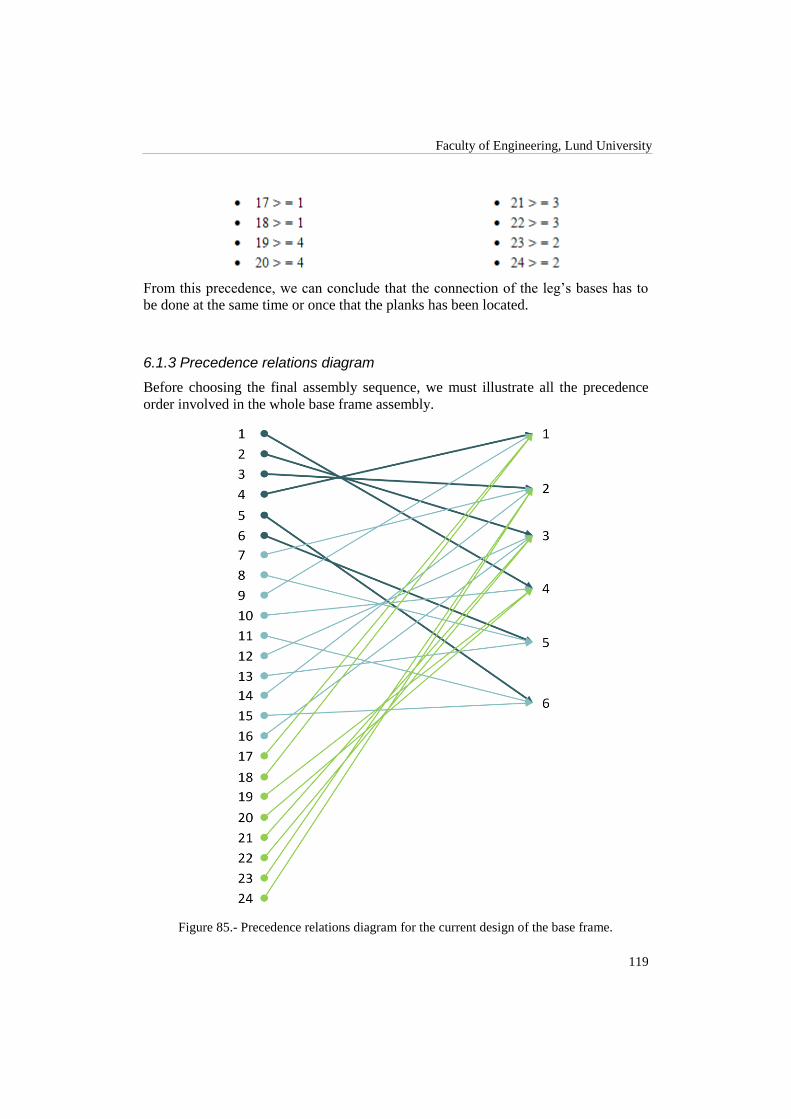
Faculty of Engineering, Lund University
119
From this precedence, we can conclude that the connection of the leg‟s bases has to
be done at the same time or once that the planks has been located.
6.1.3 Precedence relations diagram
Before choosing the final assembly sequence, we must illustrate all the precedence
order involved in the whole base frame assembly.
Figure 85.- Precedence relations diagram for the current design of the base frame.

Theoretical model
120
In figure 85, representing the conclusions of the Bourjault method, has been done a
diagram of the precedence relations for the Liaison diagram in figure 82. The lines
linking the different mates have been colored with the same shading of the Liaison
diagram for a more clear understanding of the relations. In other words, each color
represents a different subassembly.
6.1.4 Final sequence
In figure 86 is shown, from left to right, the theoretical assembly sequence for build-
ing the current base frame design. Each step is represented by the number of the liai-
son (mate) between the different pieces of the base frame. Notice that two or more
Liaisons in parentheses mean that they have to be done theoretically at the same time.
On the other hand, a dash between Liaisons means that the ones on the left have to be
done before the ones on the right.
Figure 86.- Final choice from the feasible sequences
The first pair of liaisons corresponds to the connections between L3 and L4 with the
right lateral plank (RL). Mates 17 and 24 are the ones between L1 and L2 with the
left lateral plank (LL). The third group corresponds to the mates between the rear
plank (RP) and both lateral planks (LL, RL). Also in this group the mates between the
leg‟s bases and RP are done. 5 and 6, and 2 and 3 indicates the connection of the main
joist (MJ) and the frontal plank (FP) with the lateral planks (LL, RL). The last group
contains also the Liaisons of the leg‟s bases with FP. The sixth and seventh steps are
the connections of the armrest‟s bases (AB1, AB2) with RP, FP and the lateral planks.
Finally, the two reminding groups correspond to the connections of the spring system
and the central beam with the main joist and the frontal plank.
We observe that the chosen sequence fulfills the precedence relation diagram. How-
ever, as the reader can deduce and as it is stated in the theory, a solution like (17,24) –
(20,21) – (2,3,22,23) – (5,6) – (1,4,18,19) – (10,11,12) – (7,8,9) – (15,16) – (13,14) is
also possible. Nevertheless, we have decided not to show the rest of feasible se-
quences as they do not add any value to the solution.

Faculty of Engineering, Lund University
121
6.2 Steps for Joining the Pieces
After describing the different parts making up the current sofa in chapter 4 and ac-
cording to the final sequence obtained following the assembly sequence analysis
stated in section 5.2, in this section are shown the necessary steps to assemble the
base frame.
To choose a real assembly sequence starting from the theoretical one, the main rec-
ommendations stated in the theoretical basis (chapter 3) have been followed. It‟s also
remarkable that the theoretical assembly sequence only considers the order of the
unions between pieces. However, in this section we are also defining the handling
order.
The principal justification for our design is that we have chosen a vertical from above
assembly direction. Other arguments are avoiding turning or rotating the structure,
placing the pieces preventing the need of holding them, the necessary gluing, stapling
or screwing operations, etc. We have also based our final selection on the experiences
from the visit made to the factory in Poland (section 4.4) and also on the knowledge
gathered about operations for automation.
6.2.1 Assembly process
As we are following the same assembly order, the sequence starts with the placement
of the leg‟s bases, namely L1, L2, L3 and L4. It is important to remark as this point
that it is necessary the use of a fixture that allows holding all the pieces together while
building the base frame.
Figure 87.- Placing leg´s bases

Theoretical model
122
The second step consists on placing the lateral planks (RL, LL) on the top of the leg‟s
bases. As stated before, here the mates 20, 21, 17 and 24 are done.
Figure 88.- Placing lateral planks
In the next step, the rear plank, the main joist and the frontal plank are placed in any
order.
Figure 89.- Placing planks
Following with the assembly, the armrest‟s bases are placed and fixed to the rest of
the structure.

Faculty of Engineering, Lund University
123
Figure 90.- Armrest‟s bases installation
Once the whole structure is built, the remaining pieces are installed to finish the as-
sembly process. The central beam is placed in position first and finally the spring
system is joined to both sides of the sofa structure (frontal plank and main joist).
Figure 91.- Placement of the central beam and springs

Theoretical model
124
6.3 Assembly Sequence Analysis: New Designs
In this section we will try to obtain the best possible assembly sequence for these new
designs. In order to avoid repeating the same processes for both designs, we will ex-
plain the whole procedure for the push-in system. Attending the similarities between
both designs, we have seen that the result for the click-in case is the same.
6.3.1 Liaison diagram
For generating the sequence, we will create the Liaison diagram taking profit of other
recent methods. As we have explained in section 3.1, “onion skin methods” reduce
the number of questions making the search of the feasible assembly sequences easier.
According to this method, we have split the base frame in three groups of parts. This
means that the analysis is divided in three steps. The assumption result of applying
onion skin methods says that all parts which have taken place at the first step form a
unique subassembly piece. Thanks to this, the same final result is preserved by the
time each step is simplified. Furthermore, we would not forget that our goal at this
part deals with giving real solutions based on theoretical researches.
An analyzed subassembly group will be represented either at the pictures or at the
diagrams with grey color.
6.3.1.1 First step: Principal structure
The push-in design, as have been described before, is conformed in this step by the
following parts with their corresponding abbreviations:
Rear plank: R
Main joist: M
Frontal plank: F
Left lateral plank: LL
Right lateral plank: RL

Faculty of Engineering, Lund University
125
Figure 92.- Design with abbreviations (1)
When all the parts are defined, we can build the “contact joints” between each part. In
the next figure we can see the different numbered links.
Figure 93.- Liaison diagram (1)
The numeration of each part connection will be crucial when ask and address prece-
dence questions take place. For this reason we have made a clear illustration of the
contact joists at the first stage.

Theoretical model
126
Figure 94.- Clear illustration of connections (1)
6.3.1.2 Second step: Armrest’s bases
For this second step, the parts involved in the previous steps are represented in grey.
In this case, these are only the ones in step one. The parts added in this step are the
armrest‟s bases. The following abbreviations are used for these new parts in figure
95:
Left armrest´s base: LA
Right armrest´s base: RA
Figure 95.- Design with abbreviations (2)
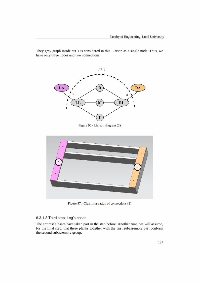
Faculty of Engineering, Lund University
127
They grey graph inside cut 1 is considered in this Liaison as a single node. Thus, we
have only three nodes and two connections.
Figure 96.- Liaison diagram (2)
Figure 97.- Clear illustration of connections (2)
6.3.1.3 Third step: Leg’s bases
The armrest´s bases have taken part in the step before. Another time, we will assume,
for the final step, that these planks together with the first subassembly part conform
the second subassembly group.

Theoretical model
128
The following abbreviations are used at the figure 98:
Leg´s base 1: L1
Leg´s base 2: L2
Leg´s base 3: L3
Leg´s base 4: L4
Figure 98.- Design with abbreviations (3)
Figure 99.- Liaison diagram (3)

Faculty of Engineering, Lund University
129
Figure 100.- Clear illustration of connections (3)
The next figure shows the final Liaison diagram for the whole frame. To represent
each subassembly group as well as each part, all the nodes with the same color belong
to a single subassembly.
Figure 101.- Final generation of the Liaison diagram

Theoretical model
130
6.3.2 Bourjault method
Once we have the corresponding Liaison diagram, we can proceed to generate all the
feasible assembly sequences. In this section is shown how we can reach some theoret-
ical sequences applying the Bourjault method.
The method is put into practice following the same steps than in the previous section.
Therefore, when we are analyzing a step, the subassemblies from previous steps are
considered again as a single node.
6.3.2.1 First step
Before start to formulate any question as the Bourjault method does, we will take
profit of the sofa´s geometry.
Figure 102.- Symmetric axes. Left y axis, right x axis
We can notice some symmetric axes where the sofa can rotate itself. For that reason,
we will study just two different contact joints instead of the six connection points as it
is shown in the figure below.
Figure 103.- Main contacts point to study

Faculty of Engineering, Lund University
131
22nndd QUESTION: R(2;1,3,4,5,6)
As we mention before, this contact joint is symmetric to the first one (rotation the
sofa in y axis). The conclusion that we have reached at the first question can be trans-
lated like:

Theoretical model
132
Now, because the symmetry
1 2 thus 2 >= 3,5
4 3 2 >= 1,3
33rrdd QUESTION: R(3;1,2,4,5,6)
Rotating the sofa in y axis and then x axis we will place the connection number three
at the same position as one was. Now, we can make the same procedure as in the first
question assuming:
1 3 3 >= 2,6
2 4 thus 3 >= 4,2
5 6
44tthh QUESTION: R(4;1,2,3,5,6)
The sofa can be rotated in x axis and place the connection 4 at the same place as con-
nection one was. Now, assuming another time the following translation:
1 4 4 >= 1,6
2 3 thus 4 >= 3,1
5 6

Faculty of Engineering, Lund University
133
66tthh QUESTION: R(6;1,2,3,4,5)
Finally the sixth connection point is symmetric respect of the fifth. In that case, once
analyzed the fifth one, we will translate it for this question:
1 4 6 >= 3,5
2 3 thus 6 >= 4,5
5 6
6.3.2.2 Second step
Any question for this part, like are described in section 6.3.2.1, should not be formu-
lated due to the triviality of this solution. Taking profit of the cutting technique, we
have split the design into several parts, so we will be able to formulate the further
conclusion since each subassembly is independent from the rest:
9>=2
10 >=3
11 >=4
12 >=1
6.3.2.3 Third step
The same as in section 6.3.2.2 is applied, thus:
7>=1,2,5
8>=3,4,6

Theoretical model
134
6.3.3 Precedence relations diagram
Before choosing the final assembly sequence, we must illustrate all the precedence
order involved in the whole base frame assembly. In figure 104, representing the con-
clusions of the Bourjault method, it is represented the diagram of precedence relations
for the Liaison diagram in figure 101. The lines linking the different mates have been
colored with the same shading of the Liaison diagram for a more clear understanding
of the relations. In other words, each color represents a different subassembly.
Figure 104.- Precedence relations diagram for the new designs of the base frame
6.3.4 Final sequence
In figure 105 is shown, from left to right, the theoretical assembly sequence for build-
ing both new designs. Each step is represented by the number of the liaison (mate)
between the different pieces of the base frame. Notice that two or more Liaisons in
parentheses mean that they have to be done theoretically at the same time. On the
other hand, a dash between Liaisons means that the ones on the left have to be done
before the ones on the right.
The first group of Liaisons (1, 4, 11 and 12) is the assembly of the rear plank with the
lateral planks and its corresponding leg‟s bases. Liaisons 5 and 6 consist in joining the
main joist to both lateral planks. The third group (2, 3, 9 and 10) is the union between

Faculty of Engineering, Lund University
135
the frontal plank, lateral planks and their leg‟s bases. Finally, Liaisons 7 and 8 are the
installation of left and right armrest‟s bases.
Figure 105.- Final choice from the feasible sequences
We observe that the chosen sequence fulfills the precedence relation diagram. How-
ever, as the reader can deduce, a sequence like (2,3,9,10) – (5,6) – (1,4,11,12) – 7 – 8
(frontal plank‟s mates, main joist‟s mates, rear plank‟s mates and armrest‟s bases) is
also possible. Nevertheless, we have decided not to show the rest of feasible se-
quences as they do not add any value to the solution.
(1,4,11,12) - (5,6) - (2,3,9,10) - 7 -8
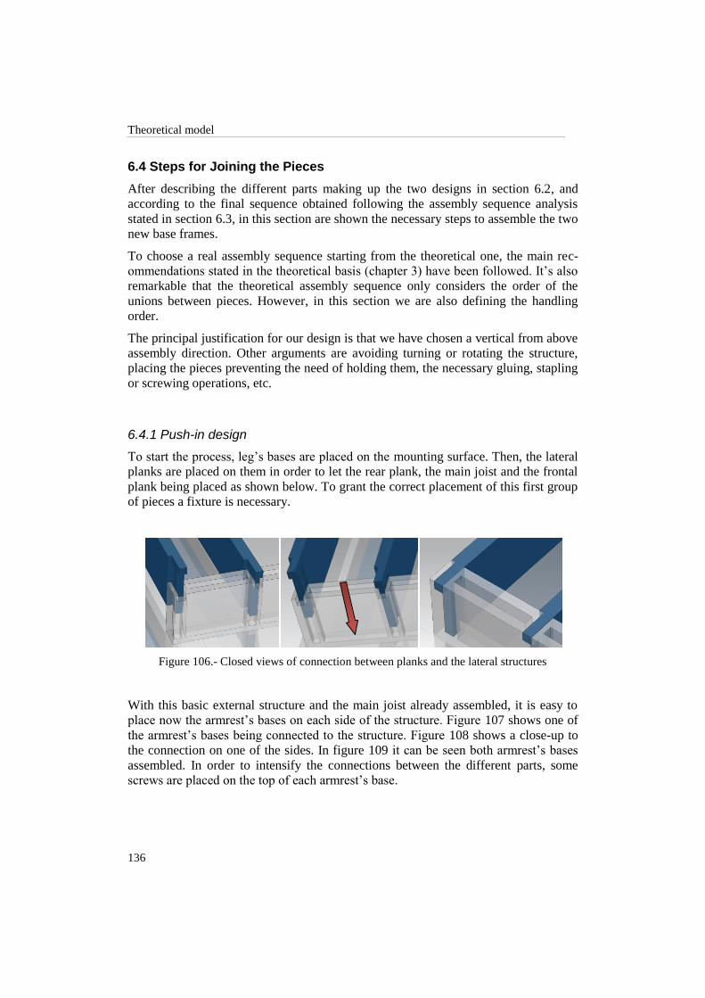
Theoretical model
136
6.4 Steps for Joining the Pieces
After describing the different parts making up the two designs in section 6.2, and
according to the final sequence obtained following the assembly sequence analysis
stated in section 6.3, in this section are shown the necessary steps to assemble the two
new base frames.
To choose a real assembly sequence starting from the theoretical one, the main rec-
ommendations stated in the theoretical basis (chapter 3) have been followed. It‟s also
remarkable that the theoretical assembly sequence only considers the order of the
unions between pieces. However, in this section we are also defining the handling
order.
The principal justification for our design is that we have chosen a vertical from above
assembly direction. Other arguments are avoiding turning or rotating the structure,
placing the pieces preventing the need of holding them, the necessary gluing, stapling
or screwing operations, etc.
6.4.1 Push-in design
To start the process, leg‟s bases are placed on the mounting surface. Then, the lateral
planks are placed on them in order to let the rear plank, the main joist and the frontal
plank being placed as shown below. To grant the correct placement of this first group
of pieces a fixture is necessary.
Figure 106.- Closed views of connection between planks and the lateral structures
With this basic external structure and the main joist already assembled, it is easy to
place now the armrest‟s bases on each side of the structure. Figure 107 shows one of
the armrest‟s bases being connected to the structure. Figure 108 shows a close-up to
the connection on one of the sides. In figure 109 it can be seen both armrest‟s bases
assembled. In order to intensify the connections between the different parts, some
screws are placed on the top of each armrest‟s base.

Faculty of Engineering, Lund University
137
Figure 107.- Placing one of the armrest base to the lateral profile
Figure 108.- Connection between armrest´s bases and lateral structures
Figure 109.-Placing the screws to fix the connections
The base frame is, at this point, almost assembled. Each leg‟s base is fixed to its cor-
responding corner as shown in figure 110 using screw too.

Theoretical model
138
Figure 110.- Attaching leg´s bases to the structure with screws
To finish with the assembly process, the central bracket and the springs are added.
Figure below shows the assembled base frame.
Figure 111.- Top view of the base frame completely assembled
6.4.2 Click-in design
As we are following the same assembly order, the sequence starts with the placement
of the leg‟s bases like in the push-in case. Likewise, the use of a fixture system is
necessary again in order to hold the pieces in the correct order.

Faculty of Engineering, Lund University
139
Figure 112.- Placing leg´s bases
The second step consists on placing the lateral planks. As opposite to the push-in, in
this case the union is already done, facilitating the whole process by removing the
final screwing operation to the leg‟s bases.
Figure 113.- Placing lateral planks
In the next step, the rear plank, the main joist and the frontal plank are placed in any
order.

Theoretical model
140
Figure 114.- Placing planks
Finishing with the assembly, the armrest‟s bases are placed and fixed to the rest of the
structure giving extra strength and resistance to the whole structure.
Figure 115.- Armrest‟s bases installation
Once the whole structure is built, the bracket and the springs are placed.

141
7 Design of the Assembly Lines
In this section we describe the assembly solutions that we have designed for fulfilling
all the requirements established previously in the theory and meeting the challenges
in terms of time and ease of assembly in order to improve the current assembly
process of the Ektorp sofa.
We would like to remark that this design has been performed in an iterative way. Our
starting point was theoretical design attending the problems detected during the anal-
ysis of the current sofa. Then, during the simulation, some other problems and chal-
lenges where found related to machinery, time requirements, costs and so on. For this
reason, the initial assembly lines have been refined along their design.
7.1 Overview of the Assembly Process: Current Design
As we mentioned previously in chapter 4, the Ektorp sofa is mainly formed by four
different kinds of parts: base frame, backrest, armrests and cushions. In order to de-
sign an assembly line that can be adapted to the current facilities of the assembly fac-
tory it is necessary to analyze, briefly, all the different modules involved in the con-
struction of the Sofa.
Figure 116 shows a diagram where is illustrated each part integrating the whole sofa
structure. The assembly approach is thought as different units or modules where each
part is built and, at the end of the module, is ready for packaging. Nevertheless, is
important to remark that the division between modules is just theoretical as in practice
all the modules can be interconnected, and workers and machinery from one module
can work and be reassigned to any of the work stations. Each square in the figure
represents a different module and immediately below are indicated the operations
made within them.
Figure 116.- Modules integrating the assembly of the sofa

Design of the Assembly Line
142
In this project, we are focusing on the assembly and upholstery of the base frame.
Figure 117 shows an inside of the corresponding module and the main processes in-
volved in its construction. We have split the processes of upholstery and the rest of
the assembly operation, in two different sub-modules: Upholstery and Assembly.
Later in this same chapter it will be explained the different alternatives available for
the design of this assembly line and it will be evidenced that the solution chosen
might not be necessarily divided into 2 physical separated modules.
Figure 117.- Base frame module
The upholstery module in figure 117 manages all the parts that are required to be
covered with a layer of foam and lining, namely frontal, rear and lateral planks, and
armrest‟s bases (see section 4.3.1). This process can be placed either at the beginning
or at the end of the assembly process. We have designed it with a modular approach
in order to be able to locate it where is considered to be more efficient and less time
consuming. If it is located at the end of the base frame assembly process, we would
have the same case structure as the one already implemented in Company A (see sec-
tion 4.4). However, we would like to focus the solution from a different perspective.
Therefore, we have decided to design this upholstery process for being placed at the
beginning of the assembly.
The assembly module in figure 117 contains all the processes that are necessary to put
together and to fix all the parts forming the base frame (see section 4.3.1). Due to the
processes involved in the production are ruled by precedence order, we have thought
this part of the assembly as a continuous production line, where conveyor systems,
workers and specialized machinery cooperate and maintain the assembly flow.

Faculty of Engineering, Lund University
143
7.2 New Assembly Process: Current Design
We have designed an assembly process for the current design of the base frame fol-
lowing the results that we obtained from all the analyses previously done and consi-
dering also the theory constraints and suggestions. In this way, the design presented
here below considers the following characteristics:
Precedence assembly order (see chapter 6).
Concurrence for optimizing working times.
Availability of seven robots already bought by Company A.
Reducing the number of quality tasks handled by human operators.
Saving resources such as glue, staples, lining and foam.
Dividing assembly times between similar stages to avoid processes getting
stuck waiting for other processes to start or to finish.
Modularity of the stages that would permit to adapt each part of the designed
assembly process according to the willing of the company.
In this way we have designed an assembly process that contains between seven and
eight stages. The first solution presented considers the upholstery of the pieces as a
separated process from the rest of the assembly, meanwhile in the second solution the
upholstery is directly linked to the rest of the stages. The rest of the process is com-
mon for both solutions.
7.2.1 Solution 1: Individual upholstery module
In figure 118 it can be observed the proposed deployment for an upholstery module
separated from the rest of the process. In this module, we work only with all the piec-
es with flat surfaces that require having a protecting layer of foam and lining, namely
frontal, rear and lateral planks as well as the armrest‟s bases.
These pieces then we considered to be stacked in an efficient way so that its transpor-
tation to the beginning of the line can be done with ease. In principle, we have chosen
a human worker for feeding the pieces into the system (figure 118 (a)). This can be
done in another way such as separated conveyors according to the pieces‟ kind, and
use a pick and place operation for placing each piece into the conveyor system. Nev-
ertheless, this solution would be expensive and unnecessary.
Next in the module, there is a conveyor that guides the pieces through the first stage
of the module: placing foam upon the pieces. This stage is formed by a gluing ma-
chine, a foam dispenser and a human worker (figure 118(b)). The gluing machine
supplies glue to each piece, while they cross under the machine, each time that a con-
troller button is pressed by the worker.

Design of the Assembly Line
144
Figure 118.- Upholstery module, solution 1
As the foam is placed all over the piece, there is no need of accuracy when supplying
the glue. The machinery then becomes simpler and consequently less expensive. After
the glue is spread over the part, the conveyor guides it to the worker. He is in charge
to take the foam from the dispenser and place it smoothly over the piece‟s surface. It
is necessary to remark that although this task is systematic, it will be the job of the
worker to place the correct foam size according to the type of part. After, he will have
to turn over the part and bring it to the next station.
The station for stapling the lining is formed by a specialized upholstery machine and
a human operator (figure 118(c)). The machine we had in mind for this design is a
fixture-aided system that would permit to fold the lining over the edges of the parts
and hold it while the stapling is done. The behavior would be similar to the mechan-
ism used by the machine seen on the video “CAMotion Robot Stretching and Stapling
Frame” [18]
. The worker in this station is responsible of placing the lining over the
fixture before the worker from the previous station brings a new part.
As the machine has to be adaptable according to size, we have though that the worker
in the station should operate the machine in order to keep standard quality in terms of
the upholstery and its finishing on each piece. In that way, the employee responsible
for the machine will have a control unit for operating the upholstery machine. After
the upholstery is done, the worker must take the part and place it in the conveyor for
being taken to the next stage.
The last stage in this module is the stacking of the already upholstered pieces (figure
118(d)). We have thought about a distribution system with conveyors that has the
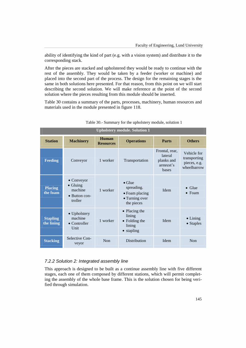
Faculty of Engineering, Lund University
145
ability of identifying the kind of part (e.g. with a vision system) and distribute it to the
corresponding stack.
After the pieces are stacked and upholstered they would be ready to continue with the
rest of the assembly. They would be taken by a feeder (worker or machine) and
placed into the second part of the process. The design for the remaining stages is the
same in both solutions here presented. For that reason, from this point on we will start
describing the second solution. We will make reference at the point of the second
solution where the pieces resulting from this module should be inserted.
Table 30 contains a summary of the parts, processes, machinery, human resources and
materials used in the module presented in figure 118.
Table 30.- Summary for the upholstery module, solution 1
Upholstery module. Solution 1
Station Machinery Human
Resources Operations Parts Others
Feeding Conveyor 1 worker Transportation
Frontal, rear,
lateral
planks and
armrest‟s
bases
Vehicle for
transporting
pieces, e.g.
wheelbarrow
Placing
the foam
Conveyor
Gluing
machine
Button con-
troller
1 worker
Glue
spreading.
Foam placing
Turning over
the pieces
Idem Glue
Foam
Stapling
the lining
Upholstery
machine
Controller
Unit
1 worker
Placing the
lining
Folding the
lining
stapling
Idem Lining
Staples
Stacking Selective Con-
veyor Non Distribution Idem Non
7.2.2 Solution 2: Integrated assembly line
This approach is designed to be built as a continue assembly line with five different
stages, each one of them composed by different stations, which will permit complet-
ing the assembly of the whole base frame. This is the solution chosen for being veri-
fied through simulation.

Design of the Assembly Line
146
7.2.2.1 First stage: Upholstery
This stage is very similar to the upholstery module described in section 7.2.1 with just
a few changes. Also the pieces involved in this stage are the same as in the first solu-
tion.
The feeding system of the pieces into the line is done also by a human worker (figure
119(a)). The main difference appears then in the transportation system. The conveyor
in this solution is divided, from the very beginning, in different rows in which the
different kinds of pieces (lateral, frontal or rear planks and armrest‟s bases) are
aligned. It could be possible to use as many separated conveyors as kind of pieces
exists. For our approach here, we will use one of the possible disposals as show in
figure 119: In line 1 we will line up the pieces corresponding to the lateral planks. In
line 2 we will feed the frontal and rear planks and the armrest‟s bases. The reason
behind this disposition will be clarified later in this same chapter.
Figure 119.- Upholstery stage, joined to the rest of the assembly line
In the station corresponding to the foam collocation (figure 119(b)), there will be also
a gluing machine as in the previous solution, but this time there will be one employee
working on each different row of the conveyor. They will have to complete the same
task of placing the foam over the pieces and then flipping and transporting them to the
next station. For our simulation approach, this stage will be represented by just one
employee for reasons of simplicity.

Faculty of Engineering, Lund University
147
The upholstery machine is the same as described before, but this time it will be neces-
sary either using two machines in parallel or doing just one piece at time, but estab-
lishing a control system for avoiding bottle-neck conflict in this station (figure
119(c)). The rest of the operations remain the same.
The pieces are then located in the conveyor system and taken to the next stage.
Figure 120 shows the corresponding stage being simulated in the Tecnomatix suite.
Figure 120(a) represents the feeding and the gluing station. Figure 120(b) shows the
station responsible for placing the foam. In figure 120(c) it can be observed the lining
stapling station.
Figure 120.- Upholstery stage
Table 31 contains a summary of the processes, machinery, pieces, human resources
and other items included in this first stage.

Design of the Assembly Line
148
Table 31.- Summary for the upholstery stage, solution 2
Upholstery stage. Solution 2
Station Machinery Human
Resources Operations Parts Others
Feeding Conveyor 1 worker Transportation
Frontal, rear,
lateral planks
and ar-
mrest‟s bases
Vehicle for
transporting
pieces, e.g.
wheelbarrow
Placing
the foam
2 Conveyors
Gluing
machine
Button
controller
2 workers
Glue
spreading.
Foam placing
Turning over
the pieces
Idem Glue
Foam
Stapling
the lining
Upholstery
machine
Controller
Unit
1 worker
Placing the
lining
Folding the
lining
stapling
Idem Lining
Staples
Stacking 2 conveyors Non Transportation Idem Non
Figure 121 shows two different stages: figure 121(a) show the placing and attaching
of the supports. Figure 121(b) and 121(c) represent the stage of picking and placing
the parts of the main structure of the base frame. We describe them in detail below.
Figure 121.- Attaching the supports and placing the basic structure

Faculty of Engineering, Lund University
149
7.2.2.2 Second stage: Placing and attaching the supports
This stage begins when the supports are placed again into the conveyor system (in
this case, into two different rows as explained before). It is necessary to remark that
each type of piece has to remain in the same row as they were before the upholstery
station (figure 121(a)). Along conveyor 1 it is transported the lateral planks, already
upholstered, and they pass under a gluing machine, although this time the gluing ma-
chine has to be able to spread glue in programmable points according to where the
supports are going to be placed, as they are fixed in different locations whether if it is
the right or the left lateral plank (see section 4.3.1.2).
For line number 2, transporting the frontal and rear planks and the armrest‟s bases,
the procedure followed is the same as in line 1. However, this time there are two em-
ployees working on the line. One is responsible of attaching the supports for armrest‟s
bases and the other one is in charge of placing the supports on the frontal and rear
planks. There is a controller system, one for each line, which permits the operators to
control the flow of the conveyors in order to get a new part into their workstation
once they have finished their corresponding operation. The pieces remain on the con-
veyor and are taken to the next stage.
It is at the beginning of this stage where the parts coming from the upholstery module
in solution 1 would be integrated to the assembly process. On figure 122 it is shown a
picture extracted from the simulation done for this stage.
Figure 122.- Placing and attaching the supports
In table 32 there have been summarized the machinery used, the human resources needed, the
operations done, the parts involved and other resources necessaries to complete this part of the
line.

Design of the Assembly Line
150
Table 32.- Summary for the attaching supports stage, solution 2
Attaching supports stage. Solution 2
Station Machinery Human
Resources Operations Parts Others
Placing
Supports
Conveyor
Gluing machine
3 workers
Glue spreading.
Supports placing
Stapling
Frontal, rear,
lateral planks
and armrest‟s
bases
Supports
Staples
7.2.2.3 Third stage: Pick & place
In figure 121(b) it is represented the first station of this stage with one robot, a con-
veyor system where the pieces to be picked arrive from the previous stage, one stack
that contains the leg‟s bases and a special fixture placed over a railed conveyor. The
fixture is such that aids the robot to locate each part in the proper position for being
joined subsequently in the line.
The robot is programmed to pick each leg‟s base from the stack and place it on the
corresponding position as shown in section 6.2. After locating the four leg‟s bases, it
takes, one by one, the lateral planks from the conveyor (line 1) and places them over
the fixture. When all these operations have been completed, the fixture, along with
the pieces already mounted on it, moves forward on the railed conveyor to meet the
second station of this stage. The conveyor is common for all the remaining stages.
The station placing the frontal and rear planks, the main joist7 and the armrest‟s bases
is illustrated in figure 121(c). There, the robot executes similar tasks than in the pre-
vious stage. First, it takes from the conveyor (line 2), the rear plank and places it in
the fixture. After, it takes the main joist from the stack where this part is piled up, and
it locates it in the position described in section 6.2. Once the main joist is placed, the
robot picks, one by one, the frontal plank, and both armrest‟s bases and finishes the
stage placing these parts inside the fixture. The conveyor, along with the fixture and
all the parts inside of it, moves forward to the next stage.
Figure 123 contains an image obtained from the simulation of this stage. Figure
123(a) shows the first work station and figure 123(b) illustrates the station were the
frontal and rear planks, main joist and armrest‟s bases are placed.
7 The main joist and the support attached to the frontal plank already contain the rapid clips necessary for
placing the spring system. The clips are assembled previously in a different department as described in
section 4.4.1.1.1.4

Faculty of Engineering, Lund University
151
Figure 123.- Picking and placing the parts of the base frame structure
In table 33 has been summarized the machinery used, number of worker, the opera-
tions and the parts involved in the stage along with other resources used for both sta-
tions of the third stage.
Table 33.- Summary for the pick & place stage, solution 2
Pick & place stage. Solution 2
Station Machinery Human
Resources Operations Parts Others
Placing leg’s
bases and
lateral planks
1 Robot
Conveyor
Railed conveyor
Non
Transporting
Pick and place
Leg‟s bases
and lateral
planks
Fixture
Placing frontal,
rear plank,
main joist and
armrest’s bases
1 Robot
Conveyor
Railed conveyor
Non Transporting
Pick and place
Frontal, rear
planks, main
joist and
armrest‟s bases
Fixture
Figure 124 exemplifies through a diagram the disposition of the two final stages of
the assembly line. Figure 124(a) represents the stapling stage of the planks, the main
joist and the armrest‟s bases. In figure 124(b) it is illustrated the stage for finishing
the assembly of the base frame by placing the central beam, the spring system and the
final lining cover over the springs.

Design of the Assembly Line
152
Figure 124.- Stapling and finishing stages
7.2.2.4 Fourth stage: Stapling
This stage, illustrated in figure 124(a), is composed by two stapling robots and the
fixture containing the parts that are going to be stapled. Robot 1 is in charge of stapl-
ing the rear plank with both lateral planks and the rear leg‟s bases. Subsequently it
staples also the left armrest‟s base and the left connection of the main joist. Robot 2
performs, at the same time, the same operation on the frontal plank, the frontal leg‟s
bases, the right armrest‟s base and the right connection of the main joist. Once fi-
nished the stapling, the fixture moves towards the next and last stage. In figure 125 is
shown a picture from the simulation of this stage.
Figure 125.- Stapling stage

Faculty of Engineering, Lund University
153
Table 34 summarizes the resources, operations and pieces that take part on this stage.
Table 34.- Summary for the stapling stage, solution 2
Stapling stage. Solution 2
Station Machinery Human
Resources Operations Parts Others
Stapling
1 Robot
Railed conveyor
Non Stapling
Leg‟s bases, frontal,
rear and lateral
planks, main joist and
armrest‟s bases
Fixture
7.2.2.5 Fifth stage: Finishing.
In this stage are added all the final parts in order to finish completely the base frame
assembly. In figure 124(b), it can be observed a diagram representing the correspond-
ing process involved in this stage.
First, the main structure already stapled and joined from the previous stage comes
along the conveyor in the fixture. Then, one worker is responsible for completing the
tasks of this working station. He must first take the central beam from a stack where
these pieces are piled up and place it over both, the main joist and the frontal plank.
Then, it is fastened by adding screws. Thereupon, the employee must take the springs,
also stacked up, and place them on both connections located on the main joist and the
frontal plank.
Finally, he is also responsible for adding the lining layer upon the springs and the
central beam. This layer needs to be stapled to the structure. The station and the stage
end when the worker press the button responsible for controlling the flow of the con-
veyor, allowing the finished base frame to be ready to be taken (figure 124(c)) and
joined with the backrest and subsequently transported to the packaging area. In figure
126 has been taken a snapshot from the simulation of this stage.
Figure 126.- Finishing stage

Design of the Assembly Line
154
In table 35 have been summarized the main resources, processes and pieces use in this
final stage.
Table 35.- Summary for the finishing stage, solution 2
Finishing stage. Solution 2
Station Machinery Human
Resources Operations Parts Others
Placing the
spring system,
central beam
and final cover
1 Robot
Railed conveyor
1 worker
Spring placing
Central beam placing
Stapling final layer of lining
Springs and
central beam
Lining
Foam

Faculty of Engineering, Lund University
155
7.3 Overview of the Assembly Process: New Designs
As mentioned in previous chapters, the scope of the project is limited to the base
frame of the Ektorp sofa. For this reason, the assembly line has only been designed to
build this part. Nevertheless, some parts of the line concerning other parts of the sofa
are also shown for clarity reasons.
It is also remarkable that we have tried to design the new assembly line trying to keep
a factory structure similar to the one observed during the visit to Company A. This
was motivated by our aim of keeping the design as real as possible in order to ensure
the possibility to move from the current line to our proposals. Moreover, the new line
is divided in individual stages, facilitating the progressive introduction to the current
line in a modular way.
In addition to this, the assembly line of the base frame is divided in three modules
corresponding to the three main phases of the current sofa production. The first one
corresponds to the assembly of its pieces. The second one concerns the addition of the
foam. Finally, in the third one the lining is placed.
The first and the second phases have been completely redesigned. On the other hand,
the lining module remains as currently because none of the proposals has beaten the
current one. For this reason, this last phase has not been redesigned or automated and
it is not described in this chapter.
Figure 127 shows the main operations performed in each one of the three stated mod-
ules.
Figure 127.- Base frame line modules

Design of the Assembly Line
156
The assembly process has been designed following the results obtained from all the
analyses previously done and considering also the theory and experiences. In this
way, the design presented considers the following characteristics:
Assembly sequence from section 6.3.
Concurrence for optimizing working times.
Saving resources such as glue, staples, lining and foam.
Dividing assembly times between stages to avoid processes getting stuck
waiting for other processes to start or to finish.
Modularity within the phases to gain adaptability and changeability in case of
modifications to the sofa structure or new designs.
The resulting assembly line is divided in eight stages. Three of them are in the assem-
bly part and the remaining five in the foam part.
The design of each module allows them to work independently from the others. How-
ever, in our design the assembly phase and the foam phase are directly connected.

Faculty of Engineering, Lund University
157
7.4 New Assembly Process: New Designs
In this section are described the assembly and the foam modules as well as its differ-
ent stages. Images showing the stages are presented along with tables summarizing
the required resources, operations and involved parts.
7.4.1 Assembly module
The assembly module is in charge of the building of the base frame and the installa-
tion of the central beam and the springs.
The assembly module, as can be seen in figure 128, is divided in three lines regarding
the parts making up the sofa. Starting from the top, the first line would be producing
armrests, the second one is assembling base frames and the third one would be build-
ing backrests.
Figure 128.- Assembly module
The inputs for each line are the different pieces that form every part of the sofa. The
outputs are in each line the corresponding assembled parts.
The base frame assembly line is split in three stages. The first one (figure 129(a))
corresponds to the robot on the left of figure 129. This robot places all the pieces in
the fixture. The second stage (figure 129(b)), performed by the second robot, screws
the entire structure. The final stage (figure 129(c)) is performed by the worker in the
right. He adds first the central beam and then places all the springs. A diagrammatic
representation of the line can be seen in figure 129.

Design of the Assembly Line
158
Figure 129.- Assembly module diagram
The following three subsections describe in deep each stage in the process while list-
ing the machinery, parts and operations involved.
7.4.1.1 First stage: Pick & place
This first stage locates the different pieces that make up the base frame in a fixture.
Figure 130.- Pick & place stage
The pieces are initially fed by a conveyor. Then, a robot picks the pieces from it and
builds the base frame following the assembly sequence presented in previous section
(leg‟s bases, lateral planks, rear plank, main joist, frontal plank and armrest‟s bases).
The fixture is attached to the railed conveyor that follows the entire assembly part of
the line.
Table 36 contains a summary of the processes, machinery, pieces, human resources
and other items included in this first stage.

Faculty of Engineering, Lund University
159
Table 36.- Summary for the pick & place stage
Pick & place stage
Machinery Human
Resources Operations Parts Others
Feeding Conveyor 1 worker Transportation
Frontal, rear and
lateral planks, main
joist, armrest‟s and
leg‟s bases
Vehicle for
transporting
pieces
Placing the
pieces
Railed
conveyor
1 Robot
Non Pick & place Idem Fixture
7.4.1.2 Second stage: Screwing the frame
In the second stage the push-in base frame is fastened with screws.
Figure 131.- Screwing the frame
The fixture with all the pieces already placed reaches the second workstation in the
line. It is composed by a robot equipped with a screwing tool and a screw feeder. The
base frame is quickly screwed from the top (armrest‟s bases to planks and main joist)
and the bottom (leg‟s bases to planks and main joist too). The fixture has gaps on the
bottom to allow screwing the leg‟s bases.
Table 37.- Summary for the screwing stage
Screwing stage
Machinery Human
Resources Operations Parts Others
Screwing
Railed
conveyor
1 Robot
Non Screwing Base frame
structure Screws

Design of the Assembly Line
160
7.4.1.3 Third stage: Central beam and spring system
In the last stage of the assembly module, the central beam and the springs are in-
stalled in the base frame structure. As stated in before, automating the spring installa-
tion presents enough challenges to justify keeping this process manual as it is current-
ly done. However, possible automatic solutions are also presented in that section.
Figure 132.- Placing central beam and spring system
The fixture with the fastened base frame arrives to the third workstation. There, a
worker installs first the central beam and then all the springs. The worker has a table
and a set of shelves with springs and central beams.
As this workstation is the only one that does not have a constant time, once the work-
er has installed all the pieces, he pushes a button to indicate the line controller that he
has finished the operation.
Table 38.- Summary for the third stage
Spring mattress stage
Machinery Human
Resources Operations Parts Others
Placing
central beam
and springs
Railed
conveyor 1 worker Pick & place
Screwing
Central beam
and springs 2 screws

Faculty of Engineering, Lund University
161
7.4.2 Foam module
In the foam module the necessary pieces of foam are glued to the base frame. Also at
the end of the module, in the last stage, the two pieces of lining and the piece of foam
covering the spring system is added.
As can be seen in figure 133, the foam module is also divided in three lines like the
previous one. As the lines in this module are connected to the previous one, the parts
in each line are the same. Starting from the top, the first line would be putting foam to
the armrests, the second one to base frames and the third one would be working in
backrests.
Figure 133.- Foam module
If we compare the new layout with the current Company A module (see section
4.4.1.1.1) we can notice that they are really similar. Again the idea is based on reus-
ing the available resources as much as possible, reducing the necessary time and in-
vestments to change the existing line. The only change is in gluing room 2. The cur-
rent room is only gluing one line while the new one allows gluing two lines like room
3 at the end of the module.
With this new layout, the armrests (in the top line) keep the same process and are
glued in room 1 and 3. The backrest (bottom line) maintains also the same process,
but is glued in room 2 through the new line. In the middle line, the base frame is
glued in rooms 2 and 3. This last process is similar to the existing one for the armrests
and has been designed because, currently in Company A, the foam is added to the
base frame in a different place.
Room 1
Room 2
Room 3

Design of the Assembly Line
162
Thus, the base frame gluing line is split in four stages plus one to transport from the
assembly module. The first one (figure 134(a)) corresponds to the orange and blue
structure in figure 133 used to move from the assembly module to the beginning of
the foam module. The second and the fourth stages (figure 134(b) and 134(d)), per-
formed in gluing room 2 and 3, do the gluing to the base frame. Third and fifth stages
(figure 134(c) and 134(e)) are performed by two couples of workers placing the foam
in the glued parts. Additionally, as commented before, in the fifth stage are added two
pieces of lining with one of foam in the middle, covering the spring mattress.
Figure 134.- Foam module diagram
The following subsections describe in deep each stage in the process while listing the
involved resources.
7.4.2.1 Fourth stage: Transport between modules
This stage transports the assembled base frame from the end of the assembly line to
the start of the foam line. The line is not continuous like the other ones because the
fixture used in the assembly line does not allow placing the foam on the planks. The
first fixture has external walls to avoid the external pieces of the base frame falling
before they are fastened together in the second stage. By contrast, in the foam line,

Faculty of Engineering, Lund University
163
with the structure already fastened, we need clear external sides in the fixtures in or-
der to glue first and place the foam then in the lateral, rear and frontal planks.
Figure 135.- Frame transport stage
For this reason, the structure located between lines picks up the base frame and moves
it to the foam line fixture designed to allow the foam attachment.
Table 39 contains a summary of this stage.
Table 39.- Summary for the transport stage
Base frame transport stage
Machinery Human
Resources Operations Parts Others
Transporting
Crane
Railed
conveyor
Non Transportation Base frame
structure Fixture
As a final comment about this stage, the displacement between lines has been consi-
dered a stage just to keep the structure of the chapter. In a real scenario or in future
analysis in this report this operation would be considered as the rest of movements
between stages, thus, included with the previous stage.
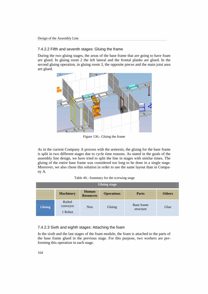
Design of the Assembly Line
164
7.4.2.2 Fifth and seventh stages: Gluing the frame
During the two gluing stages, the areas of the base frame that are going to have foam
are glued. In gluing room 2 the left lateral and the frontal planks are glued. In the
second gluing operation, in gluing room 3, the opposite pieces and the main joist area
are glued.
Figure 136.- Gluing the frame
As in the current Company A process with the armrests, the gluing for the base frame
is split in two different stages due to cycle time reasons. As stated in the goals of the
assembly line design, we have tried to split the line in stages with similar times. The
gluing of the entire base frame was considered too long to be done in a single stage.
Moreover, we also chose this solution in order to use the same layout than in Compa-
ny A.
Table 40.- Summary for the screwing stage
Gluing stage
Machinery Human
Resources Operations Parts Others
Gluing
Railed
conveyor
1 Robot
Non Gluing Base frame
structure Glue
7.4.2.3 Sixth and eighth stages: Attaching the foam
In the sixth and the last stages of the foam module, the foam is attached to the parts of
the base frame glued in the previous stage. For this purpose, two workers are per-
forming this operation in each stage.

Faculty of Engineering, Lund University
165
Figure 137.- Foam attach stage
The only difference between the two stages is that in the last stage are also added the
two pieces of lining with one of foam in the middle covering the spring mattress.
Similarly to the manual stage for the spring system in the assembly line, both foam
workstations have a security control system to indicate the line controller when the
operation is finished.
Table 41.- Summary for the third stage
Foam attach stage
Machinery Human
Resources Operations Parts Others
Placing
foam Non 2 workers
Attaching
foam
Base frame
structure Foam
Placing lining Non Idem Adding spring
cover Idem
Lining and
foam


167
8 Safety Framework
When dealing with robots and machinery in general in an automated environment
where those devices are constantly surrounded by people and also when that machi-
nery has to be operated by humans, it is necessary to establish and follow several
precautionary measures in order to maintain an adequate safety level on the work
environment, regarding both, workers and machinery safety guarantee.
Our assembly design is not the exception to this rule, therefore we have to develop
some specific working characteristics of the environment and the operation of the line
in such a way as the probability of a injured or harmed worker, or a malfunction of
the equipment is reduced as close to zero as possible.
Here below, we describe briefly the equipment, functions and preventions that must
be followed to guarantee a good and safe performance of the assembly design. We
have divided the framework into different areas depending on its kind, namely safety
regarding employees, machinery and robots.
8.1 Employees
While visiting the factory of Company A we noticed a serious lack of safety measures
among all the workers. For that reason, we list here a set of measures that we consider
it should be fulfilled by all the employees of the factory, in particular, for those work-
ing „inside‟ the assembly line:
It is mandatory the use of safety shoes during the whole working shift.
All those workers responsible for transporting pieces between the stations or
modules, and those working near to robot stations must wear safety helmets.
For those working on the assembly process and manipulating pieces should
be mandatory the use of safety glasses.
If the employee have to handle industrial equipment such as electric staplers,
electric cutters or any other industrial device it is mandatory the use of pro-
tective gloves.
If the employee has to handle materials that have been spread with chemical
substances, the use of a safety mask to avoid the inhalation of undesirable
gases and/or elements has to be mandatory.
The training on industrial safety should be mandatory to work in the factory.

Safety Framework
168
For those in charge of operating specialized machinery, the use of the ade-
quate equipment it is a must, as well as the completion of the training course
about the operation of the machine.
8.2 Machinery
Although the safety measures regarding the employees should guarantee their person-
al safety, the machinery involved in the industrial environment should have safety
characteristics for making them safer to use. Thus, machinery should fulfill the fol-
lowing requirements:
Safety switch, always easily reachable, for stopping the machinery in case of
an unexpected event. For further detail, the reader can consult the normative
EN/IEC 60204 of the European safety standards.
Ergonomic handles (if any) in order to avoid accidents due to mishandling,
slippery or uncomfortable positions.
Soft edges in those machines with possible sharp endings to reduce the risk of
injuries.
Specialized machinery should have clear indications of its use and the poten-
tially dangerous scenarios that could occur while its use.
Minimum amount of gaps to avoid crushing any part of the human body (fur-
ther details consult ISO/IEC 854).
Safety distances to prevent danger zones from being reached by upper or
lower limbs. (ISO/IEC 13852 and ISO/IEC 13853).
8.3 Robots
According to the ISO 13850:2006 and the EN775 for European standards, it is neces-
sary to fulfill a variety of normative when working with robots. The most important
safety measures are stated here below:
All the workstation that includes a robot should have safety fences in order to
control the proximity of humans to the robot and to avoid people crossing
over the work area.
The robot should have proximity sensors that activate the corresponding alert
signal within the system if for example there is an operator walking within
the workstation or an operator wants to move, check or adjust any issue re-
lated to the robot. While in the safety mode, the operations done by the robot
should decrease its velocity to minimal and if the proximity cross over a thre-
shold previously established, the robot must stop its operation and hold in

Faculty of Engineering, Lund University
169
safety mode until the operator have finished with the required adjustment or
when is safe for the robot and the operator to proceed its operation.
Once in safety mode, it is important regarding the safety of the processes and
the robot‟s program, that the latter is able to reinitialize from the same point
where it was before the system where halted.
There is a mandatory necessity on having an emergency button able to stop
safely the system in case of an unforeseen event. According to the ISO 13850
of 2006 the resetting of the emergency stop command is required to be ma-
nual. Therefore the emergency stop button must be always reachable for the
workers inside of the working station. See also the ISO/IEC 13850 normative.
The movements done by the robot must be controlled to avoid damages to ei-
ther the working pieces or the facilities. These controlled movements are ex-
pected also to be safe for the human working environment by guaranteeing
robot behavior. There have been cases where the employees of an automated
factory refused to work with industrial robots because they can hit or harm
them.


171
9 Simulation Results
In this chapter are presented the most important results that we have got from the
simulations and the designs done. We will focus our results on the assembly times
and the number of operations involved for each station.
9.1 Current Design
Table 42 shows each one of the different assembly times for the workstations illu-
strated in chapter 7. All these time values have been simulated with the Tecnomatix
software and they represent the time difference between the moments where a
workstation starts to operate until the subsequently station can be forwarded to begin.
In other words, it represents the time allowance to pass between one station and the
following one.
In order to summarize and compact our results, we have assigned a number to each
stage in the assembly process and a letter to each workstation contained on the cor-
responding stage. These alphanumeric codes are the same used in chapter 7. As a
reminder, here below we describe the used legend for our results:
Number 1 represents the upholstery stage. It is represented just from the
second station on as the first station (a) belongs to the feeding process and it
is not considered as a part of the assembly stations. Station 1(b) represents the
placing of the foam. Station 1(c) is referred to the upholstery process.
Number 2 represents the stage of placing and attaching the supports.
Number 3 represents the stage of picking and placing the parts of the main
structure. 3(a) makes reference to the station of placing leg‟s bases and lateral
planks. 3(b) represents the station of placing frontal, rear plank, main joist
and armrest‟s bases.
Number 4 stands for the stapling stage.
Number 5 was assigned to the finishing stage.
Table 42.- Workstations times
Workstation 1(b) 1(c) 2 3(a) 3(b) 4 5
Time(s) 39 46 79 82 51 38 89

Simulation Results
172
Table 43 shows the corresponding operations related to the assembly of each of the
parts involved in the assembly process of the current base frame. For each part are
listed the operations executed be workers, robots, conveyors and other kinds of ma-
chinery.
Table 43.- Parts and operations of the current base frame
Parts of the current base frame
Resource Lateral(2) Main Joist Frontal &
Rear planks
Armrest’s
bases (2)
Springs
Central
Beam
Leg’s
bases (4)
Worker
Foam
Transport(2)
Lining
Supports
Foam
Lining
Fittings
Foam
Transport(2)
Lining
Supports:
-(Frontal x2)
Fittings:
-(Frontal)
Transport(2)
Lining
Supports
Lining
Foam
Central B.
Springs(12)
-
Robot Pick&Place
Attaching Pick&Place Pick&Place
Pick&Place
Attaching -
Pick&Place
Attaching
Conveyor
Feeder
Transport
Fixtures(4)
Feeder
Fixtures(3)
Feeder
Transport
Fixtures(3)
Feeder
Transport
Fixtures(3)
Fixture(1) Feeder
Fixtures(4)
Machinery Gluing(2)
Lining -
Gluing(2)
Lining Gluing(2) - -
Operations 32 8 30 26 16 28
Total
Operations 140
As can be seen, a total number of one hundred and forty operations are carried out on
the different pieces making up the base frame.
To sum up, table 44 summarizes the required amount of resources in the simulation of
the new design of the assembly line. In total, seven workers are involved in the line,

Faculty of Engineering, Lund University
173
four robots perform different operations on it and three specialized machines collabo-
rate along the process.
Table 44.- Summary of resources in the current design line
Resource Amount
Workers 7
Robots 4
Specialized machinery 3
Two of the workers are placing the foam, one is in charge of the upholstery machine,
three work attaching supports to planks and the last one places the spring system to
the base frame. Two of the robots work in the pick & place for the base frame pieces
while the other two staple the structure in the stage after. Finally, there are two gluing
machines and an upholstery machine.
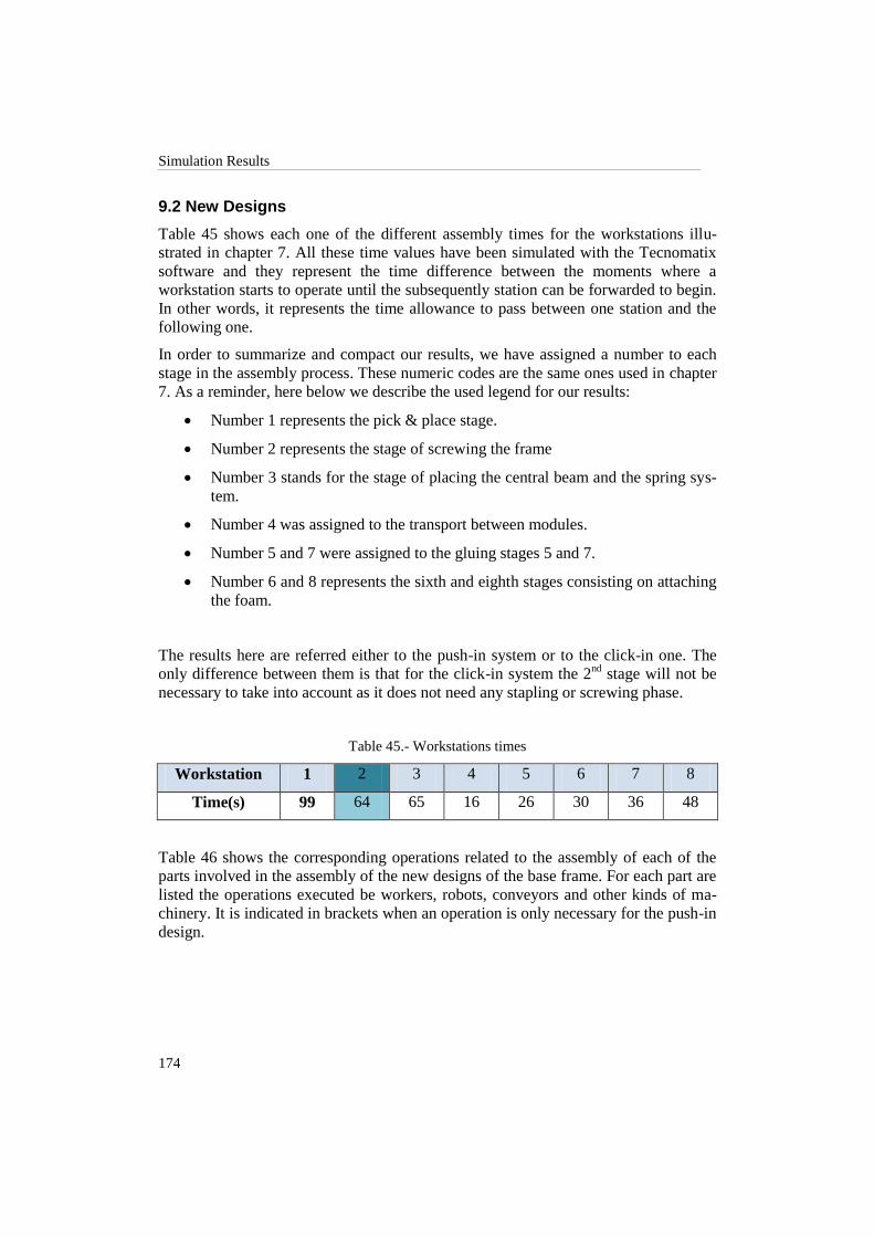
Simulation Results
174
9.2 New Designs
Table 45 shows each one of the different assembly times for the workstations illu-
strated in chapter 7. All these time values have been simulated with the Tecnomatix
software and they represent the time difference between the moments where a
workstation starts to operate until the subsequently station can be forwarded to begin.
In other words, it represents the time allowance to pass between one station and the
following one.
In order to summarize and compact our results, we have assigned a number to each
stage in the assembly process. These numeric codes are the same ones used in chapter
7. As a reminder, here below we describe the used legend for our results:
Number 1 represents the pick & place stage.
Number 2 represents the stage of screwing the frame
Number 3 stands for the stage of placing the central beam and the spring sys-
tem.
Number 4 was assigned to the transport between modules.
Number 5 and 7 were assigned to the gluing stages 5 and 7.
Number 6 and 8 represents the sixth and eighth stages consisting on attaching
the foam.
The results here are referred either to the push-in system or to the click-in one. The
only difference between them is that for the click-in system the 2nd
stage will not be
necessary to take into account as it does not need any stapling or screwing phase.
Table 45.- Workstations times
Workstation 1 2 3 4 5 6 7 8
Time(s) 99 64 65 16 26 30 36 48
Table 46 shows the corresponding operations related to the assembly of each of the
parts involved in the assembly of the new designs of the base frame. For each part are
listed the operations executed be workers, robots, conveyors and other kinds of ma-
chinery. It is indicated in brackets when an operation is only necessary for the push-in
design.
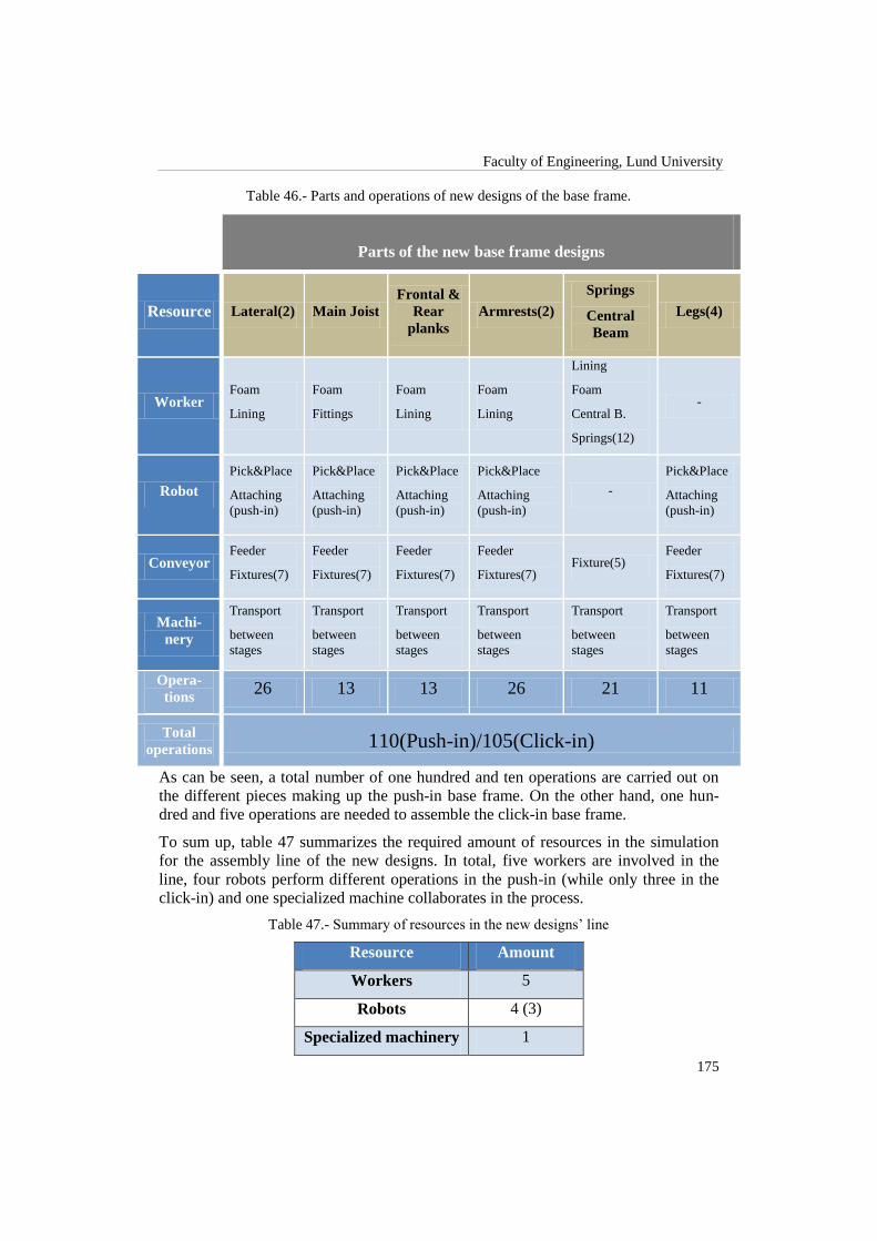
Faculty of Engineering, Lund University
175
Table 46.- Parts and operations of new designs of the base frame.
Parts of the new base frame designs
Resource Lateral(2) Main Joist
Frontal &
Rear
planks
Armrests(2)
Springs
Central
Beam
Legs(4)
Worker Foam
Lining
Foam
Fittings
Foam
Lining
Foam
Lining
Lining
Foam
Central B.
Springs(12)
-
Robot
Pick&Place
Attaching
(push-in)
Pick&Place
Attaching
(push-in)
Pick&Place
Attaching
(push-in)
Pick&Place
Attaching
(push-in)
-
Pick&Place
Attaching
(push-in)
Conveyor Feeder
Fixtures(7)
Feeder
Fixtures(7)
Feeder
Fixtures(7)
Feeder
Fixtures(7) Fixture(5)
Feeder
Fixtures(7)
Machi-
nery
Transport
between
stages
Transport
between
stages
Transport
between
stages
Transport
between
stages
Transport
between
stages
Transport
between
stages
Opera-
tions 26 13 13 26 21 11
Total
operations 110(Push-in)/105(Click-in)
As can be seen, a total number of one hundred and ten operations are carried out on
the different pieces making up the push-in base frame. On the other hand, one hun-
dred and five operations are needed to assemble the click-in base frame.
To sum up, table 47 summarizes the required amount of resources in the simulation
for the assembly line of the new designs. In total, five workers are involved in the
line, four robots perform different operations in the push-in (while only three in the
click-in) and one specialized machine collaborates in the process.
Table 47.- Summary of resources in the new designs‟ line
Resource Amount
Workers 5
Robots 4 (3)
Specialized machinery 1

Simulation Results
176
Four of the workers place the foam in the two stages while the other one places the
spring system. Two robots are in the foam module performing gluing operations, one
is in the pick & place in the beginning of the line and the last one screws the structure
(not necessary for the click-in design). Finally, the specialized machine is the struc-
ture transporting the base frame from the end of the assembly module to the begin-
ning of the foam line.

177
10 Analysis
In this section we analyze the results presented in chapter 9. We examine the possibil-
ities of improvements to the assembly design in order to improve the production rate
and to keep the tradeoff between the throughput per year and the feasibility of the
implementation of the design done.
10.1 Assembly Line for the Current Design
10.1.1 Workstation Times
As it has been shown in table 42 (chapter 9), the largest time operation in all the sta-
tions is the one corresponding to stage 5 in which are spent eighty nine seconds plac-
ing the springs, the central beam and the final cover.
It is observed that there is a huge difference between the times spent on each station.
With this situation, we would have idle workers or machinery waiting for the pre-
vious stage to be completed in order to be able to start their corresponding operation.
According to section 3.3.4.2 where an enhancement of the assembly line was men-
tioned, we have noticed in table 42 a huge difference in some of the workstation times
compared to the total average. We have to remember that in order to reduce produc-
tion times in an assembly line, it is necessary to reduce the time in each stage and if
this is not possible, try to reduce the total number of stages.
For that reason, we have decided to combine, first, the stations 1(b) with 1(c) and
second, 3(a) with station 4, since the time difference between each station should be
an acceptable minimum value, so that either the workers or the machinery involved in
each stage would be most of the time operating. Figure 138 shows the final work flow
motivated by the changes in workstation times and on table 48 has been illustrated the
new time deployment corresponding to the new „joined‟ stages.
Figure 138.- Combined arrangements of the current design

Analysis
178
Table 48.- Workstations times
Workstation 1(b),1(c) 2 3(a) 3(b),4 5
Time(s) 85 79 82 89 89
This modification does not imply an improvement regarding the production capacity
as the largest time in the line remains the same. Nevertheless, in this solution all the
stations involved in the assembly line will work, in approximation, the same average
time. It is remarkable to say that one could be tempted to increase as much as possible
the number of stations in order to obtain lower time values on each station and the-
reupon maximize the number of base frame per year. However, such solution rather
being feasible, it would be also expensive due to the large number of equipment and
employees required for such implementation. There has to be always a trade-off be-
tween number of stations, costs and production capacity.
10.1.2 Average Capacity
With the current base frame assembly times for each stage stated in the previous sec-
tion, we will have roughly a base frame produced every eighty nine seconds. Taking
into account the equation [x] from section 3.3.2, this value means a production capaci-
ty of 218.426 base frames per year (see appendix A, section A.1 for calculations).
In section 3.3.2 was also introduced the average capacity concept and its correspond-
ing equations. At this point, we have calculated the available operation time (equation
[x]).
First, we have to know the number of operations per unit. Assuming that a unit means
a base frame and each unit has several parts as it is shown in the table 44 (chapter 9)
and with the previous information, we have measured, in a proper way, the current
design assembly average capacity.
Using formulas described in section 3.3, the available time is approximately 0.72
seconds per operation (see Appendix A, subsection A.2)
10.1.3 Challenges and Issues within Assembly Design and Simulations
While developing the design of the assembly line, together with the simulations, we
were able to identify a variety of challenging situations and some issues related to
machinery physical limitations, parts holding and fastening, line-flow control, among
some others.
Regarding the machinery physical limitations, we observed that some processes that
we wanted to include in the line were not possible. For example, in the stapling stage,
we previously have thought having just one robot on charge of doing the whole stapl-
ing points along the base frame. Nevertheless, the reachable areas for the robot when

Faculty of Engineering, Lund University
179
it came to stapling operation were limited due to the mandatory 90 degrees orientation
of the robot joint jog that it had to maintain while the stapling process was done.
When placing the pieces to form the structure of the base frame, we found that it was
fundamental to simplify the operation for the robot by designing a specialized fixture
that allows placing in the proper positions each part, just by dropping, smoothly but
not necessarily accurately, the pieces into the mentioned fixture. Its shape and charac-
teristics are described on Appendix B.
Another important factor that was crucial when designing the assembly line was the
orientation of the parts. It was not desirable to have neither side rotations nor having
to flip over the structure as it would imply adding complex operations to the process
and consequently specialized machinery or larger times programming, resulting in an
increment of the costs.
The large amount of pieces contained in the current design of the base frame made
difficult the task of dividing the line in different stages and also it was challenging
locating and distributing the different pieces in a way that they could be reachable for
both, robots and employees.
10.1.4 Conclusion
As it has been mentioned in section 4.4, Company A generates 700.000 pieces per
year, nevertheless for Company A calculation, one piece means a base frame, a back-
rest or an armrest. Then, assuming that a sofa is built with 4 pieces and according to
the information we have, we will consider that Company A produces 175.000 base
frames per year (see appendix A for calculations).
Concluding, the production with our new assembly line design is, as stated before,
218.426 base frames per year. This means roughly an increment of 20% in the Com-
pany A´s current production capacity.

Analysis
180
10.2 Assembly Line for the New Designs
10.2.1 Workstation Times
As it has been shown in table 45 (chapter 9), the largest operation time in all the sta-
tions is the one corresponding to stage 1 in which are spent ninety nine seconds plac-
ing the whole structure of the base frame into the fixture.
This would generate a production capacity, taking into account the equation [x] from
section 3.3.2, of 196.363 base frames per year (see appendix B, section B.1 for calcu-
lations).
It is observed that there is a huge difference between the times spent on each station.
With this situation, we would have idle workers or machinery waiting for the pre-
vious stage to be completed in order to be able to start their corresponding operation.
According to section 3.3.4.2 where an enhancement of the assembly line was men-
tioned, we have noticed in table 45 a huge difference in some of the workstation times
compared to the total average. We have to remember that in order to reduce produc-
tion times in an assembly line, it is necessary to reduce the time in each stage and if
this is not possible, try to reduce the total number of stages.
For that reason, we decide to combine, first, the stations 4 with 5 and 7 and second,
station 6 with 8, since the time difference between each station should be an accepta-
ble minimum value, so that either the workers or the machinery involved in each
stage would be most of the time operating. Figure 139 shows the final work flow
motivated by the changes in workstation and on table 49 has been illustrated the new
time deployment corresponding to the new „joined‟ stages.
Figure 139.- Combined arrangements of the new designs
Table 49.- Workstations times
Workstation 1(a) 1(b) 2 3 4,5,7 6,8
Time(s) 55 55 64 65 78 78
With this modification in the assembly system for the new designs of the base frame,
there is an improvement on the production capacity as it would produce one base
frame each 78 seconds.
Taking into account the equation [x] from section 3.3.2, this last value means a capaci-
ty production of 249.230 base frames per year (see appendix B, section B.2). In this

Faculty of Engineering, Lund University
181
solution all the stations involved in the assembly line will work, approximately, in the
same average time. It is remarkable to say that one could be tempted to increase as
much as possible the number of stations in order to obtain lower time values on each
stage and thereupon maximize the number of base frame per year. However, such
solution rather being feasible, it would be also expensive due to the large number of
equipment and employees required for such implementation. There has to be always a
trade-off between number of stations, costs and production capacity.
10.2.2 Average Capacity
In section 3.3.2 was introduced the average capacity concept and its corresponding
equations. At this point, we have calculated the available operation time (equation
[w]).
First, we have to know the number of operations per unit. Assuming, at this point, that
a unit means a base frame and each unit has several parts and with the previous in-
formation, we have measured in a proper way the new designs assembly average ca-
pacity.
Using formulas described in section 3.3, the available time is roughly 1.02 seconds
per operation (see Appendix B, subsection B.2) before joining the stages. After the
improvement is done, the available time operation is approximately 0.8 seconds.
10.2.3 Challenges and Issues within Assembly Design and Simulations
While developing the design of the assembly line, together with the simulations, we
were able of identify a variety of challenging situations and some issues related to
machinery physical limitations, parts holding and fastening, line-flow control, among
some others.
Regarding the machinery physical limitations, we observed that some processes that
we wanted to include in the line were not possible.
When placing the pieces to form the structure of the base frame, we found that it was
fundamental to simplify the operation for the robot by designing a specialized fixture
that allows placing in the proper positions each part, just by dropping, smoothly but
not necessarily accurately, the pieces into the mentioned fixture. It was necessary also
to add some holes located in specific points in order to fasten the parts with screws in
the case of the push-in design. The final shape of the fixture and its characteristics are
described on Appendix B.
Once solved the problem about placing properly the parts, we challenged another
issue related to the placement of the foam and the lining over the assembled structure.
The previous fixture used in the placing stage had high wall borders in order to keep
the pieces together and make easier their placement. However, for the stages corres-
ponding to the foam and lining placing, these borders on the sides were an obstacle to
appropriately place the foam and the lining over the planks and the armrest‟s bases.

Analysis
182
For that reason it was designed a second fixture that had the function of holding the
already assembled base frame structure but this time without those edges. A transpor-
tation stage had to be designed also in order to change the base frame between differ-
ent fixtures.
Another important factor that was crucial for designing the assembly line was the
orientation of the parts. It was not desirable to have neither side rotations nor having
to flip over the structure as it would imply adding complex operations to the process
and consequently specialized machinery or larger times programming, resulting in an
increment of the costs.
For meeting the challenge about compatibility between both designs (click-in and
push-in), it was necessary to change, on an earlier phase of the project, the design of
the click-in system. Before the redesign of this solution, the click-in parts were joined
by sides movements as the plugs were located on the sides on a ninety degrees angle
referred to the part. The final design was created for a vertical from above assembly
approach.
10.2.4 Conclusions
As it has been mentioned in section 4.4, Company A generates 700.000 pieces per
year, nevertheless for Company A calculation, one piece means a base frame, a back-
rest or an armrest. Then, assuming that a sofa is built with 4 pieces and according to
the information we have, we will consider that Company A produces 175.000 base
frames per year (appendix B for calculations).
Concluding, the production with our new assembly line design is, as stated before,
196.363 base frames per year using the stage distribution resulting from the simula-
tion and 249.230 base frames per year after the improvement performed after the
analysis (section 10.2). This means roughly an initial increment of 12‟5% over Com-
pany A´s current production capacity and 30% after the improvement.

183
11 Further Work
Although we have verified the applicability of the designed assembly line by validat-
ing the theoretical model through simulations, it is imperative to do a study work
about materials and the possible limitations related to the different designs. Once that
have been decided the type of materials that should be used to construct the base
frame, it would be advisable to test the chosen designs through computer based simu-
lations in terms of the stiffness, strength and durability according to IKEA‟s test re-
quirements.
The conclusions here obtained can be used as a study basis for extending the study
case to the remaining parts of the Ektorp sofa, namely backrest and armrest. It is re-
markable that the design done for the assembly line was thought for integrating some
of its modules to the processes corresponding to the backrest and armrest assembly
lines. For example, there are some robots in the solution presented that have idle
times that can be used on another line. If they are strategically located and can reach
the necessary pieces, they can perform processes of the same kind (e.g. screwing,
gluing, upholstery, etc.).
Further improvements should be also focused on studying the possibilities about us-
ing other materials on the upholstery process in order to reduce the use of glue and
staples. As stated formerly there exist on the market some textiles with thermal sensi-
tive properties that can be easily attached to the structure by heating them. Still and
all, one should keep in mind the principle constriction of any further investigations
regarding new technologies and it is the sustainability and the environmental friendly
characteristics as a must.
We recommend as well doing future studies related to the control system of the as-
sembly line and going into further details about the working characteristics of the
upholstery machine as well as the robot programming strategy that would be used in
case of implementation of any of the assembly designs.
Finally, we suggest doing a business study of the solutions here presented. In that way
it would be possible to have a comparison point in terms of profitability between the
different cases. Nevertheless, the study about materials should be done first with the
aim of having all the information needed for a business case.


185
12 Conclusions
There are several topics that we have concluded after the long descriptions, simula-
tions and analysis of either the design of the current Ektorp Sofa or its production
way. We have done a deep study for the whole base frame structure based on a theo-
retical assembly bases within the point of view of the current manufacturing and as-
sembly world.
It is extremely important for a company or factory that the designs of the products and
its assembly systems should be developed together. They must be in touch and gener-
ate changes to each other. This concept of parallelism will improve the production
time and capacity. In addition, it will enhance the product quality reaching a huge
level of competitive in the current market.
Also, we have shown that using another kind of materials, enhancements in the prod-
uct quality and the assembly system designs will be reached.
Finally, through the simulation software, it was possible to show all the suggestions
and real results that were based on theoretical models. With this, we have met some
challenges in a satisfactory way, increasing the current capacity and improving the
spent times in the sofa production.
As can be seen on table 50 we have reduced the production time in the current base
frame design. Each worker in the current base frame assembly process in Company A
is delivering a base frame every three hundred seconds. With the new assembly line
presented, we would deliver one every eighty eight seconds. Furthermore, the esti-
mated production that we would reach is nearly two hundred and twenty thousand
base frames per year. Thus, Company A would gain on a 20% production increase.
Table 50.- Current design final conclusions
Delivery time Throughput
Before study 300sec / base frames. 175.000 base frames/ year
After study 88sec / base frames 218.426 base frames/ year
About the number of pieces making up the base frame, we can see in table 51 that
except for the case of plastic frames the number has been increased. However, in the

Conclusions
186
case of the push-in solution, hundreds of staples and the glue have been changed by
twenty four screws. Furthermore, something similar happens in the case of the click-
in, where forty plugs have been added also removing gluing and stapling. It is also
remarkable that in the plastic design the clips are consolidated with the main joist and
the frontal plank and for this reason the values have that noticeable decrease.
Table 51.- Comparison between current and new designs (number of pieces)
Within the prices of base frames made of different materials, as it was expected, the
price of the wood frame is the most competitive. On the other side we find the Nylon
6 frame with a price roughly ten times higher than wood structures. Nevertheless, this
material makes possible the consolidation of the clips and decreases the difficulty of
the production of the pieces by reducing the production time using molding tech-
niques. These reasons support the selection of polypropylene because, although its
resistance and stiffness is lower than the Nylon 6, the same advantages are present
and the price is clearly lower. A steel frame is also competitive in terms of price and
its stiffness is definitely the best one. However, it increases the weight and new ways
to attach clips and upholstery have to be researched.
Table 52.- Comparison between current and new designs (prices)
Number of pieces
Wood Steel PA6 +
30% GF PP
Current Design 80 - - -
Push-in system - 87
63
63
Click-in system 103
103 79 79
Total price (€)
Wood Steel PA6+30%
GF PP
Current Design 17,13 - - -
Push-in system - 34,79 114,15 34,46
Click-in system 29,30 33,65 147,60 56,27

Faculty of Engineering, Lund University
187
About production, as shown in table 53 the capacity of the new assembly line together
with the new designs is certainly increased compared with the current design. A base
frame is delivered every seventy eight seconds, resulting in nearly two hundred and
fifty thousand base frames per year. In other words, a 30% production increment.
Table 53.- Comparison between current and new designs (capacity)
Delivery time Throughput
Current design 300sec / base frames. 175.000 base frames/ year
Push-in / Click-
in 78sec / base frames 249.230 base frames/ year
Finally, as shown in table 54, the necessary workers and resources required in the
current base frame assembly and the new designs is really different. While the current
assembly line has more than thirty workers assembling the different parts of the sofa,
attaching foam and adding the lining, for the new designs, only five workers are
needed as the rest of the operations have been automated. Consequently, the robots
and specialized machinery has been increased in these new designs. The foam line
remains with two robots like the current one, but one robot is added for pick & place
operations in both designs and one more for screwing in the push-in. However, the
addition of two robots is justified by the increment in the throughput in the new lines
as can be seen in table 53.
Table 54.- Comparison between current and new designs (resources)
Current design Push-in Click-in
Workers > 30 5 5
Robots 2 4 3
Specialized
machinery 0 1 1


References
[1] Boothroyd, G., 2005, Assembly Automation and Product Design, (2nd
Edition). CRC Press:
Boca Raton, FL, USA.
[2] Boothroyd, G., Dewhurst, P., Knight, W., 2001, Product Design for Manufacture and
Assembly, (2nd
Edition). Marcel Dekker: New York, USA.
[3] Whitney, D. E., 2004, Mechanical Assemblies - Their Design, Manufacture, and Role in
Product Development, Oxford Series on Advanced Manufacturing, Oxford University Press.
[4] Redford, A. H. & Chal, J., 1994, Design for Assembly: Principles and Practice, McGraw-
Hill Europe: Maidenhead, Berks, UK.
[5] Otto, K. & Wood, K., 2001, Product Design: Techniques in Reverse Engineering and New
Product Development, Prentice Hall: Upper Saddle River, NJ, USA
[6] Miyakawa, S., Ohashi, T. and Iwata, M., 1990, The New Hitachi Assembleability Evalua-
tion Method (AEM), Proceedings of NAMRI, SME.
[7] Niimi, A. and Matsudaira, Y., 1997, Development of a New Vehicle Assembly Line at
Toyota: Worker-Oriented, Autonomous, New Assembly System, Springer: Berlin, Germany,
pp. 82-92.
[8] Whitney, D. E., 2004, Mechanical Assemblies: Their Design, Manufacture, and
Role in Product Development, Oxford University Press: Oxford, USA, pp. 391-392.
[9] Graves, S. C. & Holmes-Redfield, C., 1988, Equipment Selection and Task Assignment for
Multiproduct Assembly System Design, International Journal of Flexible Manufacturing Sys-
tems, vol. 1, pp. 31-50.
[10] Encyclopedia Britannica, 2010, Furniture Industry, Encyclopedia Britannica Online,
http://www.britannica.com/EBchecked/topic/222678/furniture-industry [Accessed April 28,
2010 at 11:13].
[11] IKEA, 2010, Our responsibility – IWAY, our code of conduct,
http://www.ikea.com/ms/en_GB/about_ikea/our_responsibility/iway/index.html [Accessed
April 28, 2010 at 13:20].
[12] IKEA, 2010, About IKEA - The IKEA way,
http://www.ikea.com/ms/en_GB/about_ikea/the_ikea_way/index.html [Accessed April 28,
2010 at 13:28].
[13] Company A, 2005, Company, http://fabryka.com40.pl/en/firma.php/ [Accessed April
28, 2010 at 13:41].

References
190
[14] Li, X. & Zhang, S., 2009, “Automatic Assembly Planning for Virtual Assembly”, Pro-
ceedings of the 2009 IEEE International Conference on Mechatronics and Automation,
Changchun, China.
[15] Tradekey, 2010, Automatic cushion weighing and filling line,
http://www.tradekey.com/product_view/id/779932.htm [Accessed April 27, 2010].
[16] Siemens, 2005, UGS Corporation completes the acquisition of Tecnomatix,
http://www.plm.automation.siemens.com/en_us/about_us/newsroom/press/press_release.cfm?
Component=25556&ComponentTemplate=822 [Accessed May 28, 2010]
[17] ABB Robotics, 2007, “Changes for Chinese tobacco”, Packaging magazine, June 2007,
pp. 3.
[18] CAMotion Robot Stretching and Stapling Frame, 2009, Camotion robotics (online vid-
eo), http://www.youtube.com/watch?v=y_7rZoyxtaY [Accessed May 25, 2010].

Appendix A: Throughput Calculations
A.1 Company A Capacity
A.2 Current Design Capacity
Using equation [w] from section 3.3.2
Using equation [u] from section 3.3.2
Using equation [v],[w] and [x] from section 3.3.2


Appendix B: Throughput Calculations
B.1 Company A Capacity
B.2 New Designs Capacity
B.2.1 With the largest operation of 99 seconds.
Using equation [w] from section 3.3.2
Using equation [v] from section 3.3.2
Using equation [w], [v] and [x] from section 3.3.2

194
B.2.2 With the largest operation of 78 seconds.
Using equation [w] from section 3.3.2
Using equation [v] from section 3.3.2
Using equation [v],[w] and [x] from section 3.3.2

Appendix C
195
Appendix C: Fixture Design
In figure 140 is shown one of the fixtures designed in order to make easier for robot
resources operations like pick and place or screwing.
At time of building the base frame, it is important to have a fix place where the dif-
ferent pieces keep the corresponding connection between them. We can observe some
protuberances inside the fixture motivated by that idea of placing in an established
position the whole structure. In addition, it is notable that most of the parts of this
design have a common chamfer with an acceptable inclination. That facilitates the
pieces getting inside in each place with the correct orientation and position.
In order to allow fastening the legs from the bottom, the fixture has some grooves at
each corner. This is necessary either for the current or the push-in design. In this way,
flipping over the entire structure can be avoided. However, the automation of these
fastening operations on the bottom of the structure requires complicate robotic
movements to reach the corners.
Figure 140.- Fixture for the current design´s assembly line.
The other fixture design, represented at figure 141, was motivated in order to imple-
ment operations of gluing and placing the foam over the different planks. For that
reason, the lateral sides were taken off. The same design as before was left in order to
avoid any movements in the fixture that would carry problems in following opera-
tions.

196
Figure 141.- Fixture for the current design´s assembly line.
Related Documents