AVAILABLE ONLINE AT: INITIATED BY: www.directives.doe.gov Office of Management DOE G 413.3-4A 9-15-2011 Technology Readiness Assessment Guide [This Guide describes suggested non-mandatory approaches for meeting requirements. Guides are not requirements documents and are not to be construed as requirements in any audit or appraisal for compliance with the parent Policy, Order, Notice, or Manual.] U.S. Department of Energy Washington, D.C. 20585 NOT MEASUREMENT SENSITIVE

Welcome message from author
This document is posted to help you gain knowledge. Please leave a comment to let me know what you think about it! Share it to your friends and learn new things together.
Transcript
AVAILABLE ONLINE AT: INITIATED BY:
www.directives.doe.gov Office of Management
DOE G 413.3-4A
9-15-2011
Technology Readiness Assessment Guide
[This Guide describes suggested non-mandatory approaches for meeting requirements. Guides
are not requirements documents and are not to be construed as requirements in any audit or
appraisal for compliance with the parent Policy, Order, Notice, or Manual.]
U.S. Department of Energy Washington, D.C. 20585
NOT
MEASUREMENT
SENSITIVE


DOE G 413.3-4A i (and ii)
9-15-11
FOREWORD
This Department of Energy (DOE) Guide is for use by all DOE elements. This Guide assists
individuals and teams involved in conducting Technology Readiness Assessments (TRAs) and
developing Technology Maturation Plans (TMPs) for the DOE capital asset projects subject to
DOE O 413.3B, Program and Project Management for the Acquisition of Capital Assets, dated
11-29-10. This Guide presents a tailored version of a National Aeronautics and Space
Administration (NASA) and Department of Defense (DoD) technology readiness assessment
model to assist in identifying those elements and processes of technology development required
to ensure that a project satisfies its intended purpose in a safe and cost-effective manner that will
reduce life cycle costs and produce results that are defensible to expert reviewers. DOE Guides
are part of the DOE Directives Program and are issued to provide supplemental information and
additional guidance regarding the Department’s expectations of its requirements as contained in
rules, Orders, Notices, and regulatory standards. Guides may also provide acceptable methods
for implementing these requirements but are not prescriptive by nature. Guides are not
substitutes for requirements, nor do they replace technical standards that are used to describe
established practices and procedures for implementing requirements.


DOE G 413.3-4A iii (and iv)
9-15-11
TABLE OF CONTENTS
1.0 Introduction .................................................................................................................... 1
1.1 Purpose ............................................................................................................................ 1
1.2 Background ..................................................................................................................... 1
1.3 Technology Development Process Model ..................................................................... 3
2.0 Technology Readiness Assessment Process Model ...................................................... 7
2.1 Relationship of TRAs and TMPs to the DOE Critical Decision Process ................ 12
2.2 Relationship of TRAs to Independent Project Reviews ............................................ 15
3.0 Model for Identifying Critical Technology Elements (CTEs) ................................... 16
4.0 Model for Technology Readiness Level Assessments................................................. 20
4.1 Supporting Documentation for the Technology Readiness Levels Assessments .... 25
4.2 CTEs Assessments for Maturity (Technology Readiness Level) ............................. 28
4.3 Technology Readiness Level Calculator .................................................................... 28
4.4 TRA Report .................................................................................................................. 29
5.0 Technology Maturation Plan ....................................................................................... 30
5.1 Process Overview.......................................................................................................... 30
5.2 TMP Preparation ......................................................................................................... 31
5.3 TMP Execution ............................................................................................................. 32
Appendix A: Glossary............................................................................................................... A-1
Appendix B: Acronyms ............................................................................................................ B-1
Appendix C: References ........................................................................................................... C-1
Appendix D: Template for a Technology Readiness Assessment (TRA) Review Plan ...... D-1
Appendix E: Template for the Identification of Critical Technology Elements (CTEs) .... E-1
Appendix F: Template Examples for the TRL Assessment Calculator as Modified for
DOE-EM ..................................................................................................................................... F-1
Appendix G: Template for a TRA Report .............................................................................. G-1
Appendix H: Template Guide for a Technology Maturation Plan ...................................... H-1

DOE G 413.3-4A 1
9-15-11
1.0 Introduction
1.1 Purpose
Technology development is the process of developing and demonstrating new or unproven
technology, the application of existing technology to new or different uses, or the combination of
existing and proven technology to achieve a specific goal. Technology development associated
with a specific acquisition project must be identified early in the project life cycle and its
maturity level should have evolved to a confidence level that allows the project to establish a
credible technical scope, schedule and cost baseline.1 Projects that perform concurrent
technology development and design implementation run the risk of proceeding with an
ill-defined project baseline. The purpose of this document is to present a tailored version of a
proven NASA and DoD technology assessment model that will assist DOE Program Offices in
identifying those elements and processes of technology development required to reach proven
maturity levels to ensure project success. A successful project is a project that satisfies its
intended purpose in a safe, timely, and cost-effective manner that would reduce life-cycle costs
and produce results that are defensible to expert reviewers (Reference: DoD Technology
Readiness Assessment Deskbook, July 2009).
This document was developed to assist individuals and teams that will be involved in conducting
Technology Readiness Assessments (TRAs) and developing Technology Maturation Plans
(TMPs) for the Department of Energy (DOE) capital acquisition assets subject to DOE
O 413.3B, Program and Project Management for the Acquisition of Capital Assets. TRAs and
TMPs activities are a tool to assist in identifying technology risks and enable the correct
quantification of scope, cost and schedule impacts in the project. This document is intended to
be a “living document” and will be modified periodically as the understanding of TRA processes
evolves within the DOE programs. DOE programs could use this Guide (the TRA process
model) to assist in the development of their own TRA Process Guides/Manuals tailored to
their own particular technologies and processes. A program TRA Guide/Manual should take
precedence over the DOE G 413.3-4A when conducting a TRA for projects under that specific
program, as applicable to their technologies and/or processes.
DOE G 413.3-4A should not be applicable or appropriate to a project if: (1) the technology was
adequately demonstrated previously for identical situations in one or more separate projects (see
Appendix H, section 2.0, Technology Heritage); or (2) the technology readiness level does not
apply if the objective of the project is to research scientific principles.
1.2 Background
To meet the requirements of DOE O 413.3B, Independent Project Reviews (IPRs) are one of the
measures that can be implemented to ensure the timely resolution of engineering, system
integration, technology readiness assessments, design, quality assurance, operations,
1 DOE O 413.3B, Table 2.1, requirement for hazard Category 1, 2 and 3 nuclear facilities to conduct an Integrated Project Review
(IPR) to ensure early integration of safety in the design of a facility. For example, if a safety system requires technology development, then it must be identified early in the project life cycle. (Refer to DOE G 413.3-9 and DOE-STD-1189-2008)

2 DOE G 413.3-4A
9-15-11
maintenance of nuclear safety issues (Reference: DOE G 413.3-9, U.S. Department of Energy
Project Review Guide for Capital Asset Projects). The purpose of an IPR is to acknowledge,
identify, and reduce technical risk and uncertainty. The IPR also increases visibility of the risks
and identifies any follow on activities that need to take place to mitigate the risks. Technical risk
reduction increases the probability of successful achievement of technical scope. IPRs can
include TRAs, as applicable and appropriate, to provide an assessment of the maturity level of a
new proposed technology prior to insertion into the project design and execution phases to
reduce technical risk and uncertainty. A TRA provides a snapshot in time of the maturity of
technologies and their readiness for insertion into the project design and execution schedule. A
TMP is a planning document that details the steps necessary for developing technologies that are
less mature than desired to the point where they are ready for project insertion. TRAs and TMPs
are effective management tools for reducing technical risk and minimizing potential for
technology driven cost increases and schedule delays.
A TRA evaluates technology maturity using the Technology Readiness Level (TRL) scale that
was pioneered by the NASA in the 1980s. The TRL scale ranges from 1 (basic principles
observed) through 9 (total system used successfully in project operations). See section 2.0 for an
explanation of the adaptation of the TRLs model in the context of DOE projects.
In 1999, the General Accounting Office (GAO) (GAO/NSIAD-99-162) recommended that the
DoD adopt NASA’s TRLs as a means of assessing technology maturity prior to transition. In
2001, the Deputy Undersecretary of Defense for Science and Technology issued a memorandum
that endorsed the use of TRLs in new major programs. Subsequently, the DoD developed
detailed guidance for performing TRAs using TRLs in the 2003 DoD Technology Readiness
Assessment Deskbook [updated in July 2009]. Recent legislation (2006) has specified that the
DoD must certify to Congress that the technology has been demonstrated in a relevant
environment (TRL 6) prior to transition of weapons system technologies to design or justify any
waivers. TRL 6 is also used as the level required for technology insertion into design by NASA;
it is normally the last stage where technology has been demonstrated in the engineering/pilot
scale in the relevant environment.
In March of 2007, the GAO issued a report on the results of a review of DOE projects
performance which concluded, among other findings, that DOE’s premature application of
technologies was a reason for cost growth and schedule extension. GAO recommended that
DOE adopt the NASA/DoD methodology for evaluating new technology maturity in their major
construction projects (Reference: GAO-07-336). Subsequently, the DOE Office of
Environmental Management (EM) conducted several pilot TRAs in their projects using an
adaptation of the NASA/DoD TRA model for evaluating technology maturity and reported that
the benefits of using the TRAs process include providing a structured, criteria-based, and clearly
documented assessment. The process also identifies specific actions to reduce risk, assists in
comparing candidate technologies, promotes decision-making discipline, and improves technical
communication.
In an April 2008 report on the root cause analysis of contract and project management
deficiencies within DOE, it was concluded that DOE has not always ensured that critical new
technologies in final project designs have been demonstrated to work as intended. This has led
to scope, cost and schedule increases from the originally approved project baselines (Reference:
DOE G 413.3-4A 3
9-15-11
DOE Root Cause Analysis, Contract and Project Management, April 2008). A Corrective
Action Plan to this report was approved in July 2008 which addressed this shortcoming by
planning the development of a DOE-wide technology readiness level model to assist DOE
programs in the performance of TRAs for new technologies in their major construction and
cleanup projects. The Corrective Action Plan includes a metric that requires, by the end of FY
2011, all projects greater than $750M (i.e., Major System Projects) applying new technology to
implement technology readiness assessment methodologies no later than Critical Decision-2
(CD-2), as applicable and appropriate. [Reference: Root Cause Analysis, Contract and Project
Management, Corrective Action Plan, July 2008]. Section 1.3 in this Guide provides further
guidance with a strong message that TRA assessments by the programs for critical new
technologies should begin early in the critical decision process. Technology development and
associated risks are a key component of the project alternatives down select process and a key
item in baseline cost and schedule development which begins at CD-1.
1.3 Technology Development Process Model
Various technical baseline deliverables, including associated technology development, are
produced as a project evolves from pre-acquisition design to operation. The technology
development process is not limited to the pre-acquisition and conceptual development stages, but
instead, transitions throughout the life of the project. In addition, a safety strategy input is
required early in the project life cycle as part of the technology development process.2 The
process recognizes the evolution of the project and the iteration necessary to continue support of
the design. This integrated technology development approach also addresses emerging issues
related to the technology that are driven by the design process, to include the corresponding
safety function.
Figure 1 identifies the integration of the technology development phases with the project stages.
In practice, technology development precedes design, which is followed by design
implementation (construction). This is depicted with bold blue arrows signifying completion of
technology development activities supporting the follow-in process in the project development.
Also the red arrows at the bottom part of the figure reflect the early continuous interaction of the
plant support group (operations) with the technology development and design group for setting
process and performance requirements to support plant startup, commissioning and operations.
The following sub-sections provide suggested guidance to line management within projects or
programs to ensure that technology development activities are brought to an appropriate level of
maturity and transitioned for each project stage with a continued effort to reduce technological
risk, as applicable and appropriate to the specific project and DOE program.
2 DOE O 413.3B, Table 2.1, a safety design strategy is required for Hazard Category 1, 2 and 3 nuclear facilities for projects
subject to DOE-STD-1189-2008.

4 DOE G 413.3-4A
9-15-11
Figure 1. Technology Development Integration with Project Management.
1.3.1 Technology Development Program Plans
Technology development plans are prepared when new technology development activities are
identified during project planning. They provide a comprehensive planning document describing
technology development activities required for the successful execution of the project, and the
development relationship to the overall project scope and schedule relative to project phases.
Areas addressed by the plan should include process needs identification, selection, system
engineering, evaluation, performance verification, and demonstrations.
In support of technology development, it usually follows that a roadmap is developed to provide
the technology development path forward for successful deployment of the selected technology.
A work scope matrix is then developed that expands on the roadmap. The matrix provides the
high-level details of each segment of research and development, assigning responsibility for the
execution of each segment and documenting the path through each segment in the form of logic
diagrams that are linked to the roadmap.
1.3.1.1 Process Needs Identification, Selection, and Evaluation
Process needs identification, selection, and evaluations occur during the pre-acquisition and
conceptual design stages. Within these stages, as applicable and appropriate, the technology
development program identifies the needs and requirements of a system or component and
associated risks. This may include laboratory or pilot work to better understand system or
process performance. The product of these activities provides input to performance requirement
DOE G 413.3-4A 5
9-15-11
documents and criteria. Involving the plant support group early at this stage will help to ensure
the manufacturability of designs, plants can presents lessons learned from previous designs, and
suggest design improvements, as well as help identify the critical new technologies.
The next step in this effort involves selecting equipment that meets or most closely meets the
performance requirements or criteria. In the selection process, existing equipment or processes
are utilized to the maximum extent possible. However, in many cases, particularly those
processes performed in hazardous or remote environments, the equipment may not be
commercially available. In these situations, efforts are made to adapt commercial technologies
to the specific environment and requirements. During this activity, the available equipment is
compared and those identified as most closely meeting the defined requirements are selected for
further evaluation.
Equipment and or process evaluation involves experimental or pilot facility testing of the
process or equipment identified in the selection process. Although selection identified those
processes and equipment that most closely meet design requirements, it is not uncommon for
evaluation of those selected processes and equipment to identify areas where the process or
equipment fails to meet requirements. In those cases, it may be necessary to return to the
selection of alternatives to modify or select another preferred option. The following
subsections describe various activities used to support the identification, selection, and
evaluation of the selected technology.
Assessments and Studies
Inherent with technology development is the risk associated with first-of-kind applications. A
technical risk assessment should be performed to identify risks that may affect the achievement
of technical objectives that ultimately affect cost, schedule and performance. Results of
technical risk assessments and risk-handling strategies are factored into technical
assessments/reviews and studies [References: DOE G 413.3-7A; DOE G 413.3-9; and DOE O
413.3B].
Technical assessments and studies are conducted during the pre-acquisition project stage to
evaluate and select the design approach that best meets the customer’s goals, objectives, and
preliminary technical and functional requirements. Topics addressed during this activity should
include, as applicable, supporting program risks, technology maturation risks, process
technology, facility concepts, major system concepts, component technology, safety, and
risk-handling strategies identified through completion of technical risk assessments.
Review of Alternatives
Results of technology development assessments and studies are documented and reviewed to
determine the validity of the approach that best meets project goals, objectives, and the
physical, functional, performance, and operational requirements of the project at the best
value; to include testing and validation of all required functions, including any safety
functions.

6 DOE G 413.3-4A
9-15-11
A team consisting of members from the customer, engineering, operations, maintenance
organizations, technology development program management, and selected subject matter
experts reviews the documented assessments and study results. The team review focuses on
the results of the assessments and studies relative to the alternatives considered, evaluation of
systems used to select the recommended design approach, and the potential life-cycle cost
savings. The objective of the review is to review the documented assessment and study
evidence to identify the basis for endorsing the selected design approach, including
development and testing of the technology to ensure its maturation in subsequent project
phases.
Small-Scale and Proof-of-Concept Testing
Small-scale and proof-of-concept testing is performed at the conceptual project stage to verify
initial assumptions relative to system and process performance. Test results are compared with
the initial input parameters. Based on the reviews of test results, refinements in the technology
(i.e., its design) are applied when necessary to ensure that the technology concept meets project
requirements prior to the start of project design activities. As necessary, the technology
development program plans are modified consistent with these test results.
1.3.2 Performance Verification
Performance verification occurs during the design and construction project stages. Once a
process or equipment has been selected and proven to perform in an acceptable manner,
verification against the design requirements is performed to ensure that the process or equipment
will perform properly in the operating environment. Verification addresses performance of the
selected process or equipment on both the component level and from an integrated system
perspective. Verification attributes may include checking that the operating parameters are
within the operating envelope of supporting systems (e.g., power, feed rate, etc.) as well as
meeting the physical expectations of the equipment or examining properties of material produced
against the stated requirements.
Following verification activities, full-scale testing to assess the durability and reliability of the
process and/or equipment is conducted. Integrated runs involving combining components,
systems, or processes are performed to provide a demonstration of process conditions over
extended periods of time and provide opportunities of process optimization. This testing stage is
intended to prove that the long-term operating goals, especially where remote operations are
required, can be reliably achieved while producing the end product at acceptable quality
standards in a safe and controlled manner.
1.3.3 Plant Support
Following construction completion, support for the new technology is provided through start up
and turnover to operations. This continued integration of technology development provides an
opportunity for the operations technical staff to attain a better understanding of the technology
application. However, it is recommended that the plant support group involvement should start
early in the pre-acquisition and conceptual phases to ensure the manufacturability of designs, to

DOE G 413.3-4A 7
9-15-11
incorporate lessons learned from previous designs and operational experiences, and to help in the
identification of what the new critical technologies are in the project (see Figure 1).
1.3.4 Technology Readiness Assessment (TRA) Reviews
IPR teams may be established to conduct TRA reviews and provide recommendations to the
program/project sponsor and the Acquisition Executive in terms of the project technology
readiness and maturity. These review teams serve in an advisory capacity at key project design
points such as CD-0, CD-1, CD-2, and CD-3. (see section 2.0). At a minimum, team
membership may consist of senior-level technical personnel and subject matter experts on the
project. The team should also be able to leverage outside experts as appropriate to contribute to
the review process. The team should perform its review relying on documented reports and other
formal evidence, and minimize reliance on verbal assurances from project personnel. A
technology review report is issued after each review, presenting the results of the review and
specific recommendations for maturing technologies relative to the design process, as needed.
When this IPR review activity includes a sub-team of experts that are selected from personnel
who are independent of the project, the sub-team reviews can be considered to satisfy the
expectation to conduct a TRA, as discussed in the sections of this Guide that follow.
Ad hoc teams of subject matter experts may also perform additional technology development
reviews at any point in the development process. These reviews target specific areas of
development. The results from these reviews and recommendations are formally communicated
to the project team and user.
1.3.4.1 Records
Records retention is usually dictated by customer/program requirements and the requirements
from DOE O 413.3B in support of the project reviews process, and to support the formulation of
lessons learned reports. Because of the significant documentation generated by technology
development activities, judgment should be exercised prior to discarding any documented plans,
reports, or studies utilized to validate technology development selection and test results.
2.0 Technology Readiness Assessment Process Model
“A TRA is a systematic, metric-based process and accompanying report that assesses the
maturity of certain technologies [called Critical Technology Elements (CTEs)] used in systems.”
[2003 DoD Technology Readiness Assessment Deskbook (updated July 2009)].
The TRA is an assessment of how far technology development has proceeded based upon
documented evidence. It is not a pass/fail exercise and is not intended to provide a value
judgment of the technology developers or the technology development program. It is a review
process to ensure that critical technologies reflected in a project design have been demonstrated
to work as intended (technology readiness) before committing to construction expenses. TRAs
should be conducted by technically qualified personnel who are independent of the project. A
TRA can:

8 DOE G 413.3-4A
9-15-11
Identify the gaps in testing, demonstration and knowledge of a technology’s current
readiness level and the information and steps needed to reach the readiness level required
for successful inclusion in the project;
Identify at-risk technologies that need increased management attention or additional
resources for technology development; and
Increase the transparency of management decisions by identifying key technologies that
have been demonstrated to work or by highlighting immature or unproven technologies
that might result in increased project risk.
The TRA process model consists of three sequential steps:
(1) Identifying the Critical Technology Elements (CTEs). CTEs are the at-risk
technologies that are essential to the successful operation of the facility, and are new
or are being applied in new or novel ways or environment (see section 3.0 for more
details of CTEs).
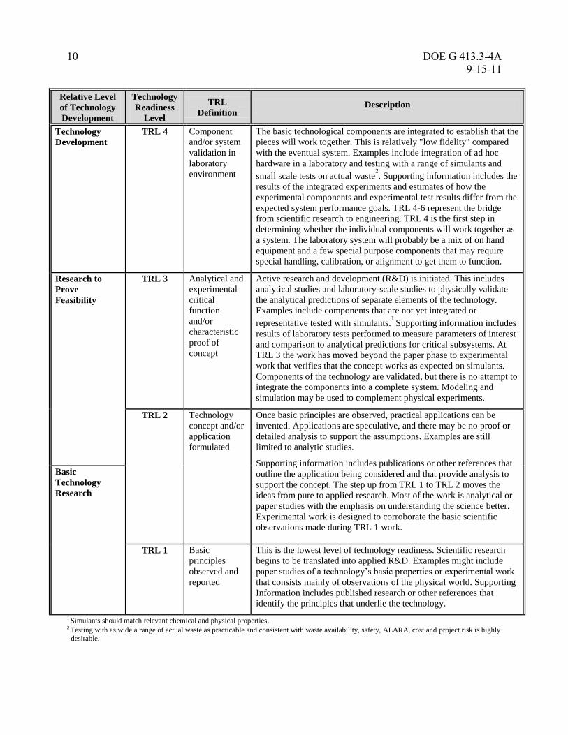
(2) Assessing the Technology Readiness Level (TRL). The TRL scale used by the
DoD and NASA, and adopted by EM in their pilot demonstration program is used for
conducting Technology Readiness Assessments. Other DOE programs, in developing
their own program guides/manuals, should consider lessons learned from EM, DoD
and NASA, and their own domain or experience in measuring technology readiness,
as applicable and appropriate to their specific projects and programs. TRL indicates
the maturity level of a given technology, as defined in Table 1 primarily for hardware
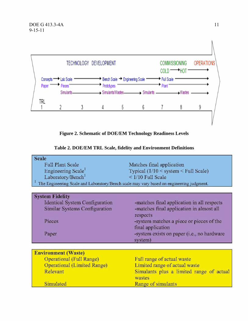
items. Figure 2 provides a schematic of the meaning of the TRL’s in the context of
DOE/EM waste processing projects. The TRL scale ranges from 1 (basic principle
observed) through 9 (total system used successfully in project operations). TRL is
not an indication of the quality of technology implementation in the design. Testing
should be done in the proper environment and the technology tested should be of an
appropriate scale and fidelity. A DOE/ EM example of the TRL requirements and
definitions regarding testing “scale,” “system fidelity,” and “environment” are
provided in Tables 2 and 3. (See section 4.0 for more details on TRLs)
(3) Developing a Technology Maturation Plan (TMP). If the TRL level for a CTE
does not meet the expectation level at each Critical Decision level (especially for CD-
2 and later), then a maturity level gap exists that requires further evaluation testing or
engineering work in order to bring the immature technology to the appropriate
maturity level. The development or revision of a Technology Maturation Plan (TMP)
identifies the activities required to bring immature CTEs up to the desired TRL (see
section 5.0 for more details on the TMP).

DOE G 413.3-4A 9
9-15-11
Table 1. Technology Readiness Levels
Relative Level
of Technology
Development
Technology
Readiness
Level
TRL
Definition Description
System
Operations
TRL 9 Actual system
operated over
the full range
of expected
mission
conditions.
The technology is in its final form and operated under the full range of
operating mission conditions. Examples include using the actual
system with the full range of wastes in hot operations.
System
Commissioning
TRL 8 Actual system
completed and
qualified
through test
and
demonstration.
The technology has been proven to work in its final form and under
expected conditions. In almost all cases, this TRL represents the end
of true system development. Examples include developmental testing
and evaluation of the system with actual waste in hot commissioning.
Supporting information includes operational procedures that are
virtually complete. An Operational Readiness Review (ORR) has been
successfully completed prior to the start of hot testing.
TRL 7 Full-scale,
similar
(prototypical)
system
demonstrated
in relevant
environment
This represents a major step up from TRL 6, requiring demonstration
of an actual system prototype in a relevant environment. Examples
include testing full-scale prototype in the field with a range of
simulants in cold commissioning1. Supporting information includes
results from the full-scale testing and analysis of the differences
between the test environment, and analysis of what the experimental
results mean for the eventual operating system/environment. Final
design is virtually complete.
Technology
Demonstration
TRL 6 Engineering/pi
lot-scale,
similar
(prototypical)
system
validation in
relevant
environment
Engineering-scale models or prototypes are tested in a relevant
environment. This represents a major step up in a technology’s
demonstrated readiness. Examples include testing an engineering
scale prototypical system with a range of simulants.1 Supporting
information includes results from the engineering scale testing and
analysis of the differences between the engineering scale, prototypical
system/environment, and analysis of what the experimental results
mean for the eventual operating system/environment. TRL 6 begins
true engineering development of the technology as an operational
system. The major difference between TRL 5 and 6 is the step up
from laboratory scale to engineering scale and the determination of
scaling factors that will enable design of the operating system. The
prototype should be capable of performing all the functions that will
be required of the operational system. The operating environment for
the testing should closely represent the actual operating environment.
Technology
Development
TRL 5 Laboratory
scale, similar
system
validation in
relevant
environment
The basic technological components are integrated so that the system
configuration is similar to (matches) the final application in almost all
respects. Examples include testing a high-fidelity, laboratory scale
system in a simulated environment with a range of simulants1 and
actual waste2. Supporting information includes results from the
laboratory scale testing, analysis of the differences between the
laboratory and eventual operating system/environment, and analysis
of what the experimental results mean for the eventual operating
system/environment. The major difference between TRL 4 and 5 is
the increase in the fidelity of the system and environment to the actual
application. The system tested is almost prototypical.
10 DOE G 413.3-4A
9-15-11
Relative Level
of Technology
Development
Technology
Readiness
Level
TRL
Definition Description
Technology
Development
TRL 4 Component
and/or system
validation in
laboratory
environment
The basic technological components are integrated to establish that the
pieces will work together. This is relatively "low fidelity" compared
with the eventual system. Examples include integration of ad hoc
hardware in a laboratory and testing with a range of simulants and
small scale tests on actual waste2. Supporting information includes the
results of the integrated experiments and estimates of how the
experimental components and experimental test results differ from the
expected system performance goals. TRL 4-6 represent the bridge
from scientific research to engineering. TRL 4 is the first step in
determining whether the individual components will work together as
a system. The laboratory system will probably be a mix of on hand
equipment and a few special purpose components that may require
special handling, calibration, or alignment to get them to function.
Research to
Prove
Feasibility
TRL 3 Analytical and
experimental
critical
function
and/or
characteristic
proof of
concept
Active research and development (R&D) is initiated. This includes
analytical studies and laboratory-scale studies to physically validate
the analytical predictions of separate elements of the technology.
Examples include components that are not yet integrated or
representative tested with simulants.1 Supporting information includes
results of laboratory tests performed to measure parameters of interest
and comparison to analytical predictions for critical subsystems. At
TRL 3 the work has moved beyond the paper phase to experimental
work that verifies that the concept works as expected on simulants.
Components of the technology are validated, but there is no attempt to
integrate the components into a complete system. Modeling and
simulation may be used to complement physical experiments.
TRL 2 Technology
concept and/or
application
formulated
Once basic principles are observed, practical applications can be
invented. Applications are speculative, and there may be no proof or
detailed analysis to support the assumptions. Examples are still
limited to analytic studies.
Supporting information includes publications or other references that
outline the application being considered and that provide analysis to
support the concept. The step up from TRL 1 to TRL 2 moves the
ideas from pure to applied research. Most of the work is analytical or
paper studies with the emphasis on understanding the science better.
Experimental work is designed to corroborate the basic scientific
observations made during TRL 1 work.
Basic
Technology
Research
TRL 1 Basic
principles
observed and
reported
This is the lowest level of technology readiness. Scientific research
begins to be translated into applied R&D. Examples might include
paper studies of a technology’s basic properties or experimental work
that consists mainly of observations of the physical world. Supporting
Information includes published research or other references that
identify the principles that underlie the technology.
1 Simulants should match relevant chemical and physical properties. 2 Testing with as wide a range of actual waste as practicable and consistent with waste availability, safety, ALARA, cost and project risk is highly
desirable.
DOE G 413.3-4A 11
9-15-11
DO
E G
413.3
-4
11
DR
AF
T X
X-X
X-0
9
Figure 2. Schematic of DOE/EM Technology Readiness Levels
Table 2. DOE/EM TRL Scale, fidelity and Environment Definitions

12 DOE G 413.3-4A
9-15-11
Table 3. DOE/EM TRL Testing Requirements
* Note: See Tables 5 & 6 for definitions of the TRL testing descriptive terms used in the table.
2.1 Relationship of TRAs and TMPs to the DOE Critical Decision Process
Technology development should be the responsibility of the program/project, as it is applicable
and appropriate. A TRA provides management an independent assessment of the
program/project’s progress in its technology development activities in support of a project.
The TRA process can be employed in a variety of situations requiring the determination of the
state of technology development. In the realm of project management, TRAs and the resulting
TMPs can be used as a project management tool to reduce the technical and cost risks associated
with the introduction of new technologies. The TRA process can serve as one of the tools
employed in helping to make effective Critical Decisions, as required by DOE O 413.3B. DOE
O 413.3B (Appendix C, page C-27) requires for Major System Projects where new critical
technologies are being deployed that a TRA shall be conducted and the associated TMP
developed prior to CD-2. On those projects where a significant critical technology element
modification occurs subsequent to CD-2, another TRA should be conducted prior to CD-3. For
other projects the implementation of TRAs may be a discretionary decision of the Acquisition
Executive or the DOE Program, but the associated risks may need to be identified and captured
per Appendix F of DOE-STD-1189-2008, as applicable and appropriate. See also DOE G 413.3-
7A, Risk Management Guide, dated January 2011, for additional information on risk
management.
The five CDs are major milestones approved by the Secretarial Acquisition Executive or
Acquisition Executive that establish the Mission Need, the recommended alternative, the
Acquisition Strategy, the Performance Baseline, and other essential elements required to ensure
that the project meets applicable mission, design, security, and safety requirements. Each CD
DOE G 413.3-4A 13
9-15-11
DO
E G
413.3
-4
13
DR
AF
T X
X-X
X-0
9
marks an increase in commitment of resources by the Department and requires successful
completion of the preceding phase or CD. Collectively, the CDs affirm the following:
• There is a need that cannot be met through other than material means [CD-0];
• The selected alternative and approach is the optimum solution [CD-1];
• The proposed scope, schedule and cost baseline is achievable and minimum key
performance parameters (KPPs) that must be achieved at CD-4 [CD-2];
• The project is ready for implementation [CD-3]; and
• The project is ready for turnover or transition to operations [CD-4].
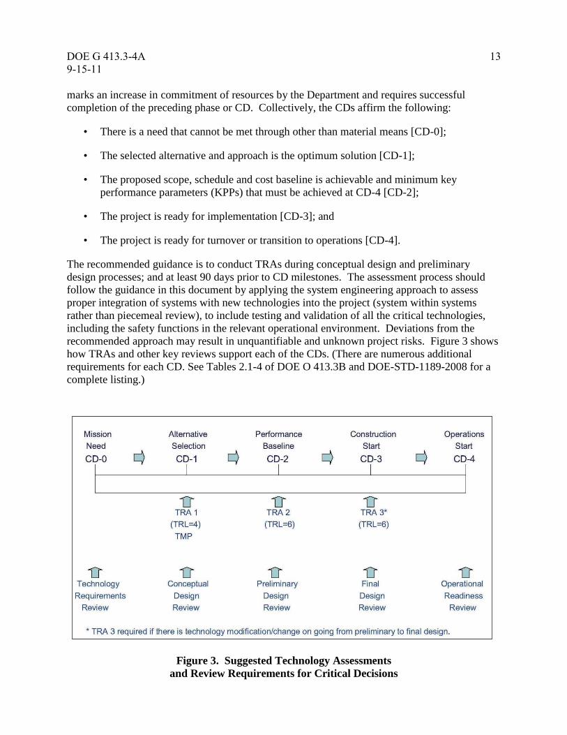
The recommended guidance is to conduct TRAs during conceptual design and preliminary
design processes; and at least 90 days prior to CD milestones. The assessment process should
follow the guidance in this document by applying the system engineering approach to assess
proper integration of systems with new technologies into the project (system within systems
rather than piecemeal review), to include testing and validation of all the critical technologies,
including the safety functions in the relevant operational environment. Deviations from the
recommended approach may result in unquantifiable and unknown project risks. Figure 3 shows
how TRAs and other key reviews support each of the CDs. (There are numerous additional
requirements for each CD. See Tables 2.1-4 of DOE O 413.3B and DOE-STD-1189-2008 for a
complete listing.)
Figure 3. Suggested Technology Assessments
and Review Requirements for Critical Decisions
14 DOE G 413.3-4A
9-15-11
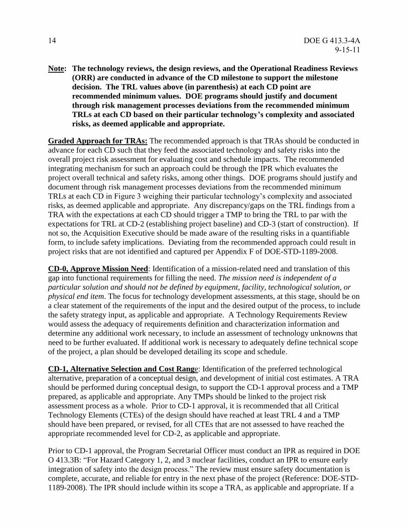
Note: The technology reviews, the design reviews, and the Operational Readiness Reviews
(ORR) are conducted in advance of the CD milestone to support the milestone
decision. The TRL values above (in parenthesis) at each CD point are
recommended minimum values. DOE programs should justify and document
through risk management processes deviations from the recommended minimum
TRLs at each CD based on their particular technology’s complexity and associated
risks, as deemed applicable and appropriate.
Graded Approach for TRAs: The recommended approach is that TRAs should be conducted in
advance for each CD such that they feed the associated technology and safety risks into the
overall project risk assessment for evaluating cost and schedule impacts. The recommended
integrating mechanism for such an approach could be through the IPR which evaluates the
project overall technical and safety risks, among other things. DOE programs should justify and
document through risk management processes deviations from the recommended minimum
TRLs at each CD in Figure 3 weighing their particular technology’s complexity and associated
risks, as deemed applicable and appropriate. Any discrepancy/gaps on the TRL findings from a
TRA with the expectations at each CD should trigger a TMP to bring the TRL to par with the
expectations for TRL at CD-2 (establishing project baseline) and CD-3 (start of construction). If
not so, the Acquisition Executive should be made aware of the resulting risks in a quantifiable
form, to include safety implications. Deviating from the recommended approach could result in
project risks that are not identified and captured per Appendix F of DOE-STD-1189-2008.
CD-0, Approve Mission Need: Identification of a mission-related need and translation of this
gap into functional requirements for filling the need. The mission need is independent of a
particular solution and should not be defined by equipment, facility, technological solution, or
physical end item. The focus for technology development assessments, at this stage, should be on
a clear statement of the requirements of the input and the desired output of the process, to include
the safety strategy input, as applicable and appropriate. A Technology Requirements Review
would assess the adequacy of requirements definition and characterization information and
determine any additional work necessary, to include an assessment of technology unknowns that
need to be further evaluated. If additional work is necessary to adequately define technical scope
of the project, a plan should be developed detailing its scope and schedule.
CD-1, Alternative Selection and Cost Range: Identification of the preferred technological
alternative, preparation of a conceptual design, and development of initial cost estimates. A TRA
should be performed during conceptual design, to support the CD-1 approval process and a TMP
prepared, as applicable and appropriate. Any TMPs should be linked to the project risk
assessment process as a whole. Prior to CD-1 approval, it is recommended that all Critical
Technology Elements (CTEs) of the design should have reached at least TRL 4 and a TMP
should have been prepared, or revised, for all CTEs that are not assessed to have reached the
appropriate recommended level for CD-2, as applicable and appropriate.
Prior to CD-1 approval, the Program Secretarial Officer must conduct an IPR as required in DOE
O 413.3B: “For Hazard Category 1, 2, and 3 nuclear facilities, conduct an IPR to ensure early
integration of safety into the design process.” The review must ensure safety documentation is
complete, accurate, and reliable for entry in the next phase of the project (Reference: DOE-STD-
1189-2008). The IPR should include within its scope a TRA, as applicable and appropriate. If a
DOE G 413.3-4A 15
9-15-11
DO
E G
413.3
-4
15
DR
AF
T X
X-X
X-0
9
safety system requires technology development, then it must be identified early or the objective
of credible technical scope, schedule, and cost baseline cannot be successfully achieved (note:
the activity is not optional, but the means to achieve the activity is optional).
CD-2, Performance Baseline: Completion of preliminary design, and development of a
performance baseline that contains a detailed scope, schedule, and cost estimate, and KPPs that
must be achieved at CD-4. The process of technology development, in accordance with the
program/project’s technology development plans and any TMPs issued as a result of a prior
TRA, should ensure that all CTEs have reached at least TRL 6, which indicates that the
technology is ready for insertion into detailed design, as applicable and appropriate. A TRA
should be performed at least 90 days prior to reaching CD-2 to independently assure that the
CTEs have in fact reached TRL 6 or the supportable recommended program/project’s target level
for CD-2, as applicable and appropriate. Projects are encouraged to achieve TRL 7 prior to CD-3
as a recognized best practice, but in no instance it is recommended that CD-2 be approved with a
TRL less than 6. In either case, the residual risks should be accounted in the Risk Management
Plan, recorded in the risk register and assigned the proper contingency in the project baseline
(see DOE G 413.3-7A).
Prior to CD-2 approval (refer to DOE O 413.3B), the PSO must conduct a TRA and develop a
TMP for major system projects where new critical technologies are being developed, as
appropriate.
CD-3, Start of Construction: Completion of essentially all design and engineering and
beginning of construction, implementation, procurement, or fabrication. A TRA is recommended
if there is a significant CTE modification subsequent to CD-2 as detailed design work
progressed. If substantial modification to a CTE occurs, the recommended TRA should be
performed and a TMP should be prepared or updated to ensure that the modified CTE will attain
TRL 6, prior to its insertion into the detailed design and baseline, as applicable and appropriate.
Prior to the start of operations, start-up testing and operational readiness reviews should ensure
that the CTEs have advanced to the target maturity level at CD-4 (TRL 6 toward TRL 9), as
applicable and appropriate.
Prior to CD-3 approval (refer to DOE O 413.3B), the PSO must conduct a TRA for major system
projects where a significant critical technology element modification occurs subsequent to CD-2.
CD-4, Start of Operations or Project Completion: Readiness to operate and/or maintain the
system, facility, or capability. Successful completion of all facility testing and entry into
operations corresponds to attainment of TRL 9. Nuclear and other hazardous operations may
have additional post CD-4 start-up requirements and qualifications that must be completed
before full operations begin under mission conditions.
2.2 Relationship of TRAs to Independent Project Reviews
IPRs are one of the measures that can be taken to ensure the timely resolution of engineering,
system integration, technology readiness assessments, design, quality assurance, operations, and
maintenance and nuclear/non-nuclear safety issues. It should also be emphasized that supporting
program issues and their resolution should also be reviewed under the IPR since they could

16 DOE G 413.3-4A
9-15-11
overshadow the technology development or other elements of the project, and as such, present an
element of uncertainty to the project. The purpose of an IPR is to assist reducing technical risk
and uncertainty which increases the probability of successful implementation of technical scope
including new technologies.
IPRs can include TRAs to provide an assessment of the maturity level of a new proposed
technology prior to insertion into the project design and execution phases to reduce technical risk
and uncertainty.
The TRA should not be considered a risk assessment, but it should be viewed as a tool for
assessing program risk and the adequacy of technology maturation planning by the
program/project. The TRA scores the current readiness level of selected system elements (i.e.,
CTEs), using defined TRLs (see section 4.0). The TRA highlights critical technologies and other
potential technology risk areas that may need the program manager/Federal Project Director
attention. If the system does not meet pre-defined TRL scores, then a CTE TMP should be
required. As discussed in section 5.0, this TMP explains in detail how the target TRL (the CTEs
maturity) will be advanced prior to the next milestone Critical Decision and it allows the
program/project to properly reflect the CTEs risk within the project’s baseline.
3.0 Model for Identifying Critical Technology Elements (CTEs)
The following definition of a CTE was adopted from the 2003 DoD, Technology Readiness
Assessment Deskbook, updated July 2009:
A technology element is “critical” if the system being acquired depends on this technology
element to meet operational requirements (with acceptable development cost and schedule and
with acceptable production and operation costs) and if the technology element or its application
is either new or novel, or in an area that poses major technological risk during design or
demonstration. Said another way, an element that is new or novel or being used in a new or
novel way is critical if it is necessary to achieve the successful development of a system, its
acquisition, or its operational utility.
Disciplined identification of CTEs is important to a program. The management
process/procedure for CTE identification is as important as the technical task because it adds to
the credibility of the resulting CTE list. If a CTE is overlooked and not brought by the
program/project to the requisite maturity level for later project insertion at the start of System
Design and Development, the system performance, program schedule, and cost could be
jeopardized. On the other hand, if an overly conservative approach is taken and a plethora of
technologies are categorized as critical, energy and resources are likely to be diverted from the
few technologies that deserve an intense maturation effort.
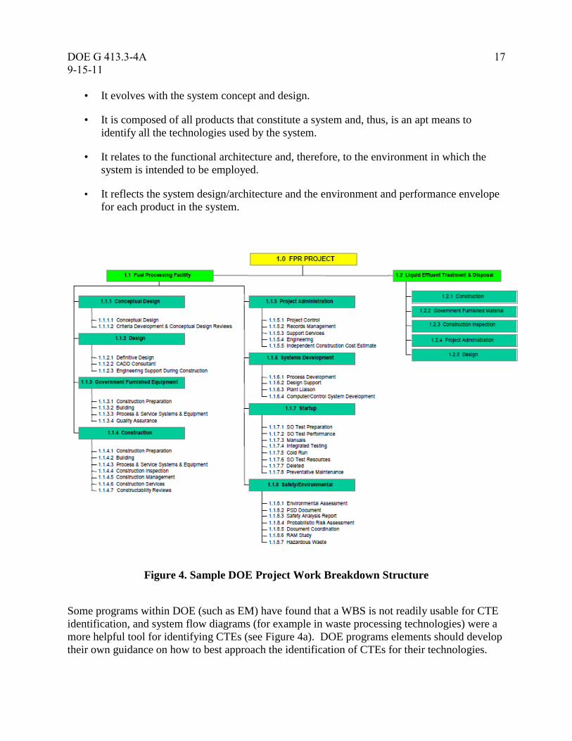
The Defense Acquisition Guidebook, updated July 2011, specifically recommends the use of the
Work Breakdown Structure (WBS) for a project to initially assist in identifying the CTEs (see
Figure 4 for a sample DOE project WBS). The WBS has several beneficial attributes for this
purpose:
• It is readily available when system engineering practices are used.
DOE G 413.3-4A 17
9-15-11
DO
E G
413.3
-4
17
DR
AF
T X
X-X
X-0
9
• It evolves with the system concept and design.
• It is composed of all products that constitute a system and, thus, is an apt means to
identify all the technologies used by the system.
• It relates to the functional architecture and, therefore, to the environment in which the
system is intended to be employed.
• It reflects the system design/architecture and the environment and performance envelope
for each product in the system.
Figure 4. Sample DOE Project Work Breakdown Structure
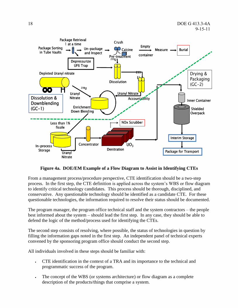
Some programs within DOE (such as EM) have found that a WBS is not readily usable for CTE
identification, and system flow diagrams (for example in waste processing technologies) were a
more helpful tool for identifying CTEs (see Figure 4a). DOE programs elements should develop
their own guidance on how to best approach the identification of CTEs for their technologies.
18 DOE G 413.3-4A
9-15-11
Figure 4a. DOE/EM Example of a Flow Diagram to Assist in Identifying CTEs
From a management process/procedure perspective, CTE identification should be a two-step
process. In the first step, the CTE definition is applied across the system’s WBS or flow diagram
to identify critical technology candidates. This process should be thorough, disciplined, and
conservative. Any questionable technology should be identified as a candidate CTE. For these
questionable technologies, the information required to resolve their status should be documented.
The program manager, the program office technical staff and the system contractors – the people
best informed about the system – should lead the first step. In any case, they should be able to
defend the logic of the method/process used for identifying the CTEs.
The second step consists of resolving, where possible, the status of technologies in question by
filling the information gaps noted in the first step. An independent panel of technical experts
convened by the sponsoring program office should conduct the second step.
All individuals involved in these steps should be familiar with:
CTE identification in the context of a TRA and its importance to the technical and
programmatic success of the program.
The concept of the WBS (or systems architecture) or flow diagram as a complete
description of the products/things that comprise a system.
Crush
Dissolution
Package Retrieval1 at a time
Un-packageand Inspect
Empty
container
Measure BurialPackage Sortingin Tube Vaults
Pre-treatment
Calcine
233
UDepleted Uranyl nitrate
Enrichment Down Blending
Interim Storage
ShieldedOverpack
DenitrationIn-process
Storage
NOx Scrubber
233U
238U
Inner Container
Uranyl Nitrate
Uranyl Nitrate
Uranyl Nitrate
Less than 1% fissile
UO3Concentrator
Package for Transport
Accountability
DepressurizeUF6 Trap
Dissolution & Downblending (GC-1)
Drying & Packaging (GC-2)
DOE G 413.3-4A 19
9-15-11
DO
E G
413.3
-4
19
DR
AF
T X
X-X
X-0
9
The distinction between hardware, software, and manufacturing technologies and the
metrics that evaluate their maturity (as described in Table 1 and section 4.0).
The affordability and production criteria for CTEs.
The role that “environment” has in identifying CTEs.
CTE Determination Criteria
The technical task in the second step involves the use of a series of questions to test whether the
CTE definition applies. The series of questions are divided in two sets of criteria:
(1) Criticality to program criteria, and
(2) New or novel criteria.
Appendix E presents a sample template for the series of questions suggested for determining
whether a technology element is a CTE. It is advisable that this template be completed for each
candidate CTE so that a formal record of the CTE determination can be maintained by the
project.
For a technology to be critical, the answer to one of the following questions should be “yes”:
Criticality to Program Criteria
Does the technology directly impact a functional requirement of the process or facility?
Do the limitations in the understanding of the technology result in a potential schedule
risk; i.e., the technology may not be ready for insertion when required?
Do limitations in the understanding of the technology result in a potential cost risk; i.e.,
the technology may cause significant cost overruns?
Do limitations in the understanding of the technology impact the safety of the design?
Are there uncertainties in the definition of the end state requirements for this technology?
In addition, the answer to one of the following questions should also be “yes”:
New or Novel Criteria
Is the technology new or novel?
Is the technology modified?
Have the potential hazards of the technology been assessed?
Has the technology been repackaged so that a new relevant environment is realized?
20 DOE G 413.3-4A
9-15-11
Is the technology expected to operate in an environment and/or achieve a performance
beyond its original design intention or demonstrated capability?
The environment in which the system will operate plays a significant role in answering these last
four questions. Generally, the requirement statement for the system will provide some
description of the environment in which the system is expected/required to operate. This can be
called the external or imposed environment. It may be natural or man-made, friendly or hostile
(e.g., weather, terrain and hostile jamming, terrorism, and so forth). Another environment – the
one generally more important for identifying and evaluating CTEs – can be called internal or
realized environment. It is derived from the performance required of each design item (product,
subsystem, component, WBS element). The design analysis should include the required or
expected performance envelope and conditions for each WBS or flow diagram technology
element.
A complete definition of the operational environment for the system and its components is
necessary to determine that the planned environment is identical to prior applications where this
technology has been successfully used. Deviations between the planned environment and the
environment of prior applications results in the need to qualify (mature) the planned use of the
technology by the program/project.
People with the requisite technical knowledge and the independence needed to make a good
judgment should guide the actual set of questions asked for each CTE candidate. The program
manager and the suppliers should present clear, convincing, and succinctly summarized data that
show what is known/not known about the environment and should explain the similarities and
dissimilarities between the expected/demonstrated environments.
4.0 Model for Technology Readiness Level Assessments
Determination of a TRL should be conducted by the program/project as part of normal project
planning and development early in the project, and assessed by a TRA team of independent
project experts prior to key critical decisions. Both the project and the TRA team can use the
following process:
TRL is a measure used by some United States government agencies (sometimes as a direct result
of Congressional direction) and many of world’s major companies (and agencies) to assess the
maturity of evolving technologies (materials, components, devices, etc.) prior to incorporating
that technology into a system or subsystem. Generally speaking, when a new technology is first
invented or conceptualized, it is not suitable for immediate application. Instead, new
technologies are usually subjected to experimentation, refinement, and increasingly realistic
testing. Once the technology is sufficiently proven or matured, it can be incorporated into a
system/subsystem. TRL at its most basic definition describes the maturity of a given technology
relative to its development cycle.
Technology maturity is a measure of the degree to which proposed CTEs meet program
objectives and can be related to program risk. A TRA examines program concepts, technology
requirements, and demonstrated technology capabilities including the safety function, in order to
determine technological maturity. Table 4 provides a summary view of the technology
DOE G 413.3-4A 21
9-15-11
DO
E G
413.3
-4
21
DR
AF
T X
X-X
X-0
9
maturation process model adopted from NASA and DoD, and somewhat modified by DOE-EM,
which could be tailored for use by other DOE programs. This DOE-wide model has the
following attributes: it includes (a) “basic” research in new technologies and concepts (targeting
identified goals, but not necessarily specific systems), (b) focused technology development
addressing specific technologies for one or more potential identified applications, (c) technology
development and demonstration for each specific application before the beginning of full system
development of that application, (d) early identification of all potential hazards from the
technology and the testing of the safety functions in the relevant environment, (e) system
development (through first unit fabrication), and (f) system “launch” and operations.
Hazard Analysis/Safety: Design and performance requirements for CTEs should address hazards
early to ensure safety is “designed in” early instead of “added on” later with increased cost and
decreased effectiveness. Analysis of hazards results in the identification of potential accident
scenarios and the determination of how to prevent or mitigate accidents. Safety Structures,
Systems and Components (SSCs) are identified and incorporated into the design to prevent or
mitigate the consequences of hazards to the facility worker, the collocated worker and the public.
These SSCs are classified as safety class, safety significant or defense in depth as required by
their safety function. Testing and validation of safety functions in the relevant environment for
the CTEs is part of the TRA, as applicable and appropriate. (Reference: DOE O 420.1B and
DOE O 413.3B]

22 DOE G 413.3-4A
9-15-11
Table 4. DOE Technology Readiness Level Scale

DOE G 413.3-4A 23
9-15-11
DO
E G
413.3
-4
23
DR
AF
T X
X-X
X-0
9
The TRL scale used in Table 4 requires that testing of a prototypical design in a relevant
environment be completed prior to incorporation of the technology into the final design of the
facility. All technology readiness levels should include compliance with DOE-STD-1189-2008
and DOE O 413.3B to include worker and public safety considerations early in the design
process.
The testing performed on the CTEs to demonstrate its operational capability and performance is
compared to the TRLs in Table 5 (DOE/EM application). The TRL definitions provide a
convenient means to understand further the relationship between the scale of testing, fidelity of
testing system, and testing environment and the TRL. This scale requires that for a TRL 6
testing should be completed at an engineering or pilot scale, with a testing system fidelity that is
similar to the actual application. Table 6 provides additional definitions of the TRL descriptive
terms often used by DoD in the testing recommendations for TRLs for some of their
technologies.
Table 5. DOE/EM Relationship of Testing Recommendations to the TRL

24 DOE G 413.3-4A
9-15-11
Table 6. Additional Definitions of TRL Descriptive Terms (Source: Defense Acquisition Guidebook)
The primary purpose of using the above Technology Readiness Level definitions (Levels 1
through 9) is to help management in making decisions concerning the development and
maturation of technology to ensure it can perform its intended mission. Advantages include:
Provides a common standard for systematically measuring and communicating the
readiness of new technologies or new applications of existing technologies at a given
point in time in the project life cycle.
DOE G 413.3-4A 25
9-15-11
DO
E G
413.3
-4
25
DR
AF
T X
X-X
X-0
9
Provides a measure of risk as a management tool. The gap between the maturity of the
technology and the project requirements represents the risks or unknowns about the
technology.
Assist in making decisions concerning technology funding.
Assist in making decisions concerning transition of technology.
Assist in selecting the best technology alternative.
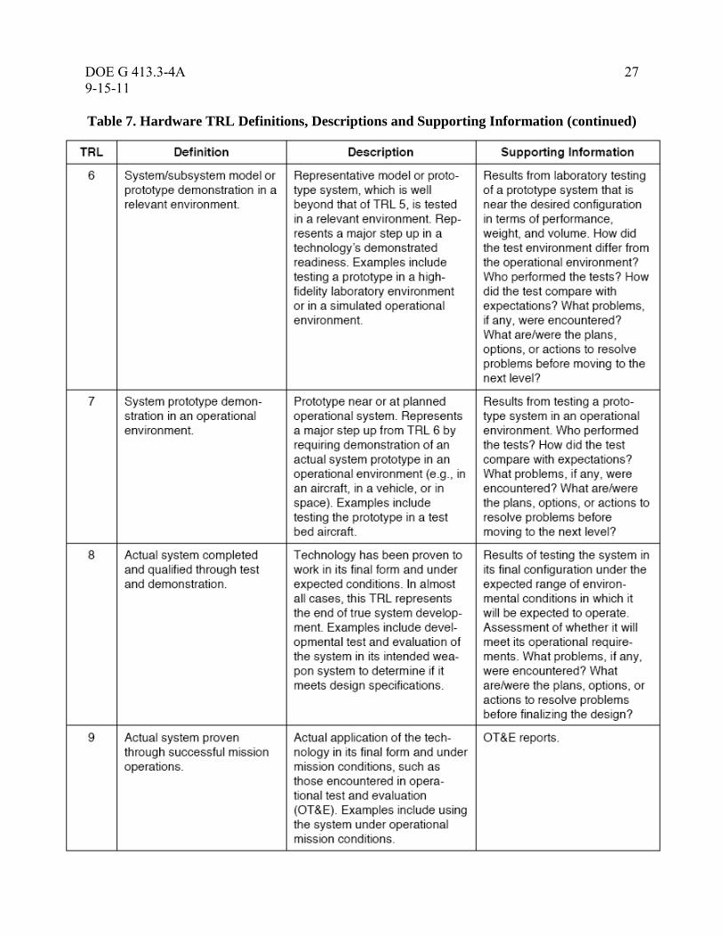
4.1 Supporting Documentation for the Technology Readiness Levels Assessments
Table 7 lists typical generic documentation (not all inclusive and varies by technology
application and program) that should be extracted or referenced to support a TRL assignment.

26 DOE G 413.3-4A
9-15-11
Table 7. Hardware TRL Definitions, Descriptions and Supporting Information (Source: Defense Acquisition Guidebook)
DOE G 413.3-4A 27
9-15-11
DO
E G
413.3
-4
27
DR
AF
T X
X-X
X-0
9
Table 7. Hardware TRL Definitions, Descriptions and Supporting Information (continued)

28 DOE G 413.3-4A
9-15-11
4.2 CTEs Assessments for Maturity (Technology Readiness Level)
The evaluation process should include the following steps for all CTEs (Reference: DoD
Technology Readiness Assessment Deskbook, July 2009):
Describe the technology (subsystem, component, or technology). Describe the function it
performs and, if needed, how it relates to other parts of the system. Provide a synopsis of
development history and status. This can include facts about related uses of the same or
similar technology, numbers or hours of testing of breadboards, numbers of prototypes
built and tested, relevance of the test conditions, and results achieved.
Describe the environment in which the technology has been demonstrated. Provide a
brief analysis of the similarities between the demonstrated environment and the intended
operational environment.
Apply the criteria for TRLs and assign a readiness level to the technology. State the
readiness level (e.g., TRL 5) and the rationale for choosing this readiness level.
Provide references to papers, presentations, data, and facts that support the assessment.
Includes data tables and graphs that illustrate that a key fact is appropriate.
If the CTEs are presented in categories (e.g., super-conducting magnets, detectors or
sensors), the information specified in the previous bullets (e.g., describing the
technology, describing the function it performs, and so forth) should be provided for each
CTE within a category.
State the review team’s position concerning the maturity (technology readiness level) of
the CTEs and whether this maturity is adequate for the system to enter the next stage of
development. If the position supports entering the next stage even though some CTEs are
less mature than would ordinarily be expected, explain what circumstances or planned
work justifies this position. Include references to a separately submitted Technology
Maturation Plan (see section 5.0) for each immature CTE.
4.3 Technology Readiness Level Calculator
The TRL Calculator is a tool developed by the US Air Force Research Laboratory for applying
TRLs for technology development programs (Reference: Nolte, William L., et al., “Technology
Readiness Level Calculator,” October 20, 2003, Air Force Research Laboratory (AFRL),
presented at the NDIA System Engineering Conference). In its present form, the calculator is a
Microsoft Excel spreadsheet application that allows the user to answer a series of questions about
a technology project. Once the questions have been answered, the calculator displays the TRL
achieved. Because the same set of questions is answered each time the calculator is used, the
calculator provides a standardized, repeatable process for evaluating the maturity of any
hardware or software technology under development. In this way, the TRL Calculator is one
tool that can serve to answer the question of how one can measure TRLs for CTEs using a
standardized method.

DOE G 413.3-4A 29
9-15-11
DO
E G
413.3
-4
29
DR
AF
T X
X-X
X-0
9
The present version of the calculator is limited to values of TRLs corresponding to TRL 6 or
lower. This is because, in the Air Force Research Laboratory, the stated objective of a
technology development program is to mature the technology to TRL 6. While it is certainly
possible to mature a given technology beyond that level, there are no purely programmatic
activities that take place within the laboratory beyond TRL 6. Because the calculator was
initially created for use in the laboratory, a TRL 6 was deemed sufficient. Extending the TRL
concept to a level corresponding to TRL 9 is the subject of future work by the original
developers of the tool. (A copy of the latest version of the US Air Force’s TRL Calculator can
be obtained directly for William Nolte at the AFRL.)
A modified version of the DoD TRL Calculator has been used extensively during the conduct of
DOE-EM TRAs and is included in Appendix F as an example of a tailored version. DOE
programs should adapt/modify the suggested calculator to their particular technologies and
processes. The TRL Calculator herein is used in a two step process. First, a set of top-level
questions (Table F1 of Appendix F) is used to determine the anticipated TRL. The anticipated
TRL is determined from the question with the first “yes” answer. Second, evaluation of the
detailed questions (Tables F2 through F7 of Appendix F) is started one level below the
anticipated TRL. To attain a specific TRL, the CTE should receive a “yes” response to all
questions at the TRL level from which the questions are found. If it is determined from the
detailed questions that the technology has not attained the maturity of the starting level, then the
next levels down are evaluated in turn until all of the questions for a specific TRL are answered
“yes”. The TRL is defined by the level from which all questions are answered affirmatively.
However, it is recognized that a negative response to one single question for the TRL under
evaluation might not be indicative of the relative importance of the particular item to the success
of the technology. In this instance a graded approach could be appropriate during the evaluation
and justified when assigning the highest TRL number achieved for the technology. TRL
calculators are expected to evolve over time based upon lessons learned from previous versions
of calculators used by the programs.
TRLs are documented within the TRA Report. As a minimum, the TRL should be expressed
numerically and described in text. Additionally, the basis for the TRL determination should be
clearly and concisely documented. DOE/EM has found that completing the forms found in
Appendix F for all CTEs serves to document the basis for the TRL decision.
4.4 TRA Report
The purpose of the TRA Report is to document the description of the process used to conduct the
TRA and provide a comprehensive explanation of the assessed TRL for each CTE. While the
Appendix F forms document the answers to the questions, the basis for these answers is what the
report should focus on. The report should provide citation to and summary descriptions of the
salient aspects of the reference documents which serve the basis for the answers documented in
the forms.
The TRA review team leader is responsible for coordinating the report preparation with detailed
input from the review team members (see DOE G 413.3-9 for the protocol to conduct project
reviews of which TRA reviews is one under the category of Technical IPRs; Appendix D is the

30 DOE G 413.3-4A
9-15-11
suggested template for a TRA Review Plan). See Appendix G for the suggested format of the
report. As a minimum, completion of the TRA should provide:
• A comprehensive review, using an established program/project Work Breakdown
Structure or flow diagram as an outline, of the entire platform or system. This review,
using a conceptual or established baseline design configuration, identifies CTEs.
• An objective scoring of the level of technology maturity for each CTE by subject matter
experts.
• Results should assist the Integrated Project Team in preparing maturation plans for
achieving an acceptable maturity roadmap for CTEs prior to critical milestones decision
dates.
• A final report documenting the findings of the assessment review team.
• Continuous improvement is an important part of an evolving TRA process and as such
lessons learned that benefit future TRAs and/or technology development projects should
be identified during the conduct of the TRA. These lessons learned should be
documented within the TRA Report or they may be documented in a separate document.
In the case of a separate lessons learned document, the TRA report should be referenced
within the document and the document should be filed with the TRA Report.
A TRA team should plan to reference relevant portions of the project’s report in developing its
own report.
5.0 Technology Maturation Plan
5.1 Process Overview
The purpose of the TMP is to describe planned technology development and engineering
activities to mature CTEs that did not receive at least TRL 6 or higher. This threshold should be
a DOE Program level option tailored to their specific technologies, as required and appropriate.
TRL 6 is the recommended standard for advancing from the conceptual design phase to the
design finalization phase due to the vast amount of industry, DoD and NASA experience that
shows that unless a technology has been advanced to this level of maturity at the time of CD- 2
(project baseline) approval, the potential for baseline performance deviations is so great and the
later corrective actions so disruptive and costly to the project that proper project management
control cannot be expected to be successful at bringing the project to completion within the
originally approved technical, cost and schedule baselines. DOE-EM has adopted a level 6
during their most recent TRAs in their effort to reduce the probability of cost and schedule
overruns due to immature CTEs.
The program/project should be beginning the development of its TMP subsequent to the
approval of the project’s mission need at CD-0. As a result of conducting a TRA, the project
may be required to revise its TMP in order to address and remedy TRL deficiencies noted in a
TRA report. TRA induced changes to TMPs can be likened to a corrective action plan in that the
DOE G 413.3-4A 31
9-15-11
DO
E G
413.3
-4
31
DR
AF
T X
X-X
X-0
9
changes to the TMP are prepared by the project and describes the additional or corrective actions
for those CTEs that did not mature as the project had intended [because they did not received the
desired TRL by the time the associated critical decision was reached (i.e., for example CD-1,
TRL=4; CD-2, TRL=6)].
5.2 TMP Preparation
The suggested major steps in preparing a TMP are summarized below (each DOE Program
Office should develop its own protocol for concurrences and approvals of this documentation):
• The Project Manager/Contractor prepares the draft TMP. The suggested format and
contents of the document are provided below and in Appendix H.
• At CD-0 and thereafter as appropriate, the Project Manager for the project provides the
draft report to the Federal Project Director and the DOE Program Office for review and
approval. To expedite the schedule, these reviews are often accomplished in parallel.
• If the project is modifying a TMP in response to a TRA, after approval by the
program/project, the TMP is provided to the TRA review team for review. The review
verifies (1) responsiveness to gaps identified in the draft TRA, (2) reasonableness of the
proposed approach, and (3) reasonableness of the proposed schedule and costs associated
with technology maturation requirements.
Note: The Project Manager should have updated a TMP prior to the TRA review team visit,
anticipating the necessary changes based on the project’s own internal program reviews of its
technology maturation status.
• As applicable, the Project Manager resolves the review comments, revises the TMP, and
forwards the revised TMP to the Federal Project Director.
• The Federal Project Director approves the final TMP.
• The Federal Project Director incorporates the impact of changes in the project’s TMP
into the project risk management plan.
As described in Appendix H, the TMP revision should summarize any previous TIPRs, other
technical assessments, and any previous TRAs that may have contributed to the need for the
revision of the document. This summary should include the TRLs for each CTE as documented
in the latest TRA. Previous technology development activities that brought the technology to its
current state of readiness should be described. Also, ongoing technology development should be
included because progress and completion of this ongoing work will influence the interfaces and
schedule for the TMP. The TMP should describe the approach used in defining the additional
required technology development activities that will be conducted. Approaches may include
evaluating incomplete criteria in the TRL calculator, risk assessments, and value engineering.
In preparing the TMP for relatively mature technologies, TRA results should be evaluated using
a risk evaluation and value engineering approach. Figure 5 provides a diagram of the technology
maturation planning process. An identified technology readiness issue (or technology need) is
32 DOE G 413.3-4A
9-15-11
evaluated using the system engineering functions and requirement analysis. Then, a first order of
risk evaluation is conducted to determine whether the current path can be followed with
negligible risk or if alternatives (current path with modifications or a new system) should be
pursued. A more detailed, second order risk evaluation is conducted to determine if the
modifications or new system alternatives have sufficient payoff to be incorporated into the TMP.
In describing the required technology development activities, specific maturation plans should be
prepared for each CTE assessed at less than TRL 6 (threshold option for the DOE Program
Office to decide). The plan for each CTE should include:
Key Technology Addressed
Objective
Current State of the Art
Technology Development Approach
Scope
Schedule
Budget
The high-level schedule and budget (including the total maturation costs) that incorporate the
major technology development activities for each CTE should be provided. Any major decision
points such as proceeding with versus abandoning the current technology or selection of a
backup technology should be included in the schedule. More detailed schedules will be prepared
for executing and managing the work.
5.3 TMP Execution
After the TMP is approved, the Contractor will prepare or modify detailed test plans to conduct
the technology development activities described in the TMP. These test plans will define the test
objectives, relevant environment, the scale of the planned tests, and performance targets (or
success criteria) for the tests. Then, more detailed cost and schedule estimates will be prepared
by the Contractor to support preparation of a Baseline Change Proposal (BCP), if required. The
BCPs will be approved in accordance with the approved Project Execution Plan or as directed by
the DOE Program Office when outside the project scope.
The Contractor may conduct the technology development in house or work with DOE to select a
technology developer by open procurements to industry, identification of national laboratories
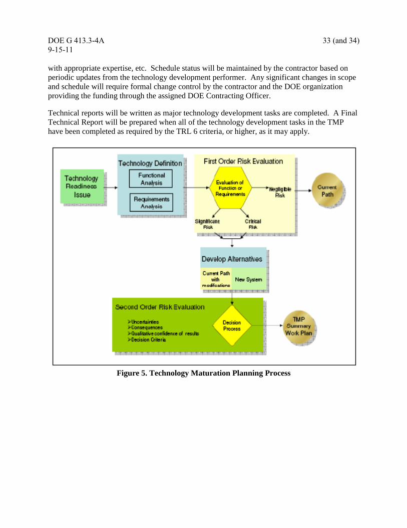
DOE G 413.3-4A 33 (and 34)
9-15-11
DO
E G
413.3
-4
33
DR
AF
T X
X-X
X-0
9
with appropriate expertise, etc. Schedule status will be maintained by the contractor based on
periodic updates from the technology development performer. Any significant changes in scope
and schedule will require formal change control by the contractor and the DOE organization
providing the funding through the assigned DOE Contracting Officer.
Technical reports will be written as major technology development tasks are completed. A Final
Technical Report will be prepared when all of the technology development tasks in the TMP
have been completed as required by the TRL 6 criteria, or higher, as it may apply.
Figure 5. Technology Maturation Planning Process


DOE G 413.3-4A Appendix A
9-15-11 A-1
APPENDIX A: GLOSSARY
1. Acquisition Executive. The individual designated by the Secretary of Energy to
integrate and unify the management system for a program portfolio of projects and
implement prescribed policies and practices.
2. Breadboard. Integrated components that provide a representation of a system/subsystem
and that can be used to determine concept feasibility and to develop technical data.
Typically it is configured for laboratory use to demonstrate the technical principles of
immediate interest. It may resemble the final system/subsystem in function only.
3. Critical Technology Element (CTE). A technology element is “critical” if the system
being acquired depends on the technology element to meet operational requirements
(with acceptable development, cost and schedule; and with acceptable production and
operations costs) and if the technology element or its application is either new or novel.
4. External Independent Review. A project review performed by personnel from OECM
and augmented by individuals outside DOE, primarily to support validation of either the
Performance Baseline (CD-2) or Construction/Execution Readiness (CD-3). OECM
selects an appropriate group of subject matter experts in a contracted capacity to assist
with these reviews.
5. High Fidelity. A representative of the component or system that addresses form, fit and
function. A high-fidelity laboratory environment would involve testing with equipment
that can simulate and validate all system specification within a laboratory setting.
6. Independent Cost Estimate. A cost estimate, prepared by an organization independent
of the project sponsor, using the same detailed technical and procurement information to
make the project estimate. It is used to validate the project estimate to determine
whether it is accurate and reasonable.
7. Independent Cost Review. An independent evaluation of a project’s cost estimate that
examines its quality and accuracy, with emphasis on specific cost and technical risks. It
involves the analysis of the existing estimate’s approach and assumptions.
8. Independent Project Review. A project management tool that serves to verify the
project’s mission, organization, development, processes, technical requirements,
baselines, progress and/or readiness to proceed to the next successive phase in DOE’s
Acquisition Management System.
9. Key Performance Parameter (KPP). A vital characteristic, function, requirement or
design basis, that if changed, would have a major impact on the facility or system
performance, scope, schedule, cost and/or risk, or the ability of an interfacing project to
meet its mission requirements. A parameter may be a performance, design, or interface
requirement. Appropriate parameters are those that express performance in terms of

Appendix A DOE G 413.3-4A
A-2 9-15-11
accuracy, capacity, throughput, quantity, processing rate, purity, reliability,
sustainability, or others that define how well a system, facility or other project will
perform. In aggregate, KPPs comprise the scope of the project.
10. Low Fidelity. A representative of the component or system that has limited ability to
provide anything but first-order information about the end product. Low fidelity
assessments are used to provide trend analysis.
11. Operational Environment. Environment that addresses all the operational requirements
and specifications required of the final system to include platform/packaging.
12. Project Definition Rating Index. This is a project management tool which is used for
assessing how well the project scope is defined. The tool uses a numeric assessment
which rates a wide range of project elements to determine how well the project is
defined.
13. Relevant Environment. Testing environment that simulates the key aspects of the
operational environment; such as physical and chemical properties.
14. Simulated Operational Environment. Either (1) a real environment that can simulate all
the operational requirements and specifications required of the final system or (2) a
simulated environment that allows for testing of a virtual prototype. Used in either case
to determine whether a developmental system meets the operational requirements and
specifications of the final system.
15. Technical Independent Project Review. An independent project review conducted prior
to obtaining CD-2 for Hazard Category 1, 2, and 3 nuclear facilities. At a minimum, the
focus of this review is to determine that the safety documentation is sufficiently
conservative and bounding to be relied upon for the next phase of the project.
16. Technology Maturation Plan. A TMP details the steps necessary for developing
technologies that are less mature than desired to the point where they are ready for
project insertion.
17. Technology Readiness Assessment. An assessment of how far technology development
has proceeded. It provides a snapshot in time of the maturity of technologies and their
readiness for insertion into the project design and execution schedule.

DOE G 413.3-4A Appendix A
9-15-11 A-3 (and A-4)
18. Technology Readiness Level. A metric used for describing technology maturity. It is a
measure used by many U.S. government agencies to assess maturity of evolving
technologies (materials, components, devices, etc.) prior to incorporating that technology
into a system or subsystem.
19. Technology Readiness Level Calculator. A tool developed by the U.S. Air Force
Research Laboratory for applying TRLs to technology development programs. In its
present stage of development, the calculator is a Microsoft Excel spreadsheet
application that allows the user to answer a series of questions about a technology
project. Once the questions have been answered, the calculator displays the TRL
achieved.

DOE G 413.3-4A Appendix B
9-15-11 B-1
APPENDIX B: ACRONYMS
AE Acquisition Executive
CD Critical Decision
CDR Conceptual Design Report
CFR Code of Federal Regulations
CO Contracting Officer
CY Calendar Year
DoD U.S. Department of Defense
DOE U.S. Department of Energy
CTE Critical Technology Element
EIR External Independent Review
EIS Environmental Impact Statement
EM Environmental Management
EPA U.S. Environmental Protection Agency
ESAAB Energy Systems Acquisition Advisory Board
EVMS Earned Value Management System
FAR Federal Acquisition Regulations
FONSI Finding of No Significant Impact
FPD Federal Project Director
FY Fiscal Year
GAO Government Accountability Office
GPRA Government Performance and Results Act
HA Hazard Assessment
ICE Independent Cost Estimate
ICR Independent Cost Review
IMS Integrated Master Schedule
IOC Initial Operating Capability
IPR Independent Project Review
IPS Integrated Project Schedule
IPT Integrated Project Team
ICE Independent Cost Estimate
IPR Independent Project Review
ISM Integration Safety Management
ISMS Integrated Safety Management System
Appendix B DOE G 413.3-4A
B-2 9-15-11
ISO International Standards Organization
IT Information Technology
KPP Key Performance Parameter
MNS Mission Need Statement
MS Major System Project
NASA National Aeronautics and Space Administration
NEPA National Environmental Policy Act
NNSA National Nuclear Security Administration
NQA-1 Nuclear Quality Assurance Standard – 1 (ANSI/ASME standard)
NRC National Research Council
OBS Organizational Breakdown Structure
OECM Office of Engineering and Construction Management
OMB Office of Management and Budget
OPC Other Project Costs
ORR Operational Readiness Review
OSHA Occupational Safety and Health Administration
PARS Project Assessment and Reporting System
PB Performance Baseline
PBC Performance-Based Contract
PBS Performance Baseline Summary
PDS Project Data Sheet
PED Project Engineering and Design
PEP Project Execution Plan
PM Program Manager
PMB Performance Measurement Baseline
PPBES Planning, Programming, Budgeting and Execution System
PSO Program Secretarial Office
PMSO Project Management Support Office
QA Quality Assurance
QAP Quality Assurance Plan
QAPP Quality Assurance Program Plan
QC Quality Control
RAMI Reliability, Accessibility, Maintainability, Inspectability
RCRA Resource Conservation and Recovery Act
DOE G 413.3-4A Appendix B
9-15-11 B-3 (and B-4)
RD Requirements Document
RFP Request for Proposal
RLS Resource Loaded Schedule
SAE Secretarial Acquisition Executive
TEC Total Estimated Cost (Capital)
TIPR Technical Independent Project Review
TPC Total Project Cost
TRA Technology Readiness Assessment
TMP Technology Maturation Plan
TRL Technology Readiness Level
VM Value Management
WBS Work Breakdown Structure
WA Work Authorization

DOE G 413.3-4A Appendix C
9-15-11 C-1
APPENDIX C: REFERENCES
10 CFR 830, Subpart A, Quality Assurance Requirements.
10 CFR 830, Subpart B, Safety Basis Requirements.
10 CFR 830.206, Preliminary Documented Safety Analysis.
29 CFR 1910.119, Process Safety Management of Highly Hazardous Chemicals.
48 CFR 970.5223-1, Integration of Environment. Safety, and Health into Work Planning and
Execution.
DOE O 205.1B, Department of Energy Cyber Security Program, dated 5-16-11.
DOE O 413.3B, Program and Project Management for the Acquisition of Capital Assets, dated
11-29-10.
DOE O 414.1D, Quality Assurance, dated 4-25-11.
DOE O 420.1B, Facility Safety, dated 12-22-05.
DOE O 425.1D, Verification of Readiness to Start-Up or Restart Nuclear Facilities, dated
4-16-10.
DOE O 436.1, Departmental Sustainability, dated 5-02-11.
DOE O 451.1B Chg 2, National Environmental Policy Act Compliance Program, dated 6-25-10.
DOE P 226.1B, Department of Energy Oversight Policy, dated 4-25-11.
DOE P 470.1A, Safeguards and Security Program, dated 12-29-10.
DOE P 450.4A, Integrated Safety Management Policy, dated 4-25-11.
DOE-STD-1189-2008, Integration of Safety into the Design Process, dated April 2008
DOE-STD-3006-2010, Planning and Conduct of Operational Readiness Reviews (ORR), dated
year 2010.
DOE M 470.4B, Safeguards and Security Programs, dated 7-21-11.
DOE G 413.3-9, DOE Project Review Guide for Capital Asset Projects, dated 9-23-08.
DOE G 413.3-7A, Risk Management Guide, dated 01-08-11
ANSI-EIA-649, National Consensus Standard for Configuration Management.

Appendix C DOE G 413.3-4A
C-2 9-15-11
Department of Defense, Technology Readiness Assessment (TRA) Deskbook, prepared by the
Deputy Undersecretary of Defense for Science and Technology, July 2009.
DOE, SPD-07-195, Aiken, South Carolina, Savannah River Site Tank 48H Waste Treatment
Project, Technology Readiness Assessment, dated July 2009.
DOE, Office of Engineering and Construction Management (OECM), External Independent
Review (EIR), Standard Operating Procedure (SOP), dated July 2008.
DOE, Office of Engineering and Construction Management (OECM), Root Cause Analysis
Contract and Project Management, April 2008.
DOE, Office of Engineering and Construction Management (OECM), Root Cause Analysis
Contract and Project Management, Corrective Action Plan, July 2008.
DOE, Office of Environmental Management, Project Definition Rating Index (EM-PDRI)
Manual, Revision 1, dated February 2001.
DOE, Office of Management, Budget and Evaluation, Reviews, Evaluations, and Lessons
Learned, Rev E, dated June 2003.
DOE, Office of River Protection, Richland, Washington, Technology Readiness Assessment
for the Waste Treatment and Immobilization Plant (WTP) Analytical Laboratory, Balance of
Facilities and LAW Waste Vitrification Facilities, dated March 2007.
DOE, Office of Science, Independent Review Handbook, dated May 2007.
House Report 109-86, Energy and Water Development Appropriations Bill, 2006.
GAO-07-336, Report to the Subcommittee on Energy and Water Development, and Related
Agencies, Committee on Appropriations, House of Representatives, DOE Major
Construction Projects Need a Consistent Approach for Assessing Technology Readiness to Help
Avoid Cost Increases and Delays, dated March 2007.
GAO/NSIAD-99-162, Best Practices: Better Management of Technology Can Improve Weapon
Systems Outcomes, July 1999, US General Accounting Office.
National Research Council, Improving Project Management in the Department of Energy,
1999.
National Research Council, Progress in Improving Project Management in the Department of
Energy, 2001.
DOE G 413.3-4A Appendix C
9-15-11 C-3 (and C-4)
National Research Council, Progress in Improving Project Management in the Department of
Energy, 2003.
National Research Council, Assessment of the Results of External Independent Reviews for U.S.
Department of Energy Projects, 2007.
NNSA Policy Letter: BOP-50.003, Establishment of NNSA Independent Project Review Policy,
dated June 2007.
NNSA, Office of Project Management and System Support, Project Definition Rating Index
(PDRI) Manual, Revision 0, dated June 2008.
Nolte, William L., et al., Technology Readiness Level Calculator, Air Force Research
Laboratory, presented at the National Defense Industrial Association Systems Engineering
Conference, October 20, 2003


DOE G 413.3-4A Appendix D
9-15-11 D-1 (and D-2)
APPENDIX D: TEMPLATE FOR A
TECHNOLOGY READINESS ASSESSMENT (TRA) REVIEW PLAN
1.0 INTRODUCTION
Briefly state who requested the TRA, what organization is responsible for conducting the
TRA, and what technology is to be assessed. State where the technology is being
developed (i.e., facility, site).
2.0 PURPOSE
Briefly state the objective of the TRA. Specifically, state how the customer will use the
results from the TRA. Additionally, state any other drivers for conduct of the TRA (e.g.,
Critical Decision milestone support, technology downselect support).
3.0 TECHNOLOGY BACKGROUND
Provide a general description of the technology and the project supported by the
technology. The description should include details regarding the function that the
technology accomplishes for the project and a brief summary of status of the technology
development. Additionally, summarize the results of any previous TRAs conducted on the
technology.
4.0 TRA TEAM
Include a table that lists the position, title, name and area of expertise of each TRA Team Member
Position Title Company Name Area of Expertise
Team Leader Person 1 Title Person 1 company Person 1 name Person 1 expertise
Team Member Person 2 Title Person 2 company Person 2 name Person 2 expertise
Team Member Person 3 Title Person 3 company Person 3 name Person 3 expertise
Team Member Person 4 Title Person 4 company Person 4 name Person 4 expertise
5.0 TRA ESTIMATED SCHEDULE (conservative Projected Durations which may vary by project
complexity)
Task
Number
Projected Duration Task Description
1 6 weeks Establish TRA Team
2 4 weeks Distribute critical documents to Team
3 4 weeks Conduct onsite assessment activities
4 4 weeks Draft TRA Report
5 4 weeks Issue Final Report
6.0 TRA ESTIMATED COST
Provide an estimate of the total man-hours and associated cost for conduct of the TRA.
Additionally, state the organization responsible for funding the TRA.
7.0 DEFINITIONS
8.0 REFERENCES
Appendices


DOE G 413.3-4A Appendix E
9-15-11 E-1 (and E-2)
APPENDIX E: TEMPLATE FOR THE IDENTIFICATION OF
CRITICAL TECHNOLOGY ELEMENTS (CTEs)
A CTE is identified if there is at least one positive response for each set of criteria
Set 1 - Criteria Yes No
1. Does the technology directly impact a functional requirement of the process
or facility?
2. Do limitations in the understanding of the technology result in a potential
schedule risk, i.e., the technology may not be ready for insertion when
required?
3. Do limitations in the understanding of the technology result in a potential
cost risk; i.e., the technology may cause significant cost overruns?
4. Do limitations in the understanding of the technology impact the safety of
the design?
5. Are there uncertainties in the definition of the end state requirements for this
technology?
Set 2 - Criteria Yes No
1. Is the technology new or novel?
2. Is the technology modified?
3. Have the potential hazards of the technology been assessed?
4. Has the technology been repackaged so a new relevant environment is
realized?
5. Is the technology expected to operate in an environment and/or achieve
performance beyond its original design intention or demonstrated capability?


DOE G 413.3-4A Appendix F
9-15-11 F-1
Appendix F: Template Examples for the TRL Assessment Calculator as Modified for
DOE-EM
Note: The process/mechanics to follow with the use of the calculator are found in the reference: Nolte, William
L., et al., “Technology Readiness Level Calculator,” October 20, 2003, Air Force Research Laboratory
(AFRL), presented at the NDIA System Engineering Conference. Tables F-2 – F-7 were primarily based
on an EM waste processing facility. DOE programs should modify the tables to fit program needs and/or
updated.
Table F-1. Top Level Questions for Determining Anticipated TRL
Top-Level Question Yes/No
If Yes, Then
Basis and Supporting
Documentation
TRL 9
Has the actual equipment/process
successfully operated in the full
operational environment (hot operations)?
TRL 8
Has the actual equipment/process
successfully operated in a limited
operational environment (hot
commissioning)?
TRL 7
Has the actual equipment/process
successfully operated in the relevant
operational environment (cold
commissioning)?
TRL 6
Has prototypical engineering scale
equipment/process testing been
demonstrated in a relevant environment;
to include testing of the safety function?
TRL 5
Has bench-scale equipment/process
testing been demonstrated in a relevant
environment?
TRL 4
Has laboratory-scale testing of similar
equipment systems been completed in a
simulated environment?
TRL 3
Has equipment and process analysis and
proof of concept been demonstrated in a
simulated environment?
TRL 2 Has an equipment and process concept
been formulated?
TRL 1
Have the basic process technology
process principles been observed and
reported?
Note: All TRLs should include compliance with DOE-STD-1189-2008. Testing and validation
of safety functions in the relevant environment for the critical technology element is part
of the TRA to include worker and public safety considerations.
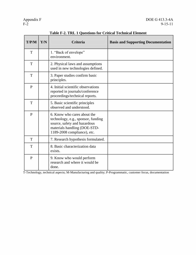
Appendix F DOE G 413.3-4A
F-2 9-15-11
Table F-2. TRL 1 Questions for Critical Technical Element
T/P/M Y/N Criteria Basis and Supporting Documentation
T 1. “Back of envelope”
environment.
T 2. Physical laws and assumptions
used in new technologies defined.
T 3. Paper studies confirm basic
principles.
P 4. Initial scientific observations
reported in journals/conference
proceedings/technical reports.
T 5. Basic scientific principles
observed and understood.
P 6. Know who cares about the
technology, e.g., sponsor, funding
source, safety and hazardous
materials handling (DOE-STD-
1189-2008 compliance), etc.
T 7. Research hypothesis formulated.
T 8. Basic characterization data
exists.
P 9. Know who would perform
research and where it would be
done.
T-Technology, technical aspects; M-Manufacturing and quality; P-Programmatic, customer focus, documentation
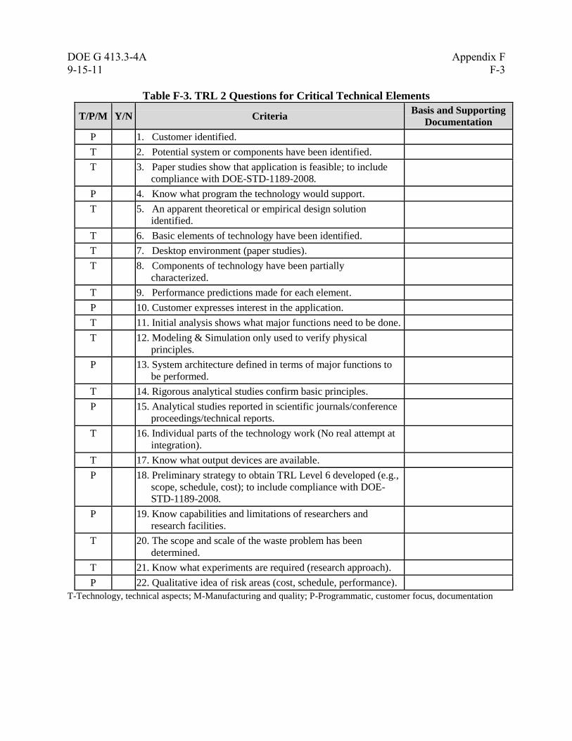
DOE G 413.3-4A Appendix F
9-15-11 F-3
Table F-3. TRL 2 Questions for Critical Technical Elements
T/P/M Y/N Criteria Basis and Supporting
Documentation
P 1. Customer identified.
T 2. Potential system or components have been identified.
T 3. Paper studies show that application is feasible; to include
compliance with DOE-STD-1189-2008.
P 4. Know what program the technology would support.
T 5. An apparent theoretical or empirical design solution
identified.
T 6. Basic elements of technology have been identified.
T 7. Desktop environment (paper studies).
T 8. Components of technology have been partially
characterized.
T 9. Performance predictions made for each element.
P 10. Customer expresses interest in the application.
T 11. Initial analysis shows what major functions need to be done.
T 12. Modeling & Simulation only used to verify physical
principles.
P 13. System architecture defined in terms of major functions to
be performed.
T 14. Rigorous analytical studies confirm basic principles.
P 15. Analytical studies reported in scientific journals/conference
proceedings/technical reports.
T 16. Individual parts of the technology work (No real attempt at
integration).
T 17. Know what output devices are available.
P 18. Preliminary strategy to obtain TRL Level 6 developed (e.g.,
scope, schedule, cost); to include compliance with DOE-
STD-1189-2008.
P 19. Know capabilities and limitations of researchers and
research facilities.
T 20. The scope and scale of the waste problem has been
determined.
T 21. Know what experiments are required (research approach).
P 22. Qualitative idea of risk areas (cost, schedule, performance).
T-Technology, technical aspects; M-Manufacturing and quality; P-Programmatic, customer focus, documentation
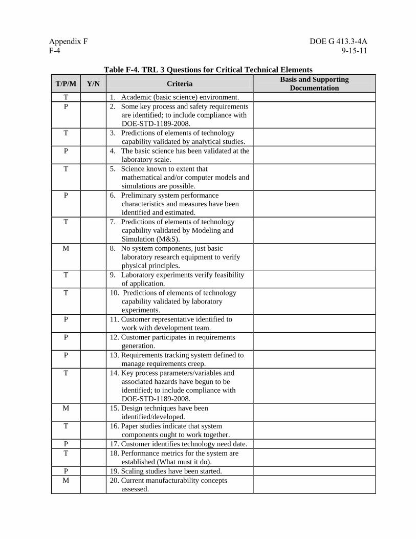
Appendix F DOE G 413.3-4A
F-4 9-15-11
Table F-4. TRL 3 Questions for Critical Technical Elements
T/P/M Y/N Criteria Basis and Supporting
Documentation
T 1. Academic (basic science) environment.
P 2. Some key process and safety requirements
are identified; to include compliance with
DOE-STD-1189-2008.
T 3. Predictions of elements of technology
capability validated by analytical studies.
P 4. The basic science has been validated at the
laboratory scale.
T 5. Science known to extent that
mathematical and/or computer models and
simulations are possible.
P 6. Preliminary system performance
characteristics and measures have been
identified and estimated.
T 7. Predictions of elements of technology
capability validated by Modeling and
Simulation (M&S).
M 8. No system components, just basic
laboratory research equipment to verify
physical principles.
T 9. Laboratory experiments verify feasibility
of application.
T 10. Predictions of elements of technology
capability validated by laboratory
experiments.
P 11. Customer representative identified to
work with development team.
P 12. Customer participates in requirements
generation.
P 13. Requirements tracking system defined to
manage requirements creep.
T 14. Key process parameters/variables and
associated hazards have begun to be
identified; to include compliance with
DOE-STD-1189-2008.
M 15. Design techniques have been
identified/developed.
T 16. Paper studies indicate that system
components ought to work together.
P 17. Customer identifies technology need date.
T 18. Performance metrics for the system are
established (What must it do).
P 19. Scaling studies have been started.
M 20. Current manufacturability concepts
assessed.

DOE G 413.3-4A Appendix F
9-15-11 F-5
T/P/M Y/N Criteria Basis and Supporting
Documentation
M 21. Sources of key components for laboratory
testing identified.
T 22. Scientific feasibility fully demonstrated.
T 23. Analysis of present state of the art shows
that technology fills a need.
P 24. Risk areas identified in general terms.
P 25. Risk mitigation strategies identified.
P 26. Rudimentary best value analysis
performed for operations.
T 27. Key physical and chemical properties
have been characterized for a number of
waste samples.
T 28. A simulant has been developed that
approximates key waste properties.
T 29. Laboratory scale tests on a simulant have
been completed.
T 30. Specific waste(s) and waste site(s) has
(have) been defined.
T 31. The individual system components have
been tested at the laboratory scale.
T-Technology, technical aspects; M-Manufacturing and quality; P-Programmatic, customer focus, documentation

Appendix F DOE G 413.3-4A
F-6 9-15-11
Table F-5. TRL 4 Questions for Critical Technical Elements
T/P/M Y/N Criteria
Basis and Supporting
Documentation
T 1. Key process variables/parameters been fully
identified and preliminary hazard evaluations have
been completed and documented to include
compliance with DOE-STD-1189-2008.
M 2. Laboratory components tested are surrogates for
system components.
T 3. Individual components tested in laboratory/ or by
supplier.
T 4. Subsystems composed of multiple components
tested at lab scale using simulants.
T 5. Modeling & Simulation used to simulate some
components and interfaces between components.
P 6. Overall system requirements for end user's
application are known.
T 7. Overall system requirements for end user's
application are documented.
P 8. System performance metrics measuring
requirements have been established.
P 9. Laboratory testing requirements derived from
system requirements are established.
M 10. Available components assembled into laboratory
scale system.
T 11. Laboratory experiments with available components
show that they work together.
T 12. Analysis completed to establish component
compatibility (Do components work together).
P 13. Science and Technology Demonstration exit criteria
established (S&T targets understood, documented,
and agreed to by sponsor).
T 14. Technology demonstrates basic functionality in
simulated environment; to include test and
validation of safety functions.
M 15. Scalable technology prototypes have been produced
(Can components be made bigger than lab scale).
P 16. The conceptual design has been documented
(system description, process flow diagrams, general

DOE G 413.3-4A Appendix F
9-15-11 F-7
T/P/M Y/N Criteria
Basis and Supporting
Documentation
arrangement drawings, and material balance).
M 17. Equipment scale-up relationships are
understood/accounted for in technology
development program.
T 18. Controlled laboratory environment used in testing.
P 19. Initial cost drivers identified.
M 20. Integration studies have been started.
P 21. Formal risk management program initiated.
M 22. Key manufacturing processes for equipment
systems identified.
P 23. Scaling documents and designs of technology have
been completed.
M 24. Key manufacturing processes assessed in
laboratory.
P/T 25. Functional process description developed.
(Systems/subsystems identified).
T 26. Low fidelity technology “system” integration and
engineering completed in a lab environment.
M 27. Mitigation strategies identified to address
manufacturability/ producibility shortfalls.
T 28. Key physical and chemical properties have been
characterized for a range of wastes.
T 29. A limited number of simulants have been
developed that approximate the range of waste
properties.
T 30. Laboratory-scale tests on a limited range of
simulants and real waste have been completed.
T 31. Process/parameter limits and safety control
strategies are being explored.
T 32. Test plan documents for prototypical lab- scale tests
completed.
P 33. Technology availability dates established.
T-Technology, technical aspects; M-Manufacturing and quality; P-Programmatic, customer focus, documentation

Appendix F DOE G 413.3-4A
F-8 9-15-11
Table F-6. TRL 5 Questions for Critical Technical Elements
T/P/M Y/N Criteria Basis and Supporting
Documentation
T 1. The relationships between major
system and sub-system parameters are
understood on a laboratory scale.
T 2. Plant size components available for
testing.
T 3. System interface requirements known
(How would system be integrated into
the plant?).
P 4. Preliminary design engineering
begins.
T 5. Requirements for technology
verification established; to include
testing and validation of safety
functions.
T 6. Interfaces between components/
subsystems in testing are realistic
(bench top with realistic interfaces).
M 7. Prototypes of equipment system
components have been created (know
how to make equipment).
M 8. Tooling and machines demonstrated in
lab for new manufacturing processes
to make component.
T 9. High fidelity lab integration of system
completed, ready for test in relevant
environments; to include testing and
validation of safety functions.
M 10. Manufacturing techniques have been
defined to the point where largest
problems defined.
T 11. Lab-scale, similar system tested with
range of simulants.
T 12. Fidelity of system mock-up improves
from laboratory to bench-scale testing.
M 13. Availability and reliability (RAMI)
target levels identified.
M 14. Some special purpose components
combined with available laboratory
components for testing.
P 15. Three dimensional drawings and
P&IDs for the prototypical
engineering-scale test facility have
been prepared.
T 16. Laboratory environment for testing
modified to approximate operational
environment; to include testing and

DOE G 413.3-4A Appendix F
9-15-11 F-9
T/P/M Y/N Criteria Basis and Supporting
Documentation
validation of safety functions.
T 17. Component integration issues and
requirements identified.
P 18. Detailed design drawings have been
completed to support specification of
engineering-scale testing system.
T 19. Requirements definition with
performance thresholds and objectives
established for final plant design.
P 20. Preliminary technology feasibility
engineering report completed; to
include compliance with DOE-STD-
1189-2008.
T 21. Integration of modules/functions
demonstrated in a laboratory/bench-
scale environment.
T 22. Formal control of all components to
be used in final prototypical test
system.
P 23. Configuration management plan in
place.
T 24. The range of all relevant physical and
chemical properties has been
determined (to the extent possible).
T 25. Simulants have been developed that
cover the full range of waste
properties.
T 26. Testing has verified that the
properties/performance of the
simulants match the
properties/performance of the actual
wastes.
T 27. Laboratory-scale tests on the full
range of simulants using a prototypical
system have been completed.
T 28. Laboratory-scale tests on a limited
range of real wastes using a
prototypical system have been
completed.
T 29. Test results for simulants and real
waste are consistent.
T 30. Laboratory to engineering scale scale-
up issues are understood and resolved;
to include testing and validation of
safety functions.

Appendix F DOE G 413.3-4A
F-10 9-15-11
T/P/M Y/N Criteria Basis and Supporting
Documentation
T 31. Limits for all process
variables/parameters and safety
controls are being refined.
P 32. Test plan for prototypical lab-scale
tests executed – results validate
design; to include testing and
validation of safety functions.
P 33. Test plan documents for prototypical
engineering-scale tests completed.
P 34. Finalization of hazardous material
forms and inventories, completion of
process hazard analysis, and
identification of system/components
level safety controls at the appropriate
preliminary design phase.
P 35. Risk management plan documented;
to include compliance with DOE-
STD-1189-2008.
T-Technology, technical aspects; M-Manufacturing and quality; P-Programmatic, customer focus, documentation
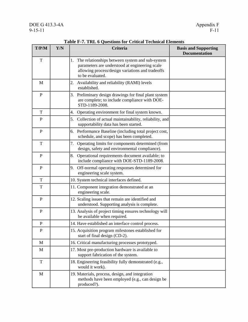
DOE G 413.3-4A Appendix F
9-15-11 F-11
Table F-7. TRL 6 Questions for Critical Technical Elements
T/P/M Y/N Criteria Basis and Supporting
Documentation
T 1. The relationships between system and sub-system
parameters are understood at engineering scale
allowing process/design variations and tradeoffs
to be evaluated.
M 2. Availability and reliability (RAMI) levels
established.
P 3. Preliminary design drawings for final plant system
are complete; to include compliance with DOE-
STD-1189-2008.
T 4. Operating environment for final system known.
P 5. Collection of actual maintainability, reliability, and
supportability data has been started.
P 6. Performance Baseline (including total project cost,
schedule, and scope) has been completed.
T 7. Operating limits for components determined (from
design, safety and environmental compliance).
P 8. Operational requirements document available; to
include compliance with DOE-STD-1189-2008.
P 9. Off-normal operating responses determined for
engineering scale system.
T 10. System technical interfaces defined.
T 11. Component integration demonstrated at an
engineering scale.
P 12. Scaling issues that remain are identified and
understood. Supporting analysis is complete.
P 13. Analysis of project timing ensures technology will
be available when required.
P 14. Have established an interface control process.
P 15. Acquisition program milestones established for
start of final design (CD-2).
M 16. Critical manufacturing processes prototyped.
M 17. Most pre-production hardware is available to
support fabrication of the system.
T 18. Engineering feasibility fully demonstrated (e.g.,
would it work).
M 19. Materials, process, design, and integration
methods have been employed (e.g., can design be
produced?).
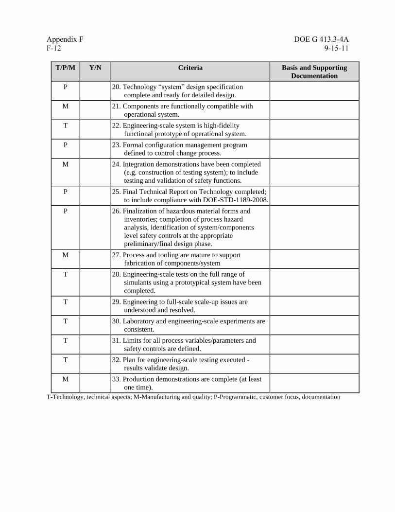
Appendix F DOE G 413.3-4A
F-12 9-15-11
T/P/M Y/N Criteria Basis and Supporting
Documentation
P 20. Technology “system” design specification
complete and ready for detailed design.
M 21. Components are functionally compatible with
operational system.
T 22. Engineering-scale system is high-fidelity
functional prototype of operational system.
P 23. Formal configuration management program
defined to control change process.
M 24. Integration demonstrations have been completed
(e.g. construction of testing system); to include
testing and validation of safety functions.
P 25. Final Technical Report on Technology completed;
to include compliance with DOE-STD-1189-2008.
P 26. Finalization of hazardous material forms and
inventories; completion of process hazard
analysis, identification of system/components
level safety controls at the appropriate
preliminary/final design phase.
M 27. Process and tooling are mature to support
fabrication of components/system
T 28. Engineering-scale tests on the full range of
simulants using a prototypical system have been
completed.
T 29. Engineering to full-scale scale-up issues are
understood and resolved.
T 30. Laboratory and engineering-scale experiments are
consistent.
T 31. Limits for all process variables/parameters and
safety controls are defined.
T 32. Plan for engineering-scale testing executed -
results validate design.
M 33. Production demonstrations are complete (at least
one time).
T-Technology, technical aspects; M-Manufacturing and quality; P-Programmatic, customer focus, documentation
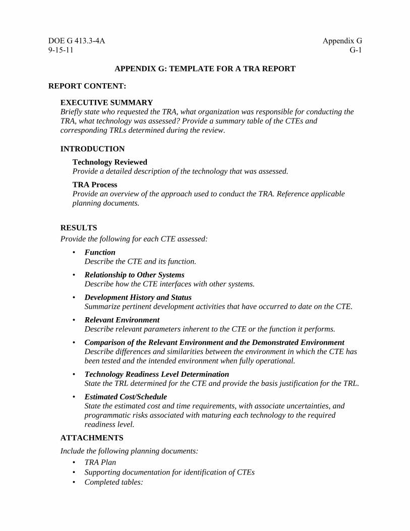
DOE G 413.3-4A Appendix G
9-15-11 G-1
APPENDIX G: TEMPLATE FOR A TRA REPORT
REPORT CONTENT:
EXECUTIVE SUMMARY Briefly state who requested the TRA, what organization was responsible for conducting the
TRA, what technology was assessed? Provide a summary table of the CTEs and
corresponding TRLs determined during the review.
INTRODUCTION
Technology Reviewed Provide a detailed description of the technology that was assessed.
TRA Process Provide an overview of the approach used to conduct the TRA. Reference applicable
planning documents.
RESULTS
Provide the following for each CTE assessed:
• Function Describe the CTE and its function.
• Relationship to Other Systems Describe how the CTE interfaces with other systems.
• Development History and Status Summarize pertinent development activities that have occurred to date on the CTE.
• Relevant Environment Describe relevant parameters inherent to the CTE or the function it performs.
• Comparison of the Relevant Environment and the Demonstrated Environment Describe differences and similarities between the environment in which the CTE has
been tested and the intended environment when fully operational.
• Technology Readiness Level Determination State the TRL determined for the CTE and provide the basis justification for the TRL.
• Estimated Cost/Schedule State the estimated cost and time requirements, with associate uncertainties, and
programmatic risks associated with maturing each technology to the required
readiness level.
ATTACHMENTS
Include the following planning documents:
• TRA Plan
• Supporting documentation for identification of CTEs
• Completed tables:
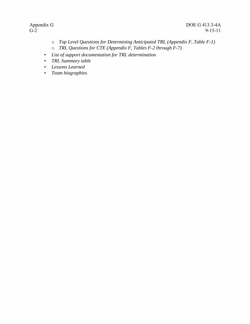
Appendix G DOE G 413.3-4A
G-2 9-15-11
o Top Level Questions for Determining Anticipated TRL (Appendix F, Table F-1)
o TRL Questions for CTE (Appendix F, Tables F-2 through F-7)
• List of support documentation for TRL determination
• TRL Summary table
• Lessons Learned
• Team biographies
DOE G 413.3-4A Appendix H
9-15-11 H-1
Appendix H: Template Guide for a Technology Maturation Plan
(Note: The TMP is a high level summary document. It is not a collection of detailed test plans.)
TABLE OF CONTENTS
LIST OF TABLES
LIST OF FIGURES
ABBREVIATIONS AND ACRONYMS
1.0 INTRODUCTION
• Purpose of the Project
Provide a brief summary of the project’s mission, status, technology(s) being
deployed, etc.
• Purpose of the TMP
Describe the objectives and content of this TMP and relate it to the status of the
project and any upcoming CDs.
2.0 TECHNOLOGY ASSESSMENTS OF THE PROJECT
• Summary of Previous TIPRs
Summarize any previous TIPRs or other technical assessments that may have
contributed to the need for a TRA and this TMP.
• Summary of Previous TRA(s)
Describe the results of previous TRAs with particular emphasis on the latest TRA that
is driving this TMP. Include the definition of TRLs as used in the TRA. Discuss the
CTEs that were determined for the project.
• Technology Heritage
Summarize the previous technology development activities that brought the
technology to its current state of readiness. Include discussions of any full-scale plant
deployments of the technology in similar applications.
• Current Project Activities and Technology Maturation
Describe ongoing technology development activities (if any) that were initiated prior
to this TMP. Completion of these activities should define the starting point for this
TMP.
• Management of Technology Maturity
Indicate the DOE and contractor organizations that will be responsible for managing
the activities described in this TMP. Include a brief discussion of key roles and
responsibilities.
3.0 TECHNOLOGY MATURATION PLAN
• Development of Technology Maturation Requirements
Describe the approach used in defining the required technology development
activities that will be conducted as described in this TMP. These could include
Appendix H DOE G 413.3-4A
H-2 9-15-11
evaluating incomplete criteria in the TRL Calculator, risk assessments, and value
engineering.
• Life-Cycle Benefit
Briefly discuss life-cycle benefits to the project that will result from successful
completion of the TMP technology development activities.
• Specific TMPs for each CTE will be described following the format below for each
CTE that was defined in the latest TRA.
− CTE A
o Key Technology Addressed (Describe the function that the CTE carries out in
the project.)
o Objective (Succinctly state the objective of the CTE)
o Current State of Art (Describe in one paragraph the current status of the CTE
including the specific TRL assigned in the latest TRA.)
o Technology Development Approach (In paragraph form, describe how the
needed technology development work to reach TRL 6 will be performed. This
could include the performing organization, location, simulant versus actual
waste, etc.)
o Scope (Provide a list of the key steps to be taken in performing the work.
Include a table that gives milestones, performance targets, TRL achieved at
milestones, and a rough order of magnitude cost of development.)
− CTE B
o Key Technology Addressed
o Objective
o Current State of Art
o Technology Development Approach
o Scope
− CTE C (etc., as needed)
4.0 TECHNOLOGY MATURITY SCHEDULE
Provide and briefly discuss a high-level schedule of the major technology development
activities for each CTE. Any major decision points such as proceeding with versus
abandoning the current technology, selection of a back-up technology, etc. should be
included. Detailed schedules should be given in test plans or used for status meetings
during implementation.
DOE G 413.3-4A Appendix H
9-15-11 H-3 (and H-4)
5.0 SUMMARY TECHNOLOGY MATURITY BUDGET
Present the rough order of magnitude costs to reach TRL 6 for each major technology
development activity for all CTEs in the project. Include the total technology maturation
costs.
6.0 REFERENCES
Appendix A. Crosswalk of CTEs identified in previous independent reviews and
assessments (if applicable)
Appendix B. TRL Calculator as Modified by the DOE Program Office (if
applicable)
Table 1. TRLs Used in this Assessment (taken from DoD)
Table 2, etc. Table(s) for each CTE, listing of test activities, planned completion
date, performance targets, resulting TRL level as each increment of
testing is completed, and rough order of magnitude costs.
Table X. Technology Maturity Budget for Project
Figure 1. Process Flow Diagram (for technology being assessed)
Figure 2. Technology Maturity Schedule
Figure 3. Project Execution Strategy Diagram
Related Documents