Techno Economic Feasibility Report - Final August 2016 TECHNO ECONOMIC FEASIBILITY REPORT FOR DEVELOPMENT OF PORT AT BELEKERI

Welcome message from author
This document is posted to help you gain knowledge. Please leave a comment to let me know what you think about it! Share it to your friends and learn new things together.
Transcript
Techno Economic Feasibility Report - Final August 2016
TECHNO ECONOMIC FEASIBILITY REPORT FOR DEVELOPMENT OF
PORT AT BELEKERI
Techno-Economic Feasibility Report forDevelopment of Port at Belekeri
Prepared for
Ministry of Shipping / Indian Ports AssociationTransport Bhawan,Sansad Marg,New Delhi,110001www.shipping.nic.in
1st Floor, South Tower, NBCC PlaceB. P Marg, Lodi RoadNew Delhi - 110 003www.ipa.nic.in
Prepared by
AECOM India Private Limited,9th Floor, Infinity Tower C, DLF Cyber City,DLF Phase II, Gurgaon, Haryana,India, Pin 122002, IndiaTelephone: +91 124 4830100,Fax: +91 124 4830108www.aecom.com
August 2016
© AECOM India Private Limited 2016
This document has been prepared by AECOM India Private Limited for the sole use of our client (the “Client”) and in accordancewith generally accepted consultancy principles, the budget for fees and the terms of reference agreed between AECOM IndiaPrivate Limited and the Client. Any information provided by third parties and referred to herein has not been checked or verifiedby AECOM India Private Limited, unless otherwise expressly stated in the document. No third party may rely upon this documentwithout the prior and express written agreement of AECOM India Private Limited.
All rights reserved. No section or element of this document may be removed from this document, reproduced, electronicallystored or transmitted in any form without the written permission of AECOM India Private Limited.
Techno-Economic Feasibility Report
Quality Information
Client: Ministry of Shipping / Indian Ports Association Contract No. (if any): NA
Project Title: Development of Port at Belekeri Project No.: DELD15005
Document No: DELD15005-REP-10-0000-CP-1005
SharePoint Ref:Controlled Copy No:
Document Title: Techno-Economic Feasibility Report for Development of Port at Belekeri
Covering Letter/ Transmittal Ref. No: Date of Issue: 01 August 2016
Revision, Review and Approval Records
B.Development of Port at Belekeri- Final
RP29-07-2016
ASM30-07-2016
Sanjeev Gupta01-08-2016
A.Development of Port at Belekeri- Draft
RP16-06-2016
ASM18-06-2016
Sanjeev Gupta19-06-2016
Revision DescriptionPrepared by/
dateReviewed by/ date
Approved by/date
Document Revision Register
Issueno.
Date of issue Section Revision DetailsRevision By Name
& Position
1. 01.08.2016 Comments on Draft Report RPSenior Consultant
Development of Port at Belekeri iTechno-Economic Feasibility Report
TableofContentsEXECUTIVE SUMMARY ...................................................................................................................................VIII
INTRODUCTION .................................................................................................................................. 1-11.0
BACKGROUND ..................................................................................................................................... 1-11.1SCOPE OF WORK ................................................................................................................................. 1-21.2NEED FOR THE NEW PORT AT BELEKERI ..................................................................................................... 1-21.3PRESENT SUBMISSION ........................................................................................................................... 1-31.4
SITE CONDITIONS ............................................................................................................................... 2-12.0
ALTERNATIVE SITES ALONG THE COASTLINE OF KARNATAKA ............................................................................ 2-12.1PORT LOCATION AT BELEKERI .................................................................................................................. 2-32.2METEOROLOGICAL DATA ....................................................................................................................... 2-52.3
Climate .................................................................................................................................... 2-52.3.1Visibility ................................................................................................................................... 2-62.3.2Wind ....................................................................................................................................... 2-62.3.3Cyclones .................................................................................................................................. 2-72.3.4
SITE SEISMICITY ................................................................................................................................... 2-72.4OCEANOGRAPHIC INFORMATION ............................................................................................................. 2-82.5
Tide Levels ............................................................................................................................... 2-82.5.1Wave Conditions ...................................................................................................................... 2-82.5.2Currents................................................................................................................................... 2-92.5.3Bathymetry.............................................................................................................................. 2-92.5.4
LITTORAL DRIFT ................................................................................................................................. 2-102.6CONNECTIVITY .................................................................................................................................. 2-102.7
Rail Connectivity .................................................................................................................... 2-102.7.1Road Connectivity .................................................................................................................. 2-112.7.2
WATER SUPPLY ................................................................................................................................. 2-132.8POWER SUPPLY ................................................................................................................................. 2-132.9QUARRY SITES................................................................................................................................... 2-142.10
TRAFFIC PROJECTIONS ........................................................................................................................ 3-13.0
GENERAL ........................................................................................................................................... 3-13.1MAJOR COMMODITIES AND THEIR PROJECTIONS .......................................................................................... 3-13.2
Thermal Coal ........................................................................................................................... 3-13.2.1Iron Ore ................................................................................................................................... 3-13.2.2Coking Coal.............................................................................................................................. 3-23.2.3
POTENTIAL TRADE AND DEVELOPMENT OPPORTUNITIES FOR BELEKERI PORT ...................................................... 3-33.3General ................................................................................................................................... 3-33.3.1Hinterland Development .......................................................................................................... 3-33.3.2Major Exports .......................................................................................................................... 3-43.3.3
DESIGN SHIP SIZES .............................................................................................................................. 4-14.0
GENERAL ........................................................................................................................................... 4-14.1DRY BULK SHIPS .................................................................................................................................. 4-14.2CONTAINER SHIPS ................................................................................................................................ 4-24.3
Development of Port at Belekeri iiTechno-Economic Feasibility Report
DESIGN SHIP SIZES ............................................................................................................................... 4-24.4
PORT FACILITY REQUIREMENTS .......................................................................................................... 5-15.0
GENERAL ........................................................................................................................................... 5-15.1BERTH REQUIREMENTS.......................................................................................................................... 5-15.2
General ................................................................................................................................... 5-15.2.1Cargo Handling Systems .......................................................................................................... 5-25.2.2Operational Time ..................................................................................................................... 5-25.2.3Time Required for Peripheral Activities ..................................................................................... 5-25.2.4Allowable Levels of Berth Occupancy........................................................................................ 5-25.2.5Berths Requirements for the Master Plan ................................................................................. 5-35.2.6Port Crafts Berth ...................................................................................................................... 5-35.2.7Length of the Berths ................................................................................................................ 5-35.2.8
STORAGE REQUIREMENTS ...................................................................................................................... 5-45.3BUILDINGS ......................................................................................................................................... 5-45.4
Terminal Administration Building ............................................................................................. 5-45.4.1Signal Station .......................................................................................................................... 5-45.4.2Customs Office......................................................................................................................... 5-45.4.3Gate Complex .......................................................................................................................... 5-55.4.4Substations .............................................................................................................................. 5-55.4.5Worker’s Amenities Building .................................................................................................... 5-55.4.6Maintenance Workshops ......................................................................................................... 5-55.4.7Other Miscellaneous Buildings ................................................................................................. 5-55.4.8
RECEIPT AND EVACUATION OF CARGO ....................................................................................................... 5-55.5General ................................................................................................................................... 5-55.5.1Port Access Road ..................................................................................................................... 5-65.5.2Rail Connectivity ...................................................................................................................... 5-65.5.3
WATER REQUIREMENTS ........................................................................................................................ 5-65.6POWER REQUIREMENTS ........................................................................................................................ 5-65.7LAND AREA REQUIREMENT..................................................................................................................... 5-75.8
PREPARATION OF PORT LAYOUT ........................................................................................................ 6-16.0
LAYOUT DEVELOPMENT ......................................................................................................................... 6-16.1BRIEF DESCRIPTIONS OF KEY CONSIDERATIONS ............................................................................................ 6-16.2
Potential Traffic ....................................................................................................................... 6-16.2.1Techno-Economic Feasibility .................................................................................................... 6-26.2.2Land Availability ...................................................................................................................... 6-46.2.3Environmental Issues Related to Development ......................................................................... 6-46.2.4
PLANNING CRITERIA ............................................................................................................................. 6-56.3Limiting Wave Conditions for Port Operations .......................................................................... 6-56.3.1Breakwaters ............................................................................................................................ 6-66.3.2Berths ...................................................................................................................................... 6-66.3.3Navigational Channel Dimensions ............................................................................................ 6-76.3.4Elevations of Backup Area and Berths .................................................................................... 6-116.3.5
ALTERNATIVE MARINE LAYOUTS ............................................................................................................ 6-116.4EVALUATION OF THE ALTERNATIVE PORT LAYOUTS ..................................................................................... 6-116.5
Cost Aspects .......................................................................................................................... 6-116.5.1
Development of Port at Belekeri iiiTechno-Economic Feasibility Report
Fast Track Implementation of Phase 1 .................................................................................... 6-126.5.2Available Land for Phased Development ................................................................................. 6-126.5.3Expansion Potential ............................................................................................................... 6-126.5.4
MULTI CRITERIA ANALYSIS OF ALTERNATIVE PORT LAYOUTS ......................................................................... 6-136.6RECOMMENDED MASTER PLAN LAYOUT .................................................................................................. 6-146.7RECOMMENDED PORT LAYOUT BEYOND MASTER PLAN HORIZON .................................................................. 6-146.8PHASING OF THE PORT DEVELOPMENT .................................................................................................... 6-156.9
ENGINEERING DETAILS ....................................................................................................................... 7-17.0
MATHEMATICAL MODEL STUDIES ON MARINE LAYOUT ................................................................................. 7-17.1Model Results .......................................................................................................................... 7-37.1.1
ONSHORE FACILITIES............................................................................................................................. 7-57.2BREAKWATERS .................................................................................................................................... 7-67.3
Basic Data for Breakwaters Design........................................................................................... 7-67.3.1Breakwater Cross Sections ....................................................................................................... 7-77.3.2Geotechnical Assessment of Breakwaters ................................................................................. 7-87.3.3Rock Quarrying and Transportation ......................................................................................... 7-87.3.4
BERTHING FACILITIES ............................................................................................................................ 7-87.4Location and Orientation ......................................................................................................... 7-87.4.1Deck Elevation ......................................................................................................................... 7-87.4.2Design Criteria ......................................................................................................................... 7-97.4.3Proposed Structural Arrangement of Berths ........................................................................... 7-107.4.4
DREDGING AND DISPOSAL .................................................................................................................... 7-127.5Capital Dredging .................................................................................................................... 7-127.5.1Maintenance Dredging .......................................................................................................... 7-127.5.2
RECLAMATION .................................................................................................................................. 7-127.6Areas to be Reclaimed ........................................................................................................... 7-127.6.1
MATERIAL HANDLING SYSTEM .............................................................................................................. 7-127.7Bulk Import System ................................................................................................................ 7-127.7.1Break Bulk Handling System ................................................................................................... 7-147.7.2
ROAD CONNECTIVITY .......................................................................................................................... 7-197.8External Road Connectivity .................................................................................................... 7-197.8.1Internal Roads ....................................................................................................................... 7-197.8.2
RAIL CONNECTIVITY ............................................................................................................................ 7-207.9External Rail Connectivity ....................................................................................................... 7-207.9.1Internal Rail Links .................................................................................................................. 7-217.9.2
PORT INFRASTRUCTURE ....................................................................................................................... 7-217.10Electrical Distribution System ................................................................................................. 7-217.10.1Communication System.......................................................................................................... 7-237.10.2Computerized Information System ......................................................................................... 7-247.10.3Water Supply ......................................................................................................................... 7-257.10.4Drainage and Sewerage System ............................................................................................. 7-267.10.5Floating Crafts for Marine Operations .................................................................................... 7-267.10.6Navigational Aids................................................................................................................... 7-277.10.7Security System Complying with ISPS ...................................................................................... 7-287.10.8Firefighting System ................................................................................................................ 7-297.10.9
Pollution Control ................................................................................................................ 7-307.10.10
Development of Port at Belekeri ivTechno-Economic Feasibility Report
ENVIRONMENTAL SETTINGS AND IMPACT EVALUATION .................................................................... 8-18.0
INTRODUCTION ................................................................................................................................... 8-18.1GENERAL ........................................................................................................................................... 8-18.2SITE SETTING ...................................................................................................................................... 8-18.3ENVIRONMENTAL POLICIES AND LEGISLATION ............................................................................................. 8-38.4ANTICIPATED ENVIRONMENTAL IMPACTS AND MITIGATION MEASURES ............................................................. 8-58.5IMPACTS DURING CONSTRUCTION PHASE .................................................................................................. 8-68.6
Impacts on Land and Soil ......................................................................................................... 8-68.6.1Impacts on Water Quality ........................................................................................................ 8-78.6.2Impact of Air Quality ................................................................................................................ 8-88.6.3Impacts on Noise Quality ......................................................................................................... 8-98.6.4Impacts on Ecology ................................................................................................................ 8-108.6.5Impact on Social Conditions ................................................................................................... 8-108.6.6
IMPACTS DURING OPERATION PHASE...................................................................................................... 8-118.7Impact on Water Quality ........................................................................................................ 8-118.7.1Impact on Air Quality ............................................................................................................. 8-118.7.2Impact on Noise Quality ......................................................................................................... 8-128.7.3Impact on Ecology ................................................................................................................. 8-128.7.4Impact on Socio-Economic Conditions .................................................................................... 8-138.7.5
ENVIRONMENTAL MONITORING PLAN ..................................................................................................... 8-148.8ENVIRONMENTAL MANAGEMENT COST ................................................................................................... 8-148.9
COST ESTIMATES AND IMPLEMENTATION SCHEDULE......................................................................... 9-19.0
CAPITAL COST ESTIMATES ...................................................................................................................... 9-19.1General ................................................................................................................................... 9-19.1.1Capital Cost Estimates for Phased Development ....................................................................... 9-19.1.2
OPERATION AND MAINTENANCE COSTS ..................................................................................................... 9-39.2General ................................................................................................................................... 9-39.2.1Repair and Maintenance Costs ................................................................................................. 9-39.2.2Manpower Costs ...................................................................................................................... 9-39.2.3Operation Costs ....................................................................................................................... 9-39.2.4Annual Incremental Operation and Maintenance Costs ............................................................ 9-39.2.5
IMPLEMENTATION SCHEDULE FOR PHASE 1 PORT DEVELOPMENT..................................................................... 9-49.3General ................................................................................................................................... 9-49.3.1Construction of Breakwater ..................................................................................................... 9-49.3.2Dredging and Reclamation ....................................................................................................... 9-59.3.3Berths ...................................................................................................................................... 9-59.3.4Equipment and Onshore Development ..................................................................................... 9-59.3.5Implementation Schedule......................................................................................................... 9-59.3.6
FINANCIAL ANALYSIS FOR ALTERNATIVE MEANS OF PROJECT DEVELOPMENT ................................. 10-110.0
ASSUMPTIONS FOR FINANCIAL ASSESSMENT ............................................................................................. 10-110.1OPTION 1 – BY PROJECT PROPONENTS ................................................................................................... 10-110.2OPTION 2 – FULL FLEDGED CONCESSION TO PRIVATE OPERATOR ................................................................... 10-110.3OPTION 3 – LANDLORD MODEL ............................................................................................................ 10-210.4
WAY FORWARD ................................................................................................................................ 11-111.0
Development of Port at Belekeri vTechno-Economic Feasibility Report
List of Figures
Figure 1.1 Aim of Sagarmala Development .............................................................................. 1-1Figure 1.2 Governing Principles of Our Approach ..................................................................... 1-2Figure 2.1 Alternative Sites for Location of Port ........................................................................ 2-1Figure 2.2 Evaluation of Sites (Belambar, Tadadi and Vannali) ................................................ 2-2Figure 2.3 Evaluation of Sites (Haldipur, Hadin and Hangarkatta) ............................................. 2-2Figure 2.4 Location of Belekeri ................................................................................................. 2-3Figure 2.5 Location of the Proposed Site .................................................................................. 2-4Figure 2.6 Picture Showing Identified Waterfront for Proposed Port .......................................... 2-5Figure 2.7 Annual Wind Rose Diagram .................................................................................... 2-6Figure 2.8 Seismic Zoning Map of India as per IS-1893 Part 1-2002......................................... 2-7Figure 2.9 Resultant Annual Wave Rose Doagram for Deep and Nearshore Condition ............. 2-8Figure 2.10 Range of Monthly Hs (m) & Tp (s) ........................................................................... 2-9Figure 2.11 Hydrographic Chart of Proposed Port Site [Source: NHO Chart 293] ....................... 2-9Figure 2.12 Belekeri Port w.r.t. Railway and Highway ............................................................... 2-10Figure 2.13 Existing Road Connecting to Proposed Site ........................................................... 2-11Figure 2.14 Road Connecting to Proposed Port Site ................................................................ 2-12Figure 2.15 Honnalli Water Supply Scheme ............................................................................. 2-13Figure 2.16 Location of Balegulli Substation ............................................................................. 2-13Figure 6.1 Current Land Pattern along Proposed Site............................................................... 6-4Figure 7.1 Bathymetry Used for the BW ................................................................................... 7-1Figure 7.2 Sponge Layers (in Green) along the Non-Reflecting Boundaries.............................. 7-2Figure 7.3 Porosity Layers (in Red) along the Port Structures ................................................... 7-2Figure 7.4 Wave Tranquillity Assessment for Waves from NNW Direction ................................ 7-3Figure 7.5 Wave Tranquillity Assessment for Waves from NW Direction ................................... 7-4Figure 7.6 Wave Tranquillity Assessment for Waves from W Direction ..................................... 7-4Figure 7.7 Typical Ship Unloader ........................................................................................... 7-13Figure 7.8 Mobile Harbour Crane with Spreader Arrangement ................................................ 7-15Figure 7.9 Typical E-RTG for Yard Operation ......................................................................... 7-16Figure 7.10 Typical Details of Electric Buss Bar Arrangement for E-RTG.................................. 7-16Figure 7.11 Typical Details of Reefer Stacks ............................................................................ 7-17Figure 7.12 Snapshot of Typical Reach Stacker Handling ........................................................ 7-18Figure 7.13 Typical ITV for Handling Containers ...................................................................... 7-18Figure 7.14 Proposed Alignment of External Road Connectivity ............................................... 7-19Figure 7.15 Alternative Rail Alignment to Port at Belekeri ......................................................... 7-20Figure 8.1 Location of the Proposed Site .................................................................................. 8-2Figure 8.2 Coastal Stability Map of Uttara Kannada District ...................................................... 8-3Figure 11.1 Process for the Greenfield Port Development ........................................................ 11-2
Development of Port at Belekeri viTechno-Economic Feasibility Report
List of Drawings
Drawing No. Drawing Title
DELD15005 - DRG - 10 - 0000 - CP - BLR1001 Alternative Layout 1 Master Plan
DELD15005 - DRG - 10 - 0000 - CP - BLR1002 Alternative Layout 1 Phase 1
DELD15005 - DRG - 10 - 0000 - CP - BLR1003 Alternative Layout 2 Master Plan
DELD15005 - DRG - 10 - 0000 - CP - BLR1004 Alternative Layout 2 Phase 1
DELD15005 - DRG - 10 - 0000 - CP - BLR1005 Recommended Layout Master Plan
DELD15005 - DRG - 10 - 0000 - CP - BLR1006A Potential Expansion Beyond Master Plan Horizon – Alternative 1
DELD15005 - DRG - 10 - 0000 - CP - BLR1006B Potential Expansion Beyond Master Plan Horizon – Alternative 2
DELD15005 - DRG - 10 - 0000 - CP - BLR1007 Recommended Phase 1 Development
DELD15005 - DRG - 10 - 0000 - CP - BLR1008 Typical Cross section of Breakwater
DELD15005 - DRG - 10 - 0000 - CP - BLR1009 Typical Cross section of Bulk Berth
DELD15005 - DRG - 10 - 0000 - CP - BLR1010 Typical Cross section of Container cum Multipurpose Berth
DELD15005 - DRG - 10 - 0000 - CP - BLR1011 Typical Cross Section of Coal Stackyard
DELD15005 - DRG - 10 - 0000 - CP - BLR1012 Layout of Navigational Aids
Development of Port at Belekeri viiTechno-Economic Feasibility Report
List of Tables
Table 2.1 Climatological Table for Karwar Based on Data Between 1961 – 1990 ....................... 2-5Table 2.2 Tide levels.................................................................................................................. 2-8Table 3.1 OD Analysis for Cargoes at Belekeri Port ................................................................... 3-2Table 3.2 Belekeri Traffic Projection........................................................................................... 3-3Table 4.1 Dimensions of the Smallest and Largest Ship ............................................................. 4-2Table 4.2 Parameters of Ship Sizes ........................................................................................... 4-2Table 5.1 Estimated Berths at the Belekeri Port Based on Traffic Forecast ................................ 5-3Table 5.2 Berth Length .............................................................................................................. 5-3Table 5.3 Evacuation Pattern for Various Cargo ......................................................................... 5-6Table 5.4 Minimum Land Area Requirement for Belekeri Port .................................................... 5-7Table 6.1 Limiting Wave Heights for Cargo Handling ................................................................. 6-6Table 6.2 Berth Requirement based on Traffic Forecast ............................................................. 6-6Table 6.3 Assessment of Channel Width .................................................................................... 6-8Table 6.4 Particulars of Navigational Channel for Design Ships ............................................... 6-10Table 6.5 Dredged Levels at Port for the Design Ships ............................................................ 6-10Table 6.6 Cost Differential (Rs. in Crores) of Key Items of Phase 1 Development for .......................
Alternative Layouts ................................................................................................. 6-12Table 6.7 Estimated Rock Quantity and Construction Time of Breakwater ................................ 6-12Table 6.8 Multi-Criteria Analysis of Alternative Layouts ............................................................ 6-13Table 6.9 Phasewise Port Development over Master Plan Horizon .......................................... 6-15Table 7.1 Wave Disturbance Coefficients ................................................................................... 7-5Table 7.2 KD Values for Breakwater ........................................................................................... 7-7Table 7.3 Characteristics of Design Ships .................................................................................. 7-9Table 7.4 Details of Berthing Energy, Fender and Berthing force applied at Berths .................. 7-10Table 7.5 Illumination Level ..................................................................................................... 7-22Table 7.6 Estimated Water Demand for proposed Port at Belekeri ........................................... 7-25Table 7.7 Harbour Craft Requirements..................................................................................... 7-27Table 8.1 Summary of Relevant Environmental Legislations ...................................................... 8-3Table 8.2 Potential Environmental Impacts ................................................................................ 8-5Table 8.3 Environmental Monitoring Plan ................................................................................. 8-14Table 9.1 Block Capital Cost Estimates (Rs. in crores) ............................................................... 9-2Table 9.2 Annual Operation and Maintenance Costs ( Rs. in crores) .......................................... 9-4Table 9.3 Implementation Schedule ........................................................................................... 9-6Table 10.1 Estimated Cost Split ................................................................................................. 10-3
Development of Port at Belekeri viiiTechno-Economic Feasibility Report
EXECUTIVE SUMMARY
Introduction
To make best use of economies of scale, increased global trade and to achieve efficient managementof supply chain, larger sized ships are being built (cape size vessels for moving bulk cargoes) to plyon international routes and as well as Coastal shipping lines. This benefits the cargo owners whohave to bear lower freight costs which eventually lead to low cost of final product for the end user.This trend is seen globally and it is envisaged by Ministry of Shipping that all major ports in India shallhave infrastructure and equipment’s that will be at par with their global peer group.
New Mangalore Port being only deep draft port in the state of Karnataka, shares primary hinterlandwith surroundings of Dakshina Kannada District and secondary hinterland with districts of North &Central Karnataka mainly where the boom of coal requiring industries viz., power plants and steel &Cement Industries exist. Due to its location, rising environmental concerns and lack of properconnectivity to the secondary hinterland, Mormugao port, Krishnapatnam port, Kamarajar port andChennai port have been the natural competitors for the cargoes in this region.
To accommodate the deep draft vessels in the port, New Mangalore Port initially had plans to deepenits channel and inner harbour. However due to involvement of rock dredging and associated blastingwhich involves high cost and interrupts with port activities, there is no plan to deepen the harbour.Therefore, the concept of satellite port for NMP has emerged, which aims at proposal of a Greenfieldport along the Karnataka coast that serve the requirements of secondary hinterland cargo of NMP andalso over coming constraints of deepening harbour. The development of satellite port in the northerncostal Karnataka would be a catalyst in aiding for speeding development of the region by providing theemployment opportunities, industrialisation, cheaper end products to user etc.,
Based on the Origin–Destination studies carried out under Sagarmala assignment, it has beenassessed that there is a good potential of about 37 MTPA of traffic for coastal movement of thermalcoal from eastern region to power plants and steel industries located in the North & CentralKarnataka. These industries can be better served by setting up a port on the coastline of northKarnataka. In addition to diversion of traffic, Belekeri port can also build upon the industrial growth ofKarnataka, which is considered one of India’s most industrialised states, comprising large publicsector industrial undertakings as well as privately-owned industries, e.g., steel, sugar and textiles. Thestate has also evolved as the manufacturing hub for some of the largest public sector industries inIndia.
It is assessed that the proposed port shall cater to the total traffic volumes of 18 MTPA in Phase 1 andincreasing upto 37 MTPA in Master Plan phase (year 2036).
Development of Port at Belekeri ixTechno-Economic Feasibility Report
Port Development Plan
It is proposed that the port facilities shall be developed in the phased manner commensurate withtraffic growth. Considering that the coal would be the key commodity for the port, it is proposed thatport facilities will be able to handle capsize vessels upto 200,000 DWT so as to be in competitiveposition over Krishnapatnam and Mormugao ports. However the initial phase development isproposed to be limited for Panamax vessels to minimise the initial capital investment and thedeepening shall be carried out in for cape size ships in later stages of development.
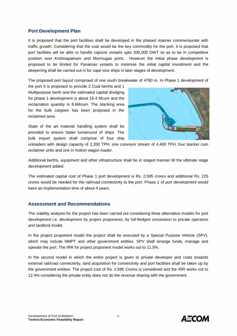
The proposed port layout comprised of one south breakwater of 4780 m. In Phase 1 development ofthe port it is proposed to provide 2 Coal berths and 1Multipurpose berth and the estimated capital dredgingfor phase 1 development is about 16.4 Mcum and thereclamation quantity is 8.6Mcum. The stacking areafor the bulk cargoes has been proposed in thereclaimed area.
State of the art material handling system shall beprovided to ensure faster turnaround of ships. Thebulk import system shall comprise of four shipunloaders with design capacity of 2,200 TPH, one conveyor stream of 4,400 TPH, four stacker cumreclaimer units and one in motion wagon loader.
Additional berths, equipment and other infrastructure shall be in staged manner till the ultimate stagedevelopment added.
The estimated capital cost of Phase 1 port development is Rs. 2,595 crores and additional Rs. 225crores would be needed for the rail/road connectivity to the port. Phase 1 of port development wouldhave an implementation time of about 4 years.
Assessment and Recommendations
The viability analysis for the project has been carried out considering three alternative models for portdevelopment i.e. development by project proponents, by full-fledged concession to private operatorsand landlord model.
In the project proponent model the project shall be executed by a Special Purpose Vehicle (SPV),which may include NMPT and other government entities. SPV shall arrange funds, manage andoperate the port. The IRR for project proponent model works out to 11.5%.
In the second model in which the entire project is given to private developer and costs towardsexternal rail/road connectivity, land acquisition for connectivity and port facilities shall be taken up bythe government entities. The project cost of Rs. 2,595 Crores is considered and the IRR works out to12.4% considering the private entity does not do the revenue sharing with the government.
Development of Port at Belekeri xTechno-Economic Feasibility Report
In the third financial model, SPV shall be responsible for providing the entire basic infrastructure forthe port including the external connectivity and land acquisition to the port. The cargo handlingterminals and associated facilities shall be developed by PPP operator, who shall be responsibleterminal operations & maintenance and also sharing the revenue with the SPV. Limiting the projectIRR to 15% for the PPP operator, he can share about 36% of the revenue with the SPV which isoverall IRR of 9.9% for SPV. Though the estimated IRR for SPV is low, it can be managed if SPV canmanage debt from the international funding agencies. Further if the external rail and road connectivityto the port could be undertaken by NHAI, Railways and IPRCL, the burden on SPV shall reduce.
The thorough analysis of the development of port at Belekeri, it can be concluded that the port has agreat potential and can be developed under Landlord model. However, the entire development of portis dependent on the completion of Hubali – Ankola rail line and the current road blocks on itscompletion need to be removed with active participation from State and Central government. It is alsosuggested that the proposed Hubli Ankola Rail link be extended till Belekeri as a single project to getsynergy and also provide competitive multi-modal transport to the destination.
Development of Port at Belekeri 1-1Techno-Economic Feasibility Report
INTRODUCTION1.0Background1.1
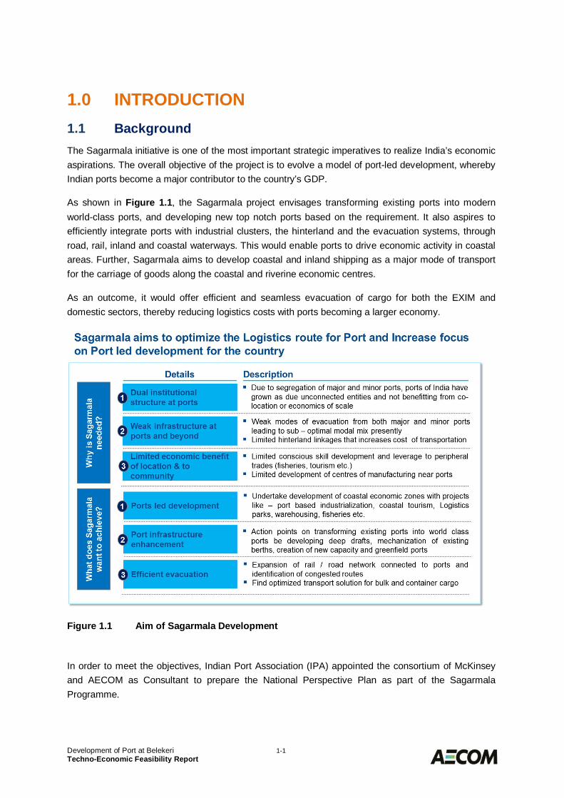
The Sagarmala initiative is one of the most important strategic imperatives to realize India’s economicaspirations. The overall objective of the project is to evolve a model of port-led development, wherebyIndian ports become a major contributor to the country’s GDP.
As shown in Figure 1.1, the Sagarmala project envisages transforming existing ports into modernworld-class ports, and developing new top notch ports based on the requirement. It also aspires toefficiently integrate ports with industrial clusters, the hinterland and the evacuation systems, throughroad, rail, inland and coastal waterways. This would enable ports to drive economic activity in coastalareas. Further, Sagarmala aims to develop coastal and inland shipping as a major mode of transportfor the carriage of goods along the coastal and riverine economic centres.
As an outcome, it would offer efficient and seamless evacuation of cargo for both the EXIM anddomestic sectors, thereby reducing logistics costs with ports becoming a larger economy.
Figure 1.1 Aim of Sagarmala Development
In order to meet the objectives, Indian Port Association (IPA) appointed the consortium of McKinseyand AECOM as Consultant to prepare the National Perspective Plan as part of the SagarmalaProgramme.
Development of Port at Belekeri 1-2Techno-Economic Feasibility Report
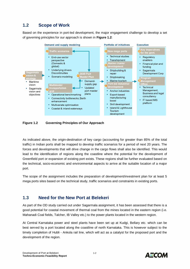
Scope of Work1.2Based on the experience in port-led development, the major engagement challenge to develop a setof governing principles for our approach is shown in Figure 1.2:
Figure 1.2 Governing Principles of Our Approach
As indicated above, the origin-destination of key cargo (accounting for greater than 85% of the totaltraffic) in Indian ports shall be mapped to develop traffic scenarios for a period of next 20 years. Theforces and developments that will drive change in the cargo flows shall also be identified. This wouldlead to the identification of regions along the coastline where the potential for the development ofGreenfield port or expansion of existing port exists. These regions shall be further evaluated based onthe technical, socio-economic and environmental aspects to arrive at the suitable location of a majorport.
The scope of the assignment includes the preparation of development/investment plan for at least 5mega ports sites based on the technical study, traffic scenarios and constraints in existing ports.
Need for the New Port at Belekeri1.3As part of the OD study carried out under Sagarmala assignment, it has been assessed that there is agood potential for coastal movement of thermal coal from the mines located in the eastern region (i.e.Mahanadi Coal fields, Talcher, IB Valley etc.) to the power plants located in the western region.
At Central Karnataka power and steel plants have been set up at Kudgi, Bellary etc. which can bebest served by a port located along the coastline of north Karnataka. This is however subject to thetimely completion of Hubli - Ankola rail line, which will act as a catalyst for the proposed port and thedevelopment of the region.
Development of Port at Belekeri 1-3Techno-Economic Feasibility Report
The existing New Mangalore port has draft limitations and also not suitably located to serve the northKarnataka hinterland. It is therefore proposed to develop a Port at Belekeri as a satellite port forNMPT. The present report has been prepared to assess its technical suitability and cost economics.
Present Submission1.4The present submission is the Final Techno-economic Feasibility Report for “Development of the portat Belekeri”, Karnataka. This report is organised in the following sections:
Section 1 : IntroductionSection 2 : Site ConditionsSection 3 : Traffic ProjectionsSection 4 : Design Ship SizesSection 5 : Port Facility RequirementsSection 6 : Preparation of Port LayoutSection 7 : Engineering DetailsSection 8 : Environmental Settings and Impact EvaluationSection 9 : Cost Estimates and Implementation ScheduleSection 10 : Financial Analysis and Alternative Means of Project DevelopmentSection 11 : Way Forward
Development of Port at Belekeri 2-1Techno-Economic Feasibility Report
SITE CONDITIONS2.0Alternative Sites along the Coastline of Karnataka2.1
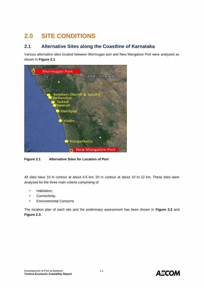
Various alternative sites located between Mormugao port and New Mangalore Port were analysed asshown in Figure 2.1.
Figure 2.1 Alternative Sites for Location of Port
All sites have 10 m contour at about 4-5 km; 20 m contour at about 10 to 12 km. These sites wereanalyzed for the three main criteria comprising of:
· Habitation,· Connectivity,· Environmental Concerns
The location plan of each site and the preliminary assessment has been shown in Figure 2.2 andFigure 2.3.
Development of Port at Belekeri 2-2Techno-Economic Feasibility Report
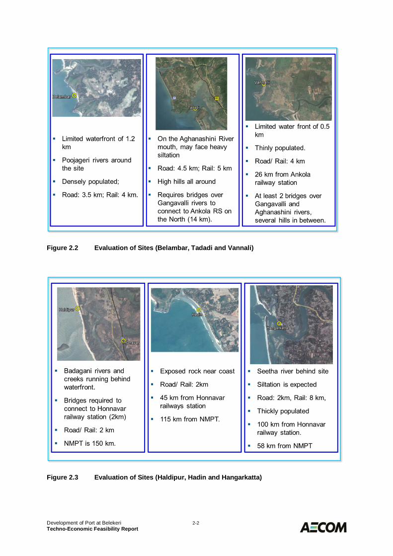
Figure 2.2 Evaluation of Sites (Belambar, Tadadi and Vannali)
Figure 2.3 Evaluation of Sites (Haldipur, Hadin and Hangarkatta)
Development of Port at Belekeri 2-3Techno-Economic Feasibility Report
Out of these sites, two suitable sites are identified in order of preference Belekeri and Vannali (KumtaBeach). Considering the proximity of Belekeri to the proposed Hubli Ankola rail connection, this sitehas been shortlisted for the port development.
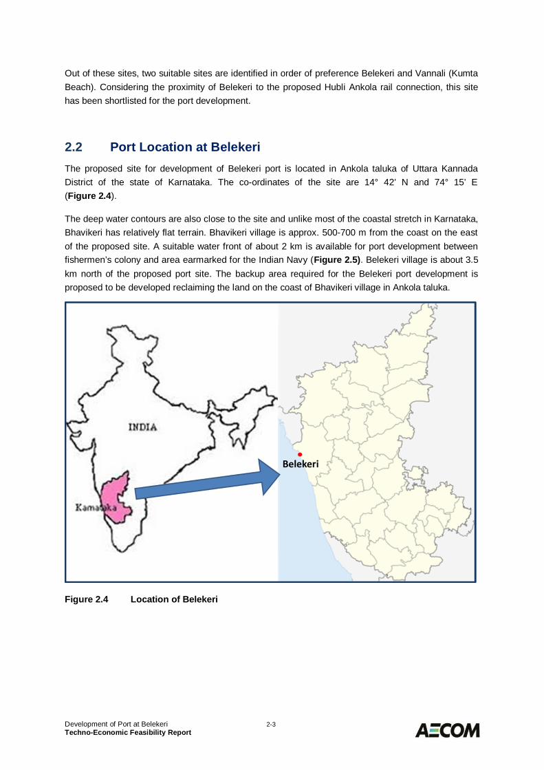
Port Location at Belekeri2.2The proposed site for development of Belekeri port is located in Ankola taluka of Uttara KannadaDistrict of the state of Karnataka. The co-ordinates of the site are 14° 42’ N and 74° 15’ E(Figure 2.4).
The deep water contours are also close to the site and unlike most of the coastal stretch in Karnataka,Bhavikeri has relatively flat terrain. Bhavikeri village is approx. 500-700 m from the coast on the eastof the proposed site. A suitable water front of about 2 km is available for port development betweenfishermen’s colony and area earmarked for the Indian Navy (Figure 2.5). Belekeri village is about 3.5km north of the proposed port site. The backup area required for the Belekeri port development isproposed to be developed reclaiming the land on the coast of Bhavikeri village in Ankola taluka.
Figure 2.4 Location of Belekeri
Development of Port at Belekeri 2-4Techno-Economic Feasibility Report
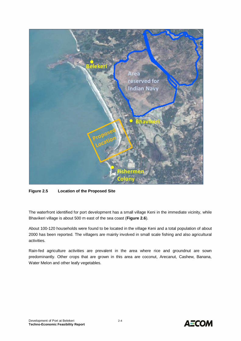
Figure 2.5 Location of the Proposed Site
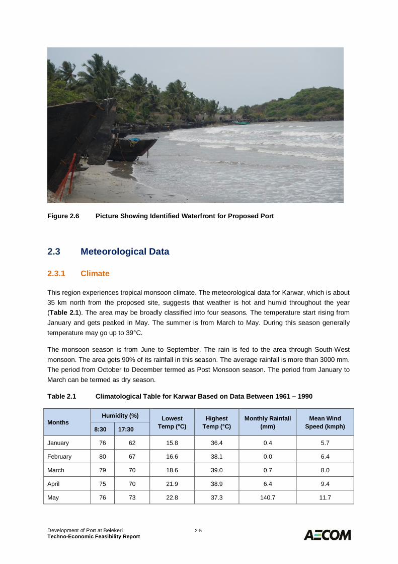
The waterfront identified for port development has a small village Keni in the immediate vicinity, whileBhavikeri village is about 500 m east of the sea coast (Figure 2.6).
About 100-120 households were found to be located in the village Keni and a total population of about2000 has been reported. The villagers are mainly involved in small scale fishing and also agriculturalactivities.
Rain-fed agriculture activities are prevalent in the area where rice and groundnut are sownpredominantly. Other crops that are grown in this area are coconut, Arecanut, Cashew, Banana,Water Melon and other leafy vegetables.
Development of Port at Belekeri 2-5Techno-Economic Feasibility Report
Figure 2.6 Picture Showing Identified Waterfront for Proposed Port
Meteorological Data2.3
Climate2.3.1
This region experiences tropical monsoon climate. The meteorological data for Karwar, which is about35 km north from the proposed site, suggests that weather is hot and humid throughout the year(Table 2.1). The area may be broadly classified into four seasons. The temperature start rising fromJanuary and gets peaked in May. The summer is from March to May. During this season generallytemperature may go up to 39°C.
The monsoon season is from June to September. The rain is fed to the area through South-Westmonsoon. The area gets 90% of its rainfall in this season. The average rainfall is more than 3000 mm.The period from October to December termed as Post Monsoon season. The period from January toMarch can be termed as dry season.
Table 2.1 Climatological Table for Karwar Based on Data Between 1961 – 1990
MonthsHumidity (%) Lowest
Temp (°C)Highest
Temp (°C)Monthly Rainfall
(mm)Mean Wind
Speed (kmph)8:30 17:30
January 76 62 15.8 36.4 0.4 5.7
February 80 67 16.6 38.1 0.0 6.4
March 79 70 18.6 39.0 0.7 8.0
April 75 70 21.9 38.9 6.4 9.4
May 76 73 22.8 37.3 140.7 11.7
Development of Port at Belekeri 2-6Techno-Economic Feasibility Report
MonthsHumidity (%) Lowest
Temp (°C)Highest
Temp (°C)Monthly Rainfall
(mm)Mean Wind
Speed (kmph)8:30 17:30
June 87 82 22.1 35.0 916.7 11.3
July 88 85 22.2 32.1 926.6 14.2
August 89 85 22.3 31.1 671.7 11.4
September 89 82 22.0 32.7 312.1 7.1
October 85 77 20.6 36.4 140.3 5.3
November 75 69 17.7 36.4 31.2 4.6
December 72 62 16.1 36.0 16.8 4.9
Average 81 74 14.8 39.0 3163.5 8.3
[Source: IMD, 2010]
Visibility2.3.2
Visibility in the region is good throughout the year and is generally greater than 4 km. However, duringthe rainy season, the visibility is likely to be reduced when the rainfall intensity is high.
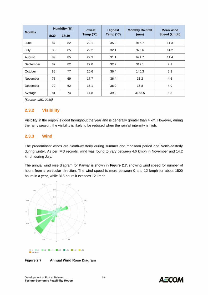
Wind2.3.3
The predominant winds are South-westerly during summer and monsoon period and North-easterlyduring winter. As per IMD records, wind was found to vary between 4.6 kmph in November and 14.2kmph during July.
The annual wind rose diagram for Karwar is shown in Figure 2.7, showing wind speed for number ofhours from a particular direction. The wind speed is more between 0 and 12 kmph for about 1500hours in a year, while 315 hours it exceeds 12 kmph.
Figure 2.7 Annual Wind Rose Diagram
Development of Port at Belekeri 2-7Techno-Economic Feasibility Report
Cyclones2.3.4
In general the west coast of India is less prone to cyclonic storms compared to the east coast. Fromthe information reported by India Meteorological Department (IMD), only 25% of the cyclones thatdevelop over the Arabian Sea approach the west coast. It is observed from the tracks of the cyclonesin the Arabian Sea from 1877 to 2012 that only one cyclone hit the Uttara Kannada district in a periodof 110 years.
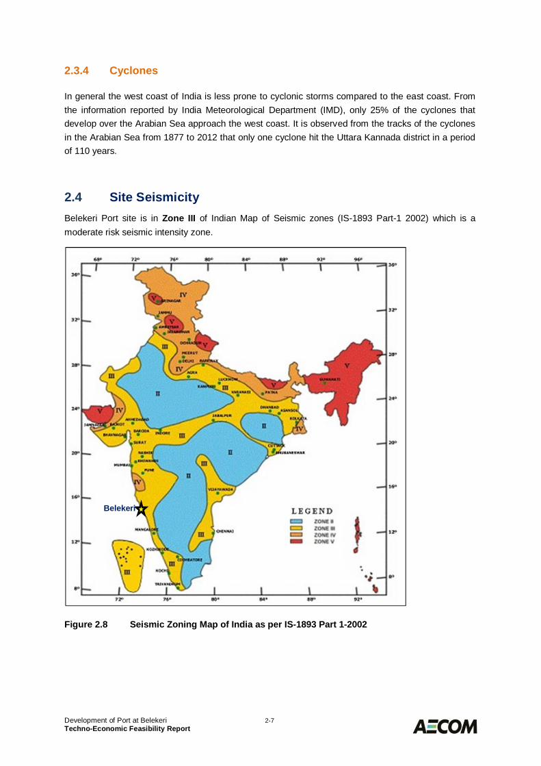
Site Seismicity2.4Belekeri Port site is in Zone III of Indian Map of Seismic zones (IS-1893 Part-1 2002) which is amoderate risk seismic intensity zone.
Figure 2.8 Seismic Zoning Map of India as per IS-1893 Part 1-2002
Belekeri
Development of Port at Belekeri 2-8Techno-Economic Feasibility Report
Oceanographic Information2.5
Tide Levels2.5.1
The tide at Belekeri is semidiurnal with two high tides and two low tides in a day. The tidal elevationsreferred to chart datum at Belekeri is as in Table 2.2.
Table 2.2 Tide levels
Tidal Datum Elevation (m, CD)
Highest High Water Spring (HHWS) +2.13
Mean High Water Springs (MHWS) +1.90
Mean High Water Neaps (MHWN) +1.64
Mean Sea Level (MSL) +1.13
Mean Low Water Neaps (MLWN) +0.92
Mean Low Water Springs (MLWS) +0.32
Lowest Low Water Spring (LLWS) +0.04
Wave Conditions2.5.2
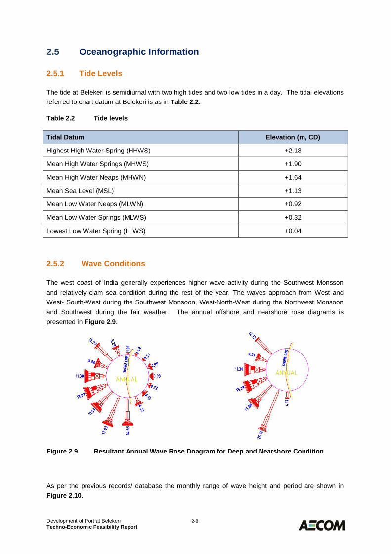
The west coast of India generally experiences higher wave activity during the Southwest Monssonand relatively clam sea condition during the rest of the year. The waves approach from West andWest- South-West during the Southwest Monsoon, West-North-West during the Northwest Monsoonand Southwest during the fair weather. The annual offshore and nearshore rose diagrams ispresented in Figure 2.9.
Figure 2.9 Resultant Annual Wave Rose Doagram for Deep and Nearshore Condition
As per the previous records/ database the monthly range of wave height and period are shown inFigure 2.10.
Development of Port at Belekeri 2-9Techno-Economic Feasibility Report
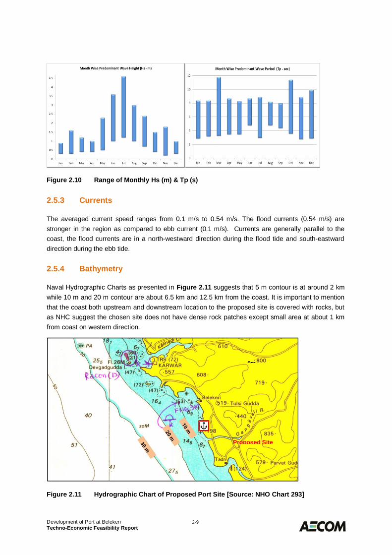
Figure 2.10 Range of Monthly Hs (m) & Tp (s)
Currents2.5.3
The averaged current speed ranges from 0.1 m/s to 0.54 m/s. The flood currents (0.54 m/s) arestronger in the region as compared to ebb current (0.1 m/s). Currents are generally parallel to thecoast, the flood currents are in a north-westward direction during the flood tide and south-eastwarddirection during the ebb tide.
Bathymetry2.5.4
Naval Hydrographic Charts as presented in Figure 2.11 suggests that 5 m contour is at around 2 kmwhile 10 m and 20 m contour are about 6.5 km and 12.5 km from the coast. It is important to mentionthat the coast both upstream and downstream location to the proposed site is covered with rocks, butas NHC suggest the chosen site does not have dense rock patches except small area at about 1 kmfrom coast on western direction.
Figure 2.11 Hydrographic Chart of Proposed Port Site [Source: NHO Chart 293]
0m
Proposed Site
Development of Port at Belekeri 2-10Techno-Economic Feasibility Report
Littoral Drift2.6The longshore sediment transport is observed to be from north to south from March to September andfrom south to north the rest of the year. The yearly net longshore sediment transport is approximately70,000 m3/year southwards.
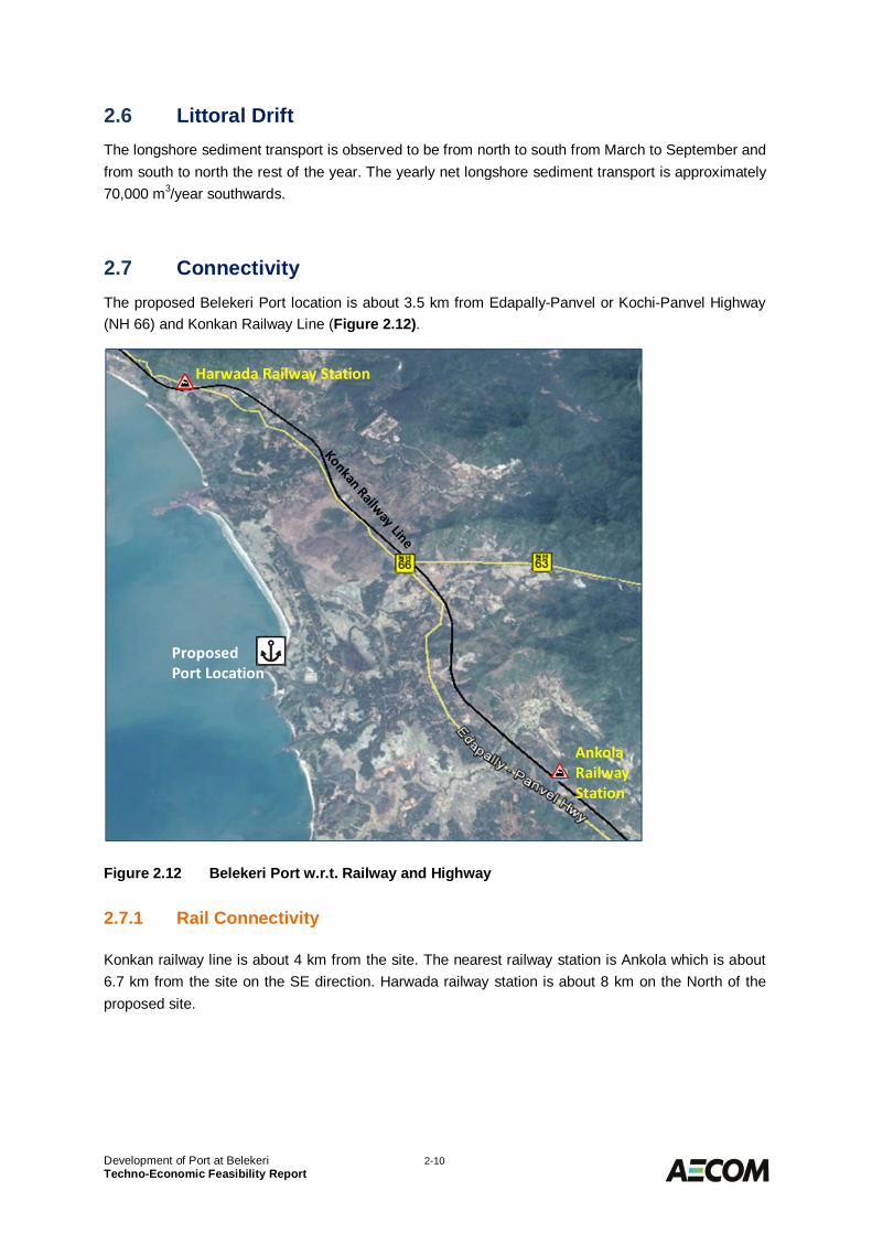
Connectivity2.7The proposed Belekeri Port location is about 3.5 km from Edapally-Panvel or Kochi-Panvel Highway(NH 66) and Konkan Railway Line (Figure 2.12).
Figure 2.12 Belekeri Port w.r.t. Railway and Highway
Rail Connectivity2.7.1
Konkan railway line is about 4 km from the site. The nearest railway station is Ankola which is about6.7 km from the site on the SE direction. Harwada railway station is about 8 km on the North of theproposed site.
Development of Port at Belekeri 2-11Techno-Economic Feasibility Report
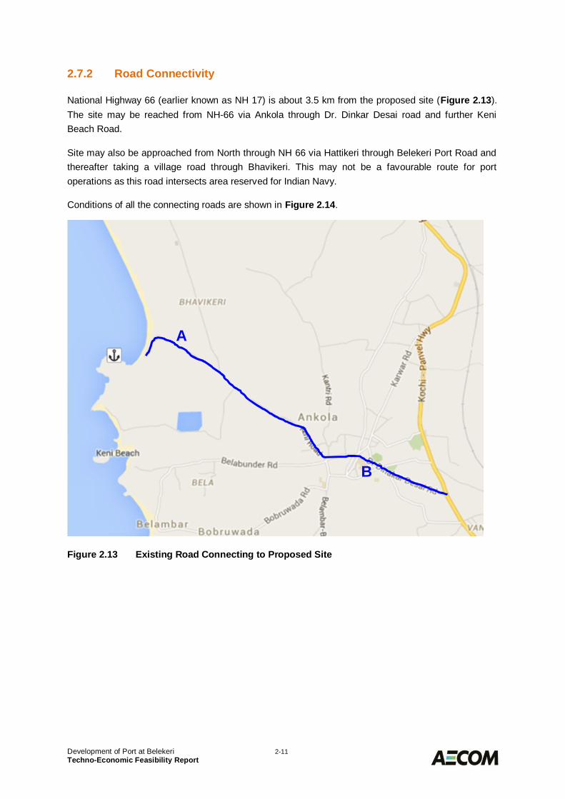
Road Connectivity2.7.2
National Highway 66 (earlier known as NH 17) is about 3.5 km from the proposed site (Figure 2.13).The site may be reached from NH-66 via Ankola through Dr. Dinkar Desai road and further KeniBeach Road.
Site may also be approached from North through NH 66 via Hattikeri through Belekeri Port Road andthereafter taking a village road through Bhavikeri. This may not be a favourable route for portoperations as this road intersects area reserved for Indian Navy.
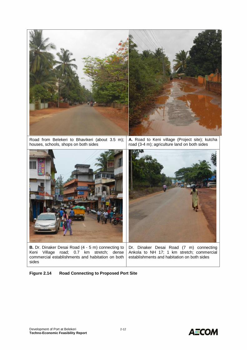
Conditions of all the connecting roads are shown in Figure 2.14.
Figure 2.13 Existing Road Connecting to Proposed Site
A
B
Development of Port at Belekeri 2-12Techno-Economic Feasibility Report
Road from Belekeri to Bhavikeri (about 3.5 m);houses, schools, shops on both sides
A. Road to Keni village (Project site); kutcharoad (3-4 m); agriculture land on both sides
B. Dr. Dinaker Desai Road (4 - 5 m) connecting toKeni Village road; 0.7 km stretch; densecommercial establishments and habitation on bothsides
Dr. Dinaker Desai Road (7 m) connectingAnkola to NH 17; 1 km stretch; commercialestablishments and habitation on both sides
Figure 2.14 Road Connecting to Proposed Port Site
Development of Port at Belekeri 2-13Techno-Economic Feasibility Report
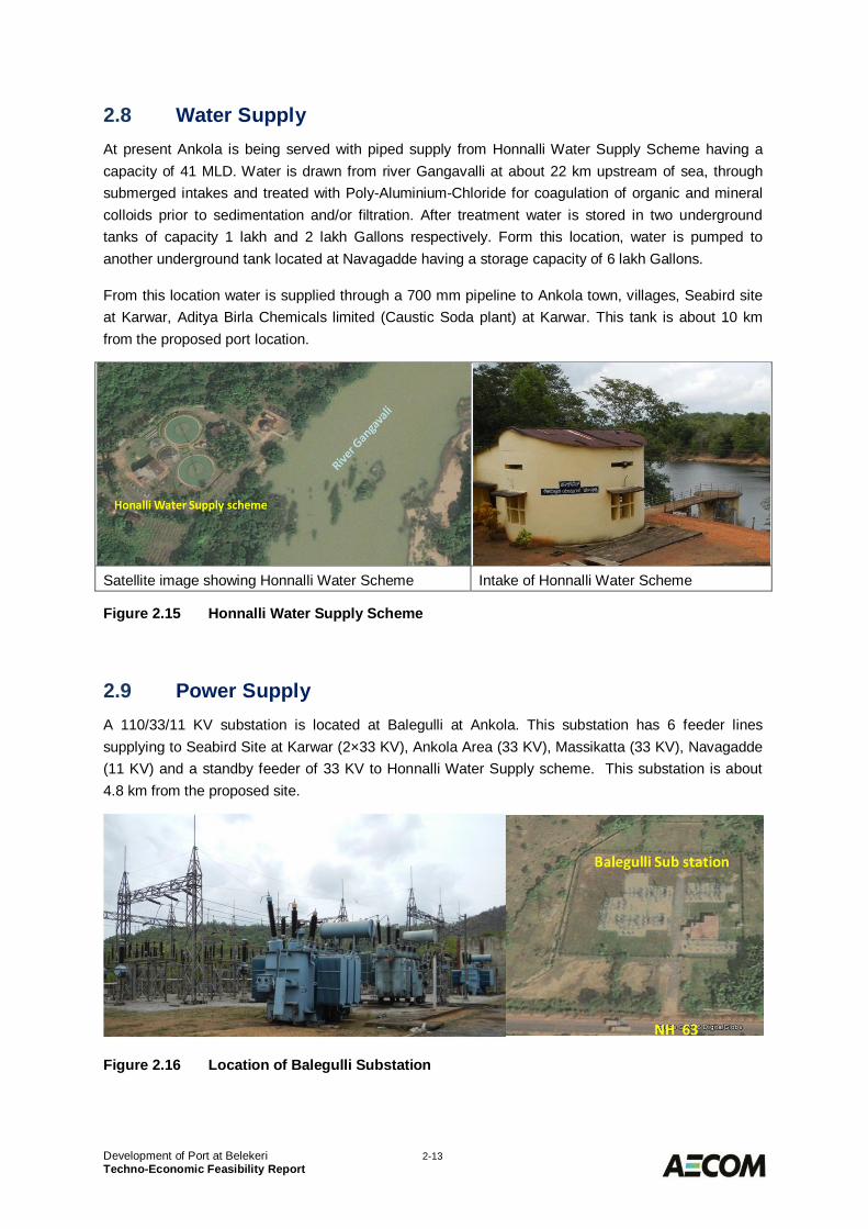
Water Supply2.8At present Ankola is being served with piped supply from Honnalli Water Supply Scheme having acapacity of 41 MLD. Water is drawn from river Gangavalli at about 22 km upstream of sea, throughsubmerged intakes and treated with Poly-Aluminium-Chloride for coagulation of organic and mineralcolloids prior to sedimentation and/or filtration. After treatment water is stored in two undergroundtanks of capacity 1 lakh and 2 lakh Gallons respectively. Form this location, water is pumped toanother underground tank located at Navagadde having a storage capacity of 6 lakh Gallons.
From this location water is supplied through a 700 mm pipeline to Ankola town, villages, Seabird siteat Karwar, Aditya Birla Chemicals limited (Caustic Soda plant) at Karwar. This tank is about 10 kmfrom the proposed port location.
Satellite image showing Honnalli Water Scheme Intake of Honnalli Water Scheme
Figure 2.15 Honnalli Water Supply Scheme
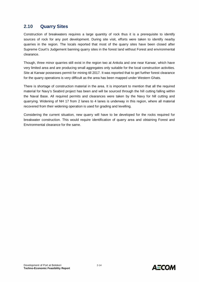
Power Supply2.9A 110/33/11 KV substation is located at Balegulli at Ankola. This substation has 6 feeder linessupplying to Seabird Site at Karwar (2×33 KV), Ankola Area (33 KV), Massikatta (33 KV), Navagadde(11 KV) and a standby feeder of 33 KV to Honnalli Water Supply scheme. This substation is about4.8 km from the proposed site.
Figure 2.16 Location of Balegulli Substation
Development of Port at Belekeri 2-14Techno-Economic Feasibility Report
Quarry Sites2.10Construction of breakwaters requires a large quantity of rock thus it is a prerequisite to identifysources of rock for any port development. During site visit, efforts were taken to identify nearbyquarries in the region. The locals reported that most of the quarry sites have been closed afterSupreme Court’s Judgement banning quarry sites in the forest land without Forest and environmentalclearance.
Though, three minor quarries still exist in the region two at Ankola and one near Karwar, which havevery limited area and are producing small aggregates only suitable for the local construction activities.Site at Karwar possesses permit for mining till 2017. It was reported that to get further forest clearancefor the quarry operations is very difficult as the area has been mapped under Western Ghats.
There is shortage of construction material in the area. It is important to mention that all the requiredmaterial for Navy’s Seabird project has been and will be sourced through the hill cutting falling withinthe Naval Base. All required permits and clearances were taken by the Navy for hill cutting andquarrying. Widening of NH 17 from 2 lanes to 4 lanes is underway in this region, where all materialrecovered from their widening operation is used for grading and levelling.
Considering the current situation, new quarry will have to be developed for the rocks required forbreakwater construction. This would require identification of quarry area and obtaining Forest andEnvironmental clearance for the same.
Development of Port at Belekeri 3-1Techno-Economic Feasibility Report
TRAFFIC PROJECTIONS3.0General3.1
The origin-destination of key cargo for port at Belekeri and development of traffic scenarios for aperiod of 20 years has been carried out by McKinsey & Co. as mandated for this project.
This section covers the traffic projections for the proposed port of Belekeri. The proposed port site ofBelekeri lies on the western coast of India in state of Karnataka. It has operational major ports ofMormugao on the north and Mangalore port on the south.
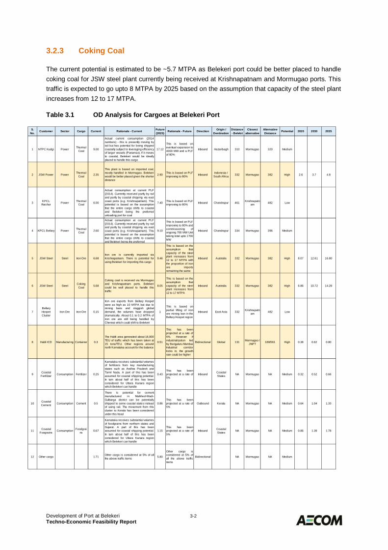
Major Commodities and their Projections3.2Thermal coal, iron ore and coking coal would be the key commodities that can be catered to by theproposed port. Each of the possible cargo centres in the hinterland for the proposed port has beenmapped to assess whether the proposed port at Belekeri could be a gateway for their traffic. Thedetails are attached in Table 3.1.
Thermal Coal3.2.1
The proposed port has a current potential of attracting attract traffic of ~2.3 MTPA which can go upto 3MTPA by 2025.
This is based on the assumption that for JSW power, the plant is based on imported coal, mostlyhandled in Mormugao. The current potential is estimated on the basis of Belekeri being better placedgiven the shorter distance.
In future, the potential has been estimated assuming plants operate at 80% PLF.
Iron Ore3.2.2
The port is expected to divert part of the traffic currently handled primarily by Krishnapatnam port.JSW steel currently imports iron ore at Krishnapatnam. There is potential for using Belekeri forimporting this cargo. Hence the current potential of port to handle iron ore is around 6.8 MTPA. Thistraffic could go up to ~9.5 MTPA based on the assumption that capacity of the JSW steel plantincreases from 12 to 17 MTPA with the proportion of iron ore imports remaining the same.
Belekeri port would be better placed to handle iron ore moving inbound to Bellary as compared toKrishnapatnam as the distance from Belekeri to Bellary is significantly lesser than the distancebetween Bellary and Krishnapatnam port. This will result in reduced logistic costs if Belekeri portbecomes the primary port to handle iron ore traffic. It is to be noted that this estimation is contingenton the implementation of the proposed rail line between Hubli and Ankola and Ankola and Belekeriport.
Development of Port at Belekeri 3-2Techno-Economic Feasibility Report
Coking Coal3.2.3
The current potential is estimated to be ~5.7 MTPA as Belekeri port could be better placed to handlecoking coal for JSW steel plant currently being received at Krishnapatnam and Mormugao ports. Thistraffic is expected to go upto 8 MTPA by 2025 based on the assumption that capacity of the steel plantincreases from 12 to 17 MTPA.
Table 3.1 OD Analysis for Cargoes at Belekeri Port
S.No.
Customer Sector Cargo Current Rationale - Current Future(2025)
Rationale - Future Direction Origin /Destination
Distance- Belekri
Closestalternative
AlternativeDistance
Potential 2020 2030 2035
1 NTPC Kudgi Power ThermalCoal 9.00
Actual current consumption (2014numbers) - this is presently moving byrail but has potential for being shippedcoastally subject to leveraging efficiencyof larger vessels (Panamax). If it movesto coastal, Belekeri would be ideallyplaced to handle this cargo
17.12
This is based oneventual expansion to4000 MW and a PLFof 80%
Inbound Hazaribagh 310 Mormugao 320 Medium
2 JSW Power Power ThermalCoal 2.35
This plant is based on imported coal,mostly handled in Mormugao. Belekeriwould be better placed given the shorterdistance
2.90 This is based on PLFimproving to 80% Inbound Indonesia /
South Africa 332 Mormugao 382 High 2.6 3.7 4.8
3 KPCLRaichur Power Thermal
Coal 6.00
Actual consumption at current PLF(2014). Currently received partly by railand partly by coastal shipping via eastcoast ports (e.g. Krishnapatnam). Thispotential is based on the assumptionthat the entire cargo shifts to coastaland Belekeri being the preferredunloading port for coal
7.40 This is based on PLFimproving to 80% Inbound Chandrapur 461 Krishnapatn
am 482 Low
4 KPCL Bellary Power ThermalCoal 2.60
Actual consumption at current PLF(2014). Currently received partly by railand partly by coastal shipping via eastcoast ports (e.g. Krishnapatnam). Thispotential is based on the assumptionthat the entire cargo shifts to coastaland Belekeri being the preferred
9.10
This is based on PLFimproving to 80% andcommissioning ofongoing 700 MW Unittaking total upto 1700MW
Inbound Chandrapur 334 Mormugao 396 Medium
5 JSW Steel Steel Iron Ore 6.68Iron ore is currently imported viaKrishnapatnam. There is potential forusing Belekeri for importing this cargo
9.46
This is based on theassumption thatcapacity of the steelplant increases from12 to 17 MTPA withthe proportion of ironore importsremaining the same
Inbound Australia 332 Mormugao 382 High 8.07 12.61 16.80
6 JSW Steel Steel CokingCoal 5.68
Coking coal is received via Mormugaoand Krishnapatnam ports. Belekericould be well placed to handle thistraffic
8.05
This is based on theassumption thatcapacity of the steelplant increases from12 to 17 MTPA
Inbound Australia 332 Mormugao 382 High 6.86 10.72 14.28
7BellaryHospetCluster
Iron Ore Iron Ore 0.15
Iron ore exports from Bellary Hospetwere as high as 10 MTPA but due tomining bans and sluggish globaldemand, the volumes have droppeddramatically. About 0.1 to 0.2 MTPA ofiron ore are still being handled byChennai which could shift to Belekeri
1
This is based onpartial lifting of ironore mining ban in theBellary Hospet region
Inbound East Asia 332 Krishnapatnam 482 Low
8 Hubli ICD Manufacturing Container 0.3
The Hubli area generated about 16,000TEU of traffic which has been taken at15 tons/TEU. Other regions aroundnorth Karnataka account for the balance
0.51
This has beenprojected at a rate of5%. However ifindustrialization ledby Bengaluru MumbaiIndustrial corridorkicks in, the growthrate could be higher
Bidirectional Global 131 Mormugao /JNPT 188/561 High 0.38 0.62 0.80
9 CoastalFertilizer Consumption Fertilizer 0.25
Karnataka receives substantial volumesof fertilizers from key manufacturingstates such as Andhra Pradesh andTamil Nadu. A part of this has beenassumed for coastal shipping potential.In turn about half of this has beenconsidered for Uttara Kanara regionwhich Belekeri can handle
0.43This has beenprojected at a rate of5%
Inbound CoastalStates NA Mormugao NA Medium 0.32 0.52 0.66
10 CoastalCement Consumption Cement 0.5
There is potential for cementmanufactured in Malkhed-Wadi-Gulbarga district can be potentiallyshipped to some coastal states insteadof using rail. The movement from thiscluster to Kerala has been consideredunder this head
0.86This has beenprojected at a rate of5%
Outbound Kerala NA Mormugao NA Medium 0.64 1.04 1.33
11 CoastalFoograins Consumption Foodgrai
ns 0.67
Karnataka receives substantial volumesof foodgrains from northern states andGujarat. A part of this has beenassumed for coastal shipping potential.In turn about half of this has beenconsidered for Uttara Kanara regionwhich Belekeri can handle
1.15This has beenprojected at a rate of5%
Inbound CoastalStates NA Mormugao NA Medium 0.86 1.39 1.78
12 Other cargo 1.71 Other cargo is considered at 5% of allthe above traffic items 5.80
Other cargo isconsidered at 5% ofall the above trafficitems
Bidirectional NA Mormugao NA Medium
Development of Port at Belekeri 3-3Techno-Economic Feasibility Report
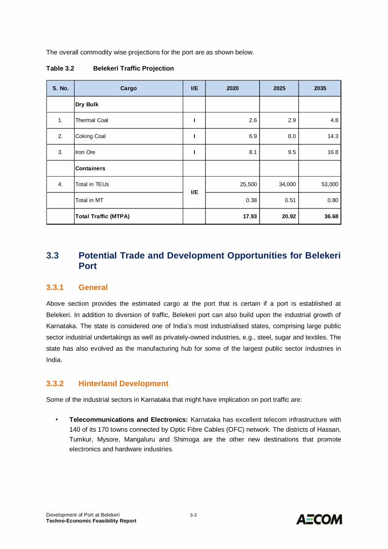
The overall commodity wise projections for the port are as shown below.
Table 3.2 Belekeri Traffic Projection
Potential Trade and Development Opportunities for Belekeri3.3Port
General3.3.1
Above section provides the estimated cargo at the port that is certain if a port is established at
Belekeri. In addition to diversion of traffic, Belekeri port can also build upon the industrial growth of
Karnataka. The state is considered one of India’s most industrialised states, comprising large public
sector industrial undertakings as well as privately-owned industries, e.g., steel, sugar and textiles. The
state has also evolved as the manufacturing hub for some of the largest public sector industries in
India.
Hinterland Development3.3.2
Some of the industrial sectors in Karnataka that might have implication on port traffic are:
· Telecommunications and Electronics: Karnataka has excellent telecom infrastructure with140 of its 170 towns connected by Optic Fibre Cables (OFC) network. The districts of Hassan,Tumkur, Mysore, Mangaluru and Shimoga are the other new destinations that promoteelectronics and hardware industries.
S. No. Cargo I/E 2020 2025 2035
Dry Bulk
1. Thermal Coal I 2.6 2.9 4.8
2. Coking Coal I 6.9 8.0 14.3
3. Iron Ore I 8.1 9.5 16.8
Containers
4. Total in TEUs 25,500 34,000 53,000
Total in MT 0.38 0.51 0.80
Total Traffic (MTPA) 17.93 20.92 36.68
I/E
Development of Port at Belekeri 3-4Techno-Economic Feasibility Report
· Automotive: Karnataka has a vibrant auto industry with investments of around USD 713 mnand annual revenues of USD 604 mn. The sector grew at a CAGR of 15 per cent from 2009 to2014. The main locations for automobile industries are Bengaluru, Ramanagara, Kolar,Shimoga, Dharwad and Belgaum. It also has three auto clusters, one industrial valve clusterand one auto component cluster. Two manufacturing hubs are being developed in theNarsapur and Vemagal industrial areas in Kolar District.
· Textiles: Karnataka contributes over 20 per cent of the national garment production and 45per cent of the national raw silk production. It is a major apparel sourcing destination for theglobal market. It is one of the leading producers of the key raw materials required for textilemanufacturing units. According to the New Textile Policy 2013–18, the Karnataka governmentis planning to invest USD 1,650 mn in the sector.
· Aerospace: The state has been seen as the pioneer in the Indian aerospace industry. Thestate government plans to invest around USD 1.7 bn to develop an aerospace park. Furtherinvestment potential of USD 12.5 bn in this sector in the period from 2013 to 2023 has beenidentified and there are plans to develop aerospace clusters in different regions of the state.
· Chemicals and Petrochemicals: Karnataka has been trying to position itself as a majorgrowth centre for the chemical industry with the presence of around 500 companies, such asMRPL and BASF. Mangaluru is evolving as the focal point of all chemical and petrochemicalindustries in the state.
Major Exports3.3.3
Karnataka has a long tradition of overseas trade. While it has historically been a major exporter ofcoffee, spices, silk, cashew nuts and handicrafts, over the last two decades it has emerged as a majorexporter of commodities such as electronics and computer software, engineering goods, readymadegarments, petrochemicals, gems and jewellery, agro and food processing products, chemicals,minerals and ores and marine products.
As of 2014–15, total exports from Karnataka reached around USD 52.02 bn, approximately 13.01 percent of India’s total exports. The state’s exports increased at a CAGR of 9.4 per cent from 2010–11 to2014–15.
Some of the exports that can have impact on traffic at ports are –
· The engineering segment is the fastest growing sector of the state, seeing a 21.3 per centCAGR growth between 2010–11 and 2014–15. Exports of engineering products increasedfrom USD 1,605 mn in 2010–11 to USD 3,476.8 mn in 2014–15. The state is exportingengineering products to Germany, China, South Korea, Brazil, the US, Malaysia, Thailand,South Africa and Singapore. Exports include machine tools, industrial machinery, cutting tools,castings, automotive components, electrodes, welding equipment, construction andearthmoving equipment, and helicopter spares.
· Karnataka leads in the exports of silk in India accounting for approximately 25 per cent of thetotal Indian export market.
· Export of agriculture and processed food in the state grew at a CAGR of 11.8 per centbetween 2010–11 and 2014–15. The export value increased from USD 146.9 mn in 2010–11to USD 229.4 mn in 2014–15.

Development of Port at Belekeri 4-1Techno-Economic Feasibility Report
DESIGN SHIP SIZES4.0General4.1
The size of ships that would call at any port will generally be governed by the following aspects:
· The trading route· Availability of a suitable ship in the market· Available facilities mainly navigational channel and manoeuvring areas including the draft· The available facilities for loading & unloading· Volume and type of annual traffic to be handled and the likely parcel size as per the
requirements of the users.
The following main cargo commodities for the proposed Belekeri have been identified as:
· Thermal/ Coking Coal· Iron Ore· Containers
Dry Bulk Ships4.2Dry Bulk as Coal and Iron ore are the main cargo commodities that are proposed to be handled at theproposed Belekeri Port. While selecting the design ship size, in addition to ascertaining the freightadvantage of larger vessels, it is essential to study the origin/destination ports and the facilitiesavailable there for handling large carriers.
For dry bulk cargo, carriers are generally classified into the following groups:
Handysize : 10,000–40,000 DWT
Handymax : 40,000–60,000 DWT
Panamax : 60,000–80,000 DWT
Cape : 80,000–120,000 DWT
Super cape : Over 120,000 DWT with the largest carrier being 400,000 DWT
Coal and Coking coal is to be imported to the area, for which Panamax vessels for the immediatephase and Cape size are considered for the year 2035. For Iron Import, Panamax size vessels arerecommended for all the phases.
Development of Port at Belekeri 4-2Techno-Economic Feasibility Report
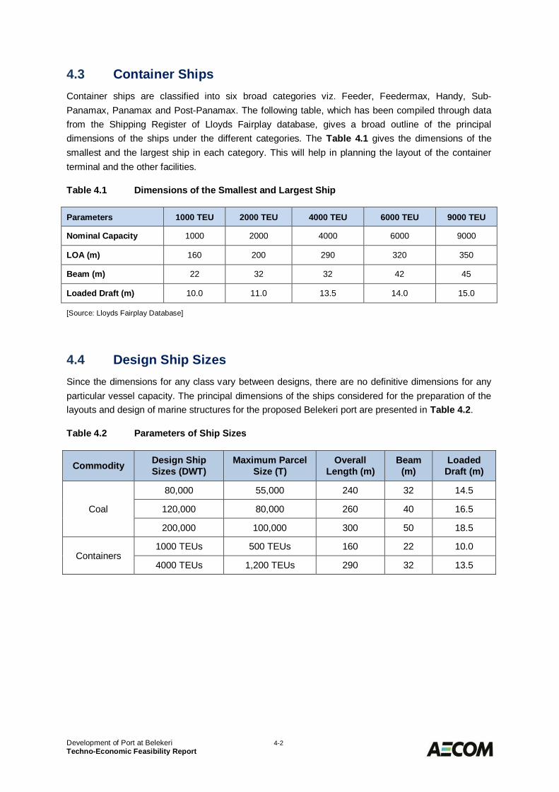
Container Ships4.3Container ships are classified into six broad categories viz. Feeder, Feedermax, Handy, Sub-Panamax, Panamax and Post-Panamax. The following table, which has been compiled through datafrom the Shipping Register of Lloyds Fairplay database, gives a broad outline of the principaldimensions of the ships under the different categories. The Table 4.1 gives the dimensions of thesmallest and the largest ship in each category. This will help in planning the layout of the containerterminal and the other facilities.
Table 4.1 Dimensions of the Smallest and Largest Ship
Parameters 1000 TEU 2000 TEU 4000 TEU 6000 TEU 9000 TEU
Nominal Capacity 1000 2000 4000 6000 9000
LOA (m) 160 200 290 320 350
Beam (m) 22 32 32 42 45
Loaded Draft (m) 10.0 11.0 13.5 14.0 15.0
[Source: Lloyds Fairplay Database]
Design Ship Sizes4.4Since the dimensions for any class vary between designs, there are no definitive dimensions for anyparticular vessel capacity. The principal dimensions of the ships considered for the preparation of thelayouts and design of marine structures for the proposed Belekeri port are presented in Table 4.2.
Table 4.2 Parameters of Ship Sizes
Commodity Design ShipSizes (DWT)
Maximum ParcelSize (T)
OverallLength (m)
Beam(m)
LoadedDraft (m)
Coal
80,000 55,000 240 32 14.5
120,000 80,000 260 40 16.5
200,000 100,000 300 50 18.5
Containers1000 TEUs 500 TEUs 160 22 10.0
4000 TEUs 1,200 TEUs 290 32 13.5
Development of Port at Belekeri 5-1Techno-Economic Feasibility Report
PORT FACILITY REQUIREMENTS5.0General5.1
The layout of any port will be based on the requirements in terms of number of berths, navigation aids,material handling equipment, storage area for each type of cargo, road and rail access for the receiptand evacuation of cargo, and other utilities. These requirements have to be worked out fordevelopment in a phased manner to enable preparation of the port’s master plan.
The vessel size for Phase 1 needs to carefully chosen so that the capital investment commensuratewith the traffic forecast. Accordingly, it is proposed to consider the following options for phasing ofport:
1. Initial development for panamax size ships having draft of 14.5 m.
2. Initial development for cape size ships of draft up to 18.3 m
3. Initial development for Panamax size ships and deepening of the channel and harbour basinto handle cape size ships in phase-wise manner as per the market demand.
Considering that the dry bulk would be the key commodity for the proposed port, it is important thatPhase 1 port facilities are able to handle the Panamax ships. Thermal coal is one of the keycommodities for this port which moves through coastal shipping. Most of the quantity for thiscommodity is likely to be moved through panamax size ships and therefore it would make sense tolimit the initial phase development for Panamax size ships only. Also, the other dry bulk expected tothe port is the imported coking coal and iron ore which can be handled in panamax as well as capsizevessels. However, the projections for iron ore and coking coal, which shall be imported, beingsignificant, there is a case for developing this port for cape size ships so as to be in a completiveposition vis a vis Krishnapatnam and Mormugao ports against which the proposed port shall becompeting.
Berth Requirements5.2
General5.2.1
The required number of berths depends mainly on the cargo volumes and the handling rates. Whileconsidering the handling rates for various commodities it must be ensured that they are at par orbetter as compared to the competing facilities so as to be able to attract more cargo. Allowable berthoccupancy, the number of operational days in a year and the parcel sizes of ships are other mainfactors that influence the number of berths.
Development of Port at Belekeri 5-2Techno-Economic Feasibility Report
Cargo Handling Systems5.2.2
Considering the project throughput and the competiveness requirements, the handling systemsassumed for various commodities are described below:
5.2.2.1 Dry Bulk Import
It is proposed to provide a common facility with the fully mechanised handling system for dry bulkimports like thermal and coking coal, iron ore etc. The system comprises of gantry type unloaders atberth, connected conveyor system from berth to yard, stacker and reclaimer at yard and wagonloading system.
5.2.2.2 Breakbulk and Containers
For containers, it is proposed to be handled through mobile harbour cranes with spreaderarrangement. For handling at the container yard, suitable number of Rubber Tyred Gantry Cranes(RTGCs) shall be provided. At the railway yard reach stacker shall be provided for loading andunloading of rakes.
Operational Time5.2.3
Considering that the port is planned as all-weather port, the effective number of working days is takenas 350 days per year, allowing for 15 non-operational days due to weather. Further, it is assumed thatthe port will operate round the clock i.e. three shifts of eight hours each. This results in an effectiveworking of 20 hours a day.
Time Required for Peripheral Activities5.2.4
Apart from the time involved in loading / unloading of cargo, additional time is required for peripheralactivities such as berthing and de-berthing of the vessels, customs clearance, cargo surveys,positioning and hook up of equipment, waiting for clearance to sail, etc. An average of 4 hours pervessel call has been assumed for these activities.
Allowable Levels of Berth Occupancy5.2.5
Berth occupancy is expressed as the ratio of the total number of days per year that a berth is occupiedby a vessel (including the time spent in peripheral activities) to the number of port operational days ina year. High levels of berth occupancy will result in bunching of ships resulting in undesirable pre-berthing detention.
In order to be competitive, it is important that the ships calling at the port should have minimal pre-berthing detention. At the same time the investment at the port infrastructure has to be kept at optimallevel. Keeping these in consideration it is proposed to limit berth occupancy of 60% for 1 berth andthat 65% for 2 berths for similar commodity. This shall reduce the pre-berthing detention of ships andoffer reduced logistics cost to the shippers.
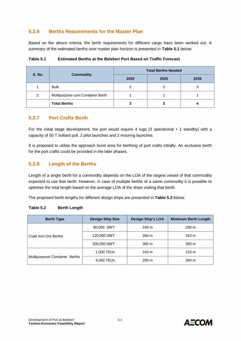
Development of Port at Belekeri 5-3Techno-Economic Feasibility Report
Berths Requirements for the Master Plan5.2.6
Based on the above criteria, the berth requirements for different cargo have been worked out. Asummary of the estimated berths over master plan horizon is presented in Table 5.1 below:
Table 5.1 Estimated Berths at the Belekeri Port Based on Traffic Forecast
S. No. CommodityTotal Berths Needed
2020 2025 2035
1. Bulk 2 2 3
2. Multipurpose cum Container Berth 1 1 1
Total Berths 3 3 4
Port Crafts Berth5.2.7
For the initial stage development, the port would require 4 tugs (3 operational + 1 standby) with acapacity of 50 T bollard pull, 2 pilot launches and 2 mooring launches.
It is proposed to utilise the approach bund area for berthing of port crafts initially. An exclusive berthfor the port crafts could be provided in the later phases.
Length of the Berths5.2.8
Length of a single berth for a commodity depends on the LOA of the largest vessel of that commodityexpected to use that berth. However, in case of multiple berths of a same commodity it is possible tooptimise the total length based on the average LOA of the ships visiting that berth.
The proposed berth lengths for different design ships are presented in Table 5.2 below.
Table 5.2 Berth Length
Berth Type Design Ship Size Design Ship’s LOA Minimum Berth Length
Coal/ Iron Ore Berths
80,000 DWT 240 m 290 m
120,000 DWT 260 m 310 m
200,000 DWT 300 m 350 m
Multipurpose/ Container Berths1,000 TEUs 160 m 210 m
4,000 TEUs 290 m 340 m
Development of Port at Belekeri 5-4Techno-Economic Feasibility Report
Storage Requirements5.3The storage requirement at port for a particular commodity is mainly determined by the dwell time ofthe cargo at port. It is a common practice to assume a dwell time of;
· 30 days for imported bulk cargo,· 30 days for Break bulk cargo,· 5 days for containers on an average.
It should also be ensured that the storage capacity at the port for a particular cargo is at least 1.5times the parcel size so as to allow faster turnaround of the ship.
Other factors to be taken into account in determining the size of the storage areas are stackeddensities, angle of repose, maximum and average stacking height, aisle space, reserve capacityfactor, peaking factor, etc.
Based on the above criteria the storage areas have been worked out for various cargos. The Phase 1storage area works out to about 24 Ha increasing to 49 Ha over the master plan horizon.
Buildings5.4Sufficient buildings as per their functional requirements shall be provided in the port area. Thefollowing buildings are generally envisaged:
Terminal Administration Building5.4.1
It will be a 4 storied building housing the following:
· Administrative offices of various operational departments including documentation space· Canteen· First aid post· Central control room for terminal operations· A VIP floor on top floor to have an overall view of the terminal
Signal Station5.4.2
A signal station with radar and VHF communication facilities will be provided at a suitable locationnear the water front to communicate with the ships calling at the port and control their movements.
Customs Office5.4.3
An office building inside the port area at an appropriate location to accommodate the customs officialswho are required to inspect the ships and give clearance for movement of cargo in and out of thebonded area.
Development of Port at Belekeri 5-5Techno-Economic Feasibility Report
Gate Complex5.4.4
This will be a single storied building for security personnel and shall be provided near the portentrance.
Substations5.4.5
Substation is envisaged to be provided for the proposed bulk terminals, apart from the main receivingsubstation at the terminal boundary.
Worker’s Amenities Building5.4.6
This shall provide locker and store rooms. It will also include bath and lavatory facilities. Separatebuildings for container and bulk terminals are envisaged.
Maintenance Workshops5.4.7
This shall comprise of a workshop plus store room, and an annex building to provide space for officesof the workshop foremen, mechanics, electricians, technicians and the storekeepers and rooms for offduty operational personnel and maintenance labour.
Other Miscellaneous Buildings5.4.8
The following miscellaneous buildings shall also be provided in the port area:
· Fire Station to house firefighting equipment, fire tenders, etc.· Dispensary buildings to be located near the operational areas and provide minimum first aid
services.· Other miscellaneous utility sheds as per requirements of a particular terminal· Port Users Building for allocation to Banking, C&F Agents’ offices· A fuelling station shall be provided to cater to the requirements of ITV’s and other vehicles
used.
Receipt and Evacuation of Cargo5.5
General5.5.1
For the efficient functioning of a port, the essential pre-requisite is the rail and road connectivity for theeffective movement of cargo in and out of the port.
Based on the market assessment and the infrastructure constraints, it is envisaged that the key cargoshall follow the evacuation pattern from Belekeri port, as shown in Table 5.3:
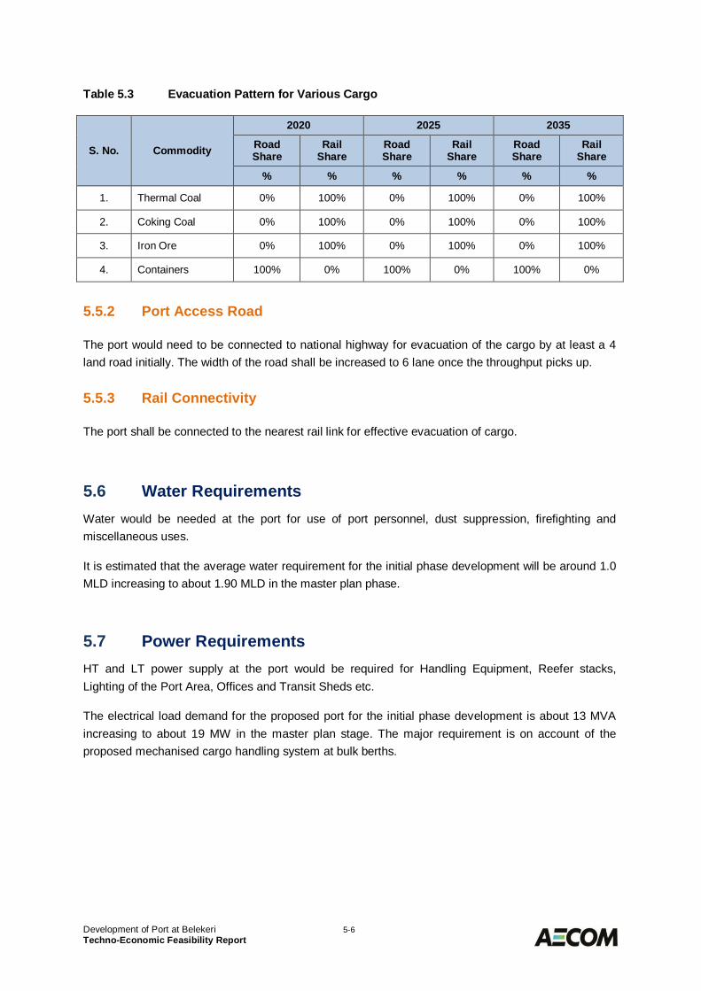
Development of Port at Belekeri 5-6Techno-Economic Feasibility Report
Table 5.3 Evacuation Pattern for Various Cargo
S. No. Commodity
2020 2025 2035
RoadShare
RailShare
RoadShare
RailShare
RoadShare
RailShare
% % % % % %
1. Thermal Coal 0% 100% 0% 100% 0% 100%
2. Coking Coal 0% 100% 0% 100% 0% 100%
3. Iron Ore 0% 100% 0% 100% 0% 100%
4. Containers 100% 0% 100% 0% 100% 0%
Port Access Road5.5.2
The port would need to be connected to national highway for evacuation of the cargo by at least a 4land road initially. The width of the road shall be increased to 6 lane once the throughput picks up.
Rail Connectivity5.5.3
The port shall be connected to the nearest rail link for effective evacuation of cargo.
Water Requirements5.6Water would be needed at the port for use of port personnel, dust suppression, firefighting andmiscellaneous uses.
It is estimated that the average water requirement for the initial phase development will be around 1.0MLD increasing to about 1.90 MLD in the master plan phase.
Power Requirements5.7HT and LT power supply at the port would be required for Handling Equipment, Reefer stacks,Lighting of the Port Area, Offices and Transit Sheds etc.
The electrical load demand for the proposed port for the initial phase development is about 13 MVAincreasing to about 19 MW in the master plan stage. The major requirement is on account of theproposed mechanised cargo handling system at bulk berths.
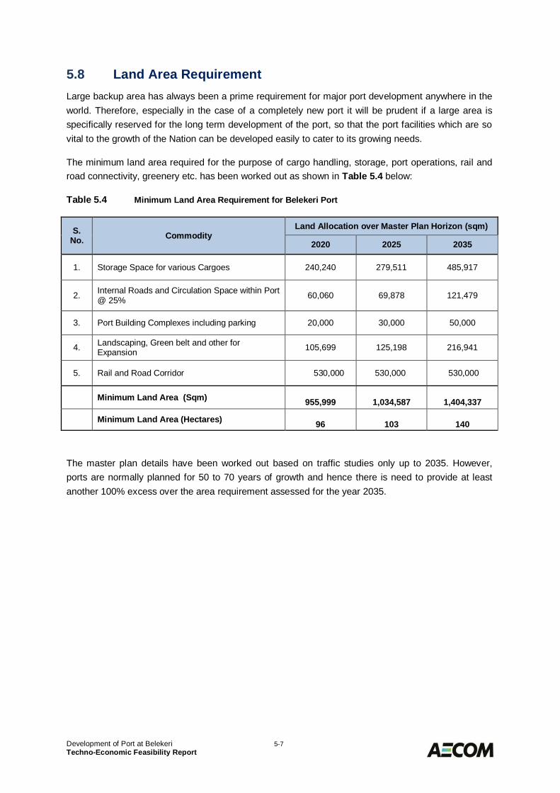
Development of Port at Belekeri 5-7Techno-Economic Feasibility Report
Land Area Requirement5.8Large backup area has always been a prime requirement for major port development anywhere in theworld. Therefore, especially in the case of a completely new port it will be prudent if a large area isspecifically reserved for the long term development of the port, so that the port facilities which are sovital to the growth of the Nation can be developed easily to cater to its growing needs.
The minimum land area required for the purpose of cargo handling, storage, port operations, rail androad connectivity, greenery etc. has been worked out as shown in Table 5.4 below:
Table 5.4 Minimum Land Area Requirement for Belekeri Port
S.No. Commodity
Land Allocation over Master Plan Horizon (sqm)
2020 2025 2035
1. Storage Space for various Cargoes 240,240 279,511 485,917
2. Internal Roads and Circulation Space within Port@ 25% 60,060 69,878 121,479
3. Port Building Complexes including parking 20,000 30,000 50,000
4. Landscaping, Green belt and other forExpansion 105,699 125,198 216,941
5. Rail and Road Corridor 530,000 530,000 530,000
Minimum Land Area (Sqm) 955,999 1,034,587 1,404,337
Minimum Land Area (Hectares) 96 103 140
The master plan details have been worked out based on traffic studies only up to 2035. However,ports are normally planned for 50 to 70 years of growth and hence there is need to provide at leastanother 100% excess over the area requirement assessed for the year 2035.
Development of Port at Belekeri 6-1Techno-Economic Feasibility Report
PREPARATION OF PORT LAYOUT6.0Layout development6.1
The key considerations that are relevant for the establishment of a Greenfield port and its layout aregiven below:
· Potential Traffic;· Techno-economic Feasibility;
o Design ship sizeo Geotechnical Characteristics at siteo Protection from waves and swell to create tranquillity at berthso Availability of material for Reclamation and Breakwater constructiono Adequate manoeuvring area and Channel for the design shipso Scope for expansion beyond the initial developmento Suitability for development in stageso Optimum capital cost of overall development and especially of initial phaseo Flexibility to Expand Beyond Master Plan Horizon
· Land Availability;o Availability of adequate back-up land for storage of cargo and port operationso Rail and Road Connectivity to the Hinterland
· Environmental issues related to development.
Brief Descriptions of Key Considerations6.2The following sub-sections briefly discuss the relative importance and implication of each of the abovefactors in relation to the Greenfield port development at Belekeri.
Potential Traffic6.2.1
The potential traffic that a new port could attract forms the first and foremost requirement of theproject. Considering the site conditions and initial investment needed for creation of the basic portinfrastructure, the projected traffic for the initial phases of development would govern the viability ofport at Belekeri.
Development of Port at Belekeri 6-2Techno-Economic Feasibility Report
Techno-Economic Feasibility6.2.2
6.2.2.1 Design Ship Size
The selection of design ship size is a key input for the port development as the required depths andthe size of the navigational and manoeuvring area of the harbour as well as the cargo handlinginfrastructure are dependent on this. The ship size has direct implication on the cost of the portdevelopment and therefore has impact on the viability. As indicated previously the proposed port hasto compete with the existing Krishnapatnam and Mormugao Ports, both having capabilities (or underexecution) to handle cape size ships, it must be able to cater cape size ships at least in the laterstage of development if not in Phase 1. The initial stage of development it should at least be able tohandle panamax ships size of 80,000 DWT.
6.2.2.2 Geotechnical Characteristics of the Site
The geotechnical characteristics of the site could be a key factor in capital cost of port development.The rock levels at the site will impact the selection of marine layout because of the potentially veryhigh cost of dredging in rock. Similarly very soft soil at the location would also have impact on capitalcost as ground improvement works will have to be resorted to support the structures. Based on thesite information rocky outcrop is observed close to the shore and therefore harbour area has to belocated at a suitable distance away from shore.
6.2.2.3 Protection from Waves and Swell
The location of the port has to be evaluated in terms of the shelter available from the direct attack ofwaves. The locations which are in naturally protected zones do not require expensive breakwaters forprotection from waves for round the year operations. The ports along the west coast are subject towaves from SW direction during southwest monsoons. North east monsoon has least impact in thisregion. The orientation of the breakwaters would need to be decided accordingly.
6.2.2.4 Availability of Construction Material
Transportation cost of the borrowed fill and rock from longer distance forms the major component ofthe overall cost of reclamation and breakwater. The availability of these materials at a nearby locationis favourable to economise the capital cost of port development. During the site visits, as discussed insection 2.10, most of the quarry sites have been abandoned after Supreme Court’s Judgementbanning quarry sites in the forest land without Forest and Environmental Clearance. New quarry sitesneed to be developed for sourcing the material required for breakwater construction and reclamation.This would require identification of quarry area and obtaining Forest and Environmental clearance forthe same.
Development of Port at Belekeri 6-3Techno-Economic Feasibility Report
6.2.2.5 Adequate Manoeuvring Area and Channel for Design Ships
This consideration requires provision of adequate channel width, stopping distance and themanoeuvring area for the design ship, as per the best international practices. The potential of marineaccidents of the ships hitting the berth structure and approach trestle should be eliminated. The widthof the channel would be based on the design ship size as well as requirement for one way or two waychannel.
6.2.2.6 Scope for Expansion Over the Initial Development
With the costly basic infrastructure like breakwater, dredged basin, channel, hinterland connectivity inplace, addition of more berths will not be so capital intensive. This is a likely incentive for investors tocreate additional cargo handling capacity by building new berths/ terminals in future. Therefore theport location and layout should allow for the flexibility for expansion to allow additional berths, storageand evacuation.
6.2.2.7 Flexibility for Development in Stages
The site should allow a development plan such that it is capable of being developed in stages, ifneeded for phase wise induction of cargo handling facilities.
6.2.2.8 Optimum Capital Cost of Overall Development and Especially for the Initial Phase
Capital cost is clearly the primary consideration while evaluating a port location. The cost ofdevelopment of initial phase takes precedence. This aspect shall be duly kept into consideration whiledeciding the design ship size for Phase 1 development so as to minimise the cost of capital dredging.
6.2.2.9 Flexibility for Expansion Beyond Master Plan Horizon
An important and sometimes forgotten aspect of Master Planning is to consider what may happenafter the end of the immediate time horizon of the Master Plan study. The traffic projections for a20 year period inevitably have more inbuilt uncertainty than the more immediate 5 year projections.Therefore the requirements in 2035 may be more than, or less than, or different from, what can bepredicted now. Furthermore, the port traffic will not stop growing in 2035. Therefore, in comparing themerits of different alternatives for Master Plan layout, preference should be given to those that allowspace for further development.

Development of Port at Belekeri 6-4Techno-Economic Feasibility Report
Land Availability6.2.3
6.2.3.1 Availability of Backup Area for Storage of Cargo and Port Operations
Adequate land must be available along the waterfront for an efficient cargo storage and portoperations. Acquiring the land for this purpose may lead to protests from local residents resulting inabandoning of the project or involving significant cost towards land acquisition. Figure 6.1 shows thecurrent pattern of land along the proposed port site. Large chunk of area is reserved for Indian Navybehind Belekeri where no other development can take place. It may be noted that villages viz.,Bhavikeri, Keni, Kolivada are located along the Belekeri bay. In order to avoid any land acquisition andsubsequent R&R issues, it is therefore proposed that backup area of cargo storage and portoperations be planned on reclaimed area.
Figure 6.1 Current Land Pattern along Proposed Site
6.2.3.2 Provision for Rail and Road Connectivity
The onshore cargo storage area should have good connectivity to the external rail and road linkagesfor faster evacuation of cargoes with minimum capital investment and minimum rehabilitation andresettlement. It shall be ensured that the road and rail alignment be selected in such a manner so asto minimise the need for any land acquisition.
Environmental Issues Related to Development6.2.4
The environmental issues such as deforestation, rehabilitation and resettlement would need specialconsideration while arriving at the suitable layout of port.

Development of Port at Belekeri 6-5Techno-Economic Feasibility Report
Planning Criteria6.3
Limiting Wave Conditions for Port Operations6.3.1
6.3.1.1 Pilot Boarding
Ships arriving at the port will take on a pilot to guide it to the designated berth inside the port. The pilotwill normally board the ship at the outer anchorage. Since the pilot has to board the vessel in the opensea through rope ladder along the ship side, the limiting condition is that the significant wave height(Hs) should not exceed 2.5 m. As in the present case the pilots shall be boarding seawards ofnavigational channel and then take the ship to the harbour.
6.3.1.2 Tug Fastening & Tug Operations
The tugs, which assist the ship while stopping, turning in the basin and manoeuvring to the berth,normally meet the vessel in protected water, just inside the breakwaters. The limiting wave conditionfor tugs to fasten to a ship and effectively assist and control the ship varies from Hs=1.0m to Hs=1.5mdepending the type of tugs used.
6.3.1.3 Tranquillity Requirements for Cargo Handling Operations
For carrying out cargo handling operations at the berths, it has to be ensured that there are noexcessive movements of the ships due to wave action that will hamper the ship-shore handlingoperations. This limit varies with the handling system for the different types of cargoes. Hence, thebreakwater configuration and the overall port layout should ensure adequate tranquillity at the berthsso that cargo handling may continue even when the offshore wave climate exceeds the limit for ships’movement in and out of the harbour.
The maximum acceptable wave conditions for cargo handling operations at the berth are dependenton ship size, the type and method of cargo handling and the direction of the wave attack. Beam wavescause the vessel to roll and affect the cargo handling operations more than head waves. The limitingwave height (Hs) from different wave directions for cargo handling operations are stipulated in PIANCbulletin - “Criteria for movements of moored ships in Harbours – a Practical Guide (1995)”. An extractis summarised in Table 6.1 below:
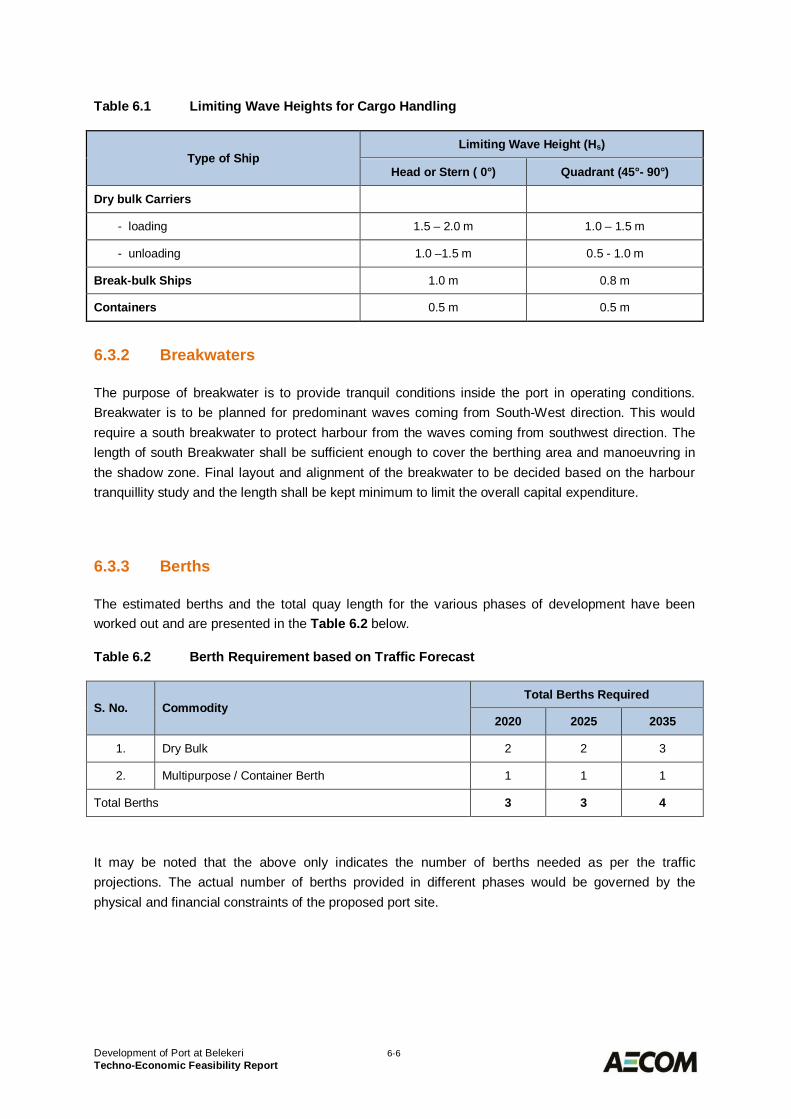
Development of Port at Belekeri 6-6Techno-Economic Feasibility Report
Table 6.1 Limiting Wave Heights for Cargo Handling
Type of ShipLimiting Wave Height (Hs)
Head or Stern ( 0°) Quadrant (45°- 90°)
Dry bulk Carriers
- loading 1.5 – 2.0 m 1.0 – 1.5 m
- unloading 1.0 –1.5 m 0.5 - 1.0 m
Break-bulk Ships 1.0 m 0.8 m
Containers 0.5 m 0.5 m
Breakwaters6.3.2
The purpose of breakwater is to provide tranquil conditions inside the port in operating conditions.Breakwater is to be planned for predominant waves coming from South-West direction. This wouldrequire a south breakwater to protect harbour from the waves coming from southwest direction. Thelength of south Breakwater shall be sufficient enough to cover the berthing area and manoeuvring inthe shadow zone. Final layout and alignment of the breakwater to be decided based on the harbourtranquillity study and the length shall be kept minimum to limit the overall capital expenditure.
Berths6.3.3
The estimated berths and the total quay length for the various phases of development have beenworked out and are presented in the Table 6.2 below.
Table 6.2 Berth Requirement based on Traffic Forecast
S. No. CommodityTotal Berths Required
2020 2025 2035
1. Dry Bulk 2 2 3
2. Multipurpose / Container Berth 1 1 1
Total Berths 3 3 4
It may be noted that the above only indicates the number of berths needed as per the trafficprojections. The actual number of berths provided in different phases would be governed by thephysical and financial constraints of the proposed port site.
Development of Port at Belekeri 6-7Techno-Economic Feasibility Report
Navigational Channel Dimensions6.3.4
The dimensions of the navigation channel to the terminal are dependent on the vessel size, thebehaviour of the vessel when sailing through the channel, required tidal access, the environmentalmaritime conditions (winds, waves, currents) and the channel bottom conditions.
6.3.4.1 Channel Width and Length
The channel width has been calculated from the latest PIANC Guidelines “Harbour ApproachChannels – Design Guidelines: Report No. 121 – 2014”. The detailed calculations are shown inattached Table 6.3.
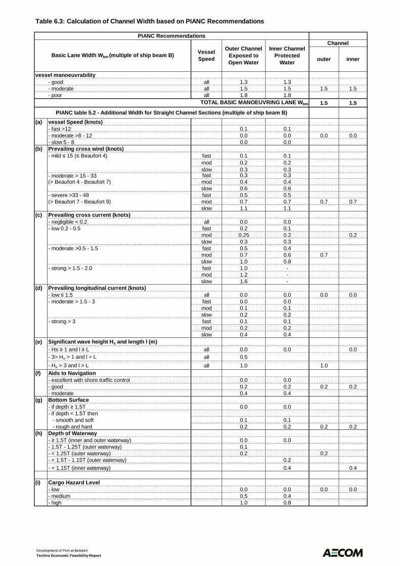
Table 6.3: Calculation of Channel Width based on PIANC Recommendations
outer inner
- good all 1.3 1.3- moderate all 1.5 1.5 1.5 1.5- poor all 1.8 1.8
TOTAL BASIC MANOEUVRING LANE Wbm 1.5 1.5
(a) vessel Speed (knots)- fast >12 0.1 0.1- moderate >8 - 12 0.0 0.0 0.0 0.0- slow 5 - 8 0.0 0.0
(b) Prevailing cross wind (knots)fast 0.1 0.1mod 0.2 0.2slow 0.3 0.3
- moderate > 15 - 33 fast 0.3 0.3(> Beaufort 4 - Beaufort 7) mod 0.4 0.4
slow 0.6 0.6- severe >33 - 48 fast 0.5 0.5(> Beaufort 7 - Beaufort 9) mod 0.7 0.7 0.7 0.7
slow 1.1 1.1(c) Prevailing cross current (knots)
- negligible < 0.2 all 0.0 0.0- low 0.2 - 0.5 fast 0.2 0.1
mod 0.25 0.2 0.2slow 0.3 0.3
- moderate >0.5 - 1.5 fast 0.5 0.4mod 0.7 0.6 0.7slow 1.0 0.8
- strong > 1.5 - 2.0 fast 1.0 -mod 1.2 -slow 1.6 -
(d) Prevailing longitudinal current (knots)- low 1.5 all 0.0 0.0 0.0 0.0- moderate > 1.5 - 3 fast 0.0 0.0
mod 0.1 0.1slow 0.2 0.2
- strong > 3 fast 0.1 0.1mod 0.2 0.2slow 0.4 0.4
(e) Significant wave height Hs and length l (m)- Hs 1 and l L all 0.0 0.0 0.0- 3> Hs > 1 and l = L all 0.5- Hs > 3 and l > L all 1.0 1.0
(f) Aids to Navigation- excellent with shore traffic control 0.0 0.0- good 0.2 0.2 0.2 0.2- moderate 0.4 0.4
(g) Bottom Surface- if depth 1.5T 0.0 0.0- if depth < 1.5T then - smooth and soft 0.1 0.1 - rough and hard 0.2 0.2 0.2 0.2
(h) Depth of Waterway- 1.5T (inner and outer waterway) 0.0 0.0- 1.5T - 1.25T (outer waterway) 0.1- < 1.25T (outer waterway) 0.2 0.2- < 1.5T - 1.15T (outer waterway) 0.2- < 1.15T (inner waterway) 0.4 0.4
(i) Cargo Hazard Level- low 0.0 0.0 0.0 0.0- medium 0.5 0.4- high 1.0 0.8
PIANC Recommendations
Basic Lane Width Wbm (multiple of ship beam B) VesselSpeed
Outer ChannelExposed toOpen Water
Inner ChannelProtected
Water
Channel
vessel manoeuvrability
PIANC table 5.2 - Additional Width for Straight Channel Sections (multiple of ship beam B)
- mild 15 ( Beaufort 4)
Development of Port at BelekeriTechno Economic Feasibility Report
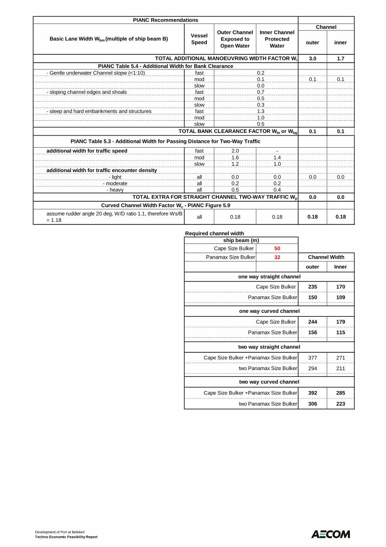
outer inner
PIANC Recommendations
Basic Lane Width Wbm (multiple of ship beam B) VesselSpeed
Outer ChannelExposed toOpen Water
Inner ChannelProtected
Water
Channel
3.0 1.7
- Gentle underwater Channel slopw (<1:10) fast 0.2mod 0.1 0.1 0.1slow 0.0
- sloping channel edges and shoals fast 0.7mod 0.5slow 0.3
- steep and hard embankments and structures fast 1.3mod 1.0slow 0.5
0.1 0.1
additional width for traffic speed fast 2.0 -mod 1.6 1.4slow 1.2 1.0
additional width for traffic encounter density- light all 0.0 0.0 0.0 0.0
- moderate all 0.2 0.2- heavy all 0.5 0.4
0.0 0.0
Cape Size Bulker 5032
outer Inner
235 170
150 109
244 179
156 115
377 271
294 211
392 285
306 223
TOTAL ADDITIONAL MANOEUVRING WIDTH FACTOR Wi
PIANC Table 5.4 - Additional Width for Bank Clearance
TOTAL BANK CLEARANCE FACTOR Wbr or Wbg
PIANC Table 5.3 - Additional Width for Passing Distance for Two-Way Traffic
TOTAL EXTRA FOR STRAIGHT CHANNEL TWO-WAY TRAFFIC Wp
Curved Channel Width Factor Wc - PIANC Figure 5.9assume rudder angle 20 deg, W/D ratio 1.1, therefore Ws/B= 1.18 all 0.18 0.18 0.18 0.18
Required channel widthship beam (m)
Panamax Size Bulker Channel Width
one way straight channel
Cape Size Bulker
Panamax Size Bulker
one way curved channel
Cape Size Bulker
two way curved channel
Cape Size Bulker +Panamax Size Bulker
two Panamax Size Bulker
Panamax Size Bulker
two way straight channel
Cape Size Bulker +Panamax Size Bulker
two Panamax Size Bulker
Development of Port at BelekeriTechno Economic Feasibility Report
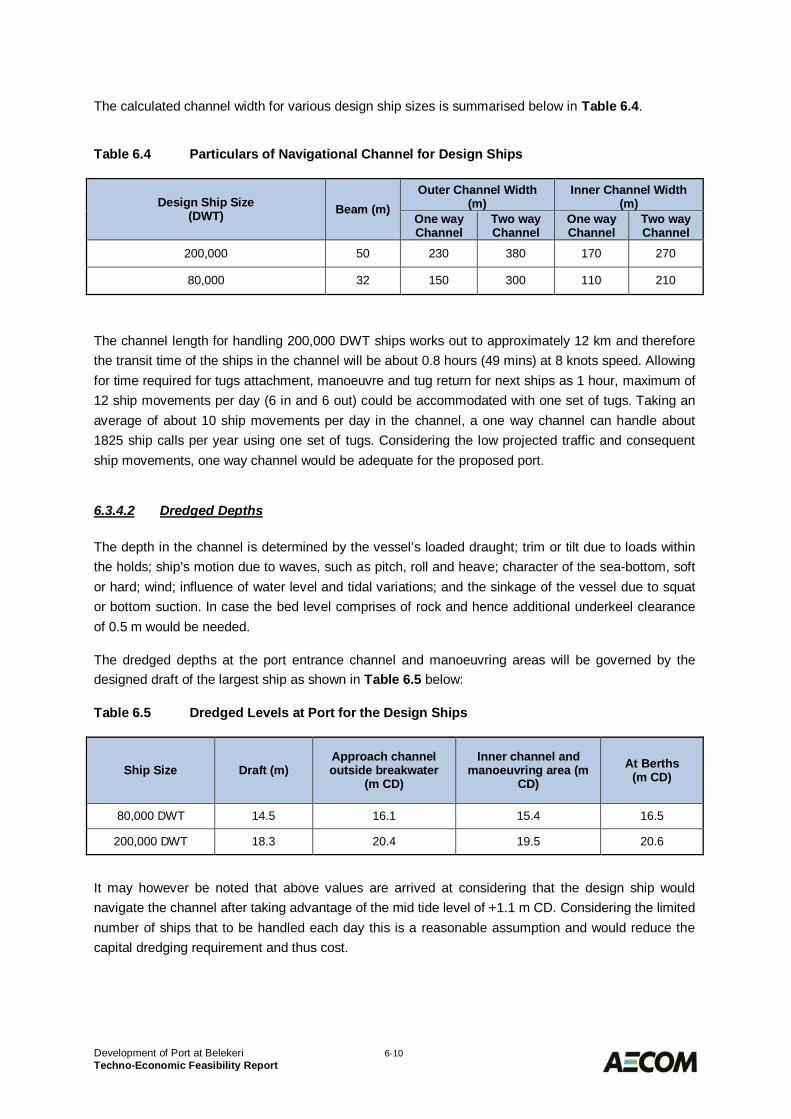
Development of Port at Belekeri 6-10Techno-Economic Feasibility Report
The calculated channel width for various design ship sizes is summarised below in Table 6.4.
Table 6.4 Particulars of Navigational Channel for Design Ships
Design Ship Size(DWT) Beam (m)
Outer Channel Width(m)
Inner Channel Width(m)
One wayChannel
Two wayChannel
One wayChannel
Two wayChannel
200,000 50 230 380 170 270
80,000 32 150 300 110 210
The channel length for handling 200,000 DWT ships works out to approximately 12 km and thereforethe transit time of the ships in the channel will be about 0.8 hours (49 mins) at 8 knots speed. Allowingfor time required for tugs attachment, manoeuvre and tug return for next ships as 1 hour, maximum of12 ship movements per day (6 in and 6 out) could be accommodated with one set of tugs. Taking anaverage of about 10 ship movements per day in the channel, a one way channel can handle about1825 ship calls per year using one set of tugs. Considering the low projected traffic and consequentship movements, one way channel would be adequate for the proposed port.
6.3.4.2 Dredged Depths
The depth in the channel is determined by the vessel’s loaded draught; trim or tilt due to loads withinthe holds; ship’s motion due to waves, such as pitch, roll and heave; character of the sea-bottom, softor hard; wind; influence of water level and tidal variations; and the sinkage of the vessel due to squator bottom suction. In case the bed level comprises of rock and hence additional underkeel clearanceof 0.5 m would be needed.
The dredged depths at the port entrance channel and manoeuvring areas will be governed by thedesigned draft of the largest ship as shown in Table 6.5 below:
Table 6.5 Dredged Levels at Port for the Design Ships
Ship Size Draft (m)Approach channeloutside breakwater
(m CD)
Inner channel andmanoeuvring area (m
CD)At Berths
(m CD)
80,000 DWT 14.5 16.1 15.4 16.5
200,000 DWT 18.3 20.4 19.5 20.6
It may however be noted that above values are arrived at considering that the design ship wouldnavigate the channel after taking advantage of the mid tide level of +1.1 m CD. Considering the limitednumber of ships that to be handled each day this is a reasonable assumption and would reduce thecapital dredging requirement and thus cost.
Development of Port at Belekeri 6-11Techno-Economic Feasibility Report
Elevations of Backup Area and Berths6.3.5
Considering the mean high water springs as +1.9 m CD and allowing for the operational wave heightof 1.0 m and thus crest height of 0.7 m and height of the structure as 1.5 m, the deck elevation ofberths is arrived at +5.0 m CD. This elevation would also protect the berth from slamming action ofwaves under cyclonic conditions. However, the finished levels of onshore areas will be kept at around+4.5 m CD.
Alternative Marine Layouts6.4Various alternative layouts for the development of Port at Belekeri have been prepared keeping inview various planning criteria as discussed above.
Alternative Layout 1 is a nearshore harbour option with most of the berths located close to the shore.This would result in shorter breakwater length but higher dredging quantities. The suitable materialobtained from dredging shall be used for reclamation and balance disposed offshore at a designatedlocation. The channel orientation at the harbour entrance is from NW direction but after a suitabledistance from harbour a bend is provided in the channel to reach deeper depths at a shortest possibledistance. The Phase 1 and master plan layouts of this alternative are as shown in DrawingDELD15005-DRG-10-0000-CP-BLR1001 and BLR1002.
Alternative Layout 2 involves offshore harbour option where the harbour area is located away fromthe shore. As compared to Alternative 1, the breakwaters in this alternative are longer but the amountof capital dredging is lower. The basic concept of developing this alternative is to minimise/ avoid therock dredging, which is likely to be encountered within the dredged depths considering the geology ofthe area. The channel orientation is similar to as that of Alternative 1. The Phase 1 and master planlayouts of this alternative are shown in Drawing DELD15005-DRG-10-0000-CP-BLR1003 andBLR1004.
Evaluation of the Alternative Port Layouts6.5
Cost Aspects6.5.1
One of the key considerations for the layouts evaluation is that it should be able to handle the projectthroughput in phased manner keeping the capital cost of development especially that of Phase 1development as optimum. It is to be noted that the items such as Berths and Equipment, Stackingareas, Internal Roads and Railway, Port Crafts, Nav-aids, Utilities, Buildings etc. are of negligible costdifference for all the alternative layouts. Therefore, for cost comparison for various alternative portlayouts, items of major cost difference need to be considered, as presented in Table 6.6 hereunder:
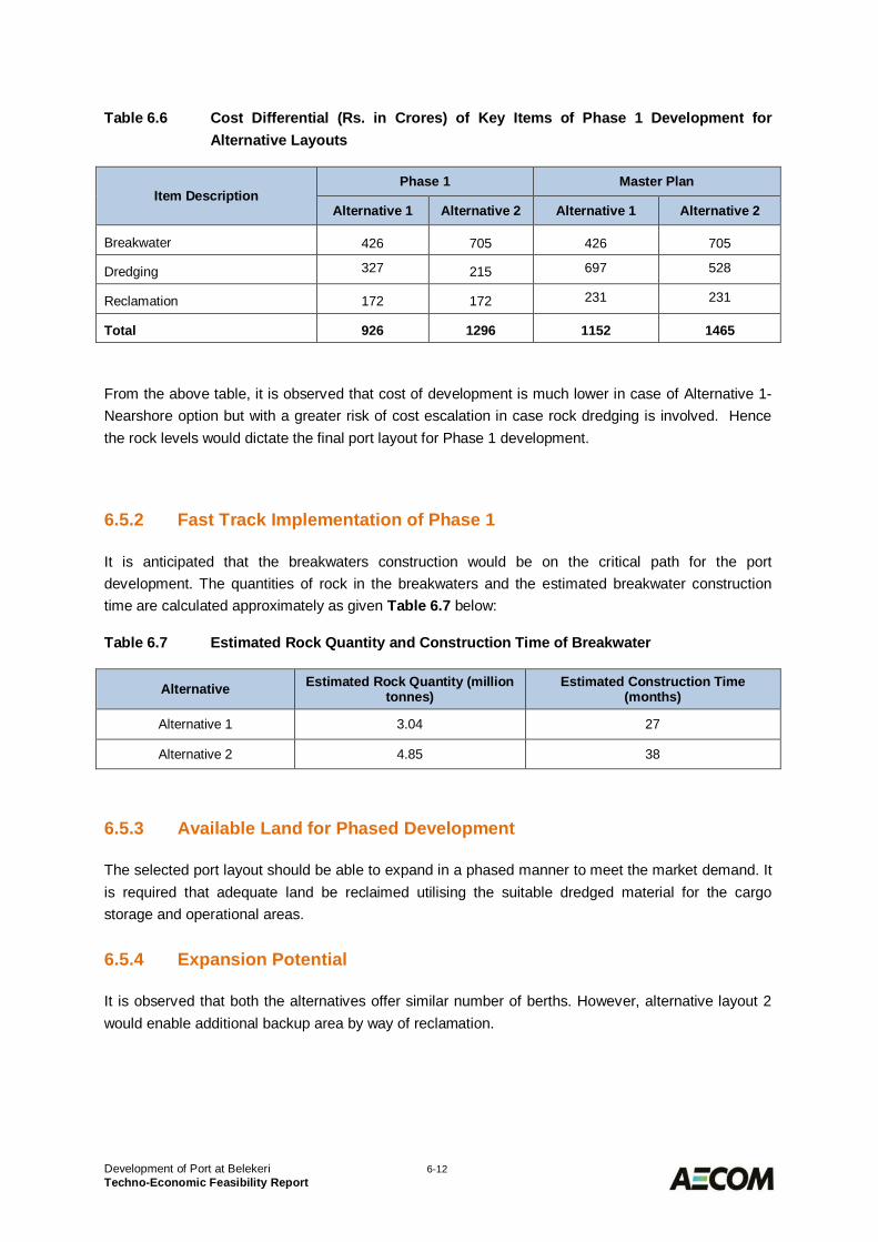
Development of Port at Belekeri 6-12Techno-Economic Feasibility Report
Table 6.6 Cost Differential (Rs. in Crores) of Key Items of Phase 1 Development forAlternative Layouts
Item DescriptionPhase 1 Master Plan
Alternative 1 Alternative 2 Alternative 1 Alternative 2
Breakwater 426 705 426 705
Dredging 327 215 697 528
Reclamation 172 172 231 231
Total 926 1296 1152 1465
From the above table, it is observed that cost of development is much lower in case of Alternative 1-Nearshore option but with a greater risk of cost escalation in case rock dredging is involved. Hencethe rock levels would dictate the final port layout for Phase 1 development.
Fast Track Implementation of Phase 16.5.2
It is anticipated that the breakwaters construction would be on the critical path for the portdevelopment. The quantities of rock in the breakwaters and the estimated breakwater constructiontime are calculated approximately as given Table 6.7 below:
Table 6.7 Estimated Rock Quantity and Construction Time of Breakwater
Alternative Estimated Rock Quantity (milliontonnes)
Estimated Construction Time(months)
Alternative 1 3.04 27
Alternative 2 4.85 38
Available Land for Phased Development6.5.3
The selected port layout should be able to expand in a phased manner to meet the market demand. Itis required that adequate land be reclaimed utilising the suitable dredged material for the cargostorage and operational areas.
Expansion Potential6.5.4
It is observed that both the alternatives offer similar number of berths. However, alternative layout 2would enable additional backup area by way of reclamation.
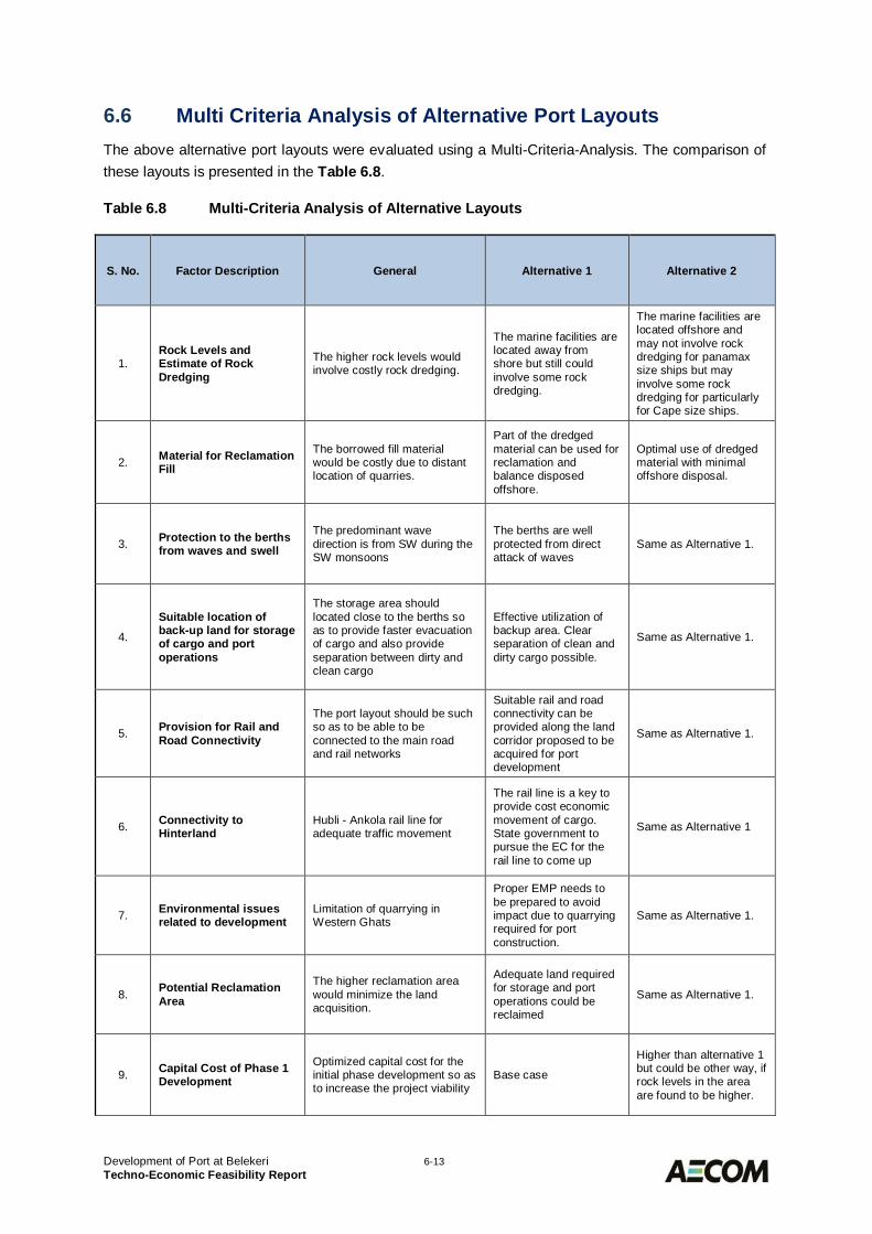
Development of Port at Belekeri 6-13Techno-Economic Feasibility Report
Multi Criteria Analysis of Alternative Port Layouts6.6The above alternative port layouts were evaluated using a Multi-Criteria-Analysis. The comparison ofthese layouts is presented in the Table 6.8.
Table 6.8 Multi-Criteria Analysis of Alternative Layouts
S. No. Factor Description General Alternative 1 Alternative 2
1.Rock Levels andEstimate of RockDredging
The higher rock levels wouldinvolve costly rock dredging.
The marine facilities arelocated away fromshore but still couldinvolve some rockdredging.
The marine facilities arelocated offshore andmay not involve rockdredging for panamaxsize ships but mayinvolve some rockdredging for particularlyfor Cape size ships.
2. Material for ReclamationFill
The borrowed fill materialwould be costly due to distantlocation of quarries.
Part of the dredgedmaterial can be used forreclamation andbalance disposedoffshore.
Optimal use of dredgedmaterial with minimaloffshore disposal.
3. Protection to the berthsfrom waves and swell
The predominant wavedirection is from SW during theSW monsoons
The berths are wellprotected from directattack of waves
Same as Alternative 1.
4.
Suitable location ofback-up land for storageof cargo and portoperations
The storage area shouldlocated close to the berths soas to provide faster evacuationof cargo and also provideseparation between dirty andclean cargo
Effective utilization ofbackup area. Clearseparation of clean anddirty cargo possible.
Same as Alternative 1.
5. Provision for Rail andRoad Connectivity
The port layout should be suchso as to be able to beconnected to the main roadand rail networks
Suitable rail and roadconnectivity can beprovided along the landcorridor proposed to beacquired for portdevelopment
Same as Alternative 1.
6. Connectivity toHinterland
Hubli - Ankola rail line foradequate traffic movement
The rail line is a key toprovide cost economicmovement of cargo.State government topursue the EC for therail line to come up
Same as Alternative 1
7. Environmental issuesrelated to development
Limitation of quarrying inWestern Ghats
Proper EMP needs tobe prepared to avoidimpact due to quarryingrequired for portconstruction.
Same as Alternative 1.
8. Potential ReclamationArea
The higher reclamation areawould minimize the landacquisition.
Adequate land requiredfor storage and portoperations could bereclaimed
Same as Alternative 1.
9. Capital Cost of Phase 1Development
Optimized capital cost for theinitial phase development so asto increase the project viability
Base case
Higher than alternative 1but could be other way, ifrock levels in the areaare found to be higher.
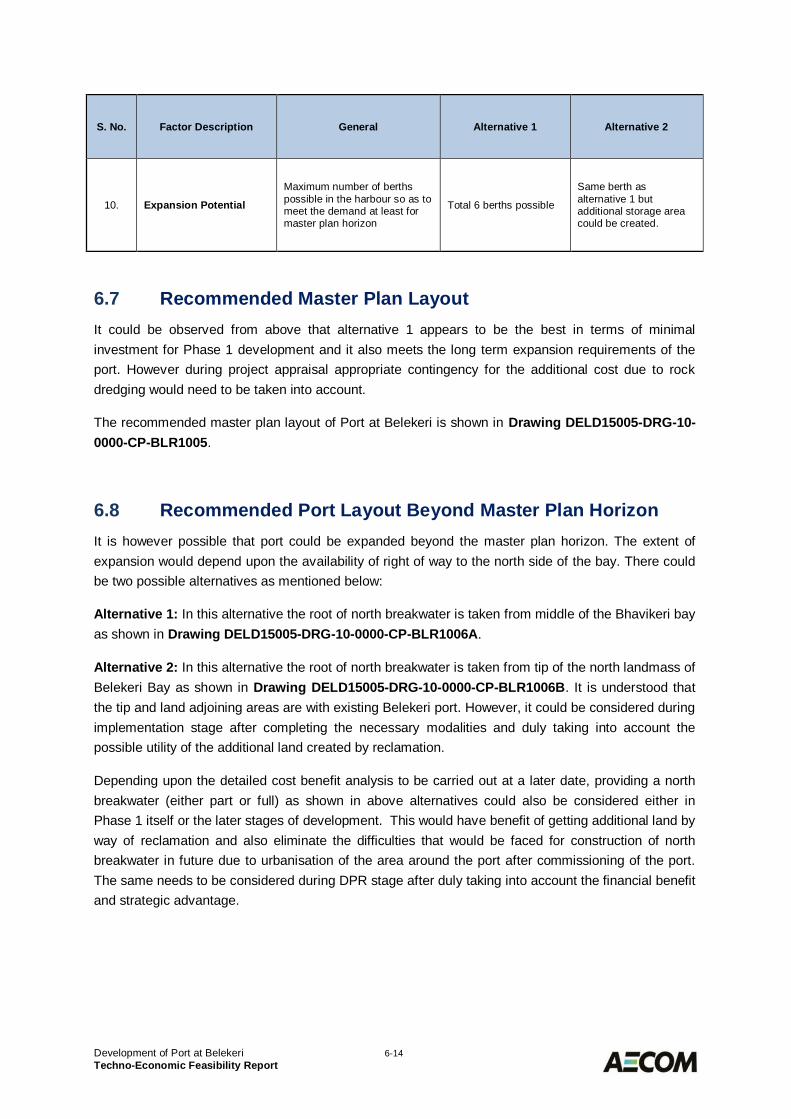
Development of Port at Belekeri 6-14Techno-Economic Feasibility Report
S. No. Factor Description General Alternative 1 Alternative 2
10. Expansion Potential
Maximum number of berthspossible in the harbour so as tomeet the demand at least formaster plan horizon
Total 6 berths possible
Same berth asalternative 1 butadditional storage areacould be created.
Recommended Master Plan Layout6.7It could be observed from above that alternative 1 appears to be the best in terms of minimalinvestment for Phase 1 development and it also meets the long term expansion requirements of theport. However during project appraisal appropriate contingency for the additional cost due to rockdredging would need to be taken into account.
The recommended master plan layout of Port at Belekeri is shown in Drawing DELD15005-DRG-10-0000-CP-BLR1005.
Recommended Port Layout Beyond Master Plan Horizon6.8It is however possible that port could be expanded beyond the master plan horizon. The extent ofexpansion would depend upon the availability of right of way to the north side of the bay. There couldbe two possible alternatives as mentioned below:
Alternative 1: In this alternative the root of north breakwater is taken from middle of the Bhavikeri bayas shown in Drawing DELD15005-DRG-10-0000-CP-BLR1006A.
Alternative 2: In this alternative the root of north breakwater is taken from tip of the north landmass ofBelekeri Bay as shown in Drawing DELD15005-DRG-10-0000-CP-BLR1006B. It is understood thatthe tip and land adjoining areas are with existing Belekeri port. However, it could be considered duringimplementation stage after completing the necessary modalities and duly taking into account thepossible utility of the additional land created by reclamation.
Depending upon the detailed cost benefit analysis to be carried out at a later date, providing a northbreakwater (either part or full) as shown in above alternatives could also be considered either inPhase 1 itself or the later stages of development. This would have benefit of getting additional land byway of reclamation and also eliminate the difficulties that would be faced for construction of northbreakwater in future due to urbanisation of the area around the port after commissioning of the port.The same needs to be considered during DPR stage after duly taking into account the financial benefitand strategic advantage.
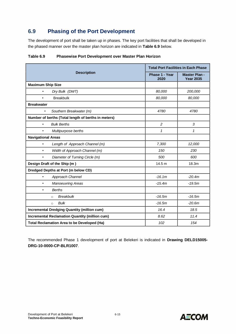
Development of Port at Belekeri 6-15Techno-Economic Feasibility Report
Phasing of the Port Development6.9The development of port shall be taken up in phases. The key port facilities that shall be developed inthe phased manner over the master plan horizon are indicated in Table 6.9 below.
Table 6.9 Phasewise Port Development over Master Plan Horizon
DescriptionTotal Port Facilities in Each Phase
Phase 1 - Year2020
Master Plan -Year 2035
Maximum Ship Size
· Dry Bulk (DWT) 80,000 200,000
· Breakbulk 80,000 80,000
Breakwater
· Southern Breakwater (m) 4780 4780
Number of berths (Total length of berths in meters)
· Bulk Berths 2 3
· Multipurpose berths 1 1
Navigational Areas
· Length of Approach Channel (m) 7,300 12,000
· Width of Approach Channel (m) 150 230
· Diameter of Turning Circle (m) 500 600
Design Draft of the Ship (m ) 14.5 m 18.3m
Dredged Depths at Port (m below CD)
· Approach Channel -16.1m -20.4m
· Manoeuvring Areas -15.4m -19.5m
· Berths
o Breakbulk -16.5m -16.5m
o Bulk -16.5m -20.6m
Incremental Dredging Quantity (million cum) 16.4 18.5
Incremental Reclamation Quantity (million cum) 8.62 11.4
Total Reclamation Area to be Developed (Ha) 102 154
The recommended Phase 1 development of port at Belekeri is indicated in Drawing DELD15005-DRG-10-0000-CP-BLR1007.
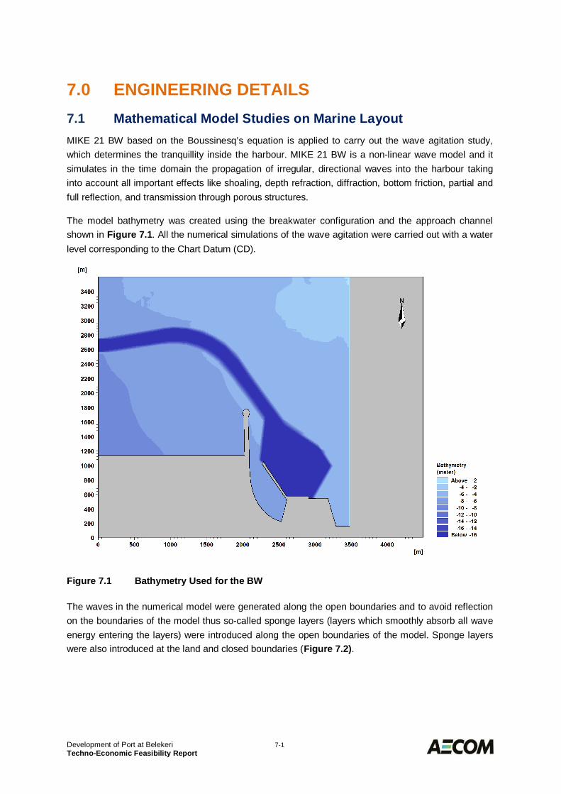
Development of Port at Belekeri 7-1Techno-Economic Feasibility Report
ENGINEERING DETAILS7.0Mathematical Model Studies on Marine Layout7.1
MIKE 21 BW based on the Boussinesq’s equation is applied to carry out the wave agitation study,which determines the tranquillity inside the harbour. MIKE 21 BW is a non-linear wave model and itsimulates in the time domain the propagation of irregular, directional waves into the harbour takinginto account all important effects like shoaling, depth refraction, diffraction, bottom friction, partial andfull reflection, and transmission through porous structures.
The model bathymetry was created using the breakwater configuration and the approach channelshown in Figure 7.1. All the numerical simulations of the wave agitation were carried out with a waterlevel corresponding to the Chart Datum (CD).
Figure 7.1 Bathymetry Used for the BW
The waves in the numerical model were generated along the open boundaries and to avoid reflectionon the boundaries of the model thus so-called sponge layers (layers which smoothly absorb all waveenergy entering the layers) were introduced along the open boundaries of the model. Sponge layerswere also introduced at the land and closed boundaries (Figure 7.2).
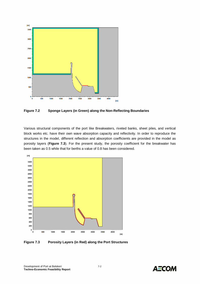
Development of Port at Belekeri 7-2Techno-Economic Feasibility Report
Figure 7.2 Sponge Layers (in Green) along the Non-Reflecting Boundaries
Various structural components of the port like Breakwaters, riveted banks, sheet piles, and verticalblock works etc. have their own wave absorption capacity and reflectivity. In order to reproduce thestructures in the model, different reflection and absorption coefficients are provided in the model asporosity layers (Figure 7.3). For the present study, the porosity coefficient for the breakwater hasbeen taken as 0.5 while that for berths a value of 0.8 has been considered.
Figure 7.3 Porosity Layers (in Red) along the Port Structures
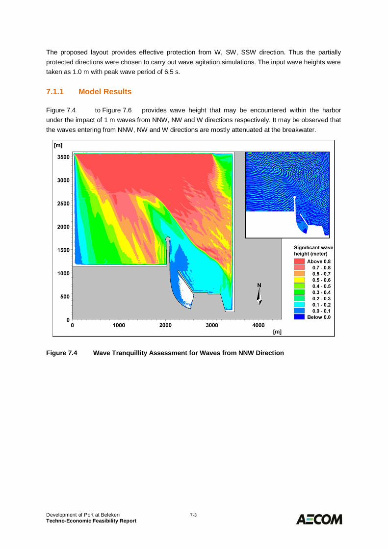
Development of Port at Belekeri 7-3Techno-Economic Feasibility Report
The proposed layout provides effective protection from W, SW, SSW direction. Thus the partiallyprotected directions were chosen to carry out wave agitation simulations. The input wave heights weretaken as 1.0 m with peak wave period of 6.5 s.
Model Results7.1.1
Figure 7.4 to Figure 7.6 provides wave height that may be encountered within the harborunder the impact of 1 m waves from NNW, NW and W directions respectively. It may be observed thatthe waves entering from NNW, NW and W directions are mostly attenuated at the breakwater.
Figure 7.4 Wave Tranquillity Assessment for Waves from NNW Direction
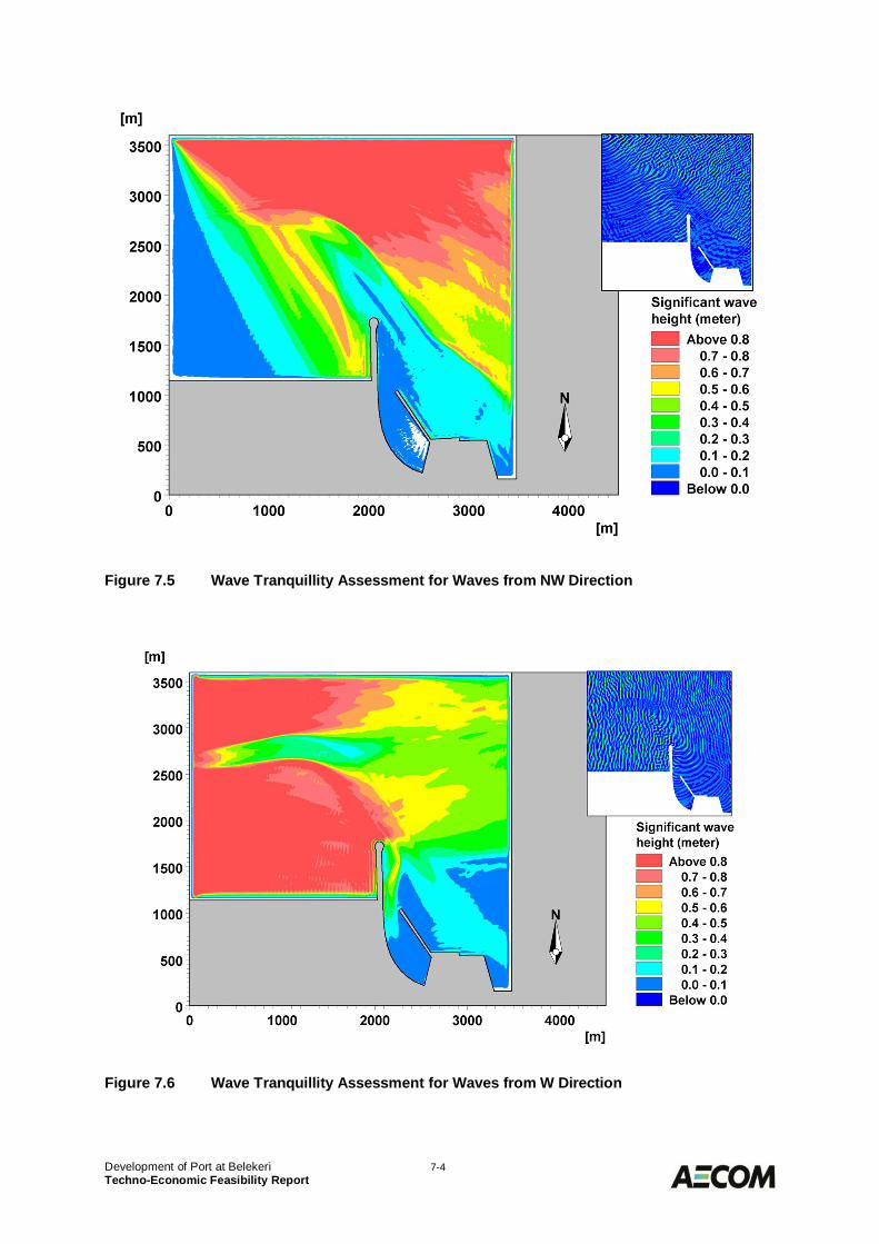
Development of Port at Belekeri 7-4Techno-Economic Feasibility Report
Figure 7.5 Wave Tranquillity Assessment for Waves from NW Direction
Figure 7.6 Wave Tranquillity Assessment for Waves from W Direction
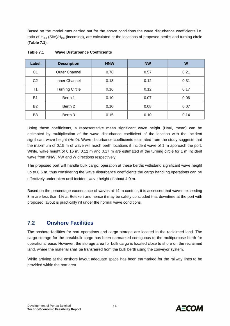
Development of Port at Belekeri 7-5Techno-Economic Feasibility Report
Based on the model runs carried out for the above conditions the wave disturbance coefficients i.e.ratio of Hmo (Site)/Hmo (incoming), are calculated at the locations of proposed berths and turning circle(Table 7.1).
Table 7.1 Wave Disturbance Coefficients
Label Description NNW NW W
C1 Outer Channel 0.78 0.57 0.21
C2 Inner Channel 0.18 0.12 0.31
T1 Turning Circle 0.16 0.12 0.17
B1 Berth 1 0.10 0.07 0.06
B2 Berth 2 0.10 0.08 0.07
B3 Berth 3 0.15 0.10 0.14
Using these coefficients, a representative mean significant wave height (Hm0, mean) can beestimated by multiplication of the wave disturbance coefficient of the location with the incidentsignificant wave height (Hm0). Wave disturbance coefficients estimated from the study suggests thatthe maximum of 0.15 m of wave will reach berth locations if incident wave of 1 m approach the port.While, wave height of 0.16 m, 0.12 m and 0.17 m are estimated at the turning circle for 1 m incidentwave from NNW, NW and W directions respectively.
The proposed port will handle bulk cargo, operation at these berths withstand significant wave height
up to 0.6 m. thus considering the wave disturbance coefficients the cargo handling operations can be
effectively undertaken until incident wave height of about 4.0 m.
Based on the percentage exceedance of waves at 14 m contour, it is assessed that waves exceeding3 m are less than 1% at Belekeri and hence it may be safely concluded that downtime at the port withproposed layout is practically nil under the normal wave conditions.
Onshore Facilities7.2The onshore facilities for port operations and cargo storage are located in the reclaimed land. Thecargo storage for the breakbulk cargo has been earmarked contiguous to the multipurpose berth foroperational ease. However, the storage area for bulk cargo is located close to shore on the reclaimedland, where the material shall be transferred from the bulk berth using the conveyor system.
While arriving at the onshore layout adequate space has been earmarked for the railway lines to beprovided within the port area.
Development of Port at Belekeri 7-6Techno-Economic Feasibility Report
Breakwaters7.3
Basic Data for Breakwaters Design7.3.1
7.3.1.1 Design Wave Height
The wave heights to be considered for the breakwaters design would depend upon the extreme waveconditions for 1 in 10 years and 1 in 50 year return periods for the respective depths in whichbreakwaters are located from considerations of over topping and section design respectively.
Based on the available data in the region having similar water depths upto which the breakwaterextends, the design wave height adopted is 5.5 m for the head and truck sections located in deeperwaters. For sections closer to shore the design wave height shall be governed by correspondingbreaking wave height in that water depth, whichever is critical.
7.3.1.2 Design Assumptions
· Stones upto 5.0 T are economically available with density of 2.6 T/m3
· The minimum density of concrete armour units will be 2.4 T/m3
· Concrete slab with a parapet will be provided at the crest of the breakwater· The design life of the breakwater is 100 years.· The breakwater construction will be by end-on dumping method and that there will be no
restriction/ limitations of crane for laying armour units. However where ever possibleconstruction shall by carried out by Barge dumping also.
7.3.1.3 Crest Width and Elevation
The primary purpose of the breakwaters at the port is to provide the required tranquillity conditions inthe manoeuvring areas and berths. The required minimum crest height of the breakwater isdetermined by the allowable wave penetration by overtopping during extreme conditions.
The crest level has been decided based on the limiting the overtopping discharge to 50 l/s/m. Thecrest width is determined after allowing a 2 way roadway for the maintenance of breakwater.
7.3.1.4 Armour Units
For the armour units following options have been considered:
· Rock as armour layer· Accropodes as Concrete Armour Units
While evaluating the above options the major factor under consideration will be the cost ofbreakwaters and the implementation schedule. It is expected that at the present site conditions, theplacement of rock for breakwater construction, will be limited on an average to about 7,000 T/day byend on dumping method including the quantity of rock that could be placed by using the bargedumping also.
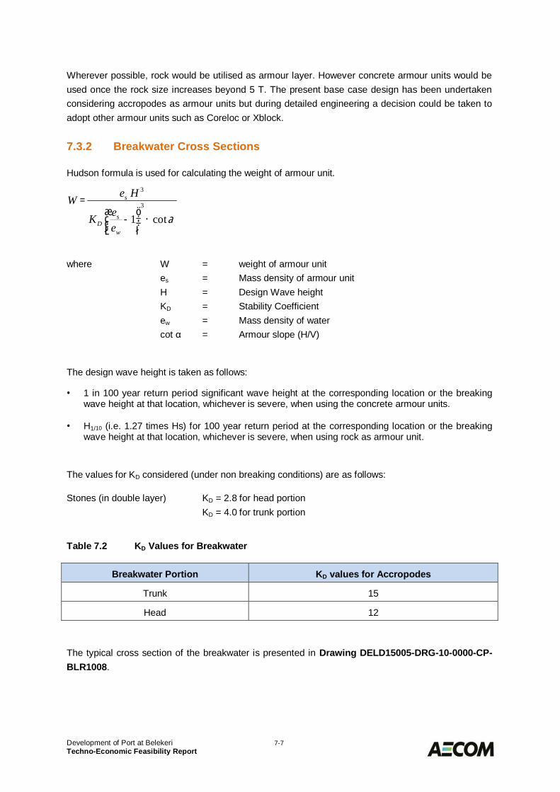
Development of Port at Belekeri 7-7Techno-Economic Feasibility Report
Wherever possible, rock would be utilised as armour layer. However concrete armour units would beused once the rock size increases beyond 5 T. The present base case design has been undertakenconsidering accropodes as armour units but during detailed engineering a decision could be taken toadopt other armour units such as Coreloc or Xblock.
Breakwater Cross Sections7.3.2
Hudson formula is used for calculating the weight of armour unit.
where W = weight of armour unites = Mass density of armour unitH = Design Wave heightKD = Stability Coefficientew = Mass density of watercot α = Armour slope (H/V)
The design wave height is taken as follows:
· 1 in 100 year return period significant wave height at the corresponding location or the breakingwave height at that location, whichever is severe, when using the concrete armour units.
· H1/10 (i.e. 1.27 times Hs) for 100 year return period at the corresponding location or the breakingwave height at that location, whichever is severe, when using rock as armour unit.
The values for KD considered (under non breaking conditions) are as follows:
Stones (in double layer) KD = 2.8 for head portionKD = 4.0 for trunk portion
Table 7.2 KD Values for Breakwater
Breakwater Portion KD values for Accropodes
Trunk 15
Head 12
The typical cross section of the breakwater is presented in Drawing DELD15005-DRG-10-0000-CP-BLR1008.
acot13
3
´÷÷ø
öççè
æ-
=
w
sD
s
eeK
HeW
Development of Port at Belekeri 7-8Techno-Economic Feasibility Report
Geotechnical Assessment of Breakwaters7.3.3
The seabed level at the breakwaters increases from +2.0 m CD near the shore to a maximum of –7.0m CD. The crest level of breakwater is assumed at the maximum depth is about +8.5 m CD.
The stability of the breakwater foundation needs to be analysed for the subsoil conditions at thelocations. In the present case the breakwaters are likely to be on a good founding strata overlayingrock.
Rock Quarrying and Transportation7.3.4
7.3.4.1 Location of Quarries
It is understood during the site visit, the the environmental ministry has imposed ban on rock quarryingdue to the sensitivity of the western ghats. The rock for the construction of breakwater works need tosourced out from the government approved quarries in the area.
7.3.4.2 Transport to Site
The quarry material will have to be transported in through dumpers. Some localise road improvementmeasures will need to be undertaken near the quarries and near the project site to enable moving ofthe large quantity of stones by road using trucks.
Berthing Facilities7.4
Location and Orientation7.4.1
The location and orientation of the proposed berths is shown Drawing DELD15005-DRG-10-0000-CP-BLR1007. Ideally the Container / Multipurpose berths should be built contiguous to the land forease of handling operations, whereas the bulk berths could be located away and connected to shoreby means of an approach trestle. Considering the high dredging requirement at the berth locations, itis proposed to provide the bulk and multipurpose berth away from the shore and some portion ofbackup area is created behind multipurpose berth for transit storing and backup area near the shoreto which the connection shall be by approach bund/trestle.
Deck Elevation7.4.2
The deck elevation of the berths has been fixed at +5.0 m CD. This deck elevation will prevent thewaves slamming the deck during cyclones. This deck level will also ensure adequate clearance to thedeck during operational wave conditions.
Development of Port at Belekeri 7-9Techno-Economic Feasibility Report
Design Criteria7.4.3
The structural design of the bulk and multipurpose berths shall be carried out for the maximum size ofthe ships expected to be handled at these berths at the ultimate phase. The details of design shipsizes are given in Table 7.3 below:
Table 7.3 Characteristics of Design Ships
Commodity Design Ship Size (DWT)
Coal 200,000
Multipurpose 80,000
Containers 4,000 TEUs
7.4.3.1 Design Dredged Level
Structural design of the berths shall be carried out for design dredged level of -21 m CD.
7.4.3.2 Design Loads
· Dead Loads comprising the self-weight of the structure plus superimposed loads of permanentnature shall be considered as per IS: 875 (Part-I) 1987.
· Live Load on the deck slab shall be 5 T/m2
· Vehicle and Crane Loads as per details below:o Loads due to Gantry type unloaders with rail centres at 20 m c/c on bulk bertho Mobile Harbour Cranes LMH500 or equivalent on Multipurpose bertho Single train of IRC class AA vehicle or Loads due to mobile crane of 70 T lifting capacity
· Seismic Loads on the structures shall be computed in accordance with the seismic code of IndiaIS: 1893.
· Wind Loads on the structures shall be calculated using a basic wind speed of 40 m/s as per theIndian standards. However, wind speed during the operational conditions shall be limited to 20m/s only.
· Current Loads on the structure shall be applied on the submerged parts of the structureconsidering the maximum current velocity as 1.0 m/s.
· Wave Loads shall be computed considering maximum wave height of 4.5 m (~ 1.8*2.5m) for thedesign of the berths on a conservative side.
· Mooring Loads shall be calculated considering 200 T bollard pull.
· Berthing Loads
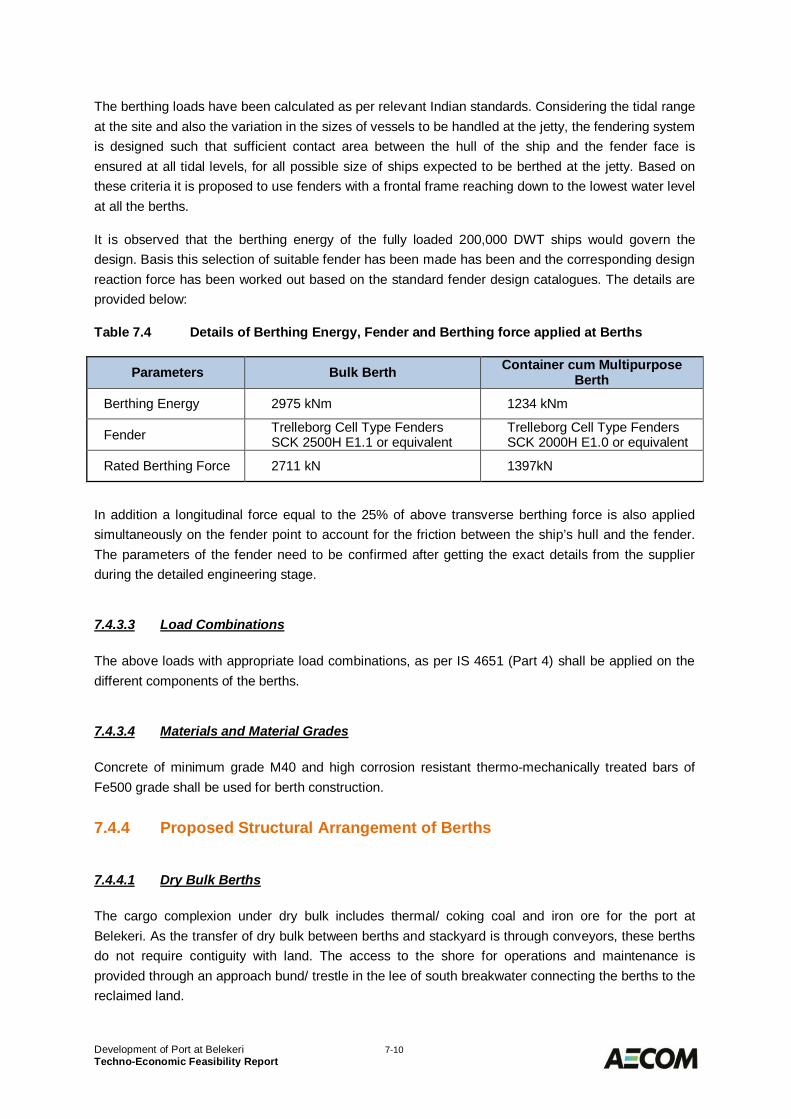
Development of Port at Belekeri 7-10Techno-Economic Feasibility Report
The berthing loads have been calculated as per relevant Indian standards. Considering the tidal rangeat the site and also the variation in the sizes of vessels to be handled at the jetty, the fendering systemis designed such that sufficient contact area between the hull of the ship and the fender face isensured at all tidal levels, for all possible size of ships expected to be berthed at the jetty. Based onthese criteria it is proposed to use fenders with a frontal frame reaching down to the lowest water levelat all the berths.
It is observed that the berthing energy of the fully loaded 200,000 DWT ships would govern thedesign. Basis this selection of suitable fender has been made has been and the corresponding designreaction force has been worked out based on the standard fender design catalogues. The details areprovided below:
Table 7.4 Details of Berthing Energy, Fender and Berthing force applied at Berths
Parameters Bulk Berth Container cum MultipurposeBerth
Berthing Energy 2975 kNm 1234 kNm
Fender Trelleborg Cell Type FendersSCK 2500H E1.1 or equivalent
Trelleborg Cell Type FendersSCK 2000H E1.0 or equivalent
Rated Berthing Force 2711 kN 1397kN
In addition a longitudinal force equal to the 25% of above transverse berthing force is also appliedsimultaneously on the fender point to account for the friction between the ship’s hull and the fender.The parameters of the fender need to be confirmed after getting the exact details from the supplierduring the detailed engineering stage.
7.4.3.3 Load Combinations
The above loads with appropriate load combinations, as per IS 4651 (Part 4) shall be applied on thedifferent components of the berths.
7.4.3.4 Materials and Material Grades
Concrete of minimum grade M40 and high corrosion resistant thermo-mechanically treated bars ofFe500 grade shall be used for berth construction.
Proposed Structural Arrangement of Berths7.4.4
7.4.4.1 Dry Bulk Berths
The cargo complexion under dry bulk includes thermal/ coking coal and iron ore for the port atBelekeri. As the transfer of dry bulk between berths and stackyard is through conveyors, these berthsdo not require contiguity with land. The access to the shore for operations and maintenance isprovided through an approach bund/ trestle in the lee of south breakwater connecting the berths to thereclaimed land.
Development of Port at Belekeri 7-11Techno-Economic Feasibility Report
A common system is proposed to handle thermal coal, coking coal and iron ore at 2 bulk berths. Theberths shall be provided with a conveyor system which will carry the dry bulk from the berth andtransfer to the conveyor provided over the approach bund/ trestle.
The minimum width of the berth, keeping in view the rail span of the coal unloaders, service ducts andthe end clearances should be about 30m. The total length of each dry bulk berth is taken as 300m.
In view of the above arrangement of berth and its location, founding strata, piled foundation isconsidered as best option for the structural system. The proposed structural scheme consists of fourrows of vertical bored cast-in-situ RCC piles of 1.2 m diameter, spaced at 8.0 m c/c in the longitudinaldirection. The piles will be founded in substrata at levels beyond -40 m CD.
In the transverse direction, main beams are provided supported over the piles, which in turn supportbeams in the longitudinal direction. The longitudinal beams, at the front row and the fourth row, aredesigned for loads due to ship unloaders. A 300 mm thick deck slab will be provided supported overthe intermediate longitudinal beams.
Bollards and rubber fenders will be provided @ 24 m c/c along the berthing face. A service trench willbe provided on the berthing side to accommodate cables/utilities. The conveyor supports are providedin the rear side of the berth at a spacing not exceeding 24 m. The typical cross section of bulk berth isas shown in Drawing DELD15005-DRG-10-0000-CP-BLR1009.
7.4.4.2 Container cum Multipurpose Berths
The container cum multipurpose berth is connected to land by means of approach trestle. Due to therequirement of placing the ship’s hatch covers additional area has been created by reclaiming the landbehind the berth and hence the width of the berth is taken same as that of bulk berth i.e. 30 m.
The structural arrangement of the berth is based on the design criteria. The proposed schemeconsists of four rows of vertical bored cast-in-situ RCC piles of 1.2 m diameter, spaced at 8.0 m c/c inthe longitudinal direction. The piles will be founded in subsea strata at levels beyond -40 m CD.
In the transverse direction, main beams are provided supported over the piles, which in turn supportbeams in the longitudinal direction. The longitudinal beams, at the front row and the third row, aredesigned for crane loads. A 500 mm thick deck slab will be provided supported over the intermediatelongitudinal beams.
Bollards and rubber fenders will be provided @ 24 m c/c along the berthing face. A service trench willbe provided on the berthing side to accommodate cables/utilities.
The berth is connected to the shore by means of 980 m long and 15 m wide approach bund to backup area. The approach shall be either in the form of bund or a trestle supported over three rows of 1.1m diameter bored cast in situ piles. The typical cross section of bulk berth is as shown in DrawingDELD15005-DRG-10-0000-CP-BLR1010.
Development of Port at Belekeri 7-12Techno-Economic Feasibility Report
Dredging and Disposal7.5
Capital Dredging7.5.1
The capital dredging for Phase 1 of the port development is estimated to be around 16.4 million cumrequired for handling panamax size ships. Nearly half of the dredged material shall be used forreclamation and balance shall be disposed off at a suitable location offshore at about 30 m contour.
Maintenance Dredging7.5.2
As the harbour area is located in deeper waters and there is no river estuary nearby bringing in largesediments. Therefore the annual maintenance dredging volumes are expected to be very low andlimited to about 700,000 cum per annum only including the littoral drift material that could find way tothe channel.
Reclamation7.6
Areas to be Reclaimed7.6.1
It is proposed that the area behind the bulk and container cum multipurpose berths shall be reclaimedto provide the space for transit storage and area along the shore line to create the backup area forstorage and operation. The reclamation level is proposed to be +4.5 m CD and the total quantity ofreclamation fill is estimated as 8.6 Mcum which can be carried out through suitable material fromcapital dredging.
The reclamation process comprise of creating bunds in the reclamation areas of suitable heights toreceive the dredged material. Considering that most of the fill will be placed under water, the bundswill need to be formed of Rock/ boulders. Thereafter the reclamation levels within the bunds are raisedin suitable stages, to prevent overloading of the underlying subsoil. Placement of the reclamation fillwill be mostly Sub-aqueous i.e. in the water body, considering that the tidal levels in the area varybetween +0 to +1.9 m CD. Between the elevations + 2 to +5 m, the placement will be sub-aerial, i.e. inthe air. The reclamation sequence should be such that there is no accumulation of silt/clay at oneplace. The fill material shall be placed in layers with height of each layer limited to 2 m.
Material Handling System7.7
7.7.1 Bulk Import System
7.7.1.1 General System Description
A fully mechanized common ship unloading system is planned at the bulk berths to handle thermal/coking coal and iron ore. The system is designed for a rated capacity of 4,000 TPH to ensure fasterturnaround of vessels at berth.
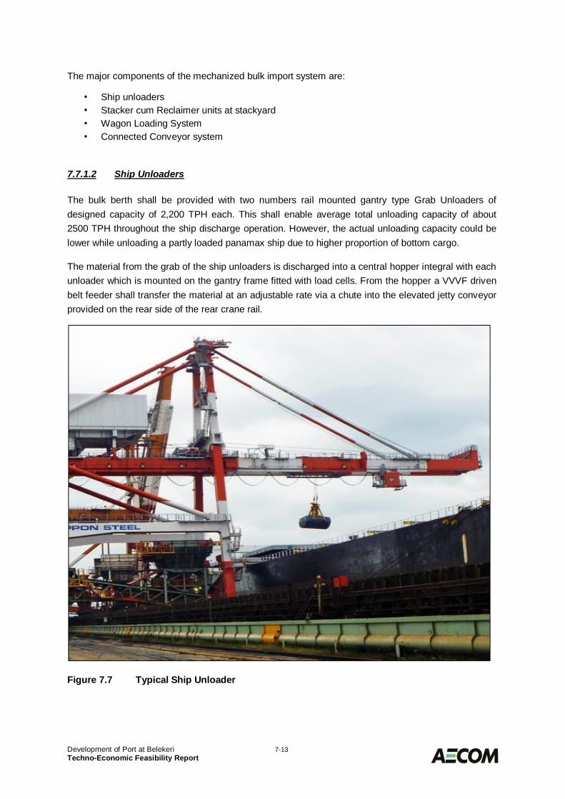
Development of Port at Belekeri 7-13Techno-Economic Feasibility Report
The major components of the mechanized bulk import system are:
· Ship unloaders· Stacker cum Reclaimer units at stackyard· Wagon Loading System· Connected Conveyor system
7.7.1.2 Ship Unloaders
The bulk berth shall be provided with two numbers rail mounted gantry type Grab Unloaders ofdesigned capacity of 2,200 TPH each. This shall enable average total unloading capacity of about2500 TPH throughout the ship discharge operation. However, the actual unloading capacity could belower while unloading a partly loaded panamax ship due to higher proportion of bottom cargo.
The material from the grab of the ship unloaders is discharged into a central hopper integral with eachunloader which is mounted on the gantry frame fitted with load cells. From the hopper a VVVF drivenbelt feeder shall transfer the material at an adjustable rate via a chute into the elevated jetty conveyorprovided on the rear side of the rear crane rail.
Figure 7.7 Typical Ship Unloader
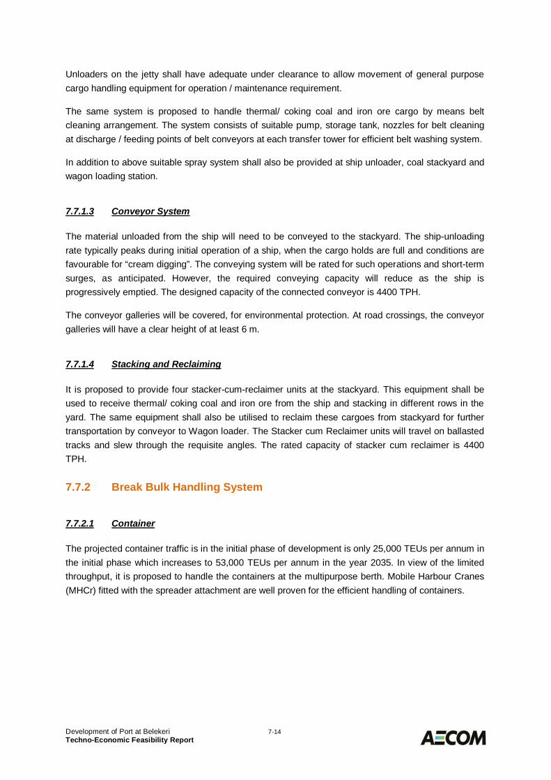
Development of Port at Belekeri 7-14Techno-Economic Feasibility Report
Unloaders on the jetty shall have adequate under clearance to allow movement of general purposecargo handling equipment for operation / maintenance requirement.
The same system is proposed to handle thermal/ coking coal and iron ore cargo by means beltcleaning arrangement. The system consists of suitable pump, storage tank, nozzles for belt cleaningat discharge / feeding points of belt conveyors at each transfer tower for efficient belt washing system.
In addition to above suitable spray system shall also be provided at ship unloader, coal stackyard andwagon loading station.
7.7.1.3 Conveyor System
The material unloaded from the ship will need to be conveyed to the stackyard. The ship-unloadingrate typically peaks during initial operation of a ship, when the cargo holds are full and conditions arefavourable for “cream digging”. The conveying system will be rated for such operations and short-termsurges, as anticipated. However, the required conveying capacity will reduce as the ship isprogressively emptied. The designed capacity of the connected conveyor is 4400 TPH.
The conveyor galleries will be covered, for environmental protection. At road crossings, the conveyorgalleries will have a clear height of at least 6 m.
7.7.1.4 Stacking and Reclaiming
It is proposed to provide four stacker-cum-reclaimer units at the stackyard. This equipment shall beused to receive thermal/ coking coal and iron ore from the ship and stacking in different rows in theyard. The same equipment shall also be utilised to reclaim these cargoes from stackyard for furthertransportation by conveyor to Wagon loader. The Stacker cum Reclaimer units will travel on ballastedtracks and slew through the requisite angles. The rated capacity of stacker cum reclaimer is 4400TPH.
Break Bulk Handling System7.7.2
7.7.2.1 Container
The projected container traffic is in the initial phase of development is only 25,000 TEUs per annum inthe initial phase which increases to 53,000 TEUs per annum in the year 2035. In view of the limitedthroughput, it is proposed to handle the containers at the multipurpose berth. Mobile Harbour Cranes(MHCr) fitted with the spreader attachment are well proven for the efficient handling of containers.
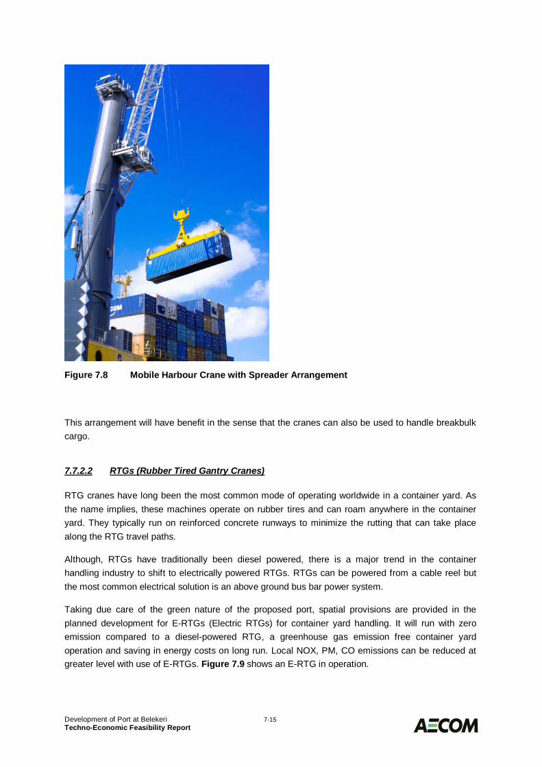
Development of Port at Belekeri 7-15Techno-Economic Feasibility Report
Figure 7.8 Mobile Harbour Crane with Spreader Arrangement
This arrangement will have benefit in the sense that the cranes can also be used to handle breakbulkcargo.
7.7.2.2 RTGs (Rubber Tired Gantry Cranes)
RTG cranes have long been the most common mode of operating worldwide in a container yard. Asthe name implies, these machines operate on rubber tires and can roam anywhere in the containeryard. They typically run on reinforced concrete runways to minimize the rutting that can take placealong the RTG travel paths.
Although, RTGs have traditionally been diesel powered, there is a major trend in the containerhandling industry to shift to electrically powered RTGs. RTGs can be powered from a cable reel butthe most common electrical solution is an above ground bus bar power system.
Taking due care of the green nature of the proposed port, spatial provisions are provided in theplanned development for E-RTGs (Electric RTGs) for container yard handling. It will run with zeroemission compared to a diesel-powered RTG, a greenhouse gas emission free container yardoperation and saving in energy costs on long run. Local NOX, PM, CO emissions can be reduced atgreater level with use of E-RTGs. Figure 7.9 shows an E-RTG in operation.
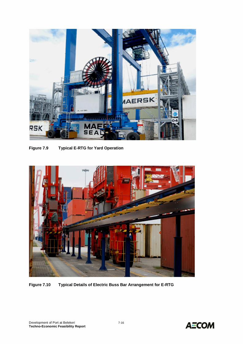
Development of Port at Belekeri 7-16Techno-Economic Feasibility Report
Figure 7.9 Typical E-RTG for Yard Operation
Figure 7.10 Typical Details of Electric Buss Bar Arrangement for E-RTG
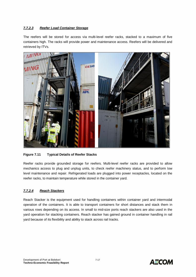
Development of Port at Belekeri 7-17Techno-Economic Feasibility Report
7.7.2.3 Reefer Load Container Storage
The reefers will be stored for access via multi-level reefer racks, stacked to a maximum of fivecontainers high. The racks will provide power and maintenance access. Reefers will be delivered andretrieved by ITVs.
Figure 7.11 Typical Details of Reefer Stacks
Reefer racks provide grounded storage for reefers. Multi-level reefer racks are provided to allowmechanics access to plug and unplug units, to check reefer machinery status, and to perform lowlevel maintenance and repair. Refrigerated loads are plugged into power receptacles, located on thereefer racks, to maintain temperature while stored in the container yard.
7.7.2.4 Reach Stackers
Reach Stacker is the equipment used for handling containers within container yard and intermodaloperation of the containers. It is able to transport containers for short distances and stack them invarious rows depending on its access. In small to mid-size ports reach stackers are also used in theyard operation for stacking containers. Reach stacker has gained ground in container handling in railyard because of its flexibility and ability to stack across rail tracks.
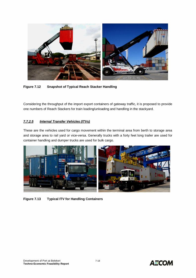
Development of Port at Belekeri 7-18Techno-Economic Feasibility Report
Figure 7.12 Snapshot of Typical Reach Stacker Handling
Considering the throughput of the import export containers of gateway traffic, it is proposed to provideone numbers of Reach Stackers for train loading/unloading and handling in the stackyard.
7.7.2.5 Internal Transfer Vehicles (ITVs)
These are the vehicles used for cargo movement within the terminal area from berth to storage areaand storage area to rail yard or vice-versa. Generally trucks with a forty feet long trailer are used forcontainer handling and dumper trucks are used for bulk cargo.
Figure 7.13 Typical ITV for Handling Containers
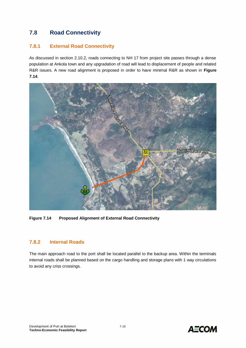
Development of Port at Belekeri 7-19Techno-Economic Feasibility Report
Road Connectivity7.8
External Road Connectivity7.8.1
As discussed in section 2.10.2, roads connecting to NH 17 from project site passes through a densepopulation at Ankola town and any upgradation of road will lead to displacement of people and relatedR&R issues. A new road alignment is proposed in order to have minimal R&R as shown in Figure7.14.
Figure 7.14 Proposed Alignment of External Road Connectivity
Internal Roads7.8.2
The main approach road to the port shall be located parallel to the backup area. Within the terminalsinternal roads shall be planned based on the cargo handling and storage plans with 1 way circulationsto avoid any criss crossings.
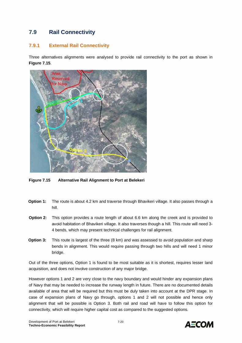
Development of Port at Belekeri 7-20Techno-Economic Feasibility Report
Rail Connectivity7.9
External Rail Connectivity7.9.1
Three alternatives alignments were analysed to provide rail connectivity to the port as shown inFigure 7.15.
Figure 7.15 Alternative Rail Alignment to Port at Belekeri
Option 1: The route is about 4.2 km and traverse through Bhavikeri village. It also passes through ahill.
Option 2: This option provides a route length of about 6.6 km along the creek and is provided toavoid habitation of Bhavikeri village. It also traverses though a hill. This route will need 3-4 bends, which may present technical challenges for rail alignment.
Option 3: This route is largest of the three (8 km) and was assessed to avoid population and sharpbends in alignment. This would require passing through two hills and will need 1 minorbridge.
Out of the three options, Option 1 is found to be most suitable as it is shortest, requires lesser landacquisition, and does not involve construction of any major bridge.
However options 1 and 2 are very close to the navy boundary and would hinder any expansion plansof Navy that may be needed to increase the runway length in future. There are no documented detailsavailable of area that will be required but this must be duly taken into account at the DPR stage. Incase of expansion plans of Navy go through, options 1 and 2 will not possible and hence onlyalignment that will be possible is Option 3. Both rail and road will have to follow this option forconnectivity, which will require higher capital cost as compared to the suggested options.
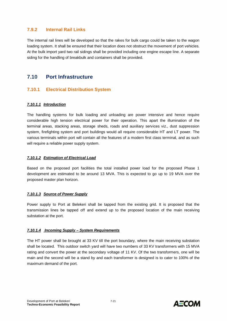
Development of Port at Belekeri 7-21Techno-Economic Feasibility Report
Internal Rail Links7.9.2
The internal rail lines will be developed so that the rakes for bulk cargo could be taken to the wagonloading system. It shall be ensured that their location does not obstruct the movement of port vehicles.At the bulk import yard two rail sidings shall be provided including one engine escape line. A separatesiding for the handling of breakbulk and containers shall be provided.
Port Infrastructure7.10
Electrical Distribution System7.10.1
7.10.1.1 Introduction
The handling systems for bulk loading and unloading are power intensive and hence requireconsiderable high tension electrical power for their operation. This apart the illumination of theterminal areas, stacking areas, storage sheds, roads and auxiliary services viz., dust suppressionsystem, firefighting system and port buildings would all require considerable HT and LT power. Thevarious terminals within port will contain all the features of a modern first class terminal, and as suchwill require a reliable power supply system.
7.10.1.2 Estimation of Electrical Load
Based on the proposed port facilities the total installed power load for the proposed Phase 1development are estimated to be around 13 MVA. This is expected to go up to 19 MVA over theproposed master plan horizon.
7.10.1.3 Source of Power Supply
Power supply to Port at Belekeri shall be tapped from the existing grid. It is proposed that thetransmission lines be tapped off and extend up to the proposed location of the main receivingsubstation at the port.
7.10.1.4 Incoming Supply – System Requirements
The HT power shall be brought at 33 KV till the port boundary, where the main receiving substationshall be located. This outdoor switch yard will have two numbers of 33 KV transformers with 15 MVArating and convert the power at the secondary voltage of 11 KV. Of the two transformers, one will bemain and the second will be a stand by and each transformer is designed is to cater to 100% of themaximum demand of the port.
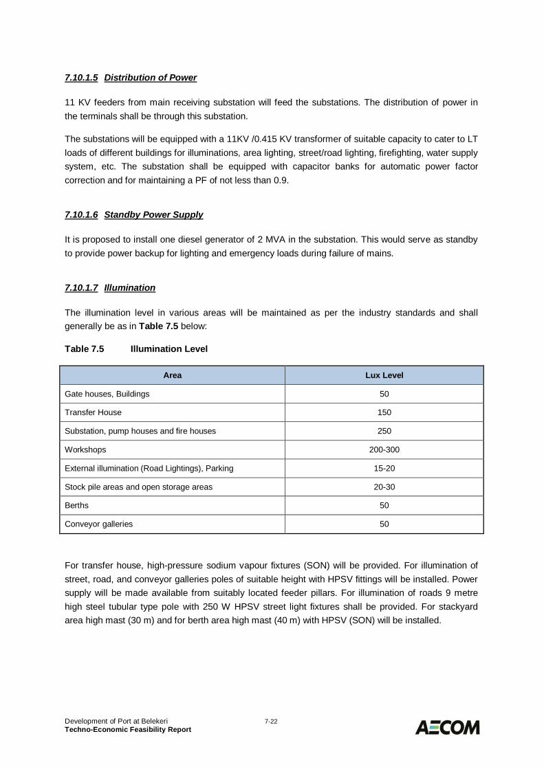
Development of Port at Belekeri 7-22Techno-Economic Feasibility Report
7.10.1.5 Distribution of Power
11 KV feeders from main receiving substation will feed the substations. The distribution of power inthe terminals shall be through this substation.
The substations will be equipped with a 11KV /0.415 KV transformer of suitable capacity to cater to LTloads of different buildings for illuminations, area lighting, street/road lighting, firefighting, water supplysystem, etc. The substation shall be equipped with capacitor banks for automatic power factorcorrection and for maintaining a PF of not less than 0.9.
7.10.1.6 Standby Power Supply
It is proposed to install one diesel generator of 2 MVA in the substation. This would serve as standbyto provide power backup for lighting and emergency loads during failure of mains.
7.10.1.7 Illumination
The illumination level in various areas will be maintained as per the industry standards and shallgenerally be as in Table 7.5 below:
Table 7.5 Illumination Level
Area Lux Level
Gate houses, Buildings 50
Transfer House 150
Substation, pump houses and fire houses 250
Workshops 200-300
External illumination (Road Lightings), Parking 15-20
Stock pile areas and open storage areas 20-30
Berths 50
Conveyor galleries 50
For transfer house, high-pressure sodium vapour fixtures (SON) will be provided. For illumination ofstreet, road, and conveyor galleries poles of suitable height with HPSV fittings will be installed. Powersupply will be made available from suitably located feeder pillars. For illumination of roads 9 metrehigh steel tubular type pole with 250 W HPSV street light fixtures shall be provided. For stackyardarea high mast (30 m) and for berth area high mast (40 m) with HPSV (SON) will be installed.
Development of Port at Belekeri 7-23Techno-Economic Feasibility Report
7.10.1.8 Cables
To meet the HT load requirement 11 KV XLPE aluminium armoured cables will be used. Cables willbe laid on cable trays, ducts, directly buried in ground and in trenches, etc. as per site requirement.
LT power distribution to various services such as illumination, firefighting, air conditioning water supplyetc. will be done through 1.1 kV grade PVC insulated aluminium armoured power cables. Laying ofcables will be done as per site requirement.
Internal wiring to be done in recessed UPVC conduit or on surface with GI conduit and single corePVC insulated FRLS copper wire to be done in case of transfer towers, conveyors, workshops,substations, pump house, fire house, etc.
7.10.1.9 Earthing & Lightning Protection
Suitable lightning protection system will be installed as per the guide lines of the IS: 2309. An efficientearthing and lightning protection system will be designed to ensure protection of men & material inworst of the weather conditions.
7.10.1.10 Power Factor Improvement
Suitable rating HT capacitors with automatic power factor correction arrangement will be installed tomaintain the overall power factor correction to 0.97.
Communication System7.10.2
7.10.2.1 General
The Communication system comprising Radio Communication units, Telephone System and PAsystem of suitable capacities will be provided to suit the port operation requirement.
7.10.2.2 Telephone System
To meet the total port requirements, an EPABX of 100 lines capacity will be installed. Suitabletelephone instruments to suit the site requirement with adequate protection will be provided.
7.10.2.3 Radio Communication
A radio communication system will be installed for transfer of information between various operationalareas of port like Unloaders, MHCr, shore side duties, control room, terminal engineering services,operational management, supervision etc.
Development of Port at Belekeri 7-24Techno-Economic Feasibility Report
7.10.2.4 Public Address System
The public address system will supplement the above two systems. The central control for the systemwill be kept with the control room located at top floor of the administrative building.
Distribution type public address system will provide a comprehensive paging system for oralcommunication and announcement by loud speakers and handset stations with built-in amplifierscovering all working areas of the port terminal. The loud speakers will be mounted on purpose builtsupports provided on permanent structures. The exterior speakers will be weather proof. One numbermaster control station with microphone to zone selection and all call facility will also be provided atcontrol room.
Computerized Information System7.10.3
7.10.3.1 Overall Objectives
The computerised information system proposed for proposed port will have the following objectives:
· Establish one common IT infrastructure that is based on scale operations in order to deliverservices of high quality.
· Enable centralized control of the Infrastructure to ensure effective management and security.· Ensure mobility of users located at different office premises by providing the necessary
services to ensure connectivity from anywhere.· Utilize best practices for technology selection and implementation.
7.10.3.2 Terminal Operating System
Terminal handling equipment will have control systems to maintain and manage bulk terminaloperations. These control systems will be interfaced with BI systems for reporting and MIS. TerminalOperating systems will be deployed for handling the following processes:
· Berth Planning· Terminal Planning, Monitoring and Execution processes· Operations Equipment Control (OEC)· Cargo Control (CC)· Yard Planning, gate delivery and receipt control· Landside planning processes· Enterprise Resource Planning
7.10.3.3 Technology Infrastructure
The IT Infrastructure of Port at Belekeri like hardware, software, network etc. will be implementedaccording to a long-term strategic plan. The capacity plan includes the necessary infrastructure for theIT strategy development as well as to support the general day-to-day IT requirements.
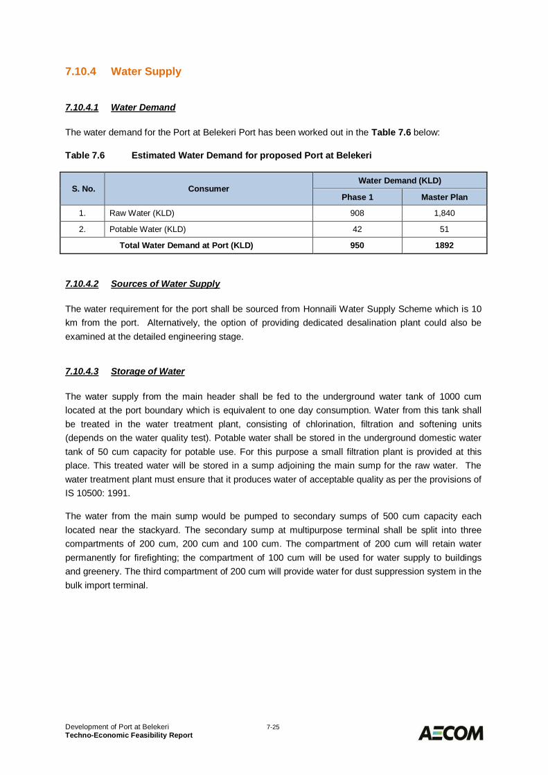
Development of Port at Belekeri 7-25Techno-Economic Feasibility Report
Water Supply7.10.4
7.10.4.1 Water Demand
The water demand for the Port at Belekeri Port has been worked out in the Table 7.6 below:
Table 7.6 Estimated Water Demand for proposed Port at Belekeri
S. No. ConsumerWater Demand (KLD)
Phase 1 Master Plan
1. Raw Water (KLD) 908 1,840
2. Potable Water (KLD) 42 51
Total Water Demand at Port (KLD) 950 1892
7.10.4.2 Sources of Water Supply
The water requirement for the port shall be sourced from Honnaili Water Supply Scheme which is 10km from the port. Alternatively, the option of providing dedicated desalination plant could also beexamined at the detailed engineering stage.
7.10.4.3 Storage of Water
The water supply from the main header shall be fed to the underground water tank of 1000 cumlocated at the port boundary which is equivalent to one day consumption. Water from this tank shallbe treated in the water treatment plant, consisting of chlorination, filtration and softening units(depends on the water quality test). Potable water shall be stored in the underground domestic watertank of 50 cum capacity for potable use. For this purpose a small filtration plant is provided at thisplace. This treated water will be stored in a sump adjoining the main sump for the raw water. Thewater treatment plant must ensure that it produces water of acceptable quality as per the provisions ofIS 10500: 1991.
The water from the main sump would be pumped to secondary sumps of 500 cum capacity eachlocated near the stackyard. The secondary sump at multipurpose terminal shall be split into threecompartments of 200 cum, 200 cum and 100 cum. The compartment of 200 cum will retain waterpermanently for firefighting; the compartment of 100 cum will be used for water supply to buildingsand greenery. The third compartment of 200 cum will provide water for dust suppression system in thebulk import terminal.
Development of Port at Belekeri 7-26Techno-Economic Feasibility Report
Drainage and Sewerage System7.10.5
7.10.5.1 Drainage System
Storm Water Drainage at the port will be through a system of underground covered drains provided todischarge the collected runoff. At the bulk import stackyard, the drainage system would comprise ofopen drains for taking the discharge to the settling pond. Before discharging the collected storm waterinto the main drainage system of the port it would be passed through the necessary filters for furtherreduction of PPM.
Surface drainage system shall be provided in the container yard and other dry storage area throughwhich water shall be diverted to the secondary covered drains, which shall ultimately discharge to themain drain.
7.10.5.2 Solid Waste Management
For the buildings complex having administration building and port user buildings, a small sewagetreatment plant of 20 KLD capacity is proposed. The treated sewage shall be discharged to the maindrainage network. The sludge from the treatment plant will be processed and converted into Biomassused as manure.
For the isolated buildings where the quantity is negligible, it is proposed to construct septic tanks andconnect the septic tank outlets to soak pits for disposal.
There will be very little sewage water generated at the quay walls and hence separate treatmentproposals are not contemplated.
Floating Crafts for Marine Operations7.10.6
7.10.6.1 Tugs
For berthing / un-berthing of the design vessels four harbour tugs of 50 T bollard pull capacity arerequired initially, including tug for standby/ emergency.
7.10.6.2 Pilot cum Security Vessels
These vessels are required for the pilots to travel to and fro between the port and boarding point,where the port’s pilot will embark/disembark the ship. It is proposed to provide two pilot vesselsincluding one standby vessel.

Development of Port at Belekeri 7-27Techno-Economic Feasibility Report
7.10.6.3 Mooring Boats
These boats will be required to carry the lines from the ships and pass it to the required points duringberthing and un-berthing operations. Two boats are required per vessel for berthing and un-berthingoperations. Considering the frequency of the ships, two mooring boats are considered adequate forPhase 1.
7.10.6.4 Harbour Crafts
The requirements of Harbour Crafts for the Phase 1 development of port of Belekeri are given inTable 7.7 below.
Table 7.7 Harbour Craft Requirements
S. No. Harbour Craft Number
1. Tugs 50 T bollard pull 4
2. Pilot cum Security Vessels 2
3. Mooring Boats 2
Navigational Aids7.10.7
7.10.7.1 General
It is envisaged that navigation will be carried out throughout the year, by day and night, except duringcyclonic weather, when rough seas, high wind speeds, and negative storm surge may result inlow/inadequate draft. Navigation aids are required for ensuring safe navigation of ships entering andleaving the port through the approach channel as well as berthing / un-berthing requirements insidethe docks. These aids are such as fairway buoys, port and starboard buoys, leading / transit lights,beacons and Vessel Traffic Management Information System (VTMIS) etc., which are installed onland or in water for guidance to all vessels for safe and regulated navigation in channels, anchorages,berths and docks. VTMIS will have the requisite communication, Radar system integrated into it.
7.10.7.2 Buoys
The approach channel has a total length of 12 km from the breakwater head which require safenavigation and pilotage. It is necessary to mark the channel with suitable number of navigationalbuoys by following the IALA zone ‘A’ code. Considering the need to provide adequate assistance forsafe navigation of the ships, it is recommended to provide paired buoys at a spacing of 1 Nauticalmile. In addition some buoys are proposed in the harbour basins as well. IALA maritime buoyagesystem as per region A, in which Belekeri port falls, will be followed. The lateral marks will be red andgreen colours to denote the port and starboard sides of channel.
Development of Port at Belekeri 7-28Techno-Economic Feasibility Report
7.10.7.3 Leading / Transit lights
Considering the channel being straight and long and adequately marked with navigational buoys, it isnot proposed to install any leading / transit lights to guide the ships through the channel.
7.10.7.4 Beacons / Mole lights
One Beacon at breakwater head is proposed to be provided.
7.10.7.5 Vessel Traffic Management System (VTMS)
The purpose of the VTMS is to provide a clear and concise real time portrayal of vessel movementsand interaction in the Vessel Traffic Service (VTS) area. For Belekeri Port, the service area will be theapproach channel, the anchorage area, the harbour basin etc. This system will be used for marineoperations and will also be linked to the PMIS (Port Management and Information System). Theinformation provided by VTMS system allows the operator or user of the system to:
· Provide the required level of VTS: Information, Assistance or Organisation· Enhance safety of life and property· Reduce risks associated with marine operations· Enhance efficiency of vessel movements and port marine resources· Distribute VTS related information· Provide Search and rescue assistance· Provide VTS data for administrative purposes, analysis of incidents and planning
The VTS in recent years has changed from Traffic Monitoring to Traffic Planning by introduction andinterconnection of databases and expert systems. It allows access of static and dynamic informationabout ships, their cargo and port service requirements. Together with an automatic update of trafficinformation the VTMS provides a powerful tool for programming of traffic movement within thesurveillance area. Operators can associate tracked targets with vessels registered in the database,which makes the data readily available and allows the system to automatically provide pertinentvoyage information to other port service providers.
Security System Complying with ISPS7.10.8
Security system of the port is required to provide sufficient protection against:
· Sabotage· pilferage and thefts· encroachments by unauthorised persons· trespassers and antisocial elements
The security system must comply with the requirements of ISPS Code.
Keeping in view the importance of various areas in the port, the following proposals are made:
Development of Port at Belekeri 7-29Techno-Economic Feasibility Report
· The custom bound area will be provided with a rubble masonry wall 2.4 m high with barbedwire fencing of 1 m high over the wall.
· A security office and check post at the entrance to the terminals.· Provision of watch towers at suitable intervals for manual monitoring with night vision
binoculars for use during nights.· Adequate isolated area would be allocated for storage of dangerous goods· The lighting in the port area shall be to the acceptable standards· Close circuit Television system (CCTV) to capture activities at all vantage, vulnerable and
sensitive locations.
The security arrangements proposed would have to be to the approval of the Director General ofShipping who is the designated authority under the ISPS code.
Firefighting System7.10.9
7.10.9.1 General
The firefighting system shall be designed to be capable of both controlling and extinguishing fires.The firefighting system for berths and terminal areas will be a fresh water system with a separatepump house with pumps which will draw water from the respective fresh water tanks.
A centralised fire station will be provided for attending to all calls which will house two mobile firetenders. One fire tender will be provided with snorkel attachment.
7.10.9.2 Dry Bulk Berths and Stackyard
It is proposed to install Fire Hydrant System, which shall be designed to give adequate fire protectionfor the facility based on Indian Standard or equivalent and shall conform to the provisions of the TariffAdvisory Committee's fire protection Manual.
Fire hydrant system is proposed at the following areas, which are classified as ordinary hazard areas.
· Berths· Stackyards· Wagon Loading Station· All galleries of Coal Conveyors
The fire hydrant system shall be designed to ensure that adequate quantity of water is available at alltimes, at all areas of the facility where a potential fire hazard exists. Each hydrant connection shall beprovided with suitable length of hoses and nozzles to permit effective operation.
7.10.9.3 Container cum Multipurpose Terminal
The firefighting system shall be designed to give suitable fire protection for thecontainerised/breakbulk cargo and container handling facilities in the terminal and shall conform to theprovision of Tariff Advisory Committee’s fire protection manual. The firefighting system shall be acombination of water hydrants, fire alarm system and fire extinguishers.
Development of Port at Belekeri 7-30Techno-Economic Feasibility Report
Pollution Control7.10.10
7.10.10.1 General
One of the essential regulatory functions of a Port Authority is to ensure that the port waters are freefrom pollution. To this end, pollution control assumes a significant role in any port operations. Themain sources of pollution during operations in the port are:
· Discharge of oil by ships / crafts.· Discharge of bilge by ships / crafts.· Discharge of dirty / contaminated ballast by ships.· Discharge of cargo overboard.· Spillage of cargo during unloading / loading operations.· Discharge of garbage, sweepings, sewage, etc.· Discharge of industrial effluents.· Municipal sewage and drainage.· Dust from cargo.· Smoke from ships, vehicles.· Noise from vehicles, machinery.· Accidents
7.10.10.2 Dust Suppression
Dust control equipment is proposed for efficient control of dust pollution to the environment duringstorage and handling of thermal coal at the berth and stackyard. An efficient dust suppression systemwill contain dust particles before it becomes airborne.
A system consisting of pumps, storage tank, nozzles for dust suppression at discharge / feedingpoints of belt conveyors have been proposed at each transfer tower for efficient dust control. Inaddition to above, suitable spray system shall also be provided at ship unloader, coal stackyard andwagon loading station.
The water pumping system shall be designed to operate only when it is required thus saving energy.The spray in dust generation area shall operate only when material is being handled in that location.
Development of Port at Belekeri 8-1Techno-Economic Feasibility Report
ENVIRONMENTAL SETTINGS AND IMPACT8.0EVALUATIONIntroduction8.1
This section presents environmental conditions in and around the proposed port location at Bhavikeriabout 4 km south of Belekeri. It briefly describes general environmental conditions of the project area,i.e., physical environment, flora and fauna; identifies environmental issue that may arise due to theconsidered project and its components, suggests mitigation measures to minimise adverse impacts.This section also details environmental policies and legislation to highlight the permissions andclearances required for the project.
The section is largely based on the review of literature, available secondary data and informationgathered during the site visits.
General8.2Bhavikeri is located in Ankola Taluka of Uttara Kannada District in the state of Karnataka. As perCensus of India 2011 it has total population of 8160 from 1911 households. Total male population isabout 4058 as compared to 4102 females. Average Sex Ratio of Bhavikeri village is 1011 which ishigher than Karnataka state average of 973. Bhavikeri village has higher literacy rate of 83.66%,where 90.52% males and 76.91% of females are literate.
Rain-fed agriculture activities are prevalent in the area where rice and groundnut are sownpredominantly. Other crops that are grown in this area are coconut, Arecanut, Cashew, Banana,Water Melon and other leafy vegetables.
Site Setting8.3A Greenfield port is planned to be developed on the coast near the Bhavikeri village. The waterfrontidentified for port development has a small village Keni in the immediate vicinity, while Bhavikerivillage is about 500 m east of the sea coast (Figure 8.1).
About 100-120 households were found to be located in the village Keni and a total population of about2000 has been reported. The villagers are mainly involved in small scale fishing and also agriculturalactivities.
The coast has rocky outcrops and is also demarcated as stable (Figure 8.2).
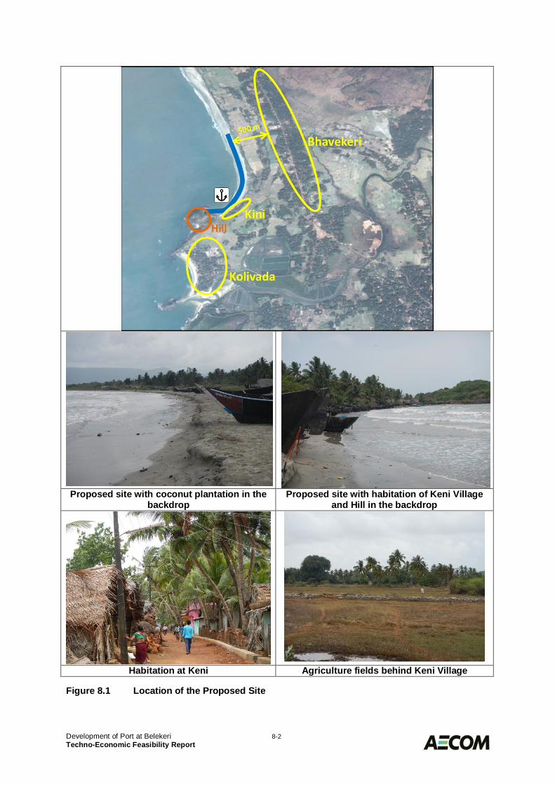
Development of Port at Belekeri 8-2Techno-Economic Feasibility Report
Proposed site with coconut plantation in thebackdrop
Proposed site with habitation of Keni Villageand Hill in the backdrop
Habitation at Keni Agriculture fields behind Keni Village
Figure 8.1 Location of the Proposed Site
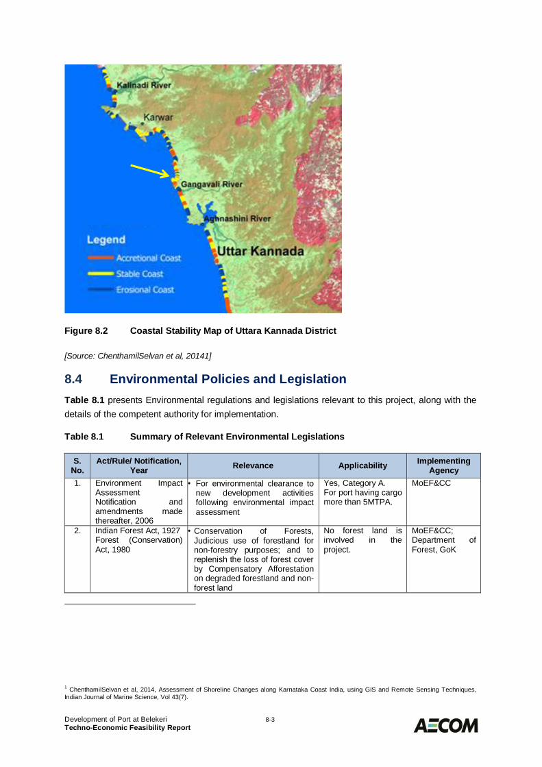
Development of Port at Belekeri 8-3Techno-Economic Feasibility Report
Figure 8.2 Coastal Stability Map of Uttara Kannada District
[Source: ChenthamilSelvan et al, 20141]
Environmental Policies and Legislation8.4Table 8.1 presents Environmental regulations and legislations relevant to this project, along with thedetails of the competent authority for implementation.
Table 8.1 Summary of Relevant Environmental Legislations
S.No.
Act/Rule/ Notification,Year Relevance Applicability Implementing
Agency1. Environment Impact
AssessmentNotification andamendments madethereafter, 2006
· For environmental clearance tonew development activitiesfollowing environmental impactassessment
Yes, Category A.For port having cargomore than 5MTPA.
MoEF&CC
2. Indian Forest Act, 1927Forest (Conservation)Act, 1980
· Conservation of Forests,Judicious use of forestland fornon-forestry purposes; and toreplenish the loss of forest coverby Compensatory Afforestationon degraded forestland and non-forest land
No forest land isinvolved in theproject.
MoEF&CC;Department ofForest, GoK
1 ChenthamilSelvan et al, 2014, Assessment of Shoreline Changes along Karnataka Coast India, using GIS and Remote Sensing Techniques,Indian Journal of Marine Science, Vol 43(7).
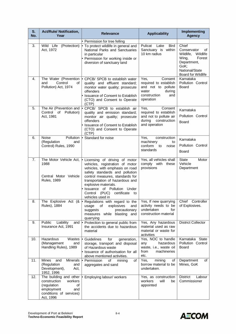
Development of Port at Belekeri 8-4Techno-Economic Feasibility Report
S.No.
Act/Rule/ Notification,Year Relevance Applicability Implementing
Agency· Permission for tree felling
3. Wild Life (Protection)Act, 1972
· To protect wildlife in general andNational Parks and Sanctuariesin particular
· Permission for working inside ordiversion of sanctuary land
Pulicat Lake BirdSanctuary is within10 km radius
ChiefConservator ofWildlife, WildlifeWing, ForestDepartment,GoK;National/StateBoard for Wildlife
4. The Water (Preventionand Control ofPollution) Act, 1974
· CPCB/ SPCB to establish waterquality and effluent standard;monitor water quality; prosecuteoffenders
· Issuance of Consent to Establish(CTO) and Consent to Operate(CTP)
Yes, Consentrequired to establishand not to pollutewater duringconstruction andoperation
KarnatakaPollution ControlBoard
5. The Air (Prevention andControl of Pollution)Act, 1981
· CPCB/ SPCB to establish airquality and emission standard;monitor air quality; prosecuteoffenders
· Issuance of Consent to Establish(CTO) and Consent to Operate(CTP)
Yes, Consentrequired to establishand not to pollute airduring constructionand operation
KarnatakaPollution ControlBoard
6. Noise Pollution(Regulation andControl) Rules, 1990
· Standard for noise Yes, constructionmachinery toconform to noisestandards
KarnatakaPollution ControlBoard
7. The Motor Vehicle Act,1988
Central Motor VehicleRules, 1989
· Licensing of driving of motorvehicles, registration of motorvehicles, with emphasis on roadsafety standards and pollutioncontrol measures, standards fortransportation of hazardous andexplosive materials.
· Issuance of Pollution UnderControl (PUC) certificate tovehicles used in
Yes, all vehicles shallcomply with theseprovisions
State MotorVehicleDepartment
8. The Explosive Act (&Rules), 1884
· Regulations with regard to theusage of explosives andsuggests precautionarymeasures while blasting andquarrying
Yes, If new quarryingactivity needs to beundertaken forconstruction material
Chief Controllerof Explosives.
9. Public Liability andInsurance Act, 1991
· Protection to general public fromthe accidents due to hazardousmaterial
Yes, Any hazardousmaterial used as rawmaterial or waste foractivities
District Collector
10. Hazardous Wastes(Management andHandling Rules), 1989
· Guidelines for generation,storage, transport and disposalof Hazardous waste
· Issuance of authorisation for allabove mentioned activities.
Yes, NOC to handleany hazardouswaste, i.e., waste oilfrom machineriesetc.
Karnataka StatePollution ControlBoard
11. Mines and Minerals(Regulation andDevelopment), Act,1952, 1996
· Permission of mining ofaggregates and sand
Yes, mining ofborrow material to beundertaken.
Department ofMines, GoK
12. The building and otherconstruction workers(regulation ofemployment andconditions of services)Act, 1996
· Employing labour/ workers Yes, as constructionworkers will beappointed
District LabourCommissioner
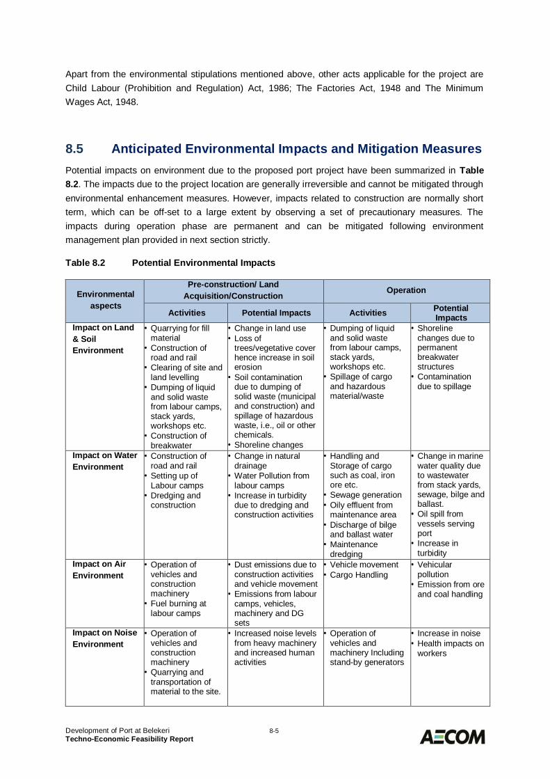
Development of Port at Belekeri 8-5Techno-Economic Feasibility Report
Apart from the environmental stipulations mentioned above, other acts applicable for the project areChild Labour (Prohibition and Regulation) Act, 1986; The Factories Act, 1948 and The MinimumWages Act, 1948.
Anticipated Environmental Impacts and Mitigation Measures8.5Potential impacts on environment due to the proposed port project have been summarized in Table8.2. The impacts due to the project location are generally irreversible and cannot be mitigated throughenvironmental enhancement measures. However, impacts related to construction are normally shortterm, which can be off-set to a large extent by observing a set of precautionary measures. Theimpacts during operation phase are permanent and can be mitigated following environmentmanagement plan provided in next section strictly.
Table 8.2 Potential Environmental Impacts
Environmentalaspects
Pre-construction/ LandAcquisition/Construction Operation
Activities Potential Impacts Activities PotentialImpacts
Impact on Land& SoilEnvironment
· Quarrying for fillmaterial
· Construction ofroad and rail
· Clearing of site andland levelling
· Dumping of liquidand solid wastefrom labour camps,stack yards,workshops etc.
· Construction ofbreakwater
· Change in land use· Loss of
trees/vegetative coverhence increase in soilerosion
· Soil contaminationdue to dumping ofsolid waste (municipaland construction) andspillage of hazardouswaste, i.e., oil or otherchemicals.
· Shoreline changes
· Dumping of liquidand solid wastefrom labour camps,stack yards,workshops etc.
· Spillage of cargoand hazardousmaterial/waste
· Shorelinechanges due topermanentbreakwaterstructures
· Contaminationdue to spillage
Impact on WaterEnvironment
· Construction ofroad and rail
· Setting up ofLabour camps
· Dredging andconstruction
· Change in naturaldrainage
· Water Pollution fromlabour camps
· Increase in turbiditydue to dredging andconstruction activities
· Handling andStorage of cargosuch as coal, ironore etc.
· Sewage generation· Oily effluent from
maintenance area· Discharge of bilge
and ballast water· Maintenance
dredging
· Change in marinewater quality dueto wastewaterfrom stack yards,sewage, bilge andballast.
· Oil spill fromvessels servingport
· Increase inturbidity
Impact on AirEnvironment
· Operation ofvehicles andconstructionmachinery
· Fuel burning atlabour camps
· Dust emissions due toconstruction activitiesand vehicle movement
· Emissions from labourcamps, vehicles,machinery and DGsets
· Vehicle movement· Cargo Handling
· Vehicularpollution
· Emission from oreand coal handling
Impact on NoiseEnvironment
· Operation ofvehicles andconstructionmachinery
· Quarrying andtransportation ofmaterial to the site.
· Increased noise levelsfrom heavy machineryand increased humanactivities
· Operation ofvehicles andmachinery Includingstand-by generators
· Increase in noise· Health impacts on
workers
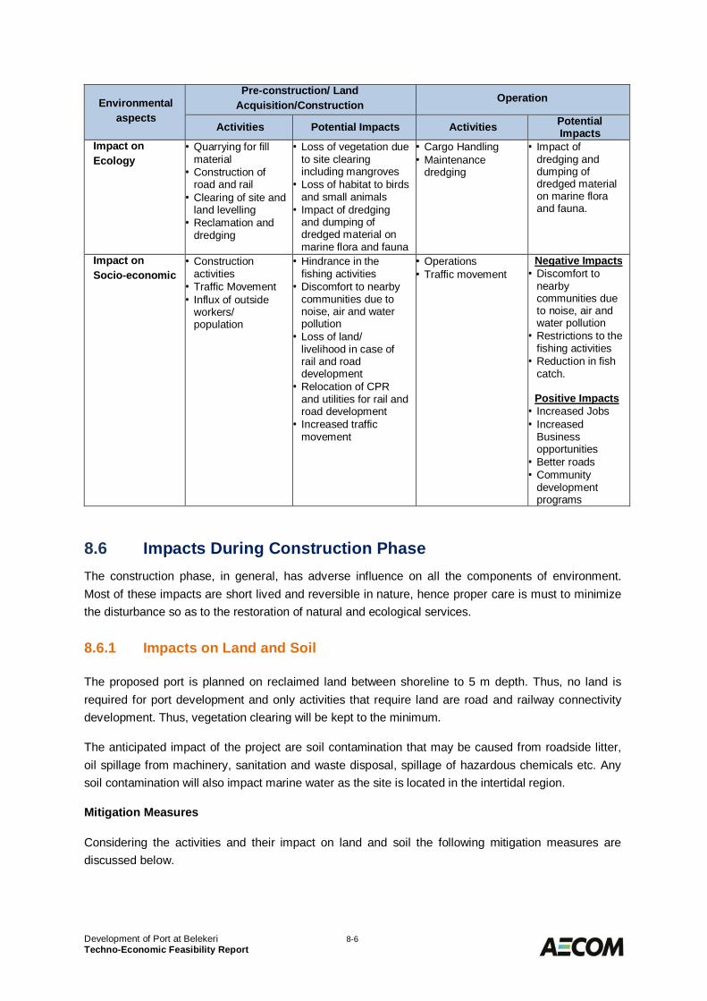
Development of Port at Belekeri 8-6Techno-Economic Feasibility Report
Environmentalaspects
Pre-construction/ LandAcquisition/Construction Operation
Activities Potential Impacts Activities PotentialImpacts
Impact onEcology
· Quarrying for fillmaterial
· Construction ofroad and rail
· Clearing of site andland levelling
· Reclamation anddredging
· Loss of vegetation dueto site clearingincluding mangroves
· Loss of habitat to birdsand small animals
· Impact of dredgingand dumping ofdredged material onmarine flora and fauna
· Cargo Handling· Maintenance
dredging
· Impact ofdredging anddumping ofdredged materialon marine floraand fauna.
Impact onSocio-economic
· Constructionactivities
· Traffic Movement· Influx of outside
workers/population
· Hindrance in thefishing activities
· Discomfort to nearbycommunities due tonoise, air and waterpollution
· Loss of land/livelihood in case ofrail and roaddevelopment
· Relocation of CPRand utilities for rail androad development
· Increased trafficmovement
· Operations· Traffic movement
Negative Impacts· Discomfort to
nearbycommunities dueto noise, air andwater pollution
· Restrictions to thefishing activities
· Reduction in fishcatch.
Positive Impacts· Increased Jobs· Increased
Businessopportunities
· Better roads· Community
developmentprograms
Impacts During Construction Phase8.6The construction phase, in general, has adverse influence on all the components of environment.Most of these impacts are short lived and reversible in nature, hence proper care is must to minimizethe disturbance so as to the restoration of natural and ecological services.
Impacts on Land and Soil8.6.1
The proposed port is planned on reclaimed land between shoreline to 5 m depth. Thus, no land isrequired for port development and only activities that require land are road and railway connectivitydevelopment. Thus, vegetation clearing will be kept to the minimum.
The anticipated impact of the project are soil contamination that may be caused from roadside litter,oil spillage from machinery, sanitation and waste disposal, spillage of hazardous chemicals etc. Anysoil contamination will also impact marine water as the site is located in the intertidal region.
Mitigation Measures
Considering the activities and their impact on land and soil the following mitigation measures arediscussed below.
Development of Port at Belekeri 8-7Techno-Economic Feasibility Report
· Vegetation clearance shall be confined to the minimum area required for the project.· Re-plantation shall be taken up followed by construction in another identified area.· All the waste has to be collected and nothing to be dumped on land or water.· The contractor will be held responsible to clean all debris before leaving the construction site
and also to make necessary arrangements with scrap dealers to sell off the waste scraps.· The waste from labour camps and administrative activities during construction will all be
disposed to a designated solid waste collection point.
Impacts on Water Quality8.6.2
Impacts on water resource are two-fold, one increased water demand and disposal of waste water.
Additional water demand due to this project is anticipated towards construction activities and drinkingwater needs for labours and employees. The water will be sourced from Honnalli Water Supplyscheme, for which all the required permissions from the state authorities will be sought.
It is generally assumed that 80% of the domestic consumption is generated as sewage, which ifdischarged untreated will act as a source of water pollution. During construction phase, sewage of 20m3/day is expected to be generated.
Other sources of contamination are accidental disposal of construction debris and spillage of oil andgrease from the vehicles and construction machineries.
The construction activities have potential influence on the water resources within the activity area. Thepile driving, rock cutting and dredging will cause high turbidity, removal of nutrient due to dredging,which would ultimately affect the marine flora and fauna.
Natural drainage may be impacted due to the provision of the road network and hence it needs carefulplanning.
Mitigation Measures
In order to mitigate negative impacts on water that are expected from the projects, the followingmeasures will be implemented:
· Bore wells, if required to source water for construction phase will be drilled after an exhaustivehistorical study of the region and after obtaining necessary permission and approvals from thestate water board or Central Ground water Authority.
· Water cess shall also be paid to relevant authority.· The embankments of any surface water bodies will be raised to prevent contamination from
run-off.· Workers shall be provided proper sanitation facilities including mobile toilets or 10 ‘Sulabh
Shauchalayas’ (community toilets).· All the waste water will be collected and treated using soak pits and sludge from soak pits will
be cleaned.· The construction site and camp will be provided with temporary drainage.· Avoid water stagnation/ ponding near work and camp sites to curb vector borne diseases.· Fuel/ oil storage will be stored away from any watercourses.· Leakage of oil wastes from oil storage and vehicles shall be avoided in order to prevent
potential contamination of streams or ground water.
Development of Port at Belekeri 8-8Techno-Economic Feasibility Report
· Surface runoff from machine operations, oil handling areas/devices will be treated for oilseparation before being discharged into the sea or river.
· Waste Oil/ grease/ lubricants are categorized by MoEF as Hazardous Wastes. All such wastewill be collected and stored at a protected place and sold to a vendor authorized by KPCB orMoEF.
· No construction activity will be undertaken during monsoon period.· Use of silt curtains is recommended to confine areas of high turbidity during dredging and pile
driving.· To avoid impacts from dumping of dredged material the following measures shall be adopted:
o Most of the quantity of dredged material will be used as reclamation material and forrevetments.
o Limited material, which will not be suitable for reclamation, will be disposed off at anidentified site beyond 20 m depths in the sea.
o Areas with high fish yield or used by locals for fishing shall be avoided.o Dumping activity shall not be carried out during monsoon season.o To reduce the potential for error on the part of the contractor, efforts should be made to
monitor regularly the activities during dredging and disposal of spoils.o Where appropriate, disposal vessels should be equipped with accurate positioning
systems. Disposal vessels and operations should be inspected regularly to ensure thatthe conditions of the disposal permit are being complied with and that the crews areaware of their responsibilities under the permit.
Impact of Air Quality8.6.3
Air emissions due to construction activities, fuel burning, vehicle movement, machinery and DG setsare the most significant sources of air pollution during construction phase.
Air pollution can cause significant impacts on the environment, and subsequently on humans,animals, vegetation and materials. It primarily affects the respiratory, circulatory and olfactory systemsin humans. In most cases, air pollution aggravates pre-existing diseases or degrades health status,making people more susceptible to other infections or the development of chronic respiratory andcardiovascular diseases.
Mitigation Measures
· Power supply from State Electricity Board shall be sourced for electrically operatedconstruction machinery/equipment.
· The use of DG set would be limited to backup during power failure.· Dust suppression systems (water spray) will be used near the earth handling sites, asphalt
mixing sites and other excavation areas to reduce the wind-blown fugitive dust emissions.· Earth moving equipment, such as bulldozer with a grader blade and ripper will be used for
excavation work.· Excess idling of construction equipment as well as vehicles to be prohibited.· Vehicles and construction equipment will be fitted with internal devices i.e. catalytic converters
to reduce CO and HC emissions.· All stationary machines/ DG sets / construction equipment emitting the pollutants will be
inspected weekly for maintenance and shall be fitted with exhaust pollution control devices.· Vehicles and machineries will be regularly maintained to conform to the emission standards
stipulated under Environment (Protection), Rules 1986.· “No Objection Certificate (NoC)” for setting up of crusher, hot-mix plant and DGs will be
obtained from Karnataka Pollution Control Board.
Development of Port at Belekeri 8-9Techno-Economic Feasibility Report
· Ensure that all vehicles must possess Pollution under Control (PUC) Certificate and shall berenewed accordingly.
· All the roads in the vicinity of Port site and the roads connecting quarry sites to constructionsites will be paved to minimize the fugitive emissions.
· If any of the road stretches are not paved due to some reason, then adequate arrangementswill be made to spray water on such stretches of the road.
· The labours shall be provided with clean fuel so that they neither cut the trees for fuel woodnor burn firewood.
Impacts on Noise Quality8.6.4
During construction phase, there could be high noise levels due to operation of various constructionequipment and increased number of vehicles supplying man and material to the site. It is known thatcontinuous exposure to high noise levels above 90 dBA affects the hearing acuity of theworkers/operators or residents and hence, require mitigation planning.
Mitigation Measures
· The construction works will be carried out during the day time. The work hours should belimited depending on convenience of the local people.
· Noise levels of machineries used shall conform to relevant standards prescribed inEnvironment (Protection) Rules, 1986. Workers shall not be exposed to noise level more thanpermitted for industrial premises, i.e. 90 dBA (Leq) for 8 hours.
· Exposure of workers near the high noise levels areas can be minimized. This can be achievedby job rotation/automation, use of ear plugs, etc.
· Labour camps shall be established away from high noise generating area. Workers exposedto high noise level shall use ear plugs or ear muffs.
· Regular maintenance of all vehicles and machinery shall be made mandatory to keep noiseunder check.
· Nearby communities will be notified of the construction schedule and construction works shallbe structured to daylight working hours.
· Any ‘High Noise Area’ shall be posted with warning signs and will have restricted access.· Noise from air compressors could be reduced by fitting exhaust mufflers and intake mufflers.· Chassis and engine structural vibration noise can be dealt with by isolating the engine from
the chassis and by covering various sections of the engines.· Crushers, if any, will be fitted with rock lining to act as natural sound insulator during the
crushing process.· Noise levels from the construction equipment can be reduced by fitting of exhaust mufflers
and the provision of damping on the steel tool.· It is proposed to develop a greenbelt within the port premises including along the road
stretches.· Noise from the DG set should be controlled by providing an acoustic enclosure or by treating
the enclosure acoustically.· Regular monitoring and maintenance of all the equipment and DG sets shall be taken up to
keep a note on noise levels and to take corrective actions.
Development of Port at Belekeri 8-10Techno-Economic Feasibility Report
Impacts on Ecology8.6.5
Although the land requirement for port development is not envisaged but any development to providefor rail and road connectivity will require careful planning to avoid sensitive locations (habitation,vegetation etc.). Tree cutting is inevitable at this location for infrastructure development.
Pile driving, deposition of rubble, sand compaction and other construction work in water may causeincrease in sediment concentration, which may also reduce sunlight penetration. Disturbance fromconstruction activities may cause displacement of fishery resources and other mobile bottom biota.
Mitigation Measures
· All care shall be taken that trees shall be protected as far as possible while site clearing andinfrastructure development.
· In consultation with Forest Department, more than twice number of the trees will be planted inlieu of trees removed.
· Detailed ecological survey shall be conducted during detailed EIA study to assess theimpacts.
· No construction activity will be allowed during the monsoon season so as to avoid breedingperiod of fishes.
· Use of silt curtains is recommended to confine areas of high turbidity during dredging and pilediving.
· Controlled dumping of the dredged material will be carried out beyond 20 m depths in the seaas a designated site.
· Areas with high fish yield or used by locals for fishing shall be avoided.· All care shall be taken to avoid mangroves vegetation while construction activity. It is also
proposed to plan and develop mangroves in the area identified and suggested by ForestDevelopment.
Impact on Social Conditions8.6.6
During the site visit no major settlement were seen at the proposed site. In addition, no major socialimpacts associated with the proposed port like loss of land and associated lively hood activities isanticipated as proposed port will be developed on reclaimed land.
However, limited acquisition of land and loss of livelihood is anticipated for the provision of rail androad connectivity.
Mitigation Measures
· It is proposed that existing roads will be strengthened wherever possible and as far aspossible government land will be used for rail and road alignment.
· Detail survey of the land will be undertaken to ascertain land losers, properties etc. fallingwithin the area. Each stakeholder will be adequately compensated as per governmentregulations.
· A Rehabilitation and Resettlement (R&R) plan has also been put forth to take up activities forwell-being of affected families and panchayats.
Development of Port at Belekeri 8-11Techno-Economic Feasibility Report
Impacts During Operation Phase8.7
Impact on Water Quality8.7.1
The most likely impacts from the operation phase of the project will be on the marine water, primarilydue to (a) effluent from coal stack yard; (b) oily wastes such as bilge water, washing water, lubricantoil and other residues from vessels and machineries (c) sewage; (d) cargo spillage. All these may leadto odour and degradation of water quality.
Mitigation Measures
· An aerated lagoon is proposed to be provided for treatment of effluent from domestic sourcesand the settled sludge will be dried in sludge drying beds and then used as manure for localuse.
· Effluent generated from coal stack yard will be treated in a settling tank. The sludge producedwill be mainly coal dust, which will be dried on sludge drying beds.
· The effluent from workshops, oil storage, etc. will contain oil and grease particles which shallbe treated in an oil skimmer. The collected oily matter is stored in cans and disposed of atthrough authorised waste recycler.
· To combat oil pollution near the port, inflatable type containment boom with oil skimmers willbe provided at the berth. A clean sweep oil recovery unit consisting of a power pack and therecovery unit mounted on a system will also be deployed for this purpose.
· Any kind of spill, release and other pollution incidents is to be reported promptly to thecoastguard personnel to take appropriate actions.
· Strom water drain shall be made to collect run off from rain but care shall be taken that it isnot contaminated.
· The ships will not be allowed to discharge their sewage in the port complex. As per MARPOLconvention, the ships are now required to have STP on board.
· The International Convention Guidelines for the Prevention of Pollution from Ships, 1973, asmodified by the Protocol of 1978 (MARPOL, 73/78) will be strictly adhered at proposed Portarea for prevention of marine pollution.
Impact on Air Quality8.7.2
Vehicle traffic to service cargo at the port, emissions from port equipment, cargo handling (Coal, ironore, etc.) and fuel burning at labour camps are the major source of air pollution during operationphase.
The coal stock pile is another potential source for entrainment of fugitive coal dust.
Mitigation Measures
· As such, a system consisting of pumps, storage tank, nozzles for dust suppression atdischarge feeding points of belt conveyors will be provided at each transfer tower for efficientdust control.
· In addition to above, a suitable spray system will also be provided at ship unloader, coal stackyard & wagon loading station. The effluent generated by washing from coal terminal will betreated in a settling tank and sludge so produced dried on sludge drying beds.
Development of Port at Belekeri 8-12Techno-Economic Feasibility Report
· All vehicles shall have a valid PUC certificate and regular maintenance shall be mandated.· All the roads in the vicinity of the project site will be paved or black topped to minimize the
entrainment of fugitive emissions.· If any of the road stretches cannot be blacktopped or paved due to some reason, then
adequate arrangements will be made to spray water on such stretches of the road.· For wind generated dust, a windshield with a wire mesh fencing with fast growing creepers up
to a height of 10 m around the stackyard shall be installed.· In addition to all the above measures, a 10 m wide greenbelt will be developed for dust
arresting proposes.· It will be a responsibility of labour contractors to provide for clean fuel to the labours.
Impact on Noise Quality8.7.3
As discussed in construction phase, noise due to equipment and vehicles and human activities will bechief sources. Noise from vehicles can be attributed to the engine, vibration, friction between tyresand the road, and horns. Increased levels of noise depend upon volume of traffic, road condition,vehicle condition, vehicle speed, congestion of traffic and the distance of the receptor from the source.
Mitigation Measures
· Noise levels of port equipment used shall conform to relevant standards prescribed inEnvironment (Protection) Rules, 1986. Workers shall not be exposed to noise level more thanpermitted for industrial premises, i.e. 90 dBA (Leq) for 8 hours;
· Exposure of workers near the high noise levels areas shall be minimized. This can beachieved by job rotation/automation, use of ear plugs, etc.
· Labour camps shall be established away from high noise generating area. Workers exposedto high noise level shall use ear plugs or ear muffs;
· Regular maintenance of all vehicles and machinery shall be made mandatory to keep noiseunder check;
· Any ‘High Noise Area’ shall be posted with warning signs and will have restricted access.· It is proposed to develop a greenbelt within the port premises including along the road
stretches.· Noise from the DG set should be controlled by providing an acoustic enclosure or by treating
the enclosure acoustically.· Regular monitoring and maintenance of all the equipment and DG sets shall be taken up to
keep a note on noise levels and to take corrective actions.
Impact on Ecology8.7.4
Once port is in operation, major impacts are anticipated from vessel movement, cargo handling, wastewater discharge and disturbance due to maintenance dredging.
Release of heavy metals and other chemicals and compounds from the spilled cargo in long run maycause bioaccumulation of these substances in sediment as well as marine flora and fauna.
The constituents of oil are toxic to marine life and release of oil contents on to water will result in formationof a shining film on the surface of water which prevents dissolution of oxygen across the surface of water.Moreover, oil gets accumulated on the body of the small species of fish or invertebrates and coat feathersand fur, reducing birds' and mammals' ability to maintain their body temperatures.
Development of Port at Belekeri 8-13Techno-Economic Feasibility Report
Due to maintenance dredging, some quantity of dredged disposal is anticipated.
Once the project is operation, a green belt will be developed around the ports site and shoreline.
Mitigation Measures
The following actions shall be taken to avoid any major damage due to oil spill:
· Indian Coast Guard (CG) is the Central Coordinating Authority for Oil Spill Response, so incase of any such event CG shall be informed immediately.
· All the measures shall be taken according to the “Guidelines and Policy for use of OSD inIndian Waters” issued in 2002 and in consent with CG.
· Booms, skimmers and dispersant inventory shall be maintained to contain spill at the portlocation.
· All recovered oily material shall be disposed-off properly. Either to waste oil dealers ordumped in secured landfill sites.
· Role and responsibility of personnel taking part in oil spill emergency shall be clearly spelledout.
· Regular drill for oil spill containment shall be conducted and any lag shall be recorded andcorrected.
Impact on Socio-Economic Conditions8.7.5
It is envisaged that during operation stage impacts are mostly positive in nature. Once the projectis operational, the project has several benefits to the immediate affected community and society in large.The following positive impacts envisaged from the project:
· Employment generation for locals· Development of road and rail connectivity· Business opportunity due to ware-housing, cargo handling (stevedoring), transport
requirements.
In addition, under Corporate Social Responsibility initiatives will be undertaken in consultation with thelocal administration and local population to benefit local population and environment. The key thrustareas for CSR activities will be:
· Environment· Primary Education· Health Care· Employment Skill & Job Trainings· Environmental Services and climate resilience.
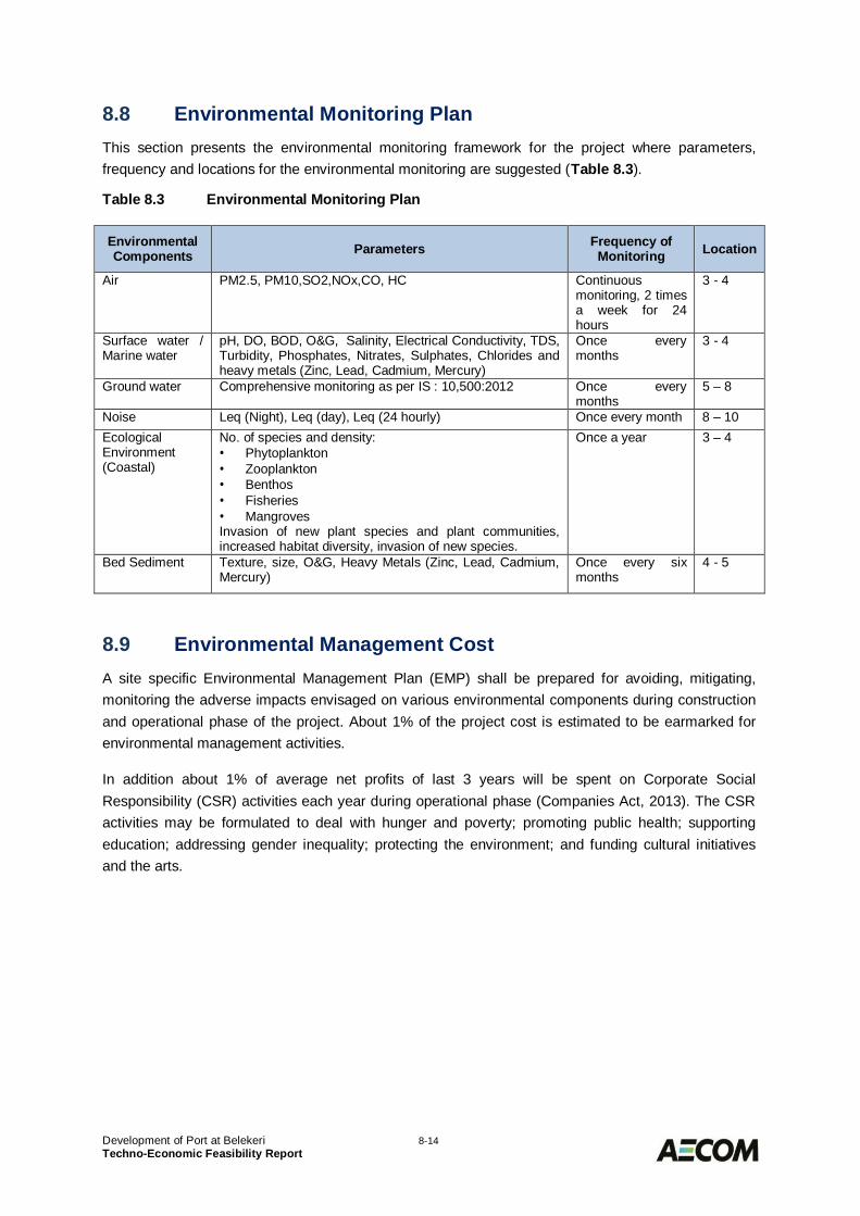
Development of Port at Belekeri 8-14Techno-Economic Feasibility Report
Environmental Monitoring Plan8.8This section presents the environmental monitoring framework for the project where parameters,frequency and locations for the environmental monitoring are suggested (Table 8.3).
Table 8.3 Environmental Monitoring Plan
EnvironmentalComponents Parameters Frequency of
Monitoring Location
Air PM2.5, PM10,SO2,NOx,CO, HC Continuousmonitoring, 2 timesa week for 24hours
3 - 4
Surface water /Marine water
pH, DO, BOD, O&G, Salinity, Electrical Conductivity, TDS,Turbidity, Phosphates, Nitrates, Sulphates, Chlorides andheavy metals (Zinc, Lead, Cadmium, Mercury)
Once everymonths
3 - 4
Ground water Comprehensive monitoring as per IS : 10,500:2012 Once everymonths
5 – 8
Noise Leq (Night), Leq (day), Leq (24 hourly) Once every month 8 – 10EcologicalEnvironment(Coastal)
No. of species and density:· Phytoplankton· Zooplankton· Benthos· Fisheries· MangrovesInvasion of new plant species and plant communities,increased habitat diversity, invasion of new species.
Once a year 3 – 4
Bed Sediment Texture, size, O&G, Heavy Metals (Zinc, Lead, Cadmium,Mercury)
Once every sixmonths
4 - 5
Environmental Management Cost8.9A site specific Environmental Management Plan (EMP) shall be prepared for avoiding, mitigating,monitoring the adverse impacts envisaged on various environmental components during constructionand operational phase of the project. About 1% of the project cost is estimated to be earmarked forenvironmental management activities.
In addition about 1% of average net profits of last 3 years will be spent on Corporate SocialResponsibility (CSR) activities each year during operational phase (Companies Act, 2013). The CSRactivities may be formulated to deal with hunger and poverty; promoting public health; supportingeducation; addressing gender inequality; protecting the environment; and funding cultural initiativesand the arts.
Development of Port at Belekeri 9-1Techno-Economic Feasibility Report
COST ESTIMATES AND IMPLEMENTATION9.0SCHEDULECapital Cost Estimates9.1
General9.1.1
The capital cost estimates prepared for the project are based on the project descriptions and drawingsgiven under the relevant sections of the present report. The drawings were prepared after carrying outbasic engineering of various components of the project. The quantities have been calculated from thedrawings for cost estimation purpose. The basis of the costing is as follows:
· The cost estimates of civil works have been prepared on the basis of current rates for variousitems of work prevailing in the region and also on the past costs for similar works elsewhere.
· The costs of equipment and machinery are based on budgetary quotations and discussionsheld with the manufacturers and also in-house data. The costs include all taxes, duties,insurance freight etc.
· The price level used for the estimates is as of the first quarter of 2016.· All costs towards overheads, labour, tools, materials, insurance, financing costs, etc., are
covered in the rates for individual items.· The costs towards plant and machinery include manufacture, supply, transport, installation
and commissioning of the respective items.· The exchange rate has been assumed as 1 US $ = Rs. 65/-· Provision towards contingencies, engineering and establishment has been included
separately.
These site information and assumptions are subject to many factors that are beyond the control of theconsultants; and the consultants thus make no representations or warranties with respect to theseestimates and disclaim any responsibility for the accuracy of these estimates.
Capital Cost Estimates for Phased Development9.1.2
The capital cost of phased development of port, as per the proposed phasing as per Table 6.9 hasbeen worked out as furnished below in Table 9.1.
The costs given are for the facilities created during Phase 1 and Master plan phase only.
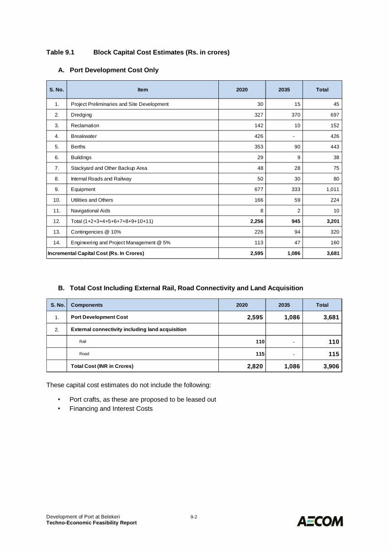
Development of Port at Belekeri 9-2Techno-Economic Feasibility Report
Table 9.1 Block Capital Cost Estimates (Rs. in crores)
A. Port Development Cost Only
B. Total Cost Including External Rail, Road Connectivity and Land Acquisition
These capital cost estimates do not include the following:
· Port crafts, as these are proposed to be leased out· Financing and Interest Costs
1. Project Preliminaries and Site Development 30 15 45
2. Dredging 327 370 697
3. Reclamation 142 10 152
4. Breakwater 426 - 426
5. Berths 353 90 443
6. Buildings 29 9 38
7. Stackyard and Other Backup Area 48 28 75
8. Internal Roads and Railway 50 30 80
9. Equipment 677 333 1,011
10. Utilities and Others 166 59 224
11. Navigational Aids 8 2 10
12. Total (1+2+3+4+5+6+7+8+9+10+11) 2,256 945 3,201
13. Contingencies @ 10% 226 94 320
14. Engineering and Project Management @ 5% 113 47 160
2,595 1,086 3,681
2020 Total
Incremental Capital Cost (Rs. In Crores)
S. No. Item 2035
S. No. Components 2020 2035 Total
1. Port Development Cost 2,595 1,086 3,681
2. External connectivity including land acquisition
Rail 110 - 110
Road 115 - 115
Total Cost (INR in Crores) 2,820 1,086 3,906
Development of Port at Belekeri 9-3Techno-Economic Feasibility Report
Operation and Maintenance Costs9.2
General9.2.1
Operation and maintenance costs have been calculated under various heads as described in thesubsequent paras.
Repair and Maintenance Costs9.2.2
The following norms have been used for estimating the annual maintenance and repair costs:
· 5% of Mechanical equipment and Electrical Works· 1% of Civil Works· 3% of Utilities and Other Works
For dredging, the actual cost based on the maintenance dredging volume estimated from modelstudies is taken into account.
Manpower Costs9.2.3
The estimated manpower for the initial phase of development is about 200 increasing to about 300 inthe master plan stage of development. The manpower costs have accordingly been calculatedconsidering the number and types of personnel deployed.
Operation Costs9.2.4
The operation costs include the fuel, water and power costs. These have been considered as below:
· Power - Rs. 4.50 per unit plus Rs. 225 per kVA of demand rate per month· Water Charges - Rs. 50 per kilolitre· Diesel - Rs. 50 per litre
The operation costs for the equipment run by electrical power have been calculated based on themaximum throughput and utilisation of the equipment. Similarly the operation cost of major equipmentlike ITVs run by diesel has been worked out based on the utilisation level for the annual throughput.Further the operation costs of the following items have been estimated as a percentage of their capitalcost, as given below:
· Diesel Driven Equipment (minor) - 5% per annum· Other Works such as Firefighting & Pollution Control - 3% per annum
Annual Incremental Operation and Maintenance Costs9.2.5
Based on the various criteria discussed above, the annual operation and maintenance cost for variousphases of development of Port at Belekeri are summarised below in Table 9.2 below:
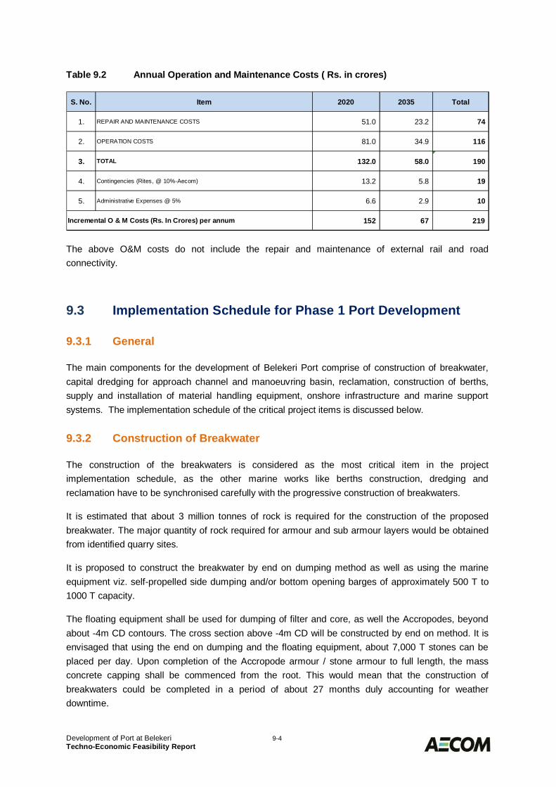
Development of Port at Belekeri 9-4Techno-Economic Feasibility Report
Table 9.2 Annual Operation and Maintenance Costs ( Rs. in crores)
The above O&M costs do not include the repair and maintenance of external rail and roadconnectivity.
Implementation Schedule for Phase 1 Port Development9.3
General9.3.1
The main components for the development of Belekeri Port comprise of construction of breakwater,capital dredging for approach channel and manoeuvring basin, reclamation, construction of berths,supply and installation of material handling equipment, onshore infrastructure and marine supportsystems. The implementation schedule of the critical project items is discussed below.
Construction of Breakwater9.3.2
The construction of the breakwaters is considered as the most critical item in the projectimplementation schedule, as the other marine works like berths construction, dredging andreclamation have to be synchronised carefully with the progressive construction of breakwaters.
It is estimated that about 3 million tonnes of rock is required for the construction of the proposedbreakwater. The major quantity of rock required for armour and sub armour layers would be obtainedfrom identified quarry sites.
It is proposed to construct the breakwater by end on dumping method as well as using the marineequipment viz. self-propelled side dumping and/or bottom opening barges of approximately 500 T to1000 T capacity.
The floating equipment shall be used for dumping of filter and core, as well the Accropodes, beyondabout -4m CD contours. The cross section above -4m CD will be constructed by end on method. It isenvisaged that using the end on dumping and the floating equipment, about 7,000 T stones can beplaced per day. Upon completion of the Accropode armour / stone armour to full length, the massconcrete capping shall be commenced from the root. This would mean that the construction ofbreakwaters could be completed in a period of about 27 months duly accounting for weatherdowntime.
S. No. Item 2020 2035 Total
1. REPAIR AND MAINTENANCE COSTS 51.0 23.2 74
2. OPERATION COSTS 81.0 34.9 116
3. TOTAL 132.0 58.0 190
4. Contingencies (Rites, @ 10%-Aecom) 13.2 5.8 19
5. Administrative Expenses @ 5% 6.6 2.9 10
Incremental O & M Costs (Rs. In Crores) per annum 152 67 219
Development of Port at Belekeri 9-5Techno-Economic Feasibility Report
Dredging and Reclamation9.3.3
The overall dredging quantity is estimated to be about 16.4 Mcum. Initially the reclamation bunds shallbe built to receive the suitable material from the dredging operations and then dredging activity cancommence in the fair weather season. While the dredging by cutter suction dredger would be limitedduring fair weather season the same using TSHD shall be carried out round the year. The overallduration of the dredging and reclamation is expected to be 22 months. However in case some rockpatches are found in the dredging area the duration will increase.
Berths9.3.4
As bulk berths are not proposed to be contiguous to the land, construction of these berths would beindependent of the dredging. However the construction of multipurpose berth having backup areawould need to be synchronised with dredging and reclamation.
Considering the berths are located a distance of about 3.1 km from shore, the construction of berthscould be either undertaken using floating equipment or by launching the gantries from the partlycompleted breakwater. The latter option is most likely as it would involve lesser downtime due toweather and relatively lower cost of construction.
The berth piling would be commenced using piling gantries installed from the completed portion of thebreakwater. The superstructure would be mainly built using precast concrete elements to avoid soffitshuttering. This would also enable the construction of superstructure on the piles already completed.The construction of berths is expected to take about 30 months.
Equipment and Onshore Development9.3.5
It is envisaged that the delivery and installation of equipment and the development of onshore workscan be carried out to match the implementation schedule of the project.
Implementation Schedule9.3.6
The construction time of Phase 1 development of Belekeri port is likely to take over 40 months. Thishas been worked out taking into account all the items of the project, the various activities involved andthe duration of each activity. The project implementation schedule for the Phase 1 Development ofBelekeri Port is shown in Table 9.3.
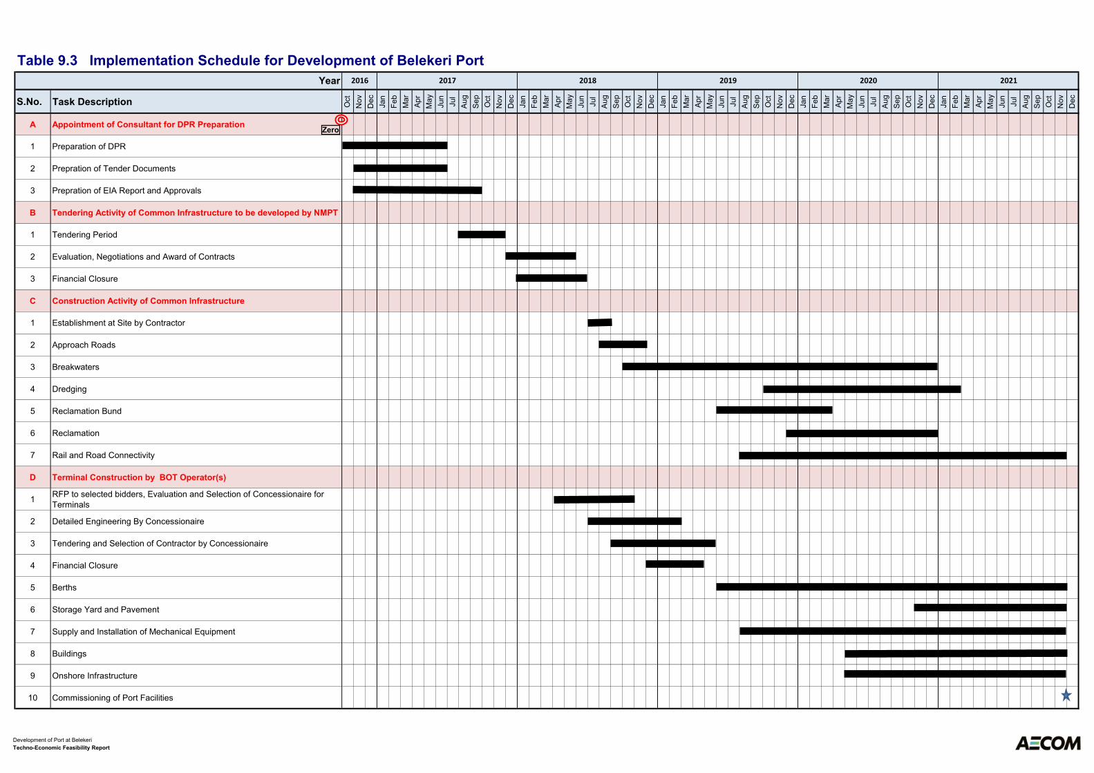
S.No. Task Description Oct
No
v
De
c
Ja
n
Fe
b
Ma
r
Ap
r
Ma
y
Ju
n
Ju
l
Au
g
Se
p
Oct
No
v
De
c
Ja
n
Fe
b
Ma
r
Ap
r
Ma
y
Ju
n
Ju
l
Au
g
Se
p
Oct
No
v
De
c
Ja
n
Fe
b
Ma
r
Ap
r
Ma
y
Ju
n
Ju
l
Au
g
Se
p
Oct
No
v
De
c
Ja
n
Fe
b
Ma
r
Ap
r
Ma
y
Ju
n
Ju
l
Au
g
Se
p
Oct
No
v
De
c
Ja
n
Fe
b
Ma
r
Ap
r
Ma
y
Ju
n
Ju
l
Au
g
Se
p
Oct
No
v
De
c
A Appointment of Consultant for DPR Preparation
1 Preparation of DPR
2 Prepration of Tender Documents
3 Prepration of EIA Report and Approvals
B Tendering Activity of Common Infrastructure to be developed by NMPT
1 Tendering Period
2 Evaluation, Negotiations and Award of Contracts
3 Financial Closure
C Construction Activity of Common Infrastructure
1 Establishment at Site by Contractor
2 Approach Roads
3 Breakwaters
4 Dredging
5 Reclamation Bund
6 Reclamation
7 Rail and Road Connectivity
D Terminal Construction by BOT Operator(s)
1RFP to selected bidders, Evaluation and Selection of Concessionaire for
Terminals
2 Detailed Engineering By Concessionaire
3 Tendering and Selection of Contractor by Concessionaire
4 Financial Closure
5 Berths
6 Storage Yard and Pavement
7 Supply and Installation of Mechanical Equipment
8 Buildings
9 Onshore Infrastructure
10 Commissioning of Port Facilities
Table 9.3 Implementation Schedule for Development of Belekeri Port
Year 2016 2017 2018 2019 2020 2021
Zero
Development of Port at Belekeri
Techno-Economic Feasibility Report
Development of Port at Belekeri 10-1Techno-Economic Feasibility Report
FINANCIAL ANALYSIS FOR ALTERNATIVE10.0MEANS OF PROJECT DEVELOPMENTAssumptions for Financial Assessment10.1
The following assumptions have been made while making the financial assessment of the project andarriving at the suitable means of project development:
· Due to the minimal incremental traffic the financials have been worked out assuming the thereis no expansion after Phase 1 development of port. However, any subsequent expansionwould improve the project viability.
· Based on the profiling of competing ports following tariff has been assumed
o Coal - Rs. 200 per tonneo Containers - Rs. 4500 per TEU
· The cost of Debt is assumed as 11% for PPP operator.
· The cost of Debt for the SPV, in case of Landlord model, is assumed at 4%.
Option 1 – By Project Proponents10.2In this option, the project shall be executed by the public sector entity, i.e., (New Mangalore Port Trustand/or State Government/SDC), who shall also arrange funds for the project financing, manage andoperate the port.
The financial analysis has been carried out considering the overall capital investment of Rs. 2820crores for Phase 1 port development. The project IRR in this scenario works out to about 11.5%.
Option 2 – Full Fledged Concession to Private Operator10.3In this option, the entire project is allocated to a private developer like in case of Mundra,Gangavaram, Krishnapatnam ports on revenue share basis.
In this case the costs towards External Rail and Road Connectivity to port and land acquisition forconnectivity and port facilities shall be borne by the government entities.
Therefore the capital investment for the private operator shall be limited to Rs. 2595 crores only.However, in this case also the project IRR for the private developer works out to about 12.4% evenafter considering that the developer does not do any revenue sharing with government.
Development of Port at Belekeri 10-2Techno-Economic Feasibility Report
Option 3 – Landlord Model10.4
In this option a Special Purpose Vehicle (SPV) shall be formed comprising of New Mangalore PortTrust and other government entities which may include Karnataka State Government, SagarmalaDevelopment Corporation etc. The exact composition of SPV and the % share of the entities could bedecided once the decision to go ahead with the project is taken. The following shall be modalities fordevelopment under this option:
1. The basic infrastructure in terms of Breakwaters, capital dredging, reclamation, access rail androad, water and power connection, harbour crafts etc. shall be arranged by SPV. Apart from that,the SPV shall also be responsible providing external rail and road connectivity to port including anyland acquisition for connectivity and port development. In addition SPV shall also be responsiblefor:
· Appointing a Harbour Master and conservator of the port.
· Navigation in the port by having qualified and licensed pilots to pilot ships with aids like tugsetc., attending to berthing and de-berthing of ships calling at the port.
· Providing and maintaining the basic infrastructure.
· Payment of lease-rent for areas leased to it and other payments to the State Government asmay be contained in the agreement.
· Furnishing management information to the appropriate authorities and administeringsubleases for the various marine terminals leased to users, terminal operators asapplicable.
2. The cargo handling terminals and associated facilities comprising of berths, stackyarddevelopment, equipment, utilities etc. will be developed with private participation on PPP mode.PPP Concessionaire would be responsible for terminal operations and maintenance and sharing ofits revenue with SPV as per the concession agreement.
In the proposed implementation model the cost split between the project proponents and the terminaloperators is estimated as below in Table 10.1:
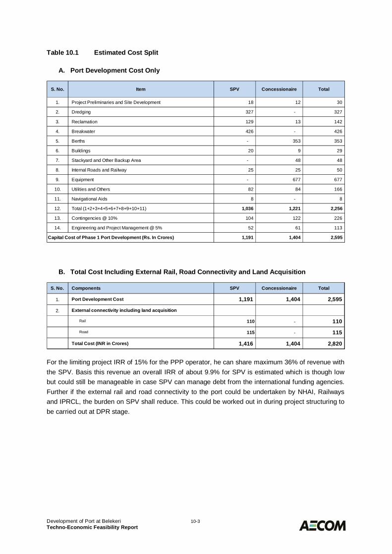
Development of Port at Belekeri 10-3Techno-Economic Feasibility Report
Table 10.1 Estimated Cost Split
A. Port Development Cost Only
B. Total Cost Including External Rail, Road Connectivity and Land Acquisition
For the limiting project IRR of 15% for the PPP operator, he can share maximum 36% of revenue withthe SPV. Basis this revenue an overall IRR of about 9.9% for SPV is estimated which is though lowbut could still be manageable in case SPV can manage debt from the international funding agencies.Further if the external rail and road connectivity to the port could be undertaken by NHAI, Railwaysand IPRCL, the burden on SPV shall reduce. This could be worked out in during project structuring tobe carried out at DPR stage.
1. Project Preliminaries and Site Development 18 12 30
2. Dredging 327 - 327
3. Reclamation 129 13 142
4. Breakwater 426 - 426
5. Berths - 353 353
6. Buildings 20 9 29
7. Stackyard and Other Backup Area - 48 48
8. Internal Roads and Railway 25 25 50
9. Equipment - 677 677
10. Utilities and Others 82 84 166
11. Navigational Aids 8 - 8
12. Total (1+2+3+4+5+6+7+8+9+10+11) 1,036 1,221 2,256
13. Contingencies @ 10% 104 122 226
14. Engineering and Project Management @ 5% 52 61 113
1,191 1,404 2,595
Total
Capital Cost of Phase 1 Port Development (Rs. In Crores)
S. No. Item SPV Concessionaire
S. No. Components SPV Concessionaire Total
1. Port Development Cost 1,191 1,404 2,595
2. External connectivity including land acquisition
Rail 110 - 110
Road 115 - 115
Total Cost (INR in Crores) 1,416 1,404 2,820
Development of Port at Belekeri 11-1Techno-Economic Feasibility Report
WAY FORWARD11.0
With the projected traffic, there is a strong case for development of port at Belekeri on landlord model.However the entire port development is dependent on the completion of Hubli Ankola rail link. It is alsosuggested that the proposed Hubli Ankola Rail link be extended till Belekeri as a single project to getsynergy and also provide competitive multi-modal transport to the destination. It is further proposedthat all efforts must be directed to get environmental clearance for this connecting rail link beforeundertaking any further study or work for the proposed port.
In case it is decided to pursue the project, the following action plan is recommended:
1. The current road blocks to the completion of development of Hubli Ankola rail need to beremoved with active participation from State and Central government.
2. An SPV for development of the port may be formed.
3. Once it is certain that Hubli Ankola rail link would be completed in a given time frame start forthe process of port development by initially appointing a consultant for preparation of detailedproject report.
4. The detailed project report shall use the present TEFR as a base document and refine itfurther by:
a. Carrying out marine geotechnical investigations
b. Real Time Ship Navigational Studies
c. Engineering of the Marine Structures, material handling system and onshoreinfrastructure to further refine the cost estimates
d. Two and three dimensional model studies for design of breakwaters.
e. Mathematical model studies on the updated layout, if any, for further optimisation.Apart from that model studies for dispersal of dredged plume at the proposed disposalsite would be needed as per the requirement of MoEF.
f. Updated financial analysis
5. Approvals from SFC/ EFC/ PIB/ PPPAC/ CCEA
6. Preparation of EIA report and approval of MoEF
7. Preparation of tender documents for Selection of contractors for the works to be undertakenby project proponents (PPT)
8. Start the construction of Breakwaters, reclamation, dredging and basic onshore infrastructure
9. Selection of Transaction Advisor and bidding for the selection of operator(s) for the terminaldevelopment
10. Terminal development works by the BOT operator
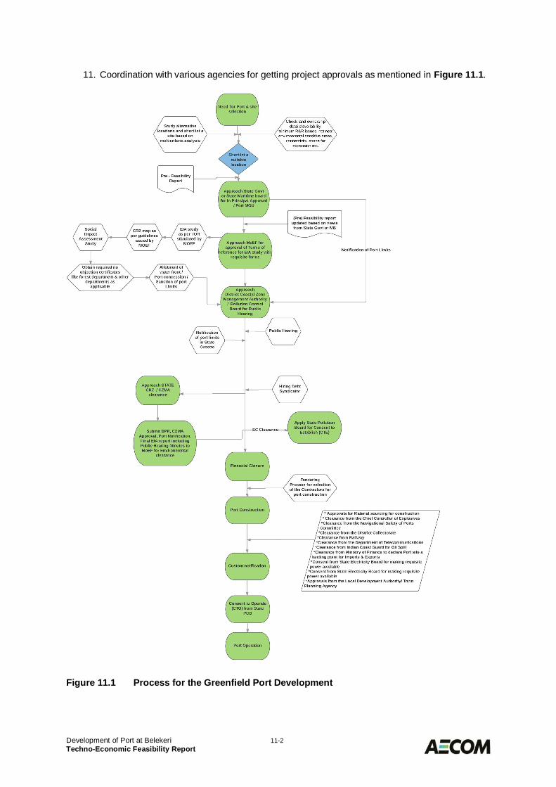
Development of Port at Belekeri 11-2Techno-Economic Feasibility Report
11. Coordination with various agencies for getting project approvals as mentioned in Figure 11.1.
Figure 11.1 Process for the Greenfield Port Development

Drawings
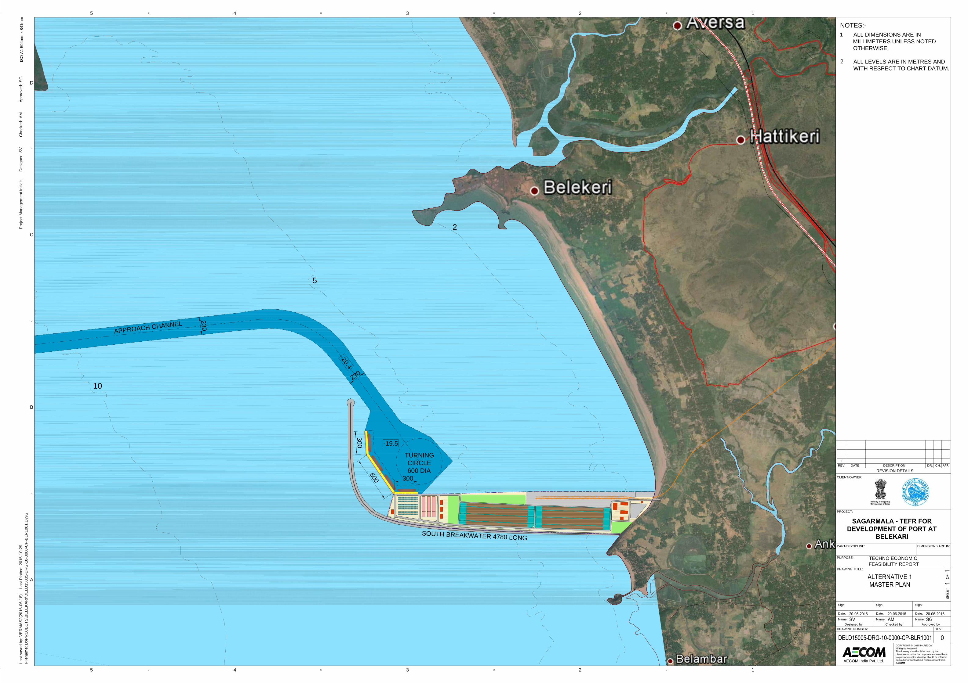
TURNINGCIRCLE600 DIA
APPROACH CHANNEL
300
600
230
230
-19.5
-20.4300
SOUTH BREAKWATER 4780 LONG
10
5
2
ISO
A1
594m
m x
841
mm
45
45
D
3 2 1
C
B
A
3 2 1
Last
sav
ed b
y: V
ERM
AS2(
2016
-06-
18)
La
st P
lotte
d: 2
015-
10-2
9Fi
lena
me:
D:\P
RO
JEC
TS\B
ELEK
ARI\D
ELD
1500
5-D
RG
-10-
0000
-CP-
BLR
1001
.DW
G
AECOM India Pvt. Ltd.
DRAWING NUMBER: REV.
DRAWING TITLE:
PURPOSE:
PART/DISCIPLINE:
PROJECT:
CLIENT/OWNER:
REVISION DETAILSREV. DATE DESCRIPTION DR. CH.
COPYRIGHT © 2015 by AECOM
All Rights ReservedThe drawing should only be used by theclient/contractor for the purpose mentioned here.No part/wholeof the drawing should be referredfrom other project without written consent fromAECOM
DIMENSIONS ARE IN:
Proj
ect M
anag
emen
t Ini
tials
:D
esig
ner:
Che
cked
:Ap
prov
ed:
SVAM
SG
SAGARMALA - TEFR FOR
DEVELOPMENT OF PORT AT
BELEKARI
Designed by Checked by Approved byName:
Date:
Sign:
Name:
Date:
Sign:
Name:
Date:
Sign:
TECHNO ECONOMICFEASIBILITY REPORT
NOTES:-ALL DIMENSIONS ARE INMILLIMETERS UNLESS NOTEDOTHERWISE.
ALL LEVELS ARE IN METRES ANDWITH RESPECT TO CHART DATUM.
1
2

TURNINGCIRCLE500 DIA
APPROACH CHANNEL
600
BULK
150
150
300
MPB
-15.4
-16.1
SOUTH BREAKWATER 4780 LONG
10
5
2
ISO
A1
594m
m x
841
mm
45
45
D
3 2 1
C
B
A
3 2 1
Last
sav
ed b
y: V
ERM
AS2(
2016
-06-
18)
La
st P
lotte
d: 2
015-
10-2
9Fi
lena
me:
D:\P
RO
JEC
TS\B
ELEK
ARI\D
ELD
1500
5-D
RG
-10-
0000
-CP-
BLR
1002
.DW
G
AECOM India Pvt. Ltd.
DRAWING NUMBER: REV.
DRAWING TITLE:
PURPOSE:
PART/DISCIPLINE:
PROJECT:
CLIENT/OWNER:
REVISION DETAILSREV. DATE DESCRIPTION DR. CH.
COPYRIGHT © 2015 by AECOM
All Rights ReservedThe drawing should only be used by theclient/contractor for the purpose mentioned here.No part/wholeof the drawing should be referredfrom other project without written consent fromAECOM
DIMENSIONS ARE IN:
Proj
ect M
anag
emen
t Ini
tials
:D
esig
ner:
Che
cked
:Ap
prov
ed:
SVAM
SG
SAGARMALA - TEFR FOR
DEVELOPMENT OF PORT AT
BELEKARI
Designed by Checked by Approved byName:
Date:
Sign:
Name:
Date:
Sign:
Name:
Date:
Sign:
TECHNO ECONOMICFEASIBILITY REPORT
NOTES:-ALL DIMENSIONS ARE INMILLIMETERS UNLESS NOTEDOTHERWISE.
ALL LEVELS ARE IN METRES ANDWITH RESPECT TO CHART DATUM.
1
2
2
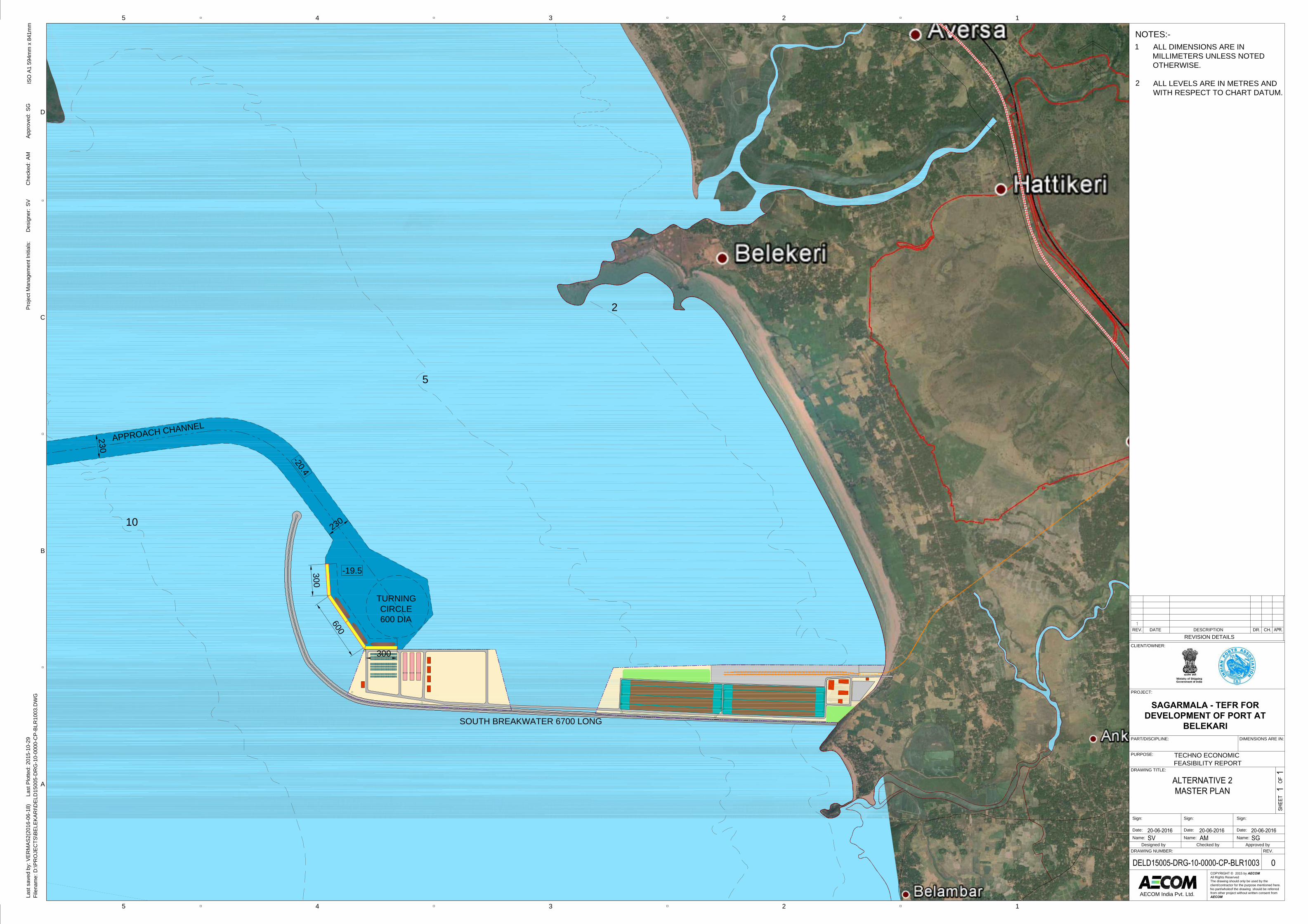
TURNINGCIRCLE600 DIA
APPROACH CHANNEL
300
600
10
5
2
-19.5
-20.4
230
230
SOUTH BREAKWATER 6700 LONG
300
ISO
A1
594m
m x
841
mm
45
45
D
3 2 1
C
B
A
3 2 1
Last
sav
ed b
y: V
ERM
AS2(
2016
-06-
18)
La
st P
lotte
d: 2
015-
10-2
9Fi
lena
me:
D:\P
RO
JEC
TS\B
ELEK
ARI\D
ELD
1500
5-D
RG
-10-
0000
-CP-
BLR
1003
.DW
G
AECOM India Pvt. Ltd.
DRAWING NUMBER: REV.
DRAWING TITLE:
PURPOSE:
PART/DISCIPLINE:
PROJECT:
CLIENT/OWNER:
REVISION DETAILSREV. DATE DESCRIPTION DR. CH.
COPYRIGHT © 2015 by AECOM
All Rights ReservedThe drawing should only be used by theclient/contractor for the purpose mentioned here.No part/wholeof the drawing should be referredfrom other project without written consent fromAECOM
DIMENSIONS ARE IN:
Proj
ect M
anag
emen
t Ini
tials
:D
esig
ner:
Che
cked
:Ap
prov
ed:
SVAM
SG
SAGARMALA - TEFR FOR
DEVELOPMENT OF PORT AT
BELEKARI
Designed by Checked by Approved byName:
Date:
Sign:
Name:
Date:
Sign:
Name:
Date:
Sign:
TECHNO ECONOMICFEASIBILITY REPORT
NOTES:-ALL DIMENSIONS ARE INMILLIMETERS UNLESS NOTEDOTHERWISE.
ALL LEVELS ARE IN METRES ANDWITH RESPECT TO CHART DATUM.
1
2
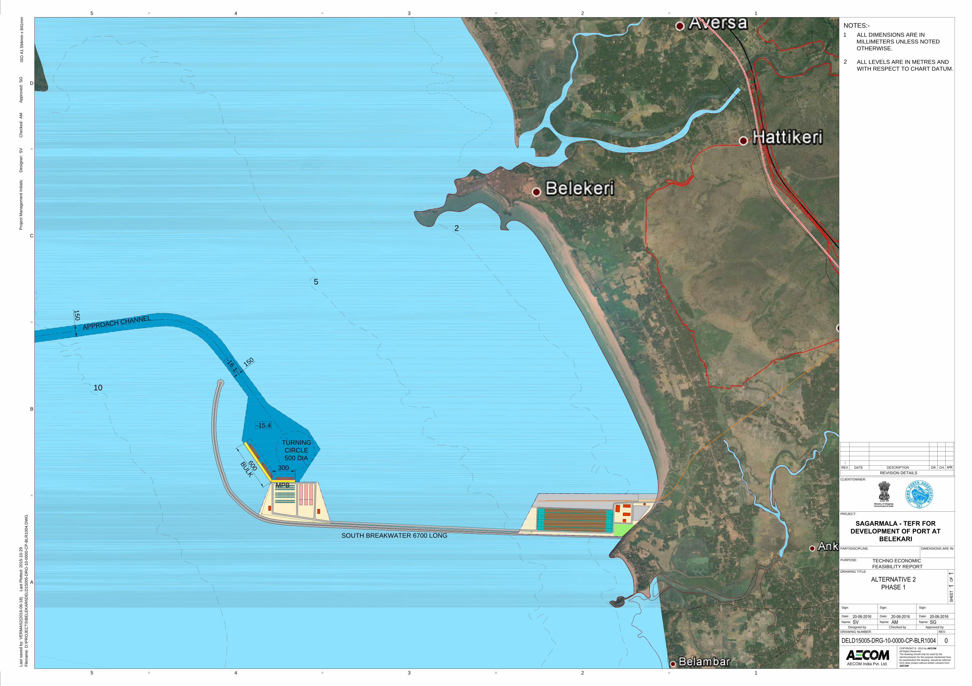
10
5
TURNINGCIRCLE500 DIA
APPROACH CHANNEL
150
150
2
300
MPB
-15.4
-16.1
600
BULK
SOUTH BREAKWATER 6700 LONG
ISO
A1
594m
m x
841
mm
45
45
D
3 2 1
C
B
A
3 2 1
Last
sav
ed b
y: V
ERM
AS2(
2016
-06-
18)
La
st P
lotte
d: 2
015-
10-2
9Fi
lena
me:
D:\P
RO
JEC
TS\B
ELEK
ARI\D
ELD
1500
5-D
RG
-10-
0000
-CP-
BLR
1004
.DW
G
AECOM India Pvt. Ltd.
DRAWING NUMBER: REV.
DRAWING TITLE:
PURPOSE:
PART/DISCIPLINE:
PROJECT:
CLIENT/OWNER:
REVISION DETAILSREV. DATE DESCRIPTION DR. CH.
COPYRIGHT © 2015 by AECOM
All Rights ReservedThe drawing should only be used by theclient/contractor for the purpose mentioned here.No part/wholeof the drawing should be referredfrom other project without written consent fromAECOM
DIMENSIONS ARE IN:
Proj
ect M
anag
emen
t Ini
tials
:D
esig
ner:
Che
cked
:Ap
prov
ed:
SVAM
SG
SAGARMALA - TEFR FOR
DEVELOPMENT OF PORT AT
BELEKARI
Designed by Checked by Approved byName:
Date:
Sign:
Name:
Date:
Sign:
Name:
Date:
Sign:
TECHNO ECONOMICFEASIBILITY REPORT
NOTES:-ALL DIMENSIONS ARE INMILLIMETERS UNLESS NOTEDOTHERWISE.
ALL LEVELS ARE IN METRES ANDWITH RESPECT TO CHART DATUM.
1
2

TURNINGCIRCLE600 DIA
APPROACH CHANNEL
300
600
230
230
-19.5
-20.4300
SOUTH BREAKWATER 4780 LONG
10
5
2
ISO
A1
594m
m x
841
mm
45
45
D
3 2 1
C
B
A
3 2 1
Last
sav
ed b
y: V
ERM
AS2(
2016
-06-
18)
La
st P
lotte
d: 2
015-
10-2
9Fi
lena
me:
D:\P
RO
JEC
TS\B
ELEK
ARI\D
ELD
1500
5-D
RG
-10-
0000
-CP-
BLR
1005
.DW
G
AECOM India Pvt. Ltd.
DRAWING NUMBER: REV.
DRAWING TITLE:
PURPOSE:
PART/DISCIPLINE:
PROJECT:
CLIENT/OWNER:
REVISION DETAILSREV. DATE DESCRIPTION DR. CH.
COPYRIGHT © 2015 by AECOM
All Rights ReservedThe drawing should only be used by theclient/contractor for the purpose mentioned here.No part/wholeof the drawing should be referredfrom other project without written consent fromAECOM
DIMENSIONS ARE IN:
Proj
ect M
anag
emen
t Ini
tials
:D
esig
ner:
Che
cked
:Ap
prov
ed:
SVAM
SG
SAGARMALA - TEFR FOR
DEVELOPMENT OF PORT AT
BELEKARI
Designed by Checked by Approved byName:
Date:
Sign:
Name:
Date:
Sign:
Name:
Date:
Sign:
TECHNO ECONOMICFEASIBILITY REPORT
NOTES:-ALL DIMENSIONS ARE INMILLIMETERS UNLESS NOTEDOTHERWISE.
ALL LEVELS ARE IN METRES ANDWITH RESPECT TO CHART DATUM.
1
2
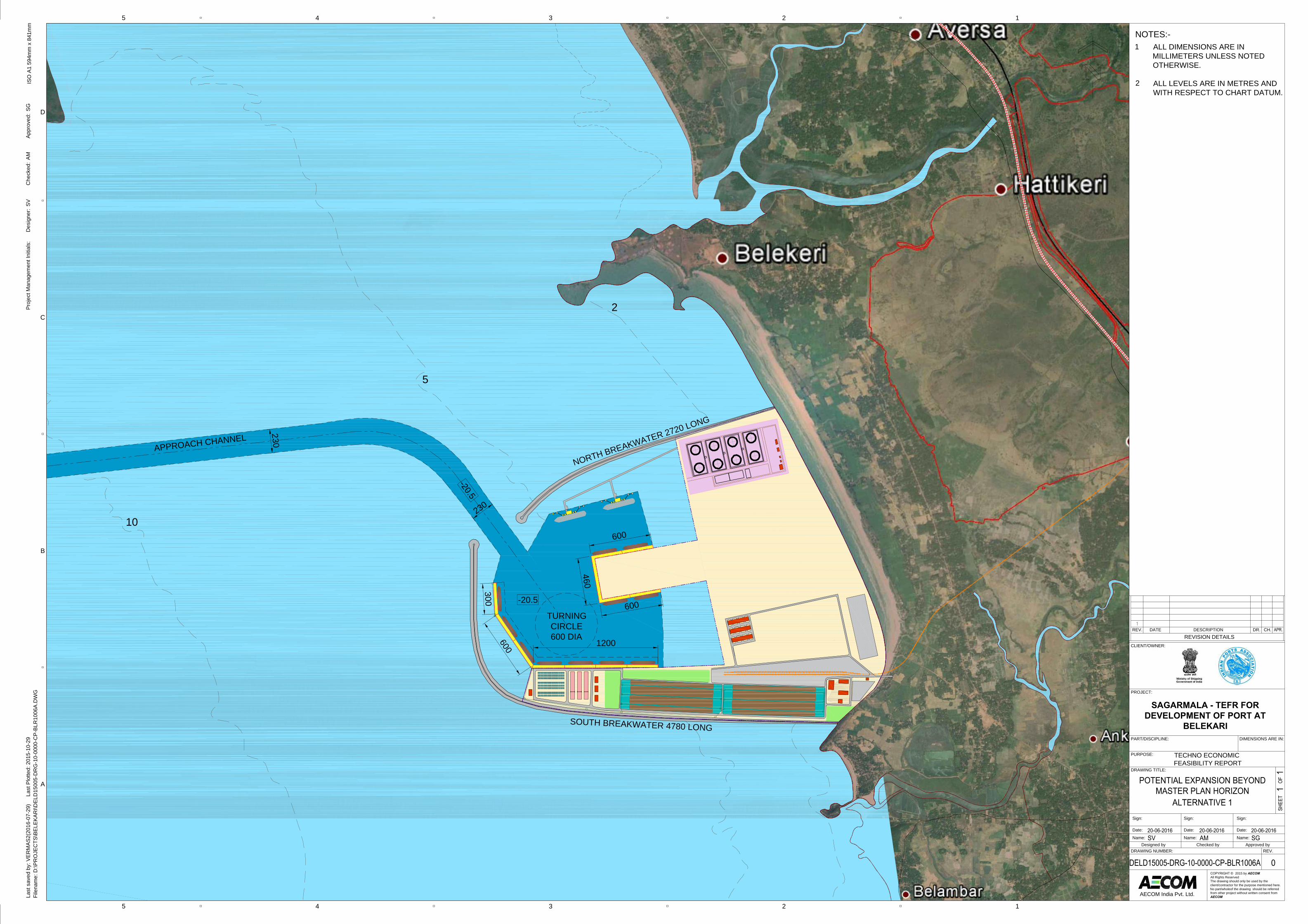
TURNINGCIRCLE600 DIA
APPROACH CHANNEL
1200600
230
230
-20.5
-20.5
SOUTH BREAKWATER 4780 LONG
NORTH BREAKWATER 2720 LONG
600
600
460
300
10
5
2
ISO
A1
594m
m x
841
mm
45
45
D
3 2 1
C
B
A
3 2 1
Last
sav
ed b
y: V
ERM
AS2(
2016
-07-
29)
La
st P
lotte
d: 2
015-
10-2
9Fi
lena
me:
D:\P
RO
JEC
TS\B
ELEK
ARI\D
ELD
1500
5-D
RG
-10-
0000
-CP-
BLR
1006
A.D
WG
AECOM India Pvt. Ltd.
DRAWING NUMBER: REV.
DRAWING TITLE:
PURPOSE:
PART/DISCIPLINE:
PROJECT:
CLIENT/OWNER:
REVISION DETAILSREV. DATE DESCRIPTION DR. CH.
COPYRIGHT © 2015 by AECOM
All Rights ReservedThe drawing should only be used by theclient/contractor for the purpose mentioned here.No part/wholeof the drawing should be referredfrom other project without written consent fromAECOM
DIMENSIONS ARE IN:
Proj
ect M
anag
emen
t Ini
tials
:D
esig
ner:
Che
cked
:Ap
prov
ed:
SVAM
SG
SAGARMALA - TEFR FOR
DEVELOPMENT OF PORT AT
BELEKARI
Designed by Checked by Approved byName:
Date:
Sign:
Name:
Date:
Sign:
Name:
Date:
Sign:
TECHNO ECONOMICFEASIBILITY REPORT
NOTES:-ALL DIMENSIONS ARE INMILLIMETERS UNLESS NOTEDOTHERWISE.
ALL LEVELS ARE IN METRES ANDWITH RESPECT TO CHART DATUM.
1
2
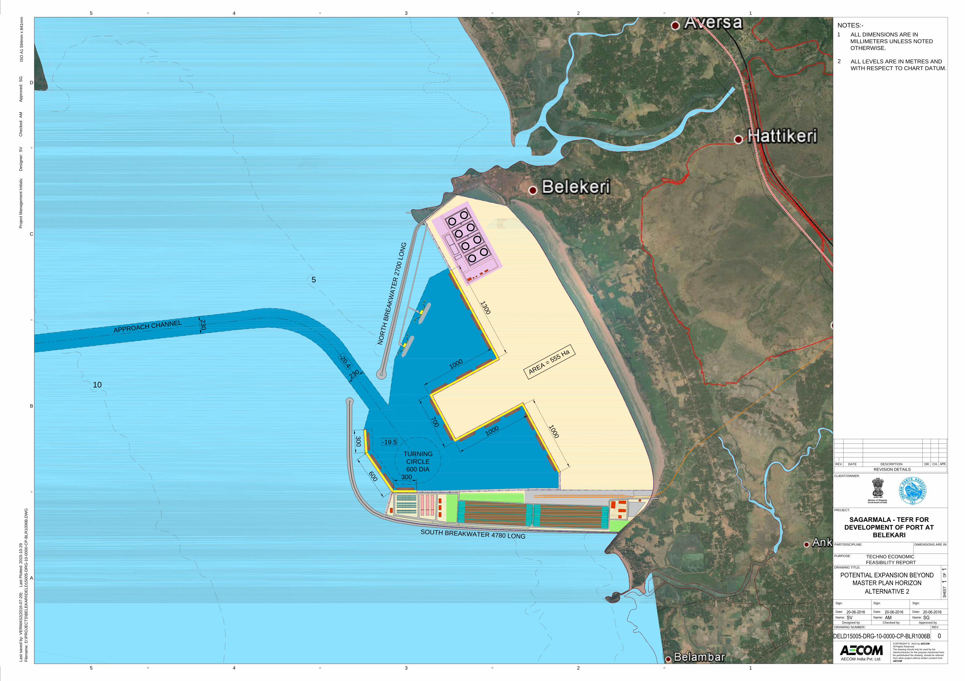
TURNINGCIRCLE600 DIA
APPROACH CHANNEL
300
600
230
230
-19.5
-20.4300
SOUTH BREAKWATER 4780 LONG
10
5
1000
1000
700 1000
1300
NO
RTH
BR
EAKW
ATER
270
0 LO
NG
ISO
A1
594m
m x
841
mm
45
45
D
3 2 1
C
B
A
3 2 1
Last
sav
ed b
y: V
ERM
AS2(
2016
-07-
29)
La
st P
lotte
d: 2
015-
10-2
9Fi
lena
me:
D:\P
RO
JEC
TS\B
ELEK
ARI\D
ELD
1500
5-D
RG
-10-
0000
-CP-
BLR
1006
B.D
WG
AECOM India Pvt. Ltd.
DRAWING NUMBER: REV.
DRAWING TITLE:
PURPOSE:
PART/DISCIPLINE:
PROJECT:
CLIENT/OWNER:
REVISION DETAILSREV. DATE DESCRIPTION DR. CH.
COPYRIGHT © 2015 by AECOM
All Rights ReservedThe drawing should only be used by theclient/contractor for the purpose mentioned here.No part/wholeof the drawing should be referredfrom other project without written consent fromAECOM
DIMENSIONS ARE IN:
Proj
ect M
anag
emen
t Ini
tials
:D
esig
ner:
Che
cked
:Ap
prov
ed:
SVAM
SG
SAGARMALA - TEFR FOR
DEVELOPMENT OF PORT AT
BELEKARI
Designed by Checked by Approved byName:
Date:
Sign:
Name:
Date:
Sign:
Name:
Date:
Sign:
TECHNO ECONOMICFEASIBILITY REPORT
NOTES:-ALL DIMENSIONS ARE INMILLIMETERS UNLESS NOTEDOTHERWISE.
ALL LEVELS ARE IN METRES ANDWITH RESPECT TO CHART DATUM.
1
2
AREA = 555 Ha
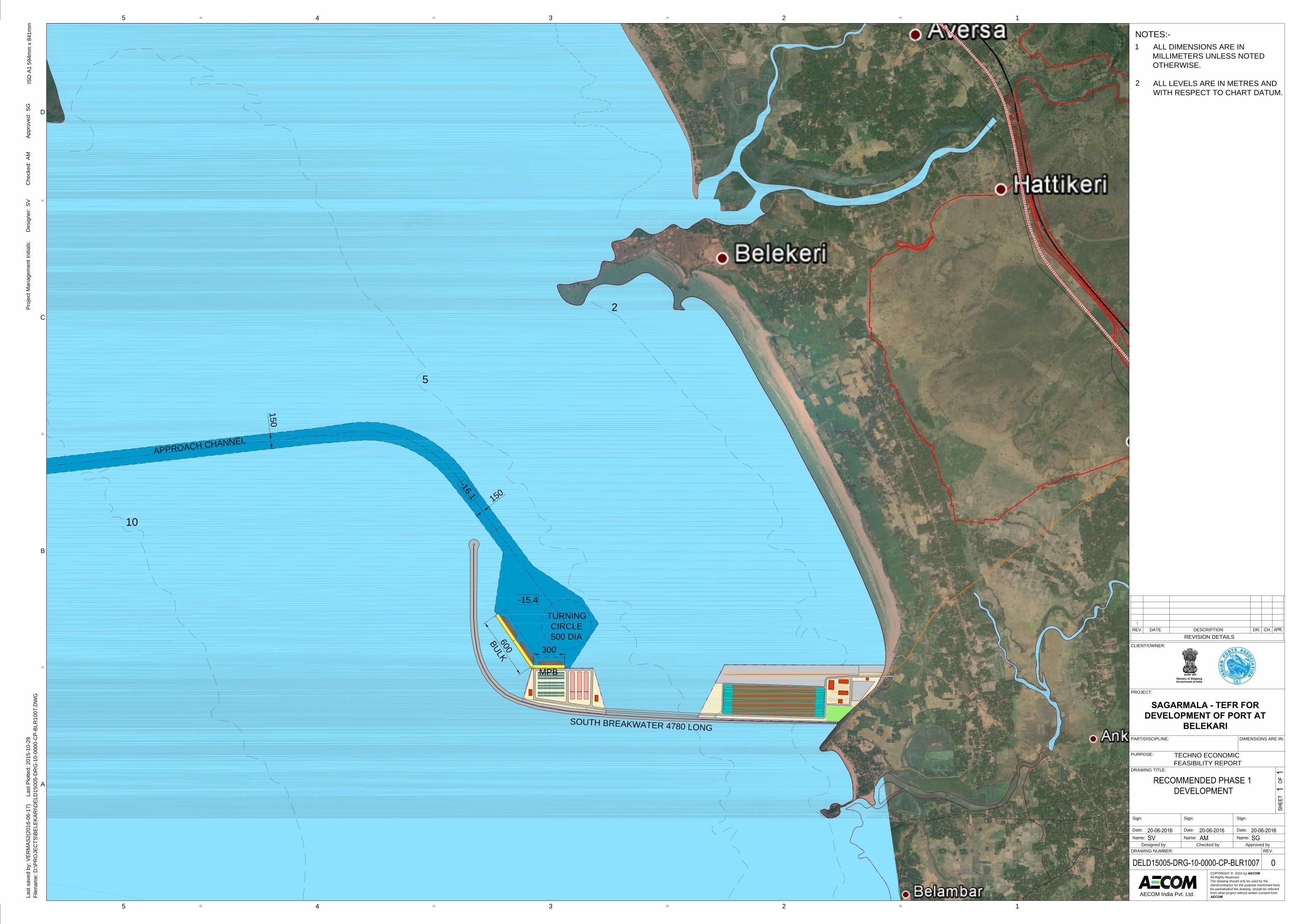
TURNINGCIRCLE500 DIA
APPROACH CHANNEL
600
BULK
150
150
300
MPB
-15.4
-16.1
SOUTH BREAKWATER 4780 LONG
10
5
2
ISO
A1
594m
m x
841
mm
45
45
D
3 2 1
C
B
A
3 2 1
Last
sav
ed b
y: V
ERM
AS2(
2016
-06-
17)
La
st P
lotte
d: 2
015-
10-2
9Fi
lena
me:
D:\P
RO
JEC
TS\B
ELEK
ARI\D
ELD
1500
5-D
RG
-10-
0000
-CP-
BLR
1007
.DW
G
AECOM India Pvt. Ltd.
DRAWING NUMBER: REV.
DRAWING TITLE:
PURPOSE:
PART/DISCIPLINE:
PROJECT:
CLIENT/OWNER:
REVISION DETAILSREV. DATE DESCRIPTION DR. CH.
COPYRIGHT © 2015 by AECOM
All Rights ReservedThe drawing should only be used by theclient/contractor for the purpose mentioned here.No part/wholeof the drawing should be referredfrom other project without written consent fromAECOM
DIMENSIONS ARE IN:
Proj
ect M
anag
emen
t Ini
tials
:D
esig
ner:
Che
cked
:Ap
prov
ed:
SVAM
SG
SAGARMALA - TEFR FOR
DEVELOPMENT OF PORT AT
BELEKARI
Designed by Checked by Approved byName:
Date:
Sign:
Name:
Date:
Sign:
Name:
Date:
Sign:
TECHNO ECONOMICFEASIBILITY REPORT
NOTES:-ALL DIMENSIONS ARE INMILLIMETERS UNLESS NOTEDOTHERWISE.
ALL LEVELS ARE IN METRES ANDWITH RESPECT TO CHART DATUM.
1
2
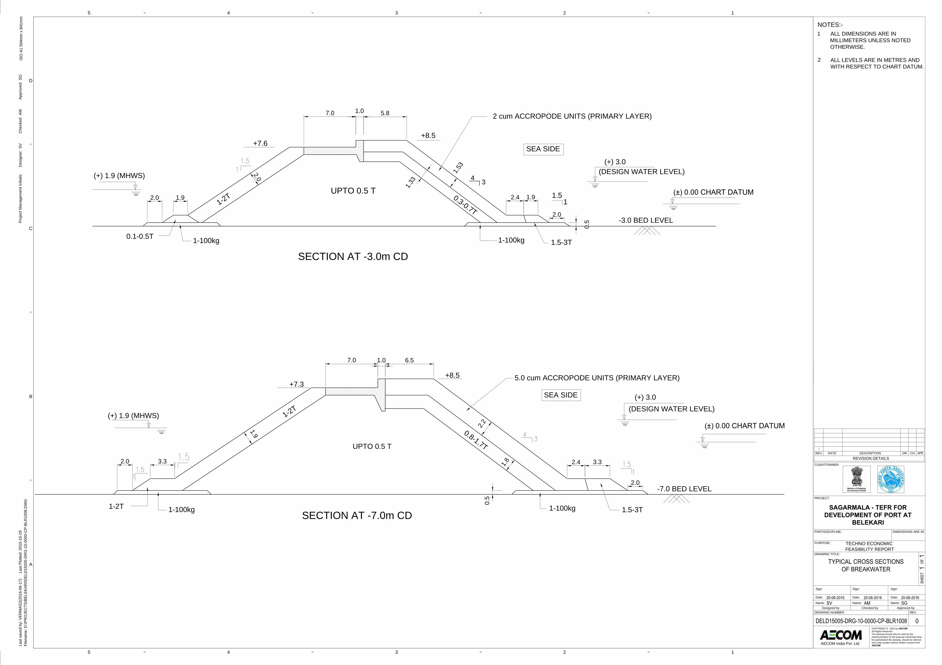
UPTO 0.5 T1-2T 0.3-0.7T
+8.5
-3.0 BED LEVEL
1.5-3T1-100kg
0.5
1.51
2.0
0.1-0.5T
(+) 3.0(DESIGN WATER LEVEL)
+7.6
2 cum ACCROPODE UNITS (PRIMARY LAYER)
(+) 1.9 (MHWS)
(±) 0.00 CHART DATUM
1-100kg
SECTION AT -3.0m CD
7.0 1.0 5.8
1.9 2.4 1.92.0
1.53
1.33
SEA SIDE
34
UPTO 0.5 T
1-2T
0.8-1.7T
+8.5
-7.0 BED LEVEL
1.5-3T1-100kg
0.5
2.0
1-2T
+7.35.0 cum ACCROPODE UNITS (PRIMARY LAYER)
SEA SIDE
2.43.3
1-100kg
7.0 1.0 6.5
SECTION AT -7.0m CD
(+) 3.0(DESIGN WATER LEVEL)
(+) 1.9 (MHWS)(±) 0.00 CHART DATUM
3.32.0
1.9
2.2
1.8
2.0
ISO
A1
594m
m x
841
mm
45
45
D
3 2 1
C
B
A
3 2 1
Last
sav
ed b
y: V
ERM
AS2(
2016
-06-
17)
La
st P
lotte
d: 2
015-
10-2
9Fi
lena
me:
D:\P
RO
JEC
TS\B
ELEK
ARI\D
ELD
1500
5-D
RG
-10-
0000
-CP-
BLR
1008
.DW
G
AECOM India Pvt. Ltd.
DRAWING NUMBER: REV.
DRAWING TITLE:
PURPOSE:
PART/DISCIPLINE:
PROJECT:
CLIENT/OWNER:
REVISION DETAILSREV. DATE DESCRIPTION DR. CH.
COPYRIGHT © 2015 by AECOM
All Rights ReservedThe drawing should only be used by theclient/contractor for the purpose mentioned here.No part/wholeof the drawing should be referredfrom other project without written consent fromAECOM
DIMENSIONS ARE IN:
Proj
ect M
anag
emen
t Ini
tials
:D
esig
ner:
Che
cked
:Ap
prov
ed:
SVAM
SG
SAGARMALA - TEFR FOR
DEVELOPMENT OF PORT AT
BELEKARI
Designed by Checked by Approved byName:
Date:
Sign:
Name:
Date:
Sign:
Name:
Date:
Sign:
TECHNO ECONOMICFEASIBILITY REPORT
NOTES:-ALL DIMENSIONS ARE INMILLIMETERS UNLESS NOTEDOTHERWISE.
ALL LEVELS ARE IN METRES ANDWITH RESPECT TO CHART DATUM.
1
2
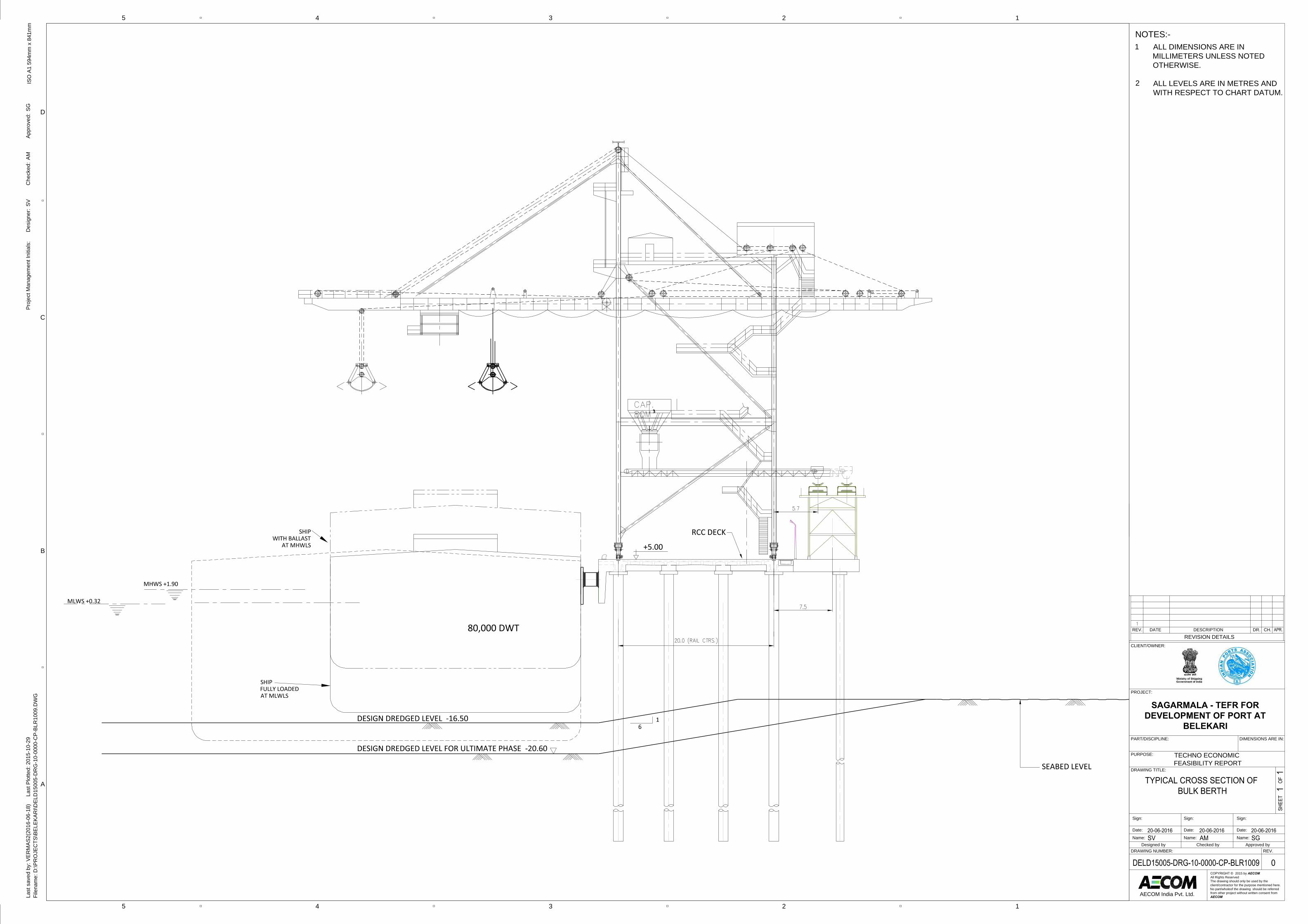
NOTES:-ALL DIMENSIONS ARE INMILLIMETERS UNLESS NOTEDOTHERWISE.
ALL LEVELS ARE IN METRES ANDWITH RESPECT TO CHART DATUM.
1
2ISO
A1
594m
m x
841
mm
45
45
D
3 2 1
C
B
A
3 2 1
Last
sav
ed b
y: V
ERM
AS2(
2016
-06-
18)
La
st P
lotte
d: 2
015-
10-2
9Fi
lena
me:
D:\P
RO
JEC
TS\B
ELEK
ARI\D
ELD
1500
5-D
RG
-10-
0000
-CP-
BLR
1009
.DW
G
AECOM India Pvt. Ltd.
DRAWING NUMBER: REV.
DRAWING TITLE:
PURPOSE:
PART/DISCIPLINE:
PROJECT:
CLIENT/OWNER:
REVISION DETAILSREV. DATE DESCRIPTION DR. CH.
COPYRIGHT © 2015 by AECOM
All Rights ReservedThe drawing should only be used by theclient/contractor for the purpose mentioned here.No part/wholeof the drawing should be referredfrom other project without written consent fromAECOM
DIMENSIONS ARE IN:
Proj
ect M
anag
emen
t Ini
tials
:D
esig
ner:
Che
cked
:Ap
prov
ed:
SVAM
SG
SAGARMALA - TEFR FOR
DEVELOPMENT OF PORT AT
BELEKARI
Designed by Checked by Approved byName:
Date:
Sign:
Name:
Date:
Sign:
Name:
Date:
Sign:
TECHNO ECONOMICFEASIBILITY REPORT
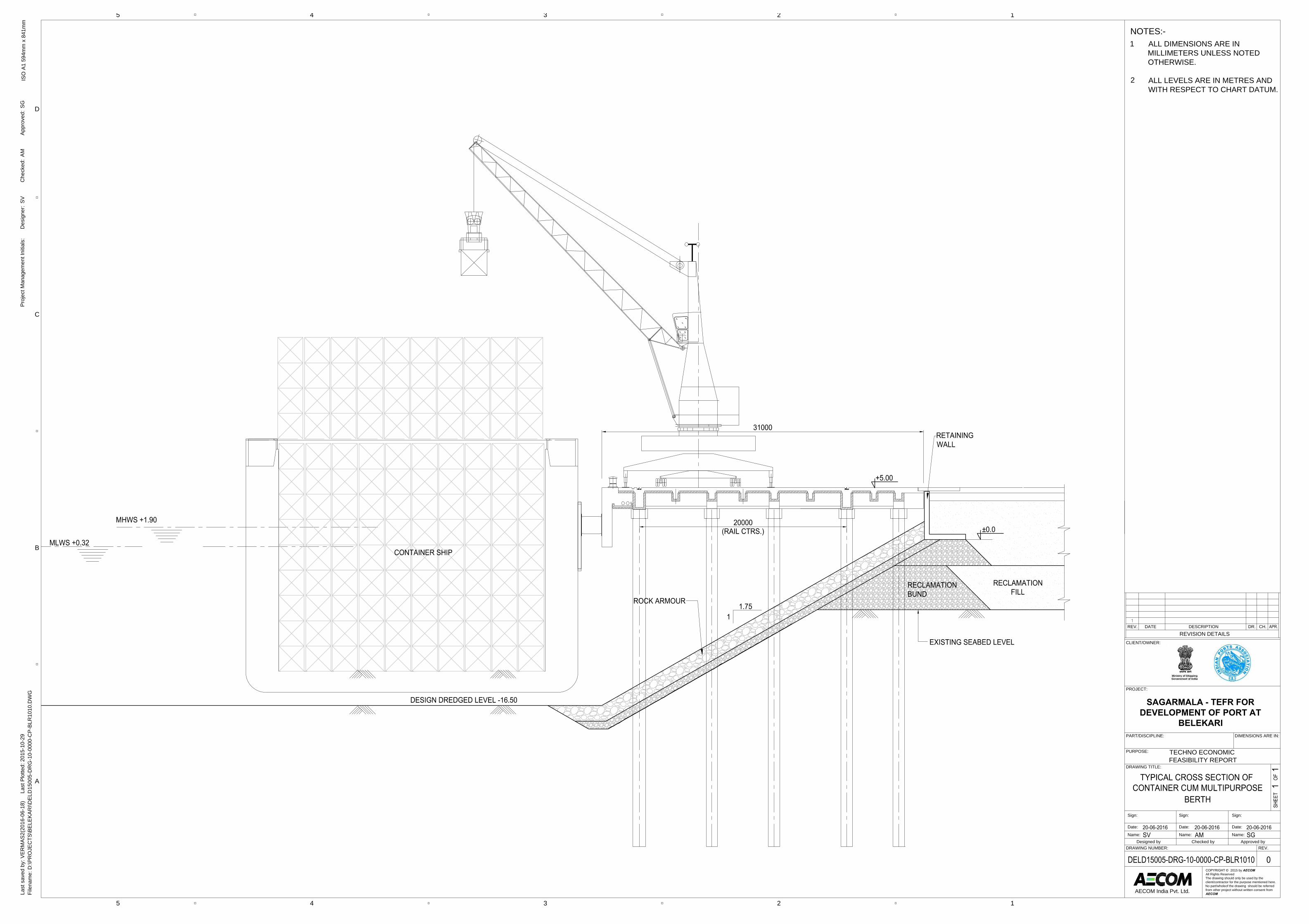
ISO
A1
594m
m x
841
mm
45
45
D
3 2 1
C
B
A
3 2 1
Last
sav
ed b
y: V
ERM
AS2(
2016
-06-
18)
La
st P
lotte
d: 2
015-
10-2
9Fi
lena
me:
D:\P
RO
JEC
TS\B
ELEK
ARI\D
ELD
1500
5-D
RG
-10-
0000
-CP-
BLR
1010
.DW
G
AECOM India Pvt. Ltd.
DRAWING NUMBER: REV.
DRAWING TITLE:
PURPOSE:
PART/DISCIPLINE:
PROJECT:
CLIENT/OWNER:
REVISION DETAILSREV. DATE DESCRIPTION DR. CH.
COPYRIGHT © 2015 by AECOM
All Rights ReservedThe drawing should only be used by theclient/contractor for the purpose mentioned here.No part/wholeof the drawing should be referredfrom other project without written consent fromAECOM
DIMENSIONS ARE IN:
Proj
ect M
anag
emen
t Ini
tials
:D
esig
ner:
Che
cked
:Ap
prov
ed:
SVAM
SG
SAGARMALA - TEFR FOR
DEVELOPMENT OF PORT AT
BELEKARI
Designed by Checked by Approved byName:
Date:
Sign:
Name:
Date:
Sign:
Name:
Date:
Sign:
TECHNO ECONOMICFEASIBILITY REPORT
NOTES:-ALL DIMENSIONS ARE INMILLIMETERS UNLESS NOTEDOTHERWISE.
ALL LEVELS ARE IN METRES ANDWITH RESPECT TO CHART DATUM.
1
2
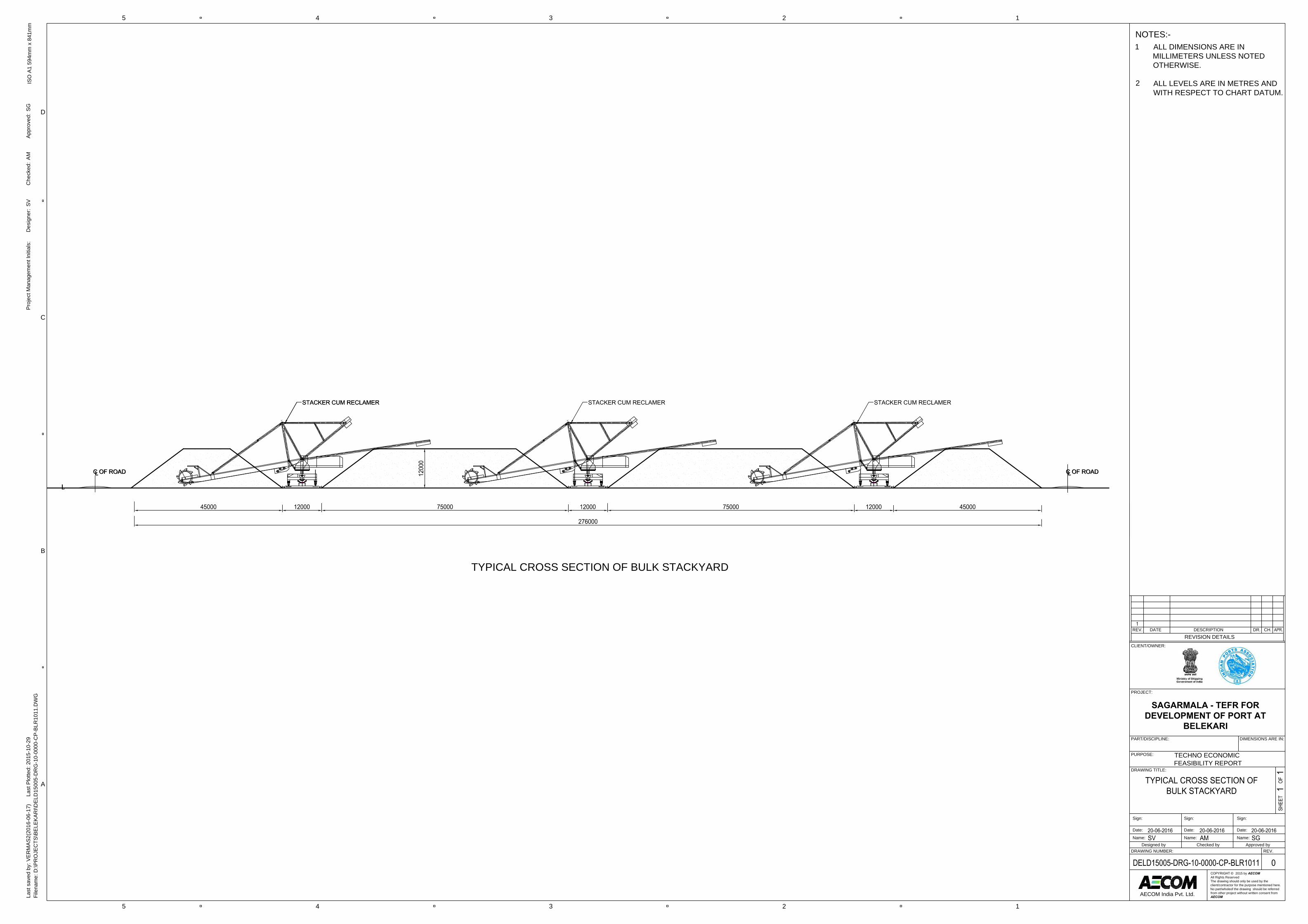
ISO
A1
594m
m x
841
mm
45
45
D
3 2 1
C
B
A
3 2 1
Last
sav
ed b
y: V
ERM
AS2(
2016
-06-
17)
La
st P
lotte
d: 2
015-
10-2
9Fi
lena
me:
D:\P
RO
JEC
TS\B
ELEK
ARI\D
ELD
1500
5-D
RG
-10-
0000
-CP-
BLR
1011
.DW
G
AECOM India Pvt. Ltd.
DRAWING NUMBER: REV.
DRAWING TITLE:
PURPOSE:
PART/DISCIPLINE:
PROJECT:
CLIENT/OWNER:
REVISION DETAILSREV. DATE DESCRIPTION DR. CH.
COPYRIGHT © 2015 by AECOM
All Rights ReservedThe drawing should only be used by theclient/contractor for the purpose mentioned here.No part/wholeof the drawing should be referredfrom other project without written consent fromAECOM
DIMENSIONS ARE IN:
Proj
ect M
anag
emen
t Ini
tials
:D
esig
ner:
Che
cked
:Ap
prov
ed:
SVAM
SG
SAGARMALA - TEFR FOR
DEVELOPMENT OF PORT AT
BELEKARI
Designed by Checked by Approved byName:
Date:
Sign:
Name:
Date:
Sign:
Name:
Date:
Sign:
TECHNO ECONOMICFEASIBILITY REPORT
NOTES:-ALL DIMENSIONS ARE INMILLIMETERS UNLESS NOTEDOTHERWISE.
ALL LEVELS ARE IN METRES ANDWITH RESPECT TO CHART DATUM.
1
2
TYPICAL CROSS SECTION OF BULK STACKYARD
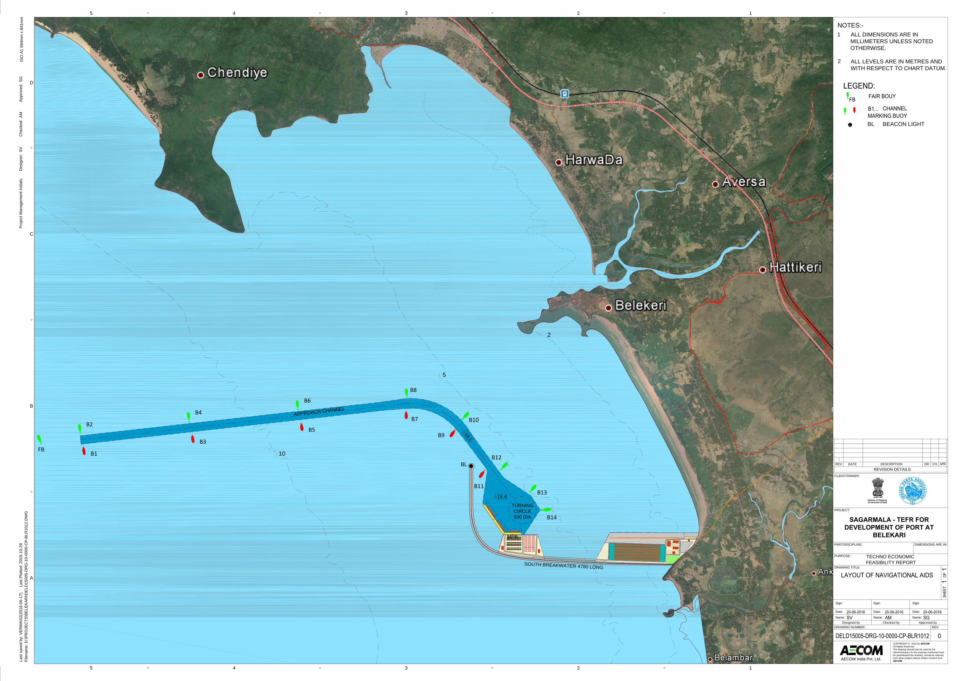
TURNINGCIRCLE500 DIA
APPROACH CHANNEL
MPB
-15.4-16.1
SOUTH BREAKWATER 4780 LONG
10
5
2
FBB1
B2
B3
B4
B5
B6
B7
B8
B9
B10
B12
B11B13
B14
BL
ISO
A1
594m
m x
841
mm
45
45
D
3 2 1
C
B
A
3 2 1
Last
sav
ed b
y: V
ERM
AS2(
2016
-06-
17)
La
st P
lotte
d: 2
015-
10-2
9Fi
lena
me:
D:\P
RO
JEC
TS\B
ELEK
ARI\D
ELD
1500
5-D
RG
-10-
0000
-CP-
BLR
1012
.DW
G
AECOM India Pvt. Ltd.
DRAWING NUMBER: REV.
DRAWING TITLE:
PURPOSE:
PART/DISCIPLINE:
PROJECT:
CLIENT/OWNER:
REVISION DETAILSREV. DATE DESCRIPTION DR. CH.
COPYRIGHT © 2015 by AECOM
All Rights ReservedThe drawing should only be used by theclient/contractor for the purpose mentioned here.No part/wholeof the drawing should be referredfrom other project without written consent fromAECOM
DIMENSIONS ARE IN:
Proj
ect M
anag
emen
t Ini
tials
:D
esig
ner:
Che
cked
:Ap
prov
ed:
SVAM
SG
SAGARMALA - TEFR FOR
DEVELOPMENT OF PORT AT
BELEKARI
Designed by Checked by Approved byName:
Date:
Sign:
Name:
Date:
Sign:
Name:
Date:
Sign:
TECHNO ECONOMICFEASIBILITY REPORT
NOTES:-ALL DIMENSIONS ARE INMILLIMETERS UNLESS NOTEDOTHERWISE.
ALL LEVELS ARE IN METRES ANDWITH RESPECT TO CHART DATUM.
1
2
FB
BL BEACON LIGHT
Related Documents