Hanning Li 1 , Yasmine Ammar 2 3 , Yaodong Wang 2 , Vinol Rego 3 , David Swailes 3 , Vida Sharifi 1 , Tony Roskilly 2 1 Department of Chemical and Biological Engineering, University of Sheffield, United Kingdom 2 Swan Centre for Energy Research, Newcastle University, Newcastle Upon Tyne, UK 3 School of Mechanical and Systems Engineering, Newcastle University, United Kingdom PRO-TEM Special Session on Thermal Energy Management: Energy System & Efficiency Improvement Techno-economic feasibility of sorption chillers coupled to humidification dehumidification desalination process for low grade heat recovery

Welcome message from author
This document is posted to help you gain knowledge. Please leave a comment to let me know what you think about it! Share it to your friends and learn new things together.
Transcript

Hanning Li1, Yasmine Ammar 2 3, Yaodong Wang2, Vinol Rego 3, David Swailes 3, Vida Sharifi 1, Tony Roskilly 2
1 Department of Chemical and Biological Engineering, University of Sheffield, United Kingdom
2 Swan Centre for Energy Research, Newcastle University, Newcastle Upon Tyne, UK
3 School of Mechanical and Systems Engineering, Newcastle University, United Kingdom
PRO-TEM Special Session on Thermal Energy Management: Energy System & Efficiency Improvement
Techno-economic feasibility of sorption chillers coupled to humidification dehumidification
desalination process for low grade heat recovery

OVERVIEW
• Aims and objectives
• Case Study: Low-grade heat (LGH) source
• Description of humification-dehumidification
process
• Process design
• Results and discussions
• Conclusions

Aims and Objectives
• Investigation of HDAC process (Humidification –
Dehumification coupled with an Absorption
Chiller) for desalination
• Utilising LGH with temperature between 50 °C
and 90 °C
• Process description and two designs
• Evaluation: capital and operational costs

Case Study: Low-grade heat source
• LGH: temperature 50 °C – 90 °C
• An integrated Pulp and board mill producing over
150,000 tonnes of product from virgin timber was
chosen.
• It is equipped with a CHP plant which supplies the
plant with all its steam and most of its electricity
requirements.
• 20 million litres of water at temperature in excess
of 35°C is discharged into the sea daily.

Case Study: Low-grade heat source
• Air & exhaust gas with temperatures 60 - 110 °C;
mass flow rate 150 kg/s
• Effluent water with temperature of 47 °C; mass
flow rate 86 kg/s.
• The large quantity of LGH located on the coast.
• Cycle tempo software developed by Delft University
was used for simulation of water production in the
HD process.
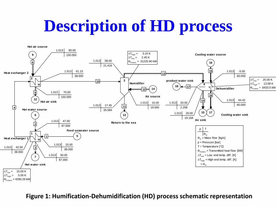
Description of HD process
Tlow = 25.00 K
Thigh = 13.58 K
H,trans = 6433.5 kW
Thigh = 3.15 K
Tlow = 2.45 K
H,trans = 31225.90 kW
Tlow = 15.00 K
Thigh = 5.00 K
H,trans = 4290.29 kW
1.013 20.00
2.258
1717
1.013 44.42
60.000
1616
1.013 -5.00
60.000
1515
1.013 20.00
19.158
1414
1.013 58.00
21.416
1313
1.013 15.00
19.000
1212
1.013 17.45
35.584
1111
1.013 61.15
38.000
1010
1.013 70.00
150.000
99
1.013 90.00
150.000
66
1.013 42.00
38.000
44
1.013 30.00
87.000
33
1.013 47.00
87.00022
1.013 15.00
38.000
11
18
17
16
15
14
13
12
9
7
6
5
4
32
H
1
H
product water sink
Air sinkReturn to the sea
Hot air sink
Hot water source
Air source
Cooling water sink
Cooling water source
Hot air source
Feed seawater source
Hot water sink
Heat exchanger 1
Heat exchanger 2
Humidifier
Dehumidifier
p T
m
m = Mass flow [kg/s]
p = Pressure [bar]
T = Temperature [°C]
H,trans = Transmitted heat f low [kW]
Tlow = Low end temp. diff. [K]
Thigh = High end temp. diff. [K]
� = m
Figure 1: Humification-Dehumidification (HD) process schematic representation

Description of the process
Figure 2 Flow diagram of HDAC-SAV (Humidification-Dehumidification coupled with absorption chiller – Superheated Ammonia Vapour)

Description of the process
Figure 3 Flow diagram of HDAC-APC (Humidification-Dehumidification coupled with absorption chiller - Ammonia Phase Change)

Results and discussions
Cooling method SAV APC
Temperature (°C)
absorber 22 22
Generator -5 -5
Thermal exchange (kW)
absorber 42534.9 1588.2
generator 39250.0 1581.4
economizer 39842.1 1137.4
cooling energy 6433.5 1005.5
condenser 1770.5
mass flow rates (kg/s)
ammonia vapour 53.15 0.91
ammonia-rich solution 652.69 8.95
ammonia-poor solution 599.54 8.03
Table 1 Energy and mass balances in two systems
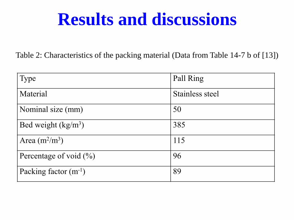
Type Pall Ring
Material Stainless steel
Nominal size (mm) 50
Bed weight (kg/m3) 385
Area (m2/m3) 115
Percentage of void (%) 96
Packing factor (m-1) 89
Table 2: Characteristics of the packing material (Data from Table 14-7 b of [13])
Results and discussions
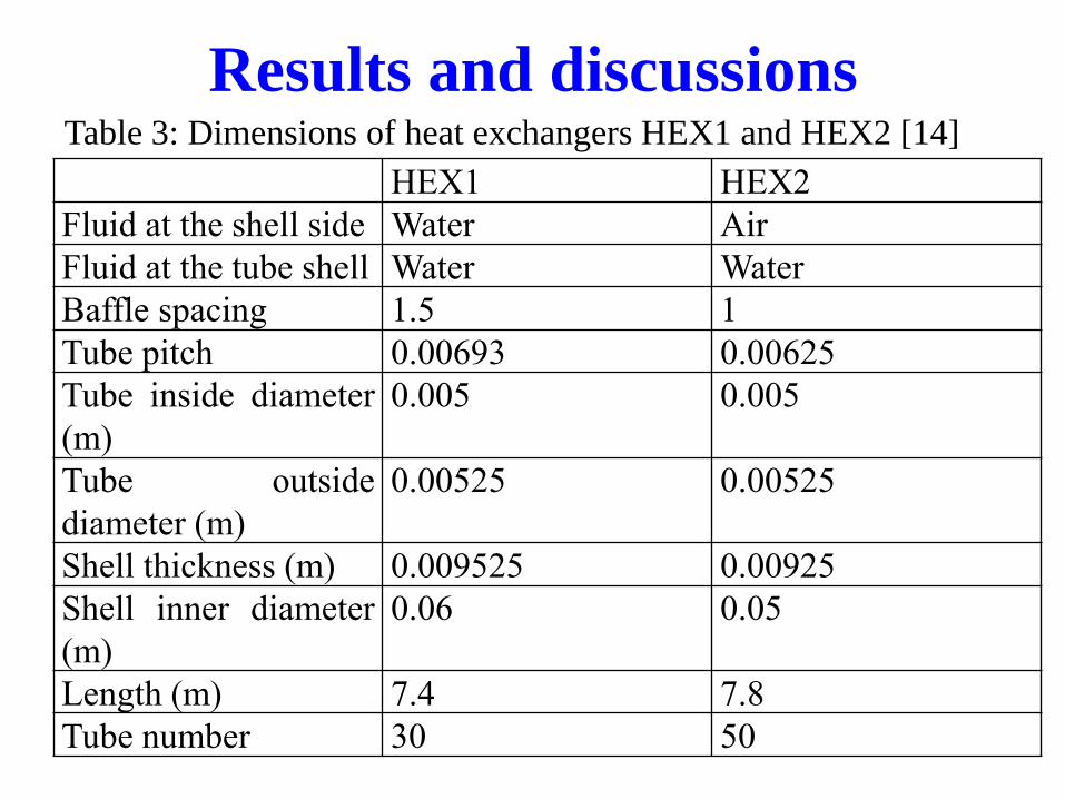
HEX1 HEX2
Fluid at the shell side Water Air
Fluid at the tube shell Water Water
Baffle spacing 1.5 1
Tube pitch 0.00693 0.00625
Tube inside diameter
(m)
0.005 0.005
Tube outside
diameter (m)
0.00525 0.00525
Shell thickness (m) 0.009525 0.00925
Shell inner diameter
(m)
0.06 0.05
Length (m) 7.4 7.8
Tube number 30 50
Table 3: Dimensions of heat exchangers HEX1 and HEX2 [14]
Results and discussions

economizer in
HDAC-SAV
economizer in
HDAC-APC
Fluid at the shell side NH3-poor soln NH3-poor soln
Fluid at the tube side NH3-rich soln NH3-rich soln
Baffle spacing (m) 4 0.25
Tube pitch (m) 0.095 0.045
Tube inside diameter (m) 0.05 0.0254
Tube thickness (m) 0.003 0.002
Shell inner diameter (m) 4.00 0.72
Length (m) 20 15
Tube number 300 30
Tube pass 4 4
Table 4: Dimensions of economizer designed for two systems
Results and discussions

Table 5: Dimensions of generator designed for two systems
generator in
HDAC-SAV
generator in
HDAC-APC
Fluid at the shell side Water flue gas
Fluid at the tube side two phase flow two phase flow
Baffle spacing (m) 25 15
Tube pitch (m) 0.095 0.09
Tube inside diameter (m) 0.05 0.05
Tube thickness (m) 0.003 0.003
Shell inner diameter (m) 0.63 0.36
Length (m) 50 20
Tube number 100 40
Tube pass 1 1
Results and discussions

Results and discussions
absorber in
HDAC-SAV
absorber in
HDAC-APC
Fluid at the shell side Water water
Fluid at the tube side two phase flow two phase flow
Baffle spacing (m) 11.6 3
Tube pitch (m) 0.093 0.09
Tube inside diameter (m) 0.05 0.05
Tube thickness (m) 0.003 0.003
Shell inner diameter (m) 1.41 0.35
Length (m) 35 20
Tube number 500 30
Tube pass 1 1
Table 6: Dimensions of absorber designed for two systems

Results and discussions
Condenser evaporator
Fluid at the shell side Water water
Fluid at the tube side two phase flow two phase flow
Baffle spacing (m) 8 5
Tube pitch (m) 0.049 0.049
Tube inside diameter (m) 0.025 0.025
Tube thickness (m) 0.002 0.002
Shell inner diameter (m) 0.18 0.11
Length (m) 10 4
Tube number 25 10
Tube pass 1 1
Table 7: Dimensions of condenser and evaporator designed for HDAC-APC system

Results and discussions
SAV APC
Fan power(kW) 21.40 21.40
Compression (kW) 8800.64 2.91
Ammonia solution pump(kW) 431.89 4.39
Other pumps (kW) 0.05 0.05
Total(kW) 9200 28.75
Table 8 Power consumption in two systems
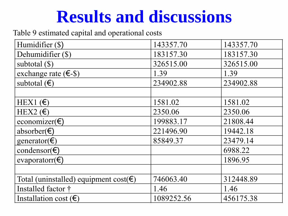
Results and discussions
Humidifier ($) 143357.70 143357.70
Dehumidifier ($) 183157.30 183157.30
subtotal ($) 326515.00 326515.00
exchange rate (€-$) 1.39 1.39
subtotal (€) 234902.88 234902.88
HEX1 (€) 1581.02 1581.02
HEX2 (€) 2350.06 2350.06
economizer(€) 199883.17 21808.44
absorber(€) 221496.90 19442.18
generator(€) 85849.37 23479.14
condensor(€) 6988.22
evaporatorr(€) 1896.95
Total (uninstalled) equipment cost(€) 746063.40 312448.89
Installed factor † 1.46 1.46
Installation cost (€) 1089252.56 456175.38
Table 9 estimated capital and operational costs
Conclusions • This study investigates the feasibility of low grade heat from
process industries as a source for thermal desalination processes via a Humidification Dehumidification process coupled to an absorption chiller (HDAC) with water-ammonia as a working fluid.
• two absorption cooling systems are compared: superheated ammonia vapour (SAV) and ammonia phase change (APC) processes.
• It is found that HDAC+APC process is a better solution with a payback period of less than 10 years and an increased energy saving.
• It is found that HDAC+SAV is not a solution since both capital and operational costs are very high.

Thank you !
Related Documents