CHAPTER 4-1 Cisco VCO/4K Product Overview 78-10999-02 4 Technical Specifications General System Specifications This section lists general technical specifications for all VCO/4K systems. Switch Bus Parameters Measurements of Components Port Capacity 4,096 maximum System Call Capacity Contact the Cisco Systems Technical Assistance Center (TAC) for detailed system capacity information. Voice Encoding Scheme PCM, -law 255, A-Law, to A and A to con version A-law with -law to A-law conversion Combined Controller 15.6 in. (39 cm) high 12.1 in. (30.73 cm) deep 1.58 in. (3.95 cm) wide Power Supply Module 3.0 in. (7.5 cm) high 17.0 in. (42.5 cm) deep 8.0 in. (20 cm) wide VCO/4K System Enclosure 26.13 in. (67.73 cm) high 22.5 in. (58.57 cm) deep 17.5 in. (45.33 cm) wide Footprint — 22.50 x 17.5 in. (57.15 x 45.33 cm)

Welcome message from author
This document is posted to help you gain knowledge. Please leave a comment to let me know what you think about it! Share it to your friends and learn new things together.
Transcript

78-10999-02
C H A P T E R 4
Technical SpecificationsGeneral System SpecificationsThis section lists general technical specifications for all VCO/4K systems.
Switch Bus Parameters
Measurements of Components
Port Capacity 4,096 maximum
System Call Capacity Contact the Cisco Systems Technical Assistance Center (TAC) fordetailed system capacity information.
Voice Encoding Scheme PCM, -law 255, A-Law, to A and A to conversion
A-law with -law to A-law conversion
Combined Controller 15.6 in. (39 cm) high12.1 in. (30.73 cm) deep1.58 in. (3.95 cm) wide
Power Supply Module 3.0 in. (7.5 cm) high17.0 in. (42.5 cm) deep8.0 in. (20 cm) wide
VCO/4K System Enclosure 26.13 in. (67.73 cm) high22.5 in. (58.57 cm) deep17.5 in. (45.33 cm) wideFootprint — 22.50 x 17.5 in. (57.15 x 45.33 cm)
4-1Cisco VCO/4K Product Overview

Chapter 4 Technical SpecificationsGeneral System Specifications
Recommended Clearances
Operating Environment
Subrack 15.75 in. (40.00 cm) high13.25 in. (33.70 cm) deep19.00 in. (48.30 cm) wide
Fan Unit 3.50 in. (8.75 cm) high7.00 in. (17.50 cm) deep17.50 in. (43.75 cm) wide
Front — 36.00 in. (90.00 cm)Rear — 6.00 in. (15.00 cm)Top — 12.00 in. (30.50 cm)Side — 12.00 in. (30.00 cm)
Temperature 40 to 100 F10 to 40 C
Temperature Gradient 15F (10C) per hour
Relative Humidity 20 to 80 percent (%), noncondensing
Altitude 0 to 10,000 ft0 to 3,048 m
4-2Cisco VCO/4K Product Overview
78-10999-02

Chapter 4 Technical SpecificationsGeneral System Specifications
Shipping Environment
Storage Environment
FCC Registration Information
Facility Interface Codes
Temperature –40 to 140F (–40 to 60C)
Temperature Gradient Below condensing
Relative Humidity 5 to 90%, noncondensing
Altitude 0 to 30,000 ft (0 to 9,144 m)
Temperature –4 to 113F (–20 to 45C)
Temperature Gradient Below condensing
Relative Humidity 5 to 90%, noncondensing
Altitude 0 to 10,000 ft (0 to 3,048 m)
Part 68 Registration NumberB4RUSA-23298-PF-E
Ringer Equivalence 018B
E+M TC11M or E Tie trunk, conventional terminal set, 2-wire, Type I, E+M interface,provides battery on M-lead or ground on M-lead
E+M TC31M or E Tie trunk, conventional terminal set, 4-wire, Type I, E+M interface,provides battery on M-lead or ground on M-lead
TC12M or E Tie trunk, conventional terminal set, 2-wire, Type II, E+Minterface, provides battery on M-lead or ground on M-lead
TC32M or E Tie trunk, conventional terminal set, 4-wire, Type II, E+Minterface, provides battery on M-lead or ground on M-lead
4-3Cisco VCO/4K Product Overview
78-10999-02

Chapter 4 Technical SpecificationsCombined Controller Specifications
Combined Controller SpecificationsThis section lists specifications for the Combined Controller.
Central Processing Unit Card
Switch Interface Card
4xT1 N/A (XD Device) 1.544 Mbps D4F framing format
ICC T1 I/O 04DU9-BN/1SN 1.544 Mbps D4F framing format
Microprocessor MC68030 (4 MHz)
Memory 16 MB DRAM
Features Real-time clock with battery backup
VME bus master
SCSI bus interface for storage subsystem access/control
Front Panel Switches RESET — Resets on-board MC68030
ABORT — Interrupts MC68030
Front Panel Indicators RUN LED — Normal operation
FAIL LED — Board failure
STATUS LED — Microprocessor halt condition
SCON LED — CPU is system controller
Power Dissipation 20 watts, typical
Memory 64 KB DRAM
DMA Controller MC68450 (4 MHz)
Power Dissipation 10 watts, typical
4-4Cisco VCO/4K Product Overview
78-10999-02

Chapter 4 Technical SpecificationsSpecifications for Storage/Control I/O Module Assembly
Floppy Disk Drive
Specifications for Storage/Control I/O Module AssemblyThis section lists specifications for the Storage/Control I/O module assembly.
Storage Control I/O Module Interfaces
Formatted Capacity 1.44 megabytes (MB)
Signal Interface SCSI
Recording Method MFM
Media Requirement 3.5-in., high-density micro floppy diskettes
Rotational Speed 300 rpm
Read/Write Heads 2 heads
Track Density 135 tracks per in.
Data Transfer Rate 500 kbps
Power Dissipation 15 watts, typical
Form Factor Half-height
4 EIA/TIA-232 serial ports (master console and remote maintenancemodem)
1 Ethernet transceiver interface
1 Centronics-type parallel interface (system printer)
1 SCSI connector (on CPU-TM front panel–not used)
4-5Cisco VCO/4K Product Overview
78-10999-02

Chapter 4 Technical SpecificationsAlarm Arbiter Card Specifications
Hard Disk Drive
Alarm Arbiter Card Specifications
Formatted Capacity 270 MB/512 bytes per sector
Signal Interface SCSI
Recording Method RLL (2,7)
Spindle Speed 3,600 rpm ( 0.5%)
Read/Write Heads 6 heads
Disks 3 disks
Track Density 824 tracks per in.
I/O Data Transfer Rate 12 Mbps
Auto Head Park Yes
Power Dissipation 20 watts, typical
Form Factor Half-height
Watchdog Timer Parameters After reset– 5 to 7 minutes
Normal operation– 5 to 10 seconds
Alarms:
Types Major, Minor, Aux 1, Aux 2Visual indicators on AAC front panel
External NO and NC relay contacts provided for each alarm
External Contacts Type — 2 Form C
Rating — 0.5A @ 24 VDC, 0.25A @ 120 VAC Resistive load only
Front Panel Switches A-RESET — Resets left system controller (Side A)B-RESET — Resets right system controller (Side B)SELECT A — Side A system controller always activeAUTO — Either system controller can be activeSELECT B — Side B system controller always active
4-6Cisco VCO/4K Product Overview
78-10999-02

Chapter 4 Technical SpecificationsNetwork Bus Controller (NBC3) Specifications
Network Bus Controller (NBC3) Specifications
Front Panel Indicators Active A — Side A is active (LED on)
Active B — Side B is active (LED on)
ALARMS-MAJOR — Major alarm condition
ALARMS-MINOR — Minor alarm condition
ALARMS-AUX1 — Auxiliary alarm 1 condition
ALARMS-AUX2 — Auxiliary alarm 2 condition
Power Dissipation 24 watts, typical
Form Factor Eurocard 2
Microprocessor MC68360 (25 MHz)
Memory 4 MB DRAM
256 Kb EPROM
System Synchronization Clock Input (Ext. or Bus) = 1.544 MHz 75 Hz
External Reference Clock(Bitsclk)
64.0 KHz 3 Hz (Front panel 9-pin male D-sub connector)
Internal Reference Clock 1.544 MHz 50 Hz (complies with Stratum 4 requirements)
Phase Lock Loop
Center Frequency
1.544 MHz
32.768 MHz
4-7Cisco VCO/4K Product Overview
78-10999-02
Chapter 4 Technical SpecificationsDigital Trunk Card Specifications
Digital Trunk Card Specifications
E1-PRI
E1-CAS
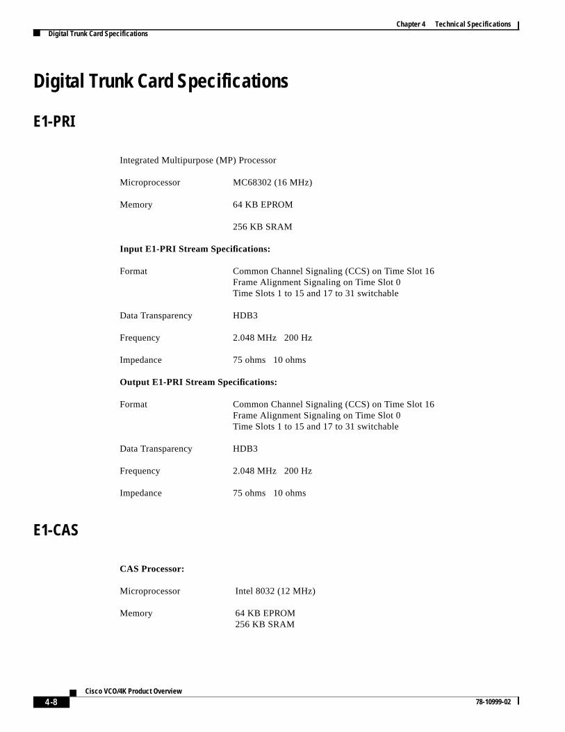
Integrated Multipurpose (MP) Processor
Microprocessor MC68302 (16 MHz)
Memory 64 KB EPROM
256 KB SRAM
Input E1-PRI Stream Specifications:
Format Common Channel Signaling (CCS) on Time Slot 16Frame Alignment Signaling on Time Slot 0Time Slots 1 to 15 and 17 to 31 switchable
Data Transparency HDB3
Frequency 2.048 MHz 200 Hz
Impedance 75 ohms 10 ohms
Output E1-PRI Stream Specifications:
Format Common Channel Signaling (CCS) on Time Slot 16Frame Alignment Signaling on Time Slot 0Time Slots 1 to 15 and 17 to 31 switchable
Data Transparency HDB3
Frequency 2.048 MHz 200 Hz
Impedance 75 ohms 10 ohms
CAS Processor:
Microprocessor Intel 8032 (12 MHz)
Memory 64 KB EPROM256 KB SRAM
4-8Cisco VCO/4K Product Overview
78-10999-02

Chapter 4 Technical SpecificationsDigital Trunk Card Specifications
T1
E1 Stream Specifications:
Format G.703 & G.732 with CRC framing
Ones Density HDB3 coding
Frequency 2.048 MHz+ 200 Hz
Impedance 75 ohms 10 ohms unbalanced120 ohms 10 ohms balanced
Jitter & Wander Complies with CCITT G.823
Applications Interface with D3/D4 digital loop carrier systems, including ChannelSender Units (CSUs), digital channel banks and digital switches
I/O Module 15-pin, D-type, male or RJ-45
Packet Processor:
Microprocessor 8031 (12 MHz)
Memory 8 KB EPROM
2 KB DRAM
Auxiliary Processor:
Microprocessor 8031 (12 MHz)
Memory 8 KB EPROM
Power Dissipation 10 watts, typical
T1 Interfaces Per Card 1
VF Channels Per Card 24 (1 incoming, 1 outgoing stream)
Input Stream Specifications:
Format Bipolar, D3/D4, DS-1
Drive Capability 0 to 655 ft (0 to 200 m) (22 AWG ABAM cable)
Impedance 100 ohms 10 ohms
4-9Cisco VCO/4K Product Overview
78-10999-02

Chapter 4 Technical SpecificationsDigital Trunk Card Specifications
Programmable Four Span T1
Output Stream Specifications:
Format Bipolar, D3/D4, DS-1
Drive Capability 0 to 655 ft (0 to 200 m) (22 AWG ABAM cable)
Impedance 100 ohms 10 ohms
Line Equalization Switch selectable pre-emphasis
Microprocessor (4) MC68302, (1) MC68340
Memory 256K per processor SRAM
64K/68302 EPROM
128K/68340 EPROM
Input T1 Stream:
Format D4 or ESF
Data Encoding Alternate Mark Inversion (AMI)
Data Transparency Selectable bipolar with 8 zero substitution (B8ZS), Bit 7 zerosuppression, or none
Frequency 1.544 MHz 76 Hz
Impedance 100 ohms 10 ohms
Output T1 Stream:
Format D4 or ESF
Data Encoding AMI
Data Transparency B8ZS, Bit 7 zero suppression, or none
Frequency 1.544 MHz 76 Hz
Drive Capability 0 to 655 ft (0 to 200 m) (22AWG ABAM cable)
Impedance 100 ohms 10 ohms
Line Equalization Switch selectable pre-emphasis
4-10Cisco VCO/4K Product Overview
78-10999-02

Chapter 4 Technical SpecificationsDigital Trunk Card Specifications
Programmable Four Span E1
Microprocessor (4) MC68302, (1) MC68340
Memory 256K per processor SRAM
64K/68302 EPROM
128K/68340 EPROM
Input E1 Stream:
Format CAS/MERCAS/R2CRC4CCS/31B
Data Encoding Alternate Mark Inversion (AMI)
Data Transparency HDB3
Frequency 2.048 MHz 100 Hz
Impedance 75 ohms 7.5 ohms or 120 ohms 12 ohms
Output E1 Stream:
Format CAS/MERCAS/R2CRC4CCS/31B
Frequency 2.048 MHz 100 Hz
Impedance 75 ohms 7.5 ohms or 120 ohms 12 ohms
Drive Capability CCITT Recommendation G.703 for75 ohm Coax 120 ohm twisted pair
4-11Cisco VCO/4K Product Overview
78-10999-02

Chapter 4 Technical SpecificationsDigital Trunk Card Specifications
PRI/N Card
Applications Interface with North American -law Primary Rate (23B+D) stream.Supports D-channel protocol handling of the user side and user sidesymmetrical.
Also supports NFAS. Compatible with Northern Telecom DMS-100 andDMS 250, and AT&T 4ESS and 5ESS implementations.
Microprocessor MC68032 (16 MHz)
Memory 32KB EPROM
4 MB DRAM
Input StreamSpecifications:
Format D3/D4 or ESF
Data Transparency B8ZS
Frequency 1.544 MHz+ 200 Hz
Impedance 100 ohms+ 10 ohms
Output StreamSpecifications:
Format D3/D4 or ESF
Data Transparency B8ZS
Drive Capability 0 to 655 ft
Impedance 100 ohms+ 10 ohms
4-12Cisco VCO/4K Product Overview
78-10999-02

Chapter 4 Technical SpecificationsDigital Trunk Card Specifications
ICC with 16 Span T1 I/O Module
ICC With 16-Span E1 I/O Module
Microprocessor Power PC, MPC 860, 50 MHz
Memory 16 MB
8 MB FLASH
Input T1 Stream:
Format D4 or ESF
Data Encoding Alternate Mark Inversion (AMI)
Data Transparency Selectable bipolar with 8 zero substitution(B8ZS), Bit 7 zero stuff, or none
Frequency 1.544 MHz 76 Hz
Impedance 100 ohms 10 ohms
Output T1 Stream:
Drive Capability 0 to 655 ft (0 to 200 m)(22 AWG ABAM cable)
Line Equalization Programmable pre-emphasis
Microprocessor PowerPC, MPC 860, 50 MHz
Memory
16 MB DRAM
8 MB FLASH
Input E1 Stream:
Format CAS/MERCAS/R2CRC4CCS/31BPlus Programmable Protocols
Data Encoding Alternate Mark Inversion (AMI)
4-13Cisco VCO/4K Product Overview
78-10999-02

Chapter 4 Technical SpecificationsDigital Trunk Card Specifications
Drop and Insert Card
Data Transparency HDB3
Frequency 2.048 MHz 100 Hz
Impedance 120 ohms 12 ohms (75 ohms with optional balun)
Microprocessor MC68360
Memory: 1MB DRAM, 72-pin SIMM
256Kb x 8 EPROM
2Kb x 8 EEPROM
Data Ports (Eight identical ports)
Connector: DB-9 female
Signals: XMT Clock and Data, RCV Clk and Data
Levels: EIA/TIA-449/V.35 compatible
Data Options (Selected per port)
Speed: Synchronous 56 Kbps or 64 Kbps
Configuration: DTE or DCE
Bit Ordering: Normal, Reverse modes
Test: Loop Back mode
Operation: Slip and Loss of Clock Detection inDTE mode
4-14Cisco VCO/4K Product Overview
78-10999-02

Chapter 4 Technical SpecificationsService Circuit Card Specifications
Service Circuit Card Specifications
Integrated Prompt and Record Card (IPRC)
Service Platform Card (SPC)
Service Resource Module (SRM)
Microprocessor MC68340 (16 MHz)
SCSI Interface NCR53C94 SCSI Controller
Memory 128 KB EPROM
2-16 MB DRAM
7 KB SRAM
Voice Playback/Record Channels
8 playback/4 record ports64 playback/32 record ports128 playback/32 record ports
Max Prompt Time 35 minutes
Voice Encoding Method 64 Kbps Pulse Code Modulation (PCM)
Microprocessor PowerPC, MPC 860, 50 MHz
Memory 16 MB DRAM
SRM Location 4
Bandwidth 504 per SRM or 2012 per SPC
Microprocessor (8) T1 TMS320C548 (66 MHz)
Memory (8) 96K SRAM
SRM Location 4
Algorithms DTMF Detection, Tone Generation,Conferencing, Call Progress Analysis, MFReception, MFCR2 Processing
4-15Cisco VCO/4K Product Overview
78-10999-02

Chapter 4 Technical SpecificationsPower Supply Module Specifications
fertems
Power Supply Module Specifications
SignalingThe following tables list basic signal and tone information for VCO/4K. For further information, reto the appropriate country tone feature package for your VCO/4K system or contact your Cisco Syssales representative.
Input Voltages –48 VDC, Dual–48 VDC, 120 VAC, or 240 VAC (50/60 Hz)
Output Voltages
+5 VDC
+15 VDC
–15 VDC
+12 VDC
+24 VDC
–48 VDC
Spare Fuse Kit Two replaceable 25-amp fuses for the power supply moduleFour replaceable 30-amp fuses for the power entry module
Power LED Power switch off—LED not illuminatedPower switch on—LED turns green (normal operation)Power switch on—LED turns red (replace power supply module)Power switch on—LED not illuminated (replace a fuse or the powersupply module)
Table 4-1 Tone Plan for North American Digital Tone Generation
Frequencies Level1 Tone
941 Hz + 1336 Hz –7 dBm/freq DTMF 0
697 Hz + 1209 Hz –7 dBm/freq DTMF 1
697 Hz + 1336 Hz –7 dBm/freq DTMF 2
697 Hz + 1447 Hz –7 dBm/freq DTMF 3
770 Hz + 1209 Hz –7 dBm/freq DTMF 4
770 Hz + 1336 Hz –7 dBm/freq DTMF 5
770 Hz + 1447 Hz –7 dBm/freq DTMF 6
852 Hz + 1209 Hz –7 dBm/freq DTMF 7
852 Hz + 1336 Hz –7 dBm/freq DTMF 8
852 Hz + 1447 Hz –7 dBm/freq DTMF 9
4-16Cisco VCO/4K Product Overview
78-10999-02

Chapter 4 Technical SpecificationsPower Supply Module Specifications
697 Hz + 1633 Hz –7 dBm/freq DTMF A
770 Hz + 1633 Hz –7 dBm/freq DTMF B
852 Hz + 1633 Hz –7 dBm/freq DTMF C
941 Hz + 1633 Hz –7 dBm/freq DTMF D
941 Hz + 1209 Hz –7 dBm/freq DTMF *
941 Hz + 1477 Hz –7 dBm/freq DTMF #
1300 Hz + 1500 Hz –7 dBM/freq MF 0
700 Hz + 900 Hz –7 dBM/freq MF 1
700 Hz + 1100 Hz –7 dBM/freq MF 2
900 Hz + 1100 Hz –7 dBM/freq MF 3
700 Hz + 1300 Hz –7 dBM/freq MF 4
900 Hz + 1300 Hz –7 dBM/freq MF 5
1100 Hz + 1300 Hz –7 dBM/freq MF 6
700Hz + 1500 Hz –7 dBM/freq MF 7
900 Hz + 1500 Hz –7 dBM/freq MF 8
1100 Hz + 1500 Hz –7 dBM/freq MF 9
1100 Hz + 1700 Hz –7 dBM/freq MF KP
1500 Hz + 1700 Hz –7 dBM/freq MF ST
700 Hz + 1700 Hz –7 dBM/freq MFSTP3P
900 Hz + 1700 Hz –7 dBM/freq MFSTP
1300 Hz + 1700 Hz –7 dBM/freq MFST2P
– – Quiet
350 Hz + 440 Hz –19 dBm/freq Dial tone
440 Hz + 480 Hz –19 dBm/freq Ringback (steady)
480 Hz + 620 Hz –24 dBm/freq Busy tone
380 Hz –10 dBm Digit trip
440 Hz –13 dBm
480 Hz –17 dBm High tone
920 Hz –13 dBm
1400 Hz –24 dBm
1760 Hz –10 dBm Pay phone trigger tone
1000 Hz 0 dBm CCITT tone
1000 Hz Max output Test tone
404 Hz 0 dBm Test tone
1004 Hz 0 dBm Test tone
2804 Hz 0 dBm Test tone
Table 4-1 Tone Plan for North American Digital Tone Generation (continued)
Frequencies Level1 Tone
4-17Cisco VCO/4K Product Overview
78-10999-02

Chapter 4 Technical SpecificationsPower Supply Module Specifications
440 Hz + 480 Hz –19 dBm/freq Ringback (2 sec ON/4 secOFF)
480 Hz + 620 Hz –24 dBm/freq Busy (.5 sec ON/.5 sec OFF)
480 Hz + 620 Hz –24 dBm/freq Reorder (.25 sec ON/.25 secOFF)
380 Hz NAK (1 sec ON/1 sec OFF)
– –10 dBm/freq
starting level
Cyclic bong tone(repeated every 3.25 sec)
1780 Hz –12 dBm ISUP continuity test tones
2010 Hz –12 dBm ISUP continuity test tones
1. All levels are relative to system 0 TPL.
Table 4-1 Tone Plan for North American Digital Tone Generation (continued)
Frequencies Level1 Tone
4-18Cisco VCO/4K Product Overview
78-10999-02

Chapter 4 Technical SpecificationsPower Supply Module Specifications
Table 4-2 CCITT, Q.441-R2 Signaling Group I Forward Signals
Comb. Desig. Frequencies Meaning1
1. When the signal is the first transmitted on an international link terminating in the destination country of the call.
Meaning2
2. When the signal is other than the first signal on an international link.
1 I-1 1380 + 1500 Hz Language Digit: French Digit 1
2 I-2 1380 + 1620 Hz Language Digit: English Digit 2
3 I-3 1500 + 1620 Hz Language Digit: German Digit 3
4 I-4 1380 + 1740 Hz Language Digit: Russian Digit 4
5 I-5 1500 + 1740 Hz Language Digit: Spanish Digit 5
6 I-6 1620 + 1740 Hz Language Digit: (Spare) Digit 6
7 I-7 1380 + 1860 Hz Language Digit: (Spare) Digit 7
8 I-8 1500 + 1860 Hz Language Digit: (Spare) Digit 8
9 I-9 1620 + 1860 Hz Spare: (Discriminating Digit) Digit 9
10 I-10 1740 + 1860 Hz Discriminating Digit Digit 0
11 I-11 1380 + 1980 Hz Country Code Indicator,outgoing half-echo suppressorrequired
Access to incomingoperator(Code 11).
12 I-12 1500 + 1980 Hz Country Code Indicator, noecho suppressor required
Access to delay operator(Code 12). Request notaccepted.
13 I-13 1620 + 1980 Hz Test Call Indicator (Call byautomatic test equipment)
Access to test equipment(Code 13). Satellite link notincluded.
14 I-14 1749 + 1980 Hz Country Code Indicator,outgoing half-echo suppressorrequired
Incoming half-echosuppressor required.Satellite link included.
15 I-15 1860 + 1980 Hz Not used End-of-pulsing (Code 15).End of identification.
Table 4-3 CCITT, Q.441-R2 Signaling Group II Forward Signals
Comb. Designation Frequencies Meaning Notes
1 II-1 1380 + 1500 Hz Subscriber without priority National Use Only
2 II-2 1380 + 1620 Hz Subscriber with priority
3 II-3 1500 + 1620 Hz Maintenance equipment
4 II-4 1380 + 1740 Hz Spare
5 II-5 1500 + 1740 Hz Operator
6 II-6 1620 + 1740 Hz Data transmission
4-19Cisco VCO/4K Product Overview
78-10999-02

Chapter 4 Technical SpecificationsPower Supply Module Specifications
s
7 II-7 1380 + 1860 Hz Subscriber (or operatorwithout forward transferfacility)
International Use Only
8 II-8 1500 + 1860 Hz Data transmission
9 II-9 1620 + 1860 Hz Subscriber without priority
10 II-10 1740 + 1860 Hz Operator with forwardtransferfacility
11 II-11 1380 + 1980 Hz Spare for National Use
12 II-12 1500 + 1980 Hz
13 II-13 1620 + 1980 Hz
14 II-14 1749 + 1980 Hz
15 II-15 1860 + 1980 Hz
Table 4-4 CCITT, Q.441-R2 Signaling Group A Backward Signals
Comb. Designation Frequencies Meaning
1 A-1 1140 + 1020 Hz Send next digit (n+1)
2 A-2 1140 + 900 Hz Send last but one digit (n-1)
3 A-3 1020 + 900 Hz Address-complete, change over to reception ofGroup B signals
4 A-4 1140 + 780 Hz Congestion in the national network
5 A-5 1020 + 780 Hz Send calling party’s category
6 A-6 900 + 780 Hz Address-complete, charge, set-up speech condition
7 A-7 1140 + 660 Hz Send last but two digit (n-2)
8 A-8 1020 + 660 Hz Send last but three digit (n-3)
9 A-9 900 + 660 Hz Spare (for national use)
10 A-10 780 + 660 Hz Spare (for national use)
11 A-11 1140 + 540 Hz Send country code indicator
12 A-12 1020 + 540 Hz Send language or discriminating digit
13 A-13 900 + 540 Hz Send nature of circuit
14 A-14 780 + 540 Hz Request for information on use of echo suppressor
15 A-15 660 + 540 Hz Congestion in an international exchange or at itsoutput
Table 4-3 CCITT, Q.441-R2 Signaling Group II Forward Signals (continued)
Comb. Designation Frequencies Meaning Notes
4-20Cisco VCO/4K Product Overview
78-10999-02

Chapter 4 Technical SpecificationsPower Supply Module Specifications
Table 4-5 CCITT, Q.441-R2 Signaling Group B Backward Signals
Comb. Designation Frequencies Meaning
1 B-1 1140 + 1020 Hz Spare (for national use)
2 B-2 1140 + 900 Hz Send special information tone
3 B-3 1020 + 900 Hz Subscriber line busy
4 B-4 1140 + 780 Hz Congestion (encountered after change over fromGroup A to Group B signals)
5 B-5 1020 + 780 Hz Unallocated number
6 B-6 900 + 780 Hz Subscriber’s line free, charge
7 B-7 1140 + 660 Hz Subscriber’s line free, no charge
8 B-8 1020 + 660 Hz Subscriber’s line out of order
9 B-9 900 + 600 Hz Spare (for national use)
10 B-10 780 + 660 Hz
11 B-11 1140 + 540 Hz
12 B-12 1020 + 540 Hz
13 B-13 900 + 540 Hz
14 B-14 780 + 540 Hz
15 B-15 660 + 540 Hz
4-21Cisco VCO/4K Product Overview
78-10999-02

Chapter 4 Technical SpecificationsPower Supply Module Specifications
4-22Cisco VCO/4K Product Overview
78-10999-02
Related Documents