TECHNICAL REPORTS SERIES No. 224 Interaction of Grid Characteristics with Design and Performance of Nuclear Power Plants A Guidebook INTERNATIONAL ATOMIC ENERGY AGENCY, VIENNA, 1983

Welcome message from author
This document is posted to help you gain knowledge. Please leave a comment to let me know what you think about it! Share it to your friends and learn new things together.
Transcript

TECHNICAL REPORTS SERIES No. 224
Interactionof Grid Characteristics
with Design and Performanceof Nuclear Power Plants
A Guidebook
INTERNATIONAL ATOMIC ENERGY AGENCY, VIENNA, 1983

Interaction of grid characteristicAN: 076951 C.2UN: 621.311.2:621.039 1614
000004541=05

0 / 6 9 5 1
INTERACTIONOF GRID CHARACTERISTICS
WITH DESIGN AND PERFORMANCEOF NUCLEAR POWER PLANTS
A Guidebook

The following States are Members of the International Atomic Energy Agency:
AFGHANISTANALBANIAALGERIAARGENTINAAUSTRALIAAUSTRIABANGLADESHBELGIUMBOLIVIABRAZILBULGARIABURMABYELORUSSIAN SOVIET
SOCIALIST REPUBLICCANADACHILECOLOMBIACOSTA RICACUBACYPRUSCZECHOSLOVAKIADEMOCRATIC KAMPUCHEADEMOCRATIC PEOPLE'S
REPUBLIC OF KOREADENMARKDOMINICAN REPUBLICECUADOREGYPTEL SALVADORETHIOPIAFINLANDFRANCEGABONGERMAN DEMOCRATIC REPUBLICGERMANY, FEDERAL REPUBLIC OFGHANAGREECEGUATEMALAHAITI
HOLY SEEHUNGARYICELANDINDIAINDONESIAIRAN, ISLAMIC REPUBLIC OFIRAQIRELANDISRAELITALYIVORY COASTJAMAICAJAPANJORDANKENYAKOREA, REPUBLIC OFKUWAITLEBANONLIBERIA
-LIBYAN ARAB JAMAHIRIYALIECHTENSTEINLUXEMBOURGMADAGASCARMALAYSIAMALIMAURITIUSMEXICOMONACOMONGOLIAMOROCCONETHERLANDSNEW ZEALANDNICARAGUANIGERNIGERIANORWAYPAKISTANPANAMAPARAGUAYPERU
PHILIPPINESPOLANDPORTUGALQATARROMANIASAUDI ARABIASENEGALSIERRA LEONESINGAPORESOUTH AFRICASPAINSRI LANKASUDANSWEDENSWITZERLANDSYRIAN ARAB REPUBLICTHAILANDTUNISIATURKEYUGANDAUKRAINIAN SOVIET SOCIALIST
REPUBLICUNION OF SOVIET SOCIALIST
REPUBLICSUNITED ARAB EMIRATESUNITED KINGDOM OF GREAT
BRITAIN AND NORTHERNIRELAND
UNITED REPUBLIC OFCAMEROON
UNITED REPUBLIC OFTANZANIA
UNITED STATES OF AMERICAURUGUAYVENEZUELAVIET NAMYUGOSLAVIAZAIREZAMBIA
The Agency's Statute was approved on 23 October 1956 by the Conference on the Statute of theIAEA held at United Nations Headquarters, New York; it entered into .force on 29 July 1957. TheHeadquarters of the Agency are situated in Vienna. Its principal objective is "to accelerate and enlarge thecontribution of atomic energy to peace, health and prosperity throughout the world".
© IAEA, 1983
Permission to reproduce or translate the information contained in this publication may be obtainedby writing to the International Atomic Energy Agency, Wagramerstrasse 5, P.O. Box 100, A-1400 Vienna,Austria.
Printed by the IAEA in AustriaJanuary 1983

TECHNICAL REPORTS SERIES No. 224
INTERACTIONOF GRID CHARACTERISTICS
WITH DESIGN AND PERFORMANCEOF NUCLEAR POWER PLANTS
A Guidebook
INTERNATIONAL ATOMIC ENERGY AGENCYVIENNA, 1983

INTERACTION OF GRID CHARACTERISTICS WITH DESIGN ANDPERFORMANCE OF NUCLEAR POWER PLANTS: A GUIDEBOOK
IAEA, VIENNA, 1983STI/DOC/10/224
ISBN 92-0-155183-5

FOREWORD
Safe and economic operation of nuclear power plants requires an off-siteelectric power supply system with a capacity adequate to provide the necessarysupport for safe start-up, running and shut-down of the plant, a grid capable ofdispatching the load and having stable characteristics, and a protection systemwhich keeps disturbances at a low level and of short duration and which preventsdisturbance propagation through the system. Such requirements involve con-siderable expenditure on the acquisition of adequate equipment and the pro-vision of supporting capacity and may be beyond the investment capabilities ofthe electric utilities of some developing countries. In such countries, thesystem capacity typically lags behind the demand; the grid characteristicsgive rise to fluctuations because of inadequacies in the control equipment;and the protection system has poor co-ordination and/or reliability, withexcessive fault clearing time. These features are clearly unsuitable for safeand economic operation of nuclear power plants and could represent a severeconstraint on the use of nuclear power for electricity generation in developingcountries.
The purpose of this Guidebook is to advise engineers, designers andoperators of electric power systems in developing countries on the type ofproblem they may encounter when expanding their power systems by theaddition of a nuclear power plant.
The text of the Guidebook is divided into six sections: Section 1 presentsan introductory overview, detailing the objectives of the Guidebook and givinggeneral concepts and definitions. Section 2 contains a summary and con-clusions. Section 3 describes the relevant design characteristics of provennuclear power plants which are currently available for export. Section 4 dis-cusses the interdependence of grid and nuclear power plant and suggestsmeasures for mitigating possible operational problems. Section 5 describesthose actions which should be considered by the owner of a nuclear powerplant before its introduction into the power system. These actions identifythe operating characteristics of the electric power system and provide the basisfor preliminary discussions with potential suppliers. Finally, the Appendixreports some relevant examples of operating experience.
This Guidebook has been prepared within the framework of a series oftechnical documents compiled by the IAEA's Division of Nuclear Power. Someof these have already been published, for instance: Manpower Developmentfor Nuclear Power: A Guidebook (IAEA Technical Reports Series No. 200,

1980), Economic Evaluation of Bids for Nuclear Power Plants (IAEA TechnicalReports Series No. 175, 1967), Technical Evaluation of Bids for Nuclear PowerPlants: A Guidebook (IAEA Technical Reports Series No. 204, 1981), andGuidebook on the Introduction of Nuclear Power (IAEA Technical ReportsSeries No. 217, 1982). Supplementary guidebooks are under preparation; theytreat subjects such as: Control and Instrumentation of Nuclear Power Plants,Nuclear Power Project Management, and Bid Specifications.
Appreciation is expressed of the valuable contributions of W. Aleite(Kraftwerk Union, Federal Republic of Germany), G. Ghosh (Rajasthan AtomicPower Station, India) and M. Nelken (Israel Electric Corporation Ltd., Israel).Thanks are also due to D.J. Love (Bechtel Espafia, Spain), R.N. Carson andF.Y. Tajaddodi (Bechtel Power Corp., Los Angeles, United States of America),R.N. Ray (Bhabha Atomic Research Centre, India), W. Bayer (Siemens AG,Federal Republic of Germany), H. Kurten (Kraftwerk Union, Federal Republicof Germany) and R. Weaner (Department of Energy, United States of America)for a review of the text and for constructive comments.

CONTENTS
1. INTRODUCTION 1
1.1. Definition of grid characteristics 21.1.1. Grid reliability 31.1.2. Grid quality 41.1.3. Grid protection 4
1.2. Electric power system characteristics 4
2. SUMMARY AND CONCLUSIONS 7
2.1. Size selection of nuclear power plants 92.2. Meeting the system load-change requirements 102.3. Integration of nuclear power plants into the power system 122.4. Conclusions 17
3. CHARACTERISTIC FEATURES OF NUCLEAR POWER PLANTS .. 18
3.1. Types of nuclear power plants 183.1.1. Reactors with off-load refuelling system 183.1.2. Reactors with on-load refuelling system 19
3.2. Operational modes of nuclear power plants 203.2.1. Constant-load plants 213.2.2. Scheduled and arbitrary load-follow plants 21
3.3. Quality of electric power supply 223.3.1. External grid power supply 223.3.2. Power supplies for station services 223.3.3. Voltage and frequency deviation of the external grid 25
3.3.3.1. Changes in voltage 253.3.3.2. Changes in frequency 26
3.4. Operational characteristics of nuclear power plants 273.4.1. Start-up from cold reactor and cold turbine
to nominal power operation 283.4.2. Start-up from hot reactor and hot turbine to nominal
power operation 283.4.3. Reactor power set-back capabilities 29
3.4.3.1. External reasons for NPP set-back operation 293.4.3.2. Internal reasons for NPP set-back operation 303.4.3.3. Minimum load with automatic control (MILAC)
and minimum load for quick return (MILQUICK) .. 30

3.5. Limitations of load-change capabilities of nuclear power plants 313.5.1. Restrictions in output changes due to fuel performance 323.5.2. Restrictions in output changes due to reactivity limitations ... 333.5.3. Restrictions in output changes due to thermal stresses
in materials 33
4. INTERACTION OF GRID AND NUCLEAR POWER PLANT 36
4.1. Influence of the grid on the nuclear power plant 364.1.1. Effects of frequency change on NPP operation 37
4.1.1.1. Sharp drop in frequency 374.1.1.2. Sharp rise in frequency 384.1.1.3. Prolonged off-nominal frequency conditions 38
4.1.2. Effects of voltage change on NPP operation 394.1.2.1. Sharp drop in voltage 394.1.2.2. Sharp rise in voltage 404.1.2.3. Prolonged off-nominal voltage operation 40
4.2. Influence of the nuclear power plant on the grid 414.3. Improving the nuclear power plant/grid interface 41
4.3.1. Nuclear power plant design 414.3.2. Grid characteristics 43
5. ANALYSIS OF THE POWER SYSTEM CHARACTERISTICS 47
5.1. Data base of the existing system 475.1.1. Non-monitored data 485.1.2. Data from continuous monitoring 48
5.1.2.1. Normal operating conditions 495.1.2.2. Disturbances not involving loss of
generating capacity 495.1.2.3. Disturbances involving loss of generating
capacity 505.1.3. Data from special monitoring 50
5.1.3.1. High-speed frequency recording during normaloperating conditions 51
5.1.3.2. High-speed frequency recording duringdisturbances 51
5.1.3.3. High-speed voltage recording during disturbances .. 515.2. Improvement of system monitoring 51
5.2.1. Additional data on the existing supply system 525.2.2. Data processing and storage 52

5.3.- Evolution of grid characteristics 525.3.1. Updating of grid information 54
5.4. Modelling of nuclear power plant integration into the grid 54
APPENDIX: CASE STUDIES 57
A-l. Low-performance grid incorporating a nuclear power plant 57A-2. Small grid incorporating a generating unit with relatively
high nominal rating 65
LIST OF PARTICIPANTS 67

1. INTRODUCTION
Faced with the need' of achieving the highest possible efficiency in theutilization of primary resources, power system managers should consider nuclearpower plants (NPPs) as a viable alternative or addition to their present fossil fuelor hydroelectric plants.
Problems of operating a NPP within an electric grid of limited capacity havelong been a serious concern to electric utilities because of the grid's directbearing on the starting and running of the NPP.
Some of these problems fall within conventional electric system manage-ment and are therefore not a subject of this Guidebook. Some of these problems,however, will be mentioned wherever they have a direct bearing on NPP opera-tion. While, in fact, essentially focused on nuclear aspects, this Guidebook cannottotally ignore problems the solution of which, although conventional, could easeand accelerate the introduction of nuclear energy in a developing country. There-fore, load studies, load management, short-circuit studies, voltage and frequencystudies are discussed only to the extent that the demands for NPPs may be morerestrictive than those for fossil plants. Large power systems have successfullyaccepted NPPs within their electric grids, but smaller power systems, whichtypically exist in developing countries, will face problems unique to NPPsbecause these have special features and important safety systems which arenecessary for safe reactor shut-down and require a high level of off-site powersupport.
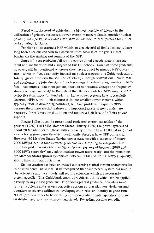
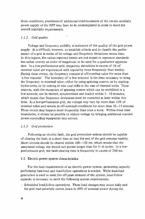
Figure 1 illustrates the present and projected system capacities of thepresent (1980) 110 IAEA Member States. During 1980, the power systems ofabout 20 Member States (those with a capacity of more than 12 000 MW(e)) hadan electric system capacity which could easily absorb a large NPP on its grid.However, 60 Member States (having power systems with a capacity of below2000 MW(e)) would face extreme problems in attempting to integrate a NPPinto their grid. Twenty Member States (power systems of between 2000 and6000 MW(e) capacity) may adapt nuclear power more easily, and the remainingten Member States (power systems of between 6000 and 12 000 MW(e) capacity)should have minimal difficulties.
Strong caution has been expressed concerning typical system characteristicsto be considered, since it must be recognized that each power system has uniquecharacteristics and most likely will require solutions which are necessarilysystem specific. This Guidebook cannot provide solutions which can be applieddirectly to single-case problems. It provides general guidance, describes sometypical problems and suggests corrective actions so that planners, designers andoperators of electric utilities in developing countries can identify in good timecritical problem areas to be carefully considered when tender specifications areestablished and supply contracts negotiated. Regarding possible remedial
110
1980 1985 1995 20001990
YEAR
FIG.]. Distribution of national electric system capacities in IAEA Member States.
actions suggested in this Guidebook, its users should bear in mind that theviability of the proposed solutions for their specific situation should be verified,balancing the possible improvements against the financial commitments theymay involve. In this respect, throughout the Guidebook the term recommenda-tion is intentionally avoided, since the users should not be directed to anysolution without having first evaluated its viability through a cost/benefitassessment.
1.1. Definition of grid characteristics
For the purposes of this Guidebook, it is convenient to recognize that inlarge interconnected systems the electric grid is generally stable and has adequatecapacity to provide the necessary power to assure safe start-up, operation andshut-down of a NPP. However, this Guidebook is directed towards those power

systems which do not have such capacity, but which have the capability to beexpanded and which have characteristics suitable for NPPs. In order to dif-ferentiate between such systems, mention is made in the text of high-performanceand low-performance systems.
A high-performance system capable of performing the necessary responsesto load and generation trends and perturbations will normally have the followingcharacteristics:
— Adequate grid interconnection, involving multiple parallel lines— Adequate reserve margins, especially spinning reserves— Modern load dispatching centres in operation— A reliable high-speed protective system continually in operation.
With the above capabilities, the grid— maintains narrow limits of frequency and voltage fluctuations— does not permit prolonged off-nominal frequency and voltage operation— keeps disturbances and transients to short duration, and prevents their
propagation throughout the system.
A low-performance system would have much lower capabilities, such as:
— Inadequate number of tie lines in the grid— Inadequacy of system reserve, particularly spinning reserve— Inadequacy of protective relays capable of fast fault identification— Improper relay co-ordination— Absence of fast-acting circuit breakers for quick fault clearance— Inadequate voltage control equipment— Inadequate generation control and load-shedding schemes for system
frequency regulation or total absence of them.
With the above limited capabilities the grid— may experience voltage and frequency fluctuations of high magnitude— has long periods at off-nominal frequency and voltage conditions— has frequent and/or extended unscheduled generation and/or transmission
outages.
1.1.1. Grid reliability
The degree to which the grid can maintain an uninterruptible power supplyis the measure of grid reliability.
While total grid power failure is a rather unlikely event even in a low-performance grid, power failure in important nodes of the high-voltage grid,particularly at the points where the NPP will be connected to the grid, may beexperienced more frequently than once a year in a low-performance grid. Under
these conditions, provisions of additional reinforcements of the on-site auxiliarypower supply of the NPP may have to be contemplated in order to meet theoverall reliability requirements.
1.1.2. Grid quality
Voltage and frequency stability is indicative of the quality of the grid powersupply. It is difficult, however, to establish criteria and to classify the perfor-mance of a grid in terms of its voltage and frequency deviations versus time.In this respect, the values reported herein are not meant to represent standardsbut rather convey an order of magnitude to be used for a qualitative apprecia-tion. In a low-performance grid, frequency deviations in excess of 1% ofnominal value are experienced with regularity more frequently than weekly.During these events, the frequency remains at off-nominal value for more than'a few minutes'. The boundary of 'a few minutes' is the time necessary to bringthe frequency to nominal value, either by using spinning reserve, or by startinghydro-units, or by cutting in new coal mills in the case of thermal units. Thesereserves, with the exception of spinning reserve which can be mobilized in afew seconds, can be started, synchronized and loaded within 5 — 10 minutes,which means that frequency deviations must be corrected at least within thistime. In a low-performance grid, the voltage may vary by more than 10% ofnominal value and remain at off-nominal conditions for more than 10—15 minutes.These events may happen more frequently than once a week. Within these timeboundaries, it should be possible to restore voltage by bringing additional reactivepower-controlling' equipment into service.
1.1.3. Grid protection
Following an electric fault, the grid protection system should be capableof clearing the fault in a short time so that the rest of the grid remains healthy.Short circuits should be cleared within 100-150 ms, which means that theassociated voltage dip should not persist longer than for 5-8 cycles. In a low-performance grid, the fault-clearing time is frequently in excess of 200 ms.
1.2. Electric power system characteristics
For the load requirements of an electric power system, generating capacityperforming base-load and load-follow operations is needed. While base-loadgeneration is used to meet the off-peak demand of the system, load-followcapacity is necessary to meet the following system requirements:
- Scheduled load-follow operations. These load changes may occur daily andthe grid load generally comes down to 50% of nominal power during the

low-demand period. Power change rates generally remain between 0.1 and 1%of nominal power per minute.
- System regulation. This is required to compensate for the dynamic loadchanges and generally occurs with a frequency of several times per day;normally, it remains within a magnitude range of 3—5% of the plant'snominal power and within a rate-of-power change of 1% of nominal powerper minute. These load changes are usually prompted by the load dispatchoptimization strategy.
— Network frequency control. This is required to compensate for the randomload changes of small magnitude; typically, it remains within a few per centof the plant's rated output (frequency control band) and is taken care of bythe turbine frequency control system.
— Contingency operations. These load changes are usually prompted by gridsystem upset or fault conditions and require provisions for adequate spinningreserve in the supply system. Spinning reserve is the amount of load pick-upa unit can supply immediately when operating at reduced power level. Thespinning reserve assigned to any given plant depends on the mixture and sizeof the units on the grid.
A high-performance electric power system would have enough generatingcapacity to meet the demand, a grid capable of efficiently dispatching the powergenerated at any time, and adequate capability to keep transient conditions atsuch a level and duration that equipment is not damaged and users are notdisturbed.
Transients are caused by electric faults and by the impossibility of thesupply system to follow the actual load demand on the grid. These transientconditions determine grid frequency and voltage fluctuations.
- Supply/demand mismatch leads to an imbalance of active and reactive powerin the system, and to grid frequency and voltage deviations from nominalvalues. Under these conditions, each generating unit of the system must beprompted by a loading signal into generating its own share of active and/orreactive power in order to re-establish nominal load conditions in the system.
— Electric faults and consequent short circuits cause a voltage dip and an over-current whose magnitude and duration depend upon the type of fault and theability of the protection system to clear the fault within a short time.
These events will basically determine the following situations.
(a) Imbalance of active power generates off-nominal frequency conditions.- The speed of the turbine deviates from its rated value and may approach
resonant speed values at which high vibrations may induce blade failuresin the low-pressure turbine buckets. Turbine operation at off-nominalfrequency is rigorously restricted (see Section 4.1.1.3).
0.8
0.6
0.4
overexcited
0.2
0.2
underexcited
0.4
0.6
0.8
Limiting by permissible temperature• rise in exciter winding
^Limiting by permissibletemperature rise in
* stator winding
0.2 0.4
'N\
Limiting by permissibletemperature rise in endsof stator laminations
Practical limiting bystatic stability
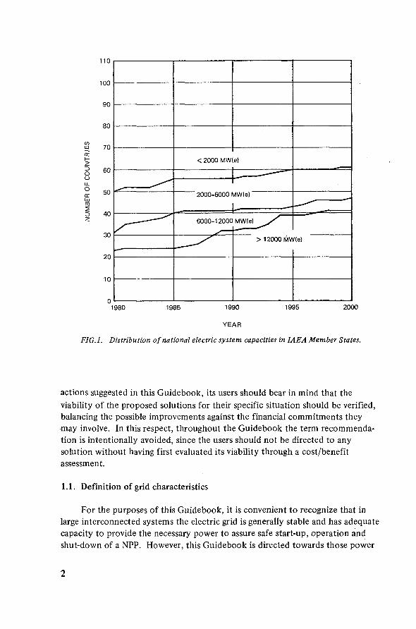
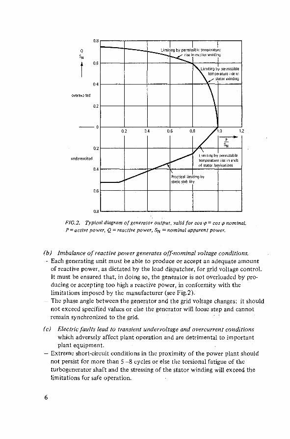
FIG.2. Typical diagram of generator output, valid for cos <p= cosy nominal.P = active power, Q = reactive power, 5>j = nominal apparent power.
(b) Imbalance of reactive power generates off-nominal voltage conditions.- Each generating unit must be able to produce or accept an adequate amount
of reactive power, as dictated by the load dispatcher, for grid voltage control.It must be ensured that, in doing so, the generator is not overloaded by pro-ducing or accepting too high a reactive power, in conformity with thelimitations imposed by the manufacturer (see Fig.2).
- The phase angle between the generator and the grid voltage changes; it shouldnot exceed specified values or else the generator will loose step and cannotremain synchronized to the grid.
(c) Electric faults lead to transient undervoltage and overcurrent conditionswhich adversely affect plant operation and are detrimental to importantplant equipment.
- Extreme short-circuit conditions in the proximity of the power plant shouldnot persist for more than 5-8 cycles or else the torsional fatigue of theturbogenerator shaft and the stressing of the stator winding will exceed thelimitations for safe operation.

From the above, it follows that voltage and frequency deviations fromnominal values are recurring events in electric grids. Their magnitude andfrequency of occurrence will depend, however, upon the causative situationand the characteristics of the power system, and may vary from narrow bandfluctuations and transient conditions of short duration in a high-performancesystem to large variations and prolonged off-nominal conditions in a low-performance system. In conclusion, the ability of an electric power system tosafely absorb the integration of a NPP into its grid will depend on its capabilityof maintaining an uninterrupted supply while keeping frequency and voltagedeviations within small bands and of short duration. These conditions are met if:
— the expansion of the generating capacity of the system is properly plannedand implemented in good time, and adequate reserve is provided in thesystem, especially spinning reserve
— the transmission system is continually reinforced to provide reliable routesfor power dispatch and distribution
— efficient generation control is realized by a strategy of economic dispatchoptimization
— the voltage profile at critical points of the system is ensured by adequatereactive power control equipment
— a high-speed, reliable and well co-ordinated protection system is continuallyin operation
— efficient automatic load shedding and load restoration schemes exist.
The above-mentioned requirements are capital-intensive and representsignificant additions to the already high investments associated with a NPP.Consequently, the introduction of a NPP into a low-performance system willinvolve unprecedented requirements in system upgrading whose economicimplications must be carefully accounted for in a cost/benefit assessment whenperforming a nuclear power feasibility study.
2. SUMMARY AND CONCLUSIONS
When considering the expansion of the electric power system by the addi-tion of a new unit, the utility must find answers to the following questions:
- What is the most economic size of the additional unit?- Is the operating performance of the envisaged unit adequate to meet the load
requirements of the system?- What can be done to mitigate the problems associated with the mutually
induced plant/grid dynamic interaction?

These problems will be even more important if the system has limitedcapabilities and if its expansion is to be made by a first NPP, which will generallybe the largest unit operating in the system and probably represent the largestinvestment the utility has ever made in a power project. These problems willtypically be faced by electric utilities in developing countries at the outset of anuclear power programme.
Before addressing the above questions, it is convenient to recognize thatNPPs have special characteristics whose implications must be carefully con-sidered at a very early stage as they may affect the electric grid and may them-selves be affected by it. Relevant considerations include the following points:
- Unlike fossil-fuelled power stations, NPPs cannot be easily tailored to therequirements of operators. Nuclear steam supply systems (NSSS) generallyexist as proven, licensable designs of large size. These large sizes introduceeconomic penalties regarding the provision of additional reserves in a low-performance system for frequency control and quick system recovery afteran abnormal occurrence. The investments associated with such provisionsmust be assessed on a cost/benefit basis against the economy of scale forunits of large size.
- To supply and distribute essential power to the NPP safety systems duringnormal operational states, and during and after accident conditions, theon-site power supply and its emergency system must be engineered so as tohave a reliability consistent with all the requirements of the safety systemsto be supplied. Removal of residual heat for safe plant shut-down requiresan uninterruptible and stabilized auxiliary power supply which must beavailable at any time during the NPP lifetime; this is a requirement of safetysignificance. In a low-performance system where the reliability of the gridpower supply may be low, the on-site power supply reliability shall be suchthat a high overall reliability is achieved. This condition may call foradditional provisions and for redundancy.
- Mainly designed for operation in high-performance grids, NPPs do not tolerateprolonged operation at off-nominal voltage and frequency conditions. Theseoccurrences are not uncommon in low-performance grids. Therefore, appro-priate and sometimes extensive grid system improvements and reinforcementsmay become necessary.
- Because of the large size of components, the special construction requirements,the impact of radiation and the more stringent safety requirements of nuclearpower plants, the material stresses under thermal cycling conditions are morecritical for NPPs than for conventional fossil-fuelled units. The number ofpower cycles and their intensity and gradient must not exceed the permissiblelimits since this may result in shortening of the plant lifetime. Hence limita-tions are imposed on the power-change capability of NPPs and the permissiblechanges must be verified against the expected load-change requirements of the
8

grid. These limits require that NPP operating procedures be strictly adhered toby the operator.
- System load requirements may necessitate special operational features (i.e. load-follow capability) to be introduced in NPP design. The economic significanceof such design characteristics must be carefully considered at a very early stage.Preliminary discussions with potential suppliers are an absolute necessity.
— Inspections, repair and maintenance, and off-load refuelling (for LWRs)require provisions of adequate reserves in the supply system as well as capablemanagement to devise appropriate load strategies of the other generating unitsin order to ensure system stability during prolonged NPP down-times.
2.1. Size selection of nuclear power plants
The high safety standards to which NPPs are licensed for operation requirecomplex engineered safety systems and reliable auxiliary systems which areunprecedented in units of conventional types. The investments associated withthese systems penalize the capital costs of NPPs as compared with fossil-fuelledplants of the same capacity. The economy of scale has consequently a majorimpact on NPPs and this is the reason why NPPs have developed in a range ofrapidly increasing unit size. At present, commercially available designs of NSSSmay still be too large for the electric grid of many developing countries (seeFig. 1) which may not be able to ensure system stability when the NPP is notavailable. At present, a number of manufacturers supply commercially availableNSSS.1 They would normally supply equipment in the large size range. Inprinciple, a manufacturer may be willing to bid for units in a small size range,but such plants should be regarded as the first ones of a kind for which econo-mics, licensability and reliability may still be open issues. At present, the onlyproven NPP types commercially available for export include PHWRs, PWRs andBWRs. The minimum size range at which these NSSS are manufactured and whichmay be termed as proven is 450-600 MW(e).
Nuclear power plants have the lowest marginal fuel cost of all types ofpower stations other than run-of-river hydro power plants and their continuousoperation at nominal power is therefore the utility's first choice for economicelectricity generation. However, the size of the power system in some developingcountries may be so limited that its off-peak load demand is too low to permitconstant load operation of the NPP. In this case, the need of providing someload-follow capability will of necessity add to the plant cost because ofadditional design and engineering complexity as well as the required instrumenta-tion and degree of automation in the plant control system.
1 This is extensively discussed in the Guidebook on the Introduction of Nuclear Power(Technical Reports Series No.217, IAEA, 1982) to which reference is made for completeinformation.

In conclusion, the size selection should be a factor in all implicationsassociated with making NPP operation viable in a low-performance system.Therefore, the following points should be carefully considered:
- Cost of extensive NPP engineering, such as load-follow capabilities, additionalequipment, adequate instrumentation and control system, and effectiveprotection system to withstand transient conditions from the grid, to ensureadequate performance and to guarantee the designed plant life.
- Cost of meeting the increased reliability requirements for the on-site emer-gency power supply to ensure the performance of the essential safety functionsof the NPP.
- Cost of maintaining grid stability when the NPP is not available. This iscomprised of costs for providing additional spinning reserve, establishingeffective system generation control, enhancing the performance of the gridprotection system, and reinforcing the transmission system.
2.2. Meeting the system load-change requirements
Nuclear power plants are more sensitive to stresses induced by thermalcycling associated with load-follow operation than conventional plants becauseof their characteristic larger sizes, thicker walls and massiveness of components.Critical points particularly sensitive to these stresses include component walls,nozzles and adjacent areas, tanks of small mass-to-flow ratio, points subject tolarge temperature changes, etc.
Also improper changes in the fuel power density distribution associatedwith load-change operation may induce incorrect pellet/clad interaction andlead to some fuel failures. While generation at constant nominal load will pro-vide the most economical operation of NPPs, it must be recognized that whenold conventional units with good load regulation performance are scrapped andthe share of the nuclear installed capacity is increased by additional NPPs comingon line, the evolving power system characteristics will require that NPPs alsoprovide load-follow service.
When judging the capability of a NPP to respond to the system load require-ments, the utility should first perform power system studies and load demandprojections to ascertain what operational mode will be reserved to the envisagedNPP. In this respect, the utility must evaluate the typical daily load curve of thesystem at the time of future NPP commissioning. The expected load-followcapability of the NPP can then be derived with the known peak and off-peakload demand, the rate of load-change requirements of the system and the opti-mal loading order established for all generating units of the system. In essence,these studies will reveal the loading/unloading pattern which may be reserved tothe NPP. A careful NPP design review must verify that the thermal stressesinduced by the power changes associated with the expected loading/unloading
10
pattern for the NPP remain within the limitations imposed by the equipmentmanufacturers both in the NSSS and the BOP.
This analysis is difficult because it requires not only a good knowledge ofthe present supply system but also an accurate projection of its configurationat the time of NPP commissioning. Considering that the selection of theappropriate design characteristics is a decision to be made at an early stage andthat building a NPP may take ten years, the utility must carefully project theexpansion of its system over a time span of more than ten years. In particular,the mixture of the other generating units and their combined load regulationcapability at the time of NPP commissioning will be essential in establishingwhat total load-follow capacity will be available to meet the load-change require-ments of the system and in selecting the most favourable loading strategy forthe NPP.
In selecting the NPP design, the utility must exercise the utmost care inverifying whether the operating performance of the NPP will meet the func-tional requirements of the power system. This means that the number and typeof power changes which the equipment manufacturer guarantees for safe opera-tion should not be exceeded by the operator when running the NPP or else theoperating life of the components will be reduced. In essence, if the NPP is notcapable to meet all the load-change rates and magnitudes required by the system,the additional requirements will have to be met by the load-follow generatingcapacity of the conventional units of the supply system; otherwise, additionalcycling capacity will have to be installed and the resulting economic penaltymust be carefully considered by the planners in their system expansion evalua-tion. Section 3.5 will provide more information and assist in clarifying thecorrect approach to these problems.
In reviewing the NPP ability to respond to the functional requirements ofthe power system, the following points must be considered.
A low-performance power system will typically experience a higher numberof critical occurrences than a high-performance system. This will result in alarger number of events inducing off-nominal frequency and voltage conditionsat which the NPP may not be able to operate. The system operator must there-fore devise a way of protecting the NPP from those transient conditions whichcannot be normally withstood. However, the protection should not systemati-cally imply an interruption of generation since this would adversely affect theavailability of the NPP in a low-performance system. A plant trip including thereactor should be regarded as a last resort to prevent occurrences which may havesafety-relevant effects. During a trip the plant is subject to a high rate of powerchange, which consumes a part of its operational life. Considering that tripsfor plant refuelling (in LWRs) and maintenance are 'incompressible' operationalrequirements, utmost care should be exercised to warrant that the plant istripped only when needed, thus preventing any unnecessary reduction of plant
11
life. An appropriate system islanding scheme should be engineered which, aftera serious grid-induced occurrence, will allow the NPP to remain synchronized tothe islanded system without interrupting generation. This system sectioninginto subsystems may reduce the load to be served by the NPP; therefore, itsgeneration may have to be reduced accordingly. This requires that in systemupset conditions the NPP should be able to perform a quick set-back to pre-determined intermediate power levels which must be compatible with the loadthe NPP will then be serving in the isolated system.
Under particularly severe conditions, it may even be necessary to islandthe NPP on itself so that it only serves its own auxiliary systems. During thishouse-load operation the plant generates only its own auxiliary load; once thedisturbance has been eliminated, the plant can be re-synchronized and quicklyloaded again to nominal power. This operational characteristic of the NPP isextremely important when the initiating event is anticipated to be of a shortduration and the loading signal from the dispatcher is expected within a shorttime.
Of course, these operating features of the NPP will add to the plant costbecause of the more complex design and associated engineering. However, thesefeatures are important in ensuring a viable operation of the NPP, especially in alow-performance system. The extra costs associated with these operationalcapabilities must be balanced against the advantage of a better operationalflexibility and longer life of the plant equipment. Reference is made toSections 3.2 and 3.4 for additional information.
In conclusion, the suitability of a NPP to respond to the operationalrequirements of the power system, particularly in a low-performance system,will depend on the following abilities of the plant: (a) to change its output,(b) to permit quick plant re-start after a trip, and (c) to permit reactor opera-tion at a higher power level than that of the turbogenerator.
To ensure the safe operation of a NPP in a low-performance system, theright course of action aimed at mitigating the problems arising at the NPP/gridinterface will be to simultaneously deal with NPP performance by means of acareful design review and with the functional requirements of the power systemby means of effective load management and improvement of the grid charac-teristics. Possible actions are suggested in Section 4.3. However, the viabilityof these solutions will always have to be verified by the owner of the NPP througha cost/benefit appraisal.
2.3. Integration of nuclear power plants into the power system
When assessing the technical and economic viability of the first NPP, theutility should have at its disposal all the necessary information on the systemcharacteristics and requirements to which the NPP design features and operating
12

performance have to be made responsive. This information is the basis for acorrect design selection. During this analysis, all efforts should be made toidentify those grid improvements which would be feasible. To properly per-form this assessment, the characteristics of the power system in a steady stateand its dynamic behaviour in transient conditions must be well known, withadequate statistical confidence. This implies in turn that the prospective ownerof the NPP should initiate in good time a comprehensive monitoring and analysisof the system, and keep an updated and retrievable system data storage (seeSection 5.1). As an initial step, only the existing supply and transmissionsystem should be considered, i.e. before the introduction of the NPP. The scopeof this analysis is to obtain a statistical distribution of the off-nominal values ofthe grid parameters, their magnitude, frequency of occurrence, initiating eventsand system configurations. Monitoring should be performed at critical pointsof the grid, particularly at the connection points of the future NPP to the grid.As the analysis develops identifiable grid characteristics, this information can beapplied in the decision-making process of system expansion and/or modification,and in selecting the appropriate strategy for protection system co-ordination andsetting.
It is good practice for grid studies and monitoring to be initiated earlyenough so that the distribution of disturbances, particularly with respect to theirmagnitude and frequency of occurrence, can be displayed with adequate statisticalconfidence. The components will then be specified to operate satisfactorily upto a certain off-nominal voltage and frequency as per design practice of the equip-ment manufacturers. Beyond this point, means should be provided to protectthe components.
Standardized NPP designs can withstand frequency and voltage deviationsfrom nominal values up to magnitudes which are typical of a high-performancegrid (see Section 3.3.3). However, the deviations are generally higher in low-performance grids, and the NPP owner is advised to inform potential suppliersof his requirements, to discuss every possible design modification, and to requestinformation on costs associated with possible alternative solutions before takingany decisions.
When planning any system expansion by adding a NPP, the economic opti-mization of the generating system expansion must be evaluated against theconstraints of the transmission system. This analysis is necessary to ensure thatthe grid will be able to efficiently dispatch the power generated by the NPP withadequate reliability and to ensure system stability under all operating conditionswithin acceptable limits of the loss-of-load probability. To achieve this, an ade-quate system model must be constructed and tested (see Section 5.4). Thismodel will permit the simulation of the system dynamic behaviour in upsetconditions and its response to them. At the same time, sensitive analysis willidentify the necessary grid system modifications and reinforcements and suggest
13
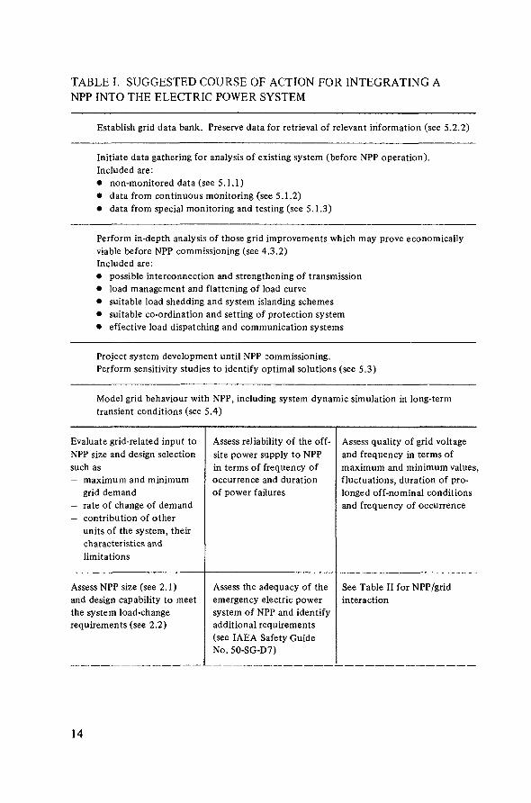
TABLE I. SUGGESTED COURSE OF ACTION FOR INTEGRATING ANPP INTO THE ELECTRIC POWER SYSTEM
Establish grid data bank. Preserve data for retrieval of relevant information (see 5.2.2)
Initiate data gathering for analysis of existing system (before NPP operation).Included are:• non-monitored data (see 5.1.1)• data from continuous monitoring (see 5.1.2)• data from special monitoring and testing (see 5.1.3)
Perform in-depth analysis of those grid improvements which may prove economicallyviable before NPP commissioning (see 4.3.2)Included are:• possible interconnection and strengthening of transmission• load management and flattening of load curve• suitable load shedding and system islanding schemes• suitable co-ordination and setting of protection system• effective load dispatching and communication systems
Project system development until NPP commissioning.Perform sensitivity studies to identify optimal solutions (see 5.3)
Model grid behaviour with NPP, including system dynamic simulation in long-termtransient conditions (see 5.4)
Evaluate grid-related input toNPP size and design selectionsuch as— maximum and minimum
grid demand— rate of change of demand— contribution of other
units of the system, theircharacteristics andlimitations
Assess NPP size (see 2.1)and design capability to meetthe system load-changerequirements (see 2.2)
Assess reliability of the off-site power supply to NPPin terms of frequency ofoccurrence and durationof power failures
Assess the adequacy of theemergency electric powersystem of NPP and identifyadditional requirements(see IAEA Safety GuideNo. 5O-SG-D7)
Assess quality of grid voltageand frequency in terms ofmaximum and minimum valuesfluctuations, duration of pro-longed off-nominal conditionsand frequency of occurrence
See Table II for NPP/gridinteraction
14
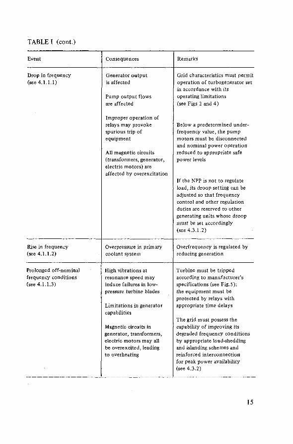
TABLE I (cont.)
Event
Drop in frequency(see 4 .1 .1 .1 )
Rise in frequency(see 4.1.1.2)
Prolonged off-nominalfrequency conditions(see 4.1.1.3)
Consequences
Generator outputis affected
Pump output flowsare affected
Improper operation ofrelays may provokespurious trip ofequipment
All magnetic circuits(transformers, generator,electric motors) areaffected by overexcitation
Overpressure in primarycoolant system
High vibrations atresonance speed mayinduce failures in low-pressure turbine blades
Limitations in generatorcapabilities
Magnetic circuits ingenerator, transformers,electric motors may allbe overexcited, leadingto overheating
Remarks
Grid characteristics must permitoperation of turbogenerator setin accordance with itsoperating limitations(see Figs 2 and 4)
Below a predetermined under-frequency value, the pumpmotors must be disconnectedand nominal power operationreduced to appropriate safepower levels
If the NPP is not to regulateload, its droop setting can beadjusted so that frequencycontrol and other regulationduties are reserved to othergenerating units whose droopmust be set accordingly(see 4.3.1.2)
Overfrequency is regulated byreducing generation
Turbine must be trippedaccording to manufacturer'sspecifications (see Fig.5);the equipment must beprotected by relays withappropriate time delays
The grid must possess thecapability of improving itsdegraded frequency conditionsby appropriate load-sheddingand islanding schemes andreinforced interconnectionfor peak power availability(see 4.3.2)
15
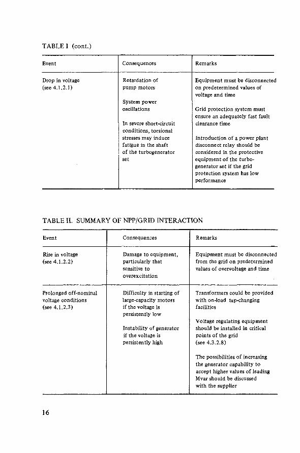
TABLE I (cont.)
Event
Drop in voltage(see 4.1.2.1)
Consequences
Retardation ofpump motors
System poweroscillations
In severe short-circuitconditions, torsionalstresses may inducefatigue in the shaftof the turbogeneratorset
Remarks
Equipment must be disconnectedon predetermined values ofvoltage and time
Grid protection system mustensure an adequately fast faultclearance time
Introduction of a power plantdisconnect relay should beconsidered in the protectiveequipment of the turbo-generator set if the gridprotection system has lowperformance
TABLE II. SUMMARY OF NPP/GRID INTERACTION
Event
Rise in voltage(see 4.1.2.2)
Prolonged off-nominalvoltage conditions(see 4.1.2.3)
Consequences
Damage to equipment,particularly thatsensitive tooverexcitation
Difficulty in starting oflarge-capacity motorsif the voltage ispersistently low
Instability of generatorif the voltage ispersistently high
Remarks
Equipment must be disconnectedfrom the grid on predeterminedvalues of overvoltage and time
Transformers could be providedwith on-load tap-changingfacilities
Voltage regulating equipmentshould be installed in criticalpoints of the grid(see 4.3.2.8)
The possibilities of increasingthe generator capability toaccept higher values of leadingMvar should be discussedwith the supplier
16
how to optimize solutions. To conduct this analysis, load studies and analyses ofthe system generation control and load restoration schemes should be performed,for which excitation characteristics, load governor characteristics and timeconstants, among other data, should be known for all the generating units of thesystem. While these data are generally readily available from suppliers in thecase of modern power plants, including NPPs, special tests and measurementsmay be required in the case of old units for which the relevant characteristicsmay no longer be available from manufacturers. Basically, the results of thispower system analysis and monitoring should include adequate information withrespect to
— grid voltage and frequency fluctuations during NPP start-up and shut-down— availability and reliability of the grid power supply at connecting points of
the future NPP to the grid- variations in power demand from the NPP, as expressed in power levels and
rate of power changes required by the system.
Having obtained this information, the utility must take the following steps:
— Identification of those operational characteristics which would be feasible tobe introduced in the selected NPP design in order to make it compatible withthe operating requirements prevailing in the system
- Setting up of adequate reinforcement in the supply and transmission systemwhich would be feasible to be introduced in order to accommodate NPPrequirements
- Establishment of appropriate operating strategies of the other units to ensuresystem stability during NPP down-times.
In taking these steps, it is advisable to discuss at an early stage any unusualproblem with potential suppliers since they may have alternatives which couldmitigate the problems.
2.4. Conclusions
Table I presents the logic of action development which leads to the identifica-tion of the system characteristics; Table II summarizes the NPP/grid interactionsand indicates possible actions to mitigate the consequences of the grid-inducedevents on the NPP. Reference is made to specific points in the text where rele-vant information can be found. Viable solutions should always be selected on acost/benefit assessment.
17
3. CHARACTERISTIC FEATURES OF NUCLEAR POWER PLANTS
3.1. Types of nuclear power plants
Proven NPP designs which are at present available for export can be broadlydivided into two categories
- NPPs with an off-load refuelling system (PWR, BWR)- NPPs with an on-load refuelling system (PHWR)
3.1.1. Reactors with off-load refuelling system
Light-water reactors use enriched uranium and have enough built-in excessreactivity to enable full-capacity operation for a period varying from 12 to18 months without refuelling. This means that the reactor needs to be shutdown at such time intervals for refuelling (depending upon the load factor andthe fuel and core design), for a period varying between 4 and 8 weeks(refuelling outage). Preventive maintenance and in-service inspection are alsodone during the refuelling outage and generally may extend the plant down-time beyond the actual refuelling time.
This requires the power system to have enough reserves for backing up thesystem during the scheduled NPP down-time period every 12—18 months; also,there should be judicious planning for these scheduled down-time periods tocoincide, where possible, with the seasonal off-peak periods.
After refuelling, the newly added fuel needs 'conditioning', which meansgradual increase of power, at a low rate and under conditions as dictated by thefuel manufacturers, for a certain period of time before nominal power can bereached. This period may vary from a few days to about three weeks. There-fore, after each refuelling, the utility has to make provisions for extra capacityto be available during fuel conditioning because the NPP will not be operatingat nominal load.
After a reactor trip, there is normally enough excess reactivity so that thereactor can be restarted without being 'poisoned out' owing to xenon transients.However, the ability of the reactor to return to normal operation without'poisoning out' can become restricted towards the end of the fuel cycle becauseof depletion of excess reactivity.
Reactors with off-load refuelling systems are more suitable for quick loadchanges over a wide range of power levels.
The task of supplying the varying power needs of the grid ultimately fallson the reactor and its control systems.2
2 Reference is made to the Guidebook on Nuclear Power Plant Control andInstrumentation, which is to be published by the IAEA.
18

3.1.1.1. Pressurized water reactors (PWRs) have good load-followcharacteristics, and the reactor is controlled through controlrods, soluble boron and coolant temperature changes.
- The power-change requirements of the daily load cycling and power rampsof up to about 10% per minute are controlled via actuations of the controlrods and by soluble boron. For NPPs with heavy regulations duty, coolanttemperature control is also available. Coolant temperature changes canminimize the wear of the control rod mechanism and power distributiondisturbances due to control rod movements.
- Fast load changes, including the utilization of spinning reserve, are handledmostly by control rods and, if necessary, by coolant temperature changes.Soluble boron effects are slowly acting. They can, however, be used tocompensate for additional control rod actuations to restore the desiredpower distribution and to compensate for xenon transients.
3.1.1.2. Boiling Water Reactors (BWRs) perform load-follow operationthrough recirculation flow control, control-rod manoeuvringand reactor pressure control.
- Recirculation flow control: This reactor power control is used during steady-state operation and daily/weekly load-follow operation. In this case, a highrate-of-power change can be performed, provided that the NPP is operatingin the upper power range.
- Control-rod manoeuvring: This control system is used for long-term reactivitycontrol in order to compensate for the fuel burn-up and for power distribu-tion control during plant start-up and total power range operation. It mayalso be prompted by requirements of daily/weekly load-follow operation andby power ramps of up to 10% of nominal power per minute when therecirculation flow is held at a constant low value.
- Pressure control: Pressure is normally regulated with the turbine throttlevalves. An increased power demand signal directly increases the reactoroutput by means of the reactor power control. The subsequent rise in steampressure is immediately compensated by opening of the throttle valves viathe pressure controller. In this control mode, the turbine throttle valveposition follows the reactor output (turbine-follow-reactor) and the steamstored in the dome is not consumed.
3.1.2. Reactors with on-bad refuelling system
Natural uranium reactors such as PHWRs do not have enough built-in excessreactivity and cannot operate for prolonged periods of time without refuelling,so an on-power fuelling system is provided. Fuelling is done almost daily and
19
the unit is not required to be shut down. However, maintenance and inspectionoutages are still necessary, but the time of shut-down can be chosen at the bestconvenience of the operator and it is generally chosen at periods of low griddemand. These reactors must be restarted soon after a trip and brought tonominal power within one hour (if the turbine is hot). However, if they cannotbe restarted within 30—45 minutes after a reactor trip (poison override time)and quickly loaded to 70% of the pre-trip power level, the built-up xenon over-whelms the excess reactivity and the reactor cannot be made critical until after30—40 hours (poison outage time).
This limitation can be alleviated by using 'boosters', which provide forextra reactivity and can therefore favourably assist plant start-up and in-corefuel cycle extension. The advantage of a higher operational flexibility should,however, be weighed against the increased fuel cycle cost.
Because of the small excess reactivity of these reactors, their load-followcapability is limited to 30-40% of nominal power (i.e. .80-50% or 100-60%).The limitation is in bringing down the power below 67% because of xenonpoisoning. The unit power regulation is obtained by adjusting the turbine loadset-point to maintain the generator output at the level demanded by the localoperator or by a generation control signal from a remote dispatching centre.
3.2. Operational modes of nuclear power plants
Although economic considerations would indicate constant load opera-tion to be the operator's first choice, other reasons may require some opera-tional flexibility and consequently justify some load-change capabilities of NPPs.
Nuclear power plants can be divided into three categories, depending upontheir degree of ability to follow the load:
- Constant-load plants. These plants normally operate at nominal load. Start-up,shut-down and load changes are very infrequent, usually dictated by NPPrequirements such as refuelling, inspections and internal restrictions.
- Scheduled load-follow plants. These plants normally operate at constant load,but may at certain predetermined times and during predetermined time inter-vals operate at partial load, according to grid requirements. These plants canfollow predetermined loading/unloading patterns, i.e. 12-3—6-3 (100-50%nominal power), which means that the plant will operate at 100% for 12 hours,then power generation is reduced to 50% within three hours, followed byoperation at this power level for six hours, and then power generation isincreased to 100% within three hours.
- Arbitrary load-follow plants. These plants are expected to meet the grid loadrequirements, including fast changes of up to 10% per minute, at any time(in the upper power range).
20

3.2.1. Constant-load plants
The constant-load plants have the following advantages and disadvantagesfrom the point of view of the designer and the operator:
Advantages:— Lower generation cost than for load-follow plants— The plant design may be basically simpler, since the thermal stresses in
materials/components are expected to be less and hence the unit may cost less— To some extent, instrumentation and control may be less extensive and/or
sophisticated (reactor start-up can be manual/semi-automatic, leaving onlysome regulation and protection to be done by automatic devices)
— The unit storage capacity (i.e. steam storage, poison addition tanks, etc.)may be less extensive.
Disadvantages:— The NPP is expected to operate at constant load and is not amenable to load
change— The plant has long start-up/shut-down times and has difficulty to come easily
to house-load or partial-load operation— The load-change requirements of the grid are to be met by the other
generating units of the system and this may require extensive backfitting(drop setting, control system adjustment, etc.) (see 4.3.1.2).
3.2.2. Scheduled and arbitrary load-follow plants
The scheduled and arbitrary load-follow plants have the followingadvantages and disadvantages:
Advantages— Shorter start-up time than constant-load plants; ability to change plant output
on predetermined schedule— Quick loading/unloading capabilities help meet the grid load-change
requirements— Ability to come to partial-load operation and house-load operation with
relative ease— Operation on automatic frequency control mode is possible.
Disadvantages— Higher generation cost than for constant-load plants— Plant components are exposed to a large number of thermal stress cycles and
may have to be designed accordingly, and hence will be more expensive— The number of fuel failures may be greater if precautions are not taken
21
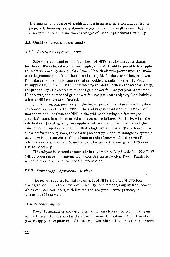
— The amount and degree of sophistication in instrumentation and control isincreased; however, a cost/benefit assessment will generally reveal that thisis acceptable, considering the advantages of higher operational flexibility.
3.3. Quality of electric power supply
3.3.1. External grid power supply
Safe start-up, running and shut-down of NPPs require adequate charac-teristics of the external grid power supply, since it should be possible to supplythe electric power system (EPS) of the NPP with electric power from the mainelectric generator and from the transmission grid. In the case of loss of powerfrom the generator under operational or accident conditions the EPS shouldbe supplied by the grid. When determining reliability criteria for reactor safety,the probability of a certain number of grid power failures per year is assumed.If, however, the number of grid power failures per year is higher, the reliabilitycriteria will be adversely affected.
In a low-performance system, the higher probability of grid power failureat connecting points of the NPP to the grid may necessitate the provision ofmore than one line from the NPP to the grid, each having a different geo-graphical route, in order to avoid common-cause failures. Similarly, when thereliability of the off-site power supply is relatively low, the reliability of theon-site power supply shall be such that a high overall reliability is achieved. Ina low-performance system, the on-site power supply and its emergency systemsmay have to be compensated by adequate redundancy so that the overallreliability criteria are met. More frequent testing of the emergency EPS mayalso be necessary.
This subject is covered extensively in the IAEA Safety Guide No. 50-SG-D7(NUSS programme) on Emergency Power System at Nuclear Power Plants, towhich reference is made for specific information.
3.3.2. Power supplies for station services
The power supplies for station services of NPPs are divided into fourclasses, according to their levels of reliability requirement, ranging from powerwhich can be interrupted, with limited and acceptable consequences, touninterruptible power.
Class-IV power supply
Power to auxiliaries and equipment which can tolerate long interruptionswithout danger to personnel and station equipment is obtained from Class-IVpower supply. Complete loss of Class-IV power will initiate a reactor shut-down.
22

LVClass-Ill buses
Rectifiers Rectifiers Regulator
Batteries
1 1
Class-I buses
SafetyCircuits
ControlLogic
Inverters
Class-I I- buses >
Motors(DC)
Motors(AC)
Instrument-ation
FIG. 3. Low-voltage A C/DC power supply free from grid disturbances.
Class-IH power supply
Alternating current (AC) power supply to auxiliaries which are necessaryfor the safe shut-down of the reactor and turbine is obtained from Class-Illpower supply with stand-by diesel generator back-up. These auxiliaries cantolerate short interruptions in their power supplies. (The total interruptiontime may be limited to three minutes with the stand-by generators which canbe up to speed and ready to accept load in less than two minutes.)
Class-H power supply (see Fig.3)
Uninterruptible alternating current (AC) power supply for essentialauxiliaries is obtained from Class-II power supply. This comprises:(a) Redundant low-voltage AC three-phase buses, which supply critical motor
loads (i.e. emergency lighting). Each of these buses is supplied through aninverter from a Class-Ill bus via a rectifier in parallel with a battery. (Undernormal operation, Class-II supply comes from Class-IV supply.)
23

LIMITED TIME
TURBINE
CONTINUOUSLY LIMITED TIME
1.00-
0.95-0.95 1.00 1.05
FIG.4. Typical loading diagram of a unit during voltage and frequency variations, valid fornominal values of voltage and frequency. S^ = nominal apparent power, UG = generatorvoltage, (7QN = generator nominal voltage, F-frequency, F^ = nominal frequency.
(b) Redundant low-voltage AC single-phase buses, which supply AC instrumentloads and the station computers. These buses are fed through an inverterfrom Class-I buses which are fed from Class-Ill buses via' rectifiers inparallel with batteries. In the event of an inverter failure, power is supplieddirectly to the applicable low-voltage bus and through a voltage regulatorto the applicable instrument bus. If disruption or loss of Class-Ill poweroccurs, the battery in the applicable circuit will provide the necessarypower without interruption.
Class-I power supply (see Fig.3)
Uninterruptible direct current (DC) power supply for essential auxiliariesis obtained from Class-I power supply. This comprises:(a) Redundant independent DC instrument buses, each supplying power to
the control logic circuits and reactor safety circuits in parallel withClass-IV supply. Each of these buses is supplied from a Class-IH bus viaa rectifier in parallel with a battery.
24
sCO
JCY
IR
EQ
UE
I*1.06
1.04
1.02
1.00
0.98
0.96
0.94
1—
1
-* 0.97
~ 1 1 1 1 1 1 1 1 1 1
10.98
1 1 1 1 1
//
l _
r~
\ i i i
0.99
2 4 6 8 10 12 14 16 18 20 32 34 36 38 40 42 86 88 90
TIME (MINUTES)
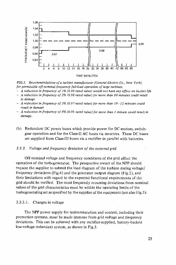
FIG.5. Recommendations of a turbine manufacturer (General Electric Co., New York)for permissible off-nominal frequency full-load operation of large turbines.- A reduction in frequency of 1% (0.99 rated value) would not have any effect on bucket life- A reduction in frequency of 2% (0.98 rated value) for more than 90 minutes could result
in damage- A reduction in frequency of 3% (0.97rated value) for more than 10-15 minutes could
result in damage- A reduction in frequency of 4% (0.96 rated value) for more than 1 minute could result in
damage.
(b) Redundant DC power buses which provide power for DC motors, switch-gear operation and for the Class-II AC buses via inverters. These DC busesare supplied from Class-Ill buses via a rectifier in parallel with batteries.
3.3.3. Voltage and frequency deviation of the external grid
Off-nominal voltage and frequency conditions of the grid affect theoperation of the turbogenerator. The prospective owner of the NPP shouldrequest the supplier to submit the load diagram of the turbine during voltage/frequency deviations (Fig.4) and the generator output diagram (Fig.2), andtheir limitations with regard to the expected functional requirements of thegrid should be verified. The most frequently recurring deviations from nominalvalues of the grid characteristics must be within the operating limits of theturbogenerating set as specified by the supplier of the equipment (see also Fig.5).
3.3.3.1. Changes in voltage
The NPP power supply for instrumentation and control, including theirprotection systems, must be made immune from grid voltage and frequencydeviations. This can be achieved with any rectifier-supplied, battery-backedlow-voltage redundant system, as shown in Fig.3.
25
Frequency changes do not affect this power supply. Different limitationsapply to the permitted voltage deviations of the power supply to the plantelectric equipment during start-up and normal operation.
Critical problem areas in running NPPs outside the prescribed limits ofvoltage include: (a) start-up of motors, (b) power level and torque of motors,(c) pump flow, (d) valve drives, and (e) setting of operating limits of relays.
The permitted deviations in standardized design may differ from one supplierto another and must be carefully verified by the prospective owner of the NPPwith regard to the currently prevailing conditions of his gri'd.
Typical supplier-guaranteed limits for correct operation at start-upconditions may include:— high-voltage motors: down to 75% of nominal voltage— low-voltage motors: down to 70% of nominal voltage— valve drives: down to 80% of nominal voltage.The prospective owner of the NPP should also clarify whether such limits includethe overall performance of the aggregate (motor and pump).
Short-time voltage drops as reported above can be tolerated if high-capacity motors are started. For bus bars of diesel back-up generators, a dropof 15—20% is generally acceptable. However, continuous operation of large-capacity fully loaded motors at such levels is not recommended. Off-nominalvoltage conditions of prolonged duration can be compensated by on-load tapchangers; usually, these compensate for the following deviations from nominalvalues:
+ 10% for normal transformers± 15% for stand-by grid transformers.
If larger deviations are expected, the capability of the turbogenerator will haveto be discussed with the equipment manufacturer and guaranteed by him.
3.3.3.2. Changes in frequency
Nuclear power plants of standardized design can normally operate withgrid frequency deviations which are expected to remain within 1% of the ratedfrequency. Deviations of up to 5% of the rated frequency may be permittedfor short times (see Fig.5). Under these conditions, restrictions in NPP opera-tion automatically initiate a power run-back (see Section 3.4.3) via a speciallimit control system. When the frequency drops to below 5% of the rated fre-quency, the turbine must be tripped if the system cannot be islanded (seeSection 4.1.1.3) and the reactor power brought down to a safe level. Beyond7% of the rated frequency, the reactor will be scrammed (93% of coolant pumprated speed — see Section 4.1.1.1). Availability of reactor set-back capabilityis an important feature which enables the reactor, during frequency variations,to maintain its output and to come back to nominal power quickly after thedisturbance has been cleared.
26
3.4. Operational characteristics of nuclear power plants
The design of a NPP has its own characteristic operating features. The manu-facturer of the equipment should be requested to clearly display the basic designfeatures of the plant to be supplied in order to identify improvements necessaryto strengthen the grid performance for safe operation of the NPP. This is evenmore important when the plant is the first nuclear unit and likely the largestone in the system.
During its operational life, the NPP must serve the load-change require-ments of the grid and must therefore be able to feature adequate operatingperformance. In a low-performance grid, the ability of the NPP to pick up loadwithin a short time may be of particular relevance. The time necessary to reachnominal power from zero power primarily depends on the temperature level inthe NSSS and BOP. This time also depends on the NPP type and design andmay thus vary from one manufacturer to another. In this respect and in theinterest of the NPP owner, it is important that the start-up time be guaranteedby the equipment supplier and adequately demonstrated by documentedoperating experience of an existing NPP of the same size and type as theenvisaged NPP.
The start-up of a NPP basically comprises the following major steps:
— Warm-up of primary and secondary systems from cold conditions (lowpressure, low temperature) to warm conditions. This operation is necessaryafter a prolonged down-time of the plant (refuelling and/or maintenance).
— Start-up from warm (no power) to low-power-range conditions. This opera-tion is required when the plant re-starts soon after a reactor trip or plantshut-down to zero reactor power. The power level is brought to a minimumvalue, from which quick plant loading in the power range is possible.
— Load pick-up in the power range. This operation is performed when loadingthe plant to nominal power and during any period of scheduled load-followoperation.
To respond to the load requirements during operation in the power range,the plant may have to perform rapid power changes of limited magnitude (steppower changes) and/or slow power changes of large magnitude (ramp powerchanges). Normally, a power change of limited magnitude can be performedwith a high gradient, and a large power change can be performed with a lowgradient. Moreover, the permissible gradient depends also on the power rangeat which the power change is performed. The following example will assist inclarifying these points.
— Step power changes at a rate of 1% of nominal power per second may bepermitted in the range of up to 10% of nominal power (i.e. from 90% to 100%of nominal power: frequency control band), with the restriction that, after
27

a step larger than ± 5%, a dead-time of a few minutes must elapse before thenext step, to permit the power control to take action.
- Ramp power changes can be performed with different rates of power change,depending on the power range at which they are performed. Therefore, 2%per minute over a range of 80% of nominal power, 5% per minute over a rangeof 50% of nominal power, and 10% per minute over a range of 20% of nominalpower are generally permitted.
3.4.1. Start-up from cold reactor and cold turbine to nominal power operation
This operation takes a relatively long time and is necessary after everyprolonged shut-down of the NPP. The guaranteed start-up time for commercialNPPs from cold conditions to 100% of nominal power may be up to 25 hoursand even longer (for constant-load plants). The corresponding time for a fossil-fuelled power plant is 2 -5 hours.
For LWRs, after each refuelling outage, 'conditioning' of the new fuel isneeded, which takes up to three weeks (depending on the fuel/NPP manufacturer),during which the reactor power is raised at a slow rate to nominal power (seeSection 3.5.1). Once the fuel is 'conditioned', using the method recommendedby the fuel/reactor manufacturer, subsequent start-ups from cold conditions canbe performed in the time range mentioned above. During start-up, the NPPneeds reliable power supply from the grid to the amount of 5—7% of the ratedunit output at stabilized voltage and frequency conditions.
3.4.2. Start-up from hot reactor and hot turbine to nominal power operation
If the NPP has tripped and is in a position to be re-started, this should bedone in the shortest possible time, while the reactor and the turbine systemsare hot. For LWRs, this takes 1-3 hours, depending on the plant I&C designand its degree of automation. PHWRs must be brought to 70% of the pre-trippower level within 30—45 minutes, in order to avoid poison outage aftera trip. The corresponding time for a fossil-fuelled power plant is 1 - 3 hours.If the plant is re-started after a period during which the reactor has been kept athot stand-by but the turbine has cooled down, a more cautious start-up has tobe performed since the limitations imposed by the manufacturer on the BOPhave to be observed; it may take about 7—16 hours to raise the plant outputto 100% of nominal power, depending on the amount of turbine cool-down.Controlled shut-down of the reactor from 100% power or below to subcriticalconditions (hot stand-by) can be carried out within a few seconds to up to2 hours, depending on plant design. During shut-down times of short duration,the reactor is kept hot in order to enable quick plant re-start.
28

3.4.3. Reactor power set-back capabilities
There are several reasons why NPPs may have to resort to run-back topartial load ratings. These reasons may be external (originating in the grid) orinternal (as a consequence of equipment malfunction in NPPs).
3.4.3.1. External reasons for NPP set-back operation
Nuclear power plants may resort to a quick run-back to partial power outputbecause of some grid-induced critical event. Such events are listed below.
- Large load drop in the grid as a consequence of upset system conditions leadingto system islanding. The NPP may be required to run back to 80%-60% ofnominal load in order to meet the balance between the generation and the loadin the islanded system. The rate-of-power changes and the maximum valuesfor step load shedding depend on NPP design characteristics, load require-ments and characteristics of other generating units in the islanded system,and must be taken fully into account when the islanding scheme is engineered.
- Isolation of the NPP from the grid, with the NPP only serving reduced localloads. The NPP may be required to run back to 40% or less of nominal powerin order to avoid a trip and to maintain generation. The minimum design steamflow to the turbine will govern the minimum acceptable power level.
- Severe disturbance, such as grid power failure. The NPP may be required tocut off all external ties, to run back to supply its own house load, and to beready to accept load again up to nominal power soon after the disturbancehas been cleared. During house-load operation, only about 5% of nominalpower is generated by the generator while the reactor power is maintained ata higher level. When the disturbance is a grid-induced event, the reactor can beoperated at up to 30% of nominal power if automatic control is preferred(MILAC), or even at a higher power level (MILQUICK) for quick return to powerif the disturbance is anticipated to be of short duration (see Section 3.4.3.3).
In the house-load condition, it should be possible to operate a unit havinga unit-bound auxiliary system supply for several hours at rated speed, with theunit only supplying its own auxiliary systems. The voltage regulator must ensurethat the voltage of the isolated auxiliary supply system remains within the per-missible limits. During house-load operation, the NPP is able to synchronizewith its own means and to be quickly reloaded to nominal power. Theseoperating features enable the NPP to be independent from the grid and to keepthe main pumps running (normally, the emergency electric power system withdiesel set does not enable the start-up of the large primary coolant pumps andthe boiler feedwater pumps).
29

3.4.3.2. Internal reasons for NPP set-back operation
Nuclear power plants may be requested to resort to intermediate safe powerlevels because of malfunctioning of internal plant systems and/or components; thisincludes:
— trip of one of the subsystems, such as reactor cooling, feedwater, condensate,condenser cooling (as permitted by licensing regulations)
— component failure or overheating— control malfunctioning.
For each case, a distinctly defined active measure is provided (sequence orredundant limit controls) by the relevant system design, including run-back toacceptable operating conditions. The operator must closely monitor the numberof such occurrences and the different levels at which the reactor power has beenset back, because these operational modes erode part of the plant life enduranceand their cumulative effects during the plant life must not exceed those assumedin plant design (see Section 3.5.3) or else the guaranteed life of the plant willbe shortened.
3.4.3.3. Minimum load with automatic control (MILAC) andminimum load for quick return (M1LQUICK)
MILAC is defined as the minimum load value at which the plant can beoperated without manual control. Values of between 15 and 30% of nominalpower are possible for modern LWRs, depending mainly on turbine design andreactor control stability.
In MILQUICK conditions, the reactor is kept at its highest possible powerlevels, depending upon condenser by-pass capacity, whereas the generator is runat a low power level. This performance is requested when, after disconnectionof the NPP from the supply system, the load dispatching centre anticipates thatthe fault is of short duration, and plant re-synchronization to the grid and aquick loading signal are expected within a short time. Under these conditionsthe turbine could possibly be returned to full load very quickly, depending onthe amount of cool-down that has occurred. If the turbine has cooled down,quick return to load is not permitted because of thermal limitations in theturbine (see Section 3.5.3).
During operation at intermediate reactor power levels while the generatorproduces the house load, the excess steam is dumped to the steam dump con-denser or to the atmosphere if this is permitted by licensing regulations and ifadequate supply of demineralized water is available.
In selecting the NPP load rejection capacity, utmost care must be exercisedin appraising the economy of a more flexible operating performance against the
30
design extra-cost this may imply. In this respect, it must be considered thatload rejection capacity may be designed for conditions such as:- approximately 80% of the rated main steam flow for a high steam-dumping
capacity without any set-back functions- approximately 50% of the rated main steam flow for a moderate steam-
dumping capacity with a set-back function to, say, 60% of nominal powerin about 10 to 20 seconds.
Set-back capabilities to lower power levels are also possible, even to fullload rejection. However, it must be considered that, if dumping steam to theatmosphere is not permitted, then dispatching the steam to a special dumpcondenser may involve:- additional cost of the equipment- additional design complexity- additional material stress problems- additional cost for redundancy to ensure reliable functions.
For PHWRs, a large steam by-pass capacity is more advantageous. Steamdumping provides PHWRs with good capabilities for quick return to full powersoon after a turbine trip.
If the low-power operation periods are of short duration, it may be advan-tageous for these plants to dump steam to the condenser or to the atmosphereduring the entire period and to keep the plant running at high reactor powerlevel. While this appears to be wasting energy, the cost of this energy loss mustbe balanced against the cost of providing continuous excess reactivity in thecore to permit load-follow operation.
3.5. Limitations of load-change capabilities of nuclear power plants
If the NPP is called upon to perform load-follow operation, its ability ofchanging the output to meet the system load-change requirements depends upon:- plant design characteristics- past operational plant history- magnitude of the load change required- rate of the load change required- plant power level at which the load change is performed.
Operating experience of NPPs in the load-follow mode is available, but foreconomic reasons these plants are used today primarily for base load. However,the inclusion of load-follow capabilities in the guaranteed operating performanceis regarded at present to be an important requirement of modern NPP design.Such load-follow capabilities are, however, subject to certain limitations imposedby the equipment manufacturers.
31
3.5.1. Restrictions in output changes due to fuel performance
In the past, some of the fuel failures associated with load cycling operationof NPPs were due to insufficient knowledge of designers, manufacturers andoperators regarding fuel performance. Faults were mainly due to the stressesinduced by operators' actions which were permitted because of lack of properunderstanding of pellet/clad interactions. According to present knowledge, fuelfailures depend upon:— fuel design— process of manufacture— water chemistry— control strategy— mode of operation.
As operating experience has accumulated and better understanding of fuelbehaviour has been achieved, more confidence is acquired in the operating perfor-mance of modern well-designed fuel elements featuring daily or weekly load cyclingin a manner approved by the fuel manufacturer and ensured by an established andwell-proven control strategy. Fuel failure may develop because of combinationsof all of the following occurrences:
— After refuelling, the local power density in the fuel is raised too quickly fromlow to high values
— The fuel has previously been kept for a long period (weeks) at low powerdensity
— The local power density is raised above a certain 'conditioning' level whichdepends upon the fuel burn-up. (For some fuel designs this may be fromabove 600 W/cm for fresh fuel to 350 W/cm for fuel with high burn-up.)
To avoid the above-mentioned causes of fuel failure, 'conditioning' of thefresh fuel after each refuelling (in LWRs) may be requested for guaranteed fuelperformance. For conditioning the fuel, the rate of power increase soon afterreactor re-start following each refuelling is limited to approximately 0.5-2% ofnominal power per hour. Therefore, for a period of three days to about threeweeks, nominal power will not be available from the NPP. Consequently, theload dispatcher should make suitable provision to cater for the load require-ments of the system during these restrictions of NPP generation by means ofadequate loading strategies for the other generating units of the system.
Fuel failure which may be provoked by the first ramp of a non-conditionedfuel can be avoided if:— start-up after refuelling is performed slowly— quick ramps after long periods of partial load operation are avoided— large changes in fuel power density distribution are avoided.
32
If the NPP is required to change its power output quickly, the decisionregarding permissible local power distribution becomes complex and is beyondthe capability of a manually operated control system; it may then becomenecessary to use a redundant, automatic, computer-assisted control system.
3.5.2. Restrictions in output changes due to reactivity limitations
For maintaining constant reactor power, a reactivity balance must be kept.For increasing the power level, it is necessary to add positive reactivity, and forlowering the power level, negative reactivity must be added.
In some conditions, however, the power rise may be limited because of theinability to insert positive reactivity as required, since all absorber rods in thereactor control system are withdrawn and no other reactivity control means areavailable; the reasons for this are:— control elements cannot be withdrawn because operating limits such as high
local power density are reached— all reactivity changes by control elements and other means are needed for
transient xenon poisoning— storage tanks of liquid control means (boric acid) are full because of control
actions in previous load changes.
Limitations in excess reactivity do not have any destructive or harmfuleffect on the NPP but decrease the operational flexibility and sometimes mayeven lead to subcritical reactor conditions if xenon poisoning effects cannot beovercome.
3.5.3. Restrictions in output changes due to thermal stresses in materials
Thermal stresses in materials are dependent on the range and rate of powerchanges and, since the effects are cumulative, the total number of power cyclingsperformed during the lifetime of components.
Such stresses may initiate damages in critical points of the NPP. Some ofthese damages have been identified by NPP designers to be generally located in:- pipe walls- thick walls of components— nozzles of large components and adjacent areas— tanks of small mass-to-flow ratio— points of large temperature changes- welded joints of dissimilar materials.
33
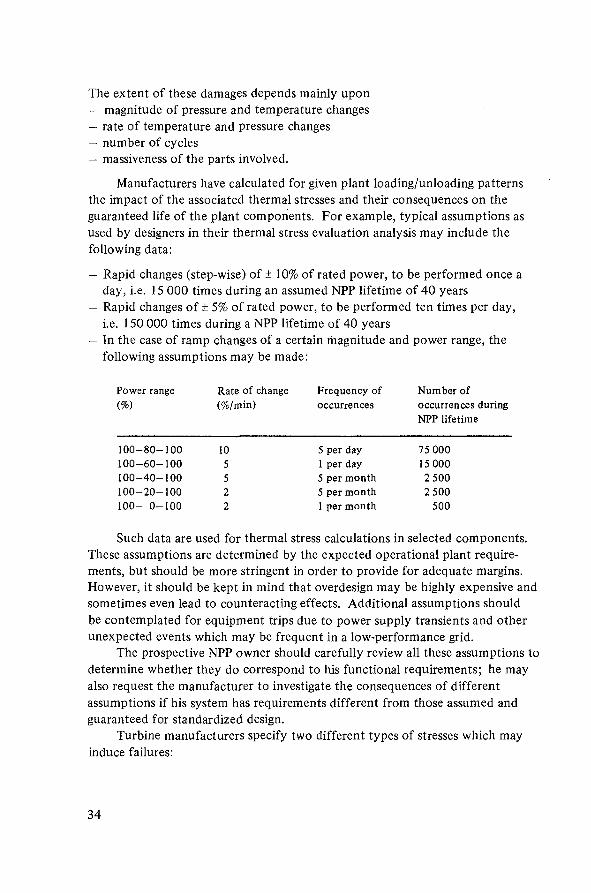
The extent of these damages depends mainly upon— magnitude of pressure and temperature changes— rate of temperature and pressure changes— number of cycles— massiveness of the parts involved.
Manufacturers have calculated for given plant loading/unloading patternsthe impact of the associated thermal stresses and their consequences on theguaranteed life of the plant components. For example, typical assumptions asused by designers in their thermal stress evaluation analysis may include thefollowing data:
— Rapid changes (step-wise) of ± 10% of rated power, to be performed once aday, i.e. 15 000 times during an assumed NPP lifetime of 40 years
— Rapid changes of ± 5% of rated power, to be performed ten times per day,i.e. 150 000 times during a NPP lifetime of 40 years
— In the case of ramp changes of a certain magnitude and power range, thefollowing assumptions may be made:
Power range Rate of change Frequency of Number of(%) (%/min) occurrences occurrences during
NPP lifetime
100-80-100 10 5 per day 75 000100-60-100 5 1 per day 15 000100-40-100 5 5 per month 2 500100-20-100 2 5 per month 2 500100- 0-100 2 1 per month 500
Such data are used for thermal stress calculations in selected components.These assumptions are determined by the expected operational plant require-ments, but should be more stringent in order to provide for adequate margins.However, it should be kept in mind that overdesign may be highly expensive andsometimes even lead to counteracting effects. Additional assumptions shouldbe contemplated for equipment trips due to power supply transients and otherunexpected events which may be frequent in a low-performance grid.
The prospective NPP owner should carefully review all these assumptions todetermine whether they do correspond to his functional requirements; he mayalso request the manufacturer to investigate the consequences of differentassumptions if his system has requirements different from those assumed andguaranteed for standardized design.
Turbine manufacturers specify two different types of stresses which mayinduce failures:
34

(a) Mechanical stresses. These depend upon the magnitude and frequency ofmechanical vibrations. Most common are strong vibrations due to resonantspeed of the turbine which may induce failures in the low-pressure turbineblades (see Section 4.1.1.3). Recent investigations of the dynamic behaviourof large turbogenerator sets have shown that also torsional vibrationsinduced by short circuits of long duration in the vicinity of the power plantcan induce shaft fatigue and reduce the effective life of the unit.3
(b) Thermal stresses in materials associated with plant start-up and load-changeoperation (a case in point is the differential heating of the turbine casingwhich must be appraised since too rapid admission of steam may poseproblems). These stresses, depending on load change, rate of change andcumulative number of occurrences, affect the life of the turbine. Of course,the problem of thermal stresses in materials also exists in other plant com-ponents. If different suppliers have been chosen, the prospective ownershould verify that the assumptions made for the NSSS are consistent withthose made for the BOP.
The results of a turbine stress analysis as performed by a manufacturer forthe assumptions indicated are listed below.
Load change(%)
100-80-100100-60-100100-40-100100-20-100100- 0-100
Start-up (cold)/shut-down
Rate of change(%/min)
101055
5 - 2
As permitted,only bystart-up/shut-downcontrol devices
Number ofoccurrences
10s
1.5 X 10⁴
1.2 X 10⁴
1000400
200
Total
Turbine lifetimeconsumed (%)
11680104
6
> 100%
3 It has been found that, even in the case of a three-phase fault, the torsional stress has noeffect if the fault is cleared within 150 ms. Stressing of the stator winding is also low in suchcases. This calls for quick-acting grid protection equipment. In a low-performance grid, thisrequirement may not be satisfied, so that fault clearing times in excess of 150 ms as well asfault clearance in the second step of grid protection (i.e. as a consequence of a circuit breakermalfunction) are often encountered. In these cases, the only effective measure for avoidinghigh torsional stresses is to disconnect the turbogenerator set from the grid. Immediatere-synchronization can then be effected. The necessary protective equipment for this purposeis a power plant disconnect relay.
35
The results show that, in this case, the combined effects of all assumedthermal stresses may shorten the life of the turbine compared with the plantlifetime and that the cycle 100-40-100 is the most critical. Therefore, thefollowing points should be considered:
— It may become imperative to change the assumptions and to take these changesinto account in operating practice so that the turbine life consumed by thermalstresses remains below 100% during the expected lifetime of the plant.
- The design may need modifications in order to ensure the ability of theturbine to withstand all thermal stresses induced by the assumed mode ofoperation.
In any case, techniques of failure prediction (ultrasonic tests, radio-graphy, etc.) for pre-warning the operator should be incorporated in the designand strictly monitored by the operator.
It is important that the final judgement regarding the ability of the envisagedNPP to perform load-follow operation be based on the results of theoreticalcalculations and also that the manufacturer be in a position to guarantee thedesign characteristics on the basis of actual operating experience from an existingNPP of the same type and in the same size range.
4. INTERACTION OF GRID AND NUCLEAR POWER PLANT
4.1. Influence of the grid on the nuclear power plant
Transients originating in the grid lead to transients in the NPP in a chain-like fashion, the effect of which, depending upon the severity of the disturbance,may lead to islanding of the NPP or even to tripping of the reactor. Suchdisturbances adversely affect the performance and life of the plant. Theperformance of the NPP (availability, life, increased maintenance effort) isaffected by the frequent grid disturbances prevalent in low-performance systemsas well as by the increased incidence of emergency situations arising therefrom,and in this context a study of the dynamic interaction between grid and NPPbecomes extremely important.
Careful evaluations should lead to a concept of the proper NPP design, thepossible addition of equipment and those system operation strategies which willmost economically ensure the safe operation of the NPP.
In a low-performance system, improvements of grid characteristics aregenerally necessary. If it is not technically possible or economically viable tocompensate for all grid deficiencies, the conclusion may quite simply be that thesystem just cannot support the operation of a NPP.
36
4.1.1. Effects of frequency change on NPP operation
The frequency in a grid can change quickly or slowly. It can persist at off-nominal conditions or it can come back to a nominal value after a sharp change.If the frequency has fallen because of a loss of generation, the grid can stillrecover if there is adequate spinning reserve. If spinning reserve is not adequate,remedial measures like load shedding and/or system islanding have to be resortedto in order to improve the frequency. Basically, any change in frequency affectsNPP operation through the speed governor of the turbogenerator and through achange in the speed of pumps delivering flows to the reactor and secondarycoolant circuits.
4.1.1.1. Sharp drop in frequency
When the frequency drops, the turbogenerator assumes load, dependingupon the load governor droop setting and the frequency deviation. Theresulting mismatch of reactor power produced and power drawn from thereactor causes an intervention of the control system. Coolant circulation pumpmotors are also affected. On a drop in frequency, the output flow of the pumpswill come down as the developed head is proportional to the square of thespeed/frequency, and the process system may be disturbed in PWRs by achange in primary coolant average temperature, in BWRs by void distribution,and in PHWRs by change of reactor delta T. Measurements of reactor powermay be affected if they are not supervised by flow signals. In some PHWRdesigns, large-capacity pump motors are provided with high-inertia flywheelsto improve the coast-down time of the pumps in accident conditions and areprotected by under-power relays. On a sharp drop in frequency — although thedrop may be of small magnitude — the motor may change from the inductionmotor mode to the induction generator mode and come back to the inductionmotor mode, which may result in operation of the under-power relays and aconsequent spurious reactor trip. In this case, the operation of under-powerrelays should be interlocked with under-frequency relays set at predeterminedfrequency values. If the frequency drop does not go below the setting value,the under-power relays will not trip the pump and hence no spurious reactortrip will take place.
In some LWR designs the use of under-power relays is not contemplated,but the reactor will be scrammed if the speed of the main coolant pumps dropsbelow 93% of its rated value (see Section 3.3.3.2).
If the drop in frequency is accompanied by a large change of reactive powerinducing overvoltage conditions, the overexcitation relays intended for protec-tion of generators and transformers may operate. In the case of overexcitation,the transformers may be more affected since they are normally designed to
37
operate approximately at the knee-point of their magnetic saturation charac-teristic at nominal voltage.4
4.1.1.2. Sharp rise in frequency
Tripping of a tie line disconnects some load from the grid and the gridfrequency suddenly rises. Because of the frequency rise, the turbine speedgovernor closes the throttle valves which reduce the power in the turbine; withthe reactor power level unchanged, it is now greater than that drawn by theturbine. The mismatch causes transient overpressure in BWRs, and over-temperature and overpressure in PWRs. Excess steam is dumped to the rejectcondenser or to the atmosphere, if permitted, and the reactor power is broughtto the level of turbine demand by the intervention of the control system.
Pumps develop more head and hence the increased flows affect the feed-water control system and the primary pressure and temperature control. Thermalstresses may develop in critical components, following admittance of increasedcold water inflow, unless appropriate over-frequency protection is provided.The introduction of over-frequency relays with an appropriate time delay toseparate the NPP from the grid helps to avoid possible damage to the equipmentin persistent over-frequency conditions. Moderate over-frequency conditionscan generally be easily controlled by reducing generation and as such do notpose any problems. Automatically disconnecting the NPP from the grid maytherefore be warranted only in severe conditions. Speed limiters are normallyprovided in the turbine control system to prevent turbine overspeed.
4.1.1.3. Prolonged off-nominal frequency conditions
In the case of insufficient generating capacity and inadequacy of the load-shedding schemes, the utility may be forced to operate at a frequency levellower than nominal over an extended period of time. Turbine manufacturersspecify stringent limitations on off-nominal frequency operation of the turbines.Because of vast improvements in the materials and the construction of blades,the low-pressure turbine buckets are long and slender. The vibration stress levelin the blades at rated speed is well below the endurance limit. However, at off-nominal frequency conditions, the blades may come within the domain ofresonant speed at which unacceptably high vibration may develop, inducing
Modern power transformers are designed to operate at high flux densities which arenear to the saturation value. Depending upon their thermal time constant, the power trans-formers have some overexcitation capacity. Flux — a measure of excitation — is convenientlyexpressed by the ratio of per-unit voltage to per-unit frequency. Hence, an increase of voltageor a reduction of frequency is a cause of over-fluxing. Suitable protection should beconsidered when large frequency and voltage deviations from nominal values are expected.
38
blade failures. Figure 5 shows the typical recommendations of a turbine manu-facturer. It can be seen that modern turbines suitable for high-performancegrids can operate only for a few minutes at a frequency below 100% of therated value. Such operations have a cumulative effect and are permitted onlyfor a certain total period over the life of the unit. Although designing theturbine to operate continuously within a more liberal frequency range withoutdeleterious effects would be a significant advantage for operators of low-performance systems, such design modifications are difficult and oftenimpractical to obtain since proven and guaranteed equipment manufacturingis standardized to a large extent. Therefore, upon frequency drop, the NPPmust be disconnected from the grid at predetermined frequency values withgraded time delays if in the meantime the system frequency has not recoveredby virtue of islanding and/or load-shedding schemes. Similarly, large-capacitypump motors should be designed so as to be safely operated until certain low-frequency limits as specified by the manufacturers are reached. Beyond theselimits, means should be provided to adequately protect these motors. Large-capacity motors with the capability of starting and running at frequencyconditions beyond the standardized limits will require a special design whichmay prove very expensive, inefficient and with limited guaranteed reliability.
4.1.2. Effects of voltage change on NPP operation
Off-nominal voltage conditions at various points of the grid are mainlydue to the following reasons:
- Inability of the grid protection system to quickly clear transmission linefaults
- Long transmission lines without intermediate power stations- Lack of voltage control equipment, such as synchronous condenser and
static capacitors- Absence of on-load tap-changing transformers- Insufficient capacity of the transmission lines to carry the peak load.
Better grid voltage conditions are generally achieved by adequate voltage controlequipment at critical points of the grid and by good meshing in the transmissionnetwork. Appropriate siting of the generating units is also effective in main-taining a good control of the grid voltage.
4.1.2.1. Sharp drop in voltage
A rapid drop in voltage (voltage dip) is mainly due to an electric fault ona transmission line(s). The extent of the dip depends upon the proximity andnature of the fault, and upon the sensitivity of the automatic voltage regulator
39
(AVR) equipment of the generators connected in the grid.5 The duration ofthe dip depends on the speed of the protective relays and their co-ordinationas well as on the circuit breaker characteristics and their speed of operation.During sharp voltage dip conditions, all connected motors will be retarded. Themagnitude of the retardation is determined by the voltage dip and its duration,the characteristics of the load, and the mass moment of inertia of the motor-pump assembly.
To mitigate the consequences of a drop in voltage, the protection systemof a low-performance grid should be studied and improved by:- introducing fast-acting fault-detecting relays with good co-ordination- introducing fast-acting breakers for quick isolation of faults- introducing auto-reclose features on the breakers.6
4.1.2.2. Sharp rise in voltage
If the grid loses a large load and the NPP remains connected with long,lightly loaded lines at the remote end, the grid voltage may rise sharply. Theeffect of high voltage can be deleterious to equipment such as transformers andlarge-capacity motors which are sensitive to overexcitation. The electric generatormay become unstable. Adequate overvoltage and overexcitation protection ofthe electric equipment should be available, as specified by current electricalstandards.
4.1.2.3. Prolonged off-nominal voltage operation
When the voltage control equipment is inadequate, it may not be possibleto maintain the same voltage at different points of the grid at all times, andpoor voltage conditions may develop and persist over extended periods.
Prolonged high voltage on the grid may force the generator to acceptlarge values of leading reactive power (Mvar) and it may become unstable.In certain cases, it may trip on overexcitation (see Fig.2). Prolonged low voltageon the grid may create problems in starting and running large-capacity motorsof the NPP. Some motors are provided with flywheels and have a relativelylong start-up time. If the voltage is too low, the starting torque may become
5 During power system disturbances, fast-responding voltage regulators can adverselyaffect the recovery of the system as they can cause an overvoltage condition. One methodof limiting uncontrolled interaction between all generators on the grid including the NPPis to dampen the excitation response during a transient condition. Power system stabilizersare available in modern excitation systems for this purpose; however, these are known toinduce undesirable oscillations and care must be exercised when they are adopted.
6 Single-phase high-speed reclosure is particularly effective. Three-phase high-speedreclosure may cause problems of torsional stresses in the turbine shaft if the fault-clearingtime of the grid protection system is too long (see Section 3.5.3).
40
insufficient and the motor may not come up to full speed and eventually tripon stall protection. If the pump motor is operating, it may trip on overload.7
If during pump start-up the pump trips owing to overload, an immediate re-startis harmful to the pump motor. Sufficient time must be allowed between sub-sequent start-ups in order to allow for adequate cool-down of the pump motor.
4.2. Influence of the nuclear power plant on the grid
Because of its relatively large size the NPP, while operating, plays animportant role in stabilizing a low-performance grid. In addition, NPPs havecharacteristics which permit a relatively high rate of power change whenoperating at reduced power in the upper power range. This operating featureof NPPs can therefore be used profitably by the load dispatcher in providingfor generation control during contingency operation when the NPP is operatingat less than nominal power.
Conversely, during NPP down-times in a low-performance grid, generationcontrol becomes a difficult task for the load dispatcher. An outage of the NPPwill cause a substantial loss of generation of both MW and Mvar for the grid.The larger the size of the NPP, the higher will be the loss and the investmentsfor larger spinning capacity and reactive power compensating equipment. TheNPP size selection is of great technical and economic significance. The gridmust have enough reserves to ensure system frequency stability during NPPdown-times (refuelling and/or maintenance), and adequate loading strategiesfor the other units feeding into the system must be established to assist duringscheduled outages.
4.3. Improving the nuclear power plant/grid interface
To achieve a smooth integration of the NPP into the system, the prospectiveowner of the NPP should verify that adequate operating capabilities, which areresponsive to his functional requirements, are included in the NPP design; heshould also consider improvements which would be economically feasible to beintroduced in the grid to permit safe operation of the NPP.
4.3.1. Nuclear power plant design
The power set-back capabilities and the ability to resort to, and to exten-sively operate at, house-load conditions are important features of a NPP intended
7 Running electric motors tend to maintain a constant megavolt ampere (MV-A).A voltage reduction will cause a current increase.
41

for a low-performance grid. These operating characteristics should be demon-strated, not only by design calculations but also by extensive operatingexperience with a NPP of the same type and size, built by the potential supplierof the envisaged NPP. During commissioning of the NPP, acceptance testingshould demonstrate the 100% load rejection capability without turbine trippingon overspeed.
A point to be considered is that, upon a grid disturbance, if the NPP isimmediately disconnected from the grid, its loss of generation is likely to add tothe already disturbed conditions of the grid. To help maintain the stability ofthe system, the NPP should therefore be made as available as possible withoutcompromising its safety. In this respect, all parameters which initiate a powerset-back and/or a reactor trip should be critically studied and, as far as possible,their measurement should be made immune from grid-induced events by ade-quate delay equipment; thus it can be seen whether the NPP can sustain thedisturbance, first by resorting to intermediate power levels and then to house-load operation, to prevent damage to equipment; a reactor trip should be thelast means of ensuring safety.
Uninterrupted operation of the NPP is important for the system, more soat times of upset conditions when the grid needs the service of the NPP moreand when its outage is likely to cause difficulty in maintaining the frequency.
4.3.1.1. When the voltage and frequency of the external grid vary, it shouldbe possible to operate the turbogenerator set at the conditions indicated by itscharacteristics (see Figs 2,4,5). Margins for design modifications are verylimited, since manufacturing of important equipment is to a large extentstandardized. In a low-performance system, therefore, the grid characteristicsand the performance of the protective devices have to be improved in order tomeet the operational requirements of the turbogenerator set. Also, the designof high-capacity motors for operating conditions other than those normallyprescribed by manufacturers is very special, expensive and inefficient, and it isnot advisable to introduce such motors since their performance may not beguaranteed. Moreover, extending the start-up and running capabilities of suchmotors at excessively low voltage and frequency conditions may result incounter-effects:
— Increasing the torque of the motors to improve start-up performance inunder-voltage conditions will have the effect of drawing an excessively highcurrent and may create problems regarding transformers
— Enabling motors to deliver full pump flow at under-frequency conditions mayprompt the operator to operate improperly at nominal power under degradedgrid conditions.
4.3.1.2. If the NPP is not to participate in frequency control and/or loadregulation, the speed and/or load governor of the turbine can be made insensitive
42
to a certain frequency band and thus the turbine will no longer control thefrequency. Also, within this frequency band, the generator output is fullydependent on reactor power/pressure and not on frequency. Above the pre-scribed frequency band, the speed governor assumes control and can send thesteam partially or wholly to the condenser, directly by-passing the turbine.At the same time, reactor power may be reduced by the reactor regulatingsystem to match the turbine load demand. Below the prescribed frequency band,the NPP may be islanded, together with a part of the system, and its generationbrought down to safe power levels, or the NPP may even be separated from thesystem and operated at house load if the equipment can operate safely at theseconditions for an extended period.
An alternative is to have a speed governor with variable droop setting and toset it at a droop level higher than that of other generating sets connected to thesystem. This is a compromise between no participation in frequency control, asin the first case, and full participation in frequency control, as in other units ofthe grid. Load limiters can be set accordingly at a predetermined value so that,on decreasing frequency, load assumptions are limited to the pre-set value. Onincreasing frequency, the speed governor will come into force and will reject loadupon frequency rise and droop setting, and participate in load/frequency control.
It must be noticed that both alternatives, especially the first one, impose aheavier frequency control and load regulation duty on the other generating units.Their droop setting must be fixed at a value lower than that of the NPP and thismay require careful appraisal of extensive backfitting.
4.3.2. Grid characteristics
For correct integration of a NPP into an existing power system, a numberof actions should be taken in order to find out how the special requirements andoperating characteristics of the selected NPP design can be accommodated bestby the existing system for reliable and efficient operation.
Soon after NPP site selection, in a low-performance system the transmissionlines should be strengthened, the desired power flow distribution secured, andthe reliability of the grid power supply at the future connecting points of theNPP to the network improved in order to meet the reliability requirements ofthe NPP electric power system. In a low-performance system, the existing gridprotection may not have the capability to satisfy the necessary effectivenessand reliability for safe NPP operation. Equipment may need to be modernized,protection strategies appraised, and relay discrimination and co-ordinationimproved. Foremost, the ability to clear a fault within 100-150 ms (5-8 cycles)is essential for safe NPP operation.
4.3.2.1. A co-ordination committee, comprised of personnel from the gridand from conventional and nuclear power stations, should meet periodically to
43

discuss and solve various common problems, and to evolve and review operatingprocedures and strategies.
4.3.2.2. Generation scheduling studies should evaluate whether the NPP willoperate on constant load or load-follow conditions, what will be the effects onthe other thermal power stations and how best to optimize power generation.
4.3.2.3. Scheduling studies on maintenance and refuelling outages shouldreveal any problems in assuring system stability during NPP outages. An inte-grated maintenance schedule and loading strategy for the complete power plantsystem would emerge.
4.3.2.4. Studies on steady-state operation and transient stability should beperformed under various simulated conditions of generation scheduling andtransmission line configurations to reveal the weaknesses of the system underfault conditions. The results of these studies will enable proper remedialmeasures to be taken for system generation control in order to prevent thesystem from becoming unstable while enabling the NPP to withstand thedisturbances and to continue operation.
4.3.2.5. System islanding after a disturbance should be done in such a way asto enable the NPP to maintain its generation to the extent possible. It is impor-tant to secure reliable means of dispatching the output power generated by theNPP to the load centres, in this way providing dependable load to the NPP atall times. After the disturbance, the load dispatcher should restore load graduallysince otherwise some disturbance can occur again. For load restoration, thesystem load requirements as well as the characteristics of the NPP and of theother generating units operating in the system should be considered.
4.3.2.6. Flattening of the load curve: The load is not constant throughout theday and the ratio of maximum to minimum demand generally varies between1.5 and 2. The aim of the power system managers is to bring the ratio as closeto 1 as possible. Load management can be achieved by: (a) introduction ofeconomic measures such as differential tariff to encourage off-peak loads (forpumping, storage heaters, etc.); (b) enforcement of administrative measures,such as restricting the use of non-essential loads during peak periods; (c) develop-ment of public co-operation, such as voluntary (or mandatory in extreme cases)staggering of working hours and holidays of factories and offices; and (d) develop-ment of a storage hydro-plant, if possible. If topography permits, a pumpedstorage scheme can be very effective in flattening the load curve; it supplieshigh-value power during peak hours and consumes low-value power at off-peakhours.
4.3.2.7. Optimization of reactive power flow and voltage profile: To maintainthe voltage quality on the bus bar of the NPP, provisions for supplying reactive
44

power should be made. Measures to be contemplated include: (a) Improve-ment of the power factor of the system and of individual loads, providing staticcompensators, shunt capacitor banks, synchronous condensers, series capacitorsfor long transmission lines, and on-load tap changers on certain power trans-formers. Some of these facilities may operate continuously or as required bythe system conditions, and some may be automatically switched on or off duringdisturbances or in response to degraded conditions, (b) Location of the NPPnear a power station with high availability; this may be helpful in voltagemaintenance by supplying adequate reactive power.
The installation of the above-mentioned equipment should be carefullyevaluated by assessing the benefits against the required investments.
4.3.2.8. Automatic load shedding: The introduction of such a scheme and itseffective operation can significantly improve NPP performance during load genera-tion imbalance caused by forced generation outage or line tripping. If the schemeis properly implemented, it might prevent system collapse; after a few seconds,the acceptable frequency and voltage may be re-established (see Appendix). Ifthe NPP is properly designed, it will continue to generate electricity during thedisturbance with no adverse effects on its lifetime. The continuity of powersupply to most customers will also be maintained, thus facilitating timely re-synchronizing of lost power generation. It should be mentioned, however, thatthe restoration of an active power balance by load shedding may create imbalanceof reactive power; this would induce off-nominal voltage conditions which, ifsevere, are likely to create serious system disturbances unless appropriate reactivepower control is provided.
Load shedding can be initiated by sensitive solid-state under-frequencyrelays installed at switching stations and load centres. Under certain severe griddisturbances the rate of frequency drop may be excessive and under-frequencyrelays with a time delay may be too slow to save the system from collapse. Underthese conditions, rate-of-frequency-drop relays (df/dt), in conjunction withmultiple under-frequency relays with different under-frequency settings andtime delays, may be helpful.
4.3.2.9. System islanding and sequential load restoration: Under disturbed gridconditions, keeping a station or unit connected to the grid may result in outageor damage of costly and vital NPP equipment. Thus, a scheme for isolating thestation or unit from the grid is often followed as an ultimate strategy.
After separation, the station auxiliaries continue to be supplied by the unitat good voltage and frequency, and the NPP output is reduced by the automaticpower set-back system to predetermined values compatible with the local loadsand the capacity of other generating units in the isolated system. The unit/station thus 'islanded' from the grid can be re-connected when the fault is
45
isolated and normal conditions are restored in the grid, and the unit/stationcan then be progressively re-loaded to nominal power.
The limits of frequency and voltage at which the unit may be islandedshould be very carefully chosen. If they are too conservative, there would befrequent disturbances in the grid because of loss of generation; if they are tooliberal, the NPP may trip before islanding or important equipment may bedamaged.
In the case of severe transients; when the grid frequency is dropping fast,the under-frequency relays with fixed setting may prove inadequate. In thiscase, the equipment suggested for effective load shedding under severe transientconditions can be used (see 4.3.2.8).
4.3.2.10. Peak power supply: Special measures must be taken by the utility tocope with load requirements at peak load conditions. Peak power supply canbe made available by means such as the following: (a) borrowing power duringpeak hours from neighbour utilities if provisions for adequate interconnectionbetween grids exist; and (b) installing adequate quick-start capacity. Thiscapacity is provided by units which can be started in a few minutes to take careof the peak demand. Hydro power stations with or without pumped storageand gas turbine or diesel-driven generators can be used for tiding over peakpower supply problems. An interesting possibility for a more effective use ofthis expensive quick-start capacity is to locate an adequate part of it at the NPPpremises and to use it for emergency start-up. However, if the on-site powersupplies are used for peaking service, extra capacity may be required to ensureavailability in case of need to provide shut-down power.
4.3.2.11. Load dispatching: Secondary control in its wider perspective does notcome under the purview of this Guidebook. However, those aspects of it whichwill help in maintaining good quality of voltage and frequency throughout thegrid and especially at the NPP are briefly mentioned as being relevant to NPPoperation.
The efficient integration of any plant into the economic load-sharing pro-gramme of a network requires a means of adjusting the plant output to the loadrequirements of the system. NPPs are no exception. At any given time, thepower output of the NPP is determined by the load dispatcher. Economicdispatching requires minute-by-minute grid demand analysis and minute-by-minute power plant output adjustments. In order to respond to the require-ments of an integrated economic control scheme of an electric system, someunits in the generating system must feature load-follow capability. If the NPPis among these, the load dispatcher must be informed of how much of the NPPcapacity is currently available for his utilization. Most restrictive are step-changecapabilities, which represent the minimum power-change capacity that can besupplied by the plant, whereas power ramp rates generally allow large power
46
changes. There are two factors involved in the plant step-change capabilities:those of the NSSS and those of the BOP. The NSSS capabilities are determineddirectly in the reactor power control system and are a function of the coreburn-up (see Section 3.5). The determination of the power-change capabilitiesof the BOP is different from that applied for the NSSS. Generally, the BOP canaccommodate any power change possible in the NSSS except plant start-up fromcold when appropriate BOP restrictions are assigned. The net output to theremote dispatching terminal will be the minimum of the NSSS and BOP capa-bilities. An updated plant step-change capability must be continuously availableto the dispatcher. The dispatcher is free to change NPP power output within thislimit if a plant operator permission is given. The permission can be manuallywithdrawn at any time, or it will be withdrawn automatically whenever planttrip conditions are approached (run-back, stop, hold signals). In either case,plant control will return to the operator.
5. ANALYSIS OF THE POWER SYSTEM CHARACTERISTICS
5.1. Data base of the existing system
During NPP feasibility evaluation, the prospective owner must begindiscussions with consultants, architect/engineers, vendors and licensing authorities.Therefore, comprehensive information on the characteristics of the present electricsystem and their projection to the time of NPP commissioning must be available.The essential data of standardized design of commercial NPPs are generallyavailable from manufacturers. However, this is not necessarily so with someinformation on the dynamic behaviour of the system and the existing powerstations in normal operation and under fault conditions. Calculations necessaryto investigate the dynamic system behaviour require a large amount of data whichcannot be made readily available when needed unless appropriate and timelymonitoring of the system is initiated. Grid studies and monitoring should beinitiated early enough to facilitate a good statistical understanding of the systemperformance and its dynamic behaviour during transient as well as steady-stateconditions.
The prospective owner of the NPP is therefore advised to create at an earlystage a comprehensive data bank and to perform in-depth analysis for integratingthe NPP into his electric grid. By doing so and by sharing this information asearly as possible with the planners, designers and suppliers, he will succeed inobtaining a NPP which is more responsive to his requirements. Considering theeconomic penalties associated with NPP outages and the cost of late backfitting,the necessity of proper understanding of the problems involved and of seekingpossible remedies to mitigate them must be stressed.
47
As a first step, only the existing system and its power stations before NPPintegration are taken into consideration, with the following aims:- to obtain details of the dynamic behaviour of the power system- to recognize possible malfunctions and/or inadequacy of the grid protection
system and to identify possible improvements- to test and, where necessary, improve system simulation by comparison with
system dynamic behaviour recorded in similar occurrences which have beenmonitored.
This serves as a basis for the studies which have to be carried out in conjunctionwith the planning of the NPP.
In the following, the relevant data to be measured, modalities of measuring,adequacy of instrumentation and format of recording are reported. The databank should be capable of storing a large amount of readings. Data must beadequately classified and stored so that they are readily retrievable for use.
5.1.1. Non-monitored data
These data are extensively used also for planning of conventional expansionof the system and are, therefore, not elaborated upon in detail. The data shouldinclude one line diagram of the system, impedance diagrams, data on powerplants, transmission lines, transformers, loads on the system, control schemes,protection and automation. Most of these data are available in the utility andare used for load-flow and short-circuit calculations and for stability studies.
The data should include the utility operating criteria, i.e. directives onpermissible frequency and voltage variations; requirements for cold, hot andspinning reserve; operation of hydro, pumped-storage, diesel and gas-turbinegenerators, and load shedding and islanding procedures.
The data should be brought up to date on, at least, a yearly basis.The data should refer in detail to the grid which has to integrate the NPP
and also to neighbouring grids which are expected to be interconnected duringthe first years of NPP operation. If appropriate and accurate data concerningneighbouring grids are not available, it should at least be possible to use a simpli-fied model of the neighbour system whose parameters should be verified byspecial monitoring.
5.1.2. Data from continuous monitoring
The following data should be obtained by continuous monitoring at themost critical points of the grid and particularly at the prospective connectingpoints of the NPP:
- Hourly grid load values for at least one year, preferably in a form suitablefor computer processing
48
— Comprehensive data on load flow during normal and extreme system condi-tions, i.e. maximum and minimum demand, summer/winter and day/nightdemand, and load flow for scheduled outages of power generation andtransmission
— Statistics of forced outages of power plants and transmission lines, using anappropriate code for reporting
— Voltage and frequency profile at the points of future NPP connection to thegrid, monitored by voltage and frequency recorders.
Such recording can be performed by simple electromechanical chartrecorders or by more sophisticated digital devices. Digital devices enable betterdata processing and quicker access and retrieval of information. The advantageof using charts and other analogue recordings is that they can be evaluated byhand or with the help of a digitizer, provided that reliable information on thetime scale and recording speed and values is clearly given on the charts.
The analysis of these data should consider normal operating conditionsand disturbances.
5.1.2.1. Normal operating conditions
Under normal operating conditions, frequency and voltage fluctuations atcritical points of the grid should be monitored:— over long periods on a monthly /yearly basis— over medium periods on an hourly/daily basis— particularly during load fluctuations and switching operations,
in the range of minutes.
When monitoring the frequency response, the following additionalinformation should also be recorded:— power stations being operated in the frequency control mode— setting of speed droop characteristics in the system units.
5.1.2.2. Disturbances not involving loss of generating capacity
These disturbances typically include short circuits and load swings. Recordsto be maintained during such events should include:— number, types, locations and frequency of faults, duration of the fault
clearing time, performance of protective devices— availability and effectiveness of the protective systems— number, cause, amplitude, frequency, damping of load swings and corrective
actions taken.
Sometimes, faults occur for no obvious reasons. Typically, they includeswings between system sections (system inter-tie oscillations).
49
Complete information should be obtained on how often such faults leadto other faults in the system and on the related causes. Also fault statisticsshould be included. This information is the basis of a fault-tree/event-treeanalysis.
The data listed under 5.1.2.1 and 5.1.2.2 give indications regarding thecorrect relay setting for frequency-controlled load shedding and the control andprotection system.
5.1.2.3. Disturbances involving loss of generating capacity
When large power station units or essential tie lines fail, the systembehaviour must be recorded. Particularly relevant are data on the variation ofpower, frequency and voltage, as well as information on the performance ofthe load-shedding system and of the protection and control equipment.
The data gathered during the disturbances should be checked for con-sistency with other relevant system parameters measured and recorded duringother system disturbances. This analysis will provide a good understanding ofthe system inertia (normally, about 1.5-2 times the inertia of operatingturbo-sets) and of the system capacity.
It is essential to make a list of the reserve capacities available in the systemat any time in order to know what reserves can be mobilized in the event of afault. Some reserves can be activated rapidly but are limited in time and involveeconomic penalties; these reserves will be replaced in time by reserves that areslower but available for longer periods so that the power required is availableuntil complete system recovery. Economic aspects play a major role in thisanalysis.
The size and type of system reserves can be classified with respect to thetime necessary to make them available.
Reserve capacity Coming into effect
Moments of inertia immediatelyDiesel generator sets in 10-20 secondsSpinning reserves in a matter of seconds to minutesSwitching in gas turbines in 3 -5 minutes'Warm' stand-by in minutes to hours'Cold' stand-by in hours to days
5.1.3. Data from special monitoring
Apart from continuous monitoring by slow-speed apparatus, the pro-spective plant owner should consider special ad hoc monitoring. Informationobtained in this way may provide a better understanding of the local operating
50
conditions and is therefore recommended; such monitoring can, however, notalways be shown to be indispensable for NPP integration into the grid.
5.1.3.1. High-speed frequency recording during normal operating conditions
During normal operating conditions, a sampling frequency at intervals ofone to ten seconds during a period of 15 minutes to 1 hour should be considered.High-speed chart recorders or counters with limited digital memory can be usedfor this purpose. Ten to twenty such recordings during different load andgeneration configurations should be performed. Frequency fluctuations whichmay influence NPP control design, as well as areas of possible vibration, fatigue,etc. can be detected by high-speed recording.
5.1.3.2. High-speed frequency recording during disturbances
Frequency recording during unit outages, tie-line switching, load sheddingand unit islanding will provide meaningful information. Instrumentationsimilar to that mentioned in 5.1.3.1 can be used to obtain data at 0.1 secondintervals, the system being triggered on detection of abnormal conditions. Theresults could be used to advantage for NPP/grid interaction by allowing calibra-tion of models for dynamic simulation; ultimately, undesired trips of the NPPcould be precluded or minimized.
5.1.3.3. High-speed voltage recording during disturbances
Such recording should be performed automatically at the point of futureNPP connection to the grid during short circuits, forced outages of generationand transmission lines, load shedding and unit islanding. The voltage can berecorded by a fault detector, an oscillo-perturbograph or a digital device withmemory. The information from such recording can help to improve the settingof the protective relays and the control scheme of the NPP, taking into accountthe effects of adding the NPP at that point in the grid.
5.2. Improvement of system monitoring
The analyses of system disturbances and faults produce valuable informa-tion to be used for improvement of the dynamic system behaviour and fordetermining and testing suitable mathematical models. However, appropriatemeasuring facilities and means for proper evaluation of the readings obtainedare required for these analyses.
In the event of fault conditions taking place in the range of seconds, theremust be a sufficiently accurate chronological sequence of the phenomena takingplace at various points in the system. Time recording by manual means oftenproves to be unsuitable. Particular attention should be paid to the adopted
51
time resolution and scaling, since not only high-speed phenomena in the rangeof seconds but also slow phenomena in the range of minutes are involved.
To assess the adequacy of the data monitoring and recording system, thefollowing steps should be taken:
— Checking of the existing measuring facilities: All of them must functioncorrectly; the results must be recorded and evaluated in a suitable form.
— Compilation of the data required for analysing the system behaviour: Therelevant additional measuring facilities which would be desirable and theircosts should be listed.
— Selection of suitable measuring facilities, with due regard to their effectivenessand cost: This should also take account of possible future extensions. It isimperative that the measuring facilities be suitable for the specified purpose.
5.2.1. Additional data on the existing supply system
Sometimes the data available are not sufficient to provide the necessaryinputs for modelling NPP/grid interaction. The data most frequently missinginclude: system load as affected by frequency and voltage, generating plantresponse to disturbances, governor and excitation system characteristics, timeconstants.
Such modelling inputs can be estimated on the basis of theoretical con-siderations and of experience obtained from other systems or from special testsand measurements. This is particularly the case when the system includes oldunits for which relevant data from the manufacturer are no longer readilyobtainable.
5.2.2. Data processing and storage
The format of the data, the extent of data processing and the type of datastorage should be decided by the plant owner on the basis of the availablefacilities and cost considerations. Digital representation suitable for computerizeddata processing should be considered whenever economically justified. Completepreservation of the data, with detailed reference to time, system configuration,type of monitoring device, sensitivity, accuracy, speed of recording, etc., isstrongly recommended. Therefore, an extensive storage effort should be planned.
5.3. Evolution of grid characteristics
The electric grid is dynamically evolving and, during the 8—12 yearsbetween the decision to install the NPP and its commissioning, importantchanges may take place. The load demand may grow, the load-curve shape may
52

change, new transmission configurations may evolve, old units and equipmentmay be scrapped or modified, and improvements may be introduced.
Some changes in the grid are independent of the decision to introduce aNPP, but they may influence its future integration into the grid. These changesshould be assessed by the owner as follows:
- Provision of regional load forecasts and of in-service schedules for the newgenerating units
- Assessment of the performance of the future protection and control system- Assessment of the development of the transmission network, considering the
implementation of better load management and load dispatching- Assessment of future social and industrial requirements of the country, since
their influence may change the power demand pattern and therefore theshape of the load curve. Man-induced events, such as spraying of crops,vandalism and air pollution, may influence the forced outage rate. Thedemand for quality and continuity of electricity supply may undergochanges.8
These changes should be assessed and their impact upon grid developmentshould be estimated for the period up to the planned NPP integration into thegrid. Some of these changes will introduce positive effects:
- Replacement of old equipment by modern, more advanced equipment willreduce the frequency of faults
- Additional circuits, a higher degree of meshing and static capacitors may beintroduced
- Load dispatching centres, better communication and automation may becomeoperational
- Interconnection with neighbouring systems (higher reserves in case ofunexpected unit outage) could become possible
- Grid protection and power station control systems may be improved.
Other changes may have negative effects:
- The generation control capability of the system may become smaller (whenold power stations with good control characteristics are taken out of service)
- Higher load demands for quality and availability of electric power may limitload-shedding schemes
- Major problems regarding load swings may result from interconnection withneighbouring systems
- The capacity of the transmission system may not increase at the same paceas the capacity of the generating system.
8 These are items which play the most important role in the decision to add generatingcapacity. They must be evaluated at the outset of any studies. Changes during the designand construction phases can have a serious effect on the project.
53
5.3.1. Updating of grid information
The evolving grid characteristics and future changes in the input data shouldbe critically reviewed in order to estimate the grid behaviour at the time of NPP •commissioning and thereafter. Different development scenarios should beinvestigated to check the sensitivity of the results of the anticipated changes.
5.4. Modelling of nuclear power plant integration into the grid
When contemplating system expansion and integration of new generatingunits (conventional or nuclear), load-flow and short-circuit calculations as wellas transient stability analysis should be carried out for different operating con-ditions. Computer codes for these calculations are available and widely usedby grid planners and operators, consultants and architect/engineers, equipmentmanufacturers and research institutions. The results of these studies can beused to predict system requirements, to calculate voltage profile and fluctua-tions, to detect undesirable conditions and to suggest remedial measures.
However, reliable input data are not always available, especially datareferring to load dependence upon frequency and voltage. Sometimes theequipment capabilities and characteristics are not known in sufficient detail,particularly with respect to the old units still in operation. NPP behaviour,however, has been modelled extensively by manufacturers and operators.
The prospective NPP owner is encouraged to familiarize himself with theexisting computer programs. He may consider to perform these calculations forhis grid and to compare the results with fast frequency and voltage recordings,during disturbances. By doing this, he can check the data and calibrate themodels, in order to be prepared for the simulation of NPP performance in thegrid.
The calculations to be performed depend upon the specific problems beinginvestigated. Therefore, various models valid for different time ranges shouldbe considered. When simulating the behaviour of the system during disturbancesnot involving loss of generation, the calculations should extend beyond the firstfew seconds after fault inception since, in some cases, dynamic stability may belost within 3—30 seconds. Therefore, models for two time ranges should be used:
— Models capable to simulate the system in a time range of up to 1 second. Theturbine and voltage controller do not need to be simulated or only in a verysimplified form; this analysis requires a modest amount of data. The resultsindicate whether system stability can be maintained under short-circuitconditions.
- Models capable to simulate the system in a time range of up to 30 seconds.Mathematical replication of the turbine, including its control gear, as well as
54
of the generator voltage controller and protective devices is required. Theresults indicate whether load swings, which occur after disturbances or innormal operation, are increasingly damped, or undamped, or even uncontrolled,and what remedial action can be taken.
When simulating the behaviour of the system during disturbances involvingloss of generation, mid-term and long-term simulations of electric power systemsshould be done. The mid-term simulation deals with transients of up to 5 minutesand includes the response of the prime mover and transmission system to changesin generation, and transient stability calculations providing information on inter-unit oscillations. The long-term simulation may be done by using a suitable modelpermitting the use of one second step and should be capable of simulatingdisturbances lasting up to 20 minutes. The input data in these calculationsinclude the parameters for the steam generator, the turbine, the electric genera-tor, and the equipment of the frequency-controlled load-shedding scheme andthe secondary control system.
The results of these calculations can display the evolution of a fault con-dition until system recovery and thus enable an overview and a completeassessment of the entire system dynamics. Information on active and reactivepower flow, steam flow, frequency and voltage, angles and other time-dependentvariables is obtained.
The number of data required is much higher than for disturbances notinvolving loss of generation and the data acquisition may prove a difficult task.
When modelling the system, the following points should be considered:
— The complexity of a mathematical model must be balanced against therequired accuracy of the simulation.
— The model is valid only for the occurrence it simulates and for well-definedtime ranges.
— A great number of data can be obtained from the manufacturer of theequipment to be simulated.
— If simulation of old units is needed, the relevant data may have to be derivedfrom special measurements and/or operating tests; data gathering may becomedifficult.
— In case of interconnection with neighbouring systems the relevant data shouldbe known preferably with the same accuracy.
— The model should be structured so that it can be expanded in steps, i.e. on amodular pattern, from a simple simulation up to a very complex one, inorder to suit different analysis requirements. Care must be taken to checkfor consistency at the interface of various modules and to remove ambiguities.It should be considered that sophisticated models are only meaningful if therelevant data can be obtained with adequate accuracy. If this is not possible,a simplified model may prove more useful.
55
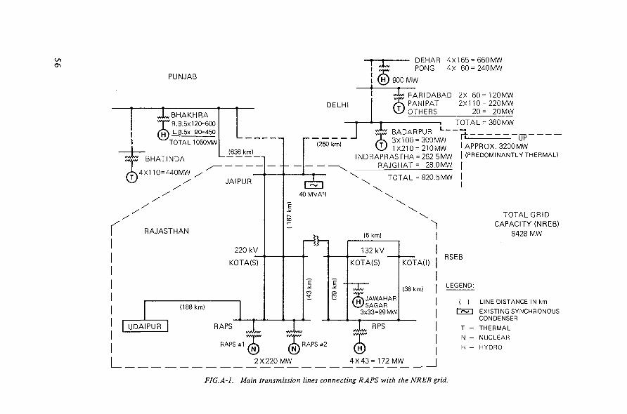
O\
PUNJAB
J^BHAKHRAvTvR.B.5x120=600/ £ \ L.B.5X 90=450
v*A*/ i
TOTAL 1050MW
BHATINDA
.4x110=440MW
(636 km)
JAIPUR
RAJASTHAN
220 kV
KOTA(S)
(188 km)
DEHAR 4X165 = 660MWPONG 4X 60 = 240MW
(H) 900 MW
DELHIFARIDABAD 2X6O=12OMWPAN I PAT 2X11O = 22OMWOTHERS 20= 20 MW
„___!V/TW
TOTAL = 360 MWBADARPUR i ,
(250 km) sK 3X100 = 300MW\L) 1X21O = 21OMW
INDRAPRASTHA = 282.5MWRAJGHAT = 28.0 MW
TOTAL = 820.5 MW
"UP"lAPPROX. 3200MWI (PREDOMINANTLY THERMAL)
40MVAR
(6 km)
132 kV
KOTA(S)
vXv
JAJAWAHAR2/SAGAR
3x33=99 MW
KOTA(I)
(38 km)
UDAIPUR
L
RAPS
RAPS #1 / f x / ^ RAPS #2
2X220 MW 4X43= 172 MW |
FIG.A-1. Main transmission lines connecting RAPS with the NREB grid.
TOTAL GRIDCAPACITY (NREB)
8428 MW
RSEB
LEGEND:
LINE DISTANCE IN kmEXISTING SYNCHRONOUSCONDENSER
T - THERMAL
N - NUCLEAR
H - HYDRO
- When a mathematical model for the system becomes available, it must betested by calculating specially selected real fault conditions. In this way, itcan be seen to what degree the mathematical model is able to replicate actualconditions. In the case of major deviations, better agreement may be achievedby changing certain specific parameters. This is also important for simulatingthe effect of neighbouring systems (interconnected systems operation withother countries, for example) if no details are available and simplified, empiricalmodels have to be used.
Appendix
CASE STUDIES
A series of case studies derived from real occurrences are reported. The first five casesare part of the operating experience accumulated at the Rajasthan Atomic Power Station.The last case presents the operating strategy adopted by a utility (the Israel ElectricCorporation) to control power generation in a limited system incorporating a relatively largeunit and with reduced provision for spinning reserve.
This Appendix may represent a useful guidance for the users of the Guidebook in specificcase problems.
A-l. LOW-PERFORMANCE GRID INCORPORATING A NUCLEAR POWER PLANT
The Rajasthan Atomic Power Station (RAPS) consists of two units of 220 MW(e) withpressurized heavy water reactors. It is situated in the state of Rajasthan and is connected tothe grid of the Rajasthan State Electricity Board (RSEB) by 220 kV transmission lines. RSEBitself forms part of the Northern Region Electricity Board (NREB) to which grids of otherstates of northern India are also connected (India is divided into five regional grids: west,east, north, south and north-east).
The installed capacities of NREB are as follows:
(210 MW(e), largest unit in Badarpur)(165 MW(e), largest unit in Dehar)(2 units of 220 MW(e), RAPS)
Figure A-l shows the main transmission lines connecting RAPS with NREB.The salient points to be noted are as follows:— RAPS is almost in the far end of the grid and separated by more than 400 km of trans-
mission lines from other large generating centres. Two hydro stations of comparativelysmaller capacities are situated near RAPS but are not able to participate very effectivelybecause their capacities are small; also, their availability is often governed by otherconsiderations, such as irrigation demand and poor hydrological conditions.
— Synchronous condensers are available at Jaipur, but there is no voltage control equipmentat Kota, RAPS and Udaipur.
ThermalHydroNuclear
Total
3938 MW(e)4050 MW(e)
440 MW(e)
8428 MW(e)
57

FIG.A-2. Grid voltage.RAPS operating on 30 April 1981RAPS not operating on 17 April 1981.
— When RAPS is operating, the voltage around RAPS can be reasonably maintained. How-ever, when RAPS is not operating, power has to be transmitted from far-away places likethe Badarpur Thermal Power Station or the Bhakra Nangal Hydro Complex. So, althoughthe voltage may be reasonably maintained in the Badarpur and Bhakra areas, the voltageat RAPS and Udaipur is governed mostly by a drop due to power flow and capacitive loadof the high-voltage transmission lines.
During peak periods when the loads are high, the transmission line drops are too sharp,causing low-voltage conditions at RAPS. On the other hand, during off-peak periods in thenight when the grid in the Rajasthan area is very lightly loaded, the voltage at RAPS risesbecause of a capacitance effect of the long transmission lines (Ferro-resonance or Ferrantieffect). The situation becomes worse because of the fact that, when RAPS is not operating,the Rajasthan grid is not able to meet the full power demand of the consumers and the gridoperators are forced to resort to load shedding, as a result of which the grid becomes morelightly loaded. A 400 MW(e) power station is being built in the vicinity of RAPS near Kota;when this station goes into operation, the voltage problem may be alleviated.
Case 1
Prolonged off-normal voltage operation
Figure A-2 shows the voltages at the RAPS 220 kV bus. One curve indicates thevoltage when the units are operating, the other curve indicates the voltage when the unitsare not operating. It can be seen that when RAPS is operating, the voltages are more or lessnormal within a band of 5 kV, varying between 230 and 225 kV. The voltage drops slightlyto 220 kV during peak hours of the morning and evening. When RAPS is not operating, thevoltage drops to 185 kV (momentarily touching 175 kV) and to 200 kV during peak hoursof the morning and evening, respectively. It can also be observed that the voltage remainsgenerally low between 8 a.m. and 7 p.m., which makes it difficult for large coolant pumpmotors to be started or run. If they are started, they trip on stall protection; if they areoperating as a prelude to start-up of the unit, they trip on overload. The overload effect isfelt more severely during reactor start-up from cold conditions because the pumps have topump up cold fluid and hence need a higher current than when the reactor is started fromhot conditions. So reactor start-up is often restricted to night hours when the voltage ishigh. Here again, if the voltage is too high, sometimes the pump motors trip on instantaneousactuation of the over-current relay.
It can be seen from the figure that when RAPS is not operating, the voltage can be ashigh as 250 kV during the night. Even when RAPS is operating, the voltage rises because ofa very high capacitive loading of the transmission lines during the night and RAPS is forcedto take high values of leading Mvar, which causes an unstable situation for the RAPS machines.
Remarks
(a) The high and low voltage conditions at the RAPS 220 kV bus when RAPS is notoperating are due to: (i) the absence of voltage control equipment, (ii) the absence ofcomparatively large thermal or hydro stations near RAPS, and (iii) the fact that the existinglarge stations are situated far away. The situation could be improved by providingvoltage control equipment, such as reactors, capacitors or synchronous condensers inthe 220 kV bus.
59

300
250
200
150 VOLTAGE (kV)
100
50
0250
200
150 |
100 MW/MVAR
50
0
5054
53
52
51
50 FREQUENCY (Hz)
49
48
47
46
FIG.A-3. Case 2: Unit outage due to voltage dip on 30 May 1980.
200
150
100
< 50
0
50
100
2334 h
\
\
24 h
2300 h
/r
2C
~t
1Ir
IOCh
1
24 h
24 h
•—•
60

150 -
100-
< 5 0 -
o-
50 -
i n n
/1V
/I
A!
10a.
MW
fT
~t /
Tl.
M ^Il l l
1MVAR
/t
1
y
10 a.m.
300
250
200
150 VOLTAGE (kV)
100
50
0
250
200
150 g
100 MW/MVAR
50
0
50
54
53
52
51
50 FREQUENCY (Hz)
49
48
47 .
4610 a.m.
FIG.A-4, Case 3: Example of successful islanding.
61

(b) Problems due to low voltage exist for the low-voltage auxiliaries because of the absenceof an on-load tap-changing facility in the unit auxiliary transformers of RAPS.
(c) The desirability of an on-load tap-changing facility on the station auxiliary supplytransformer ought to be studied on a cost/benefit basis.
Case 2
Unit outage due to voltage dip
On 30 May 1980, RAPS unit 1 was operating at 95 MW(e). At 23.34 hours, a sharpvoltage dip from 225 kV to 145 kV was recorded, as can be seen in Fig.A-3. There was afault on a 132 kV system near the Kota industrial area (KOTA-I of Fig.A-1) which was beingfed by two lines, RAPS-KOTA(I) and KOTA(S)-KOTA(I). The RAPS-KOTA(I) line trippedon distance protection, but KOTA(S)-KOTA(I) tripped only on back-up protection. Aslight delay in clearance of the fault caused a sustained voltage dip, and four main circulatingpumps in RAPS tripped on under-power relay protection, resulting in a reactor trip.
Remarks
(a) The reason for the unit outage was the persistence of low voltage for a comparativelylong time, sufficient to initiate the under-power relay. The fault could not be clearedfast enough because of the absence of distance protection relays. Fast relays shouldbe installed for quick fault identification.
(b) An islanding scheme for NPPs to be used on voltage dips for longer periods may beintroduced. The actual duration of the dip may be arrived at after taking into accountthe detection time of the relays and the clearing time of the breakers.
Case 3
Successful islanding
On 19 September 1980, RAPS unit 1 was operating at 160 MW(e). At 10.10 hours,the interconnection lines between Bhakra and the rest of the grid tripped, cutting off 850 MW(e)from the system. This resulted in a frequency drop to 46.8 H2 in the rest of the grid (seeFig.A-4), tripping most of the running units in this region.
The Jaipur-Kota lines tripped on under-frequency protection, set at 47.5 Hz. RAPSwas isolated by manually tripping the RAPS-KOTA lines. RAPS was then operated by feedingload from Udaipur radially at around 125 MW(e) until 10.32 hours when RAPS was syn-chronized with KOTA (RSEB grid). The frequency control was not good, as can be seenfrom the figure, until RSEB was synchronized with NREB at 11.07 hours. Thereafter, thefrequency improved.
Remarks
The under-frequency isolation scheme worked satisfactorily. The scheme is asfollows:
47.5 Hz inst.: KOTA-JAIPUR lines trip47.5 Hz 2min: RAPS-KOTA lines trip46.5 Hz inst.: RAPS-KOTA lines trip.
62
After islanding, the frequency control in the islanded Rajasthan grid was not proper,which resulted in frequency oscillations; these were attenuated when the Rajasthan gridwas re-connected with NREB.
Case 4
Set-back rate reduction
It is worth noting that, if the power set-back rate is too high, it may result in reducingpower too fast and to a lower value than is required. In this case, there may be a quenchingeffect, culminating in a low-pressure trip of the heat transfer system (HTS). In RAPS, theset-back rate was previously 1% of full power per second, which used to result in too fast arate of power reduction and consequent low-pressure trip of the HTS. The set-back ratewas later decreased to 0.5% of full power per second and the system stability improved.
On 5 June 1977, RAPS unit 1 was operating at 160 MW(e) when there was a reactorset-back due to problems at the station. Power generation came down to zero. The reactivepower went up from 23 to 52 Mvar. The HTS pressure dropped from 86.5 to 82 kg/cm2.There was no appreciable effect on grid voltage. The frequency dropped from 49.4 to 47.6 Hz.The power generation was raised again to 160 MW(e) in approximately 15 minutes.
The unit survived on controlled reduction of power under set-back conditions and didnot trip on low HTS pressure.
Remarks
(a) Reduction of the set-back rate from 1.0% of full power per second to 0.5% of fullpower per second helped the station to keep up operation.
(b) Reduction of the low-pressure trip setting of the HTS from 84 to 74 kg/cm2 alsohelped to avoid a low-pressure trip of the reactor.
CaseS
Voltage and frequency disturbances
Typical cases of grid disturbances in voltage and frequency are given below.
5.1. On 25 April 1976, at 12.50 hours, RAPS generation came down to house-load from100 MW(e) when the RAPS-KOTA feeders tripped on earth fault:
Frequency: 50 - 52.7 - 52.6 (10 min.), down to 50.6 - 50 HzVoltage dip: 235 - 170 - 250 - 235 kVGeneration: 100 - 12, gradually to 100 MW.The unit survived.
5.2. On 27 April 1976, the following grid fluctuations were observed:Frequency: 49.8 -48 .8 -46 .1 - 51.9 - 50.5 HzVoltage: 230 - 194 - 277 - 240 kVGeneration: 1 6 0 - 1 7 5 - 2 5 MW.The unit survived.
5.3. On 4 February 1976, the reactor tripped on high HTS pressure due to grid fluctuation:Frequency: 49.4 - 50 HzVoltage: 235 - 300 kVGeneration: 1 7 5 - 1 8 5 - 0 MW.The unit did not survive.
63
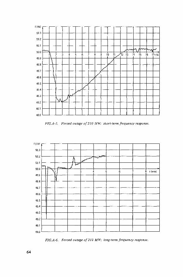
f (Hz)
50.3
50.2
50.1
50.0
49.9
49.8
49.7
49.6
49.5
49.4
49.3
49.2
49.1
49.0
\
\
\
L
J
//
1
/
0 1
AHi 13 14 15 16 17t(s)
FIG.A-5. Forced outage of 210 MW; short-term frequency response.
f (Hz)
50.3
50.2
50.1
50.0
49.9
49.8
49.7
49.6
49.5
49.4
49.3
49.2
49.1
49.0
Hs t (min)
FIG.A-6. Forced outage of 210 MW; long-term frequency response.
64
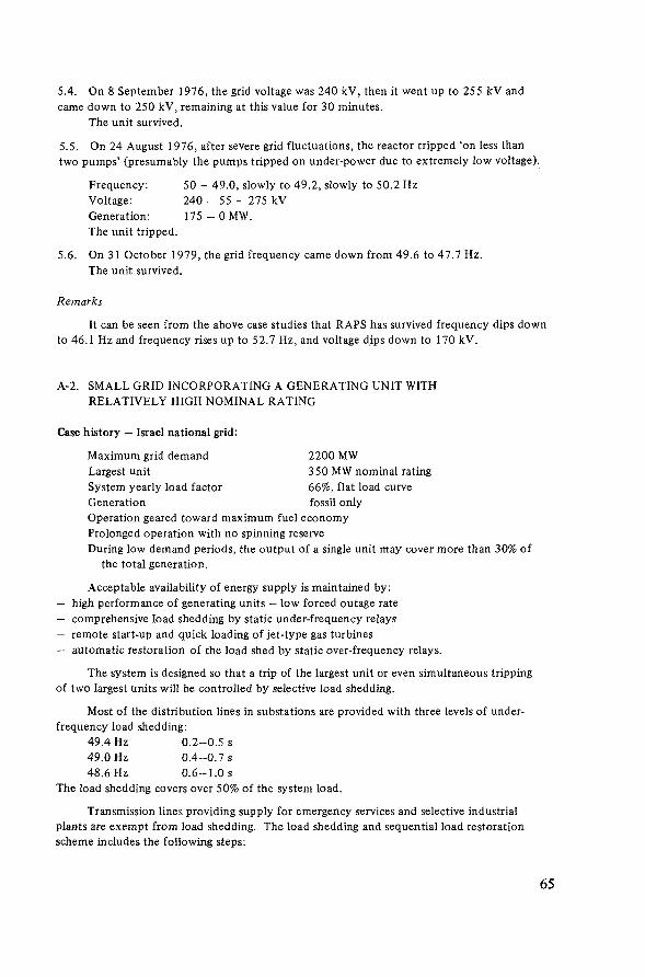
5.4. On 8 September 1976, the grid voltage was 240 kV, then it went up to 255 kV andcame down to 250 kV, remaining at this value for 30 minutes.
The unit survived.
5.5. On 24 August 1976, after severe grid fluctuations, the reactor tripped 'on less thantwo pumps' (presumably the pumps tripped on under-power due to extremely low voltage).
Frequency: 50 - 49.0, slowly to 49.2, slowly to 50.2 HzVoltage: 240 - 55 - 275 kVGeneration: 1 7 5 - 0 MW.The unit tripped.
5.6. On 31 October 1979, the grid frequency came down from 49.6 to 47.7 Hz.The unit survived.
Remarks
It can be seen from the above case studies that RAPS has survived frequency dips downto 46.1 Hz and frequency rises up to 52.7 Hz, and voltage dips down to 170 kV.
A-2. SMALL GRID INCORPORATING A GENERATING UNIT WITHRELATIVELY HIGH NOMINAL RATING
Case history — Israel national grid:
Maximum grid demand 2200 MWLargest unit 350 MW nominal ratingSystem yearly load factor 66%, flat load curveGeneration fossil onlyOperation geared toward maximum fuel economyProlonged operation with no spinning reserveDuring low demand periods, the output of a single unit may cover more than 30% of
the total generation.
Acceptable availability of energy supply is maintained by:— high performance of generating units — low forced outage rate— comprehensive load shedding by static under-frequency relays— remote start-up and quick loading of jet-type gas turbines— automatic restoration of the load shed by static over-frequency relays.
The system is designed so that a trip of the largest unit or even simultaneous trippingof two largest units will be controlled by selective load shedding.
Most of the distribution lines in substations are provided with three levels of under-frequency load shedding:
49.4 Hz 0.2-0.5 s49.0 Hz 0.4-0.7 s48.6 Hz 0.6-1.0 s
The load shedding covers over 50% of the system load.
Transmission lines providing supply for emergency services and selective industrialplants are exempt from load shedding. The load shedding and sequential load restorationscheme includes the following steps:
65

— Since the system is operated with minimum provision for spinning reserve, on a unitoutage the frequency falls and under-frequency relays located in the substations shed loadselectively at a total of 80-120% of the capacity of the lost unit
— In 3—10 seconds, the frequency recovers to near normal after an initial frequency dropdepending upon system inertia
— In approximately 5 minutes, remotely operated jet-type gas turbines are started and loaded,and the frequency is maintained slightly higher, at about 50.1 Hz, to enable re-connectionof load without deterioration of frequency
— Loads which had been shed earlier are restored sequentially in steps by over-frequencyrelays
— In 10—15 minutes, the system normally recovers and the gas turbines which are no longerneeded are shut down.
The system frequency is monitored at intervals of 0.1 s by a digital device with memoryand a 'post-trip' retrieval facility. The print-out typically includes the frequencies duringtwo minutes before the occurrence and during eight minutes after the occurrence.
Case 6
Tripping of 18% of generation
System load before unit trip 1142 MWSystem frequency before unit trip 50 Hz ± 0.06 HzUnit tripped (225 MW capacity), operating at 210 MWSpinning reserve 170 MWLoad shed 180 MWFrequency drop to 49.2 HzFrequency restoration after load shedding in 11s
The frequency behaviour is shown in Figs A-5 and A-6.The load was completely restored after 10 minutes.
66

LIST OF PARTICIPANTS
The following meetings were held in Vienna with the purpose of assisting theIAEA in the preparation of this Guidebook:
Advisory Group MeetingConsultants' MeetingConsultants' Meeting
6-10 October 19802 - 5 March 19819-20 November 1981
The participants of these meetings were:
Aleite, W.
Bayer, W.
Ghosh, G.
Kraftwerk Union,P.O. Box 3220,D-8520 Erlangen,Federal Republic of Germany
Siemens AG,P.O. Box 3240,D-8520 Erlangen,Federal Republic of Germany
Rajasthan Atomic Power Station,Anushakti P.O.,Rajasthan,India
Kiirten, H.
Lisboa da Cunha, M.
Kraftwerk Union,P.O. Box 3220,D-8520 Erlangen,Federal Republic of Germany
FURNAS Centrais Electricas S.A.,Rua Real Grandeza 219,Rio de Janeiro,Brazil
Nelken, M.
Ray, R.N.
Israel Electric Corporation Ltd.,P.O. Box 10,Haifa,Israel
Reactor Control Division,Bhabha Atomic Research Centre,Trombay, Bombay 4000085,India
67

Sahin, S. Turkish Electricity Authority,Hanimeli Sok.9,Ankara,Turkey
Weaner, R. Department of Energy,2000 M Street N.W.,Washington, DC,United States of America
Mr. F. Calori of the IAEA Division of Nuclear Power was responsible forco-ordinating this work.
68

HOW TO ORDER IAEA PUBLICATIONS
An exclusive sales agent for IAEA publications, to whom all ordersand inquiries should be addressed, has been appointedin the following country:
UNITED STATES OF AMERICA UNIPUB, P.O. Box 433, Murray Hill Station, New York, NY 10016
In the following countries IAEA publications may be purchased from thesales agents or booksellers listed or through yourmajor local booksellers. Payment can be made in localcurrency or with UNESCO coupons.
ARGENTINA
AUSTRALIABELGIUM
CZECHOSLOVAKIA
FRANCE
HUNGARY
INDIA
ISRAEL
ITALY
JAPANNETHERLANDS
PAKISTANPOLAND
ROMANIASOUTH AFRICA
SPAIN
SWEDEN
UNITED KINGDOM
U.S.S.R.YUGOSLAVIA
Comisión Nacional de Energía Atómica, Avenida'del Libertador 8250,RA-1429 Buenos AiresHunter Publications, 58 A Gipps Street, Collingwood, Victoria 3066Service Courrier UNESCO, 202, Avenue du Roi, B-1060 BrusselsS.N.T.L.,Spálená51, CS-113 02 Prague 1Alfa, Publishers, Hurbanovo namestie 6, CS-893 31 BratislavaOffice International de Documentation et Librairie, 48, rue Gay-Lussac,F-75240 Paris Cedex 05Kultura, Hungarian Foreign Trading CompanyP.O. Box 149, H-1389 Budapest 62Oxford Book and Stationery Co., 17, Park Street, Calcutta-700 016Oxford Book and Stationery Co., Scindia House, New Delhi-110 001Heiliger and Co., Ltd., Scientific and Medical Books, 3, Nathan StraussStreet, Jerusalem 94227Librería Scientifica, Dott. Lucio de Biasio "aeiou".Via Meravigli 16, 1-20123 MilanMaruzen Company, Ltd., P.O. Box 5050, 100-31 Tokyo InternationalMartinus Nijhoff B.V., Booksellers, Lange Voorhout 9-11, P.O. Box 269,NL-2501 The HagueMirza Book Agency, 65, Shahrah Quaid-e-Azam, P.O. Box 729, Lahore 3Ars Polona-Ruch, Céntrala Handlu Zagranicznego,Krakowskie Przedmiescie 7, PL-00-068 Warsawllexim, P.O. Box 136-137, BucarestVan Schaik's Bookstore (Pty) Ltd., Libri Building, Church Street,P.O. Box 724, Pretoria 0001Diaz de Santos, Lagasca 95, Madrid-6Diaz cie Santos, Balmes 417, Barcelona-6AB C.E. Fritzes Kungl. Hovbokhandel, Fredsgatan 2, P.O. Box 16356,S-103 27 StockholmHer Majesty's Stationery Office, Agency Section PDIB, P.O.Box 569,London SE1 9NH
Mezhdunarodnaya Kniga, Smolenskaya-Sennaya 32-34, Moscow G-200Jugoslovenska Knjiga, Terazije 27, P.O. Box 36, YU-11001 Belgrade
Orders from countries where sales agents have not yet been appointed andrequests for information should be addressed directly to:
Division of PublicationsInternational Atomic Energy AgencyWagramerstrasse 5, P.O. Box 100, A-1400 Vienna, Austria

INTERNATIONAL SUBJECT GROUP: VATOMIC ENERGY AGENCY Reactors and Nuclear Power/Reactor TechnologyVIENNA, 1983 PRICE: Austrian Schillings 180,-
Related Documents