ử 14th Edition Technical Drawing with Engineering Graphics

Welcome message from author
This document is posted to help you gain knowledge. Please leave a comment to let me know what you think about it! Share it to your friends and learn new things together.
Transcript
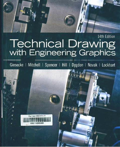
ử14th Edition
Technical Drawingwith Engineering G raphics

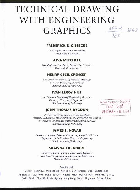
TECHNICAL DRAWING WITH ENGINEERING
GRAPHICS jSU--I t c
FREDERICK E. CIESECKELate Professor Emeritus o f Drawing
Texas A&M University
ALVA MITCHELLLate Professor Emeritus o f Engineering Drawing
Texas A & M University
HENRY CECIL SPENCERLate Professor Emeritus o f Technical Drawing:
Formerly Director o f Department Illinois Institute o f Technology
IVAN LEROY HILLLate Professor Emeritus o f Engineering Graphics:
Formerly Chairman o f Department Illinois Institute o f Technology
JOHN THOMAS DYCDONProfessor Emeritus o f Engineering Graphics;
Formerly Chairman o f the Department, and Director o f the Division o f Academic Services and Office o f Educational Services
Illinois Institute o f Technology
JAMES E. NOVAKSenior Lecturer and Director, Engineering Graphics Division
Department o f Civil and Architectural Engineering Illinois Institute o f Technology
SHAWNA LOCKHARTFormerly Adjunct Professor, Engineering Graphics
Department o f Industrial and Mechanical Engineering Montana State University
OẠI HOC KĨ cậ ty i6 ‘iiịpỊ
THƯ ỊP H Õ ^ i í ì 1
Prentíce Hall
Boston Columbus Indianapolis New York San Francisco Upper Saddle River Amsterdam Cape Town Dubai London Madrid Milan Munich Paris Montreal Toronto
Delhi Mexico City Sào Paulo Sydney Hong Kong Seoul Singapore Taipei Tokyo
Editorial Director: Vernon R. AmhonyAcquisitions Editor: Sara EllenEditorial Assistant; Doug GreiveDirector of Marketing: David GesellSenior Marketing Manager: Harper ColesSenior Marketing Coordinator: Alicia WozniakMarketing Assistant: Les RobensProject Manager: Maren L. MillerSenior Managing Editor: JoEllen GohrAssociate Managing Editor: Alexandrina Benedicto WolfSenior Operations Supervisor: Pat Tonneman
Operations Specialist: Deidra Skahill Art Director: Jayne Come Cover Designer; Bruce Kenselaar Cover Image; Potolia © Zbynek Jirousek AV Project Manager: Janet Ponisch Full-Service Project Management; Lisa Garboski,
bookworks publishing services Composition: S4Carlisle Publishing Services Printer/Binder: Courier/Kendaltville Cover Printer: Lehigh-Phoenix Color/Hagerslown Text Font: Times 10/12
Credits and acknowledgments borrowed from other sources and reproduced, with permission, in this textbook appear on th appropriate page within the text. Unless otherwise stated, all artwork has been provided by the authors.
SolidWorks* is a registered ưademark of DS SolidWorks Corp.
Certain images and materials contained in this text were reproduced with permission of Autodesk. Inc. © 2010. All rights reserved. Autodesk. AutoCAD, DWG. and the DWG logo are registered trademarks of Autodesk. Inc., in the U.S.A. and certain other counưies.
Copyright 6 2012, 2009, 2003,2000, 1997 Pearson Education, Inc., publishing as Prentice Hall. One Lake Street, Upper Saddle River, New Jersey, 07458. All rights reserved. Manufactured in the United Stales of America. This publication is protected by Copyright, and permission should be obtained from the publisher prior to any prohibited reproduction, storage in a retrieval system, or transmission in any form or by any means, electronic, mechanical, photocopying, recording, or likewise. To obtain permission(s) to use material from dlls work, please submit a written request to Pearson Education. Inc.. Permissions Department, One Lake Street, Upper Saddle River, New Jersey, 07458.
Many of the designations by manufacturers and seller to distinguish their products are claimed as trademarks. Where those designations appear in this book, and the publisher was aware of a trademark claim, the designations have been printed in initial caps or all caps.
Library of Congre&s Cataloging-in-Publication DataTechnical drawing with engineering graphics / Frederick E. Giesecke . . . [et al.]. — 14th ed.
p. cm.ISBN 0-13-509049-01. Mechanical drawing. 1. Giesecke, Frederick E. (Frederick Ernest),
1869-1953.T353.T28 2012604.2—dc22 2010044110
Prentice Hatlis an imprint of
PEARSON10 9 8 7 6 5 4 3 2
www.pearsonhighered.comISBN 10: ISBN 13:
0-13-509049-0978-0-13-509049-7
F O U R T E E N T H E D I T I O N
TECHNICAL DRAWING WITH ENGINEERING
GRAPHICS— ABOUT THIS BOOK ---------
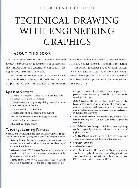
The fourteenth edition of Giesecke's Technical Drawing with Engineering Graphics is a comprehensive introduction and detailed reference for creating 2D documentation drawings.
Expanding on its reputation as a trusted reference for drawing technique, this edition continues to provide excellent integration of illustrations
Updated Content• Updated to conform to ANSI Y 14.5-2009 standard.s
for dimen.sioning and tolerancing• Updated tolerance chapter explaining datum frames in
terms of degrees of freedom• New and updated illustrations• Updated chapter on geometric construction• Inclusion of information on drawing set screws• Updated software examples• Thorough accuracy check
Teaching/Learning FeaturesVisually oriented students and busy professionals will quickly locate content by navigating these consistent chapter features.
• Splash Spread An attention-getting chapter opener interests readers and provides a context for the chapter content that follows.
• References and Web Links Applicable references to standards and links to a companion website are at the beginning of each chapter.
• Foundations Section An introductory section, set off by a topic heading lab at the top of the page for easy
within the text and consistent navigational features that make it easier to refer to important information.
This edition illustrates the application of technical drawing skills to real-world work practice, integrates drawing skills with CAD use in a variety of disciplines, and is updated with the most current ASME standards.
navigation, covers the drawing topic’s usage and importance, visualization tips, and theory related to the drawing techniques.
• Detail Section This is the “brass tacks” part of the book, where detailed explanations of drawing techniques. variations, and examples are organized into quick-read sections, each numbered for quick reference in the detailed Contents.
• CAD at Work Section This breakout page includes lips related to using the 2D or .^D CAD model to generate drawings.
• Portfolio Section Examples of finished drawings wrap up the chapter by showing real-world application of topics presented.
• Key Words Set in bold italics on first reference, key words are summarized at the end of the chapter.
• Chapter Summary• Review Questions• Chapter Exercises The excellent Giesecke problem
sets feature updated exercises, including plastic and sheet metal parts, updated assembly drawings from CAD models, and sketching problems.

USING THIS BOOKThe following features were designed to provide easy navigation and quick reference for students and professionals who look to Giesecke both as a helpfully organized teaching text and a lasting reference for technical drawing information.
Chapters are keyed in alternating colors to help you locate frequently referenced content by memory,
CHAPTER OPENER SECTIONS
A bold vertical color band and oversized number on the first page of each chapter help you flip to find topics quickly.
Topics that you can expect to learn about in this chapter are listed here.
C H A P T E R O N
A large illustration and an interesting overview give you a real-woiid context for what this chapter is about.
/
THE W O^DW IDE GRAPHig/LANGUAGE
DESIGN
OBJECTIVES
Dncrlbe the mlc of dnwtnp In the detlfn proceu. Coemesl concurrent venm tredittoruJ dertgn procetm UM Itve profeuloru thit cue icchnKeJ drrwinfi
1 -ItiS On-m Men Wa
Drawing standards that apply to this chapter are shown here.
i i'1̂
m Wf-
ConceptujI Sketchet ỉxpíohng mtỵrr drùgn ophonj thmugh qtwcJi UteTcher 0 one method that lunof. recen one of the fop to oteonhwmnmpAmenron product des^ hrmt hy BcnktettWeeli moponne, met rocreofr b pcoducn ond Ujcmiu bnmdi (Courteiy at Lunar Oeugn)
ot the Unnuaxe they kpeak, propte all meeting pfoieci budgMs ai graphic communKallon
AccompUahlngMleas, trorniheslmpteniolhemoci trade, enjpneen, archlicctt, drafters, designers, ma laborale, requires teamteork. A new product, machine, facturecs, and Icchniclaju learn the tools id techn injcture, or system may exist In tne mlndot theengi' drawing. They team specific methods to represent Id eer or designer, but betore It can become a reality, the designs, and spcclflcations In a consistcni way that ( lea must be comiminKated to many cUffertni people ers can understand Being anetfecllve graphic comt
A reminder to check the companion website is shown here.
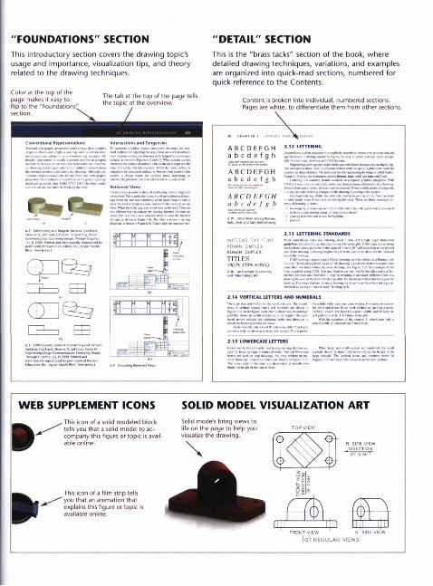
"FOUNDATIONS" SECTIONThis introductory section covers the drawing topic's usage and importance, visualization tips, and theory related to the drawing techniques.
Color at the top of the page makes it easy to flip to the "Foundations" section.
The tab at the top of the page tells the topic of the overview.
Conventional Repreỉcntaliont Interjections and Tangencies
SurtKn (Lochhan. STiawna D. ỉolvncvi, Cindy M,
1 7
"DETAIL" SECTIONThis Is the "brass tacks" section of the book, where detailed drawing techniques, variations, and examples are organized into quick-read sections, numbered for quick reference to the Contents.
Content Is broken into individual, numbered sections. Pages are white, to differentiate them from other sections.
WEB SUPPLEMENT ICONS- This icon of a solid modeled block
tells you that a solid model to accompany this figure or topic is available online.
This icon of a film strip tells you that an animation that explains this figure or topic is available online.
SOLID MODEL VISUALIZATION ARTSolid models bring views to life on the page to help you visualize the drawing.
FRONT VIEW 9 SIDE VIEW(a) R E G U L A R V IEW S
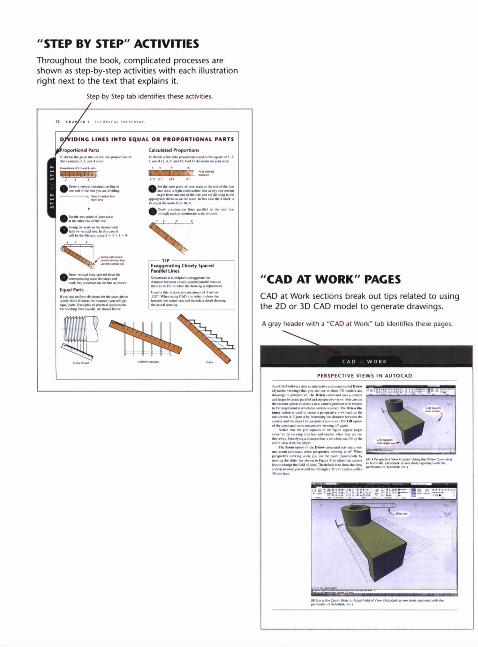
"STEP BY STEP" ACTIVITIESThroughout the book, complicated processes are shown as step-by-step activities with each illustration right next to the text that explains it.
Step by Step tab identifies these activities.
"CAD AT WORK" PACESCAD at Work sections break out tips related to using the 2D or 3D CAD model to generate drawings.A gray header with a "CAD at Work" tab identifies these pages.
PERSPECTIVE VIEWS IN AUTOCAD
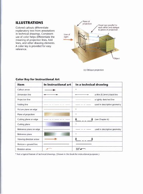
ILLUSTRATIONSColored callouts differentiate explanatory text from annotations in technical drawings. Consistent use of color helps differentiate the meaning of projection lines, fold lines, and other drawing elements. A color key is provided for easy reference.
(c) Oblique projection
Color Key for Instructional Art
Item In instructional art In a technical draw ingCallout arrow
Dimension line a thin (0.3mm) black line
Projection line a lightly sketched line
Folding line used in descriptive geometry
Picture plane on edge
Plane of projection
Cutting plane on edge (see Chapter 6)
Cutting plane
Reference plane on edge used in descriptive geometry
Reference plane
Viewing direction arrow
Horizon + ground line
Rotation arrow 30°>* Not a typical feature of technical drawings. (Shown in this book for instructional purposes.)
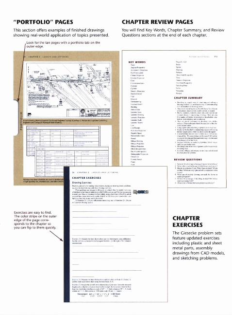
"PORTFOLIO" PACESThis section offers examples of finished drawings showing real-world application of topics presented.
CHAPTER REVIEW PAGESYou will find Key Words, Chapter Summary, and Review Questions sections at the end of each chapter.
Related Documents