European Data Sheet 1 © The information contained within these data sheets remain the property of RMD Kwikform and is not to be altered or reproduced without permission. RMD Kwikform reserves the right to change any specification without giving prior notice. Date: 17/01/2018 Issue : PS01 PARASLIM MODULAR CANTILEVER FRAME FALSEWORK Technical Data Sheets Metric Specification European Technical Office Brickyard Road, Aldridge, Walsall WS9 8BW, UK. Telephone: +44 1922 743743 Email: [email protected] Website: www.rmdkwikform.com

Welcome message from author
This document is posted to help you gain knowledge. Please leave a comment to let me know what you think about it! Share it to your friends and learn new things together.
Transcript

European Data Sheet 1 © The information contained within these data sheets remain the property of RMD Kwikform and is not to be altered or reproduced without permission. RMD Kwikform reserves the right to change any specification without giving prior notice.
Date: 17/01/2018 Issue : PS01
PARASLIM MODULAR CANTILEVER FRAME FALSEWORK
Technical Data Sheets Metric Specification
European Technical Office Brickyard Road, Aldridge, Walsall WS9 8BW, UK. Telephone: +44 1922 743743 Email: [email protected] Website: www.rmdkwikform.com

European Data Sheet 2 © The information contained within these data sheets remain the property of RMD Kwikform and is not to be altered or reproduced without permission. RMD Kwikform reserves the right to change any specification without giving prior notice.
Date: 17/01/2018 Issue : PS01
PARASLIM MODULAR CANTILEVER FRAME FALSEWORK
Contents
Ref Description Page
Contents Contents 2-4 Introduction 5
1.0 Components and Load Capacities SSX13600 Superslim Soldier 3600mm 6 SSX12700 Superslim Soldier 2700mm 6 SSX11800 Superslim Soldier 1800mm 6 SSX10900 Superslim Soldier 900mm 6 SSX10720 Superslim Soldier 720mm 6 SSX10540 Superslim Soldier 540mm 6 SSX10360 Superslim Soldier 360mm 6 SSU10035 Superslim Soldier 360mm OE 6 SSX10090 Superslim Soldier 90mm 6 SSX10040 Superslim End Plate 10mm 6 AFX11200 Alform Beam 1200mm 9 AFX11500 Alform Beam 1500mm 9 AFX11800 Alform Beam 1800mm 9 AFX12100 Alform Beam 2100mm 9 AFX12400 Alform Beam 2400mm 9 AFX12700 Alform Beam 2700mm 9 AFX13600 Alform Beam 3600mm 9 AFX14200 Alform Beam 4200mm 9 AFX14800 Alform Beam 4800mm 9 AFX15400 Alform Beam 5400mm 9 AFX16000 Alform Beam 6000mm 9 AFX16600 Alform Beam 6600mm 9 AFX17200 Alform Beam 7200mm 9 AFX20015 Alform Superslim Clamp 10 ALX10001 Universal Clamp 10 PSX10032 Paraslim Undercarriage Assembly 11 PSX10007 Paraslim Turnbuckle Forkend 11 PSX10008 Paraslim Tilt Plate 11 & 12 PSX10009 Paraslim Tube Inner 11 & 13 PSX10010 Paraslim Tube Outer 11 & 13 SSX10046 Superslim Pin & R-clip 11 BNU20015 M20x100 Bolt gr8.8 BZP 11 BNU20002 M20 Nyloc nut gr8.8 BZP 11 PSX10035 Paraslim Tilt Plate Bearing Pad 11 & 12 BNX10007 M10x35 Set Pin gr8.8 BZP Csk 11 MNX10076 M10 Nyloc Nut 11 SSU10029 Rocking Head Washer M10 11 SSU10016 Superslim Turnbuckle 914-1160 13 SSU10024 Slimshor Tube Clamp 14 SSU10003 Superslim 90 Degree Corner 14 SSX10037 Superslim Pivot Corner 20mm 15
CONTENTS

European Data Sheet 3 © The information contained within these data sheets remain the property of RMD Kwikform and is not to be altered or reproduced without permission. RMD Kwikform reserves the right to change any specification without giving prior notice.
Date: 17/01/2018 Issue : PS01
PARASLIM MODULAR CANTILEVER FRAME FALSEWORK
Contents…...continued
Ref Description Page BNU16007 M16x40 Set Pin - gr8.8 BZP 16 BNU16013 M16x110 Bolt - gr8.8 BZP 16 BNU16008 M16x40 Set Pin - gr8.8 BZP Csk 16 BNU16001 M16 Nut - gr8 BZP 16 BNU20001 M20 Nut - gr8 BZP 16 BNU24001 M24 Nut - gr8 BZP 16 & 27 BNX20030 M20x90 Bolt - gr8.8 BZP 16 BNU24004 M24x60 Bolt gr8.8 BZP 16 BNU24002 M24 Round Washer BZP 16 SSX10046 Superslim Pin & R-clip 16 & 23 BTX10001 Knock On Wing Nut 17 BTU10015 Paraslim wing Nut ’O’ Ring 17 PSU20001 Paraslim Safetie Bearing 18 BTU10002 Flexible Hose 25/31 30m lg 18 PSU20002 Paraslim Safetie Nut 18 PSX10003 Paraslim Bracket 35 deg Cast 19 PSX10039 Paraslim Bracket 50 deg Cast 19 BTX30015 Bar Tie per m 15mm 20 PSU20003 Paraslim Safetie Stop 20 PSU20006 Paraslim Plastic Tube 51dia/m 20 FAU10141 Foam Sleeve 22/60 dia per m 21 PSU20004 Paraslim Safetie Spanner 21 PSU20009 Paraslim Restraint Hook 22 AGU20013 Quicklink 10mm 23 AGU20015 Galvanised Chain 8mm x 3050mm 23 AGU20016 10mm Turnbuckle 222-320mm 23 PSX10014 Webtie Edge Protector 23 SAX12550 Ultraguard Barrier 2550mm 24 SAX13150 Ultraguard Barrier 3150mm 24 SAX11200 Ultraguard Handrail Post 1200mm 24 SAX10005 Ultraguard Aluminium Beam Bracket 24 SAX10012 Ultraguard Soldier Socket 24 ASX10067 Twin Pronged Table C-Hook 25 PSX10001 Paraslim Weld Stud & Ferrule M24x50 26 PSX10041 M24x475mm long All Thread Rod gr8.8 27 BTX10027 RMDK Hydraulic Test Kit 27 BNX20019 75x75x6x26 Plate Washer 27 PSX10042 M24x48 long High Yield Coupler 27 PSX10040 Open Sided Test Stool 27 FAU10045 Cast-in Socket Anchor M24x200 28
2.0 Applications 29-34
3.0 Design Data 35-38
4.0 Appendix ‘A’ - Paraslim Access Platform 39-43 SSU10035 Superslim Soldier 360mm OE - Post 2002 40 SSX10048 Superslim Safety Latch 41 SSX10061 Superslim O/E M24 Cone Bobbin (SSX10061) 42 RCX10009 Rapidclimb 45kN Cone (RCX10009) 42
CONTENTS
European Data Sheet 4 © The information contained within these data sheets remain the property of RMD Kwikform and is not to be altered or reproduced without permission. RMD Kwikform reserves the right to change any specification without giving prior notice.
Date: 17/01/2018 Issue : PS01
PARASLIM MODULAR CANTILEVER FRAME FALSEWORK
Contents…...continued
Ref Description Page HTX24280 Anchor Screw M24 x 280 42 HTX24200 Anchor Screw M24 x 200 42 HTX24140 Anchor Screw M24 x 140 42 HTX10015 Extractor Key Head M24 42 HTX10013 Extractor Key Arm 42 AGX10028 Ascent Anchor Plate 43 RCX10020 Rapidclimb 45kN Cone Retainer 43 RCX10021 Rapidclimb Cone Retainer Key 43
CONTENTS
European Data Sheet 5 © The information contained within these data sheets remain the property of RMD Kwikform and is not to be altered or reproduced without permission. RMD Kwikform reserves the right to change any specification without giving prior notice.
Date: 17/01/2018 Issue : PS01
PARASLIM MODULAR CANTILEVER FRAME FALSEWORK
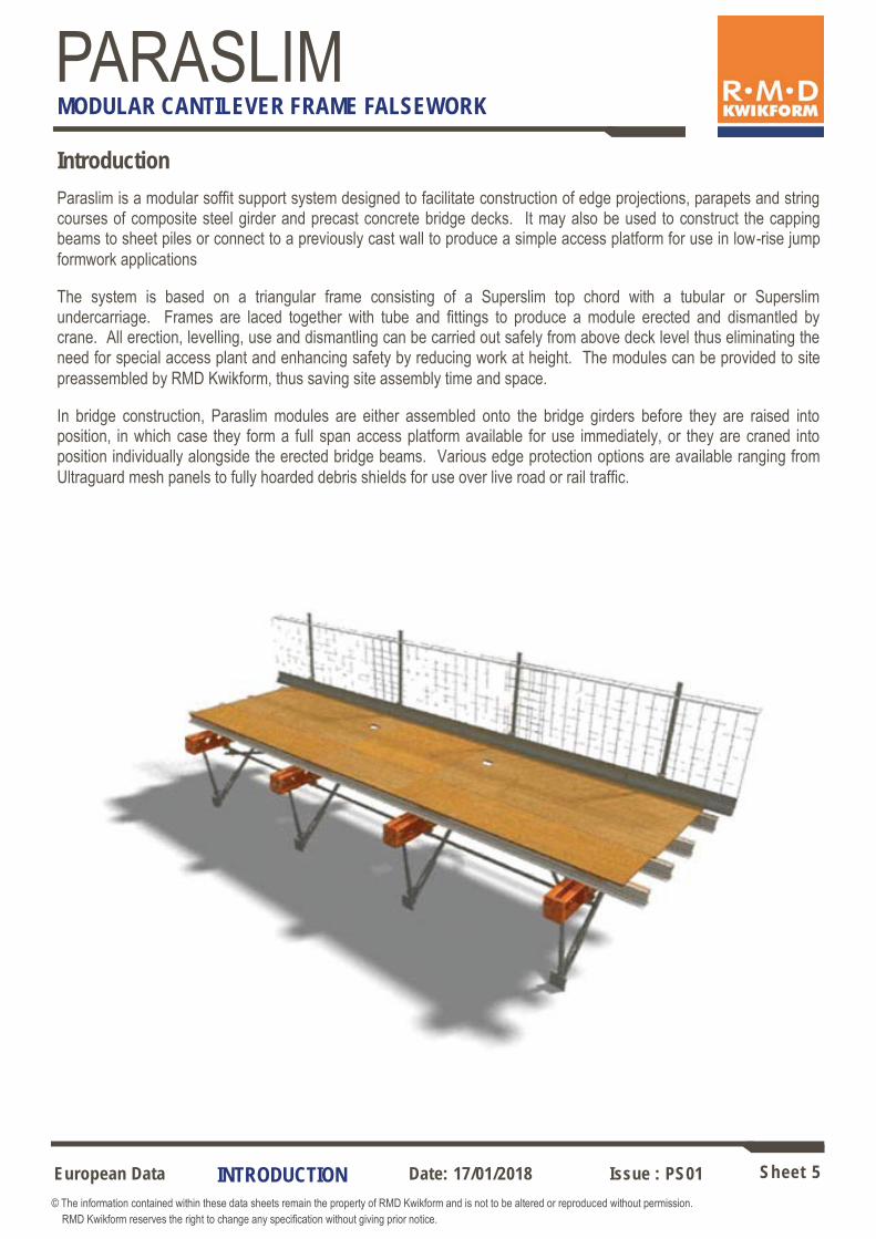
Introduction Paraslim is a modular soffit support system designed to facilitate construction of edge projections, parapets and string courses of composite steel girder and precast concrete bridge decks. It may also be used to construct the capping beams to sheet piles or connect to a previously cast wall to produce a simple access platform for use in low-rise jump formwork applications
The system is based on a triangular frame consisting of a Superslim top chord with a tubular or Superslim undercarriage. Frames are laced together with tube and fittings to produce a module erected and dismantled by crane. All erection, levelling, use and dismantling can be carried out safely from above deck level thus eliminating the need for special access plant and enhancing safety by reducing work at height. The modules can be provided to site preassembled by RMD Kwikform, thus saving site assembly time and space.
In bridge construction, Paraslim modules are either assembled onto the bridge girders before they are raised into position, in which case they form a full span access platform available for use immediately, or they are craned into position individually alongside the erected bridge beams. Various edge protection options are available ranging from Ultraguard mesh panels to fully hoarded debris shields for use over live road or rail traffic.
INTRODUCTION

European Data Sheet 6 © The information contained within these data sheets remain the property of RMD Kwikform and is not to be altered or reproduced without permission. RMD Kwikform reserves the right to change any specification without giving prior notice.
Date: 17/01/2018 Issue : PS01
PARASLIM MODULAR CANTILEVER FRAME FALSEWORK
COMPONENTS
Superslim Soldiers
Used as the primary beam in Paraslim applications
Area: Gross Area: Nett I xx I yy r xx r yy Z xx Z yy El xx El yy GAxx M max x M max y Max Joint Moment (4 M16 bolts) Max Joint Moment (6 M16 bolts) Max Joint Moment (stiffeners see 1.2.1. sheet 16) Max Joint Tension (4 M16 bolts) Max Joint Tension (6 M16 bolts) Max Joint Tension (4 M16 bolts and stiffeners) Mean compressive yield stress Mean Self weight for Analysis
26.06 cm2 19.64 cm2 1916 cm4 658 cm4 9.69 cm 5.70 cm 161 cm3 61 cm3 4020 kNm2 300 kNm2 17350 kN 40 kNm 6.24 kNm 12 kNm 18 kNm 20 kNm 100 kN 140 kN 150 kN 370 N/mm2 0.235 kN/m run*
* Self weight varies depending on makeup / length - see below
Y
X X
Y
Direction A Direction B Direction C
0.177 m2/m 0.130 m2/m 0.286 m2/m
Effective area (Ae) for wind calculation purposes
A
B
C
Code Description Weight SSX13600 Superslim Soldier 3600mm 72.2 kg SSX12700 Superslim Soldier 2700mm 55.4 kg SSX11800 Superslim Soldier 1800mm 38.8 kg SSX10900 Superslim Soldier 900mm 22.0 kg SSX10720 Superslim Soldier 720mm 18.7 kg SSX10540 Superslim Soldier 540mm 15.2 kg SSX10360 Superslim Soldier 360mm 12.0 kg SSU10035 Superslim Soldier 360mm OE 11.7 kg SSX10090 Superslim Soldier 90mm 7.3 kg SSX10040 Superslim End Plate 10mm 2.9 kg

European Data Sheet 7 © The information contained within these data sheets remain the property of RMD Kwikform and is not to be altered or reproduced without permission. RMD Kwikform reserves the right to change any specification without giving prior notice.
Date: 17/01/2018 Issue : PS01
PARASLIM MODULAR CANTILEVER FRAME FALSEWORK
60mm
Punchings and Geometry
100mm dia porthole max bearing in hole pair 65kN
Detail on End Plate 10mm thick - Post 1994 version
Typical Section
Detail on End Plate of 360mm Open End Soldier Pre 2002
Detail on End Plate of 360mm Open End Soldier Post 2002
Note The arrangement of holes in the end plates of hire fleet soldiers vary.
Detail on End Plate 8mm thick Pre 1994 version
120mm
180mm
180mm
90mm
180mm
180mm
24
45mm
65mm
225mm 225mm
100 Dia 180mm
106 176mm
137mm
45mm
80mm
125
27 Dia.
18 Dia.
65mm
225mm
106 176mm
125 27 Dia.
18 Dia.
R=13.5
Channels 3.2mm or 3.5mm thick
M20 x 90 Bolt/Nut gr 8.8 (BNX20030+BNU20001) = 45kN
M20 x 100 Bolt/Nut gr 8.8 (BNU20015+BNU20001) = 50kN
Superslim 19mm Pin & R-clip
(SSX10046) = 50kN
42mm
126mm
70
21mm dia max bearing in hole pair when used with:-
COMPONENTS

European Data Sheet 8 © The information contained within these data sheets remain the property of RMD Kwikform and is not to be altered or reproduced without permission. RMD Kwikform reserves the right to change any specification without giving prior notice.
Date: 17/01/2018 Issue : PS01
PARASLIM MODULAR CANTILEVER FRAME FALSEWORK
Bolted Joints
Allowable Bending Moment = 20kNm
150kN
4 No. S/Slim Joint Stiffeners Galv (SSU10010)with 4 No. M16 x 110 Bolts gr8.8 and nuts (BNU16013 & BNU16001)
Allowable Bending Moment = 18kNm
140kN
6 No. M16 x 40 Set Pin gr8.8 with nut (BNU16007 & BNU16001)
Allowable Bending Moment = 12kNm
4 No. M16 x 40 Set Pin gr8.8 with nut (BNU16007 & BNU16001)
100kN
150kN
140kN
100kN
Using M16 x 40 gr 8.8 Set Pins & nut BNU16007 & BNU16001
Allowable Bending Moment = 9kNm
90kN
2 No. M16 x 40 Set Pin gr8.8 with nut (BNU16007 & BNU16001)
90kN
Combined Stresses - Tension & Bending must satisfy:-
Actual Tensile Load Actual Bending Moment + ≤1
Using Joint Stiffeners with M16x110 gr 8.8 bolts & nuts
Allowable Tensile Load Allowable Bending Moment
COMPONENTS

European Data Sheet 9 © The information contained within these data sheets remain the property of RMD Kwikform and is not to be altered or reproduced without permission. RMD Kwikform reserves the right to change any specification without giving prior notice.
Date: 17/01/2018 Issue : PS01
PARASLIM MODULAR CANTILEVER FRAME FALSEWORK
COMPONENTS
Alform Beams Used as a secondary beam in Paraslim applications.
Code Description Weight AFX11200 Alform Beam 1200mm 6.8 kg AFX11500 Alform Beam 1500mm 8.5 kg AFX11800 Alform Beam 1800mm 10.1 kg AFX12100 Alform Beam 2100mm 11.3 kg AFX12400 Alform Beam 2400mm 13.5 kg AFX12700 Alform Beam 2700mm 15.2 kg AFX13600 Alform Beam 3600mm 20.3 kg AFX14200 Alform Beam 4200mm 23.7 kg AFX14800 Alform Beam 4800mm 27.1 kg AFX15400 Alform Beam 5400mm 30.5 kg AFX16000 Alform Beam 6000mm 33.9 kg AFX16600 Alform Beam 6600mm 37.3 kg AFX17200 Alform Beam 7200mm 40.7 kg
Alform Beam Properties
Gross Area 17.6cm2 Second Moment of area I xx 558cm4 Flexural Rigidity EI 384kNm2 Shear Rigidity GA xx 18489kN Maximum Bending Moment xx 10kNm Max Reaction (Intermediate) 75mm bearing 55kN Max Reaction (End) 44mm bearing 40kN Self Weight (with timber insert) 5.66kg/m
150
90

European Data Sheet 10 © The information contained within these data sheets remain the property of RMD Kwikform and is not to be altered or reproduced without permission. RMD Kwikform reserves the right to change any specification without giving prior notice.
Date: 17/01/2018 Issue : PS01
PARASLIM MODULAR CANTILEVER FRAME FALSEWORK
COMPONENTS
Used to connect Alform secondary beams to Soldiers.
Alform Superslim Clamp (AFX20015) weight 0.16kg
Tighten wing nut hand tight plus 1/4 turn
AWL Slip along Soldier = 1.0kN
AWL Slip along Alform = 0.75kN
Clamp Assembly - Superslim (Sally Clamp)
Universal Clamp (ALX10001) weight 0.75kg
A secure serrated clamp used with all falsework systems in crane handled applications. Connects Albeam, Alform, Alsec, Superslim Soldiers, GTX150 and T200 composite timber beams in any combination. Tighten the unit by tapping the wings of the nut with a hammer.
Secondary to Primary Connection
AWL Tension = 2.5kN
AWL Slip = 0.35kN
Alsec Universal Clamp (ALX10001) Stagger Alternate Clamps

European Data Sheet 11 © The information contained within these data sheets remain the property of RMD Kwikform and is not to be altered or reproduced without permission. RMD Kwikform reserves the right to change any specification without giving prior notice.
Date: 17/01/2018 Issue : PS01
PARASLIM MODULAR CANTILEVER FRAME FALSEWORK
COMPONENTS
An assembly of fully galvanised parts used together with a Superslim Turnbuckle and a Superslim Soldier to form a Paraslim Frame.
Incorporates the following features: 1. Paraslim Tilt Plate with integral 6mm thick, polypropylene girder
paintwork protection pad.2. Telescopic Paraslim Inner and Outer Tubes fixed to length with a pin and
R-clip for speedy adjustment in 75mm increments3. Paraslim Turnbuckle Forkend with pin and R-clip for rapid and easy
assembly with a Superslim Turnbuckle4. Bottom node connection with M20x100 bolt and Nyloc nut, discourages
unnecessary site disassembly at this location.
1
2
3 4
Paraslim Undercarriage Assembly (PSX10032) weight 10.7kg
Code Description Weight PSX10007 Paraslim Turnbuckle Forkend 2.62 kg PSX10008 Paraslim Tilt Plate 2.30 kg PSX10009 Paraslim Tube Inner 2.10 kg PSX10010 Paraslim Tube Outer 2.34 kg SSX10046 Superslim 19mm Pin & R-clip 0.29 kg BNU20015 M20x100 Bolt gr8.8 BZP 0.32 kg BNU20002 M20 Nyloc Nut gr8.8 BZP 0.06 kg PSX10035 Paraslim Tilt Plate Bearing Pad 0.12 kg BNX10007 M10x35 Set Pin gr8.8 BZP Csk 0.04 kg MNX10076 M10 Nyloc Nut 0.05 kg SSU10029 Rocking Head Washer M10 0.02 kg
Paraslim Turnbuckle Forkend (PSX10007) weight 2.62kg Connects the Superslim Turnbuckle 914-1160 (SSU10016) to the Paraslim Tilt Plate (PSX10008). AWL = ±45kN
530 30
Side View
Plan View Section A-A Section B-B
49
40
53
50
53
A
A
B
B Ø22 Hole
Ø22 Hole
190

European Data Sheet 12 © The information contained within these data sheets remain the property of RMD Kwikform and is not to be altered or reproduced without permission. RMD Kwikform reserves the right to change any specification without giving prior notice.
Date: 17/01/2018 Issue : PS01
PARASLIM MODULAR CANTILEVER FRAME FALSEWORK
COMPONENTS
Paraslim Tilt Plate (PSX10008) weight 2.30kg Connects to Paraslim Turnbuckle Forkend (PSX10007) and Paraslim Tube Inner or Outer (PSX10009 or PSX10010) with M20x100 Bolt & Nyloc Nut (BNU20015 + BNU20002). AWL = ±40kN
Plan View Side View
150
150
100
100 64
80
10
30
4 No. Ø17 Holes
Ø22 Hole
Paraslim Tilt Plate Bearing Pad (PSX10035) weight 0.12kg Used for protecting the paintwork on the web of the bridge girder. Bolted to the Paraslim Tilt Plate (PSX10008) with 2 No. M10x35 Set Pins, Rocking Head Washers, & M10 Nyloc Nuts (BNX10007 + SSU10029 + MNX10076).
Plan View Side View
145
102
145 102
4 No. Ø10.5 csk Holes
6

European Data Sheet 13 © The information contained within these data sheets remain the property of RMD Kwikform and is not to be altered or reproduced without permission. RMD Kwikform reserves the right to change any specification without giving prior notice.
Date: 17/01/2018 Issue : PS01
PARASLIM MODULAR CANTILEVER FRAME FALSEWORK
Superslim Turnbuckle 914-1160 (SSU10016) weight 8.42kg Connects between Paraslim Turnbuckle Forkend and Superslim soldier with 2 no. pin and R-clips for rapid and easy assembly. Pin to Pin range - 914mm fully closed to 1160mm fully open.
AWL = ±45kN
Code Description Weight SSU10016 Superslim Turnbuckle 914-1160 8.42 kg SSX10046 Superslim 19mm Pin & R-clip 0.29 kg
COMPONENTS
Paraslim Tube Inner (PSX10009) weight 2.10kg Part of a telescopic strut which connects between the Paraslim Tilt Plate (PSX10008) & the horizontal Superslim Soldier with Superslim 19mm Pins & R-Clips (SSX10046). Can be used without the Paraslim Tube Outer to create a shallower undercarriage. AWL = 40kN Tension Only
620 580 40
40 75
Ø38.1
3 No. Ø22 Holes Side View Section
Paraslim Tube Outer (PSX10010) weight 2.34kg Part of a telescopic strut which connects between the Paraslim Tilt Plate (PSX10008) & the horizontal Superslim Soldier with Superslim 19mm Pins & R-clips (SSX10046). When used with the Paraslim Tube Inner, telescopic strut dimensions vary from 465-990mm pin to pin (in 75mm increments).AWL = 40kN Tension Only
560 150 40
20
Ø48.3
4 No. Ø22 Holes Side View Section
150 150 70
Ø12 Hole

European Data Sheet 14 © The information contained within these data sheets remain the property of RMD Kwikform and is not to be altered or reproduced without permission. RMD Kwikform reserves the right to change any specification without giving prior notice.
Date: 17/01/2018 Issue : PS01
PARASLIM MODULAR CANTILEVER FRAME FALSEWORK
COMPONENTS
X
194
60
A
‘A’ Allowable Working Load = 6.25kN
(slip of tube through coupler)
‘B’ Allowable Working Load = 4.0kN
B
Slimshor Tube Clamp (SSU10024) weight 1.3kg Used to connect scaffold tube to Soldiers at any angle.
Superslim 90 Degree Corner (SSU10003) weight 8.69kg Used to connect Soldiers at right angles and/or enable connection of a Push Pull Prop.
X 27 dia. hole
26 dia. holes
Maximum allowable load transmitted via a bolt passing through the two 26 dia. holes = ± 100kN.
Maximum allowable bending moment transferred through a soldier end plate
80
80
106 176
53 8 8 6 No. 18 dia. holes
225
125

European Data Sheet 15 © The information contained within these data sheets remain the property of RMD Kwikform and is not to be altered or reproduced without permission. RMD Kwikform reserves the right to change any specification without giving prior notice.
Date: 17/01/2018 Issue : PS01
PARASLIM MODULAR CANTILEVER FRAME FALSEWORK
COMPONENTS
Superslim Pivot Corner 20mm (SSX10037) weight 3.95kg
Min / Max Rotation Alternative fixing
2 No 18 dia holes
4 No 18 dia c/sk holes for M16x40 c/sk Set pins gr8.8 & Nuts (BNU16008 + BNU16001)
2 No 21 dia holes
Superslim 19mm Pin & Clip (SSX10046)
Used to connect Soldiers perpendicular to each other or allows rotation of connected soldier when used in the second hole position.
3mm gap 29mm gap
AWL +/-50kN Resultant load in pin
40 45 23
83
57
European Data Sheet 16 © The information contained within these data sheets remain the property of RMD Kwikform and is not to be altered or reproduced without permission. RMD Kwikform reserves the right to change any specification without giving prior notice.
Date: 17/01/2018 Issue : PS01
PARASLIM MODULAR CANTILEVER FRAME FALSEWORK
COMPONENTS
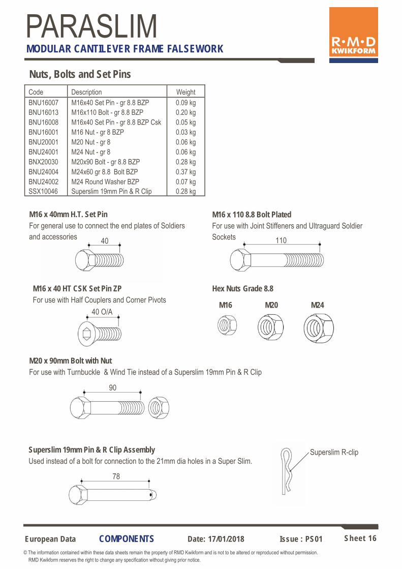
Nuts, Bolts and Set Pins
M16 x 40mm H.T. Set Pin For general use to connect the end plates of Soldiers and accessories
M16 x 110 8.8 Bolt Plated For use with Joint Stiffeners and Ultraguard Soldier Sockets
M16 x 40 HT CSK Set Pin ZP For use with Half Couplers and Corner Pivots
Hex Nuts Grade 8.8
M20 x 90mm Bolt with Nut For use with Turnbuckle & Wind Tie instead of a Superslim 19mm Pin & R Clip
Superslim 19mm Pin & R Clip Assembly Used instead of a bolt for connection to the 21mm dia holes in a Super Slim.
Superslim R-clip
M24 M20 M16
40 110
90
78
Code Description Weight BNU16007 M16x40 Set Pin - gr 8.8 BZP 0.09 kg BNU16013 M16x110 Bolt - gr 8.8 BZP 0.20 kg BNU16008 M16x40 Set Pin - gr 8.8 BZP Csk 0.05 kg BNU16001 M16 Nut - gr 8 BZP 0.03 kg BNU20001 M20 Nut - gr 8 0.06 kg BNU24001 M24 Nut - gr 8 0.06 kg BNX20030 M20x90 Bolt - gr 8.8 BZP 0.28 kg BNU24004 M24x60 gr 8.8 Bolt BZP 0.37 kg BNU24002 M24 Round Washer BZP 0.07 kg SSX10046 Superslim 19mm Pin & R Clip 0.28 kg
40 O/A
European Data Sheet 17 © The information contained within these data sheets remain the property of RMD Kwikform and is not to be altered or reproduced without permission. RMD Kwikform reserves the right to change any specification without giving prior notice.
Date: 17/01/2018 Issue : PS01
PARASLIM MODULAR CANTILEVER FRAME FALSEWORK
COMPONENTS
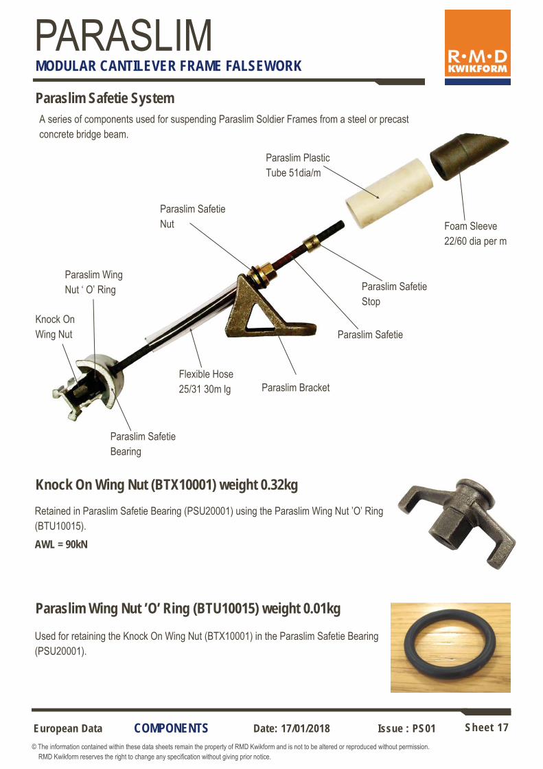
Paraslim Safetie System
Knock On Wing Nut
Knock On Wing Nut (BTX10001) weight 0.32kg
AWL = 90kN
Paraslim Wing Nut ’O’ Ring (BTU10015) weight 0.01kg
Used for retaining the Knock On Wing Nut (BTX10001) in the Paraslim Safetie Bearing (PSU20001).
A series of components used for suspending Paraslim Soldier Frames from a steel or precast concrete bridge beam.
Retained in Paraslim Safetie Bearing (PSU20001) using the Paraslim Wing Nut ’O’ Ring (BTU10015).
Paraslim Wing Nut ‘ O’ Ring
Paraslim Safetie Bearing
Flexible Hose 25/31 30m lg Paraslim Bracket
Paraslim Safetie Nut
Paraslim Safetie
Paraslim Safetie Stop
Paraslim Plastic Tube 51dia/m
Foam Sleeve 22/60 dia per m

European Data Sheet 18 © The information contained within these data sheets remain the property of RMD Kwikform and is not to be altered or reproduced without permission. RMD Kwikform reserves the right to change any specification without giving prior notice.
Date: 17/01/2018 Issue : PS01
PARASLIM MODULAR CANTILEVER FRAME FALSEWORK
COMPONENTS
Paraslim Safetie Bearing (PSU20001) weight 1.71kg
Retained in the Superslim Soldier porthole using an integral spring latch, the Paraslim Safetie Bearing houses and captivates the Knock O Wing Nut (BTX10001).
AWL = 65kN
Flexible Hose 25/31 - 30m long (BTU10002) weight 9.60kg
Used to protect and de-bond the Paraslim Bar Tie from wet concrete.
Paraslim Safetie Nut (PSU20002) weight 0.28kg
Used to suspend the Paraslim Bar Tie Assembly from the Paraslim Bracket 35 deg Cast (PSX10003) or the Paraslim Bracket 50 deg Cast (PSX10039). The integral rubber ‘O’ ring provides a tight seal between the Safetie Nut and the Paraslim Plas-tic Tube 51dia/m (PSU20006).
AWL = 65kN

European Data Sheet 19 © The information contained within these data sheets remain the property of RMD Kwikform and is not to be altered or reproduced without permission. RMD Kwikform reserves the right to change any specification without giving prior notice.
Date: 17/01/2018 Issue : PS01
PARASLIM MODULAR CANTILEVER FRAME FALSEWORK
COMPONENTS
Paraslim Bracket 35 deg Cast (PSX10003) weight 2.21kg
Attached to the top of a steel beam with an M24 Weld Stud & M24 Nut or to the top of a precast concrete beam using a M24 bolt, the Paraslim Bracket provides support to the Paraslim Bar Tie Assembly.
AWL = 55kN*
30 130
Tie angle range 30º to 43º
60
Plan Elevation
* Note: In two stage cantilever construction where the Paraslim Cast Bracket is buried at least 150mm into the first pour the allowable working load for the tie system can be increased to 65kN for the subsequent pours.
Paraslim Bracket 50 deg Cast (PSX10039) weight 2.12kg
Attached to the top of a steel beam with an M24 Weld Stud & M24 Nut or to the top of a precast concrete beam using a M24 bolt, the Paraslim Bracket provides support to the Paraslim Bar Tie Assembly.
AWL = 55kN*
30 133
60
Plan Elevation
Tie angle range 44º to 56º

European Data Sheet 20 © The information contained within these data sheets remain the property of RMD Kwikform and is not to be altered or reproduced without permission. RMD Kwikform reserves the right to change any specification without giving prior notice.
Date: 17/01/2018 Issue : PS01
PARASLIM MODULAR CANTILEVER FRAME FALSEWORK
Paraslim Safetie
Consists of 15mm Rapid Tie Bar cut to length with a Paraslim Safetie stop (PSU20003) 50mm from one end. The opposing end is sprayed green as a visible indicator for when the Safetie is fully engaged into the Paraslim Safetie Bearing (PSU20001).
AWL = 65kN
Paraslim Safetie Stop (PSU20003) weight 0.05kg
Prevents the Safetie Nut (PSU20002) from coming off the top end of the Safetie during tie removal and thus, as a result of further rotation, forcing retraction of the bottom end of the Safetie from the Safetie Bearing. Crimped onto the end of the 15mm Rapid Bar Tie Bar in the RMDK works when manufacturing Safeties.
Note: This item cannot be ordered separately
Paraslim Plastic Tube 51dia/m (PSU20006) weight 0.06kg
Used to protect the Paraslim Bar Tie from wet concrete and allow access to remove the Paraslim Safetie using the Paraslim Safetie Spanner (PSU20004).
Code Description Weight BTX30015 Bar Tie per m 15mm 1.50 kg PSU20003 Paraslim Safetie Stop 0.05 kg
COMPONENTS

European Data Sheet 21 © The information contained within these data sheets remain the property of RMD Kwikform and is not to be altered or reproduced without permission. RMD Kwikform reserves the right to change any specification without giving prior notice.
Date: 17/01/2018 Issue : PS01
PARASLIM MODULAR CANTILEVER FRAME FALSEWORK
Foam Sleeve 22/60 dia per m (FAU10141) weight 0.32kg
Used as a stopper to prevent wet concrete from entering the Paraslim Plastic Tube 51dia/m (PSU20006). Cut flush with the concrete surface during installation.
Paraslim Safetie Spanner (PSU20004) weight 4.23kg One end has a hex socket that engages with the Safetie Nut for use during the initial striking process by use of the integral slogging handles. The other end has a female thread that fits the top of the Safetie enabling the spanner to be connected to the top and the tie to be withdrawn, even when below the finished concrete surface. Also incorporates cross drilled holes enabling a short Rapid Bar Tie to be used as a T-bar.
COMPONENTS

European Data Sheet 22 © The information contained within these data sheets remain the property of RMD Kwikform and is not to be altered or reproduced without permission. RMD Kwikform reserves the right to change any specification without giving prior notice.
Date: 17/01/2018 Issue : PS01
PARASLIM MODULAR CANTILEVER FRAME FALSEWORK
Paraslim Wind Tie Assembly
COMPONENTS
The Paraslim wind tie assembly is used to prevent overturning of the Paraslim modules due to high winds gusting upwards. 2 No. wind tie assemblies are required per Paraslim module (fixed to the outermost Paraslim soldier frames).
Superslim 19mm Pin & R-clip (SSX10046)
2 No. Quicklink 10mm (AGU20013)
10mm Turnbuckle 222-320mm (AGU20016)
Cable Tie
Galvanised Chain 8mm x 3050mm (AGU20015)
Webtie Edge Protector (PSX10014) Quicklink 10mm (AGU20013)
Paraslim Restraint Hook (PSU20009)
Ensure bolt is tightened against
top of flange
Paraslim Restraint Hook (PSU20009) weight 1.02kg
AWL = 12kN
Used at the end of the Paraslim wind tie assembly to connect the restraint chain to the bottom flange of the bridge girder.
35-7
0 90
Side View Plan View
Captive Set Pin
75
119

European Data Sheet 23 © The information contained within these data sheets remain the property of RMD Kwikform and is not to be altered or reproduced without permission. RMD Kwikform reserves the right to change any specification without giving prior notice.
Date: 17/01/2018 Issue : PS01
PARASLIM MODULAR CANTILEVER FRAME FALSEWORK
COMPONENTS
Quicklink 10mm (AGU20013) weight 0.13kg
AWL = 12kN
Part of the Wind Tie Assembly, the Quicklink 10mm is used to connect the Paraslim Restraint Hook (PSU20009) to the Galvanised Chain 8mm x 3050mm (AGU20015) and the 10mm Turnbuckle 222-320mm (AGU20016) to the Paraslim soldier frame.
Galvanised Chain 8mm x 3050mm (AGU20015) weight 3.29kg/m
10mm Turnbuckle 222-320mm (AGU20016) weight 0.45kg
AWL = 12kN
Connected between the Paraslim Restraint Hook (PSU20009) and the 10mm Turnbuckle 222-320mm (AGU20016) in the Paraslim Wind Tie Assembly.
Used to tension the 8mm chain bracing in the Paraslim Wind Tie Assembly. 1 No required per brace. Important! ensure 8mm Nyloc Nuts are used on fork end pins and max extension of 55mm at each end is not exceeded.
AWL = 12kN
Webtie Edge Protector (PSX10014) weight 0.01kg Used to protect the paintwork on the edge of the bottom flange of the bridge girder.
Superslim 19mm Pin & R-clip (SSX10046) weight 0.29kg Used to connect the 8mm chain bracing to the Superslim soldier frame in the
Paraslim Wind Tie Assembly.
AWL = 50kN

European Data Sheet 24 © The information contained within these data sheets remain the property of RMD Kwikform and is not to be altered or reproduced without permission. RMD Kwikform reserves the right to change any specification without giving prior notice.
Date: 17/01/2018 Issue : PS01
PARASLIM MODULAR CANTILEVER FRAME FALSEWORK
COMPONENTS
Ultraguard Barriers The Ultraguard barrier is simple to use and to erect. The barrier itself complies with the latest European standards for Temporary Edge Protection Systems (Classification A) to EN 13374:2004.
Code Description Weight SAX12550 Ultraguard Barrier 2550mm 17.3 kg SAX13150 Ultraguard Barrier 3150mm 25.0 kg
Ultraguard Handrail Post 1200mm (SAX11200) weight 2.20kg A lightweight aluminium post with an integral steel anti-lift plate. The post has an ‘easy fit’ socket connection that is used throughout the Ultraguard range of components.
Ultraguard Aluminium Beam Bracket (SAX10005) weight 4.17kg Used on secondary aluminium beams to a maximum of 100mm wide. The clamp is designed to take the Ultraguard Post (SAX11200) or a 48.3mm diameter Scaffold Tube that is secured using an integral captive wing nut arrangement.
Ultraguard Soldier Socket (SAX10012) weight 4.74kg Allows Ultraguard barrier system to be used with Superslim Soldiers as horizontal members. The socket is bolted to the end of the Superslim Soldier using 2 No. M16x110 gr8.8 Bolts and M16 Nuts ( BNU16013 + BNU16001).

European Data Sheet 25 © The information contained within these data sheets remain the property of RMD Kwikform and is not to be altered or reproduced without permission. RMD Kwikform reserves the right to change any specification without giving prior notice.
Date: 17/01/2018 Issue : PS01
PARASLIM MODULAR CANTILEVER FRAME FALSEWORK
COMPONENTS
Twin Pronged Table C-Hook (ASX10067) weight 996.0kg
3890
3209
300 TYP 100 100
4965 79 - 2079
in 100mm increments 2886
5404
Lifting equipment used for crane handling Paraslim modules of up to 4000kg. Use in conjunction with C-Frame Chain Assembly (ASX10042) and refer to Equipment Guidance Notes UIX10606 for information regarding safe use.
This ‘C’ Hook folds down to 985h x 3760w x 1420w for transportation.
Elevation
End View
900
2805
Plan Layout 21
32
1190

European Data Sheet 26 © The information contained within these data sheets remain the property of RMD Kwikform and is not to be altered or reproduced without permission. RMD Kwikform reserves the right to change any specification without giving prior notice.
Date: 17/01/2018 Issue : PS01
PARASLIM MODULAR CANTILEVER FRAME FALSEWORK
Paraslim Weld Stud & Ferrule M24x50 (PSX10001) weight 0.25kg
Stud Material Weld studs are manufactured from low-carbon steel grade St 37-3K conforming to DIN standard 17100 offering excellent weldability. Mechanical properties are in accordance with DIN-ISO 898 Sheet1, grade 4.8: Yield stress:
340 N/mm2, tensile strength: 420 N/mm2, elongation: 14 %.
AWL = 60kN tension & 43kN shear (factor of safety 2:1 on yield).
Stud Welding It is the responsibility of the customer to verify the adequacy of any weld procedure used for the attachment of the threaded studs onto the main steelwork and to ensure that all such studs are individually tested. Welding of the studs can be by the Drawn Arc process with procedures generally in accordance with DIN 8563 pt.10 (NOTE: Excluding testing requirements) or by M.M.A., M.A.G. or F.C.A.W. with procedures in accordance with BS 288 pt.3.
The drawn-arc process is the preferred method used to attach weld studs. The stud is inserted into an applicator tool, which is connected to one terminal of a substantial electrical supply. The beam to which the stud will be connected is attached to the other terminal. The bottom end of each stud is slightly pointed and contains a small, embedded slug of aluminium metal. When the operator applies the applicator to the beam an electric arc is struck between the two components. The heat of the arc melts both the end of the stud and the surface of the beam with the aluminium acting as a flux. The resultant molten weld metal is retained in situ by a small ceramic ferrule placed around the stud prior to application.
In addition to visual inspection of every weld, each stud must be subjected to an axial proof load of 100kN prior to use. Records should be kept of all inspection and testing.
COMPONENTS

European Data Sheet 27 © The information contained within these data sheets remain the property of RMD Kwikform and is not to be altered or reproduced without permission. RMD Kwikform reserves the right to change any specification without giving prior notice.
Date: 17/01/2018 Issue : PS01
PARASLIM MODULAR CANTILEVER FRAME FALSEWORK
Stud Weld Testing If the correct procedures are used the drawn-arc process produces a reliable full strength butt weld over the entire cross section of each stud. Poor weld quality will result if incorrect current/voltage are used and if operatives attempt to weld the studs when too much moisture is present (i.e. in the rain or before the steel is dry after-wards). There are few opportunities for a half-way-house in quality; when the weld is defective it exhibits very low strength, otherwise the stud is good.
Stud Weld Testing Equipment
M24x475mm long All Thread Rod gr8.8 (PSX10041)
RMDK Hydraulic Test Kit (BTX10027) calibrated for 100kN max
M24 Hex Nut gr8.8 (BNU24001)
2 No. 75x75x6x26 Plate Washers (BNX20019)
M24x48 long High Yield Coupler (PSX10042)
Open Sided Test Stool (PSX10040)
Baseplate 100mm square
Paraslim Weld Stud M24x50 (PSX10001)
RMDK have developed a simple tensile test using standard off the shelf equipment. A tensile test load of 100kN is applied to each stud subsequent to welding and prior to use. The test setup is shown below.
COMPONENTS

European Data Sheet 28 © The information contained within these data sheets remain the property of RMD Kwikform and is not to be altered or reproduced without permission. RMD Kwikform reserves the right to change any specification without giving prior notice.
Date: 17/01/2018 Issue : PS01
PARASLIM MODULAR CANTILEVER FRAME FALSEWORK
COMPONENTS
Cast in Socket Anchor M24 x 200 (FAU10145)
M24x60 gr8.8 Bolt (BNU24004) with M24 Round Washer (BNU24002)
160
Cast-in Socket Anchor M24x200 (FAU10145) A cast-in anchor for use in precast concrete edge beams or insitu concrete
structures.
See below for AWL (figures shown are for C40/50 Un-cracked Concrete)
Tie Load Limited by Cast-in Socket Anchor
Tie L
oad
(kN)
Tie Angle
55
50
45
40
35
30 30 35 40 45 50 55

European Data Sheet 29 © The information contained within these data sheets remain the property of RMD Kwikform and is not to be altered or reproduced without permission. RMD Kwikform reserves the right to change any specification without giving prior notice.
Date: 17/01/2018 Issue : PS01
PARASLIM MODULAR CANTILEVER FRAME FALSEWORK
Special Paraslim Bracket Connected to Sheet Piles by Customer’s Welding
Paraslim Safetie Nut
Paraslim Sheet Pile Bracket. Customer to Weld to Pile Face With 4mm Fillet Weld.
25/31 Flexible Hose
Customer to Make Grout Tight With Denzo Tape or Similar
Paraslim Safetie
Ø60mm Hole in Sheet Pile Face By Customer
Customer’s Sheet Piles
Customer to Seal With Expanding Foam or Similar
Paraslim Plastic Tube 51dia
APPLICATIONS
Paraslim Bracket Fixed to Steel Beam with M24x50 Shear Stud
160
M24 Nut on Paraslim Cast Bracket Over RMDK M24x50 Weld Stud, Weld-ed to Beam Flange by Others
Grout Seal Tube with Customer’s Expanding Foam
Customer’s Timber Notched Locally Around Ties
25/31 Flexible Hose
Paraslim Plastic Tube 51 Dia
Foam Sleeve 22/60
Paraslim Bracket Cast
Paraslim Safetie & Nut
Note: When fixing the Paraslim Cast Bracket to the Steel Girder, the M24 Nut on the Weld Stud should be finger tight and then given 1/4 of a turn with a spanner - under no circumstances should this nut be torqued.

European Data Sheet 30 © The information contained within these data sheets remain the property of RMD Kwikform and is not to be altered or reproduced without permission. RMD Kwikform reserves the right to change any specification without giving prior notice.
Date: 17/01/2018 Issue : PS01
PARASLIM MODULAR CANTILEVER FRAME FALSEWORK
Standard arrangement
APPLICATIONS
Detail 1 - Standard Arrangement for Steel Girders over Live Traffic
Webtie Edge Protector
Paraslim Forkend & Turnbuckle
Plan lacing & bracing
Push-pull Corner Angle
1800
ply h
oard
ing
Standard arrangementfor box girders
Detail 2 - Standard Arrangement for Trapezoidal Box Girders - no Live Traffic
Kentledge for stability
European Data Sheet 31 © The information contained within these data sheets remain the property of RMD Kwikform and is not to be altered or reproduced without permission. RMD Kwikform reserves the right to change any specification without giving prior notice.
Date: 17/01/2018 Issue : PS01
PARASLIM MODULAR CANTILEVER FRAME FALSEWORK
APPLICATIONS
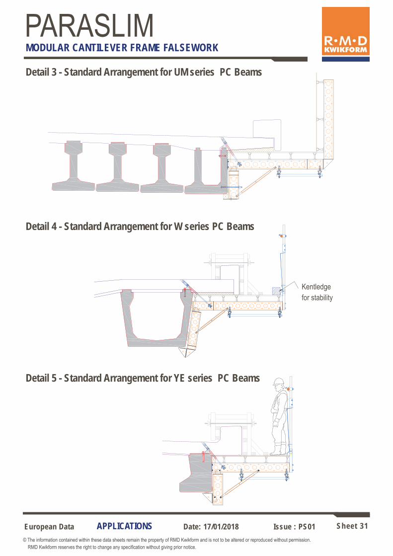
Detail 3 - Standard Arrangement for UM series PC Beams
Detail 4 - Standard Arrangement for W series PC Beams
Kentledge for stability
Detail 5 - Standard Arrangement for YE series PC Beams

European Data Sheet 32 © The information contained within these data sheets remain the property of RMD Kwikform and is not to be altered or reproduced without permission. RMD Kwikform reserves the right to change any specification without giving prior notice.
Date: 17/01/2018 Issue : PS01
PARASLIM MODULAR CANTILEVER FRAME FALSEWORK
!
APPLICATIONS
Detail 6 - Soldier Undercarriage Arrangement for Shallow Bridge Girders
Plan lacing & bracing S/Slim Turnbuckle
Minima Tie Plate 15
Tie to bottom flange 2 No. required per module
Ø15 Rapid Bar Tie x 1.3m Minima Edge Tie Bearing
Customer’s timber pack banded to vertical Soldier - designed for R2 reaction shown
Detail 7 - No Undercarriage Arrangement for Very Shallow Bridge Girders
0.6m scaffold tube Tube handrail c/w 2”x2” 90º coupler
External joint coupler
Ultraguard Post & Barrier

European Data Sheet 33 © The information contained within these data sheets remain the property of RMD Kwikform and is not to be altered or reproduced without permission. RMD Kwikform reserves the right to change any specification without giving prior notice.
Date: 17/01/2018 Issue : PS01
PARASLIM MODULAR CANTILEVER FRAME FALSEWORK
APPLICATIONS
Detail 8 - Heavy Duty Arrangement for Wide or Deep Cantilevers
Detail 9 - Heavy Duty Arrangement for YE Precast Beams - Trough Construction

European Data Sheet 34 © The information contained within these data sheets remain the property of RMD Kwikform and is not to be altered or reproduced without permission. RMD Kwikform reserves the right to change any specification without giving prior notice.
Date: 17/01/2018 Issue : PS01
PARASLIM MODULAR CANTILEVER FRAME FALSEWORK
APPLICATIONS
Detail 10 - Standard Arrangement for Sheet Piling 0.6m scaffold tube
External joint coupler
Ultraguard Post & Barrier
Ultraguard Soldier Socket
Detail 11 - Paraslim Access Platform For details of the Paraslim Access Platform connections please refer to Appendix ‘A’.

European Data Sheet 35 © The information contained within these data sheets remain the property of RMD Kwikform and is not to be altered or reproduced without permission. RMD Kwikform reserves the right to change any specification without giving prior notice.
Date: 17/01/2018 Issue : PS01
PARASLIM MODULAR CANTILEVER FRAME FALSEWORK
DESIGN DATA
Design Paraslim consists of triangular frames laced together to form modules. A single diagonal tie from a porthole in the top chord of the triangular frame to a bracket bolted or welded to the support structure suspends each frame in the module. All other reaction points (R1, R2 & R3) use simple bearing and are not positively connected.
Member Forces and Reaction Distribution The member forces and reactions are controlled by two factors; the vertical loads on the system and the outboard moment on the frame. The only vertical support is provided by the Paraslim Tie. Because this is inclined a horizontal force is generated which is resisted by compression at R1. If the outboard moment is low compared with the vertical load the outboard moment is resisted by a couple generated between R1 & R2. This produces compression at R2 and relives the compression due to the tie load at R1. If the outboard moment is high relative to the vertical load the compression at R1 decreases until it reaches zero. As it cannot take tension any further moment causes the reaction distribution to change from a horizontal reaction at R1 to a vertical reaction at R3. On steel bridge beams reaction R3 is provided by packing to the underside of the top flange. On concrete edge beams it is provided by the undercarriage hooking underneath the beam. The side formwork will affect the distribution of forces and this should be considered during the design. The distribution of forces and reactions should be calculated using either simple static or elastic analysis. Simple static analysis is best carried out using a bespoke spreadsheet calculator and elastic analysis is carried out using frame analysis software. Inboard Rotation As well as outboard rotation the Paraslim frame must also be checked for inboard rotation caused by vertical loads inboard of the porthole bearing support plus wind forces on the hand-rail/hoarding and underside of the module. As the point of vertical support for the Paraslim frame is the Porthole Bearing this is the point around which the frame will rotate during any condition of instability. A stability check is best done by simple moments. A minimum FOS of 1.2 against overturning should be considered. Kentledge or wind ties to the support structure should be used where necessary.
Tie Load
R1
Vf
Outboard Moment
R2
R3
Rotation
Inboard Outboard
Porthole Bearing

European Data Sheet 36 © The information contained within these data sheets remain the property of RMD Kwikform and is not to be altered or reproduced without permission. RMD Kwikform reserves the right to change any specification without giving prior notice.
Date: 17/01/2018 Issue : PS01
PARASLIM MODULAR CANTILEVER FRAME FALSEWORK
DESIGN DATA
Side shutters Three types of side shutter are generally used: Considering the horizontal forces and moments caused by the side shutter: Type X All taken by permanent structure, none taken by Paraslim. Type Y All taken by Paraslim. Type Z Shared by permanent structure and Paraslim. The type selected can have a significant affect on the distribution of forces and reactions and it is important the shutter erected on site matches that detailed by the designer.
Wind Loading Wind forces should be calculated using a wind code appropriate to the location. Appropriate force coefficients are as below.
Note. Wind uplift on structures such as Paraslim is not well covered by design standards. Correlation is taken from advice for canopies with a Cf value of 0.9 being taken if the wind can pass freely underneath and 1.3 in all other situations. Normally the wind will be able to pass freely underneath but in rare situations the wind can be deflected up at a steep angle so that it hits the underside of the Paraslim. This can be because of a large obstruction under the structure or because it is at the top of a very steep embankment or cliff. In these case a Cf value of 1.3 should be used.
Type ‘X’ Type ‘Y’ Type ‘Z’
Wind Gust Profile
Wind Profile Hoarding, Guardrail & Toe Boards
Wind Profile Soffit Edge
Force Coefficients, Cf Hoarding, Guardrails & Toe Board = 1.8 - see BS 5975 17.5.1.15.4
Edge of soffit formwork = 2.2 - see BS 5975 17.5.1.15.2 (b)
Up-gust on canopy = 0.9 or 1.3 - treated as canopy ‘half or fully blocked’ at downwards eaves. See note below.

European Data Sheet 37 © The information contained within these data sheets remain the property of RMD Kwikform and is not to be altered or reproduced without permission. RMD Kwikform reserves the right to change any specification without giving prior notice.
Date: 17/01/2018 Issue : PS01
PARASLIM MODULAR CANTILEVER FRAME FALSEWORK
Allowable Tie Loads The allowable tie load is dependant on the capacity of the tie, the anchor bracket and the method of fixing the anchor bracket to the existing structure.
Maximum allowable tie load of a Paraslim Bracket when welded or bolted to a steel structure with M24 x 50 weld studs = 55kN
The maximum allowable tie load of the Paraslim Bracket when bolted to a cast in fixing on a concrete structure will depend on the capacity of the anchor.
The tie itself has an allowable capacity of 65kN but this can only be achieved in two stage cantilever construction where the Paraslim Bracket is fully encased in the first pour by at least 150mm and the concrete has achieved a concrete strength of at least 25N/mm2.
Bracket Reactions
Module Layout In order to provide redundancy wherever possible modules should be detailed with three or more frames. Two frames modules should only be detailed for structure with tight vertical or horizontal curves.
DESIGN DATA
Rº
V kN
N kN R kN
Due to bracket geometry, bracket reactions:
30-44 degree Brackets
N = 94 x Tie Load x Sin (69.23 - R)/120 R = Vertical tie component + N V = Tie load x Cos R
30-56 degree Brackets
N = 104 x Tie Load x Sin (83 - R)/120 R = Vertical tie component + N V = Tie load x Cos R

European Data Sheet 38 © The information contained within these data sheets remain the property of RMD Kwikform and is not to be altered or reproduced without permission. RMD Kwikform reserves the right to change any specification without giving prior notice.
Date: 17/01/2018 Issue : PS01
PARASLIM MODULAR CANTILEVER FRAME FALSEWORK
Deflection Frame analysis for Paraslim schemes shows the RMD Kwikform equipment to be relatively stiff and typically gives primary deflection values in the region of 4mm at the concrete face. There will be significant and additive secondary deflections caused by other factors. Their sum will likely exceed the primary deflection and although RMDK have no responsibility to calculate values, we have much experience in this field and should communicate such information to users of the system so that appropriate soffit pre-setting allowances may be made by the Customer during erection. Any deflection of the permanent works will allow rotational deflection of the Paraslim system. Below are typical causes and values of these deflections.
Lateral deflection of the bottom flange of the girder (3mm).
Lateral deflection of the web at the lower horizontal web support (2mm)
The sum of these deflections is 5mm. The deflection of the soffit at the cantilever edge however will be amplified based upon the ratio of the vertical distance between the reaction points on the girder web and the length of concrete cantilever. If this ratio is 2 than the resultant deflection at the edge of the cantilever due to the secondary effects will be 10mm. This is additional to the 4mm calculated in the frame analysis. The total deflection will hence be in the region of 14mm. Further rotational deflection will result at any joint between the Horizontal Superslims if the bolts in the joint have not been torqued up to 140Nm.
DESIGN DATA
European Data Sheet 39 © The information contained within these data sheets remain the property of RMD Kwikform and is not to be altered or reproduced without permission. RMD Kwikform reserves the right to change any specification without giving prior notice.
Date: 17/01/2018 Issue : PS01
PARASLIM MODULAR CANTILEVER FRAME FALSEWORK
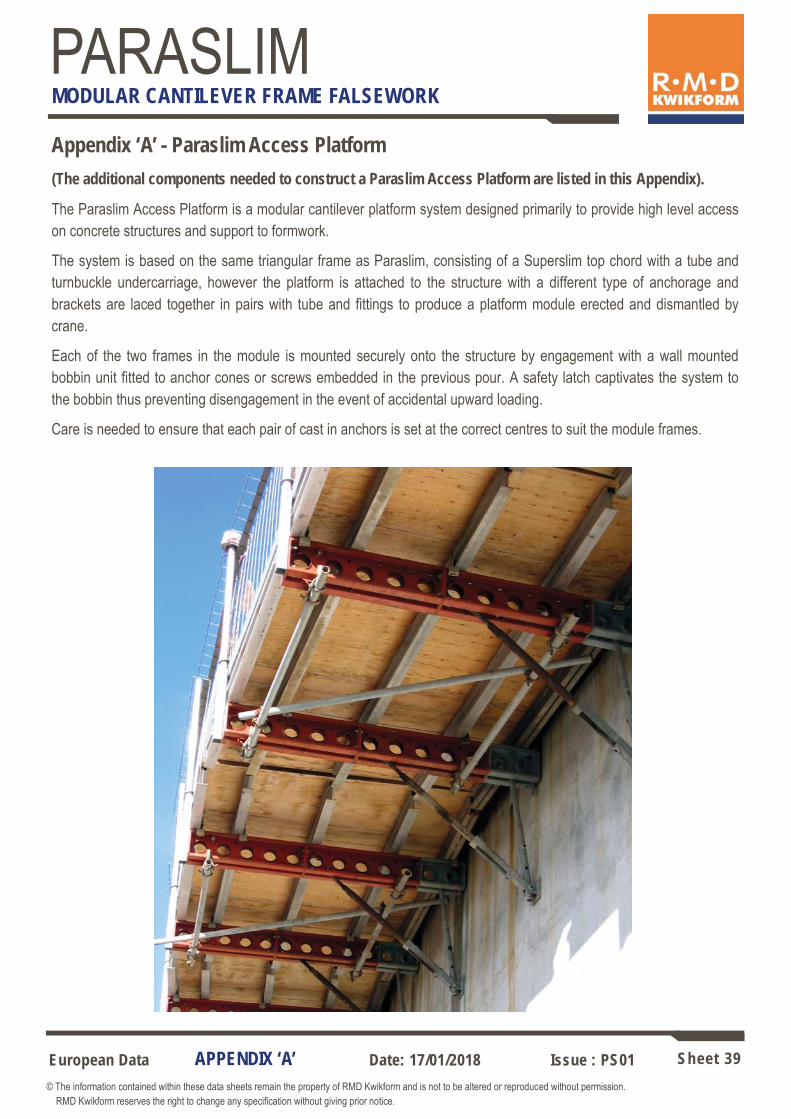
Appendix ‘A’ - Paraslim Access Platform (The additional components needed to construct a Paraslim Access Platform are listed in this Appendix).
The Paraslim Access Platform is a modular cantilever platform system designed primarily to provide high level access on concrete structures and support to formwork.
The system is based on the same triangular frame as Paraslim, consisting of a Superslim top chord with a tube and turnbuckle undercarriage, however the platform is attached to the structure with a different type of anchorage and brackets are laced together in pairs with tube and fittings to produce a platform module erected and dismantled by crane.
Each of the two frames in the module is mounted securely onto the structure by engagement with a wall mounted bobbin unit fitted to anchor cones or screws embedded in the previous pour. A safety latch captivates the system to the bobbin thus preventing disengagement in the event of accidental upward loading.
Care is needed to ensure that each pair of cast in anchors is set at the correct centres to suit the module frames.
APPENDIX ‘A’

European Data Sheet 40 © The information contained within these data sheets remain the property of RMD Kwikform and is not to be altered or reproduced without permission. RMD Kwikform reserves the right to change any specification without giving prior notice.
Date: 17/01/2018 Issue : PS01
PARASLIM MODULAR CANTILEVER FRAME FALSEWORK
APPENDIX ‘A’
Superslim Soldier 360mm OE - Post 2002 (SSU10035) weight 11.7kg Used as part of the primary beam on the Superslim support frame. The open end facilitates location of the platform onto the Superslim O/E M24 Cone Bobbin (SSX10061).
For max loads with Superslim O/E M24 Cone Bobbin see performance graph - sheet 40.
180
125
176
106
225
360
60 60 120 120
90 90 180
42
126
80
225
176
70
24
6 No 18Ø holes
27Ø hole
6 No 21Ø holes through
100Ø
10 10 3.5
Note: Tension load capacity does not apply when attaching the Superslim O/E M24 Cone Bobbin to the central 27mm dia. hole of a non-open ended Superslim Soldier. AWL to follow.
*
B
A

European Data Sheet 41 © The information contained within these data sheets remain the property of RMD Kwikform and is not to be altered or reproduced without permission. RMD Kwikform reserves the right to change any specification without giving prior notice.
Date: 17/01/2018 Issue : PS01
PARASLIM MODULAR CANTILEVER FRAME FALSEWORK
APPENDIX ‘A’
Creates a captivated connection when seating a (post 2002) 360mm OE soldier over the Superslim O/E M24 Cone Bobbin, creating simple loading / access platforms etc.
Superslim Safety Latch (SSX10048) Weight 1.39kg
Typical Arrangement
287
181
22
2 No 24mm Ø holes though
Latch in locked position
Latch in unlocked position
360mm OE Soldier (post 2002 type)
M24 Anchor Cone & Ascent Anchor
19mm Pin & R Clip
M24 Cone Bobbin
Allowable Working Loads for Superslim O/E M24 Cone Bobbin
Shea
r Loa
d on
Bob
bin
(kN)
Tension Load on Bobbin (kN)
50
40
30
20
10
0 0 10 20 30 40 50 60 70 80

European Data Sheet 42 © The information contained within these data sheets remain the property of RMD Kwikform and is not to be altered or reproduced without permission. RMD Kwikform reserves the right to change any specification without giving prior notice.
Date: 17/01/2018 Issue : PS01
PARASLIM MODULAR CANTILEVER FRAME FALSEWORK
APPENDIX ‘A’
Rapidclimb 45kN Cone (RCX10009) weight 1.62 kg Cast into the wall together with the Ascent Anchor Plate (AGX10028) to enable connection of the Superslim O/E M24 Cone Bobbin (SSX10061). It is retrieved after use. Note! Ensure cone surfaces are coated with Anchor Screw Grease to facilitate removal.
M24 Thread
Cross Section Showing Stop Pin
100
50Ø
60Ø
58
Allowable Working Load = 45kN shear & 80kN tension
Code Description Weight
HTX24280 HTX24200 HTX24140 HTX10015 HTX10013
Anchor Screw M24 x 280 Anchor Screw M24 x 200 Anchor Screw M24 x 140 Extractor Key Head M24 Extractor Key Arm
1.45 kg 1.11 kg 0.88 kg 0.34 kg 3.60 kg
200
43Ø
140
41
280
M24 Anchor Screws A fully recoverable alternative to the cone for fixing to the wall.
Superslim O/E M24 Cone Bobbin (SSX10061) weight 0.5kg Used in conjunction with the Rapidclimb Anchor Cone (RCX10009) and the Ascent Anchor Plate (AGX10028) to secure the Superslim Support Frame to the wall.
24Ø
36 across flats 45 10 12 16
3
42Ø
59Ø AWL - see performance
graph (sheet 7)

European Data Sheet 43 © The information contained within these data sheets remain the property of RMD Kwikform and is not to be altered or reproduced without permission. RMD Kwikform reserves the right to change any specification without giving prior notice.
Date: 17/01/2018 Issue : PS01
PARASLIM MODULAR CANTILEVER FRAME FALSEWORK
APPENDIX ‘A’
Rapidclimb Extractor Key (RCX10031) weight 0.45 kg Used to remove Rapidclimb cones to allow re-use. The key can be captivated to the cone using a M24x60 set pin to prevent movement of the key when using a 36AF spanner on the hex head if required.
61Ø 41
M24 Thread
Rapidclimb 45kN Cone Retainer (RCX10020) weight 0.12kg
Rapidclimb Cone Retainer Key (RCX10021) weight 0.05kg
Used to attach the 45kN Anchor Cone or 30kN anchor screw to the shutter prior to pouring. This is nailed to the form face and the anchor is hand tightened onto it.
A 14A/F key used to extract the Cone Retainer from the Anchor Cone after the pouring process.
80
A consumable M24 gr8.8 anchor used with the Rapidclimb 45kN Anchor Cone (RCX10009).
Ascent Anchor Plate (AGX10028) weight 1.12kg
95x95x10 thick plate
36
25Ø
58Ø 20 40
14.1
A/F

European Data Sheet 44 © The information contained within these data sheets remain the property of RMD Kwikform and is not to be altered or reproduced without permission. RMD Kwikform reserves the right to change any specification without giving prior notice.
Date: 17/01/2018 Issue : PS01
PARASLIM MODULAR CANTILEVER FRAME FALSEWORK
Contact Details: International Offices Europe
Head Office – United Kingdom
RMD Kwikform, Brickyard Road,
Aldridge, Walsall WS9 8BW, UK.
Tel: +44 1922 743743
Fax: +44 1922 743400
Email: [email protected]
Ireland
RMD Kwikform,
Ballyboggan Road,
Finglas, Dublin 11, Ireland.
Tel: +353 1 830 2500
Fax: +353 1 830 2741
Email: [email protected]
Spain
RMD Kwikform,
Paseo del Club Deportivo s/n,
Urbanización La Finca, Edif.3, 1O Izda.
Somosaguas, 28223 Pozuelo de Alarcón Madrid.
Tel: +34 91 555 61 04
Fax: +34 91 555 47 45
Email: [email protected]
Portugal RMD Kwikform,
Av. 25 de Abril, 32 - 1 Esq,
2870 - 150 Montijo, Portugal.
Tel: +351 21 232 86 88
Fax: +351 21 231 57 15
Email: [email protected]
Sweden RMD Kwikform
Husie Kyrkoväg 49, Box 14015,
200 24 Malmo, Sweden.
Tel: +46 4049 17 50
Fax: +46 4049 46 14
Email: [email protected]
Asia Pacific
Australia
RMD (Australia) Pty. Ltd.
PO Box 169, Melrose Park,
South Australia, 5039.
Tel: +61 8 8179 8200
Fax: +61 8 8179 8201
Email: [email protected]
Hong Kong
RMD Kwikform,
22/F Excel Center,
483A Castle Peak Road,
Cheung Sha Wan, Kowloon, Hong Kong.
Tel: +852 2415 4882
Fax: +852 2745 0232
Email: [email protected]
New Zealand RMD (New Zealand) Ltd.
PO Box 22-316, 101-105 Station Road,
Otahuhu, Auckland 6, New Zealand.
Tel: +64 9 276 5955
Fax: +64 9 276 6732
Email: [email protected]
Philippines
RMD Kwikform,
Units 2406-2409,
Raffles Corporate Center,
F. Ortigas Jr. Road,
Ortigas Center,
Pasig City,
Philippines.
Tel: +632 696 7635
Fax: +632 661 6456
Email: [email protected]
Middle East
UAE RMD Kwikform,
PO Box 5801, Sharjah,
United Arab Emirates.
Tel: +971 6 5534173
Fax: +971 6 5534327
Email: [email protected]
Qatar RMD Kwikform,
PO Box 405, Doha, Qatar.
Tel: +974 467 5925
Fax: +974 465 3282
Email: [email protected]
Bahrain RMD Kwikform,
C/O CGH ,
Building 829, Flat 11,
Block 408, Sanabis,
Kingdom of Bahrain.
Tel: +973 1738 2724
Fax: +973 1755 8711
Email: [email protected]
Oman RMD Kwikform Oman LLC
PO Box 889
Post Code 115
Muscat
Sultanate of Oman
Tel: +968 2463 6776
Fax: +968 2447 8328
Lebanon
RMD Kwikform,
Ishaac Bin Honein Street,
Ashrafieh, Nr, Beirut, Lebanon.
Tel: +961 545 0214
Fax: +961 595 5387
Email: [email protected]
Related Documents