www.belimo.com T2-GK24G-SR • en • v1.1 • 03.2012 • Subject to changes 1 / 6 Technical data sheet GK24G-SR Technical data Electrical data Nominal voltage AC 24 V, 50/60 Hz / DC 24 V Nominal voltage range AC 19.2 ... 28.8 V / DC 21.6 ... 28.8 V Power consumption In operation At rest For wire sizing 11 W @ nominal torque 3 W 21 VA (l max 20 A @ 5 ms) Connection Cable 1 m, 4 x 0.75 mm 2 (halogen-free) Parallel operation Yes (note the performance data) Functional data Torque Inhibiting torque ≥40 Nm ≥40 Nm Control Control signal Y DC 0 … 10 V, input impedance 100 k� Operating range DC 2 ... 10 V Position feedback (Measuring voltage U) DC 2 ... 10 V, max. 0.5 mA Setting emergency position (POP) 0...100%, adjustable (POP rotary button) Position accuracy ±5% Direction of rotation Motor Emergency setting position As an option with switch / Reversible with switch 0 ... 100% Direction of rotation Y = 0 V At switch position 1 and 0 , respectively Manual override Gearing latch disengaged with push button Angle of rotation Max. 95° , can be limited at both ends with adjustable mechanical end stops Running time Motor Emergency setting position 150 s / 90° 35 s @ 0 ... 50°C Sound power level Motor Emergency setting position ≤53 dB (A) @ 90 s running time ≤52 dB (A) @ 150 s running time ≤61 dB (A) Position indication Mechanical, pluggable Safety Protection class III Safety extra-low voltage UL Class 2 Supply Degree of protection IP66 NEMA 4, UL Enclosure Type 4 EMC CE according to 2004/108/EC Certification Certified to IEC/EN 60730-1 and IEC/EN 60730-2-14 cULus according to UL 60730-1A and UL 60730-2-14 and CAN/CSA E60730-1:02 Mode of operation Type 1.AA Rated impulse voltage 0.8 kV Control pollution degree 4 Modulating SuperCap rotary actuator with emergency setting function and extended functionalities in the IP66 protective housing for adjusting air dampers in ventilation and air-conditioning systems for building services installations and in laboratories • For air dampers up to approx. 8 m 2 • Torque 40 Nm • Nominal voltage AC/DC 24 V • Control: modulating DC 0 ... 10 V • Position feedbac DC 2 ... 10 V Position feedbac DC 2 ... 10 V • Design life SuperCaps 15 years Optimum weather protection (for use in ambient temperatures up to –40°C, there is a separate actuator available with built-in heater ex wors) . . . . . . . . . . . . . . . . . . . . . . . . . . . . . . . . . . . . . . Terms and abbreviations POP = Power off position / emergency setting position PF = Power fail delay time / bridging time

Welcome message from author
This document is posted to help you gain knowledge. Please leave a comment to let me know what you think about it! Share it to your friends and learn new things together.
Transcript
www.belimo.com T2-GK24G-SR • en • v1.1 • 03.2012 • Subject to changes 1 / 6
Technical data sheet GK24G-SR
Technical data
Electrical data Nominal voltage AC 24 V, 50/60 Hz / DC 24 VNominal voltage range AC 19.2 ... 28.8 V / DC 21.6 ... 28.8 VPower consumption In operation
At restFor wire sizing
11 W @ nominal torque3 W21 VA (lmax 20 A @ 5 ms)
Connection Cable 1 m, 4 x 0.75 mm2 (halogen-free)Parallel operation Yes (note the performance data)
Functional data TorqueInhibiting torque
≥40 Nm≥40 Nm
Control Control signal Y DC 0 … 10 V, input impedance 100 k�Operating range DC 2 ... 10 V
Position feedback (Measuring voltage U) DC 2 ... 10 V, max. 0.5 mASetting emergency position (POP) 0...100%, adjustable (POP rotary button)Position accuracy ±5%Direction of rotation Motor
Emergency setting positionAs an option with switch / Reversible with switch 0 ... 100%
Direction of rotation Y = 0 V At switch position 1 and 0 , respectivelyManual override Gearing latch disengaged with push buttonAngle of rotation Max. 95° , can be limited at both ends with
adjustable mechanical end stopsRunning time Motor
Emergency setting position150 s / 90°35 s @ 0 ... 50°C
Sound power level Motor
Emergency setting position
≤53 dB (A) @ 90 s running time≤52 dB (A) @ 150 s running time≤61 dB (A)
Position indication Mechanical, pluggable
Safety Protection class III Safety extra-low voltageUL Class 2 Supply
Degree of protection IP66NEMA 4, UL Enclosure Type 4
EMC CE according to 2004/108/ECCertification Certified to IEC/EN 60730-1 and IEC/EN 60730-2-14
cULus according to UL 60730-1A and UL 60730-2-14and CAN/CSA E60730-1:02
Mode of operation Type 1.AARated impulse voltage 0.8 kVControl pollution degree 4
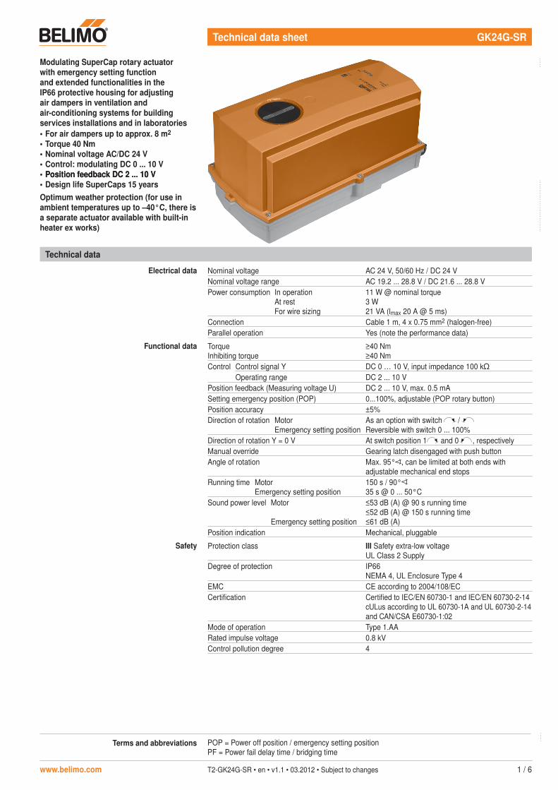
Modulating SuperCap rotary actuator with emergency setting function and extended functionalities in the IP66 protective housing for adjusting air dampers in ventilation and air-conditioning systems for building services installations and in laboratories• For air dampers up to approx. 8 m2
• Torque 40 Nm• Nominal voltage AC/DC 24 V• Control: modulating DC 0 ... 10 V• Position feedbac�� DC 2 ... 10 VPosition feedbac�� DC 2 ... 10 V• Design life SuperCaps 15 yearsOptimum weather protection (for use in ambient temperatures up to –40°C, there is a separate actuator available with built-in heater ex wor��s)
. . . . . . . . . . . . . . . . . . . . . . . . . . . .
. . . . .
. . . . .Terms and abbreviations POP = Power off position / emergency setting positionPF = Power fail delay time / bridging time
GK24G-SR Modulating SuperCap rotary actuator with emergency setting function, IP66, AC/DC 24 V, 40 Nm
2 / 6 T2-GK24G-SR • en • v1.1 • 03.2012 • Subject to changes www.belimo.com
Technical data (continued)
Safety Ambient temperature –30 ... +50°C(actuator with built-in heater –40 ... +50°C)
Non-operating temperature –40 ... +80°CAmbient humidity 100% r.h.Maintenance Maintenance-free
Dimensions / Weight Dimensions See «Dimensions» on page 6Weight Approx. 4.8 kg
Safety notes
!• The actuator is not allowed to be used outside the specified field of application, especially in
aircraft or in any other airborne means of transport.• It may only be installed by suitably trained personnel. Any legal regulations or regulations
issued by authorities must be observed during installation.• The cover of the protective housing may be opened for adjustment and servicing. When it is
closed afterwards, the housing must seal tight (see installation instructions).• The device on the inside may only be opened up in the factory. It does not contain any parts
that can be replaced or repaired by the user.• The cable must not be removed from the device on the inside. on the inside..• When calculating the required torque, the specifications supplied by the damper
manufacturers (cross-section, design, installation site), and the air flow conditions must be observed.
• The device contains electrical and electronic components and is not allowed to be disposed of as household refuse. All locally valid regulations and requirements must be observed.
• The actuator is not designed for applications where chemical influences (gases, fluids) are present or for utilisation in corrosive environments in general.
• The materials used may be subjected to external influences (temperature, pressure, constructional fixture, effect of chemical substances, etc.), which cannot be simulated in laboratory tests or field trials.In case of doubt, we definitely recommend that you carry out a test. This information does not imply any legal entitlement. Belimo will not be held liable and will provide no warranty.
• For UL (NEMA) Type 4 applications flexible metallic cable conduits or threaded cable conduits of equal value are to be used.
• The actuator may not be used in plenum applications (e.g. suspended ceilings or raised floors).
Product features
Fields of application The actuator is particularly suitable for utilisation in outdoor applications and is protected against the following weather conditions:– UV radiation– rain / snow– dirt / dust– humidity– Changing atmosphere / frequent and severe temperature fluctuations (recommendation:
use the actuator with integrated factory-installed heating which can be ordered separately to prevent internal condensation)
Mode of operation The actuator moves the air damper to the desired operating position at the same time as thedesired operating position at the same time as theoperating position at the same time as the integrated capacitors are loaded. Interrupting the supply voltage causes the air damper to be rotated back into the emergency setting position by means of stored electrical energy.The actuator is controlled with a standard modulating signal of DC 0 ... 10 V and travels to the position defined by the control signal. The measuring voltage U serves for the electrical display of the damper position 0 ... 100%.
. . . . .
GK24G-SR Modulating SuperCap rotary actuator with emergency setting function, IP66, AC/DC 24 V, 40 Nm
www.belimo.com T2-GK24G-SR • en • v1.1 • 03.2012 • Subject to changes 3 / 6
Product features (continued)
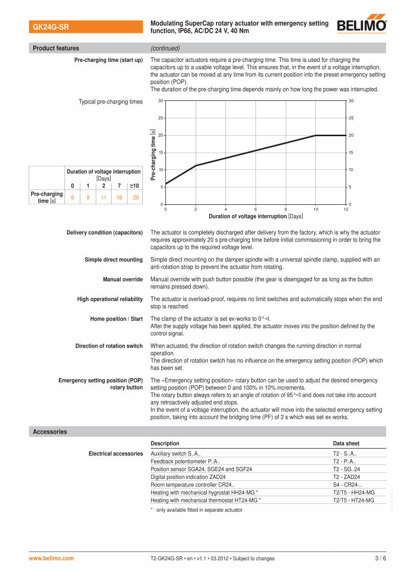
Pre-charging time (start up) The capacitor actuators require a pre-charging time. This time is used for charging the capacitors up to a usable voltage level. This ensures that, in the event of a voltage interruption, the actuator can be moved at any time from its current position into the preset emergency setting position (POP).The duration of the pre-charging time depends mainly on how long the power was interrupted.
Typical pre-charging times
0
0
5
10
15
20
25
30
0
5
10
15
20
25
30
2 4 6 8 10 12
Delivery condition (capacitors) The actuator is completely discharged after delivery from the factory, which is why the actuator requires approximately 20 s pre-charging time before initial commissioning in order to bring the capacitors up to the required voltage level.
Simple direct mounting Simple direct mounting on the damper spindle with a universal spindle clamp, supplied with an anti-rotation strap to prevent the actuator from rotating.
Manual override Manual override with push button possible (the gear is disengaged for as long as the button remains pressed down).
High operational reliability The actuator is overload-proof, requires no limit switches and automatically stops when the end stop is reached.
Home position / Start The clamp of the actuator is set ex-works to 0° .After the supply voltage has been applied, the actuator moves into the position defined by the control signal.
Direction of rotation switch When actuated, the direction of rotation switch changes the running direction in normal operation.The direction of rotation switch has no influence on the emergency setting position (POP) which has been set.
Emergency setting position (POP) rotary button
The «Emergency setting position» rotary button can be used to adjust the desired emergency setting position (POP) between 0 and 100% in 10% increments.The rotary button always refers to an angle of rotation of 95° and does not take into account any retroactively adjusted end stops.In the event of a voltage interruption, the actuator will move into the selected emergency setting position, taking into account the bridging time (PF) of 2 s which was set ex-works.
Pre-
char
ging
tim
e [ s
]
Duration of voltage interruption [Days]
Duration of voltage interruption[Days]
0 1 2 7 ≥10Pre-charging
time [s] 6 9 11 16 20
Accessories
Description Data sheet
Electrical accessories Auxiliary switch S..A.. T2 - S..A..Feedback potentiometer P..A.. T2 - P..A..Position sensor SGA24, SGE24 and SGF24 T2 - SG..24Digital position indication ZAD24 T2 - ZAD24Room temperature controller CR24.. S4 - CR24-..Heating with mechanical hygrostat HH24-MG * T2/T5 - HH24-MGHeating with mechanical thermostat HT24-MG * T2/T5 - HT24-MG
* only available fitted in separate actuator
. . . . . . . . . . . . . . . . . .
GK24G-SR Modulating SuperCap rotary actuator with emergency setting function, IP66, AC/DC 24 V, 40 Nm
4 / 6 T2-GK24G-SR • en • v1.1 • 03.2012 • Subject to changes www.belimo.com
Electrical installation
Wiring diagram
Y U
1 32 5
– +
T ~
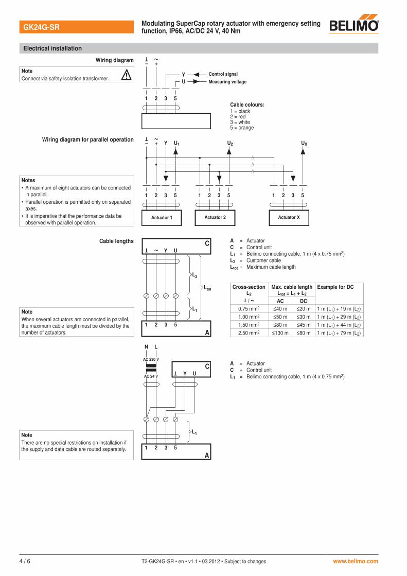
Cable colours:1 = black2 = red3 = white5 = orange
Wiring diagram for parallel operation
1 32 5
– +
T ~
Y U1
1 32 5
U2
1 32 5
UX
NoteConnect via safety isolation transformer. ! Control signal
Measuring voltage
Actuator 1 Actuator 2 Actuator X
Notes• A maximum of eight actuators can be connected
in parallel.• Parallel operation is permitted only on separated
axes.• It is imperative that the performance data be
observed with parallel operation.
Cable lengths
Y U
1 32 5T ~
A
C
L1
L2
Ltot
A = ActuatorC = Control unitL1 = Belimo connecting cable, 1 m (4 x 0.75 mm2)L2 = Customer cableLtot = Maximum cable length
Cross-sectionL2
T
/
~
Max. cable lengthLtot = L1 + L2
Example for DC
AC DC0.75 mm2 ≤40 m ≤20 m 1 m (L1) + 19 m (L2)1.00 mm2 ≤50 m ≤30 m 1 m (L1) + 29 m (L2)1.50 mm2 ≤80 m ≤45 m 1 m (L1) + 44 m (L2)2.50 mm2 ≤130 m ≤80 m 1 m (L1) + 79 m (L2)
NoteThere are no special restrictions on installation if the supply and data cable are routed separately.
LN
Y U
T
1 32 5
A
C
AC 24 V
AC 230 V
L1
A = ActuatorC = Control unitL1 = Belimo connecting cable, 1 m (4 x 0.75 mm2)
NoteWhen several actuators are connected in parallel, the maximum cable length must be divided by the number of actuators.
GK24G-SR Modulating SuperCap rotary actuator with emergency setting function, IP66, AC/DC 24 V, 40 Nm
www.belimo.com T2-GK24G-SR • en • v1.1 • 03.2012 • Subject to changes 5 / 6
. . . . . . . . . . . . . . . . . . . . . . . . . . . . . . . . . . . . . . . . . . . . . . . . . . . . . . . . . . . . . . . . . . . . . . . . . . . . . . . . . . . . . . . . . . . . . . . . . . . . . . . . . .
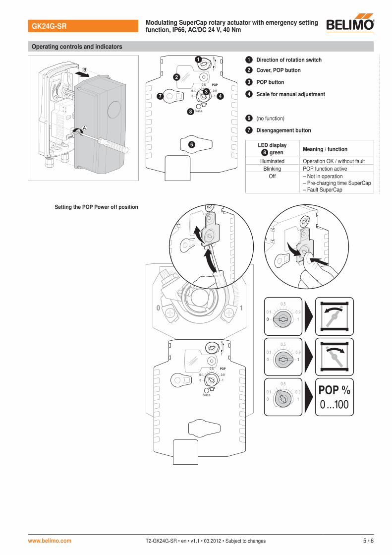
Operating controls and indicators
Status
100.1
0.5
1
0
0.9
POP
1 Direction of rotation switch
2 Cover, POP button
3 POP button
4 Scale for manual adjustment
6 (no function)
7 Disengagement button
LED displayMeaning / function8 green
Illuminated Operation OK / without fault Blinking POP function active
Off – Not in operation– Pre-charging time SuperCap– Fault SuperCap
Setting the POP Power off position
100.1
0.5
0.9
100.1
0.5
0.9
100.1
0.5
0.9 POP %0...100
Status
100.1
0.5
1
0
0.9
POP
10
6
7
1
2
34
8
A
B

GK24G-SR Modulating SuperCap rotary actuator with emergency setting function, IP66, AC/DC 24 V, 40 Nm
6 / 6 T2-GK24G-SR • en • v1.1 • 03.2012 • Subject to changes www.belimo.com
Dimensions [mm]
Dimensional drawings
86 238
16
32
01
9
~35
14 ... 22 mm 12 ... 18 mm
22 ... 26.7 mm 12 ... 18 mm 330
17
2
Damper spindle Length16 ... 75 14 ... 26.7 ≥12 ≤25.5
Related Documents


![IEC 60730-2-9{ed4.1) - Welcome to the IEC Webstoreed4.1}en.pdf · IEC 60730-2-9 edition 4.1 contains the fourth edition (2015-05) [documents 72/990/FDIS and 72/998/RVD] and its amendment](https://static.cupdf.com/doc/110x72/613c5c5e4c23507cb635553c/iec-60730-2-9ed41-welcome-to-the-iec-webstore-ed41enpdf-iec-60730-2-9.jpg)


