TM Freescale, the Freescale logo, AltiVec, C-5, CodeTEST, CodeWarrior, ColdFire, C-Ware, mobileGT, PowerQUICC, StarCore, and Symphony are trademarks of Freescale Semiconductor, Inc., Reg. U.S. Pat. & Tm. Off. BeeKit, BeeStack, CoreNet, the Energy Efficient Solutions logo, Flexis, MXC, Platform in a Package, Processor Expert, QorIQ, QUICC Engine, SMARTMOS, TurboLink and VortiQa are trademarks of Freescale Semiconductor, Inc. All other product or service names are the property of their respective owners. © 2010 Freescale Semiconductor, Inc. FTF-ENT-F0714 Industrial Safety starts with IEC/UL 60730 Standards June, 2010 Dugald Campbell - Large Appliance Systems Solutions Eng. Donnie Garcia - Industrial and Multi-Market Systems Engineer

Welcome message from author
This document is posted to help you gain knowledge. Please leave a comment to let me know what you think about it! Share it to your friends and learn new things together.
Transcript
TMFreescale, the Freescale logo, AltiVec, C-5, CodeTEST, CodeWarrior, ColdFire, C-Ware, mobileGT, PowerQUICC, StarCore, and Symphony are trademarks of Freescale Semiconductor, Inc., Reg. U.S. Pat. & Tm. Off. BeeKit, BeeStack, CoreNet, the Energy Efficient Solutions logo, Flexis, MXC, Platform in a Package, Processor Expert, QorIQ, QUICC Engine, SMARTMOS, TurboLink and VortiQa are trademarks of Freescale Semiconductor, Inc. All other product or service names are the property of their respective owners. © 2010 Freescale Semiconductor, Inc.
FTF-ENT-F0714
Industrial Safety starts with IEC/UL 60730 Standards
June, 2010
Dugald Campbell - Large Appliance Systems Solutions Eng.Donnie Garcia - Industrial and Multi-Market Systems Engineer

TMFreescale, the Freescale logo, AltiVec, C-5, CodeTEST, CodeWarrior, ColdFire, C-Ware, mobileGT, PowerQUICC, StarCore, and Symphony are trademarks of Freescale Semiconductor, Inc., Reg. U.S. Pat. & Tm. Off. BeeKit, BeeStack, CoreNet, the Energy Efficient Solutions logo, Flexis, MXC, Platform in a Package, Processor Expert, QorIQ, QUICC Engine, SMARTMOS, TurboLink and VortiQa are trademarks of Freescale Semiconductor, Inc. All other product or service names are the property of their respective owners. © 2010 Freescale Semiconductor, Inc. 3
Contents
►Introduce 60730 and how it applies to MCUs
►Classification Class B Class C►Components for Class B
• Component Table Matrix
►Popular Measures for Class B• Component Table• CPU Stuck at• Program Flow
Time Slot MonitoringInterruptsWatchdog Timeout Test
• Flash Memory• RAM memory• Communication
►Components for Class C• Component Table Matrix
►Popular Measures for Class C• Component Table Highlight CPU, RAM• CPU Instruction Test• RAM walking 1s Test
►Freescale’s Safety Offerings• Software for Class B• Software for Class C• Device hardware feature
►Summary

TMFreescale, the Freescale logo, AltiVec, C-5, CodeTEST, CodeWarrior, ColdFire, C-Ware, mobileGT, PowerQUICC, StarCore, and Symphony are trademarks of Freescale Semiconductor, Inc., Reg. U.S. Pat. & Tm. Off. BeeKit, BeeStack, CoreNet, the Energy Efficient Solutions logo, Flexis, MXC, Platform in a Package, Processor Expert, QorIQ, QUICC Engine, SMARTMOS, TurboLink and VortiQa are trademarks of Freescale Semiconductor, Inc. All other product or service names are the property of their respective owners. © 2010 Freescale Semiconductor, Inc. 4
What is IEC 60730?
►IEC 60730 – Automatic electrical controls for household and similar use – Part 1: General requirements
►Applies to Automatic Electrical Controls to perform safely within the household
►Discusses mechanical, electrical, electronic, environmental, endurance, EMC, abnormal operation of AC appliances
►Specifically for MCUs, Annex H: Requirements for Electronic Controls details new test and diagnostic methods to ensure the operation of embedded control hardware and software for appliances are safe

TMFreescale, the Freescale logo, AltiVec, C-5, CodeTEST, CodeWarrior, ColdFire, C-Ware, mobileGT, PowerQUICC, StarCore, and Symphony are trademarks of Freescale Semiconductor, Inc., Reg. U.S. Pat. & Tm. Off. BeeKit, BeeStack, CoreNet, the Energy Efficient Solutions logo, Flexis, MXC, Platform in a Package, Processor Expert, QorIQ, QUICC Engine, SMARTMOS, TurboLink and VortiQa are trademarks of Freescale Semiconductor, Inc. All other product or service names are the property of their respective owners. © 2010 Freescale Semiconductor, Inc. 5
IEC 60335-1 (IEC 60730-1)
► IEC 60335-1 Household and similar electrical appliances – Safety-Part 1 General Requirements
• Compliance safety requirements for Large Appliance Manufacturers
► IEC 60335-1 Annex R – Software Evaluation• Software shall be evaluated in accordance with the following clauses of Annex
H of IEC 60730-1, as modified below:
► IEC 60730-1 Annex H – Requirements for electronic controls• This chapter centers around Table H.11.12.7
► IEC 60730-1 Annex H Table H.11.12.7• Discusses the various embedded “components” that have to be tested to
comply for class B and class C electronic controls• Provides optional “measures” that are required to ensure reliable and safe
operation of the embedded “component”
Presenter
Presentation Notes
Be aware of other UL IEC specifications that will call apon IEC 60730. In Large Appliance there is 60335 which on Annex R _S/W evaluation …..calls apon Aneex H. Within Annex you call apon a Table H.11.12.7
TMFreescale, the Freescale logo, AltiVec, C-5, CodeTEST, CodeWarrior, ColdFire, C-Ware, mobileGT, PowerQUICC, StarCore, and Symphony are trademarks of Freescale Semiconductor, Inc., Reg. U.S. Pat. & Tm. Off. BeeKit, BeeStack, CoreNet, the Energy Efficient Solutions logo, Flexis, MXC, Platform in a Package, Processor Expert, QorIQ, QUICC Engine, SMARTMOS, TurboLink and VortiQa are trademarks of Freescale Semiconductor, Inc. All other product or service names are the property of their respective owners. © 2010 Freescale Semiconductor, Inc. 6
Table H.11.12.7 Annex H IEC 60730-1
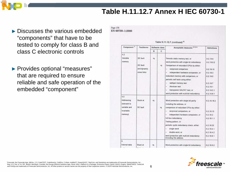
► Discusses the various embedded “components” that have to be tested to comply for class B and class C electronic controls
► Provides optional “measures” that are required to ensure reliable and safe operation of the embedded “component”
Presenter
Presentation Notes
Table H.11.12.7 details all components in an embedded system that are require some extra attention from a system designer to verify that it is functioning correctly. For each of the Components there is specific fault/error conditions that need to be checked depening on the classification. For each classification there are optional measures. Variable Memory for Class B needs to be checked for dc faults. Two optional measures are given For Class C we need to also chec for dynamic cross links, where there are 4 optional measures.

TMFreescale, the Freescale logo, AltiVec, C-5, CodeTEST, CodeWarrior, ColdFire, C-Ware, mobileGT, PowerQUICC, StarCore, and Symphony are trademarks of Freescale Semiconductor, Inc., Reg. U.S. Pat. & Tm. Off. BeeKit, BeeStack, CoreNet, the Energy Efficient Solutions logo, Flexis, MXC, Platform in a Package, Processor Expert, QorIQ, QUICC Engine, SMARTMOS, TurboLink and VortiQa are trademarks of Freescale Semiconductor, Inc. All other product or service names are the property of their respective owners. © 2010 Freescale Semiconductor, Inc. 7
IEC 60730 Classification of Appliances
►Class A are products with no feature/function that can harm a human being
►Class B• IEC 60730-1: Control functions intended to prevent unsafe operation of the
controlled equipment. Examples are: thermal cut-offs and door locks for laundry equipment
• IEC 60335-1: Software that includes code intended to prevent hazards if a fault, other than a software fault occurs in the appliance
►Class C• IEC 60730-1: Control functions which are intended to prevent special hazards
(e.g., explosion of the controlled equipment)Examples are automatic burner controls and thermal cut-outs for closed water heater systems (unvented)
• IEC 60335-1: Software that includes code intended to prevent hazards without the use of other protective devices
Presenter
Presentation Notes
The description of the classification for class B & C is not really well described, The description detailed in 60335 clarifies this a little better. Class B: Softwae that……. “ concludes that if there is a form of redundancy around the safety function then the system is class B Class C: “softwar that….” concludes that if there is no form of redundancy around the safety function then the system is class C Note: any system that has a special hazard such as gas appliance is deemed class C.

TMFreescale, the Freescale logo, AltiVec, C-5, CodeTEST, CodeWarrior, ColdFire, C-Ware, mobileGT, PowerQUICC, StarCore, and Symphony are trademarks of Freescale Semiconductor, Inc., Reg. U.S. Pat. & Tm. Off. BeeKit, BeeStack, CoreNet, the Energy Efficient Solutions logo, Flexis, MXC, Platform in a Package, Processor Expert, QorIQ, QUICC Engine, SMARTMOS, TurboLink and VortiQa are trademarks of Freescale Semiconductor, Inc. All other product or service names are the property of their respective owners. © 2010 Freescale Semiconductor, Inc. 8
Example Hazard: Overheating of Motor
Software only monitors motor currentIf function fails then hazard will occurNeed more thorough diagnostics to ensure thesoftware function is reliably working
Hardware PTC monitors temperature Software also monitors motor currentOne function fails the other ensuressafe operation
Class B – a fault occurring in a safety critical s/w routine will not result in a hazard due to another s/w routine or redundant h/w intervening.
HardwareFunction
Software Function
Class B
Software Function
Class CClass C – a fault occurring in a safety critical software routine will result in a hazard.
Presenter
Presentation Notes
The top motor control implementation shows the s/w function is monitoring the current flow via ADC, but additionally we have a PTC that provides the redundancy to make it class B. Thus if software routine has a fault and the motor current increases the PTC will eventually go open circuit. Similary if the PTC is not working the S/w ADC monitoring should react to the fault. The bottom solution there is only the software reading the ADC and the current, thus a fault in the software will cause the hazard. Thus Class C Classifying your system all functions that could be a hazard need to be examined . The majority of large appliances are deemed to be class B.

TMFreescale, the Freescale logo, AltiVec, C-5, CodeTEST, CodeWarrior, ColdFire, C-Ware, mobileGT, PowerQUICC, StarCore, and Symphony are trademarks of Freescale Semiconductor, Inc., Reg. U.S. Pat. & Tm. Off. BeeKit, BeeStack, CoreNet, the Energy Efficient Solutions logo, Flexis, MXC, Platform in a Package, Processor Expert, QorIQ, QUICC Engine, SMARTMOS, TurboLink and VortiQa are trademarks of Freescale Semiconductor, Inc. All other product or service names are the property of their respective owners. © 2010 Freescale Semiconductor, Inc.
Industrial Safety Starts with Silicon:Class B

TMFreescale, the Freescale logo, AltiVec, C-5, CodeTEST, CodeWarrior, ColdFire, C-Ware, mobileGT, PowerQUICC, StarCore, and Symphony are trademarks of Freescale Semiconductor, Inc., Reg. U.S. Pat. & Tm. Off. BeeKit, BeeStack, CoreNet, the Energy Efficient Solutions logo, Flexis, MXC, Platform in a Package, Processor Expert, QorIQ, QUICC Engine, SMARTMOS, TurboLink and VortiQa are trademarks of Freescale Semiconductor, Inc. All other product or service names are the property of their respective owners. © 2010 Freescale Semiconductor, Inc. 10
60730 Class B Components
Appliance Manufacturers are required to implement “measures” to ensure thatthe above components are reliably working
Presenter
Presentation Notes
For Class B manufacturers need to assess 14 components as stated here. Each component is tested for a particular fault.error and 60730 provides optional measures to test these components. We will now examine Each component in detail in what optional measures are provided which measure is most cost effective to deploy on a single chip MCU based system.

TMFreescale, the Freescale logo, AltiVec, C-5, CodeTEST, CodeWarrior, ColdFire, C-Ware, mobileGT, PowerQUICC, StarCore, and Symphony are trademarks of Freescale Semiconductor, Inc., Reg. U.S. Pat. & Tm. Off. BeeKit, BeeStack, CoreNet, the Energy Efficient Solutions logo, Flexis, MXC, Platform in a Package, Processor Expert, QorIQ, QUICC Engine, SMARTMOS, TurboLink and VortiQa are trademarks of Freescale Semiconductor, Inc. All other product or service names are the property of their respective owners. © 2010 Freescale Semiconductor, Inc. 11
IEC 60730 CLASS B
Reg
iste
rs S
tuck
at:
Pro
gram
Cou
nter
stu
ck a
t
Inte
rrupt
han
dlin
g an
d ex
ecut
ion
cloc
k
Inva
raib
le M
emor
y
Var
aibl
e m
emor
y
addr
essi
ng S
tuck
at
Inte
rnal
dat
a pa
th S
tuck
at
Add
ress
ing
Wro
ng a
ddre
ss
Ham
min
g D
ista
nce
3
Tim
ing
Wro
ng s
eque
nce
Inpu
t/Out
put P
erip
hery
Acceptable measures DefininitionsComparison of redundant CPUs be either
reciprocal comparison, H.2.18.15 X Xindependent hardware comparator, H.2.18.3 X Xfull bus redundancy. H.2.18.1.1 X
Word protection with single bit redundancy H.2.19.8.2 X X X X X X XWord protection with multi-bit redundancy including address H.2.19.8.1 X X
Frequency monitoring H.2.18.10.1 XTime-slot and logical monitoring, H.2.18.10.3 XIndependent time-slot monitoring or H.2.18.10.4 X X X X XLogical monitoring of the program sequence. H.2.18.10.2 X XTransfer redundancy H.2.18.2.2 XProtocol test H.2.18.14 Scheduled transmission. H.2.18.18 X X
Periodic self-test H.2.16.6 Static memory test H.2.19.6 X X X
Periodic modified checksum; H.2.19.3.1 XMultiple checksum, H.2.19.3.2 XPeriodic CRC-single word, H.2.19.4.1 X X XPeriodic CRC double word H.2.19.4.2 X Xtesting pattern H.2.18.22 X X X
Functional test H.2.16.5 X X XPlausibility check H.2.18.13 X
Class B Test Matrix
Pre-application code
PeriodicSelf checks
Indep. WDOG
S/W Design
ECC type
Dual MCU/CPU
Com
pone
nts
Presenter
Presentation Notes
Before looking at each component the matrix shown shows that the manufacturers has various options in how to fulfill class B certification. Green line uses optional measures around periodic software tests and pre-application code approaches. This is more costly in the development phase compared to the gray line approach which uses additional hardware instead of periodic s/w tests. Many ways to crack the 60730 nut.

TMFreescale, the Freescale logo, AltiVec, C-5, CodeTEST, CodeWarrior, ColdFire, C-Ware, mobileGT, PowerQUICC, StarCore, and Symphony are trademarks of Freescale Semiconductor, Inc., Reg. U.S. Pat. & Tm. Off. BeeKit, BeeStack, CoreNet, the Energy Efficient Solutions logo, Flexis, MXC, Platform in a Package, Processor Expert, QorIQ, QUICC Engine, SMARTMOS, TurboLink and VortiQa are trademarks of Freescale Semiconductor, Inc. All other product or service names are the property of their respective owners. © 2010 Freescale Semiconductor, Inc. 12
CPU Registers “Stuck At”
► Functional test H.2.16.5 - A single channel structure in which test data is introduced to the functional unit prior to its operation
► Periodic self-test H.2.16.6 - A single channel structure in which components of the control are periodically tested during operation using either:
Static memory test H.2.19.6 - a fault/error control technique which is intended to detect only static errorsWord protection with single bit redundancy H.2.19.8.2 - a fault/error control technique in which a single bit is added to each word in the memory area under test and saved, creating either even or odd parity. As each word is read, a parity check is conducted.
Using #0x55 and #0xAA dataCheck each CPU register for “stuck at”
Presenter
Presentation Notes
3 Possible measures to test component CPU Registers stuck at. Ie that no bits in CPU registers are stuck at a 1 or 0. Functional Test: This is a pre-operatio test where data is supplied to the “CPU registers” and expected responses are monitored. If an un-expected response is returned then CPU register are seen as faulty. Display to user fault/seek engineer. Periodic Self test: Word protection with single bit redundancy requires additional hardware to monitor the CPU, and additional memory to store the parity of each memory location. This type of circuit adds significant cost to a MCU product which does not make it first choice for an appliance manufacturer. The alternative of utilizing functional tests prior to shipment or in-line periodic self-tests that cost less to implement, are seen as more favourable measures for appliance manufacturers. Static memory test is simpler and more cost effective to implement. The MC9S08AW60 MCU utilizes the 8-bit HCS08 CPU. The HCS08 CPU consists of an 8-bit Accumulator, a 16-bit Index Register H:X , a 16-bit Stack Pointer, a 16-bit Program Counter PC and a 6-bit Condition Code Register CCR. With the von-Neuman architecture of the HCS08 CPU it is very easy to implement small routines to test the CPU registers for “stuck at” faults. Example assembly routines are provided below. These small routines can be called on power-up and periodically taking a few 10s of uSecs to execute, will clarify the CPU registers are not stuck.

TMFreescale, the Freescale logo, AltiVec, C-5, CodeTEST, CodeWarrior, ColdFire, C-Ware, mobileGT, PowerQUICC, StarCore, and Symphony are trademarks of Freescale Semiconductor, Inc., Reg. U.S. Pat. & Tm. Off. BeeKit, BeeStack, CoreNet, the Energy Efficient Solutions logo, Flexis, MXC, Platform in a Package, Processor Expert, QorIQ, QUICC Engine, SMARTMOS, TurboLink and VortiQa are trademarks of Freescale Semiconductor, Inc. All other product or service names are the property of their respective owners. © 2010 Freescale Semiconductor, Inc. 13
► The measure: Time-slot monitoring or H.2.18.10.4 – a fault/error control technique in which timing devices with an independent time base are periodically triggered in order to monitor the program function and sequence. An example is a watchdog timer.
► Covers checking and verifying of the following components:• CPU Program Counter, Interrupt Handling, Clock, External Communications &Timing
CPU Program Counter, Interrupt Handling, Clock, External Communications and Timing
Appl code Appl code Appl code Appl code Appl code
Time-slot monitoring; a periodic check on program code flow
CPU Access
Periodic interrupt
Program flow check Program flow check
A Periodic Interrupt e.g., timer overflow interrupts the application periodicallyand within the ISR some checks are made.
Presenter
Presentation Notes
Time Slot monitoring is a key “measure” that verifies the operation of several components in class B, namely CPU Program Counter Interrupt Handling, Clock (CPU clock) External communications And Timing of communications. Time-slot monitoring or H.2.18.10.4 – a fault/error control technique in which timing devices with an independent time base are periodically triggered in order to monitor the programme function and sequence. An example is a watchdog timer. In real terms this means that the system developer must interrupt the application code periodically and analyse if the program flow is working as expected and intended. A Periodic Interrupt eg. timer overflow interrupts the application periodically And within the ISR some checks are made.

TMFreescale, the Freescale logo, AltiVec, C-5, CodeTEST, CodeWarrior, ColdFire, C-Ware, mobileGT, PowerQUICC, StarCore, and Symphony are trademarks of Freescale Semiconductor, Inc., Reg. U.S. Pat. & Tm. Off. BeeKit, BeeStack, CoreNet, the Energy Efficient Solutions logo, Flexis, MXC, Platform in a Package, Processor Expert, QorIQ, QUICC Engine, SMARTMOS, TurboLink and VortiQa are trademarks of Freescale Semiconductor, Inc. All other product or service names are the property of their respective owners. © 2010 Freescale Semiconductor, Inc. 14
Time Slot Monitoring
►Watchdogs should and must be deployed as the backup if all other safety mechanisms fail and/or there is code runaway
►Not really designed for periodic interrupts to execute time slot monitoring►A better feature is an “independent clock” timer module e.g., S08AC60 RTI
Block diagram of Freescale MC9S08AC60 microcontroller
rese
tTime-slot monitoring
If all other mechanismsfail or code runaway
Presenter
Presentation Notes
Although 60730 recommends a watchdog for timeslot monitoring, this is probaly not the best choice. Watchdogs should & must be deployed as the backup if all other safety mechanisms fail and/or there is code runaway. Not really designed for periodic interrupts to execuet time slot monitoring. A better feature is an “independently clock” timer module eg S08AC60 RTI. The S08AC60’s rti Real Time Interrupt function is basically a small counter that is clocked by an internal RC oscillator and interrupts the CPU periodically. The period is programmable in software and interrupt periods are 8ms/32ms/64ms/128/256/512ms and ~1 sec. Having a watchdog counter sourced from an independent clock ensures that if the CPU clock was to somehow stop, then no code will be executed, and thus no interrupts would be serviced, and if halted in a possible hazard condition, the wdog will still timeout and reset the MCU’s peripherals to a known safe state.
TMFreescale, the Freescale logo, AltiVec, C-5, CodeTEST, CodeWarrior, ColdFire, C-Ware, mobileGT, PowerQUICC, StarCore, and Symphony are trademarks of Freescale Semiconductor, Inc., Reg. U.S. Pat. & Tm. Off. BeeKit, BeeStack, CoreNet, the Energy Efficient Solutions logo, Flexis, MXC, Platform in a Package, Processor Expert, QorIQ, QUICC Engine, SMARTMOS, TurboLink and VortiQa are trademarks of Freescale Semiconductor, Inc. All other product or service names are the property of their respective owners. © 2010 Freescale Semiconductor, Inc. 15
Token Passing – Program Flow
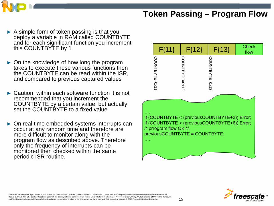
► A simple form of token passing is that you deploy a variable in RAM called COUNTBYTE and for each significant function you increment this COUNTBYTE by 1
► On the knowledge of how long the program takes to execute these various functions then the COUNTBYTE can be read within the ISR, and compared to previous captured values
► Caution: within each software function it is not recommended that you increment the COUNTBYTE by a certain value, but actually set the COUNTBYTE to a fixed value
► On real time embedded systems interrupts can occur at any random time and therefore are more difficult to monitor along with the program flow as described above. Therefore only the frequency of interrupts can be monitored then checked within the same periodic ISR routine.
F{11} F{12} F{13} Checkflow
….If (COUNTBYTE < (previousCOUNTBYTE+2)) Error;If (COUNTBYTE > (previousCOUNTBYTE+6)) Error;/* prrogram flow OK */previousCOUNTBYTE = COUNTBYTE;…..
CO
UN
TBY
TE=0x11;
CO
UN
TBY
TE=0x12;
CO
UN
TBY
TE=0x13;
Presenter
Presentation Notes
Within this Periodic interrupt a check on the Program Flow can be initiated by using Token Passing. A simple form of token passing is that you deploy a variable in RAM called COUNTBYTE and for each significant function you increment this COUNTBYTE by 1. On the knowledge of how long the program takes to execute these various functions then the COUNTBYTE can be read within the ISR, and compared to previous captured value and if within a certain range will deem the program flow to be running as expected. If outwith this range then program is performing not as expected and mechanisms to reset or place the MCU in a safe mode can be made. Caution: within each software function it is not recommended that you increment the COUNTBYTE by a certain value, but actually set the COUNTBYTE to a fixed value. On real time embedded systems interrupts can occur at any random time and therefore are more difficult to monitor along with the program flow as described above. Therefore only the frequency of interrupts can be monitored then checked within the same periodic ISR routine.

TMFreescale, the Freescale logo, AltiVec, C-5, CodeTEST, CodeWarrior, ColdFire, C-Ware, mobileGT, PowerQUICC, StarCore, and Symphony are trademarks of Freescale Semiconductor, Inc., Reg. U.S. Pat. & Tm. Off. BeeKit, BeeStack, CoreNet, the Energy Efficient Solutions logo, Flexis, MXC, Platform in a Package, Processor Expert, QorIQ, QUICC Engine, SMARTMOS, TurboLink and VortiQa are trademarks of Freescale Semiconductor, Inc. All other product or service names are the property of their respective owners. © 2010 Freescale Semiconductor, Inc. 16
Token Passing on interrupts
RTI ISRINC “RTI_count”
Had 2-3 SCI ints?
Clear “SCI_count”
RTI==%16 ?
Received > 1 Timer1 int ?
Clear “Timer1_count”
RTI==300?
Received =>1 TCAP2 int ?
Clear “TCAP2_count”Clear “RTI_count”
Y
N
N
N
N
N
Y
Y
Y
Y
INC “SCI_count”
SCI ISR
RTI
RTI
INC “TCAP2_count”
TCAP2 ISR
RTI
INC “tmr1_count”
Tmr1 ISR
RTI
Presenter
Presentation Notes
Each interrupt function can deploy a “count” byte that is incremented within each of the corresponding ISR routines. Using the 9S08AW60s RTI function code can be created to verify the number of interrupts that have occurred and decide if the control system is executing in the correct manner. e.g. if the RTI is set to interrupt every 8mS then it may expect to see 2-3 SCI interrupts within this time period, and 1 Timer overflow interrupt every 16 RTIs, a Timer Capture interrupt every 300 RTIs. Code can be written to track and compare the number of RTIs with the the number of occurrences of other interrupts.

TMFreescale, the Freescale logo, AltiVec, C-5, CodeTEST, CodeWarrior, ColdFire, C-Ware, mobileGT, PowerQUICC, StarCore, and Symphony are trademarks of Freescale Semiconductor, Inc., Reg. U.S. Pat. & Tm. Off. BeeKit, BeeStack, CoreNet, the Energy Efficient Solutions logo, Flexis, MXC, Platform in a Package, Processor Expert, QorIQ, QUICC Engine, SMARTMOS, TurboLink and VortiQa are trademarks of Freescale Semiconductor, Inc. All other product or service names are the property of their respective owners. © 2010 Freescale Semiconductor, Inc. 17
Independent Clocked Watchdog
► S08AC60 Watchdog using 1Khz RC oscillator is independent of CPU clock source
► Providing reliable protection against Clock faults (too fast/slow, stuck clock) and code runaway
► Watchdog must provide an asynchronous reset to all peripherals and input/output ports
► A timeout test should be initiated after power on reset, prior to running application code
MCG
#1kHzRCosc
reset
“Write Once” after reset bits
Refresh is a Write toSystem Reset Register (SRS) $1800
COP SRS
COPCLKSCOPT
COPE
5 10 15
5 10
218
213
528
5
25
MCGOUT
Reset to 1 (long)
Reset to 1 (MCG)
Reset to 1 (enabled)
MCG
#1kHzRCosc
reset
“Write Once” after reset bits
Refresh is a Write toSystem Reset Register (SRS) $1800
COP SRS
COPCLKSCOPT
COPE
5 10 155 10 15
5 105 10
218
213
528
528
5
25
5
25
MCGOUT
Reset to 1 (long)
Reset to 1 (MCG)
Reset to 1 (enabled)
Presenter
Presentation Notes
To Re-cap on Watchdogs They must have an independent clock source from CPU allowing the wdog to recover from a stuck CPU clock. They must force a reset and not an interrupt, remember that an interrupt will not recover if a stuck CPU clock. And most importantly prior to application code execution the watchdog should be tested first to ensure the independent clock, and timeout is as expected, and also ensure that it does reset the MCU as intended.
TMFreescale, the Freescale logo, AltiVec, C-5, CodeTEST, CodeWarrior, ColdFire, C-Ware, mobileGT, PowerQUICC, StarCore, and Symphony are trademarks of Freescale Semiconductor, Inc., Reg. U.S. Pat. & Tm. Off. BeeKit, BeeStack, CoreNet, the Energy Efficient Solutions logo, Flexis, MXC, Platform in a Package, Processor Expert, QorIQ, QUICC Engine, SMARTMOS, TurboLink and VortiQa are trademarks of Freescale Semiconductor, Inc. All other product or service names are the property of their respective owners. © 2010 Freescale Semiconductor, Inc. 18
Watchdog Timeout and Reset Test
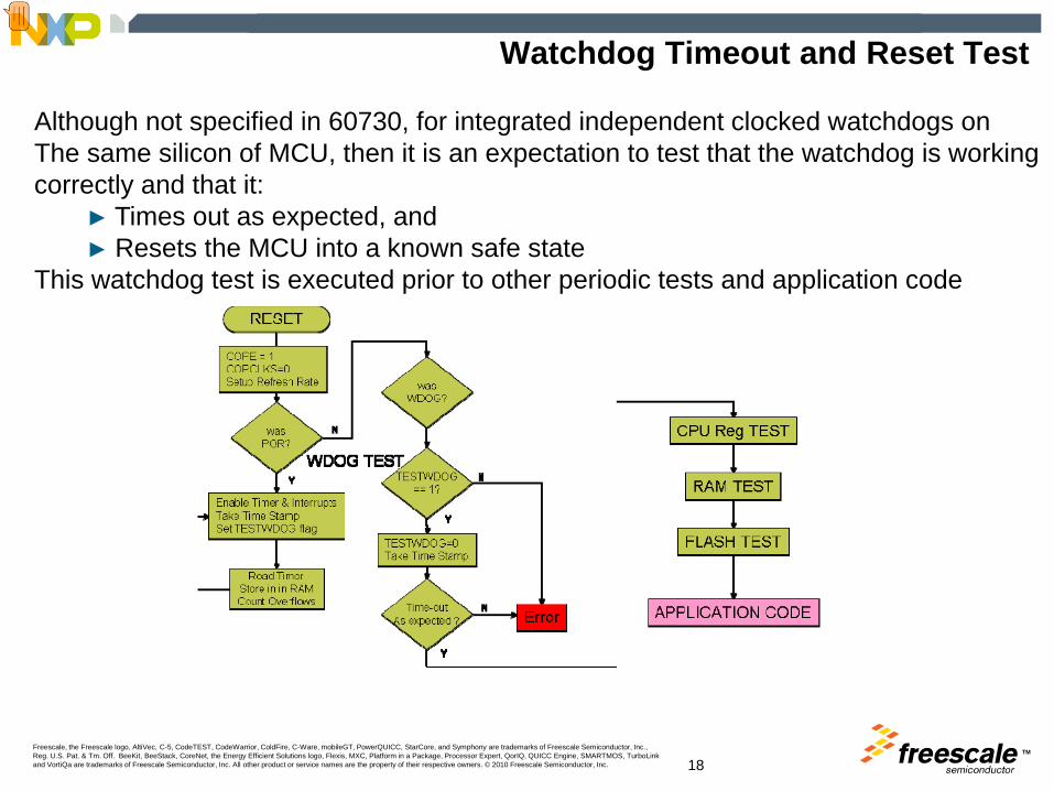
Although not specified in 60730, for integrated independent clocked watchdogs on The same silicon of MCU, then it is an expectation to test that the watchdog is working correctly and that it:
► Times out as expected, and► Resets the MCU into a known safe state
This watchdog test is executed prior to other periodic tests and application code
Presenter
Presentation Notes
The RESET routine should interrogate the System Reset Status Register to identify the cause. If a POR is the cause, then s/w should take a time stamp reading from a Timer running from the CPU clock source. Then wait in a loop of “do nothing” to force the WDOG to timeout. The interrogation of the SRSR should indicate a COP reset and then another time-stamp should be taken, this evaluated with the previous time stamp should be within an expected boundary to indicate the 1kHz source is correct. Note the use of a TESTWDOG bit to indicate this is the WDOG TIMEOUT test and not a failure condition.
TMFreescale, the Freescale logo, AltiVec, C-5, CodeTEST, CodeWarrior, ColdFire, C-Ware, mobileGT, PowerQUICC, StarCore, and Symphony are trademarks of Freescale Semiconductor, Inc., Reg. U.S. Pat. & Tm. Off. BeeKit, BeeStack, CoreNet, the Energy Efficient Solutions logo, Flexis, MXC, Platform in a Package, Processor Expert, QorIQ, QUICC Engine, SMARTMOS, TurboLink and VortiQa are trademarks of Freescale Semiconductor, Inc. All other product or service names are the property of their respective owners. © 2010 Freescale Semiconductor, Inc. 19
Invariable Memory (Flash) – All Single Bits Faults
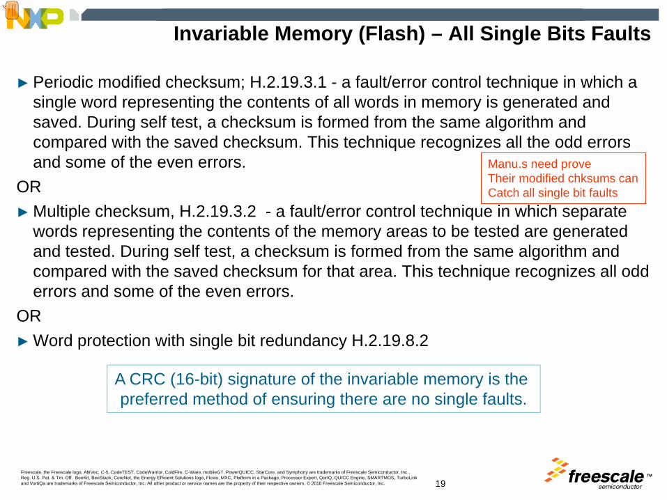
► Periodic modified checksum; H.2.19.3.1 - a fault/error control technique in which a single word representing the contents of all words in memory is generated and saved. During self test, a checksum is formed from the same algorithm and compared with the saved checksum. This technique recognizes all the odd errors and some of the even errors.
OR► Multiple checksum, H.2.19.3.2 - a fault/error control technique in which separate
words representing the contents of the memory areas to be tested are generated and tested. During self test, a checksum is formed from the same algorithm and compared with the saved checksum for that area. This technique recognizes all odd errors and some of the even errors.
OR ► Word protection with single bit redundancy H.2.19.8.2
A CRC (16-bit) signature of the invariable memory is the preferred method of ensuring there are no single faults.
Manu.s need proveTheir modified chksums canCatch all single bit faults
Presenter
Presentation Notes
Invariable memory is generally seen as the program memory using either NVM technology such as EEPROM, EPROM, or FLASH and masked ROM. 3 optional measures to verify that the invariable memory has no single bit faults are: The main issue here is that there is no recommended “modified checksum” approach and a manufacturer will need to develop an algorithm and quantify its reliable enough to recognise single bit faults in a particilar memory array. For this reason, most manufacturers have deployed a CRC check which is deemed stringent enough for class C systems, but as it is well understood and recognised approach, and is easily implemented in software as well as hardware.
TMFreescale, the Freescale logo, AltiVec, C-5, CodeTEST, CodeWarrior, ColdFire, C-Ware, mobileGT, PowerQUICC, StarCore, and Symphony are trademarks of Freescale Semiconductor, Inc., Reg. U.S. Pat. & Tm. Off. BeeKit, BeeStack, CoreNet, the Energy Efficient Solutions logo, Flexis, MXC, Platform in a Package, Processor Expert, QorIQ, QUICC Engine, SMARTMOS, TurboLink and VortiQa are trademarks of Freescale Semiconductor, Inc. All other product or service names are the property of their respective owners. © 2010 Freescale Semiconductor, Inc. 20
Flash CRC Test
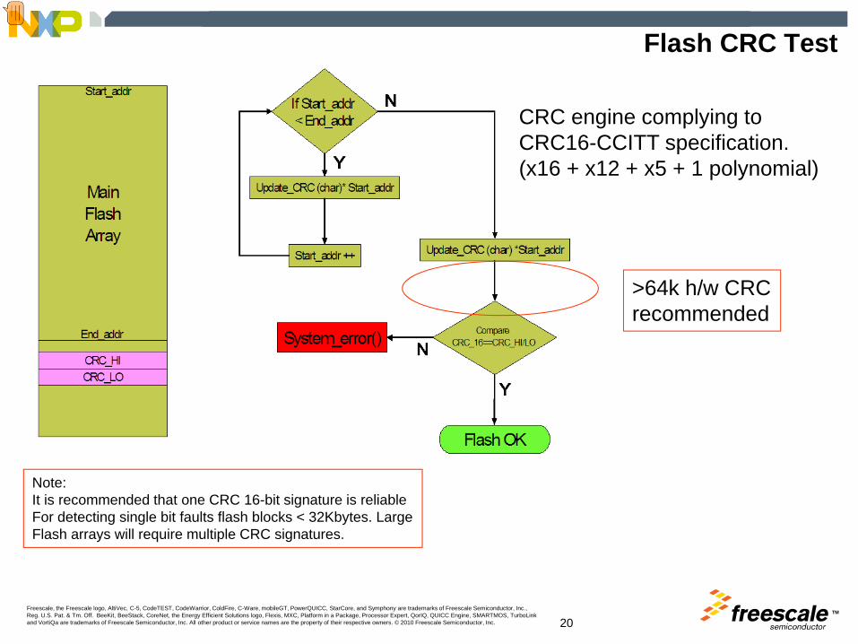
CRC engine complying toCRC16-CCITT specification. (x16 + x12 + x5 + 1 polynomial)
Note: It is recommended that one CRC 16-bit signature is reliableFor detecting single bit faults flash blocks < 32Kbytes. LargeFlash arrays will require multiple CRC signatures.
>64k h/w CRCrecommended
Presenter
Presentation Notes
Implementing a CRC signature requires the developer to assign memory space to store the golden signature. The goldone signature is calculated prior to production release on all the application code and stored in another flash location. Then in real time application at periodic times a rouytine is called to re-calculate the CRC for the flash array. Once completed the result is compared to the golden signature and if equal then continue with appliaction, if not then it would indicate a bit change in the flash and therefore the application should be placed into a safe condition. A commonly used 16bit CRC is the CRC16-CITT which uses the polynominal. This is publically available and there are example C code of the adding bytes to the algorithm . that can be easily cut pasted into application code For memory arrays > 64K it is recommended to utilise a H/W CRC engine to help reduce the execution time. Also for arrays larger than 48K bytes, the array should be segmented and tested with multiple 16bit signatures.

TMFreescale, the Freescale logo, AltiVec, C-5, CodeTEST, CodeWarrior, ColdFire, C-Ware, mobileGT, PowerQUICC, StarCore, and Symphony are trademarks of Freescale Semiconductor, Inc., Reg. U.S. Pat. & Tm. Off. BeeKit, BeeStack, CoreNet, the Energy Efficient Solutions logo, Flexis, MXC, Platform in a Package, Processor Expert, QorIQ, QUICC Engine, SMARTMOS, TurboLink and VortiQa are trademarks of Freescale Semiconductor, Inc. All other product or service names are the property of their respective owners. © 2010 Freescale Semiconductor, Inc. 21
Flash CRC Test – Hardware Implementation
CRC engine complying toCRC16-CCITT specification. (x16 + x12 + x5 + 1 polynomial).
One byte shifted through CRC in 1 CPU cycle
Deployed on HCS08ACxx and MCF51ACxx, devices
Can be used for Flash, RAM andcommunication transfers
Seed by writing to CRCH, then CRCLUpdate via CRCL onlyA read of both CRCH and CRCL provides the current CRC signature
Presenter
Presentation Notes
This is an example of a hardware CRC engine that is deployed on Freescales HCS08AC and 51AC family of microcontrollers. It take 1 CPU clock cycle to update the engine by 1 byte, compared to ~700 clock cycles for a s/w version on an 8-bit S08. 15 times faster. Also this type of CRC is easier to implement on top of communication protocols, or small pieces of RAM which change infrequently, or critical registers.

TMFreescale, the Freescale logo, AltiVec, C-5, CodeTEST, CodeWarrior, ColdFire, C-Ware, mobileGT, PowerQUICC, StarCore, and Symphony are trademarks of Freescale Semiconductor, Inc., Reg. U.S. Pat. & Tm. Off. BeeKit, BeeStack, CoreNet, the Energy Efficient Solutions logo, Flexis, MXC, Platform in a Package, Processor Expert, QorIQ, QUICC Engine, SMARTMOS, TurboLink and VortiQa are trademarks of Freescale Semiconductor, Inc. All other product or service names are the property of their respective owners. © 2010 Freescale Semiconductor, Inc. 22
Variable Memory – DC Fault► Periodic static memory test H.2.19.6 - a fault/error control
technique which is intended to detect only static errorsor► Word protection with single bit redundancy H.2.19.8.2 -
(hardware error code correction)
March C (van der Goor, 1991)
Presenter
Presentation Notes
Variable memory is generally seen as the data memory normally implemented in volatile RAM . Two optional measures to verify that the invariable memory has no single bit faults are Periodic static memory test H.2.19.6 or Word protection with single bit redundancy H.2.19.8.2 A periodic static memory test can be developed in software (assembler will help reduce code size and execution time) to clear all RAM to $00, verify, set all RAM to $FF, verify and a checkerboard of $AA, verify, $55 & verify. This routine will test for any static errors within the RAM. �There are many periodic static memory algorithms for checking for DC faults. One commonly used algorithm is the March C( van de Goor,1991). This algorithm is shown here. STEP 1 write all zeros to the array. STEP2 Read Zeros, Write 1s incrementing through the array. STEP3 Read 1s write 0s incrementing thro array STEP4 Read 0s writ 1s decrementing thro array STEP5 Read 1s write0s decrementing thro array. STEP 6 Read and confirm all zeros. This algorithm takes a considerable amount of execution time for RAM arrays of >4Kbytes To save execution time there exists a March X pattern that misses Step3& 4 but is deemed robust enough to catch all DC faults that the March C pattern can uncover.
TMFreescale, the Freescale logo, AltiVec, C-5, CodeTEST, CodeWarrior, ColdFire, C-Ware, mobileGT, PowerQUICC, StarCore, and Symphony are trademarks of Freescale Semiconductor, Inc., Reg. U.S. Pat. & Tm. Off. BeeKit, BeeStack, CoreNet, the Energy Efficient Solutions logo, Flexis, MXC, Platform in a Package, Processor Expert, QorIQ, QUICC Engine, SMARTMOS, TurboLink and VortiQa are trademarks of Freescale Semiconductor, Inc. All other product or service names are the property of their respective owners. © 2010 Freescale Semiconductor, Inc. 23
March X Pattern
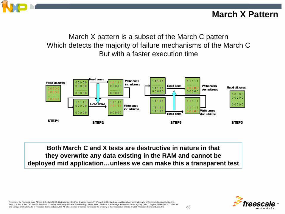
March X pattern is a subset of the March C patternWhich detects the majority of failure mechanisms of the March C
But with a faster execution time
Both March C and X tests are destructive in nature in thatthey overwrite any data existing in the RAM and cannot be
deployed mid application…unless we can make this a transparent test
Presenter
Presentation Notes
Both March X and March C test patterns are destructive in nature, in that all RAM contents are written to therefore this algorithm can be executed at power on or reset and not in-application. There is a method to make this RAM test “transparent” and more usable in application, by separating the RAM into smaller manageable segments.
TMFreescale, the Freescale logo, AltiVec, C-5, CodeTEST, CodeWarrior, ColdFire, C-Ware, mobileGT, PowerQUICC, StarCore, and Symphony are trademarks of Freescale Semiconductor, Inc., Reg. U.S. Pat. & Tm. Off. BeeKit, BeeStack, CoreNet, the Energy Efficient Solutions logo, Flexis, MXC, Platform in a Package, Processor Expert, QorIQ, QUICC Engine, SMARTMOS, TurboLink and VortiQa are trademarks of Freescale Semiconductor, Inc. All other product or service names are the property of their respective owners. © 2010 Freescale Semiconductor, Inc. 24
Transparent March
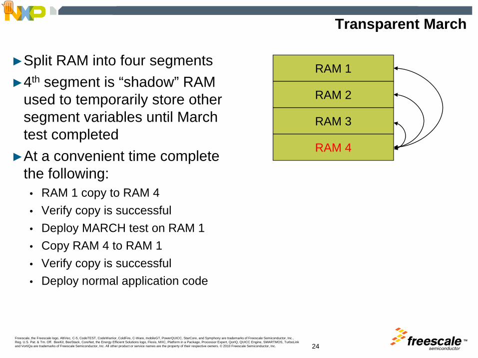
►Split RAM into four segments►4th segment is “shadow” RAM
used to temporarily store other segment variables until March test completed
►At a convenient time complete the following:
• RAM 1 copy to RAM 4• Verify copy is successful• Deploy MARCH test on RAM 1• Copy RAM 4 to RAM 1• Verify copy is successful• Deploy normal application code
RAM 1
RAM 2
RAM 3
RAM 4
Presenter
Presentation Notes
For example this RAM array is split into 4 segments of equal size. Segment 4 is a redundant segment and not used for the application code. Thus at a convenient times in the application code the application can be paused for example and one of the 3 segments is tested. The process for testing RAM 1 is firstly copy contents to RAM 3, verify that copy si successful, deploy MARCH test in RAM1. If it passes the March test, copy RAM4 to RAM1, verify copy is successful. Then continue with application code.

TMFreescale, the Freescale logo, AltiVec, C-5, CodeTEST, CodeWarrior, ColdFire, C-Ware, mobileGT, PowerQUICC, StarCore, and Symphony are trademarks of Freescale Semiconductor, Inc., Reg. U.S. Pat. & Tm. Off. BeeKit, BeeStack, CoreNet, the Energy Efficient Solutions logo, Flexis, MXC, Platform in a Package, Processor Expert, QorIQ, QUICC Engine, SMARTMOS, TurboLink and VortiQa are trademarks of Freescale Semiconductor, Inc. All other product or service names are the property of their respective owners. © 2010 Freescale Semiconductor, Inc. 25
Making a “Destructive” into “Transparent”
RAM 1
RAM 2
RAM 3
RAM 4
Copy RAM1 to RAM4.Verify data copied
MARCH X
RAM 2
RAM 3
RAM 1
March X on RAM1
RAM 1
RAM 2
RAM 3
RAM 1
Copy RAM4 to RAM1.Verify data copied
RAM 1
RAM 2
RAM 3
RAM 1
Copy RAM2 to RAM4.Verify data copied
RAM 1
RAM 2
RAM 3
MARCH X
March X on RAM4
RAM 1
MARCH X
RAM 3
RAM 2
March X on RAM2
RAM 1
RAM 2
RAM 3
RAM 4
Segment RAM
Redundant RAM segment
Presenter
Presentation Notes
Before executing test on application RAM the redundant RAM4 segment should also be tested initially. Although arguably on the first copy of another segment if there is an issue then the RAM verify would fail. The size of the RAM segments will vary depending on the application, and if the application can only be paused for a few mSecs at a time this will drive smaller RAM segments to be tested in a round robin fashion.

TMFreescale, the Freescale logo, AltiVec, C-5, CodeTEST, CodeWarrior, ColdFire, C-Ware, mobileGT, PowerQUICC, StarCore, and Symphony are trademarks of Freescale Semiconductor, Inc., Reg. U.S. Pat. & Tm. Off. BeeKit, BeeStack, CoreNet, the Energy Efficient Solutions logo, Flexis, MXC, Platform in a Package, Processor Expert, QorIQ, QUICC Engine, SMARTMOS, TurboLink and VortiQa are trademarks of Freescale Semiconductor, Inc. All other product or service names are the property of their respective owners. © 2010 Freescale Semiconductor, Inc. 26
Class B Memory Address and Data Path
►4.3 Addressing (relevant to variable and invariable memory) stuck at►5. Internal data path stuck at►5.2 Addressing - Wrong address
These components intended for external memory microprocessorbased designs. These components are tested by other measures
on single chip microcontrollers.
Presenter
Presentation Notes
These 3 components are intended for Microprocessor systems where there is an external address and data bus that is accessing both memory and peripherals. For embedded MCUs , microcontrollers, the addressing and data path are tested out with the memory tests CRC Flash Test and RAM March Tests.
TMFreescale, the Freescale logo, AltiVec, C-5, CodeTEST, CodeWarrior, ColdFire, C-Ware, mobileGT, PowerQUICC, StarCore, and Symphony are trademarks of Freescale Semiconductor, Inc., Reg. U.S. Pat. & Tm. Off. BeeKit, BeeStack, CoreNet, the Energy Efficient Solutions logo, Flexis, MXC, Platform in a Package, Processor Expert, QorIQ, QUICC Engine, SMARTMOS, TurboLink and VortiQa are trademarks of Freescale Semiconductor, Inc. All other product or service names are the property of their respective owners. © 2010 Freescale Semiconductor, Inc. 27
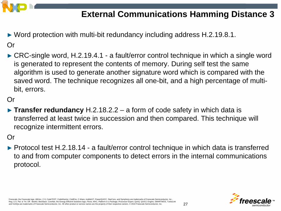
External Communications Hamming Distance 3
► Word protection with multi-bit redundancy including address H.2.19.8.1.Or► CRC-single word, H.2.19.4.1 - a fault/error control technique in which a single word
is generated to represent the contents of memory. During self test the same algorithm is used to generate another signature word which is compared with the saved word. The technique recognizes all one-bit, and a high percentage of multi-bit, errors.
Or► Transfer redundancy H.2.18.2.2 – a form of code safety in which data is
transferred at least twice in succession and then compared. This technique will recognize intermittent errors.
Or► Protocol test H.2.18.14 - a fault/error control technique in which data is transferred
to and from computer components to detect errors in the internal communications protocol.
Presenter
Presentation Notes
This component is intended to check the reliability of the communications to other external modules for example external sensors and actuators that are not placed on the electronic control PCB. Four possible measures are given to test this component Transfer Redundancy is probably the most cost efficient and easiest measure to deploy for ensuring reliable and safe external communications. This measure can be easily implemented in the software that is used in the communications protocol to send and receive data twice before executing on commands or results received. CRC single word check can also be easily utilised, by appending a 16bit signature of the data in with the message being communicated. For communication protocols that exchange small data/message packets and have no time-constraints then it is possible to use a software CRC engine, but if there is some high speed requirements then a hardware CRC engine is preferred.
TMFreescale, the Freescale logo, AltiVec, C-5, CodeTEST, CodeWarrior, ColdFire, C-Ware, mobileGT, PowerQUICC, StarCore, and Symphony are trademarks of Freescale Semiconductor, Inc., Reg. U.S. Pat. & Tm. Off. BeeKit, BeeStack, CoreNet, the Energy Efficient Solutions logo, Flexis, MXC, Platform in a Package, Processor Expert, QorIQ, QUICC Engine, SMARTMOS, TurboLink and VortiQa are trademarks of Freescale Semiconductor, Inc. All other product or service names are the property of their respective owners. © 2010 Freescale Semiconductor, Inc. 28
Plausibility Check
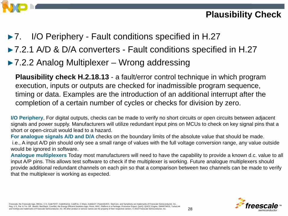
►7. I/O Periphery - Fault conditions specified in H.27►7.2.1 A/D & D/A converters - Fault conditions specified in H.27►7.2.2 Analog Multiplexer – Wrong addressing
Plausibility check H.2.18.13 - a fault/error control technique in which program execution, inputs or outputs are checked for inadmissible program sequence, timing or data. Examples are the introduction of an additional interrupt after the completion of a certain number of cycles or checks for division by zero.
I/O Periphery, For digital outputs, checks can be made to verify no short circuits or open circuits between adjacent signals and power supply. Manufacturers will utilize redundant input pins on MCUs to check on key signal pins that a short or open-circuit would lead to a hazard.For analogue signals A/D and D/A checks on the boundary limits of the absolute value that should be made.i.e., A input A/D pin should only see a small range of values with the full voltage conversion range, any value outside would be ignored in software.Analogue multiplexers Today most manufacturers will need to have the capability to provide a known d.c. value to all input A/P pins. This allows test software to check if the multiplexer is working. Future analogue multiplexers should provide additional redundant channels on each pin so that a comparison between two channels can be made to verify that the multiplexer is working as expected.
Presenter
Presentation Notes
For class B controls a plausibility check is the only measure required for testing the following components. 7. I/O Periphery - Fault conditions specified in H.27 7.2.1 A/D & D/A converters - Fault conditions specified in H.27 7.2.2 Analog Multiplexer – Wrong addressing Plausibility checks tests that are carried out to stress the appliance product prior to running the application code, by introducing short circuits, open circuits and/or placing out of operation conditions on individual components, or placing boundary conditions around features while running the application. I/O Periphery, For digital outputs checks can be made to verify no short circuits or open circuits between adjacent signals and power supply .Manufacturers will utilize redundant input pins on MCU’s to check on key signal pins that a short or open-circuit would lead to a hazard. For analogue signals A/D and D/A checks on the boundary limits of the absolute value should be made. I.e. A input A/D pin should only see a small range of values with the full voltage conversion range, any value outside would be ignored in software. Analogue multiplexers Today most manufacturers will need to have the capability to provide a known d.c. value to all input A/P pins. This allows test software to check the multiplexer is working. Future analogue multiplexers should provide additional redundant channels on each pin so that a comparison between two channels can be made to verify that the multiplexer is working as expected.

TMFreescale, the Freescale logo, AltiVec, C-5, CodeTEST, CodeWarrior, ColdFire, C-Ware, mobileGT, PowerQUICC, StarCore, and Symphony are trademarks of Freescale Semiconductor, Inc., Reg. U.S. Pat. & Tm. Off. BeeKit, BeeStack, CoreNet, the Energy Efficient Solutions logo, Flexis, MXC, Platform in a Package, Processor Expert, QorIQ, QUICC Engine, SMARTMOS, TurboLink and VortiQa are trademarks of Freescale Semiconductor, Inc. All other product or service names are the property of their respective owners. © 2010 Freescale Semiconductor, Inc. 29
Class B Generic MCU Requirements Summary
Hardware► Independent clocked WDOG ► Independent Real Time interruptNice to have:► CRC Engine for 64K+ memory devices► Loss of Clock/Lock Reset
Software► CPU Register “SA faults” Test► March C and MARCH X (transparent) RAM Test► Modified Checksum or CRC Flash Test► Independent WDOG Test► Plausibility Tests for key digital and analog I/O signals
► Time Slot monitoring of program flow ► and interrupt behavior
• Token passing• Independent RTI
ind clk WDOG
CPU
RAM
Flash
MCU
ind clk RTI
CRC
Presenter
Presentation Notes
So for generic class B systems an embedded MCU system should have the following software and hardware features. Software CPU Register “SA faults” Test March C and MARCH X (transparent) RAM Test Modified Checksum or CRC Flash Test. Independent WDOG Test Plausibility Tests for key digital and analogue I/O signals Time Slot monitoring of program flow and interrupt behavior. token passing independent RTI Hardware Independent clocked WDOG Independent Real Time interrupt Nice to have CRC Engine for 64K+ memory devices Loss of Clock/Lock Reset

TMFreescale, the Freescale logo, AltiVec, C-5, CodeTEST, CodeWarrior, ColdFire, C-Ware, mobileGT, PowerQUICC, StarCore, and Symphony are trademarks of Freescale Semiconductor, Inc., Reg. U.S. Pat. & Tm. Off. BeeKit, BeeStack, CoreNet, the Energy Efficient Solutions logo, Flexis, MXC, Platform in a Package, Processor Expert, QorIQ, QUICC Engine, SMARTMOS, TurboLink and VortiQa are trademarks of Freescale Semiconductor, Inc. All other product or service names are the property of their respective owners. © 2010 Freescale Semiconductor, Inc.
Class C
TMFreescale, the Freescale logo, AltiVec, C-5, CodeTEST, CodeWarrior, ColdFire, C-Ware, mobileGT, PowerQUICC, StarCore, and Symphony are trademarks of Freescale Semiconductor, Inc., Reg. U.S. Pat. & Tm. Off. BeeKit, BeeStack, CoreNet, the Energy Efficient Solutions logo, Flexis, MXC, Platform in a Package, Processor Expert, QorIQ, QUICC Engine, SMARTMOS, TurboLink and VortiQa are trademarks of Freescale Semiconductor, Inc. All other product or service names are the property of their respective owners. © 2010 Freescale Semiconductor, Inc. 31
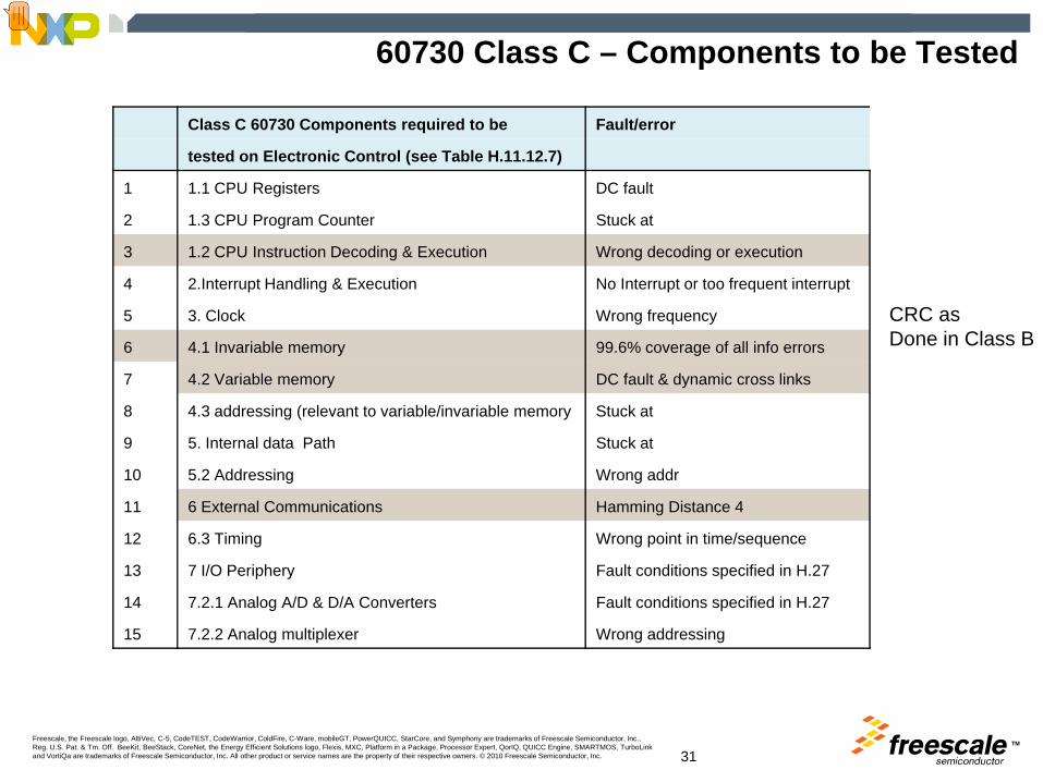
60730 Class C – Components to be Tested
Class C 60730 Components required to be Fault/error
tested on Electronic Control (see Table H.11.12.7)
1 1.1 CPU Registers DC fault
2 1.3 CPU Program Counter Stuck at
3 1.2 CPU Instruction Decoding & Execution Wrong decoding or execution
4 2.Interrupt Handling & Execution No Interrupt or too frequent interrupt
5 3. Clock Wrong frequency
6 4.1 Invariable memory 99.6% coverage of all info errors
7 4.2 Variable memory DC fault & dynamic cross links
8 4.3 addressing (relevant to variable/invariable memory Stuck at
9 5. Internal data Path Stuck at
10 5.2 Addressing Wrong addr
11 6 External Communications Hamming Distance 4
12 6.3 Timing Wrong point in time/sequence
13 7 I/O Periphery Fault conditions specified in H.27
14 7.2.1 Analog A/D & D/A Converters Fault conditions specified in H.27
15 7.2.2 Analog multiplexer Wrong addressing
CRC asDone in Class B
Presenter
Presentation Notes
For Class C systems on extra component to be tested is the CPU Instruction Decoding & Exceution. Additionally 3 other components require further more stringent testing. Invariable memory Variable Memory And External Communications.

TMFreescale, the Freescale logo, AltiVec, C-5, CodeTEST, CodeWarrior, ColdFire, C-Ware, mobileGT, PowerQUICC, StarCore, and Symphony are trademarks of Freescale Semiconductor, Inc., Reg. U.S. Pat. & Tm. Off. BeeKit, BeeStack, CoreNet, the Energy Efficient Solutions logo, Flexis, MXC, Platform in a Package, Processor Expert, QorIQ, QUICC Engine, SMARTMOS, TurboLink and VortiQa are trademarks of Freescale Semiconductor, Inc. All other product or service names are the property of their respective owners. © 2010 Freescale Semiconductor, Inc. 32
Class C Test Matrix
PeriodicSelf checks
Indep. WDOG
S/W Design
ECC type
Dual MCU/CPU/channel
S/W Design
Components
Optional Measures
1.1
Reg
iste
rs:D
C fa
ult
1.2W
rong
dec
odin
g &
exec
utio
n
1.3
Prog
ram
Cou
nter
Stu
ck a
t
1.4
Addr
essi
ng: D
C F
ault
1.5
Dat
a pa
ths
inst
r. D
ecod
eing
: DC
faul
t & e
xecu
tion
2. In
terr
upt h
andl
ing
&exe
cutio
n
3.C
lock
4.1
Inva
riabl
e m
emor
y:99
.6%
of a
ll in
for e
rror
s
Varia
ble
mem
ory:
DC
faul
t dyn
amic
cro
ss li
nks
4.3
addr
essi
ng o
both
var
iabl
e &
inva
riabl
:dc
faul
t
5.In
tern
al D
ata
path
: DC
faul
t
5.2
Wro
ng a
ddre
ss
6. E
xter
nal C
omm
s: h
amm
ing
dist
4
6.2
Addr
essi
ng
6.4
Tim
ing
7.I/O
Per
iphe
ry
7.2
Anal
og
Acceptable measures DefininitionsComparison of redundant CPUs by either 1 1 -reciprocal comparison H.2.18.15 X X X X X X X X X X X X X X X X X -independent hardware comparator, H.2.18.3 X X X X X X X X X X X X X X X X Xinput comparison H.2.18.8 X Xmultiple parallel outputs H.2.18.11 X Xoutput verification H.2.18.12 X Xtesting pattern H.2.18.22 X Xcode safety H.2.18.2 X
Internal error detection, H.2.18.9 X X Xredundant memory with comparison, H.2.19.5 X X X
Periodic self-test using either - walkpat memory test H.2.19.7 X X - Abraham test H.2.19.1 X X - transparent GALPAT test H.2.19.2.1 X X
word protection with multi-bit redundancy H.2.19.8.1 X X X X X X Xincluding the address, or data redundancy, H.2.18.2.1 X X Xstatic memory test and word protection H.2.19.6 X with single bit redundancy H.2.20.8.2 XPeriodic self-test using equivelance class test H.2.18.5 XPeriodic self-test and monitoring using either H.2.16.7 X X X -independent time-slot and logical monitoring H.2.18.10.3 X X X - internal error detection H.2.18.9 Xthe address lines H.2.18.22 X X X X Xfull bit bus parity including the address H.2.18.1.1 X X XPeriodic self-test using a testing pattern of:multibit parity H.2.18.1.2 XFrequency monitoring H.2.18.10.1 Xtime-slot monitoring H.2.18.10.4 X Xcrc -single word H.2.19.4.1 X X Xcrc -double word H.2.19.4.2 X X X Xprotocol test H.2.18.14 X Xtransfer redundancy H.2.18.2.2 Xscheduled transmission H.2.18.18 XLogical monitoring H.2.18.10.2 X
Presenter
Presentation Notes
Optional Measures for testing the required components for class C. Note: again many ways to conform to class C Red line : if you have 2 MCUs or 2 CPUs (and their software design enforces comparisons of data prior to making actions on safety critical routines) then this design will fulfil class C, without the other needs of CRC, CPU instruction tests. But a independent watchdog would still be required to protect against a faulty CPU clock. Blue line. fulfulling class C with no ECC or Dual CPU system can be achieved by periodic tests (CRC, RAM tests, CPU instruction tests) and careful software flow design. Taking the RED line approach will require synchronising the two MCU/CPUs periodically and at critical decision times before making an action, compared to the BLUE line approach where extensive periodic testing would need to be developed in the system interrupting the application code regularly. Blue line is seen as more time required in development but overall lower cost in long term as no need for dual MCU/CPU.
TMFreescale, the Freescale logo, AltiVec, C-5, CodeTEST, CodeWarrior, ColdFire, C-Ware, mobileGT, PowerQUICC, StarCore, and Symphony are trademarks of Freescale Semiconductor, Inc., Reg. U.S. Pat. & Tm. Off. BeeKit, BeeStack, CoreNet, the Energy Efficient Solutions logo, Flexis, MXC, Platform in a Package, Processor Expert, QorIQ, QUICC Engine, SMARTMOS, TurboLink and VortiQa are trademarks of Freescale Semiconductor, Inc. All other product or service names are the property of their respective owners. © 2010 Freescale Semiconductor, Inc. 33
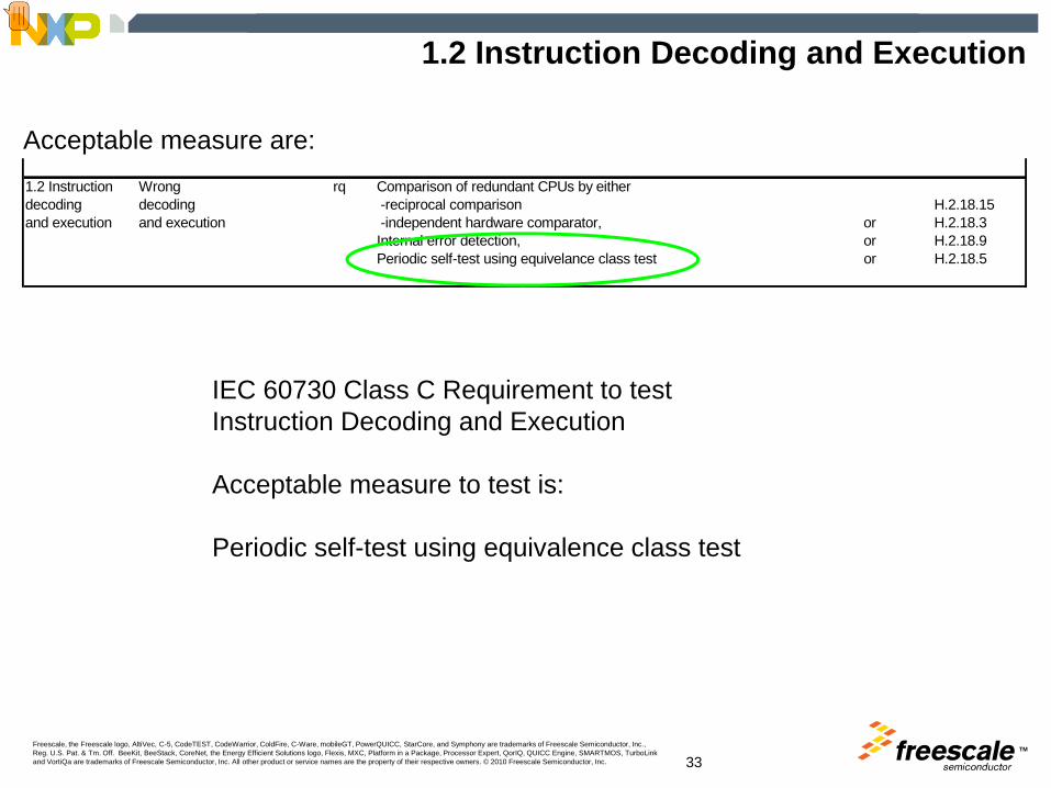
1.2 Instruction Decoding and Execution
1.2 Instruction Wrong rq Comparison of redundant CPUs by eitherdecoding decoding -reciprocal comparison H.2.18.15and execution and execution -independent hardware comparator, or H.2.18.3
Internal error detection, or H.2.18.9Periodic self-test using equivelance class test or H.2.18.5
Acceptable measure are:
IEC 60730 Class C Requirement to testInstruction Decoding and Execution
Acceptable measure to test is:
Periodic self-test using equivalence class test
Presenter
Presentation Notes
For single channel Class C systems the CPU Instruction Decoding & Execution component details that a periodic self test equivelance class test should be carried out.

TMFreescale, the Freescale logo, AltiVec, C-5, CodeTEST, CodeWarrior, ColdFire, C-Ware, mobileGT, PowerQUICC, StarCore, and Symphony are trademarks of Freescale Semiconductor, Inc., Reg. U.S. Pat. & Tm. Off. BeeKit, BeeStack, CoreNet, the Energy Efficient Solutions logo, Flexis, MXC, Platform in a Package, Processor Expert, QorIQ, QUICC Engine, SMARTMOS, TurboLink and VortiQa are trademarks of Freescale Semiconductor, Inc. All other product or service names are the property of their respective owners. © 2010 Freescale Semiconductor, Inc. 34
H.2.18.5 Equivalence Class Test
► H.2.18.5 equivalence class test
► A systematic test intended to determine whether the instruction decoding and execution are performed correctly. The test data is derived from the CPU instruction specification.
► Similar instructions are grouped and the input data set is subdivided into specific data intervals (equivalence classes). Each instruction within a group processes at least one set of test data, so that the entire group processes the entire test data set. The test can be formed from the following:
• Data from a valid range• Data from invalid range• Data from the bounds• Extreme values and their combinations
► The tests within a group are run with different addressing modes, so that the entire group executes all addressing modes
Presenter
Presentation Notes
H.2.18.5 equivalence class test A systematic test intended to determine whether the instruction decoding and execution are performed correctly. The test data is derived from the CPU instruction specification. Similar instructions are grouped and the input data set is subdivided into specific data intervals (equivalence classes) Each instruction within a group processes at least one set of test data, so that the entire group processes the entire test data set. The test can be formed from the following: - data from a valid range - data from invalid range - data from the bounds - extreme values and their combinations The tests within a group are run with different addressing modes, so that the entire group executes all addressing modes.
TMFreescale, the Freescale logo, AltiVec, C-5, CodeTEST, CodeWarrior, ColdFire, C-Ware, mobileGT, PowerQUICC, StarCore, and Symphony are trademarks of Freescale Semiconductor, Inc., Reg. U.S. Pat. & Tm. Off. BeeKit, BeeStack, CoreNet, the Energy Efficient Solutions logo, Flexis, MXC, Platform in a Package, Processor Expert, QorIQ, QUICC Engine, SMARTMOS, TurboLink and VortiQa are trademarks of Freescale Semiconductor, Inc. All other product or service names are the property of their respective owners. © 2010 Freescale Semiconductor, Inc. 35
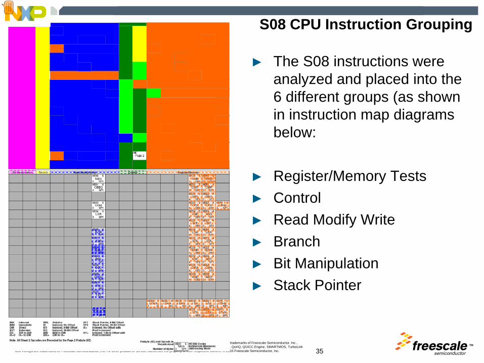
S08 CPU Instruction Grouping
► The S08 instructions were analyzed and placed into the 6 different groups (as shown in instruction map diagrams below:
► Register/Memory Tests► Control► Read Modify Write► Branch► Bit Manipulation► Stack Pointer
Presenter
Presentation Notes
For example for the S08 CPU, Freescale has developed a CPU Instruction Test. The 300 instructions were analysed and split into 6 groups. Register/Memory Tests Control Read Modify Write Branch Bit Manipulation Stack Pointer Tests were developed for each group. The various addressing modes that are included in all the Register/Memory instructions, were tested only on a few of the instructions rather than testing every addressing mode on every instruction.
TMFreescale, the Freescale logo, AltiVec, C-5, CodeTEST, CodeWarrior, ColdFire, C-Ware, mobileGT, PowerQUICC, StarCore, and Symphony are trademarks of Freescale Semiconductor, Inc., Reg. U.S. Pat. & Tm. Off. BeeKit, BeeStack, CoreNet, the Energy Efficient Solutions logo, Flexis, MXC, Platform in a Package, Processor Expert, QorIQ, QUICC Engine, SMARTMOS, TurboLink and VortiQa are trademarks of Freescale Semiconductor, Inc. All other product or service names are the property of their respective owners. © 2010 Freescale Semiconductor, Inc. 36
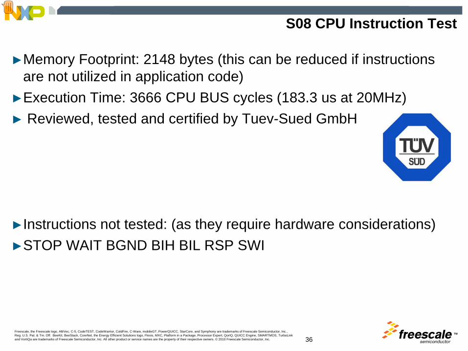
S08 CPU Instruction Test
►Memory Footprint: 2148 bytes (this can be reduced if instructions are not utilized in application code)
►Execution Time: 3666 CPU BUS cycles (183.3 us at 20MHz)► Reviewed, tested and certified by Tuev-Sued GmbH
►Instructions not tested: (as they require hardware considerations)►STOP WAIT BGND BIH BIL RSP SWI
Presenter
Presentation Notes
Memory Footprint: 2148 bytes (this can be reduced if instructions are not utilised in application code) Execution Time: 3666 CPU BUS cycles (183.3 us at 20MHz) Reviewed, tested and certified by Tuev-Sued GmbH. Instructions not tested: (as they require hardware considerations) STOP WAIT BGND BIH BIL RSP SWI This Test has been certified by Tuev-Sud Gmbh to be compliance to class C 60730.
TMFreescale, the Freescale logo, AltiVec, C-5, CodeTEST, CodeWarrior, ColdFire, C-Ware, mobileGT, PowerQUICC, StarCore, and Symphony are trademarks of Freescale Semiconductor, Inc., Reg. U.S. Pat. & Tm. Off. BeeKit, BeeStack, CoreNet, the Energy Efficient Solutions logo, Flexis, MXC, Platform in a Package, Processor Expert, QorIQ, QUICC Engine, SMARTMOS, TurboLink and VortiQa are trademarks of Freescale Semiconductor, Inc. All other product or service names are the property of their respective owners. © 2010 Freescale Semiconductor, Inc. 37
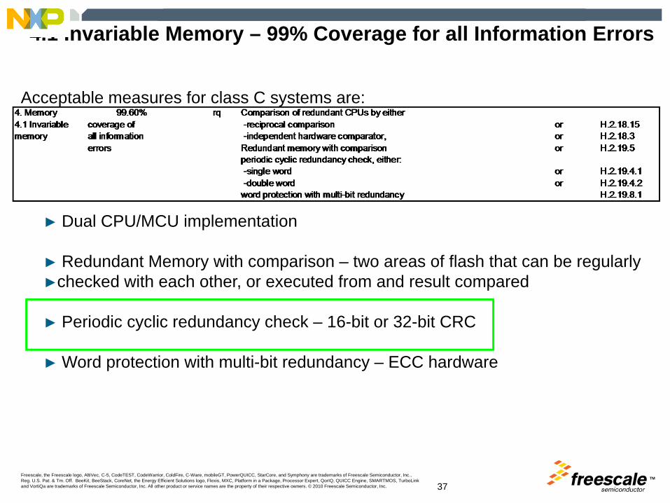
4.1 Invariable Memory – 99% Coverage for all Information Errors
► Dual CPU/MCU implementation
► Redundant Memory with comparison – two areas of flash that can be regularly►checked with each other, or executed from and result compared
► Periodic cyclic redundancy check – 16-bit or 32-bit CRC
► Word protection with multi-bit redundancy – ECC hardware
Acceptable measures for class C systems are:

TMFreescale, the Freescale logo, AltiVec, C-5, CodeTEST, CodeWarrior, ColdFire, C-Ware, mobileGT, PowerQUICC, StarCore, and Symphony are trademarks of Freescale Semiconductor, Inc., Reg. U.S. Pat. & Tm. Off. BeeKit, BeeStack, CoreNet, the Energy Efficient Solutions logo, Flexis, MXC, Platform in a Package, Processor Expert, QorIQ, QUICC Engine, SMARTMOS, TurboLink and VortiQa are trademarks of Freescale Semiconductor, Inc. All other product or service names are the property of their respective owners. © 2010 Freescale Semiconductor, Inc. 38
4.2 Variable Memory
Acceptable measures for class C systems are:
►IEC 60730 Class C Requirement to test►Variable memory (RAM) for DC faults
►Acceptable measure to test is:
►Periodic self-test using “walkpat memory test”
Presenter
Presentation Notes
For variable memeory RAM, for class C a more stringent test described is the walkpat memory test.

TMFreescale, the Freescale logo, AltiVec, C-5, CodeTEST, CodeWarrior, ColdFire, C-Ware, mobileGT, PowerQUICC, StarCore, and Symphony are trademarks of Freescale Semiconductor, Inc., Reg. U.S. Pat. & Tm. Off. BeeKit, BeeStack, CoreNet, the Energy Efficient Solutions logo, Flexis, MXC, Platform in a Package, Processor Expert, QorIQ, QUICC Engine, SMARTMOS, TurboLink and VortiQa are trademarks of Freescale Semiconductor, Inc. All other product or service names are the property of their respective owners. © 2010 Freescale Semiconductor, Inc. 39
H.2.19.7 Equivalence Class Test
►H.2.19.7 walkpat memory test►A fault/error control technique in which a standard data pattern is
written to the memory area under test as in normal operation. A bit inversion is performed on the first cell and the remaining memory areas is inspected. Then the first cell is again inverted and the memory inspected. This process is repeated for all memory cells under test. A second test is conducted by performing a bit inversion of all cells in memory under test and preceding as above.
►This technique recognizes all static bit errors as well as errors in interfaces between memory cells
A walking 1s pattern followed by a walking 0s pattern
TMFreescale, the Freescale logo, AltiVec, C-5, CodeTEST, CodeWarrior, ColdFire, C-Ware, mobileGT, PowerQUICC, StarCore, and Symphony are trademarks of Freescale Semiconductor, Inc., Reg. U.S. Pat. & Tm. Off. BeeKit, BeeStack, CoreNet, the Energy Efficient Solutions logo, Flexis, MXC, Platform in a Package, Processor Expert, QorIQ, QUICC Engine, SMARTMOS, TurboLink and VortiQa are trademarks of Freescale Semiconductor, Inc. All other product or service names are the property of their respective owners. © 2010 Freescale Semiconductor, Inc. 40
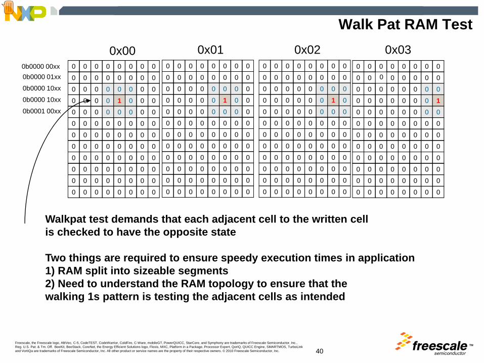
Walk Pat RAM Test
0 0 0 0 0 0 0 0
0 0 0 0 0 0 0 0
0 0 0 0 0 0 0 0
0 0 0 0 0 0 0 10 0 0 0 0 0 0 0
0 0 0 0 0 0 0 0
0 0 0 0 0 0 0 0
0 0 0 0 0 0 0 0
0 0 0 0 0 0 0 0
0 0 0 0 0 0 0 0
0 0 0 0 0 0 0 0
0 0 0 0 0 0 0 0
0 0 0 0 0 0 0 0
0 0 0 0 0 0 0 0
0 0 0 0 0 0 0 0
0 0 0 0 0 0 1 0
0 0 0 0 0 0 0 0
0 0 0 0 0 0 0 0
0 0 0 0 0 0 0 0
0 0 0 0 0 0 0 0
0 0 0 0 0 0 0 0
0 0 0 0 0 0 0 0
0 0 0 0 0 0 0 0
0 0 0 0 0 0 0 0
0 0 0 0 0 0 0 0
0 0 0 0 0 0 0 0
0 0 0 0 0 0 0 0
0 0 0 0 0 1 0 0
0 0 0 0 0 0 0 0
0 0 0 0 0 0 0 0
0 0 0 0 0 0 0 0
0 0 0 0 0 0 0 0
0 0 0 0 0 0 0 0
0 0 0 0 0 0 0 0
0 0 0 0 0 0 0 0
0 0 0 0 0 0 0 0
0 0 0 0 0 0 0 0
0 0 0 0 0 0 0 0
0 0 0 0 0 0 0 0
0 0 0 0 01 0 0
0 0 0 0 0 0 0 0
0 0 0 0 0 0 0 0
0 0 0 0 0 0 0 0
0 0 0 0 0 0 0 0
0 0 0 0 0 0 0 0
0 0 0 0 0 0 0 0
0 0 0 0 0 0 0 0
0 0 0 0 0 0 0 0
0x00 0x020x01 0x030b0000 00xx0b0000 01xx
0b0000 10xx
0b0000 10xx
0b0001 00xx
Walkpat test demands that each adjacent cell to the written cellis checked to have the opposite state
Two things are required to ensure speedy execution times in application1) RAM split into sizeable segments2) Need to understand the RAM topology to ensure that thewalking 1s pattern is testing the adjacent cells as intended
Presenter
Presentation Notes
The walkpat test consists of setting array to a fixed logic value all 0s then writing a 1 to a bit location and verifying surrounding bits are not affected by the write. The 1 is walked through the array. It is required to test the RAM with walking 1s and walking 0s. This as can be seen a very intensive test and takes considerable execution time to complete, and always destruictive in nature. To speed up executions times and make this a transparent test then the RAM should split into segements as small as possible and tested in a round robin fashion. Additionaly the RAM topology needs to examined as in a lot of case the logical address(from how the CPU accesses the RAM) and the actual physical layout of the bits may differ and this needs to examined to ensure the test code examines the true adjacent bits. The MCU manufacturer should be able to supply this data on request.
TMFreescale, the Freescale logo, AltiVec, C-5, CodeTEST, CodeWarrior, ColdFire, C-Ware, mobileGT, PowerQUICC, StarCore, and Symphony are trademarks of Freescale Semiconductor, Inc., Reg. U.S. Pat. & Tm. Off. BeeKit, BeeStack, CoreNet, the Energy Efficient Solutions logo, Flexis, MXC, Platform in a Package, Processor Expert, QorIQ, QUICC Engine, SMARTMOS, TurboLink and VortiQa are trademarks of Freescale Semiconductor, Inc. All other product or service names are the property of their respective owners. © 2010 Freescale Semiconductor, Inc. 41
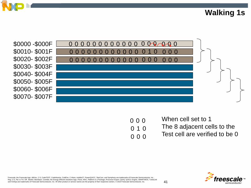
Walking 1s
$0000 -$000F$0010- $001F$0020- $002F$0030- $003F$0040- $004F$0050- $005F$0060- $006F$0070- $007F
1000
000000
0000
00000
0000
00000
0000
00000
0000
0000 0
0000
0000
1000
00000
When cell set to 1The 8 adjacent cells to theTest cell are verified to be 0
Presenter
Presentation Notes
For the S08AC60 a Walkpat test was developed by Freescale. The RAM was segmented into 16byte segments to be tested. Each 16byte segment requires you to test the previous and next 16byte locations thus the test needs to access 48bytes at any time. Thus a 48byte redundant segment was used to store the temporary application data while the WALKPAT test was executed on the 16bytes. In a round robin fashion the each of the 16bytes was tested.
TMFreescale, the Freescale logo, AltiVec, C-5, CodeTEST, CodeWarrior, ColdFire, C-Ware, mobileGT, PowerQUICC, StarCore, and Symphony are trademarks of Freescale Semiconductor, Inc., Reg. U.S. Pat. & Tm. Off. BeeKit, BeeStack, CoreNet, the Energy Efficient Solutions logo, Flexis, MXC, Platform in a Package, Processor Expert, QorIQ, QUICC Engine, SMARTMOS, TurboLink and VortiQa are trademarks of Freescale Semiconductor, Inc. All other product or service names are the property of their respective owners. © 2010 Freescale Semiconductor, Inc. 42
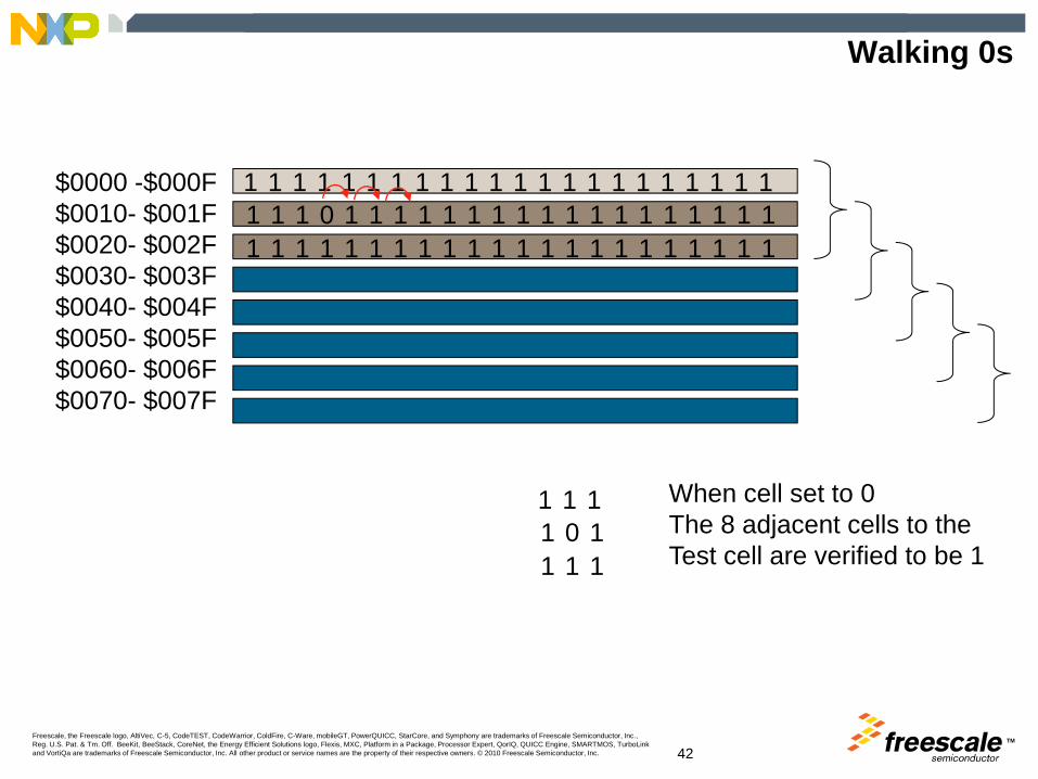
Walking 0s
$0000 -$000F$0010- $001F$0020- $002F$0030- $003F$0040- $004F$0050- $005F$0060- $006F$0070- $007F
111
0111
11111
When cell set to 0The 8 adjacent cells to theTest cell are verified to be 1
111
111
101
111
111
111
111
111
111
111
111
111
111
111
111
111
111
111
111
111
111
TMFreescale, the Freescale logo, AltiVec, C-5, CodeTEST, CodeWarrior, ColdFire, C-Ware, mobileGT, PowerQUICC, StarCore, and Symphony are trademarks of Freescale Semiconductor, Inc., Reg. U.S. Pat. & Tm. Off. BeeKit, BeeStack, CoreNet, the Energy Efficient Solutions logo, Flexis, MXC, Platform in a Package, Processor Expert, QorIQ, QUICC Engine, SMARTMOS, TurboLink and VortiQa are trademarks of Freescale Semiconductor, Inc. All other product or service names are the property of their respective owners. © 2010 Freescale Semiconductor, Inc. 43
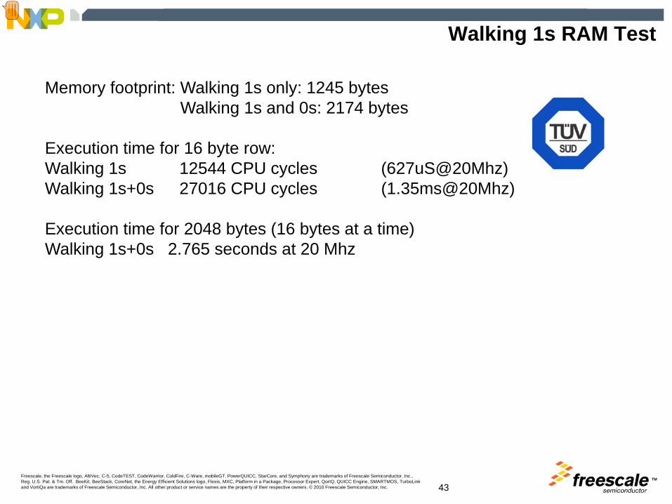
Walking 1s RAM Test
Memory footprint: Walking 1s only: 1245 bytesWalking 1s and 0s: 2174 bytes
Execution time for 16 byte row: Walking 1s 12544 CPU cycles (627uS@20Mhz)Walking 1s+0s 27016 CPU cycles (1.35ms@20Mhz)
Execution time for 2048 bytes (16 bytes at a time)Walking 1s+0s 2.765 seconds at 20 Mhz
Presenter
Presentation Notes
On completion Freescale has designed the S08 RAM test (2kBytes) Memory footprint: Walking 1s only: 1245 bytes Walking1s and 0s: 2174 bytes Execution time for 16 byte row: Walking1s 12544 CPU cycles (627uS@20Mhz) Walking1s+0s 27016 CPU cycles (1.35ms@20Mhz) Execution time for 2048bytes (16bytes at a time) Walking 1s+0s 2.765 seconds @20Mhz Again this test suite has been certified by Tuev Sued as Class C 607390 compliant

TMFreescale, the Freescale logo, AltiVec, C-5, CodeTEST, CodeWarrior, ColdFire, C-Ware, mobileGT, PowerQUICC, StarCore, and Symphony are trademarks of Freescale Semiconductor, Inc., Reg. U.S. Pat. & Tm. Off. BeeKit, BeeStack, CoreNet, the Energy Efficient Solutions logo, Flexis, MXC, Platform in a Package, Processor Expert, QorIQ, QUICC Engine, SMARTMOS, TurboLink and VortiQa are trademarks of Freescale Semiconductor, Inc. All other product or service names are the property of their respective owners. © 2010 Freescale Semiconductor, Inc. 44
6.1 External Communication Data – Hamming Distance 4
► CRC double word – 32-bit CRC of data transmitted/received
► Data redundancy with comparison – send data twice and comparison
► Comparison of redundant function channels – use two interface mediums and compare receptions with each other

TMFreescale, the Freescale logo, AltiVec, C-5, CodeTEST, CodeWarrior, ColdFire, C-Ware, mobileGT, PowerQUICC, StarCore, and Symphony are trademarks of Freescale Semiconductor, Inc., Reg. U.S. Pat. & Tm. Off. BeeKit, BeeStack, CoreNet, the Energy Efficient Solutions logo, Flexis, MXC, Platform in a Package, Processor Expert, QorIQ, QUICC Engine, SMARTMOS, TurboLink and VortiQa are trademarks of Freescale Semiconductor, Inc. All other product or service names are the property of their respective owners. © 2010 Freescale Semiconductor, Inc.
Freescale Offerings
TMFreescale, the Freescale logo, AltiVec, C-5, CodeTEST, CodeWarrior, ColdFire, C-Ware, mobileGT, PowerQUICC, StarCore, and Symphony are trademarks of Freescale Semiconductor, Inc., Reg. U.S. Pat. & Tm. Off. BeeKit, BeeStack, CoreNet, the Energy Efficient Solutions logo, Flexis, MXC, Platform in a Package, Processor Expert, QorIQ, QUICC Engine, SMARTMOS, TurboLink and VortiQa are trademarks of Freescale Semiconductor, Inc. All other product or service names are the property of their respective owners. © 2010 Freescale Semiconductor, Inc. 46
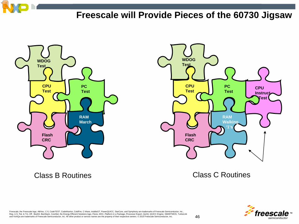
Freescale will Provide Pieces of the 60730 Jigsaw
FlashCRC
WDOGTest
CPUTest
PCTest
RAMMarch
FlashCRC
WDOGTest
CPUTest
PCTest
RAMWalking
‘1’s
CPUInstruct.
Test
Class B Routines Class C Routines
Presenter
Presentation Notes
In addition to the two class C routine developed for S08ACxx devices, Freescale has also developed other tests for other platforms. These tests are available to customers free of charge from freescale. Note these periodic test routines will aid manufacturers in their development cycle, but on their own they do not make a system 60730 compliant and thus are pieces of the comepleting the 60730 jigsaw. Manufacturers still have to develop their own time-slot monitoring routines, plausibility tests, and communication software. With these and what Freescale provide the manufacturer will be very close to meeting 60730 certification.

TMFreescale, the Freescale logo, AltiVec, C-5, CodeTEST, CodeWarrior, ColdFire, C-Ware, mobileGT, PowerQUICC, StarCore, and Symphony are trademarks of Freescale Semiconductor, Inc., Reg. U.S. Pat. & Tm. Off. BeeKit, BeeStack, CoreNet, the Energy Efficient Solutions logo, Flexis, MXC, Platform in a Package, Processor Expert, QorIQ, QUICC Engine, SMARTMOS, TurboLink and VortiQa are trademarks of Freescale Semiconductor, Inc. All other product or service names are the property of their respective owners. © 2010 Freescale Semiconductor, Inc. 47
Available now
S088-bit
DSC16-bit
CFv132-bit
2007 2010
Class C
Class C
Class C
Freescale 60730 Software Roadmap
Presenter
Presentation Notes
Currently For Class B systems Freescale has developed routines for S08 8bit platform, and the DSC56F80xx platform of MCUs. For Class C systems Freescale has completed S08 additional tests being the CPU instruction and RAM walking 1.0s test. Planned are tests for Freescale 32bit Coldfire V1 core. And class C for DSC products.
TMFreescale, the Freescale logo, AltiVec, C-5, CodeTEST, CodeWarrior, ColdFire, C-Ware, mobileGT, PowerQUICC, StarCore, and Symphony are trademarks of Freescale Semiconductor, Inc., Reg. U.S. Pat. & Tm. Off. BeeKit, BeeStack, CoreNet, the Energy Efficient Solutions logo, Flexis, MXC, Platform in a Package, Processor Expert, QorIQ, QUICC Engine, SMARTMOS, TurboLink and VortiQa are trademarks of Freescale Semiconductor, Inc. All other product or service names are the property of their respective owners. © 2010 Freescale Semiconductor, Inc. 48
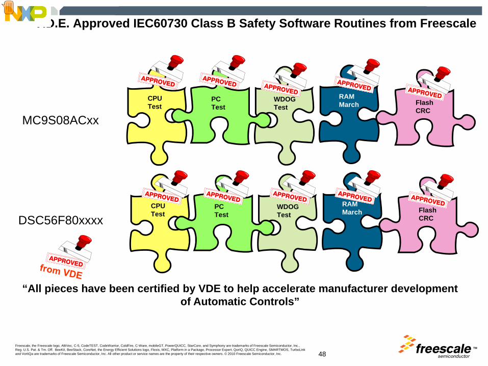
V.D.E. Approved IEC60730 Class B Safety Software Routines from Freescale
FlashCRC
WDOGTest
CPUTest
PCTest
RAMMarch
“All pieces have been certified by VDE to help accelerate manufacturer developmentof Automatic Controls”
FlashCRC
WDOGTest
CPUTest
PCTest
RAMMarch
MC9S08ACxx
DSC56F80xxxx
Presenter
Presentation Notes
Class B the following tests have been completed. For both S08 and DSC56F80xx family. All approved by VDE GmbH
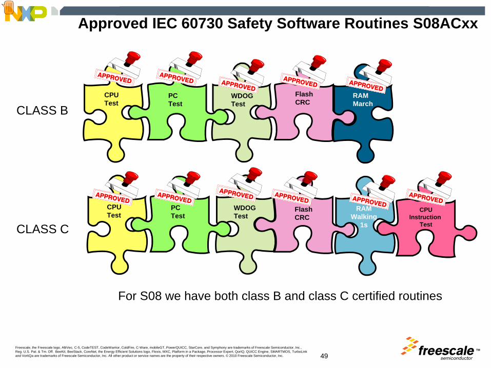
TMFreescale, the Freescale logo, AltiVec, C-5, CodeTEST, CodeWarrior, ColdFire, C-Ware, mobileGT, PowerQUICC, StarCore, and Symphony are trademarks of Freescale Semiconductor, Inc., Reg. U.S. Pat. & Tm. Off. BeeKit, BeeStack, CoreNet, the Energy Efficient Solutions logo, Flexis, MXC, Platform in a Package, Processor Expert, QorIQ, QUICC Engine, SMARTMOS, TurboLink and VortiQa are trademarks of Freescale Semiconductor, Inc. All other product or service names are the property of their respective owners. © 2010 Freescale Semiconductor, Inc. 49
Approved IEC 60730 Safety Software Routines S08ACxx
FlashCRC
WDOGTest
CPUTest
PCTest
RAMMarch
FlashCRC
WDOGTest
CPUTest
PCTest
RAMWalking
1s
CLASS B
CLASS C
CPUInstruction
Test
For S08 we have both class B and class C certified routines
Presenter
Presentation Notes
For S08AC family bot class C and Class B tests have completed and certified by VDE or Tuev Sud GmbH

TMFreescale, the Freescale logo, AltiVec, C-5, CodeTEST, CodeWarrior, ColdFire, C-Ware, mobileGT, PowerQUICC, StarCore, and Symphony are trademarks of Freescale Semiconductor, Inc., Reg. U.S. Pat. & Tm. Off. BeeKit, BeeStack, CoreNet, the Energy Efficient Solutions logo, Flexis, MXC, Platform in a Package, Processor Expert, QorIQ, QUICC Engine, SMARTMOS, TurboLink and VortiQa are trademarks of Freescale Semiconductor, Inc. All other product or service names are the property of their respective owners. © 2010 Freescale Semiconductor, Inc. 50
Generic MCU Requirements for IEC/UL 60730
HardwareIndependent Clocked WDOGIndependent real time interrupt
SoftwareCPU Register “SA faults” TestMarch C and MARCH X (transparent) RAM TestModified Checksum or CRC Flash Test.Independent WDOG TestPlausibility Tests
Time Slot monitoring of program flow and interrupt behavior
HardwareIndependent Clocked WDOGIndependent real time interrupt2nd CPU or CPU Instruction TestCRC engine
SoftwareCPU Register “walkpat” TestCPU Instruction Set TestGALPAT/walking 1’s RAM TestCRC Flash Test.Independent WDOG TestPlausibility Tests
Time Slot monitoring of program flow and interrupt behavior
Class B Class C
Presenter
Presentation Notes
Short: For IEC/UL 60730 a summary of Class B and Class C Requirements are detailed. The main differences are Class C requires additional checks on the CPU instruction and decoding requiring a CPU Instruction Test, and a more stringent RAM test with a Walking 1s pattern.
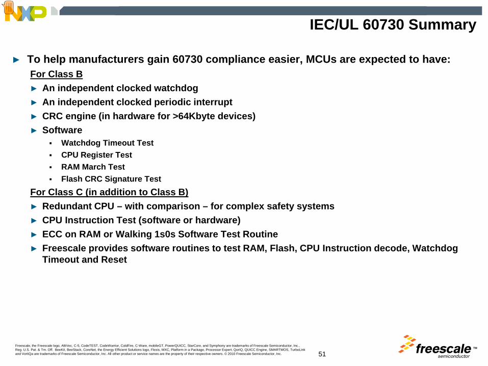
TMFreescale, the Freescale logo, AltiVec, C-5, CodeTEST, CodeWarrior, ColdFire, C-Ware, mobileGT, PowerQUICC, StarCore, and Symphony are trademarks of Freescale Semiconductor, Inc., Reg. U.S. Pat. & Tm. Off. BeeKit, BeeStack, CoreNet, the Energy Efficient Solutions logo, Flexis, MXC, Platform in a Package, Processor Expert, QorIQ, QUICC Engine, SMARTMOS, TurboLink and VortiQa are trademarks of Freescale Semiconductor, Inc. All other product or service names are the property of their respective owners. © 2010 Freescale Semiconductor, Inc. 51
IEC/UL 60730 Summary
► To help manufacturers gain 60730 compliance easier, MCUs are expected to have:For Class B► An independent clocked watchdog► An independent clocked periodic interrupt► CRC engine (in hardware for >64Kbyte devices)► Software
Watchdog Timeout TestCPU Register TestRAM March TestFlash CRC Signature Test
For Class C (in addition to Class B)► Redundant CPU – with comparison – for complex safety systems► CPU Instruction Test (software or hardware)► ECC on RAM or Walking 1s0s Software Test Routine► Freescale provides software routines to test RAM, Flash, CPU Instruction decode, Watchdog
Timeout and Reset
Presenter
Presentation Notes
To help manufacturers gained 60730 compliance easier, MCUs are expected to have: Class B An independent clocked watchdog An independent clocked periodic interrupt CRC engine (in hardware for >64Kbyte devices) Software Watchdog Timeout Test CPU Register Test RAM March Test Flash CRC Signature Test Class C Redundant CPU – with comparison – for complex safety systems CPU Instruction Test (s/w or h/w) ECC on RAM or Walking 1s0s S/W Test Routine Freescale provides software routines to test RAM, Flash, CPU Instruction decode, Watchdog Timeout & Reset.
TM
Related Documents


![IEC 60730-2-9{ed4.1) - Welcome to the IEC Webstoreed4.1}en.pdf · IEC 60730-2-9 edition 4.1 contains the fourth edition (2015-05) [documents 72/990/FDIS and 72/998/RVD] and its amendment](https://static.cupdf.com/doc/110x72/613c5c5e4c23507cb635553c/iec-60730-2-9ed41-welcome-to-the-iec-webstore-ed41enpdf-iec-60730-2-9.jpg)
