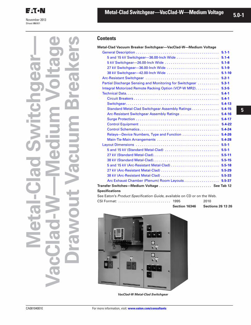
CA08104001E For more information, visit: www.eaton.com/consultants November 2013 Contents Metal-Clad Switchgear—VacClad-W—Medium Voltage 5.0-1 i ii 1 2 3 4 5 6 7 8 9 10 11 12 13 14 15 16 17 18 19 20 21 Sheet 05 001 Metal-Clad Switchgear— VacClad-W—Medium Voltage Drawout Vacuum Breakers Metal-Clad Vacuum Breaker Switchgear—VacClad-W—Medium Voltage General Description . . . . . . . . . . . . . . . . . . . . . . . . . . . . . . . . . . . . . . . . . . . 5.1-1 5 and 15 kV Switchgear—36.00-Inch Wide . . . . . . . . . . . . . . . . . . . . . . 5.1-4 5 kV Switchgear—26.00-Inch Wide . . . . . . . . . . . . . . . . . . . . . . . . . . . . 5.1-8 27 kV Switchgear—36.00-Inch Wide . . . . . . . . . . . . . . . . . . . . . . . . . . . 5.1-9 38 kV Switchgear—42.00-Inch Wide . . . . . . . . . . . . . . . . . . . . . . . . . . . 5.1-10 Arc-Resistant Switchgear . . . . . . . . . . . . . . . . . . . . . . . . . . . . . . . . . . . . . . 5.2-1 Partial Discharge Sensing and Monitoring for Switchgear . . . . . . . . . . . 5.3-1 Integral Motorized Remote Racking Option (VCP-W MR2) . . . . . . . . . . . . 5.3-5 Technical Data. . . . . . . . . . . . . . . . . . . . . . . . . . . . . . . . . . . . . . . . . . . . . . . . 5.4-1 Circuit Breakers . . . . . . . . . . . . . . . . . . . . . . . . . . . . . . . . . . . . . . . . . . . . 5.4-1 Switchgear . . . . . . . . . . . . . . . . . . . . . . . . . . . . . . . . . . . . . . . . . . . . . . . . 5.4-13 Standard Metal-Clad Switchgear Assembly Ratings . . . . . . . . . . . . . . 5.4-15 Arc-Resistant Switchgear Assembly Ratings . . . . . . . . . . . . . . . . . . . . 5.4-16 Surge Protection . . . . . . . . . . . . . . . . . . . . . . . . . . . . . . . . . . . . . . . . . . . 5.4-17 Control Equipment . . . . . . . . . . . . . . . . . . . . . . . . . . . . . . . . . . . . . . . . . 5.4-22 Control Schematics . . . . . . . . . . . . . . . . . . . . . . . . . . . . . . . . . . . . . . . . . 5.4-24 Relays—Device Numbers, Type and Function . . . . . . . . . . . . . . . . . . . 5.4-26 Main-Tie-Main Arrangements . . . . . . . . . . . . . . . . . . . . . . . . . . . . . . . . 5.4-28 Layout Dimensions . . . . . . . . . . . . . . . . . . . . . . . . . . . . . . . . . . . . . . . . . . . 5.5-1 5 and 15 kV (Standard Metal-Clad) . . . . . . . . . . . . . . . . . . . . . . . . . . . . 5.5-1 27 kV (Standard Metal-Clad) . . . . . . . . . . . . . . . . . . . . . . . . . . . . . . . . . . 5.5-11 38 kV (Standard Metal-Clad) . . . . . . . . . . . . . . . . . . . . . . . . . . . . . . . . . . 5.5-15 5 and 15 kV (Arc-Resistant Metal-Clad) . . . . . . . . . . . . . . . . . . . . . . . . . 5.5-18 27 kV (Arc-Resistant Metal-Clad) . . . . . . . . . . . . . . . . . . . . . . . . . . . . . . 5.5-29 38 kV (Arc-Resistant Metal-Clad) . . . . . . . . . . . . . . . . . . . . . . . . . . . . . . 5.5-33 Arc Exhaust Chamber (Plenum) Room Layouts . . . . . . . . . . . . . . . . . . 5.5-37 Transfer Switches—Medium Voltage . . . . . . . . . . . . . . . . . . . . . . . . . . . See Tab 12 Specifications See Eaton’s Product Specification Guide, available on CD or on the Web. CSI Format: . . . . . . . . . . . . . . . . . . . . . . . . . . . 1995 2010 Section 16346 Sections 26 13 26 VacClad-W Metal-Clad Switchgear

Tb 02201001 e
Dec 15, 2015
kgtyfvyjbyjubfgtydebrefyhgthgdrhebtfyh
Welcome message from author
This document is posted to help you gain knowledge. Please leave a comment to let me know what you think about it! Share it to your friends and learn new things together.
Transcript
CA08104001E For more information, visit:
www.eaton.com/consultants
November 2013
Contents
Metal-Clad Switchgear—VacClad-W—Medium Voltage
5.0-1
i
ii
1
2
3
4
5
6
7
8
9
10
11
12
13
14
15
16
17
18
19
20
21
Sheet
05
001
Meta
l-C
lad
Sw
itch
gear—
VacC
lad
-W—
Med
ium
Vo
ltag
eD
raw
ou
t V
acu
um
Bre
akers
Metal-Clad Vacuum Breaker Switchgear—VacClad-W—Medium Voltage
General Description . . . . . . . . . . . . . . . . . . . . . . . . . . . . . . . . . . . . . . . . . . .
5.1-1
5 and 15 kV Switchgear—36.00-Inch Wide . . . . . . . . . . . . . . . . . . . . . .
5.1-4
5 kV Switchgear—26.00-Inch Wide . . . . . . . . . . . . . . . . . . . . . . . . . . . .
5.1-8
27 kV Switchgear—36.00-Inch Wide . . . . . . . . . . . . . . . . . . . . . . . . . . .
5.1-9
38 kV Switchgear—42.00-Inch Wide . . . . . . . . . . . . . . . . . . . . . . . . . . .
5.1-10
Arc-Resistant Switchgear . . . . . . . . . . . . . . . . . . . . . . . . . . . . . . . . . . . . . .
5.2-1
Partial Discharge Sensing and Monitoring for Switchgear . . . . . . . . . . .
5.3-1
Integral Motorized Remote Racking Option (VCP-W MR2) . . . . . . . . . . . .
5.3-5
Technical Data. . . . . . . . . . . . . . . . . . . . . . . . . . . . . . . . . . . . . . . . . . . . . . . .
5.4-1
Circuit Breakers . . . . . . . . . . . . . . . . . . . . . . . . . . . . . . . . . . . . . . . . . . . .
5.4-1
Switchgear . . . . . . . . . . . . . . . . . . . . . . . . . . . . . . . . . . . . . . . . . . . . . . . .
5.4-13
Standard Metal-Clad Switchgear Assembly Ratings . . . . . . . . . . . . . .
5.4-15
Arc-Resistant Switchgear Assembly Ratings . . . . . . . . . . . . . . . . . . . .
5.4-16
Surge Protection . . . . . . . . . . . . . . . . . . . . . . . . . . . . . . . . . . . . . . . . . . .
5.4-17
Control Equipment . . . . . . . . . . . . . . . . . . . . . . . . . . . . . . . . . . . . . . . . .
5.4-22
Control Schematics . . . . . . . . . . . . . . . . . . . . . . . . . . . . . . . . . . . . . . . . .
5.4-24
Relays—Device Numbers, Type and Function . . . . . . . . . . . . . . . . . . .
5.4-26
Main-Tie-Main Arrangements . . . . . . . . . . . . . . . . . . . . . . . . . . . . . . . .
5.4-28
Layout Dimensions . . . . . . . . . . . . . . . . . . . . . . . . . . . . . . . . . . . . . . . . . . .
5.5-1
5 and 15 kV (Standard Metal-Clad) . . . . . . . . . . . . . . . . . . . . . . . . . . . .
5.5-1
27 kV (Standard Metal-Clad). . . . . . . . . . . . . . . . . . . . . . . . . . . . . . . . . .
5.5-11
38 kV (Standard Metal-Clad). . . . . . . . . . . . . . . . . . . . . . . . . . . . . . . . . .
5.5-15
5 and 15 kV (Arc-Resistant Metal-Clad) . . . . . . . . . . . . . . . . . . . . . . . . .
5.5-18
27 kV (Arc-Resistant Metal-Clad) . . . . . . . . . . . . . . . . . . . . . . . . . . . . . .
5.5-29
38 kV (Arc-Resistant Metal-Clad) . . . . . . . . . . . . . . . . . . . . . . . . . . . . . .
5.5-33
Arc Exhaust Chamber (Plenum) Room Layouts . . . . . . . . . . . . . . . . . .
5.5-37
Transfer Switches—Medium Voltage . . . . . . . . . . . . . . . . . . . . . . . . . . . See Tab 12
Specifications
See Eaton’s
Product Specification Guide
, available on CD or on the Web.CSI Format: . . . . . . . . . . . . . . . . . . . . . . . . . . . 1995 2010
Section 16346 Sections 26 13 26
VacClad-W Metal-Clad Switchgear
5.0-2
For more information, visit:
www.eaton.com/consultants
CA08104001E
November 2013
Metal-Clad Switchgear—VacClad-W—Medium Voltage
i
ii
1
2
3
4
5
6
7
8
9
10
11
12
13
14
15
16
17
18
19
20
21
Sheet
05
002
This page intentionally left blank.
CA08104001E For more information, visit:
www.eaton.com/consultants
5.1-1
November 2013
Metal-Clad Switchgear—VacClad-W—Medium Voltage
i
ii
1
2
3
4
5
6
7
8
9
10
11
12
13
14
15
16
17
18
19
20
21
Sheet
05
Drawout Vacuum Breakers
General Description
003
Application Description
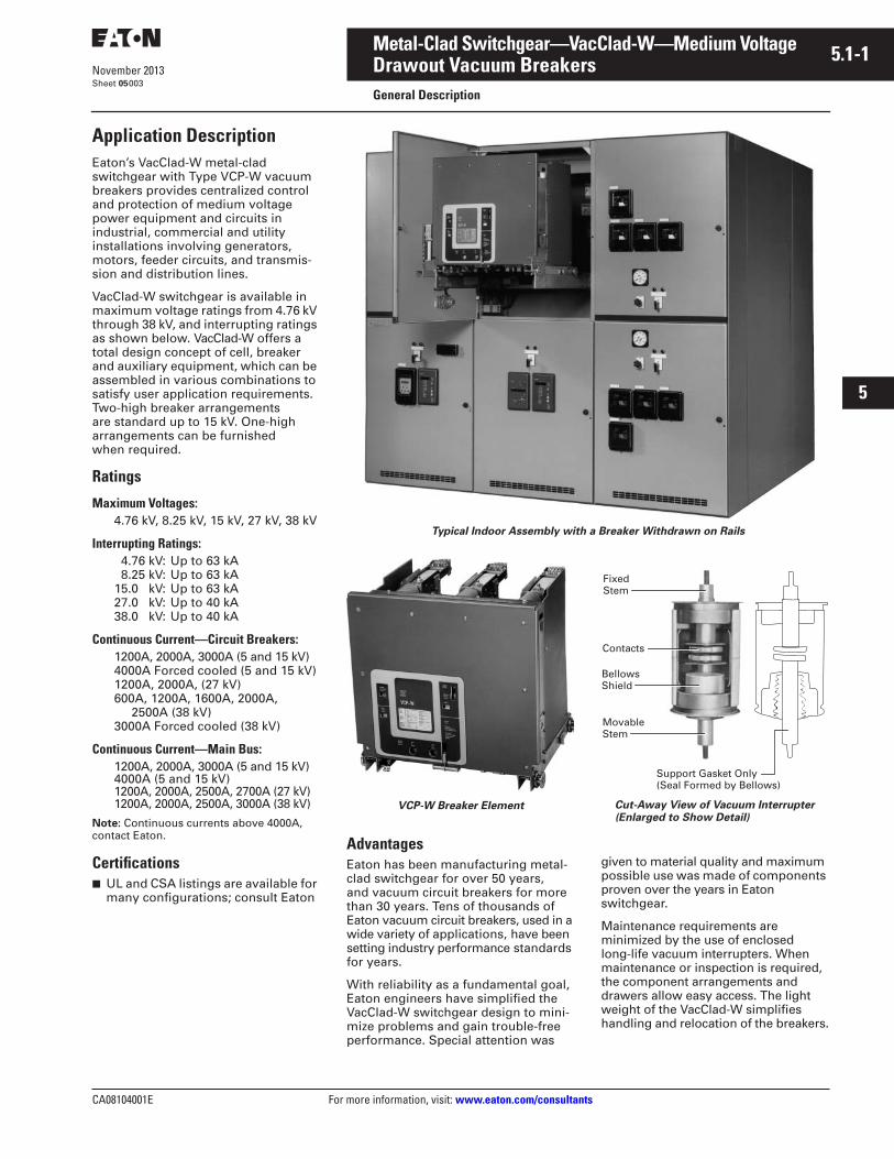
Eaton’s VacClad-W metal-clad switchgear with Type VCP-W vacuum breakers provides centralized control and protection of medium voltage power equipment and circuits in industrial, commercial and utility installations involving generators, motors, feeder circuits, and transmis-sion and distribution lines.
VacClad-W switchgear is available in maximum voltage ratings from 4.76 kV through 38 kV, and interrupting ratings as shown below. VacClad-W offers a total design concept of cell, breaker and auxiliary equipment, which can be assembled in various combinations to satisfy user application requirements. Two-high breaker arrangements are standard up to 15 kV. One-high arrangements can be furnished when required.
Ratings
Maximum Voltages:
4.76 kV, 8.25 kV, 15 kV, 27 kV, 38 kV
Interrupting Ratings:
4.76 kV: Up to 63 kA 8.25 kV: Up to 63 kA15.0 kV: Up to 63 kA27.0 kV: Up to 40 kA38.0 kV: Up to 40 kA
Continuous Current—Circuit Breakers:
1200A, 2000A, 3000A (5 and 15 kV)4000A Forced cooled (5 and 15 kV)1200A, 2000A, (27 kV)600A, 1200A, 1600A, 2000A,
2500A (38 kV)3000A Forced cooled (38 kV)
Continuous Current—Main Bus:
1200A, 2000A, 3000A (5 and 15 kV)4000A (5 and 15 kV)
1200A, 2000A, 2500A, 2700A (27 kV
)
1200A, 2000A, 2500A, 3000A (38 kV)
Note:
Continuous currents above 4000A, contact Eaton.
Certifications
■
UL and CSA listings are available for many configurations; consult Eaton
Typical Indoor Assembly with a Breaker Withdrawn on Rails
VCP-W Breaker Element
Advantages
Eaton has been manufacturing metal-clad switchgear for over 50 years, and vacuum circuit breakers for more than 30 years. Tens of thousands of Eaton vacuum
circuit breakers, used in a wide variety of
applications, have been setting industry performance standards for years.
With reliability as a fundamental goal, Eaton engineers have simplified the VacClad-W switchgear design to mini-mize problems and gain trouble-free performance. Special attention was
Cut-Away View of Vacuum Interrupter (Enlarged to Show Detail)
given to material quality and maximum possible use was made of components proven over the years in Eaton switchgear.
Maintenance requirements are minimized by the use of enclosed long-life vacuum interrupters. When maintenance or inspection is required, the component arrangements and drawers allow easy access. The light weight of the VacClad-W simplifies handling and relocation of the breakers.
FixedStem
Contacts
BellowsShield
Movable Stem
Support Gasket Only(Seal Formed by Bellows)
5.1-2
For more information, visit:
www.eaton.com/consultants
CA08104001E
November 2013
Metal-Clad Switchgear—VacClad-W—Medium Voltage
i
ii
1
2
3
4
5
6
7
8
9
10
11
12
13
14
15
16
17
18
19
20
21
Sheet
05
Drawout Vacuum Breakers
General Description
004
Standards
Eaton’s VacClad-W switchgear meets or exceeds ANSI/ IEEE C37.20.2 and NEMA
®
SG-5 as they apply to metal-clad switchgear. The assemblies also conform to Canadian standard CSA
®
-C22.2 No. 31-04, and EEMAC G8-3.2. Type VCP-W vacuum circuit breakers meet or exceed all ANSI and IEEE standards applicable to AC high voltage circuit breakers rated on symmetrical current basis.
Seismic Qualification
Refer to
Tab 1
for information on seismic qualification for this and other Eaton products.
Metal-Clad Switchgear Compartmentalization
Medium voltage metal-clad switchgear equipment conforming to C37.20.2 is a compartmentalized design, wherein primary conductors are fully insulated for the rated maximum voltage of the assembly, and all major primary circuitcomponents are isolated from each other by grounded metal barriers. This type of construction minimizes the likelihood of arcing faults within the equipment and propagation of fault between the compartments containing major primary circuits.
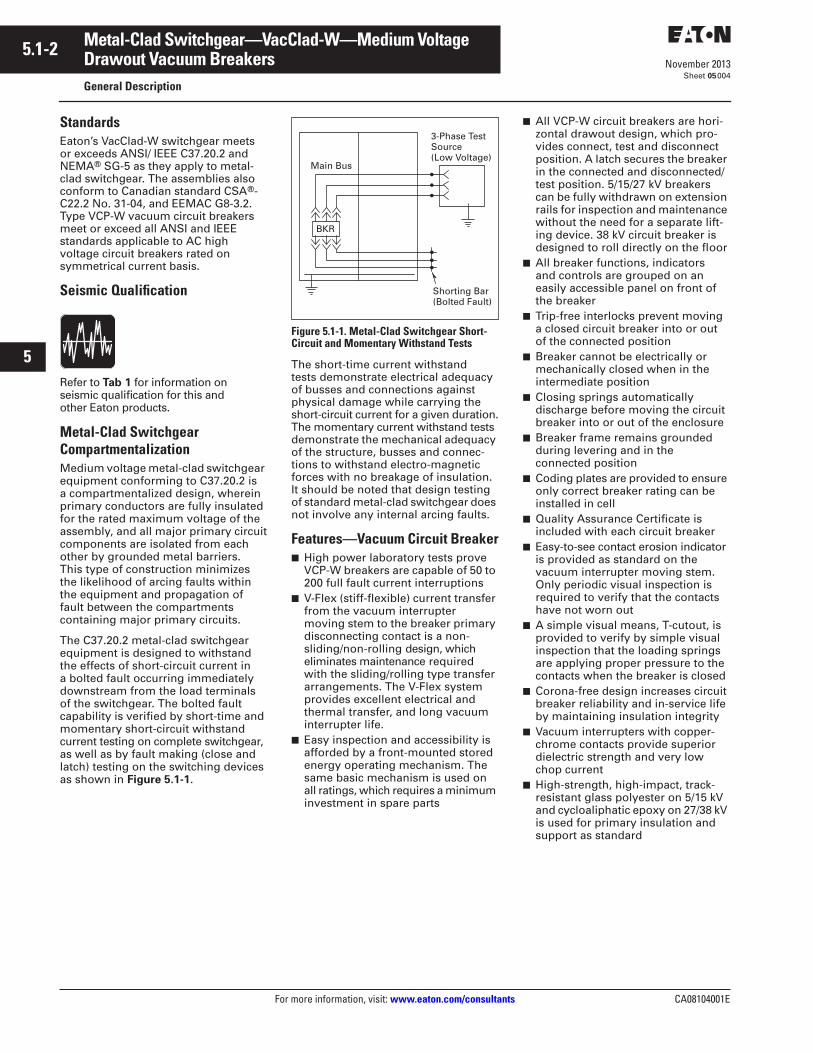
The C37.20.2 metal-clad switchgear equipment is designed to withstand the effects of short-circuit current in a bolted fault occurring immediately downstream from the load terminals of the switchgear. The bolted fault capability is verified by short-time and momentary short-circuit withstand current testing on complete switchgear, as well as by fault making (close and latch) testing on the switching devices as shown in
Figure 5.1-1
.
Figure 5.1-1. Metal-Clad Switchgear Short- Circuit and Momentary Withstand Tests
The short-time current withstand tests demonstrate electrical adequacy of busses and connections against physical damage while carrying the short-circuit current for a given duration.The momentary current withstand tests demonstrate the mechanical adequacy of the structure, busses and connec-tions to withstand electro-magnetic forces with no breakage of insulation. It should be noted that design testing of standard metal-clad switchgear does not involve any internal arcing faults.
Features—Vacuum Circuit Breaker
■
High power laboratory tests prove VCP-W breakers are capable of 50 to 200 full fault current interruptions
■
V-Flex (stiff-flexible) current transfer from the vacuum interrupter moving stem to the breaker primary disconnecting contact is a non-sliding/non-rolling design, which eliminates maintenance required with the sliding/rolling type transfer arrangements. The V-Flex system provides excellent electrical and thermal transfer, and long vacuum interrupter life.
■
Easy inspection and accessibility is afforded by a front-mounted stored energy operating mechanism. The same basic mechanism is used on all ratings, which requires a minimum investment in spare parts
■
All VCP-W circuit breakers are hori-zontal drawout design, which pro-vides connect, test and disconnect position. A latch secures the breaker in the connected and disconnected/test position. 5/15/27 kV breakers can be fully withdrawn on extension rails for inspection and maintenance without the need for a separate lift-ing device. 38 kV circuit breaker is designed to roll directly on the floor
■
All breaker functions, indicators and controls are grouped on an easily accessible panel on front of the breaker
■
Trip-free interlocks prevent moving a closed circuit breaker into or out of the connected position
■
Breaker cannot be electrically or mechanically closed when in the intermediate position
■
Closing springs automatically discharge before moving the circuit breaker into or out of the enclosure
■
Breaker frame remains grounded during levering and in the connected position
■
Coding plates are provided to ensure only correct breaker rating can be installed in cell
■
Quality Assurance Certificate is included with each circuit breaker
■
Easy-to-see contact erosion indicator is provided as standard on the vacuum interrupter moving stem. Only periodic visual inspection is required to verify that the contacts have not worn out
■
A simple visual means, T-cutout, is provided to verify by simple visual inspection that the loading springs are applying proper pressure to the contacts when the breaker is closed
■
Corona-free design increases circuit breaker reliability and in-service life by maintaining insulation integrity
■
Vacuum interrupters with copper-chrome contacts provide superior dielectric strength and very low chop current
■
High-strength, high-impact, track-resistant glass polyester on 5/15 kV and cycloaliphatic epoxy on 27/38 kV is used for primary insulation and support as standard
Main Bus
BKR
Shorting Bar(Bolted Fault)
3-Phase TestSource(Low Voltage)
CA08104001E For more information, visit:
www.eaton.com/consultants
5.1-3
November 2013
Metal-Clad Switchgear—VacClad-W—Medium Voltage
i
ii
1
2
3
4
5
6
7
8
9
10
11
12
13
14
15
16
17
18
19
20
21
Sheet
05
Drawout Vacuum Breakers
General Description
005
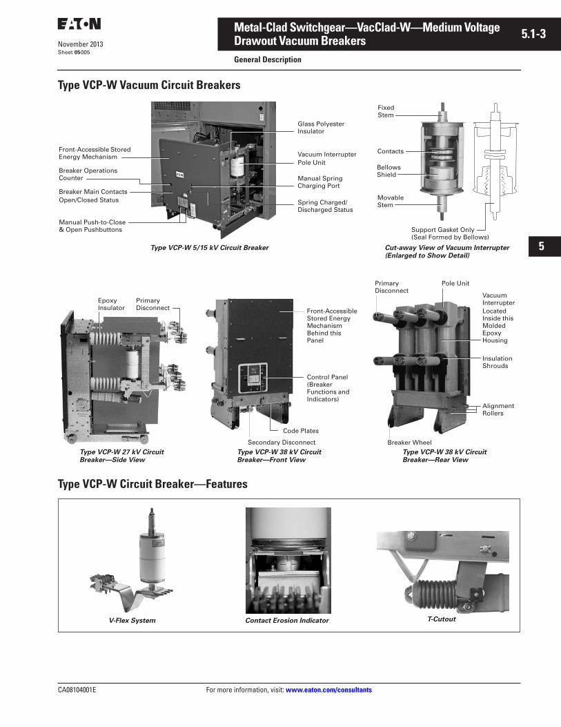
Type VCP-W Vacuum Circuit Breakers
Type VCP-W Circuit Breaker—Features
FixedStem
Contacts
BellowsShield
Movable Stem
Support Gasket Only(Seal Formed by Bellows)
Cut-away View of Vacuum Interrupter (Enlarged to Show Detail)
Breaker Main ContactsOpen/Closed Status
Vacuum InterrupterPole Unit
Front-Accessible Stored Energy Mechanism
Breaker OperationsCounter
Manual Push-to-Close & Open Pushbuttons
Manual SpringCharging Port
Spring Charged/Discharged Status
Type VCP-W 5/15 kV Circuit Breaker
Glass Polyester Insulator
Epoxy Insulator
PrimaryDisconnect
PrimaryDisconnect
Breaker Wheel
Pole Unit
Vacuum InterrupterLocated Inside this Molded EpoxyHousing
InsulationShrouds
AlignmentRollers
Type VCP-W 38 kV Circuit Breaker—Front View
Type VCP-W 27 kV Circuit Breaker—Side View
Type VCP-W 38 kV Circuit Breaker—Rear View
Front-AccessibleStored Energy Mechanism Behind this Panel
Code Plates
Secondary Disconnect
Control Panel (Breaker Functions and Indicators)
V-Flex System Contact Erosion Indicator T-Cutout
5.1-4
For more information, visit:
www.eaton.com/consultants
CA08104001E
November 2013
Metal-Clad Switchgear—VacClad-W—Medium Voltage
i
ii
1
2
3
4
5
6
7
8
9
10
11
12
13
14
15
16
17
18
19
20
21
Sheet
05
Drawout Vacuum Breakers—5 & 15 kV (36.00-Inch Wide)
General Description—Switchgear
006
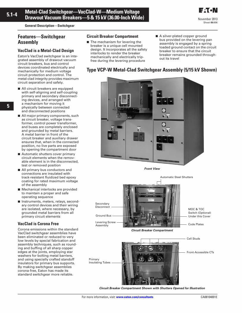
Features—Switchgear Assembly
VacClad is a Metal-Clad Design
Eaton’s VacClad switchgear is an inte-grated assembly of drawout vacuum circuit breakers, bus and control devices coordinated electrically and mechanically for medium voltage circuit protection and control. The metal-clad integrity provides maximum circuit separation and safety.
■
All circuit breakers are equipped with self-aligning and self-coupling primary and secondary disconnect-ing devices, and arranged with a mechanism for moving it physically between connected and disconnected positions
■
All major primary components, such as circuit breaker, voltage trans-former, control power transformer, and buses are completely enclosed and grounded by metal barriers. A metal barrier in front of the circuit breaker and auxiliary drawer ensures that, when in the connected position, no live parts are exposed by opening the compartment door
■
Automatic shutters cover primary circuit elements when the remov-able element is in the disconnected, test or removed position
■
All primary bus conductors and connections are insulated with track-resistant fluidized bed epoxy coating for rated maximum voltage of the assembly
■
Mechanical interlocks are provided to maintain a proper and safe operating sequence
■
Instruments, meters, relays, second-ary control devices and their wiring are isolated, where necessary, by grounded metal barriers from all primary circuit elements
VacClad is Corona Free
Corona emissions within the standard VacClad switchgear assemblies have been eliminated or reduced to very low levels by special fabrication and assembly techniques, such as round-ing and buffing of all sharp copper edges at the joints, employing star washers for bolting metal barriers, and using specially crafted standoff insulators for primary bus supports. By making switchgear assemblies corona-free, Eaton has made its standard switchgear more reliable.
Circuit Breaker Compartment
■
The mechanism for levering the breaker is a unique cell mounted design. It incorporates all the safety interlocks to render the breaker mechanically and electrically trip-free during the levering procedure
■
A silver-plated copper ground bus provided on the levering pan assembly is engaged by a spring loaded ground contact on the circuit breaker to ensure that the circuit breaker remains grounded through-out its travel
Type VCP-W Metal-Clad Switchgear Assembly (5/15 kV Shown)
Front View
Circuit Breaker Compartment
Circuit Breaker Compartment Shown with Shutters Opened for Illustration
MOC & TOCSwitch (Optional)Under this CoverGround Bus
Levering Screw Assembly Code Plates
Automatic Steel Shutters
Secondary Disconnect
Cell Studs
Front-Accessible CTs
Primary Insulating Tubes
CA08104001E For more information, visit:
www.eaton.com/consultants
5.1-5
November 2013
Metal-Clad Switchgear—VacClad-W—Medium Voltage
i
ii
1
2
3
4
5
6
7
8
9
10
11
12
13
14
15
16
17
18
19
20
21
Sheet
05
Drawout Vacuum Breakers—5 & 15 kV (36.00-Inch Wide)
General Description—Switchgear
007
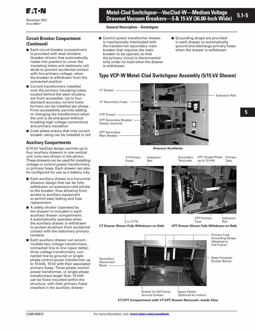
Circuit Breaker Compartment (Continued)
■
Each circuit breaker compartment is provided with steel shutters (breaker driven) that automatically rotate into position to cover the insulating tubes and stationary cell studs to prevent accidental contact with live primary voltage, when the breaker is withdrawn from the connected position
■
Current transformers installed over the primary insulating tubes, located behind the steel shutters, are front accessible. Up to four standard accuracy current trans-formers can be installed per phase. Front accessibility permits adding or changing the transformers when the unit is de-energized without breaking high voltage connections and primary insulation
■
Code plates ensure that only correct breaker rating can be installed in cell
Auxiliary Compartments
5/15 kV VacClad design permits up to four auxiliary drawers in one vertical unit (only two shown in the photo). These drawers can be used for installing voltage or control power transformers, or primary fuses. Each drawer can also be configured for use as a battery tray.
■
Each auxiliary drawer is a horizontal drawout design that can be fully withdrawn on extension rails similar to the breaker, thus allowing front access to auxiliary equipment to permit easy testing and fuse replacement
■
A safety shutter (operated by the drawer) is included in each auxiliary drawer compartment. It automatically operates whenthe auxiliary drawer is withdrawn to protect workmen from accidental contact with the stationary primary contacts
■
Each auxiliary drawer can accom-modate two voltage transformers, connected line-to-line (open delta); three voltage transformers, con-nected line-to-ground; or single-phase control power transformer up to 15 kVA, 15 kV with their associated primary fuses. Three-phase control power transformer, or single-phase transformers larger than 15 kVA can be fixed mounted within the structure, with their primary fuses installed in the auxiliary drawer
■
Control power transformer drawer is mechanically interlocked with the transformer secondary main breaker that requires the main breaker to be opened, so that the primary circuit is disconnected only under no-load when the drawer is withdrawn
■
Grounding straps are provided in each drawer to automatically ground and discharge primary fuses when the drawer is withdrawn
Type VCP-W Metal-Clad Switchgear Assembly (5/15 kV Shown)
Drawout Auxiliaries
VT Drawer Shown Fully Withdrawn on Rails CPT Drawer Shown Fully Withdrawn on Rails
VT/CPT Compartment with VT/CPT Drawer Removed—Inside View
VT Drawer
VT Secondary Fuses
CTP Drawer
CPT Secondary Breaker/Drawer Interlock
CPT Secondary Main Breaker
Extension Rail
2 or 3 VTs
VT Primary Fuses
Extension Rail
CPT Primary Fuse
Extension Rail
Primary Taps
Secondary Terminals
CPT, Single-Phase up to 15 kVA
Primary Fuse Grounding Straps (Attached to Cell Frame)
Glass Polyester Shutter Barrier
Space Heater (Optional for Indoor)
Secondary Disconnect Block
Drawer to Cell Frame Ground Contact
5.1-6
For more information, visit: www.eaton.com/consultants CA08104001E
November 2013
Metal-Clad Switchgear—VacClad-W—Medium Voltage
i
ii
1
2
3
4
5
6
7
8
9
10
11
12
13
14
15
16
17
18
19
20
21
Sheet 05
Drawout Vacuum Breakers—5 & 15 kV (36.00-Inch Wide)General Description—Switchgear
008
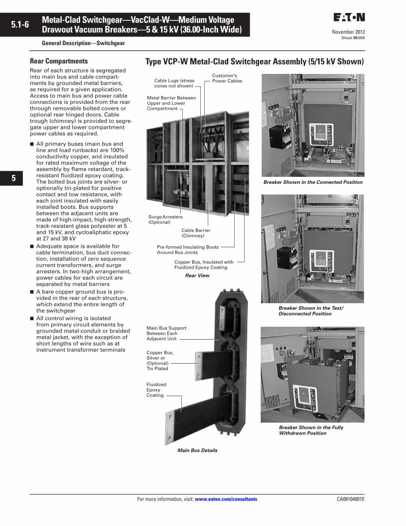
Rear CompartmentsRear of each structure is segregated into main bus and cable compart-ments by grounded metal barriers, as required for a given application. Access to main bus and power cable connections is provided from the rear through removable bolted covers or optional rear hinged doors. Cable trough (chimney) is provided to segre-gate upper and lower compartment power cables as required.
■ All primary buses (main bus and line and load runbacks) are 100% conductivity copper, and insulated for rated maximum voltage of the assembly by flame retardant, track-resistant fluidized epoxy coating. The bolted bus joints are silver- or optionally tin-plated for positive contact and low resistance, with each joint insulated with easily installed boots. Bus supports between the adjacent units are made of high-impact, high-strength, track-resistant glass polyester at 5 and 15 kV, and cycloaliphatic epoxy at 27 and 38 kV
■ Adequate space is available for cable termination, bus duct connec-tion, installation of zero sequence current transformers, and surge arresters. In two-high arrangement, power cables for each circuit are separated by metal barriers
■ A bare copper ground bus is pro-vided in the rear of each structure, which extend the entire length of the switchgear
■ All control wiring is isolated from primary circuit elements by grounded metal-conduit or braided metal jacket, with the exception of short lengths of wire such as at instrument transformer terminals
Type VCP-W Metal-Clad Switchgear Assembly (5/15 kV Shown)
Rear View
Main Bus Details
Breaker Shown in the Connected Position
Breaker Shown in the Test/Disconnected Position
Breaker Shown in the FullyWithdrawn Position
Copper Bus, Insulated withFluidized Epoxy Coating
Cable Lugs (stress cones not shown)
Customer’sPower Cables
Metal Barrier Between Upper and LowerCompartment
Cable Barrier(Chimney)
Pre-formed Insulating BootsAround Bus Joints
Surge Arresters (Optional)
Main Bus Support Between Each Adjacent Unit
Copper Bus, Silver or (Optional)Tin Plated
Fluidized Epoxy Coating
CA08104001E For more information, visit: www.eaton.com/consultants
5.1-7November 2013
Metal-Clad Switchgear—VacClad-W—Medium Voltage
i
ii
1
2
3
4
5
6
7
8
9
10
11
12
13
14
15
16
17
18
19
20
21
Sheet 05
Drawout Vacuum Breakers—5 & 15 kV (36.00-Inch Wide)General Description—Switchgear
009
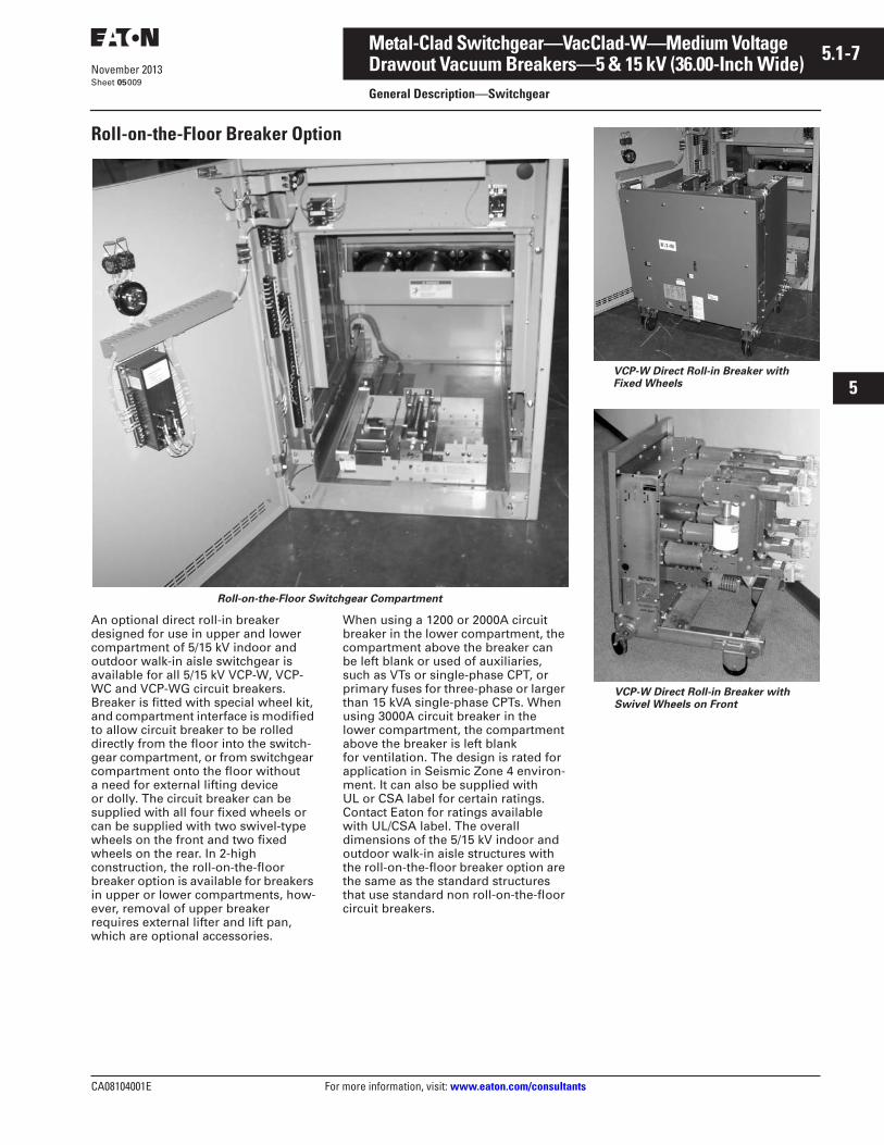
Roll-on-the-Floor Breaker Option
Roll-on-the-Floor Switchgear Compartment
An optional direct roll-in breaker designed for use in upper and lower compartment of 5/15 kV indoor and outdoor walk-in aisle switchgear is available for all 5/15 kV VCP-W, VCP-WC and VCP-WG circuit breakers. Breaker is fitted with special wheel kit, and compartment interface is modified to allow circuit breaker to be rolled directly from the floor into the switch-gear compartment, or from switchgear compartment onto the floor without a need for external lifting device or dolly. The circuit breaker can be supplied with all four fixed wheels or can be supplied with two swivel-type wheels on the front and two fixed wheels on the rear. In 2-high construction, the roll-on-the-floor breaker option is available for breakers in upper or lower compartments, how-ever, removal of upper breaker requires external lifter and lift pan, which are optional accessories.
When using a 1200 or 2000A circuit breaker in the lower compartment, the compartment above the breaker can be left blank or used of auxiliaries, such as VTs or single-phase CPT, or primary fuses for three-phase or larger than 15 kVA single-phase CPTs. When using 3000A circuit breaker in the lower compartment, the compartment above the breaker is left blank for ventilation. The design is rated for application in Seismic Zone 4 environ-ment. It can also be supplied with UL or CSA label for certain ratings. Contact Eaton for ratings available with UL/CSA label. The overall dimensions of the 5/15 kV indoor and outdoor walk-in aisle structures with the roll-on-the-floor breaker option are the same as the standard structures that use standard non roll-on-the-floor circuit breakers.
VCP-W Direct Roll-in Breaker withFixed Wheels
VCP-W Direct Roll-in Breaker withSwivel Wheels on Front
5.1-8
For more information, visit: www.eaton.com/consultants CA08104001E
November 2013
Metal-Clad Switchgear—VacClad-W—Medium Voltage
i
ii
1
2
3
4
5
6
7
8
9
10
11
12
13
14
15
16
17
18
19
20
21
Sheet 05
Drawout Vacuum Breakers—5 kV (26.00-Inch Wide)General Description
010
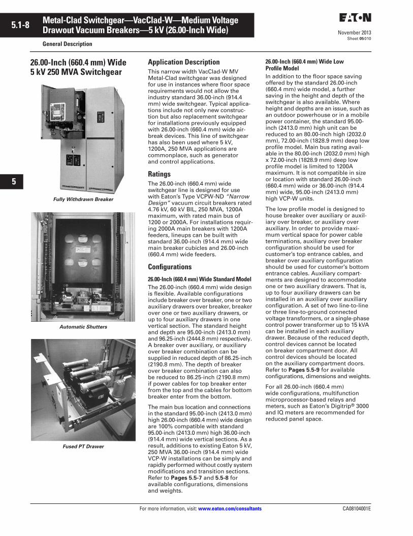
26.00-Inch (660.4 mm) Wide 5 kV 250 MVA Switchgear
Fully Withdrawn Breaker
Automatic Shutters
Fused PT Drawer
Application DescriptionThis narrow width VacClad-W MV Metal-Clad switchgear was designed for use in instances where floor space requirements would not allow the industry standard 36.00-inch (914.4 mm) wide switchgear. Typical applica-tions include not only new construc-tion but also replacement switchgear for installations previously equipped with 26.00-inch (660.4 mm) wide air-break devices. This line of switchgear has also been used where 5 kV, 1200A, 250 MVA applications are commonplace, such as generator and control applications.
RatingsThe 26.00-inch (660.4 mm) wide switchgear line is designed for use with Eaton’s Type VCPW-ND “Narrow Design” vacuum circuit breakers rated 4.76 kV, 60 kV BIL, 250 MVA, 1200A maximum, with rated main bus of 1200 or 2000A. For installations requir-ing 2000A main breakers with 1200A feeders, lineups can be built with standard 36.00-inch (914.4 mm) wide main breaker cubicles and 26.00-inch (660.4 mm) wide feeders.
Configurations
26.00-Inch (660.4 mm) Wide Standard ModelThe 26.00-inch (660.4 mm) wide design is flexible. Available configurations include breaker over breaker, one or two auxiliary drawers over breaker, breaker over one or two auxiliary drawers, or up to four auxiliary drawers in one vertical section. The standard height and depth are 95.00-inch (2413.0 mm) and 96.25-inch (2444.8 mm) respectively. A breaker over auxiliary, or auxiliary over breaker combination can be supplied in reduced depth of 86.25-inch (2190.8 mm). The depth of breaker over breaker combination can also be reduced to 86.25-inch (2190.8 mm) if power cables for top breaker enter from the top and the cables for bottom breaker enter from the bottom.
The main bus location and connections in the standard 95.00-inch (2413.0 mm) high 26.00-inch (660.4 mm) wide design are 100% compatible with standard 95.00-inch (2413.0 mm) high 36.00-inch (914.4 mm) wide vertical sections. As a result, additions to existing Eaton 5 kV, 250 MVA 36.00-inch (914.4 mm) wide VCP-W installations can be simply and rapidly performed without costly system modifications and transition sections. Refer to Pages 5.5-7 and 5.5-8 for available configurations, dimensions and weights.
26.00-Inch (660.4 mm) Wide Low Profile ModelIn addition to the floor space saving offered by the standard 26.00-inch (660.4 mm) wide model, a further saving in the height and depth of the switchgear is also available. Where height and depths are an issue, such as an outdoor powerhouse or in a mobile power container, the standard 95.00-inch (2413.0 mm) high unit can be reduced to an 80.00-inch high (2032.0 mm), 72.00-inch (1828.9 mm) deep low profile model. Main bus rating avail-able in the 80.00-inch (2032.0 mm) high x 72.00-inch (1828.9 mm) deep low profile model is limited to 1200A maximum. It is not compatible in size or location with standard 26.00-inch (660.4 mm) wide or 36.00-inch (914.4 mm) wide, 95.00-inch (2413.0 mm) high VCP-W units.
The low profile model is designed to house breaker over auxiliary or auxil-iary over breaker, or auxiliary over auxiliary. In order to provide maxi-mum vertical space for power cable terminations, auxiliary over breaker configuration should be used for customer’s top entrance cables, and breaker over auxiliary configuration should be used for customer’s bottom entrance cables. Auxiliary compart-ments are designed to accommodate one or two auxiliary drawers. That is, up to four auxiliary drawers can be installed in an auxiliary over auxiliary configuration. A set of two line-to-line or three line-to-ground connected voltage transformers, or a single-phase control power transformer up to 15 kVA can be installed in each auxiliary drawer. Because of the reduced depth, control devices cannot be located on breaker compartment door. All control devices should be located on the auxiliary compartment doors. Refer to Pages 5.5-9 for available configurations, dimensions and weights.
For all 26.00-inch (660.4 mm) wide configurations, multifunction microprocessor-based relays and meters, such as Eaton’s Digitrip® 3000 and IQ meters are recommended for reduced panel space.
CA08104001E For more information, visit: www.eaton.com/consultants
5.1-9November 2013
Metal-Clad Switchgear—VacClad-W—Medium Voltage
i
ii
1
2
3
4
5
6
7
8
9
10
11
12
13
14
15
16
17
18
19
20
21
Sheet 05
Drawout Vacuum Breakers—27 kV (36.00-Inch Wide)General Description
011
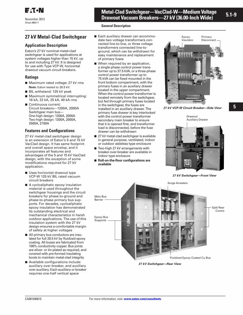
27 kV Metal-Clad Switchgear
Application DescriptionEaton’s 27 kV nominal metal-clad switchgear is used for applications at system voltages higher than 15 kV, up to and including 27 kV. It is designed for use with Type VCP-W, horizontal drawout vacuum circuit breakers.
Ratings■ Maximum rated voltage: 27 kV rms
Note: Eaton tested to 28.5 kV.■ BIL withstand: 125 kV peak■ Maximum symmetrical interrupting:
16 kA, 22 kA, 25 kA, 40 kA rms■ Continuous current:
Circuit breakers—1200A, 2000ASwitchgear main bus—One-high design: 1200A, 2000ATwo-high design: 1200A, 2000A, 2500A, 2700A
Features and Configurations27 kV metal-clad switchgear design is an extension of Eaton’s 5 and 15 kV VacClad design. It has same footprint and overall space envelop, and it incorporates all features and advantages of the 5 and 15 kV VacClad design, with the exception of some modifications required for 27 kV application.
■ Uses horizontal drawout type VCP-W 125 kV BIL rated vacuum circuit breakers
■ A cycloaliphatic epoxy insulation material is used throughout the switchgear housings and the circuit breakers for phase-to-ground and phase-to-phase primary bus sup-ports. For decades, cycloaliphatic epoxy insulation has demonstrated its outstanding electrical and mechanical characteristics in harsh outdoor applications. The use of this insulation system with the 27 kV design ensures a comfortable margin of safety at higher voltages
■ All primary bus conductors are insu-lated for full 28.5 kV by fluidized epoxy coating. All buses are fabricated from 100% conductivity copper. Bus joints are silver- or tin-plated as required, and covered with pre-formed insulating boots to maintain metal-clad integrity
■ Available configurations include: auxiliary over breaker, and auxiliary over auxiliary. Each auxiliary or breaker requires one-half vertical space
■ Each auxiliary drawer can accommo-date two voltage transformers con-nected line-to-line, or three voltage transformers connected line-to-ground, which can be withdrawn for easy maintenance and replacement of primary fuses
■ When required by an application, a single-phase control power trans-former up to 37.5 kVA, or a three-phase control power transformer up to 75 kVA can be fixed mounted in the front bottom compartment, with the primary fuses in an auxiliary drawer located in the upper compartment. When the control power transformer is located remotely from the switchgear, but fed through primary fuses located in the switchgear, the fuses are installed in an auxiliary drawer. The primary fuse drawer is key interlocked with the control power transformer secondary main breaker to ensure that it is opened first, and transformer load is disconnected, before the fuse drawer can be withdrawn
■ 27 kV metal-clad switchgear is available in general purpose, ventilated, indoor or outdoor aisleless type enclosure
■ Two-high 27 kV arrangements with breaker-over-breaker are available in indoor type enclosure
■ Roll-on-the-floor configurations are available
27 kV VCP-W Circuit Breaker—Side View
27 kV Switchgear—Front View
27 kV Switchgear—Rear View
Epoxy Insulator
PrimaryDisconnect
DrawoutAuxiliary Drawer
Main Bus Barrier
Surge Arresters
Epoxy Bus Supports
Fluidized Epoxy Coated Cu Bus
Split RearCovers
5.1-10
For more information, visit: www.eaton.com/consultants CA08104001E
November 2013
Metal-Clad Switchgear—VacClad-W—Medium Voltage
i
ii
1
2
3
4
5
6
7
8
9
10
11
12
13
14
15
16
17
18
19
20
21
Sheet 05
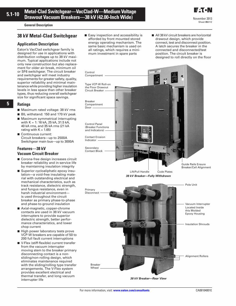
Drawout Vacuum Breakers—38 kV (42.00-Inch Wide)General Description
012
38 kV Metal-Clad Switchgear
Application DescriptionEaton’s VacClad switchgear family is designed for use in applications with distribution voltages up to 38 kV maxi-mum. Typical applications include not only new construction but also replace-ment for older air-break, minimum oil or SF6 switchgear. The circuit breaker and switchgear will meet industry requirements for greater safety, quality, superior reliability and minimal main-tenance while providing higher insulation levels in less space than other breaker types, thus reducing overall switchgear size for significant space savings.
Ratings■ Maximum rated voltage: 38 kV rms■ BIL withstand: 150 and 170 kV peak■ Maximum symmetrical interrupting
with K = 1: 16 kA, 25 kA, 31.5 kA, 40 kA rms, and 35 kA rms (21 kA rating with K = 1.65)
■ Continuous current:Circuit breakers—up to 2500ASwitchgear main bus—up to 3000A
Features—38 kVVacuum Circuit Breaker■ Corona-free design increases circuit
breaker reliability and in-service life by maintaining insulation integrity
■ Superior cycloaliphatic epoxy insu-lation—a void-free insulating mate-rial with outstanding electrical and mechanical characteristics, such as track resistance, dielectric strength, and fungus resistance, even in harsh industrial environment—is used throughout the circuit breaker as primary phase-to-phase and phase-to-ground insulation
■ Axial-magnetic, copper-chrome contacts are used in 38 kV vacuum interrupters to provide superior dielectric strength, better perfor-mance characteristics, and lower chop current
■ High power laboratory tests prove VCP-W breakers are capable of 50 to 200 full fault current interruptions
■ V-Flex (stiff-flexible) current transfer from the vacuum interrupter moving stem to the breaker primary disconnecting contact is a non-sliding/non-rolling design, which eliminates maintenance required with the sliding/rolling type transfer arrangements. The V-Flex system provides excellent electrical and thermal transfer, and long vacuum interrupter life
■ Easy inspection and accessibility is afforded by front mounted stored energy operating mechanism. The same basic mechanism is used on all ratings, which requires a mini-mum investment in spare parts
■ All 38 kV circuit breakers are horizontal drawout design, which provide connect, test and disconnect position. A latch secures the breaker in the connected and disconnected/test position. The circuit breaker is designed to roll directly on the floor
38 kV Breaker—Fully Withdrawn
38 kV Breaker—Rear View
Control Compartment
Type VCP-W Roll-on the Floor Drawout Circuit Breaker
Breaker Compartment Door
Control Panel (Breaker Functions and Indicators)
Secondary Contact Block
Lift/Pull Handle Code Plates
Guide Rails Ensure Breaker/Cell Alignment
Contact ErosionIndicator
PrimaryDisconnect
BreakerWheel
Pole Unit
Vacuum InterrupterLocated Inside this Molded Epoxy Housing
Insulation Shrouds
Alignment Rollers
CA08104001E For more information, visit: www.eaton.com/consultants
5.1-11November 2013
Metal-Clad Switchgear—VacClad-W—Medium Voltage
i
ii
1
2
3
4
5
6
7
8
9
10
11
12
13
14
15
16
17
18
19
20
21
Sheet 05
Drawout Vacuum Breakers—38 kV (42.00-Inch Wide)General Description—38 kV Switchgear
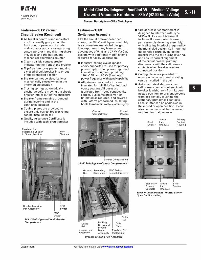
013
Features—38 kV Vacuum Circuit Breaker (Continued)■ All breaker controls and indicators
are functionally grouped on the front control panel and include: main contact status, closing spring status, port for manual spring charg-ing, close and trip button, and mechanical operations counter
■ Clearly visible contact erosion indicator on the front of the breaker
■ Trip-free interlocks prevent moving a closed circuit breaker into or out of the connected position
■ Breaker cannot be electrically or mechanically closed when in the intermediate position
■ Closing springs automatically discharge before moving the circuit breaker into or out of the enclosure
■ Breaker frame remains grounded during levering and in the connected position
■ Coding plates are provided to ensure only correct breaker rating can be installed in cell
■ Quality Assurance Certificate is included with each circuit breaker
38 kV Switchgear—Circuit Breaker Compartment
Provision for Padlocking Shutter in Closed Position
Breaker Levering Pan Assembly
TOC Switch
MOC Switch
Steel Shutters
Features—38 kV Switchgear AssemblyLike the circuit breaker described above, the 38 kV switchgear assembly is a corona-free metal-clad design. It incorporates many features and advantages of 5, 15 and 27 kV VacClad design, with additional modifications required for 38 kV application.
■ Industry-leading cycloaliphatic epoxy supports are used for primary phase-to-phase and phase-to-ground insulation throughout, providing 170 kV BIL and 80 kV (1 minute) power frequency withstand capability
■ All primary bus conductors are insulated for full 38 kV by fluidized epoxy coating. All buses are fabricated from 100% conductivity copper. Bus joints are silver- or tin-plated as required, and covered with Eaton’s pre-formed insulating boots to maintain metal-clad integrity
38 kV Switchgear—Control Compartment
Breaker Levering Pan Assembly
■ Circuit breaker compartment is designed to interface with Type VCP-W 38 kV circuit breaker. It includes floor-mounted breaker pan assembly (levering assembly) with all safety interlocks required by the metal-clad design. Cell mounted guide rails accurately guide the breaker into the cell during levering, and ensure correct alignment of the circuit breaker primary disconnects with the cell primary contacts when breaker reaches connected position
■ Coding plates are provided to ensure only correct breaker rating can be installed in the cell
■ Automatic steel shutters cover cell primary contacts when circuit breaker is withdrawn from its con-nected position, to prevent persons from accidentally touching the stationary primary cell contacts. Each shutter can be padlocked in the closed or open position. It can also be manually latched open as required for maintenance
Breaker Compartment (Shutter Shown Open for Illustration)
Control Compartment
Control Devices
Breaker Compartment
Ground Bus
Secondary Disconnect
Guide Rail
Breaker Pan Assembly
MOC Switch Beneath this Cover
Code Plates
Provision for Padlocking
Racking Screw and Moving Block Assembly
Guide Rail
Steel Shutter
Stationary Primary Contacts
Shutter Latch (Manual)
Primary Contact Housing
Shutter Latch (Manual)
Steel Shutter
5.1-12
For more information, visit: www.eaton.com/consultants CA08104001E
November 2013
Metal-Clad Switchgear—VacClad-W—Medium Voltage
i
ii
1
2
3
4
5
6
7
8
9
10
11
12
13
14
15
16
17
18
19
20
21
Sheet 05
Drawout Vacuum Breakers—38 kV (42.00-Inch Wide)General Description—38 kV Switchgear
014
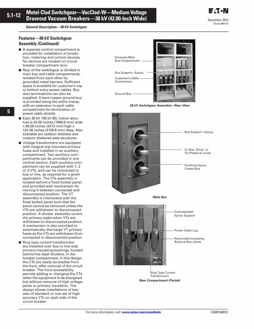
Features—38 kV Switchgear Assembly (Continued)■ A separate control compartment is
provided for installation of protec-tion, metering and control devices. No devices are located on circuit breaker compartment door
■ Rear of the switchgear is divided in main bus and cable compartments, isolated from each other by grounded metal barriers. Sufficient space is available for customer’s top or bottom entry power cables. Bus duct terminations can also be supplied. A bare copper ground bus is provided along the entire lineup, with an extension in each cable compartment for termination of power cable shields
■ Each 38 kV 150 kV BIL indoor struc-ture is 42.00 inches (1066.8 mm) wide x 95.00 inches (2413 mm) high x 124.36 inches (3158.8 mm) deep. Also available are outdoor aisleless and outdoor sheltered aisle structures
■ Voltage transformers are equipped with integral top-mounted primary fuses and installed in an auxiliary compartment. Two auxiliary com-partments can be provided in one vertical section. Each auxiliary com-partment can be supplied with 1, 2 or 3 VTs, and can be connected to bus or line, as required for a given application. The VTs assembly is located behind a fixed bolted panel, and provided with mechanism for moving it between connected and disconnected position. The VT assembly is interlocked with the fixed bolted panel such that the panel cannot be removed unless the VTs are withdrawn to disconnected position. A shutter assembly covers the primary stabs when VTs are withdrawn to disconnected position. A mechanism is also provided to automatically discharge VT primary fuses as the VTs are withdrawn from connected to disconnected position
■ Ring type current transformers are installed over bus or line side primary insulating bushings, located behind the steel shutters, in the breaker compartment. In this design, the CTs are easily accessible from the front, after removal of the circuit breaker. The front accessibility permits adding or changing the CTs when the equipment is de-energized, but without removal of high voltage joints or primary insulation. The design allows installations of two sets of standard or one set of high accuracy CTs on each side of the circuit breaker
38 kV Switchgear Assembly—Rear View
Main Bus
Rear Compartment (Partial)
Enclosed Main Bus Compartment
Bus Support—Epoxy
Customer’s Cable Connections
Ground Bus
Bus Support—Epoxy
Fluidized Epoxy Coated Bus
Cu Bus, Silver- or Tin-Plated at Joints
CycloaliphaticEpoxy Support
Power Cable Lug
Removable Insulating Boots at Bus Joints
Ring Type Current Transformers
CA08104001E For more information, visit: www.eaton.com/consultants
5.1-13November 2013
Metal-Clad Switchgear—VacClad-W—Medium Voltage
i
ii
1
2
3
4
5
6
7
8
9
10
11
12
13
14
15
16
17
18
19
20
21
Sheet 05
Drawout Vacuum Breakers—38 kV (42.00-Inch Wide)General Description—38 kV Switchgear
015
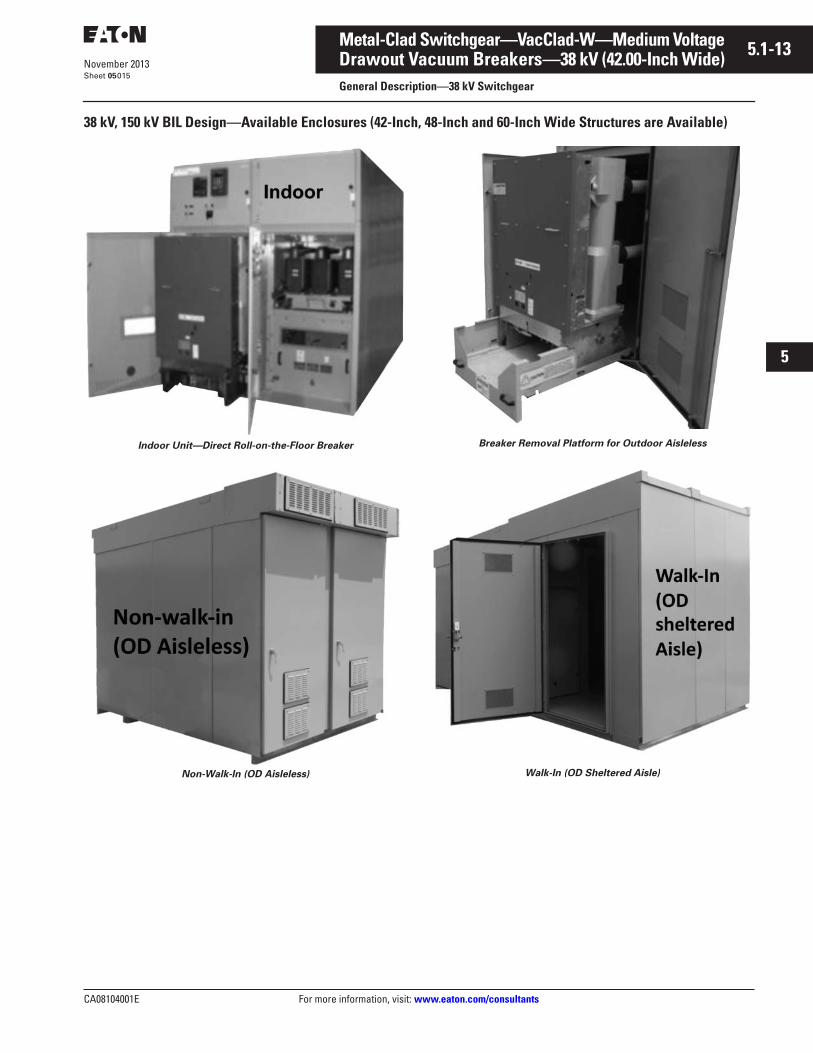
38 kV, 150 kV BIL Design—Available Enclosures (42-Inch, 48-Inch and 60-Inch Wide Structures are Available)
Indoor Unit—Direct Roll-on-the-Floor Breaker
Non-Walk-In (OD Aisleless)
Breaker Removal Platform for Outdoor Aisleless
Walk-In (OD Sheltered Aisle)

5.1-14
For more information, visit: www.eaton.com/consultants CA08104001E
November 2013
Metal-Clad Switchgear—VacClad-W—Medium Voltage
i
ii
1
2
3
4
5
6
7
8
9
10
11
12
13
14
15
16
17
18
19
20
21
Sheet 05016
This page intentionally left blank.
CA08104001E For more information, visit: www.eaton.com/consultants
5.2-1November 2013
Metal-Clad Switchgear—VacClad-W—Medium Voltage
i
ii
1
2
3
4
5
6
7
8
9
10
11
12
13
14
15
16
17
18
19
20
21
Sheet 05
Arc-Resistant SwitchgearGeneral Description
017
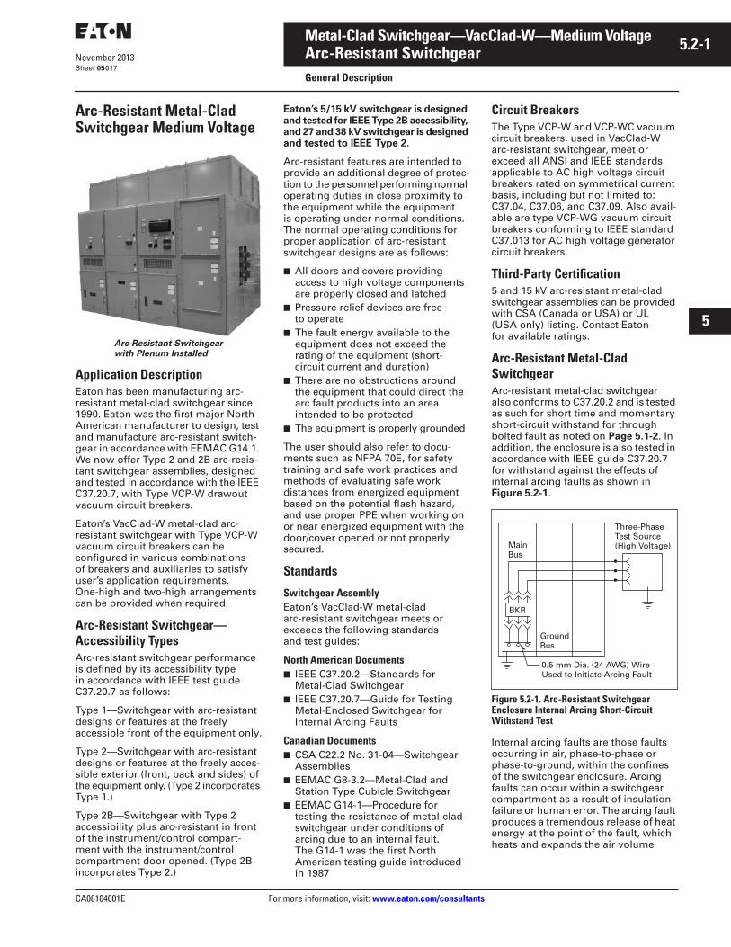
Arc-Resistant Metal-Clad Switchgear Medium Voltage
Arc-Resistant Switchgearwith Plenum Installed
Application DescriptionEaton has been manufacturing arc-resistant metal-clad switchgear since 1990. Eaton was the first major North American manufacturer to design, test and manufacture arc-resistant switch-gear in accordance with EEMAC G14.1. We now offer Type 2 and 2B arc-resis-tant switchgear assemblies, designed and tested in accordance with the IEEE C37.20.7, with Type VCP-W drawout vacuum circuit breakers.
Eaton’s VacClad-W metal-clad arc-resistant switchgear with Type VCP-W vacuum circuit breakers can be configured in various combinations of breakers and auxiliaries to satisfy user’s application requirements. One-high and two-high arrangements can be provided when required.
Arc-Resistant Switchgear—Accessibility TypesArc-resistant switchgear performance is defined by its accessibility type in accordance with IEEE test guide C37.20.7 as follows:
Type 1—Switchgear with arc-resistant designs or features at the freely accessible front of the equipment only.
Type 2—Switchgear with arc-resistant designs or features at the freely acces-sible exterior (front, back and sides) of the equipment only. (Type 2 incorporates Type 1.)
Type 2B—Switchgear with Type 2 accessibility plus arc-resistant in front of the instrument/control compart-ment with the instrument/control compartment door opened. (Type 2B incorporates Type 2.)
Eaton’s 5/15 kV switchgear is designed and tested for IEEE Type 2B accessibility, and 27 and 38 kV switchgear is designed and tested to IEEE Type 2.
Arc-resistant features are intended to provide an additional degree of protec-tion to the personnel performing normal operating duties in close proximity to the equipment while the equipment is operating under normal conditions. The normal operating conditions for proper application of arc-resistant switchgear designs are as follows:
■ All doors and covers providing access to high voltage components are properly closed and latched
■ Pressure relief devices are free to operate
■ The fault energy available to the equipment does not exceed the rating of the equipment (short-circuit current and duration)
■ There are no obstructions around the equipment that could direct the arc fault products into an area intended to be protected
■ The equipment is properly grounded
The user should also refer to docu-ments such as NFPA 70E, for safety training and safe work practices and methods of evaluating safe work distances from energized equipment based on the potential flash hazard, and use proper PPE when working on or near energized equipment with the door/cover opened or not properly secured.
Standards
Switchgear AssemblyEaton’s VacClad-W metal-clad arc-resistant switchgear meets or exceeds the following standards and test guides:
North American Documents■ IEEE C37.20.2—Standards for
Metal-Clad Switchgear■ IEEE C37.20.7—Guide for Testing
Metal-Enclosed Switchgear for Internal Arcing Faults
Canadian Documents■ CSA C22.2 No. 31-04—Switchgear
Assemblies■ EEMAC G8-3.2—Metal-Clad and
Station Type Cubicle Switchgear■ EEMAC G14-1—Procedure for
testing the resistance of metal-clad switchgear under conditions of arcing due to an internal fault. The G14-1 was the first North American testing guide introduced in 1987
Circuit BreakersThe Type VCP-W and VCP-WC vacuum circuit breakers, used in VacClad-W arc-resistant switchgear, meet or exceed all ANSI and IEEE standards applicable to AC high voltage circuit breakers rated on symmetrical current basis, including but not limited to: C37.04, C37.06, and C37.09. Also avail-able are type VCP-WG vacuum circuit breakers conforming to IEEE standard C37.013 for AC high voltage generator circuit breakers.
Third-Party Certification5 and 15 kV arc-resistant metal-clad switchgear assemblies can be provided with CSA (Canada or USA) or UL (USA only) listing. Contact Eaton for available ratings.
Arc-Resistant Metal-Clad SwitchgearArc-resistant metal-clad switchgear also conforms to C37.20.2 and is tested as such for short time and momentary short-circuit withstand for through bolted fault as noted on Page 5.1-2. In addition, the enclosure is also tested in accordance with IEEE guide C37.20.7 for withstand against the effects of internal arcing faults as shown in Figure 5.2-1.
Figure 5.2-1. Arc-Resistant Switchgear Enclosure Internal Arcing Short-Circuit Withstand Test
Internal arcing faults are those faults occurring in air, phase-to-phase or phase-to-ground, within the confines of the switchgear enclosure. Arcing faults can occur within a switchgear compartment as a result of insulation failure or human error. The arcing fault produces a tremendous release of heat energy at the point of the fault, which heats and expands the air volume
MainBus
BKR
0.5 mm Dia. (24 AWG) WireUsed to Initiate Arcing Fault
Three-Phase Test Source(High Voltage)
GroundBus
5.2-2
For more information, visit: www.eaton.com/consultants CA08104001E
November 2013
Metal-Clad Switchgear—VacClad-W—Medium Voltage
i
ii
1
2
3
4
5
6
7
8
9
10
11
12
13
14
15
16
17
18
19
20
21
Sheet 05
Arc-Resistant SwitchgearGeneral Description
018
within the enclosure, and may decom-pose or vaporize materials exposed to an arc or involved in its path. The effects of this type of fault vary depending on enclosure volume, arc duration, arc voltage, and available short-circuit current. If the switchgear is not designed and tested to with-stand effects of internal arcing faults, its parts could blow away along with discharge of hot decomposed matter, gaseous or particulate, causing injury to personnel that may be present in its vicinity. Arc-resistant switchgear is designed to channel and control effects of the arcing fault and its enclosure is tested for withstand against such fault in accordance with IEEE guide C37.20.7.
Medium Voltage Vacuum Circuit Breaker Features and RatingsVacClad-W metal-clad arc-resistant switchgear is designed for use with Eaton’s state-of-the-art medium volt-age vacuum type VCP-W (standard ANSI), VCP-WC (extra capability), and VCP-WG (generator) circuit breakers. Refer to Tables 5.4-1B, 5.4-2 and 5.4-3 for complete list of available ratings.
Arc-Resistant Enclosure and Arc ExhaustVacClad-W arc-resistant switchgear is designed to withstand effects of inter-nal arcing faults up to its rated arc short-circuit current and duration. The arc-withstand capability of the switch-gear enclosure is achieved by use of reinforced heavier gauge steel where needed, smart latching of doors and covers, and top-mounted built-in pres-sure relief system. Following are stan-dard design features built into each arc-resistant switchgear assembly.
■ The formed steel compartment design provides sealed joints under fault conditions. This prevents smoke and gas from escaping to other compartments, a condition that can occur with switchgear compartments designed with conventional flat bolted panels
■ Integral, pressure release flap vents mounted on top of each individual vertical section provide for controlled upward release of arc created over-pressure, fire, smoke, gases and molten material out of the assembly without affecting structural integrity, and protect personnel who might be present in the vicinity of the switchgear
■ The structure roof, including the pressure release flap vents, is drip proof. The design is made strong such that the roof can be “walked-on” when the gear is completely de-energized (for example, during installation)
■ Since arc pressure is vented out through the top of each individual vertical section, the equipment damage is confined to individual structures, minimizing damage to adjacent structures
Circuit Breaker Compartment■ The levering mechanism is mechan-
ically interlocked with the compart-ment door such that the door cannot be opened until the circuit breaker is opened and levered out to the test/disconnect position. This interlock-ing ensures that the levering of the circuit breaker into or out from the connected position is done with compartment door closed and latched, with no exposure to potential arc flash
■ Easy access and viewing ports are provided on the door to allow oper-ator to carry out all normal functions with the door closed and latched, with no exposure to potential arc flash. Those functions include:Breaker levering, manual charging of closing springs, manual opening and closing of the circuit breaker, viewing of open/close status of the breaker main contacts, viewing of charged/discharged status of the closing springs, viewing of mechanical operations counter, and breaker position
Auxiliary CompartmentsVacClad arc-resistant 5/15 and 38 kV designs permit maximum of two auxil-iary drawers in one vertical section. The 27 kV design permits maximum of only one auxiliary drawer per vertical section.
■ Each auxiliary drawer is equipped with cell-mounted levering mecha-nism. The mechanism is mechanically interlocked with its compartment door such that the door cannot be opened and access to auxiliary drawer cannot be gained until the drawer is first levered out to the dis-connected position. This interlocking ensures that the levering of the auxiliary drawer into or out from the connected position is done with compartment door closed and latched, with no exposure to potential arc flash
■ A viewing window is provided on the door and on front panel of the drawer to allow viewing of the drawer position and the primary fuses
■ In 5/15 kV designs, each auxiliary drawer can also accommodate a single-phase CPT rated up to 15 kVA, with primary fuses, or the drawer can also be configured as a fuse drawer with two or three primary fuses, and connected to a fixed mounted CPT (single-phase or three-phase 45 kVA maximum) in the rear of the structure
■ In 27 kV designs, an auxiliary drawer can be configured as a fuse drawer with two primary fuses and con-nected to a fixed-mounted CPT (single-phase 25 kVA maximum) in the rear of the structure
■ In 38 kV designs, fuse drawer can be provided with two primary fuses and connected to a fixed-mounted CPT (single-phase 25 kVA maximum) in the rear of the structure. Please note that in 38 kV designs, a fuse drawer requires a full vertical section, because it occupies the same compartment space as required for a circuit breaker
Control CompartmentsThe control compartment doors can be opened to access control wiring without having to de-energize the pri-mary circuit. The control compartments have been tested to provide arc-resistant protection with its door opened under normal operating condition. Please note the control compartment door should be opened only for access to control wiring when needed, and should remain closed at all other times.
Relay Box on Breaker Compartment Door in 5/15 kV SwitchgearWhen needed for additional relays/instruments/controls, a relay box mounted on the breaker compartment door provides ample space for individ-ual breaker relaying and controls. An access to control wiring or device terminals that are enclosed within the relay box does not require opening of the circuit breaker compartment door.
Arc Exhaust Wall and Arc Exhaust Chamber (Plenum)Refer to Page 5.5-37.
CA08104001E For more information, visit: www.eaton.com/consultants
5.2-3November 2013
Metal-Clad Switchgear—VacClad-W—Medium Voltage
i
ii
1
2
3
4
5
6
7
8
9
10
11
12
13
14
15
16
17
18
19
20
21
Sheet 05
Arc-Resistant SwitchgearGeneral Description
019
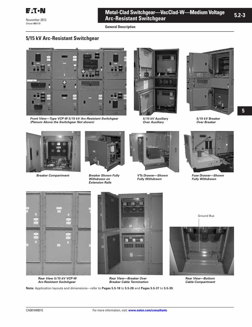
5/15 kV Arc-Resistant Switchgear
Note: Application layouts and dimensions—refer to Pages 5.5-18 to 5.5-28 and Pages 5.5-37 to 5.5-39.
Front View—Type VCP-W 5/15 kV Arc-Resistant Switchgear (Plenum Above the Switchgear Not shown)
5/15 kV Auxiliary Over Auxiliary
5/15 kV Breaker Over Breaker
Breaker Compartment Breaker Shown Fully Withdrawn on Extension Rails
VTs Drawer—Shown Fully Withdrawn
Fuse Drawer—Shown Fully Withdrawn
Rear View 5/15 kV VCP-W Arc-Resistant Switchgear
Rear View—Breaker Over Breaker Cable Termination
Rear View—Bottom Cable Compartment
Ground Bus
5.2-4
For more information, visit: www.eaton.com/consultants CA08104001E
November 2013
Metal-Clad Switchgear—VacClad-W—Medium Voltage
i
ii
1
2
3
4
5
6
7
8
9
10
11
12
13
14
15
16
17
18
19
20
21
Sheet 05
Arc-Resistant SwitchgearGeneral Description
020
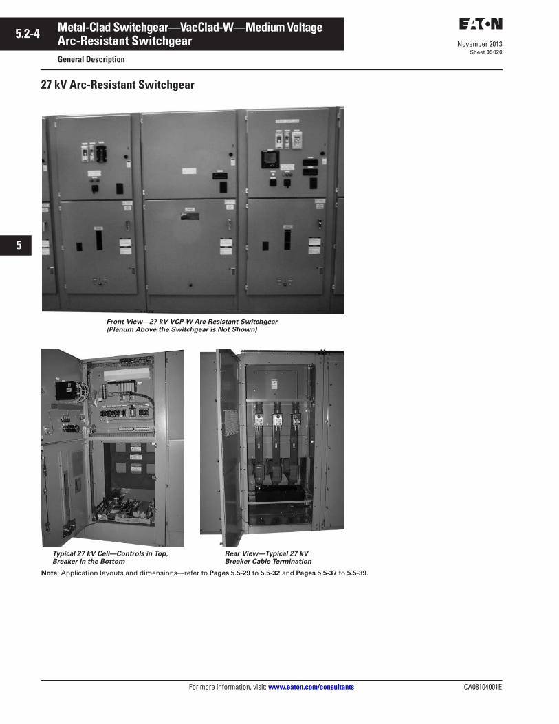
27 kV Arc-Resistant Switchgear
Note: Application layouts and dimensions—refer to Pages 5.5-29 to 5.5-32 and Pages 5.5-37 to 5.5-39.
Rear View—Typical 27 kV Breaker Cable Termination
Front View—27 kV VCP-W Arc-Resistant Switchgear (Plenum Above the Switchgear is Not Shown)
Typical 27 kV Cell—Controls in Top, Breaker in the Bottom
CA08104001E For more information, visit: www.eaton.com/consultants
5.2-5November 2013
Metal-Clad Switchgear—VacClad-W—Medium Voltage
i
ii
1
2
3
4
5
6
7
8
9
10
11
12
13
14
15
16
17
18
19
20
21
Sheet 05
Arc-Resistant SwitchgearGeneral Description
021
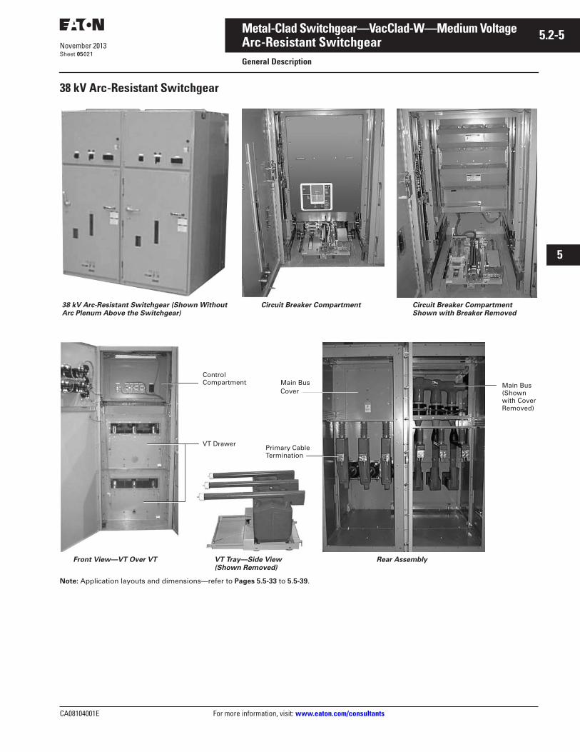
38 kV Arc-Resistant Switchgear
Note: Application layouts and dimensions—refer to Pages 5.5-33 to 5.5-39.
38 kV Arc-Resistant Switchgear (Shown Without Arc Plenum Above the Switchgear)
Circuit Breaker Compartment Circuit Breaker Compartment Shown with Breaker Removed
Front View—VT Over VT VT Tray—Side View (Shown Removed)
Rear Assembly
Control Compartment
VT Drawer
Main Bus Cover
Primary Cable Termination
Main Bus (Shown with Cover Removed)

5.2-6
For more information, visit: www.eaton.com/consultants CA08104001E
November 2013
Metal-Clad Switchgear—VacClad-W—Medium Voltage
i
ii
1
2
3
4
5
6
7
8
9
10
11
12
13
14
15
16
17
18
19
20
21
Sheet 05022
This page intentionally left blank.
CA08104001E For more information, visit: www.eaton.com/consultants
5.3-1November 2013
Metal-Clad Switchgear—VacClad-W—Medium Voltage
i
ii
1
2
3
4
5
6
7
8
9
10
11
12
13
14
15
16
17
18
19
20
21
Sheet 05
Partial DischargeGeneral Description
023
Partial Discharge Sensing and Monitoring for Switchgear
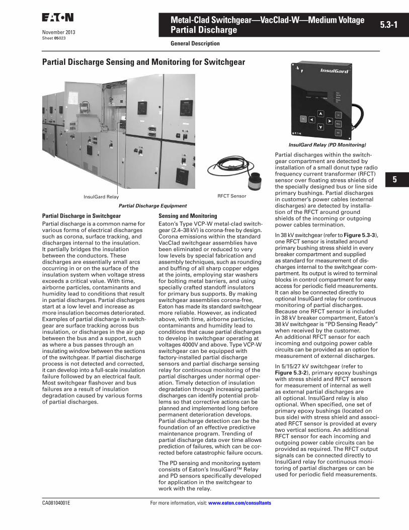
Partial Discharge Equipment
Partial Discharge in SwitchgearPartial discharge is a common name for various forms of electrical discharges such as corona, surface tracking, and discharges internal to the insulation. It partially bridges the insulation between the conductors. These discharges are essentially small arcs occurring in or on the surface of the insulation system when voltage stress exceeds a critical value. With time, airborne particles, contaminants and humidity lead to conditions that result in partial discharges. Partial discharges start at a low level and increase as more insulation becomes deteriorated. Examples of partial discharge in switch-gear are surface tracking across bus insulation, or discharges in the air gap between the bus and a support, such as where a bus passes through an insulating window between the sections of the switchgear. If partial discharge process is not detected and corrected, it can develop into a full-scale insulation failure followed by an electrical fault. Most switchgear flashover and bus failures are a result of insulation degradation caused by various forms of partial discharges.
Sensing and MonitoringEaton’s Type VCP-W metal-clad switch-gear (2.4–38 kV) is corona-free by design. Corona emissions within the standard VacClad switchgear assemblies have been eliminated or reduced to very low levels by special fabrication and assembly techniques, such as rounding and buffing of all sharp copper edges at the joints, employing star washers for bolting metal barriers, and using specially crafted standoff insulators for primary bus supports. By making switchgear assemblies corona-free, Eaton has made its standard switchgear more reliable. However, as indicated above, with time, airborne particles, contaminants and humidity lead to conditions that cause partial discharges to develop in switchgear operating at voltages 4000V and above. Type VCP-W switchgear can be equipped with factory-installed partial discharge sensors and partial discharge sensing relay for continuous monitoring of the partial discharges under normal oper-ation. Timely detection of insulation degradation through increasing partial discharges can identify potential prob-lems so that corrective actions can be planned and implemented long before permanent deterioration develops. Partial discharge detection can be the foundation of an effective predictive maintenance program. Trending of partial discharge data over time allows prediction of failures, which can be cor-rected before catastrophic failure occurs.
The PD sensing and monitoring system consists of Eaton’s InsulGard™ Relay and PD sensors specifically developed for application in the switchgear to work with the relay.
RFCT SensorInsulGard Relay
InsulGard Relay (PD Monitoring)
Partial discharges within the switch-gear compartment are detected by installation of a small donut type radio frequency current transformer (RFCT) sensor over floating stress shields of the specially designed bus or line side primary bushings. Partial discharges in customer’s power cables (external discharges) are detected by installa-tion of the RFCT around ground shields of the incoming or outgoing power cables termination.
In 38 kV switchgear (refer to Figure 5.3-3), one RFCT sensor is installed around primary bushing stress shield in every breaker compartment and supplied as standard for measurement of dis-charges internal to the switchgear com-partment. Its output is wired to terminal blocks in control compartment for easy access for periodic field measurements. It can also be connected directly to optional InsulGard relay for continuous monitoring of partial discharges. Because one RFCT sensor is included in 38 kV breaker compartment, Eaton’s 38 kV switchgear is “PD Sensing Ready” when received by the customer. An additional RFCT sensor for each incoming and outgoing power cable circuits can be provided as an option for measurement of external discharges.
In 5/15/27 kV switchgear (refer to Figure 5.3-2), primary epoxy bushings with stress shield and RFCT sensors for measurement of internal as well as external partial discharges are all optional. InsulGard relay is also optional. When specified, one set of primary epoxy bushings (located on bus side) with stress shield and associ-ated RFCT sensor is provided at every two vertical sections. An additional RFCT sensor for each incoming and outgoing power cable circuits can be provided as required. The RFCT output signals can be connected directly to InsulGard relay for continuous moni-toring of partial discharges or can be used for periodic field measurements.
5.3-2
For more information, visit: www.eaton.com/consultants CA08104001E
November 2013
Metal-Clad Switchgear—VacClad-W—Medium Voltage
i
ii
1
2
3
4
5
6
7
8
9
10
11
12
13
14
15
16
17
18
19
20
21
Sheet 05
Partial DischargeGeneral Description—Partial Discharge Sensing and Monitoring
024
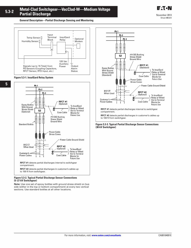
Figure 5.3-1. InsulGard Relay System
Figure 5.3-2. Typical Partial Discharge Sensor Connections (5–27 kV Switchgear)Note: Use one set of epoxy bottles with ground stress shield on bus side (either in the top or bottom compartment) at every two vertical sections. Use standard bottles at all other locations.
Figure 5.3-3. Typical Partial Discharge Sensor Connections (38 kV Switchgear)
InputTerminalBlock
InsulGardRelay Optional
Modem
Temp Sensor
Humidity Sensor
OutputAlarmStatus
120 VacAuxiliaryPowerSignals (up to 15 Total) from
PD Sensors (Coupling Capacitors,RFCT Sensor, RTD Input, etc.)
RFCT #1 detects partial discharges internal to switchgear compartment.
RFCT #2 detects partial discharges in customer’s cables up to 100 ft from switchgear.
RFCT #1 detects partial discharges internal to switchgear compartment.
RFCT #2 detects partial discharges in customer’s cables up to 100 ft from switchgear.
CA08104001E For more information, visit: www.eaton.com/consultants
5.3-3November 2013
Metal-Clad Switchgear—VacClad-W—Medium Voltage
i
ii
1
2
3
4
5
6
7
8
9
10
11
12
13
14
15
16
17
18
19
20
21
Sheet 05
Partial DischargeGeneral Description—Partial Discharge Sensing and Monitoring
025
Partial Discharge Sensors and Monitoring for Switchgear
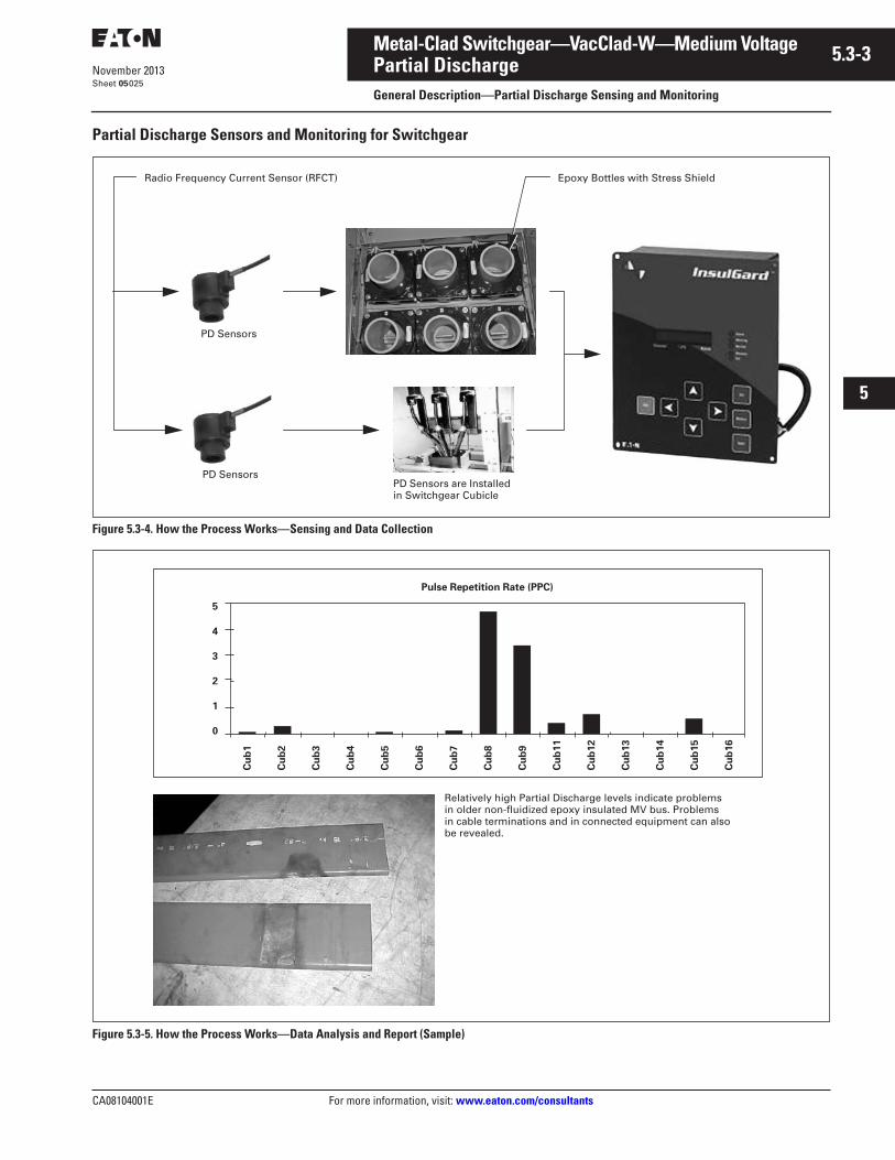
Figure 5.3-4. How the Process Works—Sensing and Data Collection
Figure 5.3-5. How the Process Works—Data Analysis and Report (Sample)
Radio Frequency Current Sensor (RFCT)
PD SensorsPD Sensors are Installed in Switchgear Cubicle
PD Sensors
Epoxy Bottles with Stress Shield
Relatively high Partial Discharge levels indicate problems in older non-fluidized epoxy insulated MV bus. Problems in cable terminations and in connected equipment can also be revealed.
Pulse Repetition Rate (PPC)
5
4
3
2
1
0
Cu
b1
Cu
b2
Cu
b3
Cu
b4
Cu
b5
Cu
b6
Cu
b7
Cu
b8
Cu
b9
Cu
b11
Cu
b12
Cu
b13
Cu
b14
Cu
b15
Cu
b16
5.3-4
For more information, visit: www.eaton.com/consultants CA08104001E
November 2013
Metal-Clad Switchgear—VacClad-W—Medium Voltage
i
ii
1
2
3
4
5
6
7
8
9
10
11
12
13
14
15
16
17
18
19
20
21
Sheet 05
Communications and Supplemental DevicesGeneral Description—Communications, Protection and Supplemental Devices
026
Integrated Monitoring Protection and Control
Communications SystemEaton’s Power Xpert® System Architec-ture provides a fully scalable set of hardware/software solutions that can be applied in varying levels of sophisti-cation depending upon a customer’s needs. This new architecture permits backward communication compatibility to existing Eaton and other third-party equipment, as well as expanded functionality for new devices.
The Power Xpert System Architecture uses embedded Web server technology for ease of connectivity to Ethernet Local and Wide Area Networks. The architecture includes Eaton’s Power Xpert Meter, Power Xpert Gateways and Power Xpert Software. Eaton’s selection matrix includes a number of deployment levels, from Web browser based monitoring of a single Power Xpert Meter, through fully customized monitoring of Eaton and third-party devices in a multi-site environment.
Medium voltage VacClad-W switchgear is ideally suited for Eaton’s unique Power Xpert system incorporating PowerNet devices.
Refer to Tab 2 for more information on communication systems.
Protective RelaysA full scope of protective relays designed to meet all application requirements is available to provide the utmost in system and component protection. Refer to Tab 4 for further information.
Supplemental Devices
Dummy Element (Dummy Breaker)Dummy element is a drawout element with primary disconnects similar to a drawout circuit breaker, but consists of solid copper conductors in place of vacuum interrupters, and is designed for manual racking. it is typically used as drawout disconnect link in the primary system for circuit isolation or bypass. The device is insulated to suit the voltage rating of the switchgear and will carry required levels of short- circuit current, but it is not rated for any current interruption. It must be key interlocked with all source devices such that it can only be inserted into or
removed from its connected position only after the primary circuit in which it is to be applied is completely de-energized.
Before using a dummy element, it is recommended that each user develop detailed operating procedure consis-tent with safe operating practices. Only qualified personnel should be authorized to use the dummy element.
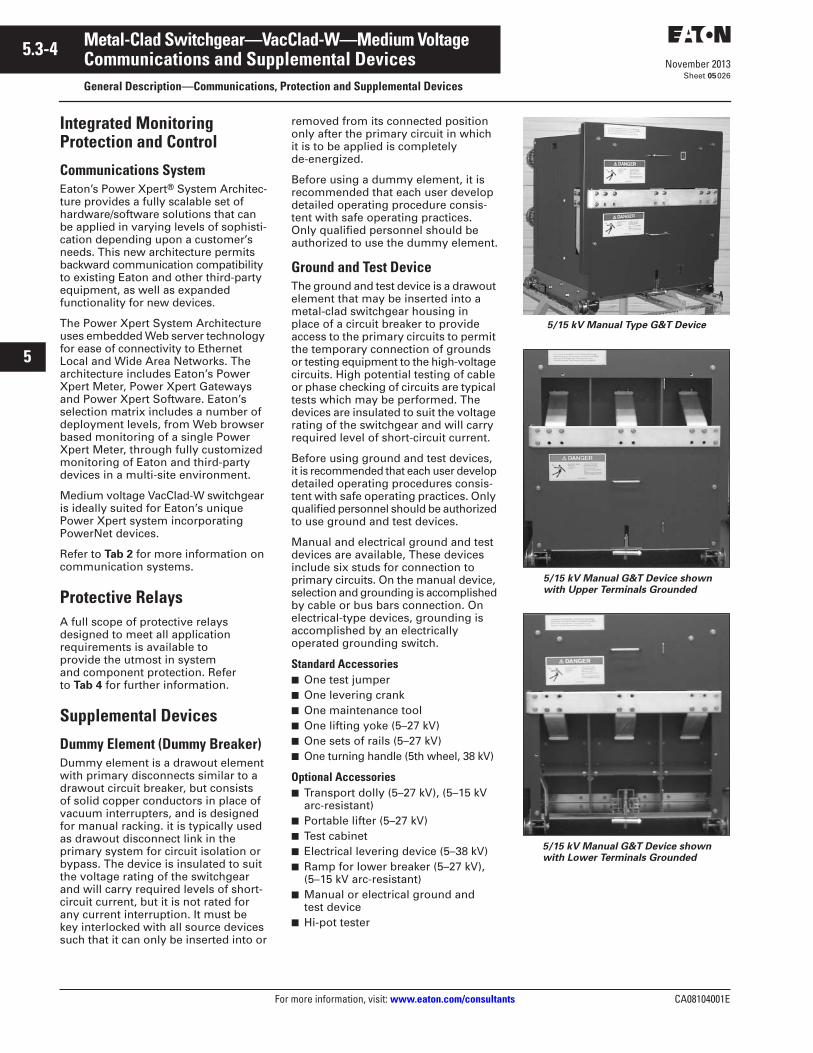
Ground and Test DeviceThe ground and test device is a drawout element that may be inserted into a metal-clad switchgear housing in place of a circuit breaker to provide access to the primary circuits to permit the temporary connection of grounds or testing equipment to the high-voltage circuits. High potential testing of cable or phase checking of circuits are typical tests which may be performed. The devices are insulated to suit the voltage rating of the switchgear and will carry required level of short-circuit current.
Before using ground and test devices, it is recommended that each user develop detailed operating procedures consis-tent with safe operating practices. Only qualified personnel should be authorized to use ground and test devices.
Manual and electrical ground and test devices are available, These devices include six studs for connection to primary circuits. On the manual device, selection and grounding is accomplished by cable or bus bars connection. On electrical-type devices, grounding is accomplished by an electrically operated grounding switch.
Standard Accessories■ One test jumper■ One levering crank■ One maintenance tool■ One lifting yoke (5–27 kV)■ One sets of rails (5–27 kV)■ One turning handle (5th wheel, 38 kV)
Optional Accessories■ Transport dolly (5–27 kV), (5–15 kV
arc-resistant)■ Portable lifter (5–27 kV)■ Test cabinet■ Electrical levering device (5–38 kV)■ Ramp for lower breaker (5–27 kV),
(5–15 kV arc-resistant)■ Manual or electrical ground and
test device■ Hi-pot tester
5/15 kV Manual Type G&T Device
5/15 kV Manual G&T Device shown with Upper Terminals Grounded
5/15 kV Manual G&T Device shown with Lower Terminals Grounded
CA08104001E For more information, visit: www.eaton.com/consultants
5.3-5November 2013
Metal-Clad Switchgear—VacClad-W—Medium Voltage
i
ii
1
2
3
4
5
6
7
8
9
10
11
12
13
14
15
16
17
18
19
20
21
Sheet 05
Drawout Vacuum BreakersIntegral Motorized Remote Racking Option (VCP-W MR2)
027
Integral Motorized Remote Racking Option (VCP-W MR2)
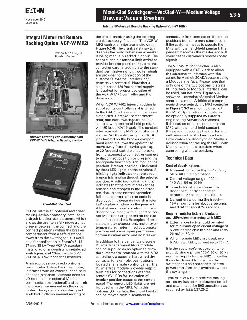
Breaker Levering Pan Assembly with VCP-W MR2 Integral Racking Device
Hand-Held Pendant
VCP-W MR2 is an optional motorized racking device accessory installed in a circuit breaker compartment, which allows the user to safely move a circuit breaker between the connect and dis-connect positions within the breaker compartment from a safe distance away from the switchgear. It is avail-able for application in Eaton’s 5, 15, 27 and 38 kV Type VCP-W standard metal-clad or arc-resistant metal-clad switchgear, and 26-inch-wide 5 kV VCP-W-ND switchgear assemblies.
A microprocessor-based controller card, located below the drive motor, interfaces with an external hand-held pendant (standard), discrete external I/O (optional) or external Modbus communication (optional) and controls the breaker movement via the drive motor. The system is also designed such that it allows manual racking of
the circuit breaker using the levering crank accessory if needed. The VCP-WMR2 controller interface is shown in Figure 5.3-6. The crank safety switch disables the motor whenever a breaker is being manually racked in or out. The connect and disconnect limit switches provide breaker position inputs to the controller card. In addition to the stan-dard permissive switch, two terminals are provided for connection of the customer’s external interlocking/permissive contact(s). Note that a single-phase 120 Vac control supply is required for proper operation of the VCP-W MR2 controller and the drive motor.
When VCP-W MR2 integral racking is supplied, its controller card is wired to the CAT 6 jack installed in the asso-ciated circuit breaker compartment door, and each switchgear lineup is shipped with one hand-held pendant with 30 feet of CAT 6 cable. The pendant interfaces with the MR2 controller card via the CAT 6 cable through a CAT 6 jack located on the breaker compart-ment door. It allows the operator to move away from the switchgear up to 30 feet and rack the circuit breaker from disconnect to connect, or connect to disconnect position by pressing the appropriate function pushbutton on the pendant. Breaker position is indicated by three LED lights on the pendant. A blinking light indicates that the circuit breaker is in motion through the selected position. A solid (non-blinking) light indicates that the circuit breaker has reached and stopped in the selected position. In case normal operation fails, the appropriate error code is displayed in a separate two-character LED display window on the pendant. A list of various error codes and their descriptions along with suggested cor-rective actions are printed on the back side of the pendant. Examples of error states: motor overcurrent, motor over-temperature, motor timed out, breaker position unknown, open permissive, communication error and no breaker.
In addition to the pendant, a discrete I/O interface terminal block module can be supplied as an option to allow the customer to interface with the MR2 controller via external hardwired dry contacts, for example, pushbuttons located at a remote control panel. The I/O interface module provides output terminals for connections of three remote 6V LEDs for indication of breaker position status at the remote panel. The remote LED lights are not included with the MR2. With this optional I/O interface, the circuit breaker can be moved from disconnect to
connect, or from connect to disconnect positions from a remote control panel. If the customer needs to operate the MR2 with the hand-held pendant, the pendant becomes the master and will override the customer’s remote control signals.
The VCP-W MR2 controller is also equipped with a CAT 6 jack to allow the customer to interface with the controller via their SCADA system using a Modbus interface. Please note that only one of the two options, discrete I/O interface or Modbus interface, can be used, but not both. Figure 5.3-7 shows an illustration of a typical Modbus control example. Additional compo-nents shown outside the MR2 controller in Figure 5.3-7 are not included with the MR2. System-level controls can be optionally supplied by Eaton’s Engineering Services & Systems. If the customer needs to operate the MR2 with the hand-held pendant, the pendant becomes the master and will override the Modbus interface. Error codes are displayed on Modbus devices when controlling the MR2 with Modbus and on the pendant when controlling with the pendant.
Technical Data
Control Supply Ratings■ Nominal control voltage—120 Vac,
50 or 60 Hz, single-phase■ Control voltage range—100 to
140 Vac, 50 or 60 Hz■ Time to travel from connect to
disconnect, or disconnect to connect—27 seconds maximum
■ Current draw during the travel—15A maximum for about 3 seconds and 3.6A for about 24 seconds
Requirements for External Contacts and LEDs when Interfacing with MR2■ External contacts should be rated
for minimum open circuit voltage of 5 Vdc, and be able to close and carry 20 mA at 5 Vdc
■ When remote LEDs are used, use 5 Vdc rated LEDs, current up to 20 mA
It is the customer’s responsibility to provide single-phase 120V, 50 or 60 Hz nominal supply for the MR2 controller. It can be derived from within the switchgear if an appropriate control power transformer is available within the switchgear.
Type VCP-W MR2 motorized racking accessory has been endurance tested and guaranteed for 500 operations as required by IEEE C37.20.2.
VCP-W MR2 Integral Racking Device
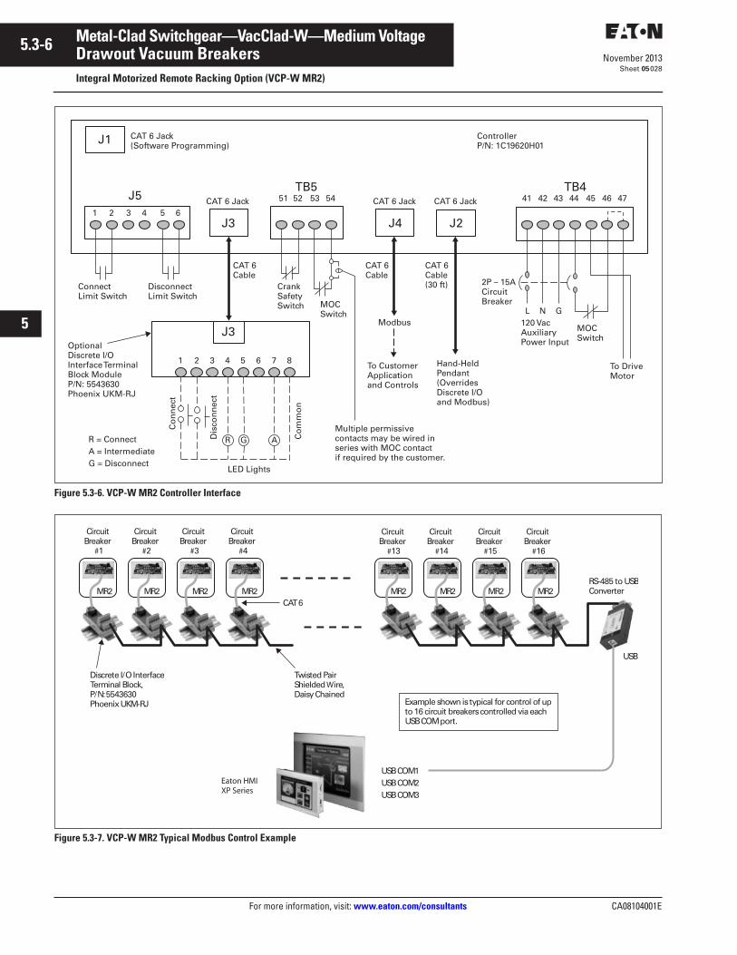
5.3-6
For more information, visit: www.eaton.com/consultants CA08104001E
November 2013
Metal-Clad Switchgear—VacClad-W—Medium Voltage
i
ii
1
2
3
4
5
6
7
8
9
10
11
12
13
14
15
16
17
18
19
20
21
Sheet 05
Drawout Vacuum BreakersIntegral Motorized Remote Racking Option (VCP-W MR2)
028
Figure 5.3-6. VCP-W MR2 Controller Interface
Figure 5.3-7. VCP-W MR2 Typical Modbus Control Example
J1 CAT 6 Jack(Software Programming)
J51 2 3 4 5 6
ConnectLimit Switch
DisconnectLimit Switch
J3
CAT 6 Jack
CAT 6Cable
51 52 53 54TB5
J4
CAT 6 Jack
J2
CAT 6 Jack
CrankSafetySwitch
CAT 6Cable
Modbus
41 42 43 44 45 46 47TB4
ControllerP/N: 1C19620H01
MOCSwitch
To DriveMotor
MOCSwitch
120 VacAuxiliary Power Input
L N G
2P – 15ACircuit Breaker
CAT 6Cable(30 ft)
To CustomerApplicationand Controls
Hand-HeldPendant(OverridesDiscrete I/Oand Modbus)
J3
Multiple permissivecontacts may be wired in series with MOC contactif required by the customer.
Optional Discrete I/O Interface Terminal Block Module P/N: 5543630Phoenix UKM-RJ
1 2 3 4 5 6 7 8
LED Lights
R G A
Co
nn
ect
Dis
con
nec
t
Co
mm
on
R = ConnectA = IntermediateG = Disconnect
Discrete I/O InterfaceTerminal Block, P/N: 5543630Phoenix UKM-RJ
MR2
CircuitBreaker
#1
MR2 MR2 MR2
CircuitBreaker
#2
CircuitBreaker
#3
CircuitBreaker
#4
Twisted PairShielded Wire,Daisy Chained
CAT 6MR2
CircuitBreaker
#13
MR2 MR2 MR2
CircuitBreaker
#14
CircuitBreaker
#15
CircuitBreaker
#16
RS-485 to USBConverter
USB
USB COM1USB COM2USB COM3
Eaton HMIXP Series
Example shown is typical for control of up to 16 circuit breakers controlled via each USB COM port.
CA08104001E For more information, visit: www.eaton.com/consultants
5.4-1November 2013
Metal-Clad Switchgear—VacClad-W—Medium Voltage
i
ii
1
2
3
4
5
6
7
8
9
10
11
12
13
14
15
16
17
18
19
20
21
Sheet 05
Drawout Vacuum BreakersTechnical Data—Standard VCP-W Circuit Breakers
029
Discussion of changes in the Rated Voltage Range Factor, K, or “K-factor” in Circuit Breaker Rating Structure In 1997 and 2000 editions of ANSI C37.06, under Table 1, preferred values for the rated voltage range factor, K, were set to 1.0 for all indoor circuit breaker ratings. This was done because interrupting capabilities of today’s vacuum circuit breakers are better represented by K = 1.0. Unlike old air-magnetic and oil circuit breakers, today’s vacuum breakers generally do not require a reduction in interrupting current, as the operating voltage is raised to rated maximum voltage, for example from 11.5 kV up to 15 kV. The interrupting capability of vacuum circuit breakers is essentially constant over the entire range of operating voltages, up to and including its rated maximum voltage. The change was also made as a step toward harmonizing preferred ANSI ratings with the preferred ratings of IEC standards. It was further recognized that it is much simpler to select and apply circuit breakers rated on the basis of K = 1.0.
The change in the K value, however, in no way affects the ratings and capabilities of circuit breakers originally tested and rated on the basis of K > 1 in the earlier editions of C37.06. Existing circuit breakers, with ratings based on K > 1.0, are still perfectly valid, meet the latest editions of the standards, and should be continued to be applied as they have been in the past. The original K > 1.0 ratings are neither “obsolete” nor “inferior” to the new K = 1.0 ratings; they are just different. The new 1997 and 2000 editions of ANSI standard C37.06 still include the earlier K > 1 ratings as Table A1 and A1A. The change from K > 1.0 to K = 1.0 should be implemented by manufacturers as they develop and test new circuit breakers designs. The change does not require, recommend or suggest that manufactures re-rate and re-test existing breakers to new standard. And accordingly, Eaton continues to offer both circuit breakers rated on the traditional basis of K > 1.0 just as thousands of those breakers have been applied for variety of circuit switching applications worldwide, and also as Eaton develops new breakers, they are rated and tested to the new
K = 1 ratings. As a leader in vacuum interruption technology, Eaton continues to provide a wide choice of modern vacuum circuit breakers so that the user can select the most economical circuit breaker that can satisfy their circuit switching application.
■ Table 5.4-1A includes 5/15 kV circuit breakers rated on the basis of K = 1.0 in accordance with revised ANSI standards
■ Table 5.4-1B includes capabilities of traditional 5/15 kV circuit breakers rated on the basis of K > 1.0
■ Table 5.4-1C includes 27/38 kV circuit breakers rated on the basis of K = 1.0
■ Table 5.4-2 includes circuit breaker designs, rated on the basis of K = 1.0 with “extra capabilities” for those applications whose requirements go beyond what is usually experienced in normal distribution circuit applications
■ Table 5.4-3 includes circuit breakers for special generator applications
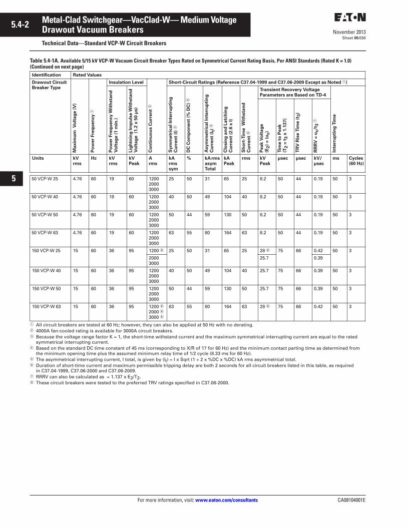
5.4-2
For more information, visit: www.eaton.com/consultants CA08104001E
November 2013
Metal-Clad Switchgear—VacClad-W— Medium Voltage
i
ii
1
2
3
4
5
6
7
8
9
10
11
12
13
14
15
16
17
18
19
20
21
Sheet 05
Drawout Vacuum BreakersTechnical Data—Standard VCP-W Circuit Breakers
030
Table 5.4-1A. Available 5/15 kV VCP-W Vacuum Circuit Breaker Types Rated on Symmetrical Current Rating Basis, Per ANSI Standards (Rated K = 1.0) (Continued on next page)
� All circuit breakers are tested at 60 Hz; however, they can also be applied at 50 Hz with no derating.� 4000A fan-cooled rating is available for 3000A circuit breakers.� Because the voltage range factor K = 1, the short-time withstand current and the maximum symmetrical interrupting current are equal to the rated
symmetrical interrupting current.� Based on the standard DC time constant of 45 ms (corresponding to X/R of 17 for 60 Hz) and the minimum contact parting time as determined from
the minimum opening time plus the assumed minimum relay time of 1/2 cycle (8.33 ms for 60 Hz).� The asymmetrical interrupting current, I total, is given by (It) = I x Sqrt (1 + 2 x %DC x %DC) kA rms asymmetrical total.� Duration of short-time current and maximum permissible tripping delay are both 2 seconds for all circuit breakers listed in this table, as required
in C37.04-1999, C37.06-2000 and C37.06-2009.� RRRV can also be calculated as = 1.137 x E2/T2.� These circuit breakers were tested to the preferred TRV ratings specified in C37.06-2000.
Identification Rated Values
Drawout Circuit Breaker Type
Maxim
um
V
olt
ag
e (
V)
Po
wer
Fre
qu
en
cy �
Insulation Level
Co
nti
nu
ou
s C
urr
en
t �
Short-Circuit Ratings (Reference C37.04-1999 and C37.06-2009 Except as Noted �)
Po
wer
Fre
qu
en
cy W
ith
sta
nd
V
olt
ag
e (
1 m
in.)
Lig
htn
ing
Im
pu
lse W
ith
sta
nd
V
olt
ag
e (1
.2 x
50 µ
s)
Sym
metr
ical In
terr
up
tin
g
Cu
rren
t (I
) �
DC
Co
mp
on
en
t (%
DC
) �
Asym
metr
ical In
terr
up
tin
g
Cu
rren
t (I
t) �
Clo
sin
g a
nd
Latc
hin
g
Cu
rren
t (2
.6 x
I)
Sh
ort
-Tim
e W
ith
sta
nd
C
urr
en
t �
Transient Recovery Voltage Parameters are Based on TD-4
Inte
rru
pti
ng
Tim
e
Peak V
olt
ag
e
(E2)
= (
uc)
Tim
e t
o P
eak
(T2 =
t3 x
1.1
37)
TR
V R
ise T
ime (
t 3)
RR
RV
= u
c/t
3 �
Units kV rms
Hz kV rms
kV Peak
A rms
kA rms sym
% kA rms asym Total
kA Peak
rms kV Peak
µsec µsec kV/µsec
ms Cycles (60 Hz)
50 VCP-W 25 4.76 60 19 60 120020003000
25 50 31 65 25 8.2 50 44 0.19 50 3
50 VCP-W 40 4.76 60 19 60 120020003000
40 50 49 104 40 8.2 50 44 0.19 50 3
50 VCP-W 50 4.76 60 19 60 120020003000
50 44 59 130 50 8.2 50 44 0.19 50 3
50 VCP-W 63 4.76 60 19 60 120020003000
63 55 80 164 63 8.2 50 44 0.19 50 3
150 VCP-W 25 15 60 36 95 1200 � 25 50 31 65 25 28 � 75 66 0.42 50 3
20003000
25.7 0.39
150 VCP-W 40 15 60 36 95 120020003000
40 50 49 104 40 25.7 75 66 0.39 50 3
150 VCP-W 50 15 60 36 95 120020003000
50 44 59 130 50 25.7 75 66 0.39 50 3
150 VCP-W 63 15 60 36 95 1200 �2000 �3000 �
63 55 80 164 63 28 � 75 66 0.42 50 3
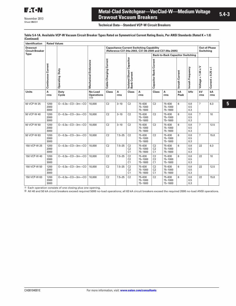
CA08104001E For more information, visit: www.eaton.com/consultants
5.4-3November 2013
Metal-Clad Switchgear—VacClad-W—Medium Voltage
i
ii
1
2
3
4
5
6
7
8
9
10
11
12
13
14
15
16
17
18
19
20
21
Sheet 05
Drawout Vacuum BreakersTechnical Data—Standard VCP-W Circuit Breakers
031
Table 5.4-1A. Available VCP-W Vacuum Circuit Breaker Types Rated on Symmetrical Current Rating Basis, Per ANSI Standards (Rated K = 1.0) (Continued)
Each operation consists of one closing plus one opening.� All 40 and 50 kA circuit breakers exceed required 5000 no-load operations; all 63 kA circuit breakers exceed the required 2000 no-load ANSI operations.
Identification Rated Values
Drawout Circuit Breaker Type
Co
nti
nu
ou
s C
urr
en
t
Op
era
tin
g D
uty
Mech
an
ical E
nd
ura
nce
Capacitance Current Switching Capability (Reference C37.04a-2003, C37.06-2009 and C37.09a-2005)
Out-of-Phase Switching
Cab
le-C
harg
ing
Cu
rren
t
Iso
late
d S
hu
nt
Cap
acit
or
Ban
k C
urr
en
t
Back-to-Back Capacitor Switching
Cap
acit
or
Ban
k C
urr
en
t
Inru
sh
Cu
rren
t
Inru
sh
Fre
qu
en
cy
Vo
ltag
e =
1.4
4 x
V
Cu
rren
t =
0.2
5 x
I
Units A rms
Duty Cycle
No-Load Operations�
Class A rms
Class A rms
Class A rms
kA Peak
kHz kV rms
kA rms
50 VCP-W 25 120020003000
O—0.3s—CO—3m—CO 10,000 C2 3–10 C2 75–63075–100075–1600
C2 75–63075–100075–1600
6 0.80.50.3
7 6.3
50 VCP-W 40 120020003000
O—0.3s—CO—3m—CO 10,000 C2 3–10 C2 75–63075–100075–1600
C2 75–63075–100075–1600
6 0.80.50.3
7 10
50 VCP-W 50 120020003000
O—0.3s—CO—3m—CO 10,000 C2 3–10 C2 75–63075–100075–1600
C2 75–63075–100075–1600
6 0.80.50.3
7 12.5
50 VCP-W 63 120020003000
O—0.3s—CO—3m—CO 10,000 C2 7.5–25 C2 75–63075–100075–1600
C2 75–63075–100075–1600
6 0.80.50.3
7 15.8
150 VCP-W 25 120020003000
O—0.3s—CO—3m—CO 10,000 C2 7.5–25 C2C2C1
75–63075–100075–1600
C2C2C1
75–63075–100075–1600
6 0.80.50.3
22 6.3
150 VCP-W 40 120020003000
O—0.3s—CO—3m—CO 10,000 C2 7.5–25 C2C2C1
75–63075–100075–1600
C2C2C1
75–63075–100075–1600
6 0.80.50.3
22 10
150 VCP-W 50 120020003000
O—0.3s—CO—3m—CO 10,000 C2 7.5–25 C2C2C1
75–63075–100075–1600
C2C2C1
75–63075–100075–1600
6 0.80.50.3
22 12.5
150 VCP-W 63 120020003000
O—0.3s—CO—3m—CO 10,000 C2 7.5–25 C2 75–63075–100075–1600
C2 75–63075–100075–1600
6 0.80.50.3
22 15.8
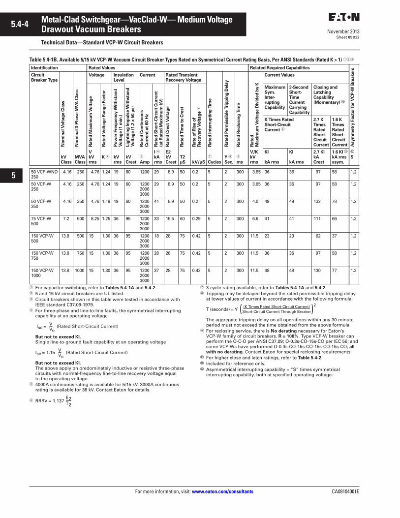
5.4-4
For more information, visit: www.eaton.com/consultants CA08104001E
November 2013
Metal-Clad Switchgear—VacClad-W— Medium Voltage
i
ii
1
2
3
4
5
6
7
8
9
10
11
12
13
14
15
16
17
18
19
20
21
Sheet 05
Drawout Vacuum BreakersTechnical Data—Standard VCP-W Circuit Breakers
032
Table 5.4-1B. Available 5/15 kV VCP-W Vacuum Circuit Breaker Types Rated on Symmetrical Current Rating Basis, Per ANSI Standards (Rated K > 1) ���
� For capacitor switching, refer to Tables 5.4-1A and 5.4-2.� 5 and 15 kV circuit breakers are UL listed.� Circuit breakers shown in this table were tested in accordance with
IEEE standard C37.09-1979.� For three-phase and line-to-line faults, the symmetrical interrupting
capability at an operating voltage
Isc = (Rated Short-Circuit Current)
But not to exceed KI.Single line-to-ground fault capability at an operating voltage
Isc = 1.15 (Rated Short-Circuit Current)
But not to exceed KI.The above apply on predominately inductive or resistive three-phase circuits with normal-frequency line-to-line recovery voltage equal to the operating voltage.
� 4000A continuous rating is available for 5/15 kV. 3000A continuous rating is available for 38 kV. Contact Eaton for details.
� RRRV = 1.137
� 3-cycle rating available, refer to Tables 5.4-1A and 5.4-2.� Tripping may be delayed beyond the rated permissible tripping delay
at lower values of current in accordance with the following formula:
T (seconds) = Y
The aggregate tripping delay on all operations within any 30-minute period must not exceed the time obtained from the above formula.
For reclosing service, there is No derating necessary for Eaton’s VCP-W family of circuit breakers. R = 100%. Type VCP-W breaker can perform the O-C-O per ANSI C37.09; O-0.3s-CO-15s-CO per IEC 56; and some VCP-Ws have performed O-0.3s-CO-15s-CO-15s-CO-15s-CO; all with no derating. Contact Eaton for special reclosing requirements.
� For higher close and latch ratings, refer to Table 5.4-2.� Included for reference only.� Asymmetrical interrupting capability = “S” times symmetrical
interrupting capability, both at specified operating voltage.
Identification Rated Values Related Required Capabilities
Asym
metr
y F
acto
r fo
r V
CP
-W B
reakers
Circuit Breaker Type
No
min
al V
olt
ag
e C
lass
No
min
al 3-P
hase M
VA
Cla
ss
Voltage Insulation Level
Current Rated TransientRecovery Voltage
Rate
d In
terr
up
tin
g T
ime
Rate
d P
erm
issib
le T
rip
pin
g D
ela
y
Rate
d R
eclo
sin
g T
ime
Rate
dM
axim
um
Vo
ltag
e D
ivid
ed
by K
Current Values
Rate
d M
axim
um
Vo
ltag
e
Rate
d V
olt
ag
e R
an
ge F
acto
r
Po
wer
Fre
qu
en
cy W
ith
sta
nd
Vo
ltag
e (
1 m
in.)
Lig
htn
ing
Im
pu
lse W
ith
sta
nd
Vo
ltag
e (
1.2
x 5
0 µ
s)
Rate
d C
on
tin
uo
us
Cu
rren
t at
60 H
z
Rate
d S
ho
rt-C
ircu
it C
urr
en
t(a
t R
ate
d M
axim
um
kV
)
Rate
d C
rest
Vo
ltag
e
Rate
d T
ime t
o C
rest
Rate
of
Ris
e o
f R
eco
very
Vo
ltag
e �
MaximumSym.Inter-ruptingCapability
3-Second Short-Time Current Carrying Capability
Closing and LatchingCapability (Momentary) �
K Times Rated Short-Circuit Current �
2.7 KTimesRated Short-Circuit Current
1.6 KTimesRated Short-Circuit Current
kVClass
MVAClass
VkV rms
K � kV rms
kV Crest
�
Amp
I �
kA rms
E2kV Crest
T2µS kV/µS
�
CyclesY �
Sec.
ms
V/KkV rms
KI
kA rms
KI
kA rms
2.7 KIkACrest
1.6 KI �
kA rms asym.
�
S
50 VCP-WND250
4.16 250 4.76 1.24 19 60 1200 29 8.9 50 0.2 5 2 300 3.85 36 36 97 58 1.2
50 VCP-W250
4.16 250 4.76 1.24 19 60 120020003000
29 8.9 50 0.2 5 2 300 3.85 36 36 97 58 1.2
50 VCP-W350
4.16 350 4.76 1.19 19 60 120020003000
41 8.9 50 0.2 5 2 300 4.0 49 49 132 78 1.2
75 VCP-W500
7.2 500 8.25 1.25 36 95 120020003000
33 15.5 60 0.29 5 2 300 6.6 41 41 111 66 1.2
150 VCP-W500
13.8 500 15 1.30 36 95 120020003000
18 28 75 0.42 5 2 300 11.5 23 23 62 37 1.2
150 VCP-W750
13.8 750 15 1.30 36 95 120020003000
28 28 75 0.42 5 2 300 11.5 36 36 97 58 1.2
150 VCP-W1000
13.8 1000 15 1.30 36 95 120020003000
37 28 75 0.42 5 2 300 11.5 48 48 130 77 1.2
VVo
VVo
E2T2-------
(K Times Rated Short-Circuit Current)Short-Circuit Current Through Breaker( )
2
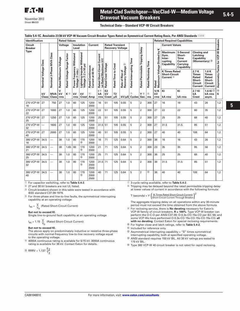
CA08104001E For more information, visit: www.eaton.com/consultants
5.4-5November 2013
Metal-Clad Switchgear—VacClad-W—Medium Voltage
i
ii
1
2
3
4
5
6
7
8
9
10
11
12
13
14
15
16
17
18
19
20
21
Sheet 05
Drawout Vacuum BreakersTechnical Data—Standard VCP-W Circuit Breakers
033
Table 5.4-1C. Available 27/38 kV VCP-W Vacuum Circuit Breaker Types Rated on Symmetrical Current Rating Basis, Per ANSI Standards ���
� For capacitor switching, refer to Table 5.4-2.� 27 and 38 kV breakers are not UL listed.� Circuit breakers shown in this table were tested in accordance with
IEEE standard C37.09-1979.� For three-phase and line-to-line faults, the symmetrical interrupting
capability at an operating voltage
Isc = (Rated Short-Circuit Current)
But not to exceed KI.Single line-to-ground fault capability at an operating voltage
Isc = 1.15 (Rated Short-Circuit Current)
But not to exceed KI.The above apply on predominately inductive or resistive three-phase circuits with normal-frequency line-to-line recovery voltage equal to the operating voltage.
� 4000A continuous rating is available for 5/15 kV. 3000A continuous rating is available for 38 kV. Contact Eaton for details.
� RRRV = 1.137
� 3-cycle rating available, refer to Table 5.4-2.� Tripping may be delayed beyond the rated permissible tripping delay
at lower values of current in accordance with the following formula:
T (seconds) = Y
The aggregate tripping delay on all operations within any 30-minute period must not exceed the time obtained from the above formula.
For reclosing service, there is No derating necessary for Eaton’s VCP-W family of circuit breakers. R = 100%. Type VCP-W breaker can perform the O-C-O per ANSI C37.09; O-0.3s-CO-15s-CO per IEC 56; and some VCP-Ws have performed O-0.3s-CO-15s-CO-15s-CO-15s-CO; all with no derating. Contact Eaton for special reclosing requirements.
� For higher close and latch ratings, refer to Table 5.4-2.� Included for reference only.� Asymmetrical interrupting capability = “S” times symmetrical
interrupting capability, both at specified operating voltage.� ANSI standard requires 150 kV BIL. All 38 kV ratings are tested to
170 kV BIL.� Type 380 VCP-W 40 circuit breaker is not rated for rapid reclosing.
Identification Rated Values Related Required Capabilities
Asym
metr
y F
acto
r fo
r V
CP
-W B
reakers
Circuit Breaker Type
No
min
al V
olt
ag
e C
lass
No
min
al 3-P
hase M
VA
Cla
ss
Voltage Insulation Level
Current Rated TransientRecovery Voltage
Rate
d In
terr
up
tin
g T
ime
Rate
d P
erm
issib
le T
rip
pin
g D
ela
y
Rate
d R
eclo
sin
g T
ime
Rate
d
Maxim
um
Vo
ltag
e D
ivid
ed
by K
Current Values
Rate
d M
axim
um
Vo
ltag
e
Rate
d V
olt
ag
e R
an
ge F
acto
r
Po
wer
Fre
qu
en
cy W
ith
sta
nd
Vo
ltag
e (
1 m
in.)
Lig
htn
ing
Im
pu
lse W
ith
sta
nd
Vo
ltag
e (
1.2
x 5
0 µ
s)
Rate
d C
on
tin
uo
us
Cu
rren
t at
60 H
z
Rate
d S
ho
rt-C
ircu
it C
urr
en
t(a
t R
ate
d M
axim
um
kV
)
Rate
d C
rest
Vo
ltag
e
Rate
d T
ime t
o C
rest
Rate
of
Ris
e o
f R
eco
very
Vo
ltag
e �
MaximumSym.Inter-ruptingCapability
3-Second Short-Time Current Carrying Capability
Closing and LatchingCapability (Momentary) �
K Times Rated Short-Circuit Current �
2.7 K TimesRated Short-Circuit Current
1.6 K TimesRated Short-Circuit Current
kVClass
MVAClass
VkV rms
K � kV rms
kV Crest
�
Amp
I �
kA rms
E2kV Crest
T2µS kV/µS
�
CyclesY �
Sec.
ms
V/KkV rms
KI
kA rms
KI
kA rms
2.7 KIkA Crest
1.6 KI �
kA rms asym.
�
S
270 VCP-W16
27 750 27 1.0 60 125 12002000
16 51 105 0.55 5 2 300 27 16 16 43 26 1.2
270 VCP-W22
27 1000 27 1.0 60 125 12002000
22 51 105 0.55 5 2 300 27 22 22 60 35 1.2
270 VCP-W25
27 1250 27 1.0 60 125 12002000
25 51 105 0.55 5 2 300 27 25 25 68 40 1.2
270 VCP-W 32
— 1600 27 1.0 60 125 12002000
31.5 51 105 0.55 5 2 300 27 31.5 31.5 85 51 1.2
270 VCP-W 40
27 2000 27 1.0 60 125 12002000
40 51 105 0.55 5 2 300 27 40 40 108 64 1.2
380 VCP-W16
34.5 — 38 1.0 80 170�
12002000
16 71 125 0.64 5 2 300 38 16 16 43 26 1.2
380 VCP-W21
34.5 — 38 1.65 80 170�
12002000
21 71 125 0.64 5 2 300 23 35 35 95 56 1.2
380 VCP-W25
34.5 — 38 1.0 80 170�
12002000
25 71 125 0.64 5 2 300 38 25 25 68 40 1.2
380 VCP-W32
34.5 — 38 1.0 80 170�
120020002500
31.5 71 125 0.64 5 2 300 38 31.5 31.5 85 51 1.2
380 VCP-W40
34.5 — 38 1.0 80 170�
120020002500
40 71 125 0.64 5 2 � 38 40 40 108 64 1.2
VVo
VVo
E2T2-------
(K Times Rated Short-Circuit Current)Short-Circuit Current Through Breaker( )
2
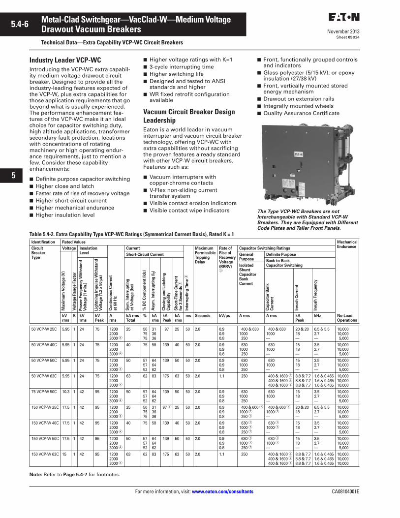
5.4-6
For more information, visit: www.eaton.com/consultants CA08104001E
November 2013
Metal-Clad Switchgear—VacClad-W—Medium Voltage
i
ii
1
2
3
4
5
6
7
8
9
10
11
12
13
14
15
16
17
18
19
20
21
Sheet 05
Drawout Vacuum BreakersTechnical Data—Extra Capability VCP-WC Circuit Breakers
034
Industry Leader VCP-WCIntroducing the VCP-WC extra capabil-ity medium voltage drawout circuit breaker. Designed to provide all the industry-leading features expected of the VCP-W, plus extra capabilities for those application requirements that go beyond what is usually experienced. The performance enhancement fea-tures of the VCP-WC make it an ideal choice for capacitor switching duty, high altitude applications, transformer secondary fault protection, locations with concentrations of rotating machinery or high operating endur-ance requirements, just to mention a few. Consider these capability enhancements:
■ Definite purpose capacitor switching■ Higher close and latch■ Faster rate of rise of recovery voltage■ Higher short-circuit current■ Higher mechanical endurance■ Higher insulation level
■ Higher voltage ratings with K=1■ 3-cycle interrupting time■ Higher switching life■ Designed and tested to ANSI
standards and higher■ WR fixed retrofit configuration
available
Vacuum Circuit Breaker Design LeadershipEaton is a world leader in vacuum interrupter and vacuum circuit breaker technology, offering VCP-WC with extra capabilities without sacrificing the proven features already standard with other VCP-W circuit breakers. Features such as:
■ Vacuum interrupters with copper-chrome contacts
■ V-Flex non-sliding current transfer system
■ Visible contact erosion indicators■ Visible contact wipe indicators
■ Front, functionally grouped controls and indicators
■ Glass-polyester (5/15 kV), or epoxy insulation (27/38 kV)
■ Front, vertically mounted stored energy mechanism
■ Drawout on extension rails■ Integrally mounted wheels■ Quality Assurance Certificate
The Type VCP-WC Breakers are not Interchangeable with Standard VCP-W Breakers. They are Equipped with Different Code Plates and Taller Front Panels.
Table 5.4-2. Extra Capability Type VCP-WC Ratings (Symmetrical Current Basis), Rated K = 1
Note: Refer to Page 5.4-7 for footnotes.
Identification Rated Values MechanicalEnduranceCircuit
BreakerType
Voltage InsulationLevel
Co
nti
nu
ou
s C
urr
en
t at
60 H
z
Current
Inte
rru
pti
ng
Tim
e �
MaximumPermissibleTrippingDelay
Rate ofRise ofRecoveryVoltage(RRRV)�
Capacitor Switching Ratings
Maxim
um
Vo
ltag
e (
V)
Vo
ltag
e R
an
ge F
act
or
Short-Circuit Current GeneralPurpose
Definite Purpose
Po
wer
Fre
qu
en
cy W
ith
stan
dV
olt
ag
e (
1 m
in.)
Lig
htn
ing
Im
pu
lse W
ith
stan
dV
olt
ag
e (
1.2
x 5
0 µ
s)
Sym
. In
terr
up
tin
g
at
Vo
ltag
e (
Isc)
% D
C C
om
po
nen
t (I
dc)
Asy
m. In
terr
up
tin
g (
I t)
Clo
sin
g a
nd
Latc
hin
gC
ap
ab
ilit
y
Sh
ort
-Tim
e C
urr
en
tfo
r 3 S
eco
nd
s �
Back-to-BackCapacitor SwitchingIsolated
ShuntCapacitor BankCurrent
Cap
aci
tor
Ban
kC
urr
en
t
Inru
sh C
urr
en
t
Inru
sh F
req
uen
cykVrms
K kVrms
kVPeak
Arms
kA rmsTotal
% kArms
kAPeak
kArms
ms Seconds kV/µs A rms A rms kAPeak
kHz No-LoadOperations
50 VCP-W 25C 5.95 1 24 75 120020003000 �
25 507575
313636
97 25 50 2.0 0.90.90.8
400 & 6301000 250
400 & 6301000 —
20 & 2018—
6.5 & 5.52.7—
10,00010,000 5,000
50 VCP-W 40C 5.95 1 24 75 120020003000 �
40 75 58 139 40 50 2.0 0.90.90.8
630 1000 250
630 1000 —
1518—
3.52.7—
10,00010,000 5,000
50 VCP-W 50C 5.95 1 24 75 120020003000 �
50 575752
646462
139 50 50 2.0 0.90.90.8
630 1000 250
630 1000 —
1518—
3.52.7—
10,00010,000 5,000
50 VCP-W 63C 5.95 1 24 75 120020003000 �
63 62 83 175 63 50 2.0 1.1 250 400 & 1600 � 400 & 1600 � 400 & 1600 �
8.8 & 7.78.8 & 7.78.8 & 7.7
1.6 & 0.4651.6 & 0.4651.6 & 0.465
10,00010,00010,000
75 VCP-W 50C 10.3 1 42 95 120020003000 �
50 575752
646462
139 50 50 2.0 0.90.90.8
630 1000 250
630 1000 —
1518—
3.52.7—
10,00010,000 5,000
150 VCP-W 25C 17.5 1 42 95 120020003000 �
25 507575
313636
97 � 25 50 2.0 0.90.90.8
400 & 600 �1000 � 250 �
400 & 600 �1000 �—
20 & 2018—
6.5 & 5.52.7—
10,00010,000 5,000
150 VCP-W 40C 17.5 1 42 95 120020003000 �
40 75 58 139 40 50 2.0 0.90.90.8
630 �1000 � 250 �
630 �1000 �—
1518—
3.52.7—
10,00010,000 5,000
150 VCP-W 50C 17.5 1 42 95 120020003000 �
50 575752
646462
139 50 50 2.0 0.90.90.8
630 �1000 � 250 �
630 �1000 �—
1518—
3.52.7—
10,00010,000 5,000
150 VCP-W 63C 15 1 42 95 120020003000 �
63 62 83 175 63 50 2.0 1.1 250 400 & 1600 � 400 & 1600 � 400 & 1600 �
8.8 & 7.78.8 & 7.78.8 & 7.7
1.6 & 0.4651.6 & 0.4651.6 & 0.465
10,00010,00010,000
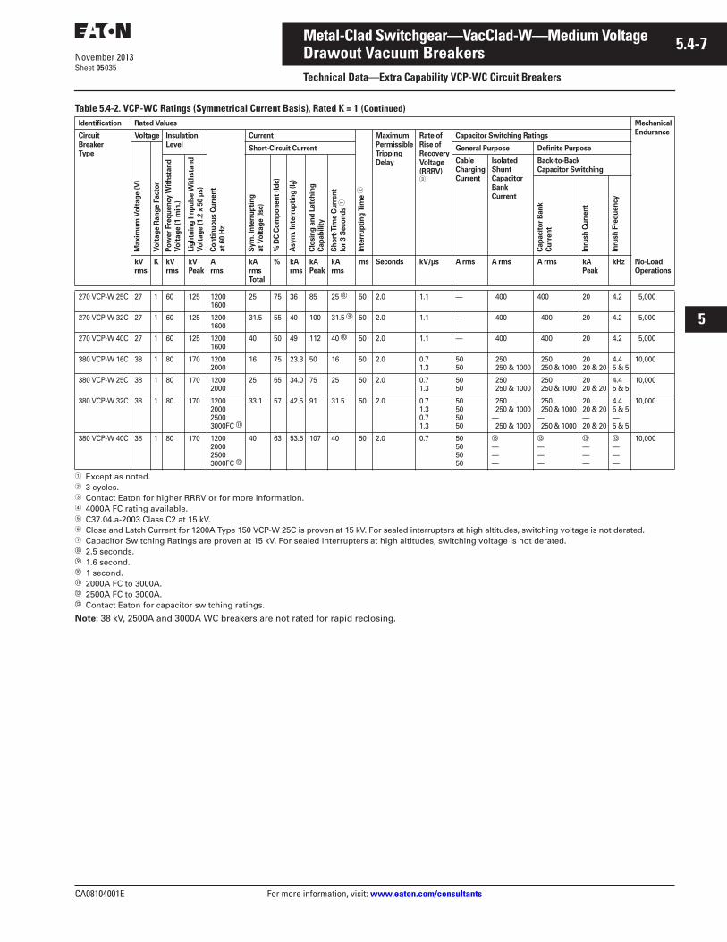
CA08104001E For more information, visit: www.eaton.com/consultants
5.4-7November 2013
Metal-Clad Switchgear—VacClad-W—Medium Voltage
i
ii
1
2
3
4
5
6
7
8
9
10
11
12
13
14
15
16
17
18
19
20
21
Sheet 05
Drawout Vacuum BreakersTechnical Data—Extra Capability VCP-WC Circuit Breakers
035
Table 5.4-2. VCP-WC Ratings (Symmetrical Current Basis), Rated K = 1 (Continued)
� Except as noted.� 3 cycles.� Contact Eaton for higher RRRV or for more information.� 4000A FC rating available.� C37.04.a-2003 Class C2 at 15 kV.� Close and Latch Current for 1200A Type 150 VCP-W 25C is proven at 15 kV. For sealed interrupters at high altitudes, switching voltage is not derated.� Capacitor Switching Ratings are proven at 15 kV. For sealed interrupters at high altitudes, switching voltage is not derated.� 2.5 seconds.� 1.6 second.� 1 second.� 2000A FC to 3000A.� 2500A FC to 3000A.� Contact Eaton for capacitor switching ratings.
Note: 38 kV, 2500A and 3000A WC breakers are not rated for rapid reclosing.
Identification Rated Values Mechanical
EnduranceCircuit
Breaker
Type
Voltage Insulation
Level
Co
nti
nu
ou
s C
urr
en
t
at
60 H
z
Current
Inte
rru
pti
ng
Tim
e �
Maximum
Permissible
Tripping
Delay
Rate of
Rise of
Recovery
Voltage
(RRRV)�
Capacitor Switching RatingsM
axim
um
Vo
ltag
e (
V)
Vo
ltag
e R
an
ge F
act
or
Short-Circuit Current General Purpose Definite Purpose
Po
wer
Fre
qu
en
cy W
ith
stan
d
Vo
ltag
e (
1 m
in.)
Lig
htn
ing
Im
pu
lse W
ith
stan
d
Vo
ltag
e (
1.2
x 5
0 µ
s)
Sym
. In
terr
up
tin
g
at
Vo
ltag
e (
Isc)
% D
C C
om
po
nen
t (I
dc)
Asy
m. In
terr
up
tin
g (
I t)
Clo
sin
g a
nd
Latc
hin
g
Cap
ab
ilit
y
Sh
ort
-Tim
e C
urr
en
t
for
3 S
eco
nd
s �
Back-to-Back
Capacitor Switching
Cable
Charging
Current
Isolated
Shunt
Capacitor
Bank
Current
Cap
aci
tor
Ban
k
Cu
rren
t
Inru
sh C
urr
en
t
Inru
sh F
req
uen
cy
kV
rms
K kV
rms
kV
Peak
A
rms
kA
rms
Total
% kA
rms
kA
Peak
kA
rms
ms Seconds kV/µs A rms A rms A rms kA
Peak
kHz No-Load
Operations
270 VCP-W 25C 27 1 60 125 12001600
25 75 36 85 25 � 50 2.0 1.1 — 400 400 20 4.2 5,000
270 VCP-W 32C 27 1 60 125 12001600
31.5 55 40 100 31.5 � 50 2.0 1.1 — 400 400 20 4.2 5,000
270 VCP-W 40C 27 1 60 125 12001600
40 50 49 112 40 � 50 2.0 1.1 — 400 400 20 4.2 5,000
380 VCP-W 16C 38 1 80 170 12002000
16 75 23.3 50 16 50 2.0 0.71.3
5050
250 250 & 1000
250 250 & 1000
2020 & 20
4.45 & 5
10,000
380 VCP-W 25C 38 1 80 170 12002000
25 65 34.0 75 25 50 2.0 0.71.3
5050
250 250 & 1000
250 250 & 1000
2020 & 20
4.45 & 5
10,000
380 VCP-W 32C 38 1 80 170 1200200025003000FC �
33.1 57 42.5 91 31.5 50 2.0 0.71.30.71.3
50505050
250 250 & 1000— 250 & 1000
250 250 & 1000— 250 & 1000
2020 & 20—20 & 20
4.45 & 5—5 & 5
10,000
380 VCP-W 40C 38 1 80 170 1200200025003000FC �
40 63 53.5 107 40 50 2.0 0.7 50505050
�
———
�
———
�
———
�
———
10,000
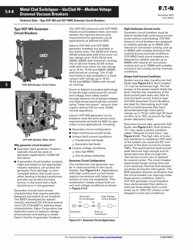
5.4-8
For more information, visit: www.eaton.com/consultants CA08104001E
November 2013
Metal-Clad Switchgear—VacClad-W—Medium Voltage
i
ii
1
2
3
4
5
6
7
8
9
10
11
12
13
14
15
16
17
18
19
20
21
Sheet 05
Drawout Vacuum BreakersTechnical Data—Type VCP-WG and VCP-WRG Generator Circuit Breakers
036
Type VCP-WG Generator Circuit Breakers
VCP-WG Breaker (Front View)
VCP-WG Breaker (Rear View)
Why generator circuit breakers?■ Specially rated generator breakers
typically should be used on generator applications 10,000 kW and above
■ A generator circuit breaker, properly rated and tested to the appropriate industry standard, can protect the generator from damage, or even complete failure, that could occur when feeding a faulted transformer, and also can protect the trans-former, in the event that a fault should occur in the generator
Generator circuits have unique characteristics that require specially designed and tested circuit breakers. The IEEE® developed the special industry standard C37.013 and amend-ment C37.013a-2007 to address these characteristics. Eaton Corporation has dedicated years of research, design, enhancement and testing to create Eaton’s family of generator breakers.
The VCP-WG (drawout) and VCP-WRG (fixed) circuit breakers meet, and even exceed, the rigorous service duty requirements for generator circuit applications as defined by IEEE.
Eaton’s VCP-WG and VCP-WRG generator breakers are available in two frame sizes. The 29.00-inch frame (29.00 inches wide with front cover on) has ratings up to 15 kV, 63 kA and 3000A (4000A with forced-air cooling). The 31.00-inch frame (31.00 inches wide with front cover on) has ratings up to 15 kV, 75 kA and 4000A (5000A with forced-air cooling). The 31.00-inch frame is also available in a fixed version with ratings up to 15 kV, 75 kA and 6000A (7000A with forced-air cooling).
Count on Eaton’s innovative technology to handle high continuous AC current and voltage, then safely switch through extreme out-of-phase voltages and high-stress asymmetrical currents using “clean and green” vacuum inter-ruption without fail for over 10,000 normal operations.
Eaton’s VCP-WG generator circuit breakers meet the strict service duty requirements set forth by IEEE for gen-erator circuit applications, including:
■ Generator circuit configuration■ High continuous current levels■ Unique fault current conditions
❑ Transformer-fed faults❑ Generator-fed faults
■ Unique voltage conditions❑ Very fast RRRV❑ Out-of-phase switching
Generator Circuit ConfigurationThe transformer and generator can be in close proximity to the circuit breaker. See Figure 5.4-1. Applications with high continuous current levels require connections with large con-ductors of very low impedance. This construction causes unique fault cur-rent and voltage conditions as shown in Figure 5.4-2.
Figure 5.4-1. Generator Circuit Application
High Continuous Current LevelsGenerator circuit breakers must be able to handle high continuous current levels without overheating. VCP-WG drawout circuit breakers are designed to reliably operate up to 4000A with natural air convection cooling, and up to 5000A with suitable enclosure fan cooling during overload conditions. VCP-WRG fixed circuit breakers are designed to reliably operate up to 6000A with natural air convection cooling and up to 7000A with suitable enclosure fan cooling during overload conditions.
Unique Fault Current ConditionsSystem-source (aka, transformer-fed) faults (see Figure 5.4-1, fault location “a”) can be extremely high. The full energy of the power system feeds the fault, and the low impedance of the fault current path does very little to limit the fault current. Eaton’s type VCP-WG Generator Circuit Breakers are ideal for interrupting such high fault currents because they have demonstrated high interruption ratings up to 75 kA, with high DC fault content up to 75%, as proven by high power laboratory tests.
Generator-source (aka, generator-fed) faults, see Figure 5.4-1, fault location “b”) can cause a severe condition called “Delayed Current Zero,” see Figure 5.4-2). The high ratio of induc-tive reactance to resistance (X/R ratio) of the system can cause the DC com-ponent of the fault current to exceed 100%. The asymmetrical fault current peak becomes high enough and its decay becomes slow enough that the natural current zero is delayed for several cycles. The circuit breaker experiences longer arcing time and more electrical, thermal and mechani-cal stress during the interruption. The IEEE standard requires verification that the circuit breaker can interrupt under these severe conditions. Eaton’s VCP-WG generator circuit breakers have demonstrated their ability to interrupt three-phase fault current levels up to 135% DC content under delayed current zero conditions.
Generator
~“a” “b”
GeneratorCircuit Breaker
Step-upTransformer
High VoltageCircuit Breaker
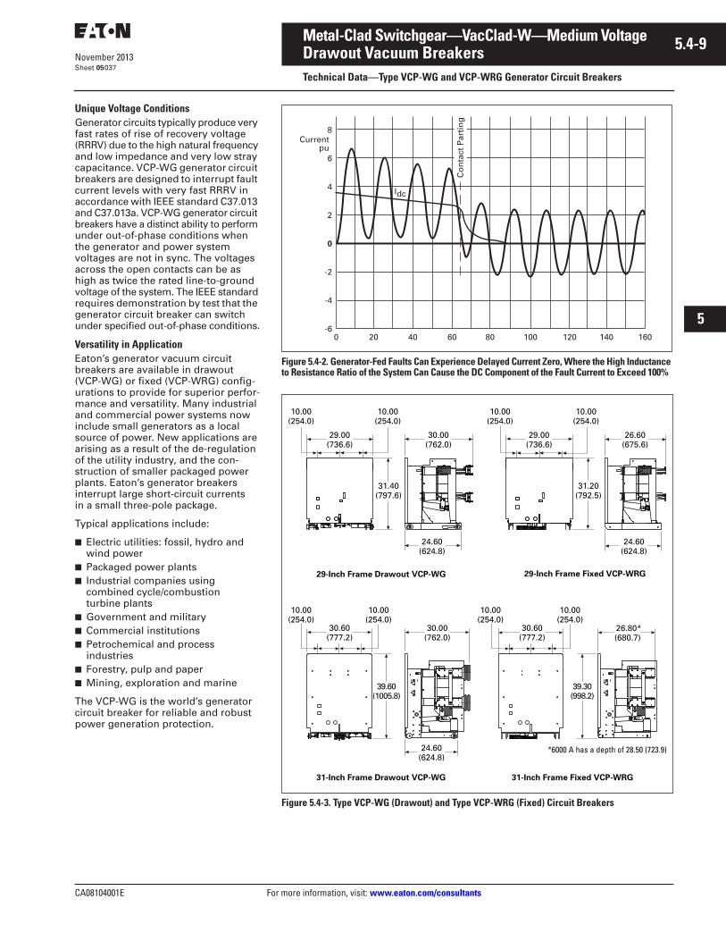
CA08104001E For more information, visit: www.eaton.com/consultants
5.4-9November 2013
Metal-Clad Switchgear—VacClad-W—Medium Voltage
i
ii
1
2
3
4
5
6
7
8
9
10
11
12
13
14
15
16
17
18
19
20
21
Sheet 05
Drawout Vacuum BreakersTechnical Data—Type VCP-WG and VCP-WRG Generator Circuit Breakers
037
Unique Voltage Conditions Generator circuits typically produce very fast rates of rise of recovery voltage (RRRV) due to the high natural frequency and low impedance and very low stray capacitance. VCP-WG generator circuit breakers are designed to interrupt fault current levels with very fast RRRV in accordance with IEEE standard C37.013 and C37.013a. VCP-WG generator circuit breakers have a distinct ability to perform under out-of-phase conditions when the generator and power system voltages are not in sync. The voltages across the open contacts can be as high as twice the rated line-to-ground voltage of the system. The IEEE standard requires demonstration by test that the generator circuit breaker can switch under specified out-of-phase conditions.
Versatility in ApplicationEaton’s generator vacuum circuit breakers are available in drawout (VCP-WG) or fixed (VCP-WRG) config-urations to provide for superior perfor-mance and versatility. Many industrial and commercial power systems now include small generators as a local source of power. New applications are arising as a result of the de-regulation of the utility industry, and the con-struction of smaller packaged power plants. Eaton’s generator breakers interrupt large short-circuit currents in a small three-pole package.
Typical applications include:
■ Electric utilities: fossil, hydro and wind power
■ Packaged power plants■ Industrial companies using
combined cycle/combustion turbine plants
■ Government and military■ Commercial institutions■ Petrochemical and process
industries■ Forestry, pulp and paper■ Mining, exploration and marine
The VCP-WG is the world’s generator circuit breaker for reliable and robust power generation protection.
Figure 5.4-2. Generator-Fed Faults Can Experience Delayed Current Zero, Where the High Inductance to Resistance Ratio of the System Can Cause the DC Component of the Fault Current to Exceed 100%
Figure 5.4-3. Type VCP-WG (Drawout) and Type VCP-WRG (Fixed) Circuit Breakers
Currentpu
0 20 40 60 80 100 120 140 160
8
6
4
2
0
-2
-4
-6
Co
nta
ct P
arti
ng
Idc
29-Inch Frame Drawout VCP-WG 29-Inch Frame Fixed VCP-WRG
10.00(254.0)
29.00(736.6)
10.00(254.0)
30.00(762.0)
24.60(624.8)
24.60(624.8)
10.00(254.0)
29.00(736.6)
10.00(254.0)
26.60(675.6)
31.20(792.5)
31.40(797.6)
31-Inch Frame Drawout VCP-WG 31-Inch Frame Fixed VCP-WRG
26.80*(680.7)
24.60(624.8)
39.60(1005.8)
30.00(762.0)
10.00(254.0)
30.60(777.2)
39.30(998.2)
*6000 A has a depth of 28.50 (723.9)
10.00(254.0)
10.00(254.0)
30.60(777.2)
10.00(254.0)
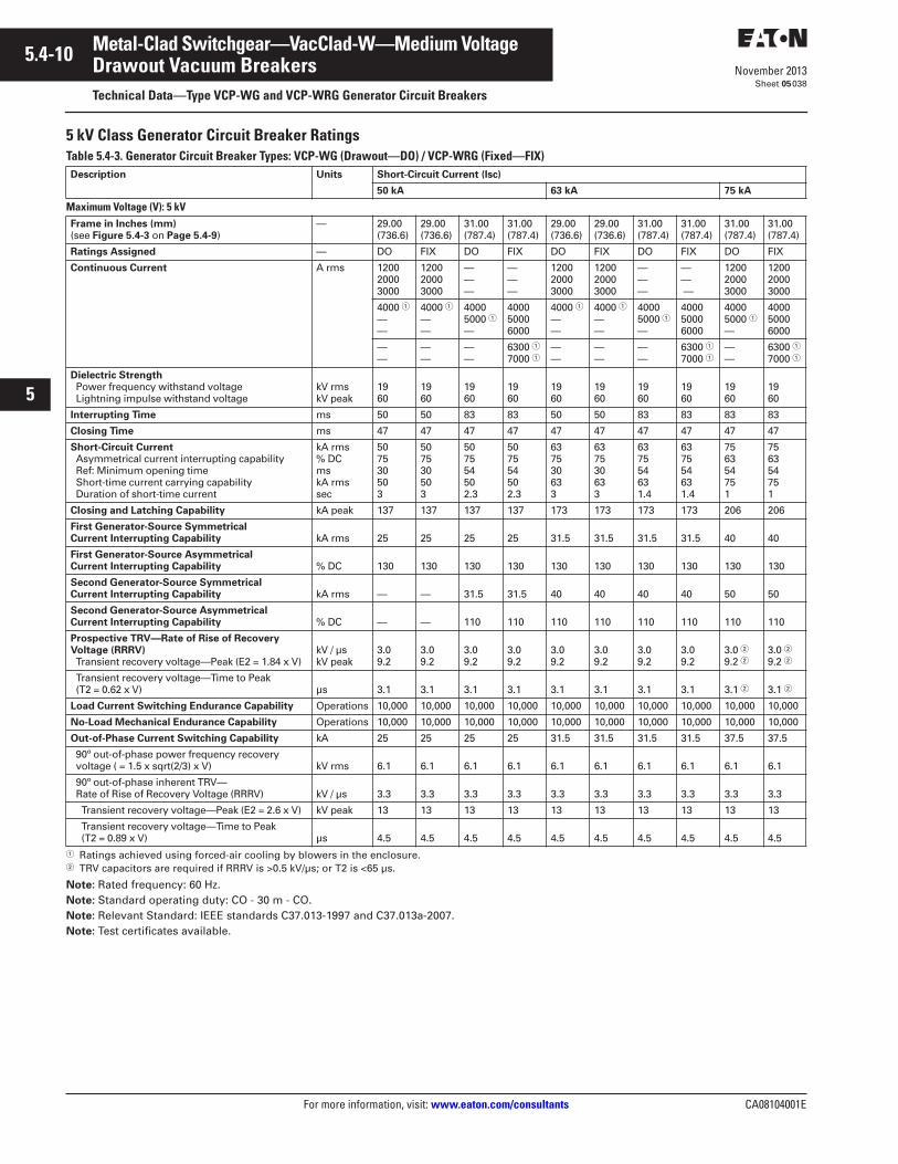
5.4-10
For more information, visit: www.eaton.com/consultants CA08104001E
November 2013
Metal-Clad Switchgear—VacClad-W—Medium Voltage
i
ii
1
2
3
4
5
6
7
8
9
10
11
12
13
14
15
16
17
18
19
20
21
Sheet 05
Drawout Vacuum BreakersTechnical Data—Type VCP-WG and VCP-WRG Generator Circuit Breakers
038
5 kV Class Generator Circuit Breaker RatingsTable 5.4-3. Generator Circuit Breaker Types: VCP-WG (Drawout—DO) / VCP-WRG (Fixed—FIX)
� Ratings achieved using forced-air cooling by blowers in the enclosure.� TRV capacitors are required if RRRV is >0.5 kV/µs; or T2 is <65 µs.
Note: Rated frequency: 60 Hz.Note: Standard operating duty: CO - 30 m - CO.Note: Relevant Standard: IEEE standards C37.013-1997 and C37.013a-2007.Note: Test certificates available.
Description Units Short-Circuit Current (Isc)
50 kA 63 kA 75 kA
Maximum Voltage (V): 5 kVFrame in Inches (mm) (see Figure 5.4-3 on Page 5.4-9)
— 29.00(736.6)
29.00(736.6)
31.00(787.4)
31.00(787.4)
29.00(736.6)
29.00(736.6)
31.00(787.4)
31.00(787.4)
31.00(787.4)
31.00(787.4)
Ratings Assigned — DO FIX DO FIX DO FIX DO FIX DO FIX
Continuous Current A rms 120020003000
120020003000
———
———
120020003000
120020003000
———
— — —
120020003000
120020003000
4000 �——
4000 �——
40005000 �—
400050006000
4000 �— —
4000 �——
40005000 �—
400050006000
40005000 �—
400050006000
——
——
——
6300 �7000 �
— —
——
——
6300 �7000 �
——
6300 �7000 �
Dielectric Strength Power frequency withstand voltage Lightning impulse withstand voltage
kV rmskV peak
1960
1960
1960
1960
1960
1960
1960
1960
1960
1960
Interrupting Time ms 50 50 83 83 50 50 83 83 83 83
Closing Time ms 47 47 47 47 47 47 47 47 47 47
Short-Circuit Current Asymmetrical current interrupting capability Ref: Minimum opening time Short-time current carrying capability Duration of short-time current
kA rms% DCmskA rmssec
507530503
507530503
507554502.3
507554502.3
637530633
637530633
637554631.4
637554631.4
756354751
756354751
Closing and Latching Capability kA peak 137 137 137 137 173 173 173 173 206 206
First Generator-Source Symmetrical Current Interrupting Capability kA rms 25 25 25 25 31.5 31.5 31.5 31.5 40 40
First Generator-Source Asymmetrical Current Interrupting Capability % DC 130 130 130 130 130 130 130 130 130 130
Second Generator-Source Symmetrical Current Interrupting Capability kA rms — — 31.5 31.5 40 40 40 40 50 50
Second Generator-Source Asymmetrical Current Interrupting Capability % DC — — 110 110 110 110 110 110 110 110
Prospective TRV—Rate of Rise of Recovery Voltage (RRRV) Transient recovery voltage—Peak (E2 = 1.84 x V)
kV / µskV peak
3.09.2
3.09.2
3.09.2
3.09.2
3.09.2
3.09.2
3.09.2
3.09.2
3.0 �9.2 �
3.0 �9.2 �
Transient recovery voltage—Time to Peak (T2 = 0.62 x V) µs 3.1 3.1 3.1 3.1 3.1 3.1 3.1 3.1 3.1 � 3.1 �
Load Current Switching Endurance Capability Operations 10,000 10,000 10,000 10,000 10,000 10,000 10,000 10,000 10,000 10,000
No-Load Mechanical Endurance Capability Operations 10,000 10,000 10,000 10,000 10,000 10,000 10,000 10,000 10,000 10,000
Out-of-Phase Current Switching Capability kA 25 25 25 25 31.5 31.5 31.5 31.5 37.5 37.5
90º out-of-phase power frequency recovery voltage ( = 1.5 x sqrt(2/3) x V) kV rms 6.1 6.1 6.1 6.1 6.1 6.1 6.1 6.1 6.1 6.1
90º out-of-phase inherent TRV— Rate of Rise of Recovery Voltage (RRRV) kV / µs 3.3 3.3 3.3 3.3 3.3 3.3 3.3 3.3 3.3 3.3
Transient recovery voltage—Peak (E2 = 2.6 x V) kV peak 13 13 13 13 13 13 13 13 13 13
Transient recovery voltage—Time to Peak (T2 = 0.89 x V) µs 4.5 4.5 4.5 4.5 4.5 4.5 4.5 4.5 4.5 4.5
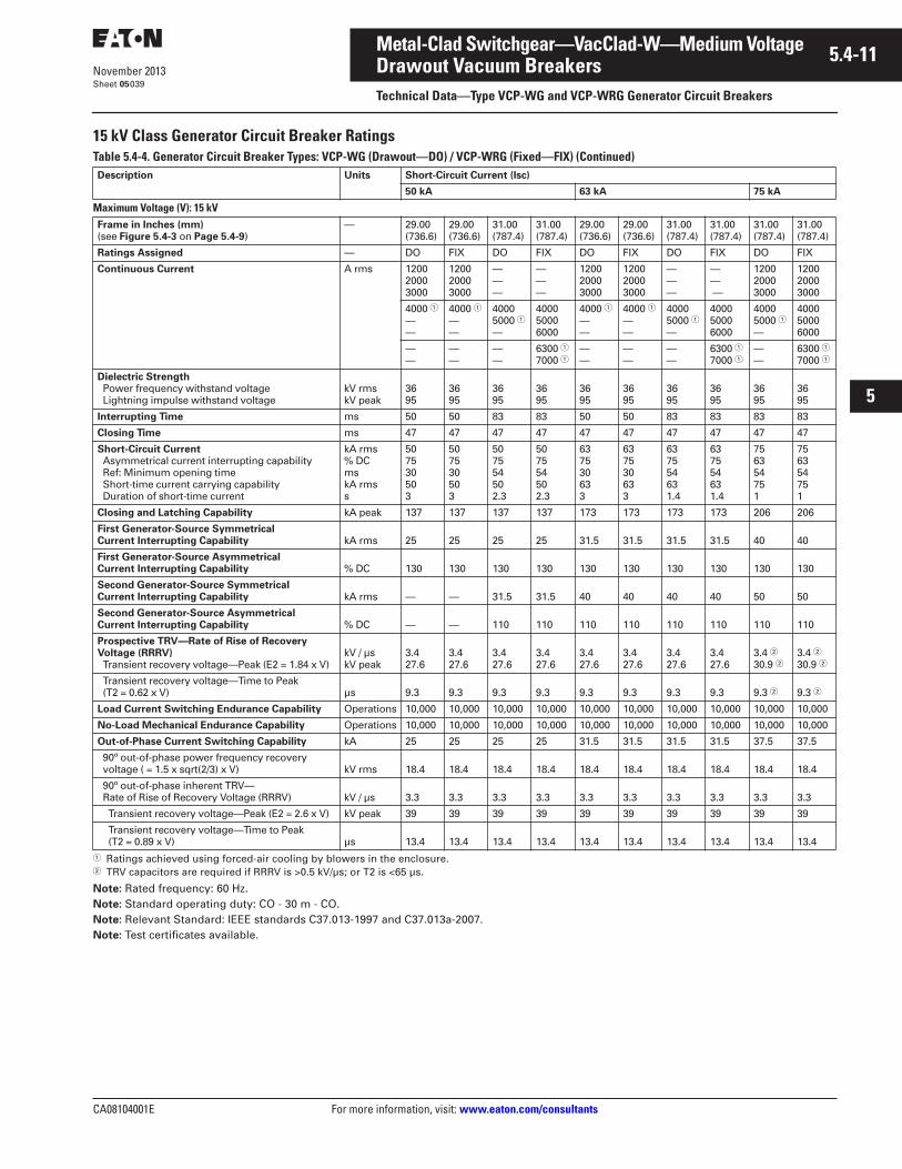
CA08104001E For more information, visit: www.eaton.com/consultants
5.4-11November 2013
Metal-Clad Switchgear—VacClad-W—Medium Voltage
i
ii
1
2
3
4
5
6
7
8
9
10
11
12
13
14
15
16
17
18
19
20
21
Sheet 05
Drawout Vacuum BreakersTechnical Data—Type VCP-WG and VCP-WRG Generator Circuit Breakers
039
15 kV Class Generator Circuit Breaker RatingsTable 5.4-4. Generator Circuit Breaker Types: VCP-WG (Drawout—DO) / VCP-WRG (Fixed—FIX) (Continued)
� Ratings achieved using forced-air cooling by blowers in the enclosure.� TRV capacitors are required if RRRV is >0.5 kV/µs; or T2 is <65 µs.
Note: Rated frequency: 60 Hz.Note: Standard operating duty: CO - 30 m - CO.Note: Relevant Standard: IEEE standards C37.013-1997 and C37.013a-2007.Note: Test certificates available.
Description Units Short-Circuit Current (Isc)
50 kA 63 kA 75 kA
Maximum Voltage (V): 15 kVFrame in Inches (mm) (see Figure 5.4-3 on Page 5.4-9)
— 29.00(736.6)
29.00(736.6)
31.00(787.4)
31.00(787.4)
29.00(736.6)
29.00(736.6)
31.00(787.4)
31.00(787.4)
31.00(787.4)
31.00(787.4)
Ratings Assigned — DO FIX DO FIX DO FIX DO FIX DO FIX
Continuous Current A rms 120020003000
120020003000
———
———
120020003000
120020003000
———
— — —
120020003000
120020003000
4000 �——
4000 �——
40005000 �—
400050006000
4000 �— —
4000 �——
40005000 �—
400050006000
40005000 �—
400050006000
——
——
——
6300 �7000 �
— —
——
——
6300 �7000 �
——
6300 �7000 �
Dielectric Strength Power frequency withstand voltage Lightning impulse withstand voltage
kV rmskV peak
3695
3695
3695
3695
3695
3695
3695
3695
3695
3695
Interrupting Time ms 50 50 83 83 50 50 83 83 83 83
Closing Time ms 47 47 47 47 47 47 47 47 47 47
Short-Circuit Current Asymmetrical current interrupting capability Ref: Minimum opening time Short-time current carrying capability Duration of short-time current
kA rms% DCmskA rmss
507530503
507530503
507554502.3
507554502.3
637530633
637530633
637554631.4
637554631.4
756354751
756354751
Closing and Latching Capability kA peak 137 137 137 137 173 173 173 173 206 206
First Generator-Source Symmetrical Current Interrupting Capability kA rms 25 25 25 25 31.5 31.5 31.5 31.5 40 40
First Generator-Source Asymmetrical Current Interrupting Capability % DC 130 130 130 130 130 130 130 130 130 130
Second Generator-Source Symmetrical Current Interrupting Capability kA rms — — 31.5 31.5 40 40 40 40 50 50
Second Generator-Source Asymmetrical Current Interrupting Capability % DC — — 110 110 110 110 110 110 110 110
Prospective TRV—Rate of Rise of Recovery Voltage (RRRV) Transient recovery voltage—Peak (E2 = 1.84 x V)
kV / µskV peak
3.427.6
3.427.6
3.427.6
3.427.6
3.427.6
3.427.6
3.427.6
3.427.6
3.4 �30.9 �
3.4 �30.9 �
Transient recovery voltage—Time to Peak (T2 = 0.62 x V) µs 9.3 9.3 9.3 9.3 9.3 9.3 9.3 9.3 9.3 � 9.3 �
Load Current Switching Endurance Capability Operations 10,000 10,000 10,000 10,000 10,000 10,000 10,000 10,000 10,000 10,000
No-Load Mechanical Endurance Capability Operations 10,000 10,000 10,000 10,000 10,000 10,000 10,000 10,000 10,000 10,000
Out-of-Phase Current Switching Capability kA 25 25 25 25 31.5 31.5 31.5 31.5 37.5 37.5
90º out-of-phase power frequency recovery voltage ( = 1.5 x sqrt(2/3) x V) kV rms 18.4 18.4 18.4 18.4 18.4 18.4 18.4 18.4 18.4 18.4
90º out-of-phase inherent TRV— Rate of Rise of Recovery Voltage (RRRV) kV / µs 3.3 3.3 3.3 3.3 3.3 3.3 3.3 3.3 3.3 3.3
Transient recovery voltage—Peak (E2 = 2.6 x V) kV peak 39 39 39 39 39 39 39 39 39 39
Transient recovery voltage—Time to Peak (T2 = 0.89 x V) µs 13.4 13.4 13.4 13.4 13.4 13.4 13.4 13.4 13.4 13.4
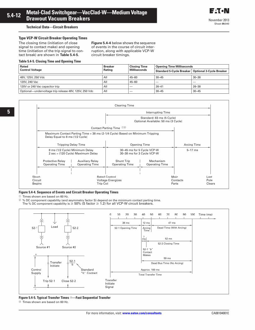
5.4-12
For more information, visit: www.eaton.com/consultants CA08104001E
November 2013
Metal-Clad Switchgear—VacClad-W—Medium Voltage
i
ii
1
2
3
4
5
6
7
8
9
10
11
12
13
14
15
16
17
18
19
20
21
Sheet 05
Drawout Vacuum BreakersTechnical Data—Circuit Breakers
040
Type VCP-W Circuit Breaker Operating TimesThe closing time (initiation of close signal to contact make) and opening time (initiation of the trip signal to con-tact break) are shown in Table 5.4-5.
Figure 5.4-4 below shows the sequence of events in the course of circuit inter-ruption, along with applicable VCP-W circuit breaker timings.
Table 5.4-5. Closing Time and Opening Time
Figure 5.4-4. Sequence of Events and Circuit Breaker Operating Times� Times shown are based on 60 Hz.� % DC component capability (and asymmetry factor S) depend on the minimum contact parting time.
The % DC component capability is 50% (S factor 1.2) for all VCP-W circuit breakers.
Figure 5.4-5. Typical Transfer Times �—Fast Sequential Transfer� Times shown are based on 60 Hz.
Rated Control Voltage
Breaker Rating
Closing Time Milliseconds
Opening Time Milliseconds
Standard 5-Cycle Breaker Optional 3-Cycle Breaker
48V, 125V, 250 Vdc All 45–60 30–45 30–38
120V, 240 Vac All 45–60 — —
120V or 240 Vac capacitor trip All — 26–41 26–38
Optional—undervoltage trip release 48V, 125V, 250 Vdc All — 30–45 30–45
Clearing Time
Interrupting Time
Contact Parting Time
Tripping Delay Time Opening Time
Shunt TripOperating Time
MechanismOperating Time
Protective RelayOperating Time
Auxiliary RelayOperating Time
Standard: 83 ms (5 Cycle)Optional Available: 50 ms (3 Cycle)
Maximum Contact Parting Time = 38 ms (2-1/4 Cycle) Based on Minimum TrippingDelay Equal to 8 ms (1/2 Cycle)
8 ms (1/2 Cycle) Minimum Delay2 sec = (120 Cycle) Maximum Delay
30–45 ms for 5 Cycle VCP-W30–38 ms for 3 Cycle VCP-W
Arcing Time
5–17 ms
Short-CircuitBegins
Rated ControlVoltage EnergizesTrip Coil
LastPoleClears
MainContactsParts
��
52-1 Opening Time
Trip 52-1
ControlSupply
Source #1
52-1
Close 52-2
Source #2
TransferInitiate
52-1b
Load 52-2
Standard”b“ Contact
TransferInitiateSignal
0 10
Dead Time (With Arcing)
90
52-1 “ ”
Makes
5030
38 ms
20
7ms
ArcingTime
12 ms
40
47 ms
7060 80 Time (ms)100
–
+
52-2 Closing Time
52 ms
Dead Bus Time (No Arcing)
59 ms
Total Transfer Time
Approx. 100 ms
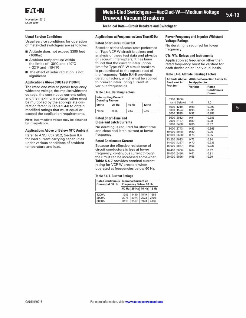
CA08104001E For more information, visit: www.eaton.com/consultants
5.4-13November 2013
Metal-Clad Switchgear—VacClad-W—Medium Voltage
i
ii
1
2
3
4
5
6
7
8
9
10
11
12
13
14
15
16
17
18
19
20
21
Sheet 05
Drawout Vacuum BreakersTechnical Data—Circuit Breakers and Switchgear
041
Usual Service ConditionsUsual service conditions for operation of metal-clad switchgear are as follows:
■ Altitude does not exceed 3300 feet (1000m)
■ Ambient temperature within the limits of –30°C and +40ºC (–22°F and +104°F)
■ The effect of solar radiation is notsignificant
Applications Above 3300 Feet (1006m)The rated one-minute power frequency withstand voltage, the impulse withstand voltage, the continuous current rating and the maximum voltage rating must be multiplied by the appropriate cor-rection factor in Table 5.4-8 to obtain modified ratings that must equal or exceed the application requirements.
Note: Intermediate values may be obtained by interpolation.
Applications Above or Below 40°C AmbientRefer to ANSI C37.20.2, Section 8.4 for load current-carrying capabilities under various conditions of ambient temperature and load.
Applications at Frequencies Less Than 60 Hz
Rated Short-Circuit CurrentBased on series of actual tests performed on Type VCP-W circuit breakers and analysis of these test data and physics of vacuum interrupters, it has been found that the current interruption limit for Type VCP-W circuit breakers is proportional to the square root of the frequency. Table 5.4-6 provides derating factors, which must be applied to breaker interrupting current at various frequencies.
Table 5.4-6. Derating Factors
Rated Short-Time and Close and Latch CurrentsNo derating is required for short time and close and latch current at lower frequency.
Rated Continuous CurrentBecause the effective resistance of circuit conductors is less at lower frequency, continuous current through the circuit can be increased somewhat. Table 5.4-7 provides nominal current rating for VCP-W breakers when operated at frequencies below 60 Hz.
Table 5.4-7. Current Ratings
Power Frequency and Impulse Withstand Voltage RatingsNo derating is required for lower frequency.
CTs, VTs, Relays and InstrumentsApplication at frequency other than rated frequency must be verified for each device on an individual basis.
Table 5.4-8. Altitude Derating Factors
Interrupting CurrentDerating Factors
50 Hz 25 Hz 16 Hz 12 Hz
None 0.65 0.52 0.45
Rated Continuous Current at 60 Hz
Nominal Current at Frequency Below 60 Hz
50 Hz 25 Hz 16 Hz 12 Hz
1200A2000A3000A
124320753119
141023743597
151925733923
158927034139
Altitude AboveSea Level inFeet (m)
Altitude Correction Factor to be Applied to:
Voltage Rated ContinuousCurrent
3300 (1006) (and Below) 1.0 1.0
4000 (1219) 5000 (1524) 6000 (1829)
0.980.950.92
0.9950.9910.987
6600 (2012) 7000 (2137) 8000 (2438)
0.910.890.86
0.9850.980.97
9000 (2743)10,000 (3048)12,000 (3658)
0.830.800.75
0.9650.960.95
13,200 (4023)14,000 (4267)16,000 (4877)
0.720.700.65
0.94 0.9350.925
16,400 (5000)18,000 (5486)20,000 (6096)
0.640.610.56
0.920.910.90
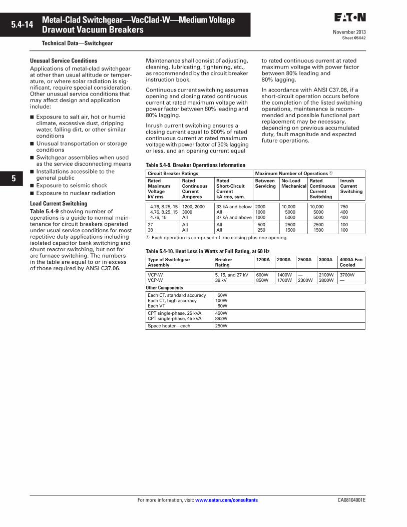
5.4-14
For more information, visit: www.eaton.com/consultants CA08104001E
November 2013
Metal-Clad Switchgear—VacClad-W—Medium Voltage
i
ii
1
2
3
4
5
6
7
8
9
10
11
12
13
14
15
16
17
18
19
20
21
Sheet 05
Drawout Vacuum BreakersTechnical Data—Switchgear
042
Unusual Service ConditionsApplications of metal-clad switchgear at other than usual altitude or temper-ature, or where solar radiation is sig-nificant, require special consideration. Other unusual service conditions that may affect design and application include:
■ Exposure to salt air, hot or humid climate, excessive dust, dripping water, falling dirt, or other similar conditions
■ Unusual transportation or storage conditions
■ Switchgear assemblies when used as the service disconnecting means
■ Installations accessible to the general public
■ Exposure to seismic shock■ Exposure to nuclear radiation
Load Current SwitchingTable 5.4-9 showing number of operations is a guide to normal main-tenance for circuit breakers operated under usual service conditions for most repetitive duty applications including isolated capacitor bank switching and shunt reactor switching, but not for arc furnace switching. The numbers in the table are equal to or in excess of those required by ANSI C37.06.
Maintenance shall consist of adjusting, cleaning, lubricating, tightening, etc., as recommended by the circuit breaker instruction book.
Continuous current switching assumes opening and closing rated continuous current at rated maximum voltage with power factor between 80% leading and 80% lagging.
Inrush current switching ensures a closing current equal to 600% of rated continuous current at rated maximum voltage with power factor of 30% lagging or less, and an opening current equal
to rated continuous current at rated maximum voltage with power factor between 80% leading and 80% lagging.
In accordance with ANSI C37.06, if a short-circuit operation occurs before the completion of the listed switching operations, maintenance is recom-mended and possible functional part replacement may be necessary, depending on previous accumulated duty, fault magnitude and expected future operations.
Table 5.4-9. Breaker Operations Information
� Each operation is comprised of one closing plus one opening.
Table 5.4-10. Heat Loss in Watts at Full Rating, at 60 Hz
Circuit Breaker Ratings Maximum Number of Operations �
Rated Maximum Voltage kV rms
RatedContinuous Current Amperes
Rated Short-CircuitCurrent kA rms, sym.
BetweenServicing
No-Load Mechanical
Rated ContinuousCurrent Switching
Inrush Current Switching
4.76, 8.25, 15 4.76, 8.25, 15 4.76, 15
1200, 20003000All
33 kA and belowAll37 kA and above
200010001000
10,000 5000 5000
10,000 5000 5000
750400400
2738
AllAll
AllAll
500 250
2500 1500
2500 1500
100100
Type of Switchgear Assembly
Breaker Rating
1200A 2000A 2500A 3000A 4000A Fan Cooled
VCP-WVCP-W
5, 15, and 27 kV38 kV
600W850W
1400W1700W
—2300W
2100W3800W
3700W—
Other ComponentsEach CT, standard accuracyEach CT, high accuracyEach VT
50W100W 60W
CPT single-phase, 25 kVACPT single-phase, 45 kVA
450W892W
Space heater—each 250W
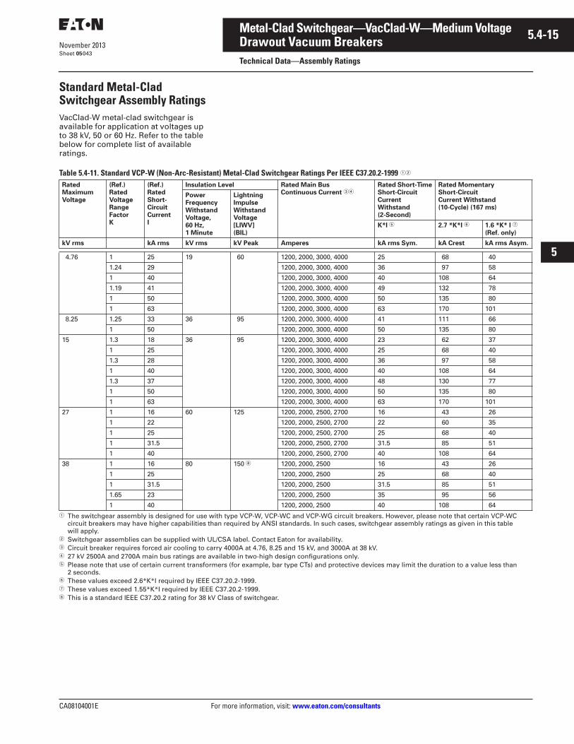
CA08104001E For more information, visit: www.eaton.com/consultants
5.4-15November 2013
Metal-Clad Switchgear—VacClad-W—Medium Voltage
i
ii
1
2
3
4
5
6
7
8
9
10
11
12
13
14
15
16
17
18
19
20
21
Sheet 05
Drawout Vacuum BreakersTechnical Data—Assembly Ratings
043
Standard Metal-Clad Switchgear Assembly RatingsVacClad-W metal-clad switchgear is available for application at voltages up to 38 kV, 50 or 60 Hz. Refer to the table below for complete list of available ratings.
Table 5.4-11. Standard VCP-W (Non-Arc-Resistant) Metal-Clad Switchgear Ratings Per IEEE C37.20.2-1999 ��
� The switchgear assembly is designed for use with type VCP-W, VCP-WC and VCP-WG circuit breakers. However, please note that certain VCP-WC circuit breakers may have higher capabilities than required by ANSI standards. In such cases, switchgear assembly ratings as given in this table will apply.
� Switchgear assemblies can be supplied with UL/CSA label. Contact Eaton for availability.� Circuit breaker requires forced air cooling to carry 4000A at 4.76, 8.25 and 15 kV, and 3000A at 38 kV.� 27 kV 2500A and 2700A main bus ratings are available in two-high design configurations only.� Please note that use of certain current transformers (for example, bar type CTs) and protective devices may limit the duration to a value less than
2 seconds.� These values exceed 2.6*K*I required by IEEE C37.20.2-1999.� These values exceed 1.55*K*I required by IEEE C37.20.2-1999.� This is a standard IEEE C37.20.2 rating for 38 kV Class of switchgear.
RatedMaximumVoltage
(Ref.)RatedVoltageRangeFactorK
(Ref.)RatedShort-CircuitCurrentI
Insulation Level Rated Main BusContinuous Current ��
Rated Short-Time Short-CircuitCurrent Withstand(2-Second)
Rated Momentary Short-CircuitCurrent Withstand (10-Cycle) (167 ms)
PowerFrequencyWithstandVoltage, 60 Hz,1 Minute
LightningImpulseWithstandVoltage[LIWV] (BIL)
K*I � 2.7 *K*I � 1.6 *K* I �
(Ref. only)
kV rms kA rms kV rms kV Peak Amperes kA rms Sym. kA Crest kA rms Asym.
4.76 1 25 19 60 1200, 2000, 3000, 4000 25 68 40
1.24 29 1200, 2000, 3000, 4000 36 97 58
1 40 1200, 2000, 3000, 4000 40 108 64
1.19 41 1200, 2000, 3000, 4000 49 132 78
1 50 1200, 2000, 3000, 4000 50 135 80
1 63 1200, 2000, 3000, 4000 63 170 101
8.25 1.25 33 36 95 1200, 2000, 3000, 4000 41 111 66
1 50 1200, 2000, 3000, 4000 50 135 80
15 1.3 18 36 95 1200, 2000, 3000, 4000 23 62 37
1 25 1200, 2000, 3000, 4000 25 68 40
1.3 28 1200, 2000, 3000, 4000 36 97 58
1 40 1200, 2000, 3000, 4000 40 108 64
1.3 37 1200, 2000, 3000, 4000 48 130 77
1 50 1200, 2000, 3000, 4000 50 135 80
1 63 1200, 2000, 3000, 4000 63 170 101
27 1 16 60 125 1200, 2000, 2500, 2700 16 43 26
1 22 1200, 2000, 2500, 2700 22 60 35
1 25 1200, 2000, 2500, 2700 25 68 40
1 31.5 1200, 2000, 2500, 2700 31.5 85 51
1 40 1200, 2000, 2500, 2700 40 108 64
38 1 16 80 150 � 1200, 2000, 2500 16 43 26
1 25 1200, 2000, 2500 25 68 40
1 31.5 1200, 2000, 2500 31.5 85 51
1.65 23 1200, 2000, 2500 35 95 56
1 40 1200, 2000, 2500 40 108 64
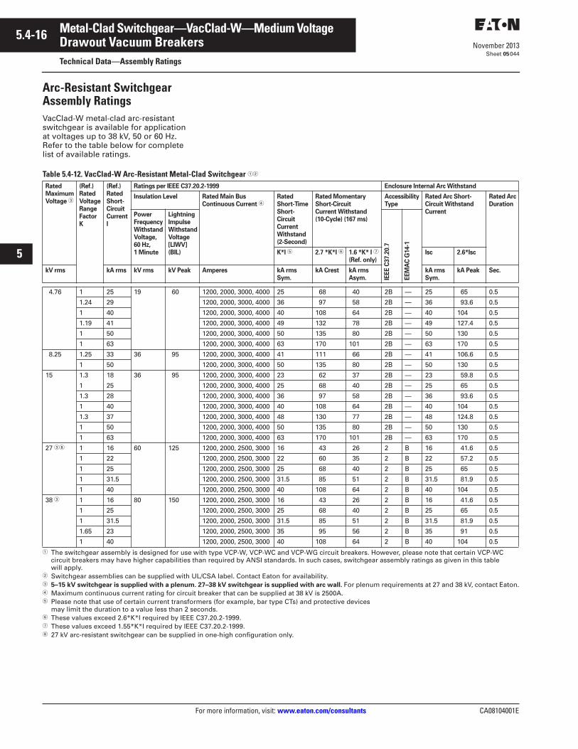
5.4-16
For more information, visit: www.eaton.com/consultants CA08104001E
November 2013
Metal-Clad Switchgear—VacClad-W—Medium Voltage
i
ii
1
2
3
4
5
6
7
8
9
10
11
12
13
14
15
16
17
18
19
20
21
Sheet 05
Drawout Vacuum BreakersTechnical Data—Assembly Ratings
044
Arc-Resistant Switchgear Assembly RatingsVacClad-W metal-clad arc-resistant switchgear is available for application at voltages up to 38 kV, 50 or 60 Hz. Refer to the table below for complete list of available ratings.
Table 5.4-12. VacClad-W Arc-Resistant Metal-Clad Switchgear ��
� The switchgear assembly is designed for use with type VCP-W, VCP-WC and VCP-WG circuit breakers. However, please note that certain VCP-WC circuit breakers may have higher capabilities than required by ANSI standards. In such cases, switchgear assembly ratings as given in this table will apply.
� Switchgear assemblies can be supplied with UL/CSA label. Contact Eaton for availability.� 5–15 kV switchgear is supplied with a plenum. 27–38 kV switchgear is supplied with arc wall. For plenum requirements at 27 and 38 kV, contact Eaton.� Maximum continuous current rating for circuit breaker that can be supplied at 38 kV is 2500A.� Please note that use of certain current transformers (for example, bar type CTs) and protective devices
may limit the duration to a value less than 2 seconds.� These values exceed 2.6*K*I required by IEEE C37.20.2-1999.� These values exceed 1.55*K*I required by IEEE C37.20.2-1999.� 27 kV arc-resistant switchgear can be supplied in one-high configuration only.
RatedMaximumVoltage �
(Ref.)RatedVoltageRangeFactorK
(Ref.)RatedShort-CircuitCurrentI
Ratings per IEEE C37.20.2-1999 Enclosure Internal Arc Withstand
Insulation Level Rated Main BusContinuous Current �
Rated Short-Time Short-CircuitCurrent Withstand (2-Second)
Rated Momentary Short-CircuitCurrent Withstand (10-Cycle) (167 ms)
AccessibilityType
Rated Arc Short-Circuit Withstand Current
Rated ArcDuration
PowerFrequencyWithstandVoltage, 60 Hz,1 Minute
LightningImpulseWithstandVoltage[LIWV](BIL)
IEE
E C
37.2
0.7
EE
MA
C G
14-1
K*I � 2.7 *K*I � 1.6 *K* I �
(Ref. only)Isc 2.6*Isc
kV rms kA rms kV rms kV Peak Amperes kA rms Sym.
kA Crest kA rmsAsym.
kA rms Sym.
kA Peak Sec.
4.76 1 25 19 60 1200, 2000, 3000, 4000 25 68 40 2B — 25 65 0.5
1.24 29 1200, 2000, 3000, 4000 36 97 58 2B — 36 93.6 0.5
1 40 1200, 2000, 3000, 4000 40 108 64 2B — 40 104 0.5
1.19 41 1200, 2000, 3000, 4000 49 132 78 2B — 49 127.4 0.5
1 50 1200, 2000, 3000, 4000 50 135 80 2B — 50 130 0.5
1 63 1200, 2000, 3000, 4000 63 170 101 2B — 63 170 0.5
8.25 1.25 33 36 95 1200, 2000, 3000, 4000 41 111 66 2B — 41 106.6 0.5
1 50 1200, 2000, 3000, 4000 50 135 80 2B — 50 130 0.5
15 1.3 18 36 95 1200, 2000, 3000, 4000 23 62 37 2B — 23 59.8 0.5
1 25 1200, 2000, 3000, 4000 25 68 40 2B — 25 65 0.5
1.3 28 1200, 2000, 3000, 4000 36 97 58 2B — 36 93.6 0.5
1 40 1200, 2000, 3000, 4000 40 108 64 2B — 40 104 0.5
1.3 37 1200, 2000, 3000, 4000 48 130 77 2B — 48 124.8 0.5
1 50 1200, 2000, 3000, 4000 50 135 80 2B — 50 130 0.5
1 63 1200, 2000, 3000, 4000 63 170 101 2B — 63 170 0.5
27 �� 1 16 60 125 1200, 2000, 2500, 3000 16 43 26 2 B 16 41.6 0.5
1 22 1200, 2000, 2500, 3000 22 60 35 2 B 22 57.2 0.5
1 25 1200, 2000, 2500, 3000 25 68 40 2 B 25 65 0.5
1 31.5 1200, 2000, 2500, 3000 31.5 85 51 2 B 31.5 81.9 0.5
1 40 1200, 2000, 2500, 3000 40 108 64 2 B 40 104 0.5
38 � 1 16 80 150 1200, 2000, 2500, 3000 16 43 26 2 B 16 41.6 0.5
1 25 1200, 2000, 2500, 3000 25 68 40 2 B 25 65 0.5
1 31.5 1200, 2000, 2500, 3000 31.5 85 51 2 B 31.5 81.9 0.5
1.65 23 1200, 2000, 2500, 3000 35 95 56 2 B 35 91 0.5
1 40 1200, 2000, 2500, 3000 40 108 64 2 B 40 104 0.5
CA08104001E For more information, visit: www.eaton.com/consultants
5.4-17November 2013
Metal-Clad Switchgear—VacClad-W—Medium Voltage
i
ii
1
2
3
4
5
6
7
8
9
10
11
12
13
14
15
16
17
18
19
20
21
Sheet 05
Drawout Vacuum BreakersTechnical Data—Surge Protection
045
Surge ProtectionEaton’s VacClad-W metal-clad switch-gear is applied over a broad range of circuits, and is one of the many types of equipment in the total system. The distribution system can be subject to voltage transients caused by lighting or switching surges.
Recognizing that distribution system can be subject to voltage transients caused by lighting or switching, the industry has developed standards to provide guidelines for surge protection of electrical equipment. Those guide-lines should be used in design and protection of electrical distribution systems independent of the circuit breaker interrupting medium. The industry standards are:
ANSI C62Guides and Standards for Surge Protection
IEEE 242—Buff BookIEEE Recommended Practice for Protection and Coordination of Industrial and Commercial Power Systems
IEEE 141—Red BookRecommended Practice for Electric Power Distribution forIndustrial Plants
IEEE C37.20.2Standards for Metal-Clad Switchgear
Eaton’s medium voltage metal-clad and metal-enclosed switchgear that uses vacuum circuit breakers is applied over a broad range of circuits. It is one of the many types of equipment in the total distribution system. Whenever a switching device is opened or closed, certain interactions of the power system elements with the switching device can cause high frequency voltage transients in the system. Due to the wide range of applications and variety of ratings used for different elements in the power systems, a given circuit may or may not require surge protec-tion. Therefore, Eaton does not include surge protection as standard with its metal-clad or metal-enclosed medium voltage switchgear. The user exercises the options as to the type and extent of the surge protection necessary depending on the individual circuit characteristics and cost considerations.
The following are Eaton’s recommen-dations for surge protection of medium voltage equipment. Please note these recommendations are valid when using Eaton’s vacuum breakers only.
Surge Protection Recommendations:Note: The abbreviation Protec Z used in the text below refers to Surge Protection Device manufactured by NTSA. An equiva-lent device offered by other manufacturers, such as Type EHZ by ABB, can also be used.
1. For circuits exposed to lightning, surge arresters should be applied in line with Industry standard practices.
2. Transformers
a. Close-coupled to medium voltage primary breaker:Provide transients surge pro-tection, such as surge arrester in parallel with RC snubber, or Protec Z. The surge protection device selected should be located and connected at the transformer primary terminals or it can be located inside the switchgear and connected on the transformer side of the primary breaker.
b. Cable-connected to medium voltage primary breaker: Provide transient surge protec-tion, such as surge arrester in parallel with RC snubber, or Protec Z for transformers con-nected by cables with lengths up to 75 feet. The surge protec-tion device should be located and connected at the trans-former terminals. No surge protection is needed for trans-formers with lightning impulse withstand ratings equal to that of the switchgear and connected to the switchgear by cables at least 75 feet or longer. For transformers with lower BIL, provide surge arrester in parallel with RC snubber or Protec Z.
RC snubber and/or Protec Z damp internal transformer resonance:
The natural frequency of transformer windings can under some circumstances be excited to resonate. Transformer windings in resonance can produce elevated internal voltages that produce insulation damage or failure. An RC snubber or a Protec Z applied at the transformer terminals as indicated above can damp internal winding resonance and prevent the production of damaging elevated internal voltages. This is typically required where rectifiers, UPS or similar electronic equipment is on the transformer secondary.
3. Arc-Furnace Transformers—Provide surge arrester in parallel with RC snubber, or Protec Z at the transformer terminals.
4. Motors—Provide surge arrester in parallel with RC snubber, or Protec Z at the motor terminals. For those motors using VFDs, surge protection should be applied and precede the VFD devices as well.
5. Generators—Provide station class surge arrester in parallel with RC snubber, or Protec Z at the generator terminals.
6. Capacitor Switching—No surge protection is required. Make sure that the capacitor’s lightning impulse withstand rating is equal to that of the switchgear.
7. Shunt Reactor Switching—Provide surge arrester in parallel with RC snubber, or Protec Z at the reactor terminals.
8. Motor Starting Reactors or Reduced Voltage Auto-Transformers—Provide surge arrester in parallel with RC snubber, or Protec Z at the reactor or RVAT terminals.
9. Switching Underground Cables—Surge protection not needed.
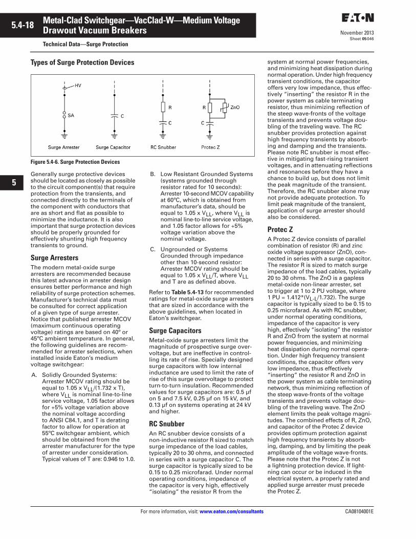
5.4-18
For more information, visit: www.eaton.com/consultants CA08104001E
November 2013
Metal-Clad Switchgear—VacClad-W—Medium Voltage
i
ii
1
2
3
4
5
6
7
8
9
10
11
12
13
14
15
16
17
18
19
20
21
Sheet 05
Drawout Vacuum BreakersTechnical Data—Surge Protection
046
Types of Surge Protection Devices
Figure 5.4-6. Surge Protection Devices
Generally surge protective devices should be located as closely as possible to the circuit component(s) that require protection from the transients, and connected directly to the terminals of the component with conductors that are as short and flat as possible to minimize the inductance. It is also important that surge protection devices should be properly grounded for effectively shunting high frequency transients to ground.
Surge ArrestersThe modern metal-oxide surge arresters are recommended because this latest advance in arrester design ensures better performance and high reliability of surge protection schemes. Manufacturer’s technical data must be consulted for correct application of a given type of surge arrester. Notice that published arrester MCOV (maximum continuous operating voltage) ratings are based on 40º or 45ºC ambient temperature. In general, the following guidelines are recom-mended for arrester selections, when installed inside Eaton’s medium voltage switchgear:
A. Solidly Grounded Systems:Arrester MCOV rating should be equal to 1.05 x VLL/(1.732 x T), where VLL is nominal line-to-line service voltage, 1.05 factor allows for +5% voltage variation above the nominal voltage according to ANSI C84.1, and T is derating factor to allow for operation at 55ºC switchgear ambient, which should be obtained from the arrester manufacturer for the type of arrester under consideration. Typical values of T are: 0.946 to 1.0.
B. Low Resistant Grounded Systems (systems grounded through resistor rated for 10 seconds):Arrester 10-second MCOV capability at 60ºC, which is obtained from manufacturer’s data, should be equal to 1.05 x VLL, where VLL is nominal line-to-line service voltage, and 1.05 factor allows for +5% voltage variation above the nominal voltage.
C. Ungrounded or Systems Grounded through impedance other than 10-second resistor:Arrester MCOV rating should be equal to 1.05 x VLL/T, where VLL and T are as defined above.
Refer to Table 5.4-13 for recommended ratings for metal-oxide surge arresters that are sized in accordance with the above guidelines, when located in Eaton’s switchgear.
Surge CapacitorsMetal-oxide surge arresters limit the magnitude of prospective surge over-voltage, but are ineffective in control-ling its rate of rise. Specially designed surge capacitors with low internal inductance are used to limit the rate of rise of this surge overvoltage to protect turn-to-turn insulation. Recommended values for surge capacitors are: 0.5 µf on 5 and 7.5 kV, 0.25 µf on 15 kV, and 0.13 µf on systems operating at 24 kV and higher.
RC SnubberAn RC snubber device consists of a non-inductive resistor R sized to match surge impedance of the load cables, typically 20 to 30 ohms, and connected in series with a surge capacitor C. The surge capacitor is typically sized to be 0.15 to 0.25 microfarad. Under normal operating conditions, impedance of the capacitor is very high, effectively “isolating” the resistor R from the
system at normal power frequencies, and minimizing heat dissipation during normal operation. Under high frequency transient conditions, the capacitor offers very low impedance, thus effec-tively “inserting” the resistor R in the power system as cable terminating resistor, thus minimizing reflection of the steep wave-fronts of the voltage transients and prevents voltage dou-bling of the traveling wave. The RC snubber provides protection against high frequency transients by absorb-ing and damping and the transients. Please note RC snubber is most effec-tive in mitigating fast-rising transient voltages, and in attenuating reflections and resonances before they have a chance to build up, but does not limit the peak magnitude of the transient. Therefore, the RC snubber alone may not provide adequate protection. To limit peak magnitude of the transient, application of surge arrester should also be considered.
Protec ZA Protec Z device consists of parallel combination of resistor (R) and zinc oxide voltage suppressor (ZnO), con-nected in series with a surge capacitor. The resistor R is sized to match surge impedance of the load cables, typically 20 to 30 ohms. The ZnO is a gapless metal-oxide non-linear arrester, set to trigger at 1 to 2 PU voltage, where 1 PU = 1.412*(VL-L/1.732). The surge capacitor is typically sized to be 0.15 to 0.25 microfarad. As with RC snubber, under normal operating conditions, impedance of the capacitor is very high, effectively “isolating” the resistor R and ZnO from the system at normal power frequencies, and minimizing heat dissipation during normal opera-tion. Under high frequency transient conditions, the capacitor offers very low impedance, thus effectively “inserting” the resistor R and ZnO in the power system as cable terminating network, thus minimizing reflection of the steep wave-fronts of the voltage transients and prevents voltage dou-bling of the traveling wave. The ZnO element limits the peak voltage magni-tudes. The combined effects of R, ZnO, and capacitor of the Protec Z device provides optimum protection against high frequency transients by absorb-ing, damping, and by limiting the peak amplitude of the voltage wave-fronts. Please note that the Protec Z is not a lightning protection device. If light-ning can occur or be induced in the electrical system, a properly rated and applied surge arrester must precede the Protec Z.
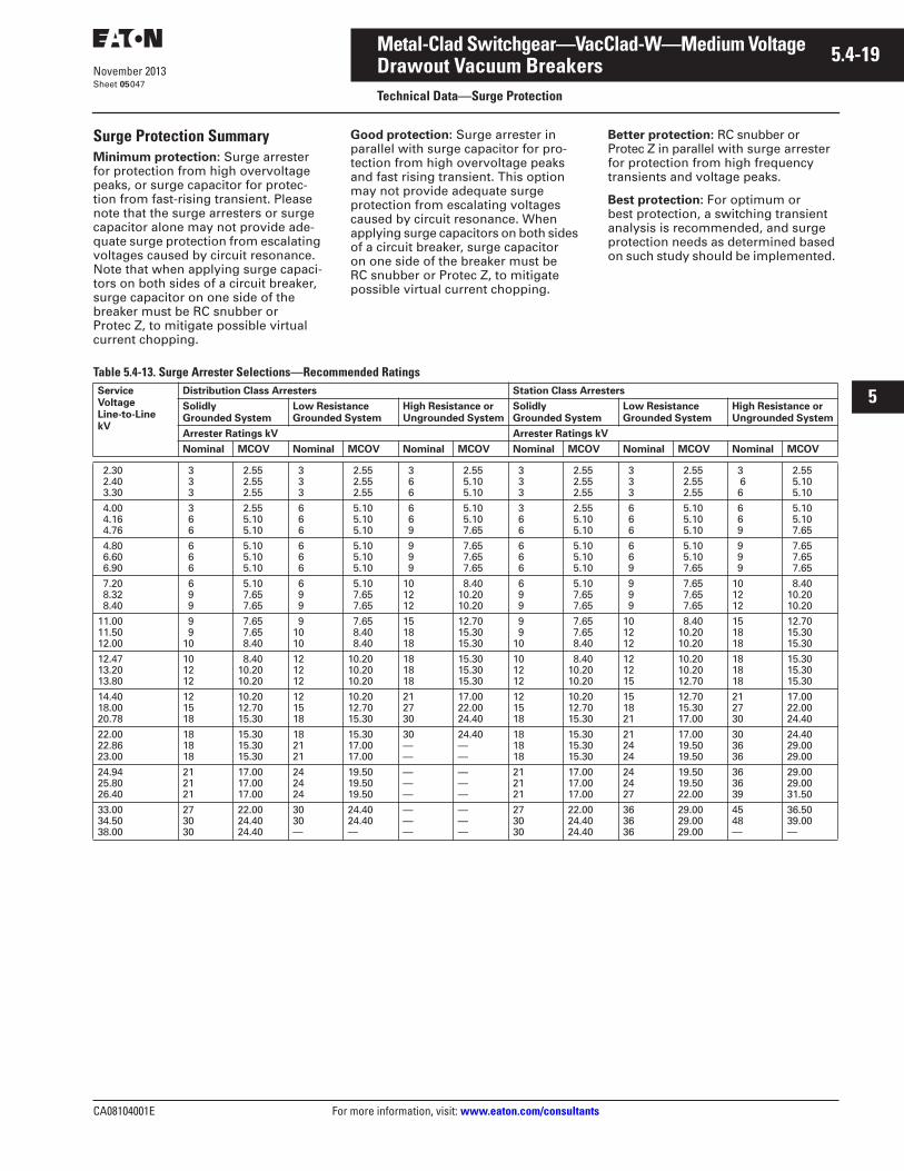
CA08104001E For more information, visit: www.eaton.com/consultants
5.4-19November 2013
Metal-Clad Switchgear—VacClad-W—Medium Voltage
i
ii
1
2
3
4
5
6
7
8
9
10
11
12
13
14
15
16
17
18
19
20
21
Sheet 05
Drawout Vacuum BreakersTechnical Data—Surge Protection
047
Surge Protection SummaryMinimum protection: Surge arrester for protection from high overvoltage peaks, or surge capacitor for protec-tion from fast-rising transient. Please note that the surge arresters or surge capacitor alone may not provide ade-quate surge protection from escalating voltages caused by circuit resonance. Note that when applying surge capaci-tors on both sides of a circuit breaker, surge capacitor on one side of the breaker must be RC snubber or Protec Z, to mitigate possible virtual current chopping.
Good protection: Surge arrester in parallel with surge capacitor for pro-tection from high overvoltage peaks and fast rising transient. This option may not provide adequate surge protection from escalating voltages caused by circuit resonance. When applying surge capacitors on both sides of a circuit breaker, surge capacitor on one side of the breaker must be RC snubber or Protec Z, to mitigate possible virtual current chopping.
Better protection: RC snubber or Protec Z in parallel with surge arrester for protection from high frequency transients and voltage peaks.
Best protection: For optimum or best protection, a switching transient analysis is recommended, and surge protection needs as determined based on such study should be implemented.
Table 5.4-13. Surge Arrester Selections—Recommended Ratings Service VoltageLine-to-Line kV
Distribution Class Arresters Station Class Arresters
Solidly Grounded System
Low ResistanceGrounded System
High Resistance orUngrounded System
Solidly Grounded System
Low ResistanceGrounded System
High Resistance orUngrounded System
Arrester Ratings kV Arrester Ratings kV
Nominal MCOV Nominal MCOV Nominal MCOV Nominal MCOV Nominal MCOV Nominal MCOV
2.30 2.40 3.30
3 3 3
2.55 2.55 2.55
3 3 3
2.55 2.55 2.55
3 6 6
2.55 5.10 5.10
3 3 3
2.55 2.55 2.55
3 3 3
2.55 2.55 2.55
3 6 6
2.55 5.10 5.10
4.00 4.16 4.76
3 6 6
2.55 5.10 5.10
6 6 6
5.10 5.10 5.10
6 6 9
5.10 5.10 7.65
3 6 6
2.55 5.10 5.10
6 6 6
5.10 5.10 5.10
6 6 9
5.10 5.10 7.65
4.80 6.60 6.90
6 6 6
5.10 5.10 5.10
6 6 6
5.10 5.10 5.10
9 9 9
7.65 7.65 7.65
6 6 6
5.10 5.10 5.10
6 6 9
5.10 5.10 7.65
9 9 9
7.65 7.65 7.65
7.20 8.32 8.40
6 9 9
5.10 7.65 7.65
6 9 9
5.10 7.65 7.65
101212
8.4010.2010.20
6 9 9
5.10 7.65 7.65
9 9 9
7.65 7.65 7.65
101212
8.4010.2010.20
11.0011.5012.00
9 910
7.65 7.65 8.40
91010
7.65 8.40 8.40
151818
12.7015.3015.30
9 910
7.65 7.65 8.40
101212
8.4010.2010.20
151818
12.7015.3015.30
12.4713.2013.80
101212
8.4010.2010.20
121212
10.2010.2010.20
181818
15.3015.3015.30
101212
8.4010.2010.20
121215
10.2010.2012.70
181818
15.3015.3015.30
14.4018.0020.78
121518
10.2012.7015.30
121518
10.2012.7015.30
212730
17.0022.0024.40
121518
10.2012.7015.30
151821
12.7015.3017.00
212730
17.0022.0024.40
22.0022.8623.00
181818
15.3015.3015.30
182121
15.3017.0017.00
30——
24.40——
181818
15.3015.3015.30
212424
17.0019.5019.50
303636
24.4029.0029.00
24.9425.8026.40
212121
17.0017.0017.00
242424
19.5019.5019.50
———
———
212121
17.0017.0017.00
242427
19.5019.5022.00
363639
29.0029.0031.50
33.0034.5038.00
273030
22.0024.4024.40
3030—
24.4024.40—
———
———
273030
22.0024.4024.40
363636
29.0029.0029.00
4548—
36.5039.00—
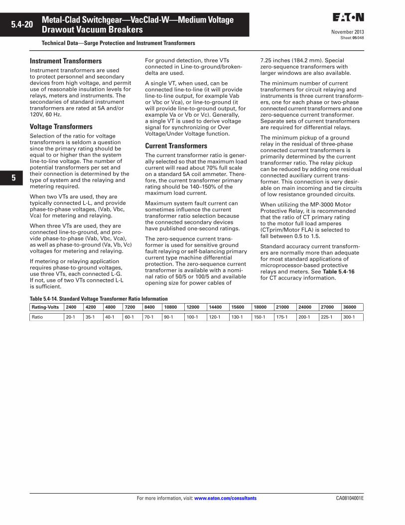
5.4-20
For more information, visit: www.eaton.com/consultants CA08104001E
November 2013
Metal-Clad Switchgear—VacClad-W—Medium Voltage
i
ii
1
2
3
4
5
6
7
8
9
10
11
12
13
14
15
16
17
18
19
20
21
Sheet 05
Drawout Vacuum BreakersTechnical Data—Surge Protection and Instrument Transformers
048
Instrument TransformersInstrument transformers are used to protect personnel and secondary devices from high voltage, and permit use of reasonable insulation levels for relays, meters and instruments. The secondaries of standard instrument transformers are rated at 5A and/or 120V, 60 Hz.
Voltage TransformersSelection of the ratio for voltage transformers is seldom a question since the primary rating should be equal to or higher than the system line-to-line voltage. The number of potential transformers per set and their connection is determined by the type of system and the relaying and metering required.
When two VTs are used, they are typically connected L-L, and provide phase-to-phase voltages, (Vab, Vbc, Vca) for metering and relaying.
When three VTs are used, they are connected line-to-ground, and pro-vide phase-to-phase (Vab, Vbc, Vca), as well as phase-to-ground (Va, Vb, Vc) voltages for metering and relaying.
If metering or relaying application requires phase-to-ground voltages, use three VTs, each connected L-G. If not, use of two VTs connected L-L is sufficient.
For ground detection, three VTs connected in Line-to-ground/broken-delta are used.
A single VT, when used, can be connected line-to-line (it will provide line-to-line output, for example Vab or Vbc or Vca), or line-to-ground (it will provide line-to-ground output, for example Va or Vb or Vc). Generally, a single VT is used to derive voltage signal for synchronizing or Over Voltage/Under Voltage function.
Current TransformersThe current transformer ratio is gener-ally selected so that the maximum load current will read about 70% full scale on a standard 5A coil ammeter. There-fore, the current transformer primary rating should be 140–150% of the maximum load current.
Maximum system fault current can sometimes influence the current transformer ratio selection because the connected secondary devices have published one-second ratings.
The zero-sequence current trans-former is used for sensitive ground fault relaying or self-balancing primary current type machine differential protection. The zero-sequence current transformer is available with a nomi-nal ratio of 50/5 or 100/5 and available opening size for power cables of
7.25 inches (184.2 mm). Special zero-sequence transformers with larger windows are also available.
The minimum number of current transformers for circuit relaying and instruments is three current transform-ers, one for each phase or two-phase connected current transformers and one zero-sequence current transformer. Separate sets of current transformers are required for differential relays.
The minimum pickup of a ground relay in the residual of three-phase connected current transformers is primarily determined by the current transformer ratio. The relay pickup can be reduced by adding one residual connected auxiliary current trans-former. This connection is very desir-able on main incoming and tie circuits of low resistance grounded circuits.
When utilizing the MP-3000 Motor Protective Relay, it is recommended that the ratio of CT primary rating to the motor full load amperes (CTprim/Motor FLA) is selected to fall between 0.5 to 1.5.
Standard accuracy current transform-ers are normally more than adequate for most standard applications of microprocessor-based protective relays and meters. See Table 5.4-16 for CT accuracy information.
Table 5.4-14. Standard Voltage Transformer Ratio Information Rating-Volts 2400 4200 4800 7200 8400 10800 12000 14400 15600 18000 21000 24000 27000 36000
Ratio 20-1 35-1 40-1 60-1 70-1 90-1 100-1 120-1 130-1 150-1 175-1 200-1 225-1 300-1
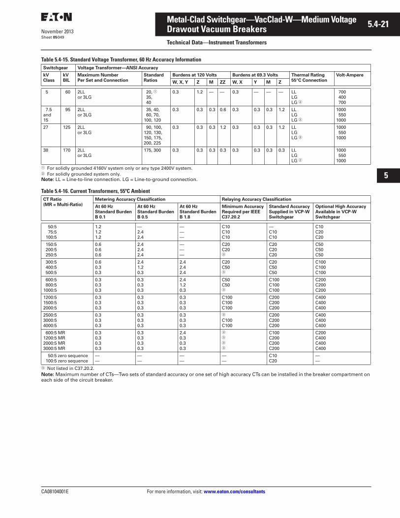
CA08104001E For more information, visit: www.eaton.com/consultants
5.4-21November 2013
Metal-Clad Switchgear—VacClad-W—Medium Voltage
i
ii
1
2
3
4
5
6
7
8
9
10
11
12
13
14
15
16
17
18
19
20
21
Sheet 05
Drawout Vacuum BreakersTechnical Data—Instrument Transformers
049
Table 5.4-15. Standard Voltage Transformer, 60 Hz Accuracy Information
� For solidly grounded 4160V system only or any type 2400V system.� For solidly grounded system only.Note: LL = Line-to-line connection. LG = Line-to-ground connection.
Table 5.4-16. Current Transformers, 55ºC Ambient
� Not listed in C37.20.2.Note: Maximum number of CTs—Two sets of standard accuracy or one set of high accuracy CTs can be installed in the breaker compartment on each side of the circuit breaker.
Switchgear Voltage Transformer—ANSI Accuracy
kVClass
kVBIL
Maximum NumberPer Set and Connection
StandardRatios
Burdens at 120 Volts Burdens at 69.3 Volts Thermal Rating55°C Connection
Volt-Ampere
W, X, Y Z M ZZ W, X Y M Z
5 60 2LLor 3LG
20, � 35, 40
0.3 1.2 — — 0.3 — — — LLLGLG �
700 400 700
7.5and15
95 2LLor 3LG
35, 40, 60, 70,100, 120
0.3 0.3 0.3 0.6 0.3 0.3 0.3 1.2 LLLGLG �
1000 5501000
27 125 2LLor 3LG
90, 100,120, 130,150, 175,200, 225
0.3 0.3 0.3 1.2 0.3 0.3 0.3 1.2 LLLGLG �
1000 5501000
38 170 2LLor 3LG
175, 300 0.3 0.3 0.3 0.3 0.3 0.3 0.3 0.3 LLLGLG �
1000 5501000
CT Ratio(MR = Multi-Ratio)
Metering Accuracy Classification Relaying Accuracy Classification
At 60 HzStandard BurdenB 0.1
At 60 HzStandard BurdenB 0.5
At 60 HzStandard BurdenB 1.8
Minimum AccuracyRequired per IEEEC37.20.2
Standard AccuracySupplied in VCP-WSwitchgear
Optional High AccuracyAvailable in VCP-W Switchgear
50:5 75:5 100:5
1.21.21.2
—2.42.4
———
C10C10C10
—C10C10
C10C20C20
150:5 200:5 250:5
0.60.60.6
2.42.42.4
———
C20C20�
C20C20C20
C50C50C50
300:5 400:5 500:5
0.60.30.3
2.41.20.3
2.42.42.4
C20C50�
C20C50C50
C100C100C100
600:5 800:51000:5
0.30.30.3
0.30.30.3
2.4 1.20.3
C50C50�
C100C100C100
C200C200C200
1200:51500:52000:5
0.30.30.3
0.30.30.3
0.30.30.3
C100C100C100
C200C200C200
C400C400C400
2500:53000:54000:5
0.30.30.3
0.30.30.3
0.30.30.3
�
C100C100
C200C200C200
C400C400C400
600:5 MR1200:5 MR2000:5 MR3000:5 MR
0.30.30.30.3
0.30.30.30.3
2.4 0.30.30.3
�
�
�
�
C100C200C200C200
C200C400C400C400
50:5 zero sequence 100:5 zero sequence
——
——
——
——
C10C20
——
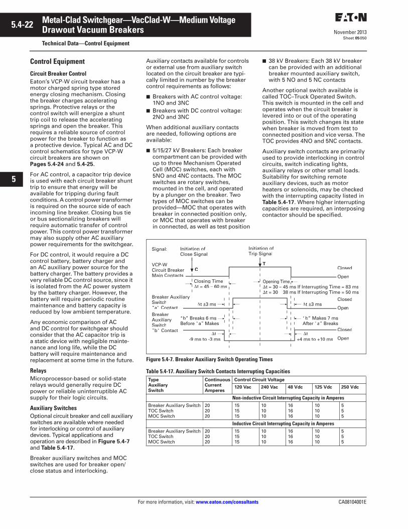
5.4-22
For more information, visit: www.eaton.com/consultants CA08104001E
November 2013
Metal-Clad Switchgear—VacClad-W—Medium Voltage
i
ii
1
2
3
4
5
6
7
8
9
10
11
12
13
14
15
16
17
18
19
20
21
Sheet 05
Drawout Vacuum BreakersTechnical Data—Control Equipment
050
Control Equipment
Circuit Breaker ControlEaton’s VCP-W circuit breaker has a motor charged spring type stored energy closing mechanism. Closing the breaker charges accelerating springs. Protective relays or the control switch will energize a shunt trip coil to release the accelerating springs and open the breaker. This requires a reliable source of control power for the breaker to function as a protective device. Typical AC and DC control schematics for type VCP-W circuit breakers are shown on Pages 5.4-24 and 5.4-25.
For AC control, a capacitor trip device is used with each circuit breaker shunt trip to ensure that energy will be available for tripping during fault conditions. A control power transformer is required on the source side of each incoming line breaker. Closing bus tie or bus sectionalizing breakers will require automatic transfer of control power. This control power transformer may also supply other AC auxiliary power requirements for the switchgear.
For DC control, it would require a DC control battery, battery charger and an AC auxiliary power source for the battery charger. The battery provides a very reliable DC control source, since it is isolated from the AC power system by the battery charger. However, the battery will require periodic routine maintenance and battery capacity is reduced by low ambient temperature.
Any economic comparison of AC and DC control for switchgear should consider that the AC capacitor trip is a static device with negligible mainte-nance and long life, while the DC battery will require maintenance and replacement at some time in the future.
RelaysMicroprocessor-based or solid-state relays would generally require DC power or reliable uninterruptible AC supply for their logic circuits.
Auxiliary SwitchesOptional circuit breaker and cell auxiliary switches are available where needed for interlocking or control of auxiliary devices. Typical applications and operation are described in Figure 5.4-7 and Table 5.4-17.
Breaker auxiliary switches and MOC switches are used for breaker open/close status and interlocking.
Auxiliary contacts available for controls or external use from auxiliary switch located on the circuit breaker are typi-cally limited in number by the breaker control requirements as follows:
■ Breakers with AC control voltage: 1NO and 3NC
■ Breakers with DC control voltage: 2NO and 3NC
When additional auxiliary contacts are needed, following options are available:
■ 5/15/27 kV Breakers: Each breaker compartment can be provided with up to three Mechanism Operated Cell (MOC) switches, each with 5NO and 4NC contacts. The MOC switches are rotary switches, mounted in the cell, and operated by a plunger on the breaker. Two types of MOC switches can be provided—MOC that operates with breaker in connected position only, or MOC that operates with breaker in connected, as well as test position
■ 38 kV Breakers: Each 38 kV breaker can be provided with an additional breaker mounted auxiliary switch, with 5 NO and 5 NC contacts
Another optional switch available is called TOC–Truck Operated Switch. This switch is mounted in the cell and operates when the circuit breaker is levered into or out of the operating position. This switch changes its state when breaker is moved from test to connected position and vice versa. The TOC provides 4NO and 5NC contacts.
Auxiliary switch contacts are primarily used to provide interlocking in control circuits, switch indicating lights, auxiliary relays or other small loads. Suitability for switching remote auxiliary devices, such as motor heaters or solenoids, may be checked with the interrupting capacity listed in Table 5.4-17. Where higher interrupting capacities are required, an interposing contactor should be specified.
Figure 5.4-7. Breaker Auxiliary Switch Operating Times
Table 5.4-17. Auxiliary Switch Contacts Interrupting Capacities Type Auxiliary Switch
ContinuousCurrentAmperes
Control Circuit Voltage
120 Vac 240 Vac 48 Vdc 125 Vdc 250 Vdc
Non-inductive Circuit Interrupting Capacity in AmperesBreaker Auxiliary SwitchTOC SwitchMOC Switch
202020
151515
101010
161616
101010
555
Inductive Circuit Interrupting Capacity in AmperesBreaker Auxiliary SwitchTOC SwitchMOC Switch
202020
151515
101010
161616
101010
555
Initiation ofClose Signal
Signal: Initiation ofTrip Signal
Closed
OpenOpening Time� – 45 ms If Interrupting Time = 83 ms� –
“b”“a”
�t-9 ms to -3 ms
�t ±3 ms
Closing Time�t = 45 – 60 ms
VCP-WCircuit BreakerMain Contacts
Breaker AuxiliarySwitch”a“ Contact
C
T
Closed
Openee
Closed
Open
Breaker
Switch”b“ Contact
�t+4 ms to +10 ms
“b”“a” Makes
�t ±3 ms
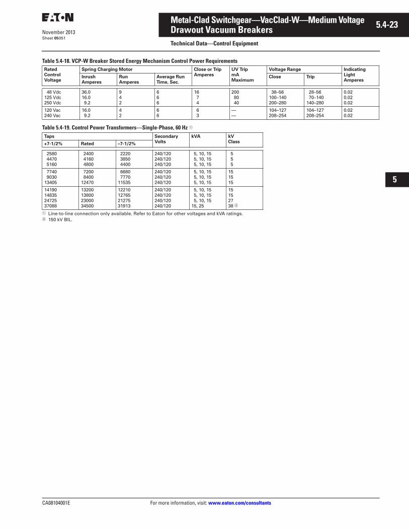
CA08104001E For more information, visit: www.eaton.com/consultants
5.4-23November 2013
Metal-Clad Switchgear—VacClad-W—Medium Voltage
i
ii
1
2
3
4
5
6
7
8
9
10
11
12
13
14
15
16
17
18
19
20
21
Sheet 05
Drawout Vacuum BreakersTechnical Data—Control Equipment
051
Table 5.4-18. VCP-W Breaker Stored Energy Mechanism Control Power Requirements
Table 5.4-19. Control Power Transformers—Single-Phase, 60 Hz �
� Line-to-line connection only available. Refer to Eaton for other voltages and kVA ratings.� 150 kV BIL.
RatedControlVoltage
Spring Charging Motor Close or TripAmperes
UV TripmA Maximum
Voltage Range IndicatingLightAmperes
InrushAmperes
RunAmperes
Average RunTime, Sec.
Close Trip
48 Vdc125 Vdc250 Vdc
36.016.0 9.2
942
666
16 7 4
200 80 40
38–56100–140200–280
28–56 70–140140–280
0.020.020.02
120 Vac240 Vac
16.0 9.2
42
66
6 3
——
104–127208–254
104–127208–254
0.020.02
Taps SecondaryVolts
kVA kVClass+7-1/2% Rated –7-1/2%
2580 4470 5160
2400 4160 4800
2220 3850 4400
240/120240/120240/120
5, 10, 15 5, 10, 15 5, 10, 15
5 5 5
7740 903013405
7200 840012470
6680 777011535
240/120240/120240/120
5, 10, 15 5, 10, 15 5, 10, 15
151515
14190148352472537088
13200138002300034500
12210127652127531913
240/120240/120240/120240/120
5, 10, 15 5, 10, 15 5, 10, 1515, 25
15152738 �
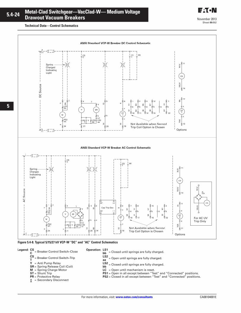
5.4-24
For more information, visit: www.eaton.com/consultants CA08104001E
November 2013
Metal-Clad Switchgear—VacClad-W— Medium Voltage
i
ii
1
2
3
4
5
6
7
8
9
10
11
12
13
14
15
16
17
18
19
20
21
Sheet 05
Drawout Vacuum BreakersTechnical Data—Control Schematics
052
Figure 5.4-8. Typical 5/15/27 kV VCP-W “DC” and “AC” Control Schematics
Operation: LS1bbLS2aaLS2bbLC = Open until mechanism is reset.PS1 = Open in all except between “Test” and “Connected” positions.PS2 = Closed in all except between “Test” and “Connected” positions.
Legend: CSC CSTY = Anti Pump RelaySR = Spring Release Coil (Coil)M = Spring Charge MotorST = Shunt TripPR = Protective Relay = Secondary Disconnect>>
= Breaker Control Switch–Close
= Breaker Control Switch–Trip
= Closed until springs are fully charged.
= Open until springs are fully charged.
= Closed until springs are fully charged.
DC
So
urc
e
N(-)
P(+)
1 2
24
LS1
34
M
bb
PS2bb
4
YLC
Y
6
Y
7
bb aa
b
SR
513
14
b
GL
19
6
910
1
a
a
TION
7
18
8
17
9
16
10
15
5152
5354
5556
5758
3
22
6162
CSC
RL
CST
_51NONIONTIOATIONATIONATIONTATATAT_S_S_S_TRCSRCS_TATATATATATATATATATATATATATTCSSTCSSLTTCSSLTTCSSLT
PR
WL
13
12
9A10
A
2
a
a
51NONTIONTIOTIOTIOTIOCS_TRCSCS_TCSSLTTT TCATIOCATIOCATCATIOCATIOCATLOCATLOCATIOLOCATLOCATLOCATIOLOCATLOCAT
11
9UV
UV
ST
Options
Not Available when SecondTrip Coil Option is Chosen
ANSI Standard VCP-W Breaker DC Control Schematic
ST
AC
So
urc
e
1 2
LS1
34
M
bb
PS2bb
4
Y
Y
6
Y
7
bb aa1
SR
5
1314
b
GL
16
9
5556
a
RL
6
10
1
a
a
AC
AC (–)
CSC
TPR
WL
(+)
2
1
7
18
8
17
10
15
5152
5354
5758
3
22
6162
13
12
9A
2
a
a
TIONO_51NONTIONTIOTIOTIOTIOTTIOTIOTIO_CS_TRCS_TRCS_TCSSLTTT TCATIOCATCATCATIOCATCATLOCATLOCATIOLOCATLOCATLOCATIOLOCATLOCAT
14
11
9UV
10U
VUV
TIONO 51NONTIONTIOTIOTIOTIOCS_TRCSCS_TCSSTTT ATCATIOCATIOCATCATIOCATIOCATLOCATLOCATIOLOCATLOCATLOCATIOLOCATLOCAT
ST
Options
Not Available when SecondTrip Coil Option is Chosen
ST
UV
9UV
10U
V
For AC UVTrip Only
ANSI Standard VCP-W Breaker AC Control Schematic
SpringChargedIndicatingLight
SpringChargedIndicatingLight
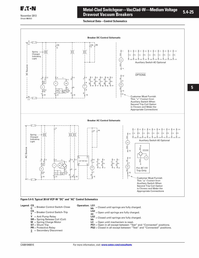
CA08104001E For more information, visit: www.eaton.com/consultants
5.4-25November 2013
Metal-Clad Switchgear—VacClad-W—Medium Voltage
i
ii
1
2
3
4
5
6
7
8
9
10
11
12
13
14
15
16
17
18
19
20
21
Sheet 05
Drawout Vacuum BreakersTechnical Data—Control Schematics
053
Figure 5.4-9. Typical 38 kV VCP-W “DC” and “AC” Control Schematics
N(-)
P(+)
24
3
3A
4
M
PS2bb
4
21
LS2YLC
Y
6
Y
7
aa
b
SR
20
5
1314
b
19
6
910
a
TION
7
18
8
17
9
53 5556
5758
3
22
6162
TIONLOCAT
CSC
CST
51NONTIONTIOATIOATIOATIOS_TRCSRCS_TCSSLTCTCTC TATATATATATATLOCATLOCATLOCATLOCATLOCATLOCATLOCAT
PR
13
12
9A10
A
2
a
14
11
9UV
10U
V
UV
51NONONTIOATIONATIONATIONS_TRCSTRCS_TCSSLTCTCTC TATIATIATIATIATIATILOCATLOCATILOCATILOCATILOCATILOCATILOCATI
ST
SpringChargedIndicatingLight
ST
U1
U24
U2
U23
U3
U22
U4
U21U24
U5
U20
U6
U19
U7
U18
U8 U9 U10
U15
This ”a Contact from
Second Trip Coil Optionis Chosen and Make theAppropriate Connections
Breaker DC Control Schematic
1 2
24
LS1
3
3A
4
M
PS2bb
4
PS Y
6
Y SR
20
5
1314
b
16
9
5556
a
19
6
9
1
a
a
AC
AC (-)
CAP TRIP DEV
CSC
PR
(+)
2
1
7
18
8
17
10
15
5152
53 57
3
22TIONLOCAT
9UV
10U
V
UV
TIONO_51NONONTIOATIOTATIO_TRCS_TRCSTCSSATATIOLOCATLOCATIOLOCALOCALOCALOCALOCA
ST
UV
9UV
10U
V
For AC UVTrip Only
Breaker AC Control Schematic
12
9A
2
a
a
ST
This ” “ Contact from
Second Trip Coil Optionis Chosen and Make theAppropriate Connections
U1 U2 U3
U22
U4
U21U24
U5
U20
U6
U19
U7
U18
U8
U17
U9
U16
U10
U15
OPTIONS
OPTIONS
DC
So
urc
e
GL RLWL
GL RLWLSpringChargedIndicatingLight
AC
So
urc
e
Operation: LS1bbLS2aaLS2bbLC = Open until mechanism is reset.PS1 = Open in all except between “Test” and “Connected” positions.PS2 = Closed in all except between “Test” and “Connected” positions.
Legend: CSC CSTY = Anti Pump RelaySR = Spring Release Coil (Coil)M = Spring Charge MotorST = Shunt TripPR = Protective Relay = Secondary Disconnect>>
= Breaker Control Switch–Close
= Breaker Control Switch–Trip
= Closed until springs are fully charged.
= Open until springs are fully charged.
= Closed until springs are fully charged.
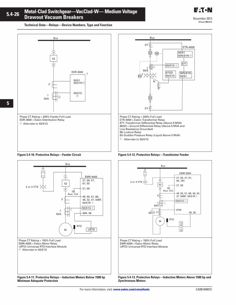
5.4-26
For more information, visit: www.eaton.com/consultants CA08104001E
November 2013
Metal-Clad Switchgear—VacClad-W— Medium Voltage
i
ii
1
2
3
4
5
6
7
8
9
10
11
12
13
14
15
16
17
18
19
20
21
Sheet 05
Drawout Vacuum BreakersTechnical Data—Relays—Device Numbers, Type and Function
054
Figure 5.4-10. Protective Relays—Feeder Circuit
Figure 5.4-11. Protective Relays—Induction Motors Below 1500 hp Minimum Adequate Protection
Figure 5.4-12. Protective Relays—Transformer Feeder
Figure 5.4-13. Protective Relays—Induction Motors Above 1500 hp and Synchronous Motors
Phase CT Rating = 200% Feeder Full LoadEDR-3000 = Eaton Distribution Relay� Alternate to 50/51G
Bus
50/5
1
1
3
52
50/5150/51N
50/51G
EDR-3000
�
Bus
50/51
3
52
49R, 38
49, 50, 51, 66, 46, 32, 37, 50BF,50/51R
EMR-4000
M
2 or 3 VTS27, 59
27, 59, 47,81, 55
1ØAux. Vol.
URTDRTD
50/51G
Phase CT Rating = 150% Full LoadEMR-4000 = Eaton Motor RelayURTD–Universal RTD Interface Module� Alternate to 50/51G
Bus
50/51
1
N
ETR-4000
50/5150N/51N
50N/51N50/51
87T50/51G
87GD50/51G
3Y
3Y
52
52
86
63
�
Phase CT Rating = 200% Full LoadETR-4000 = Eaton Transformer Relay87T–Transformer Differential Relay (Above 5 MVA)86GD = Ground Differential Relay (Above 5 MVA and Low Resistance Grounded)86–Lockout Relay63–Sudden Pressure Relay (Liquid Above 5 MVA)� Alternate to 50/51G
URTD
52
M
Bus
RTD
3
3NEUT
50/51
2 or 3 VTS
87M
49, 50, 51, 66, 46, 32, 37, 50BF, 50/51R
EMR-5000
27, 59
27, 59, 47, 81, 55, 78V
1ØAux. Vol.
50/51G
49, 38
Phase CT Rating = 150% Full LoadEMR-5000 = Eaton Motor RelayURTD–Universal RTD Interface Module
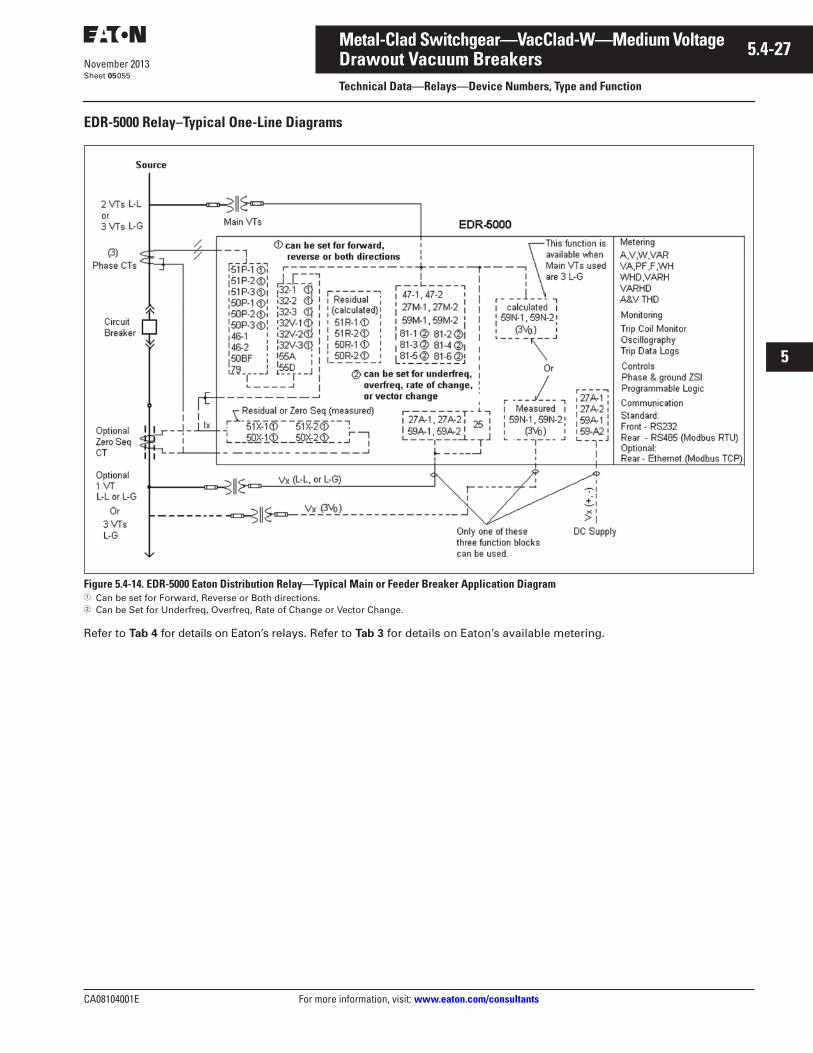
CA08104001E For more information, visit: www.eaton.com/consultants
5.4-27November 2013
Metal-Clad Switchgear—VacClad-W—Medium Voltage
i
ii
1
2
3
4
5
6
7
8
9
10
11
12
13
14
15
16
17
18
19
20
21
Sheet 05
Drawout Vacuum BreakersTechnical Data—Relays—Device Numbers, Type and Function
055
EDR-5000 Relay–Typical One-Line Diagrams
Figure 5.4-14. EDR-5000 Eaton Distribution Relay—Typical Main or Feeder Breaker Application Diagram� Can be set for Forward, Reverse or Both directions.� Can be Set for Underfreq, Overfreq, Rate of Change or Vector Change.
Refer to Tab 4 for details on Eaton’s relays. Refer to Tab 3 for details on Eaton’s available metering.
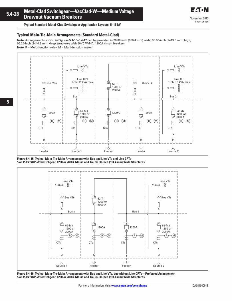
5.4-28
For more information, visit: www.eaton.com/consultants CA08104001E
November 2013
Metal-Clad Switchgear—VacClad-W—Medium Voltage
i
ii
1
2
3
4
5
6
7
8
9
10
11
12
13
14
15
16
17
18
19
20
21
Sheet 05
Drawout Vacuum BreakersTypical Standard Metal-Clad Switchgear Application Layouts, 5–15 kV
056
Typical Main-Tie-Main Arrangements (Standard Metal-Clad)Note: Arrangements shown in Figures 5.4-15–5.4-17 can be provided in 26.00-inch (660.4 mm) wide, 95.00-inch (2413.0 mm) high, 96.25-inch (2444.8 mm) deep structures with 50VCPWND, 1200A circuit breakers.Note: R = Multi-function relay, M = Multi-function meter.
Figure 5.4-15. Typical Main-Tie-Main Arrangement with Bus and Line VTs and Line CPTs5 or 15 kV VCP-W Switchgear, 1200 or 2000A Mains and Tie, 36.00-Inch (914.4 mm) Wide Structures
Figure 5.4-16. Typical Main-Tie-Main Arrangement with Bus and Line VTs, but without Line CPTs—Preferred Arrangement5 or 15 kV VCP-W Switchgear, 1200 or 2000A Mains and Tie, 36.00-Inch (914.4 mm) Wide Structures
Line VTs
Bus 2
CTs
R M
Source 2Feeder
52-M21200 or2000A
CTs
R M
1200A
Feeder
CTs
R M
1200A
Bus VTsBus VTs
Feeder
CTs
R M
1200A
52-T1200 or2000A
Line CPT1-ph, 15 kVA max.
Line VTs
Bus 1
CTs
R M
Source 1
52-M11200 or 2000A
Line CPT1-ph, 15 kVA max.
Line VTs
Bus 2
CTs
Source 2Feeder
52-M21200 or2000A
CTs
R M
1200A
Bus VTsBus VTs
Feeder
CTs
R M
1200A
52-T1200 or2000 A
Line VTs
Bus 1
CTs
R M
Source 1
52-M11200 or2000A
R M
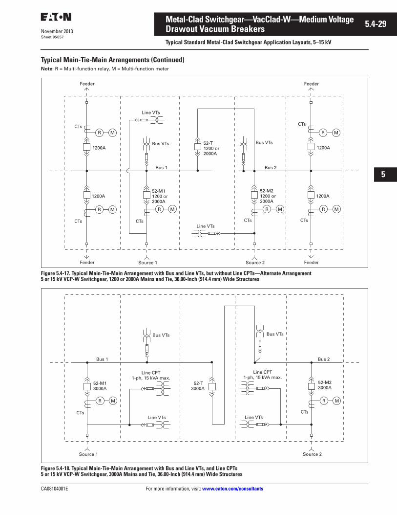
CA08104001E For more information, visit: www.eaton.com/consultants
5.4-29November 2013
Metal-Clad Switchgear—VacClad-W—Medium Voltage
i
ii
1
2
3
4
5
6
7
8
9
10
11
12
13
14
15
16
17
18
19
20
21
Sheet 05
Drawout Vacuum BreakersTypical Standard Metal-Clad Switchgear Application Layouts, 5–15 kV
057
Typical Main-Tie-Main Arrangements (Continued)Note: R = Multi-function relay, M = Multi-function meter
Figure 5.4-17. Typical Main-Tie-Main Arrangement with Bus and Line VTs, but without Line CPTs—Alternate Arrangement5 or 15 kV VCP-W Switchgear, 1200 or 2000A Mains and Tie, 36.00-Inch (914.4 mm) Wide Structures
Figure 5.4-18. Typical Main-Tie-Main Arrangement with Bus and Line VTs, and Line CPTs 5 or 15 kV VCP-W Switchgear, 3000A Mains and Tie, 36.00-Inch (914.4 mm) Wide Structures
MR MR
MRMR
Feeder
CTs
1200A
1200A
CTs
Feeder
CTs
52-M21200 or2000A
52-T1200 or2000A
CTsCTs
CTs
Feeder
Feeder
52-M11200 or2000A
1200A
1200A
Source 1 Source 2
Line VTs
Line VTs
Bus VTsBus VTs
Bus 2Bus 1
MR MR
CTs
52-M23000A
52-T3000A
Source 2
Bus VTsBus VTs
Bus 2Bus 1
MR
CTs
52-M13000A
Source 1
MR
Line VTsLine VTs
Line CPT1-ph, 15 kVA max.
Line CPT1-ph, 15 kVA max.
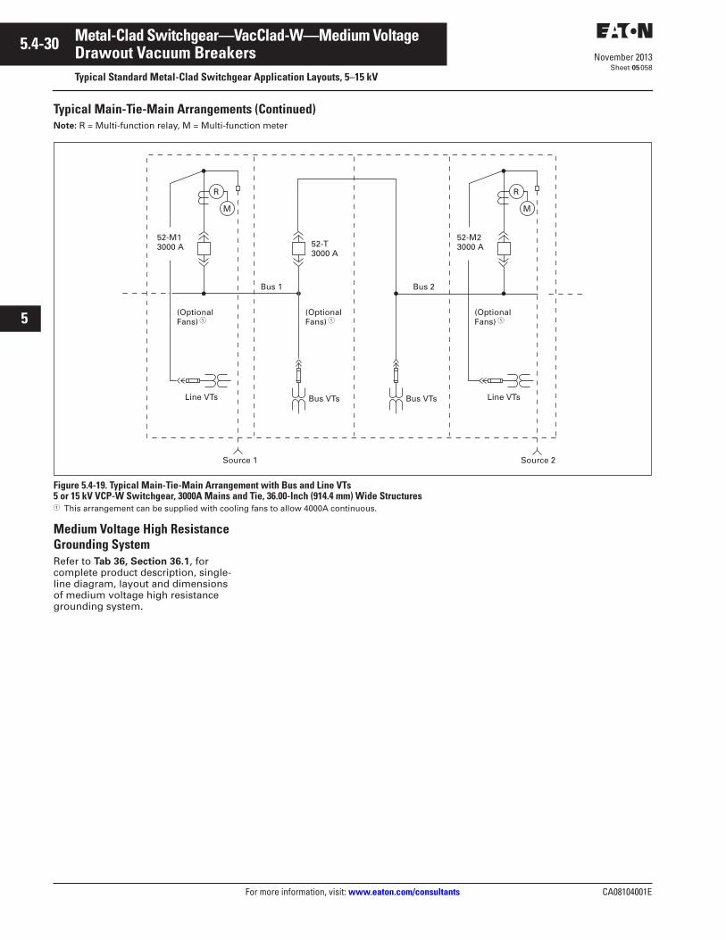
5.4-30
For more information, visit: www.eaton.com/consultants CA08104001E
November 2013
Metal-Clad Switchgear—VacClad-W—Medium Voltage
i
ii
1
2
3
4
5
6
7
8
9
10
11
12
13
14
15
16
17
18
19
20
21
Sheet 05
Drawout Vacuum BreakersTypical Standard Metal-Clad Switchgear Application Layouts, 5–15 kV
058
Typical Main-Tie-Main Arrangements (Continued)Note: R = Multi-function relay, M = Multi-function meter
Figure 5.4-19. Typical Main-Tie-Main Arrangement with Bus and Line VTs 5 or 15 kV VCP-W Switchgear, 3000A Mains and Tie, 36.00-Inch (914.4 mm) Wide Structures� This arrangement can be supplied with cooling fans to allow 4000A continuous.
Medium Voltage High Resistance Grounding SystemRefer to Tab 36, Section 36.1, for complete product description, single-line diagram, layout and dimensions of medium voltage high resistance grounding system.
M
R
52-M13000 A 52-T
3000 A
Bus VTs
Bus 2Bus 1
M
R
52-M23000 A
Bus VTs
(OptionalFans)
(OptionalFans)
(OptionalFans)
Line VTs Line VTs
Source 1 Source 2
� ��
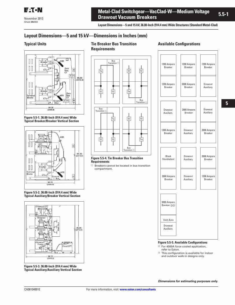
CA08104001E For more information, visit: www.eaton.com/consultants
5.5-1November 2013
Metal-Clad Switchgear—VacClad-W—Medium Voltage
i
ii
1
2
3
4
5
6
7
8
9
10
11
12
13
14
15
16
17
18
19
20
21
Sheet 05
Drawout Vacuum BreakersLayout Dimensions—5 and 15 kV, 36.00-Inch (914.4 mm) Wide Structures (Standard Metal-Clad)
059
Layout Dimensions—5 and 15 kV—Dimensions in Inches (mm)
Typical Units
Figure 5.5-1. 36.00-Inch (914.4 mm) Wide Typical Breaker/Breaker Vertical Section
Figure 5.5-2. 36.00-Inch (914.4 mm) Wide Typical Auxiliary/Breaker Vertical Section
Figure 5.5-3. 36.00-Inch (914.4 mm) Wide Typical Auxiliary/Auxiliary Vertical Section
Tie Breaker Bus Transition Requirements
Figure 5.5-4. Tie Breaker Bus Transition Requirements� Breakers cannot be located in bus transition
compartment.
Available Configurations
Figure 5.5-5. Available Configurations� For 4000A force cooled application,
refer to Eaton.� This configuration is available for indoor
and outdoor walk-in designs only.
�
�
�
�
Dimensions for estimating purposes only.
1200 AmpereBreaker
DrawoutAuxiliary
Blank(Ventilation)
Vent Area
1200 AmpereBreaker
1200 AmpereBreaker
1200 AmpereBreaker
2000 AmpereBreaker
DrawoutAuxiliary
DrawoutAuxiliary
2000 AmpereBreaker
DrawoutAuxiliary
1200 AmpereBreaker
2000 AmpereBreaker
DrawoutAuxiliary
2000 AmpereBreaker
DrawoutAuxiliary
1200 AmpereBreaker
3000 AmpereBreaker
3000 AmpereBreaker
DrawoutAuxiliary
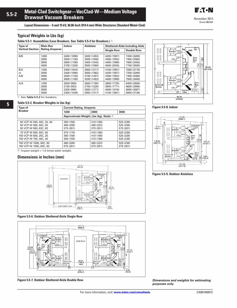
5.5-2
For more information, visit: www.eaton.com/consultants CA08104001E
November 2013
Metal-Clad Switchgear—VacClad-W—Medium Voltage
i
ii
1
2
3
4
5
6
7
8
9
10
11
12
13
14
15
16
17
18
19
20
21
Sheet 05
Drawout Vacuum BreakersLayout Dimensions—5 and 15 kV, 36.00-Inch (914.4 mm) Wide Structures (Standard Metal-Clad)
060
Typical Weights in Lbs (kg)Table 5.5-1. Assemblies (Less Breakers. See Table 5.5-2 for Breakers.) �
� See Table 5.5-2 for breakers.
Table 5.5-2. Breaker Weights in Lbs (kg)
� Impact weight = 1.5 times static weight.
Dimensions in Inches (mm)
Figure 5.5-6. Outdoor Sheltered Aisle Single Row
Figure 5.5-7. Outdoor Sheltered Aisle Double Row
Type ofVertical Section
Main BusRating Amperes
Indoor Aisleless Sheltered-Aisle Including Aisle
Single Row Double Row
B/B 1200200030004000
2400 (1090)2500 (1135)2600 (1180)2700 (1226)
3200 (1453)3300 (1500)3400 (1545)3500 (1590)
4200 (1907)4300 (1952)4400 (1998)4500 (2045)
7200 (3269)7400 (3360)7600 (3450)7700 (3500)
B/AorA/B
1200200030004000
2300 (1044)2400 (1090)2500 (1135)2600 (1180)
2900 (1317)3000 (1362)3100 (1407)3200 (1453)
4100 (1861)4200 (1907)4300 (1952)4400 (1998)
7000 (3178)7200 (3269)7400 (3360)7500 (3409)
A/A 1200200030004000
2000 (908)2100 (953)2200 (999)2300 (1046)
2600 (1180)2700 (1226)2800 (1271)2900 (1317)
3800 (1725)3900 (1771)4000 (1816)4100 (1861)
6400 (2906)6600 (2996)6800 (3087)6900 (3136)
Type of Breaker
Current Rating, Amperes
1200 2000 3000
Approximate Weight, Lbs (kg), Static �
50 VCP-W 250, 40C, 25, 40 50 VCP-W 350, 50C, 50 50 VCP-W 500, 63C, 63
350 (159)460 (209)575 (261)
410 (186)490 (222)575 (261)
525 (238)525 (238)575 (261)
75 VCP-W 500, 50C, 50150 VCP-W 500, 25C, 25150 VCP-W 750, 40C, 40
375 (170)350 (159)350 (159)
410 (186)410 (186)410 (186)
525 (238)525 (238)525 (238)
150 VCP-W 1000, 50C, 50150 VCP-W 1500, 63C, 63
460 (209)575 (261)
490 (222)575 (261)
525 (238)575 (261)
Figure 5.5-8. Indoor
Figure 5.5-9. Outdoor Aisleless
Dimensions and weights for estimating purposes only.
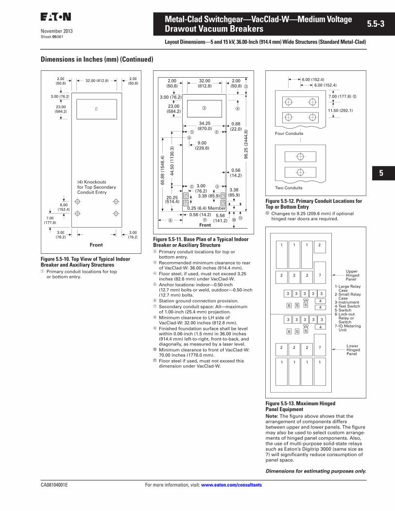
CA08104001E For more information, visit: www.eaton.com/consultants
5.5-3November 2013
Metal-Clad Switchgear—VacClad-W—Medium Voltage
i
ii
1
2
3
4
5
6
7
8
9
10
11
12
13
14
15
16
17
18
19
20
21
Sheet 05
Drawout Vacuum BreakersLayout Dimensions—5 and 15 kV, 36.00-Inch (914.4 mm) Wide Structures (Standard Metal-Clad)
061
Dimensions in Inches (mm) (Continued)
Figure 5.5-10. Top View of Typical Indoor Breaker and Auxiliary Structures� Primary conduit locations for top
or bottom entry.
Figure 5.5-11. Base Plan of a Typical Indoor Breaker or Auxiliary Structure� Primary conduit locations for top or
bottom entry.� Recommended minimum clearance to rear
of VacClad-W: 36.00 inches (914.4 mm).� Floor steel, if used, must not exceed 3.25
inches (82.6 mm) under VacClad-W.� Anchor locations: indoor—0.50-inch
(12.7 mm) bolts or weld, outdoor—0.50-inch (12.7 mm) bolts.
� Station ground connection provision.� Secondary conduit space: All—maximum
of 1.00-inch (25.4 mm) projection.� Minimum clearance to LH side of
VacClad-W: 32.00 inches (812.8 mm). Finished foundation surface shall be level
within 0.06-inch (1.5 mm) in 36.00 inches (914.4 mm) left-to-right, front-to-back, and diagonally, as measured by a laser level.
� Minimum clearance to front of VacClad-W: 70.00 inches (1778.0 mm).
� Floor steel if used, must not exceed this dimension under VacClad-W.
Figure 5.5-12. Primary Conduit Locations for Top or Bottom Entry� Changes to 8.25 (209.6 mm) if optional
hinged rear doors are required.
Figure 5.5-13. Maximum Hinged Panel EquipmentNote: The figure above shows that the arrangement of components differs between upper and lower panels. The figure may also be used to select custom arrange-ments of hinged panel components. Also, the use of multi-purpose solid-state relays such as Eaton’s Digitrip 3000 (same size as 7) will significantly reduce consumption of panel space.
3.00(76.2)
23.00(584.2)
3.00 (76.2)
2.00(50.8)
➀
6.00(152.4)
(4) Knockoutsfor Top SecondarTT yConduit Entry
2.00(50.8)
3.00(76.2)
Front
7.00(177.8)
32.00 (812.8)
3.38 (85.9)3.38
(85.9)
5.56(141.2)
0.56(14.2)
3.00(76.2)
23.00(584.2)
32.00(812.8)
3.00 (76.2)
20.25(514.4)
0.25 (6.4) Member
96.2
5 (2
444.
8)
9.00(228.6)
2.00(50.8)
34.25(870.0)
60.8
8 (1
546.
4)
44.5
0 (1
130.
3)
0.56 (14.2)
2.00(50.8)
�
�
Front
�
�
��
�
�
��
�
�
�
�
0.88(22.0)
Dimensions for estimating purposes only.
11.50 (292.1)
Two Conduits
Four Conduits
7.00 (177.8)
6.00 (152.4)6.00 (152.4)
1 1 1 2
1 1 1 1
2 2 2 7
2 2 2 7
4
4
4
3 3 3 3 3
3 3 3 3 3
6 5 5
6 5 5
UpperHingedPanel
LowerHingedPanel
1-Large RelayCase
2-Small RelayCase
3-Instrument4-Test Switch5-Switch6-Lock-out
Relay orSwitch
7-IQ MeteringUnit
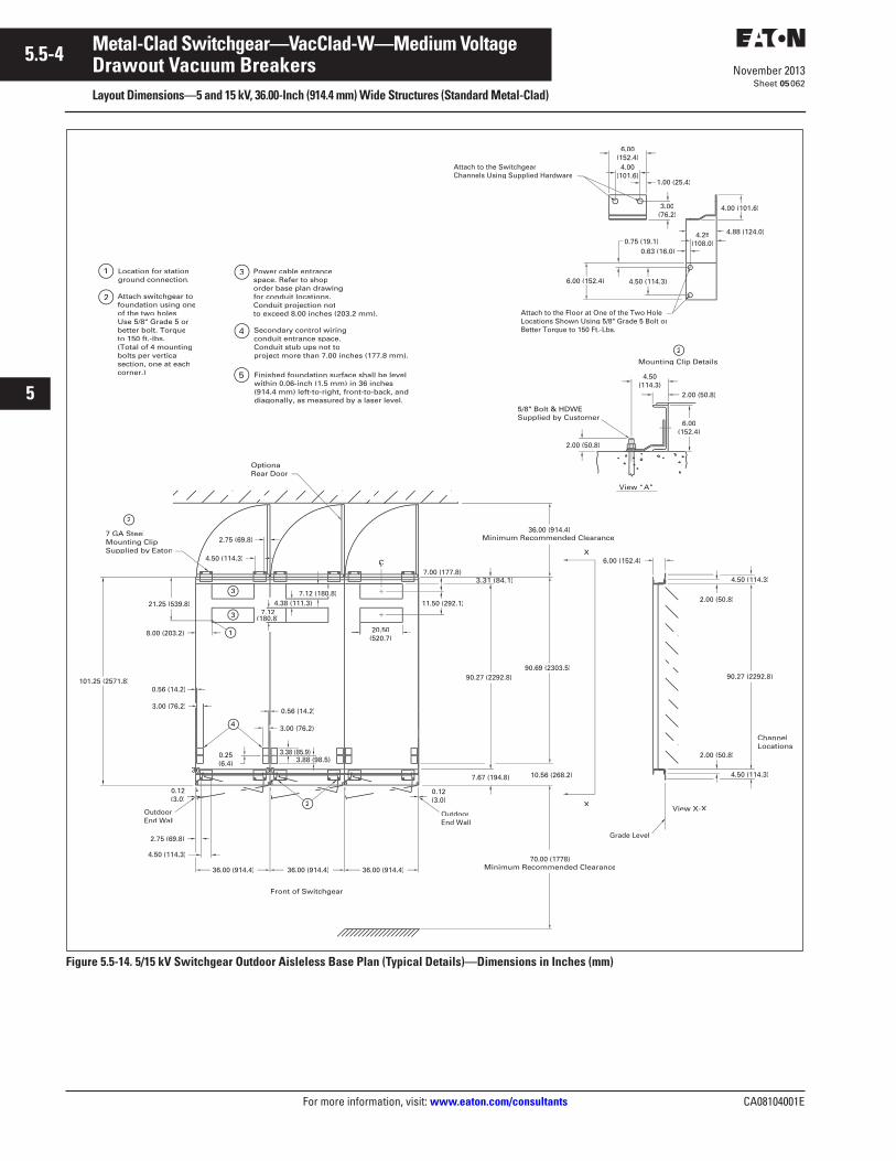
5.5-4
For more information, visit: www.eaton.com/consultants CA08104001E
November 2013
Metal-Clad Switchgear—VacClad-W—Medium Voltage
i
ii
1
2
3
4
5
6
7
8
9
10
11
12
13
14
15
16
17
18
19
20
21
Sheet 05
Drawout Vacuum BreakersLayout Dimensions—5 and 15 kV, 36.00-Inch (914.4 mm) Wide Structures (Standard Metal-Clad)
062
Figure 5.5-14. 5/15 kV Switchgear Outdoor Aisleless Base Plan (Typical Details)—Dimensions in Inches (mm)
Location for stationground connection.
1
2 Attach switchgear tofoundation using oneof the two holes.Use 5/8" Grade 5 orbetter bolt. Torqueto 150 ft.-lbs.(Total of 4 mountingbolts per verticalsection, one at eachcorner.)
Power cable entrancespace. Refer to shoporder base plan drawingfor conduit locations.Conduit projection notto exceed 8.00 inches (203.2 mm).
3
Secondary control wiringconduit entrance space.Conduit stub ups not toproject more than 7.00 inches (177.8 mm).
4
4.50 (114.3)
View X-X
70.00 (1778)Minimum Recommended Clearance
Front of Switchgear
6.00 (152.4)
0.12(3.0)
36.00 (914.4)
0.25(6.4)
0.56 (14.2)
7.12(180.8)
8.00 (203.2) 20.50(520.7)
21.25 (539.8)
(3.0)
90.69 (2303.5)
36.00 (914.4)Minimum Recommended Clearance
4.38 (111.3)
ChannelLocations
4
OutdoorEnd Wall
OutdoorEnd Wall
OptionalRear Door
1
2
7 GA SteelMounting ClipSupplied by Eaton
3.00 (76.2)0.56 (14.2)
101.25 (2571.8)
36.00 (914.4) 36.00 (914.4)
4.50 (114.3)
90.27 (2292.8)
X
X
3
3
2
10.56 (268.2)
2.00 (50.8)
7.67 (194.8)
2.00 (50.8)
Grade Level
11.50 (292.1)
3.31 (84.1)
90.27 (2292.8)
7.12 (180.8)
CLCC
Attach to the SwitchgearChannels Using Supplied Hardware
6.00(152.4)
1.00 (25.4)(101.6)
2.00 (50.8)
5/8" Bolt & HDWESupplied by Customer
Attach to the Floor at One of the Two HoleLocations Shown Using 5/8" Grade 5 Bolt orBetter Torque to 150 Ft.-Lbs.
View “A”
2.00 (50.8)
6.00(152.4)
2
Mounting Clip Details
4.50
0.63 (16.0)
6.00 (152.4)
3.00(76.2)
4.25(108.0)
4.00 (101.6)
4.88 (124.0)
4.50 (114.3)
0.75 (19.1)
4.50 (114.3)
2.75 (69.8)
4.50 (114.3)
2.75 (69.8)
Finished foundation surface shall be levelwithin 0.06-inch (1.5 mm) in 36 inches(914.4 mm) left-to-right, front-to-back, anddiagonally, as measured by a laser level.
5
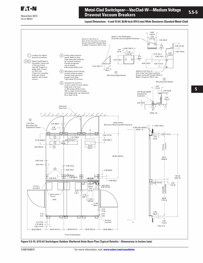
CA08104001E For more information, visit: www.eaton.com/consultants
5.5-5November 2013
Metal-Clad Switchgear—VacClad-W—Medium Voltage
i
ii
1
2
3
4
5
6
7
8
9
10
11
12
13
14
15
16
17
18
19
20
21
Sheet 05
Drawout Vacuum BreakersLayout Dimensions—5 and 15 kV, 36.00-Inch (914.4 mm) Wide Structures (Standard Metal-Clad)
063
Figure 5.5-15. 5/15 kV Switchgear Outdoor Sheltered Aisle Base Plan (Typical Details)—Dimensions in Inches (mm)
Ch
ann
el
Loca
tio
ns
Aisle
LOC
AT
ION
SC
HA
NN
EL
38.00 (965.2) 36.00 (914.4)
OutdoorEnd Wall
OutdoorEnd Wall
38.00 (965.2)
90.69 (2303.5)
5.75 (146.1)
5.75 (146.1)
6.00 (152.4)
90.27(2292.8)
68.96(1751.6)
4.00(101.6)
0.10(2.5)
0.10(2.5)
0.75(19.1)
11.50(292.1)
0.70(17.8)
3.88 (98.5)
3.38 (85.9)
11.40(289.6)
11.50(292.1)
167.23(4247.6)
4.88 (124.0)
Attach to the SwitchgearChannels Using Supplied Hardware
Attach to the Floor atOne of the Two Hole LocationsShown Using 5/8" Grade 5 Bolt orBetter Torque to 150 Ft.-Lbs.
Mounting Clip Details
36.00 (914.4) 36.00 (914.4)
Location for stationground connection.
1
5 Attach switchgear tofoundation using oneof the two holes.Use 5/8" Grade 5 orbetter bolt. Torqueto 150 ft.-lbs.(Total of 4 mountingbolts per verticalsection, one at eachcorner.)
Power cable entrancespace. Refer to shop
for conduit locations.Conduit projection not to exceed 8.00 inches (203.2 mm).
3
Secondary control wiringconduit entrance space.Conduit stub ups not toproject more than7.00 inches (177.8 mm).
4
Front of Switchgear
OptionalRear Door
2
36.00 (914.0)Minimum Recommended Clearance
3
3
1
2
7 GA SteelMounting ClipSupplied by Eaton
LCLL
7.00 (177.8)
11.50 (292.1)
20.50(520.7)
21.25 (539.8)
8.00 (203.2)
4.38 (111.3)7.12
(180.8)
7.12 (180.8)
0.56 (14.2)
3.00 (76.2)
4 3.00 (76.2)
0.56 (14.2)
0.12 (3.0)
0(50.8)
4.50(114.3)
4.50 (114.3)
RemovableCovers
4.00 (101.6)3.00 (76.2)
5
Mounting Angle Details
2
Typical
View X-X
X
2.75(69.8)
3.75(95.3)
6.50 (165.1)1.25
(31.8)
0.63 (16.0)
6.00(152.4)
(101.6)1.00 (25.4)
3.00(76.2)
6.00(152.4)
View “ ”
5/8" Bolt & HDWESupplied byCustomer
X SEE ENLARGEDVIEW “A”
2.00 (50.8)
2.00 (50.8)
4.50(114.3)
Attach to the Floor atOne of the Two Hole LocationsShown Using 5/8" Grade 5 Boltor Better Torque to 150 Ft.-Lbs.
4.25
6.00 (152.4) 4.50 (114.3)
0.75 (19.1)
4.50(114.3)
2.75 (69.8)
4.50 (114.3)2.75 (69.8)
Finished foundationsurface shall be level within0.06-inch (1.5 mm)in 36 inches (914.4 mm)left-to-right, front-to-back,and diagonally, as measuredby a laser level.
5
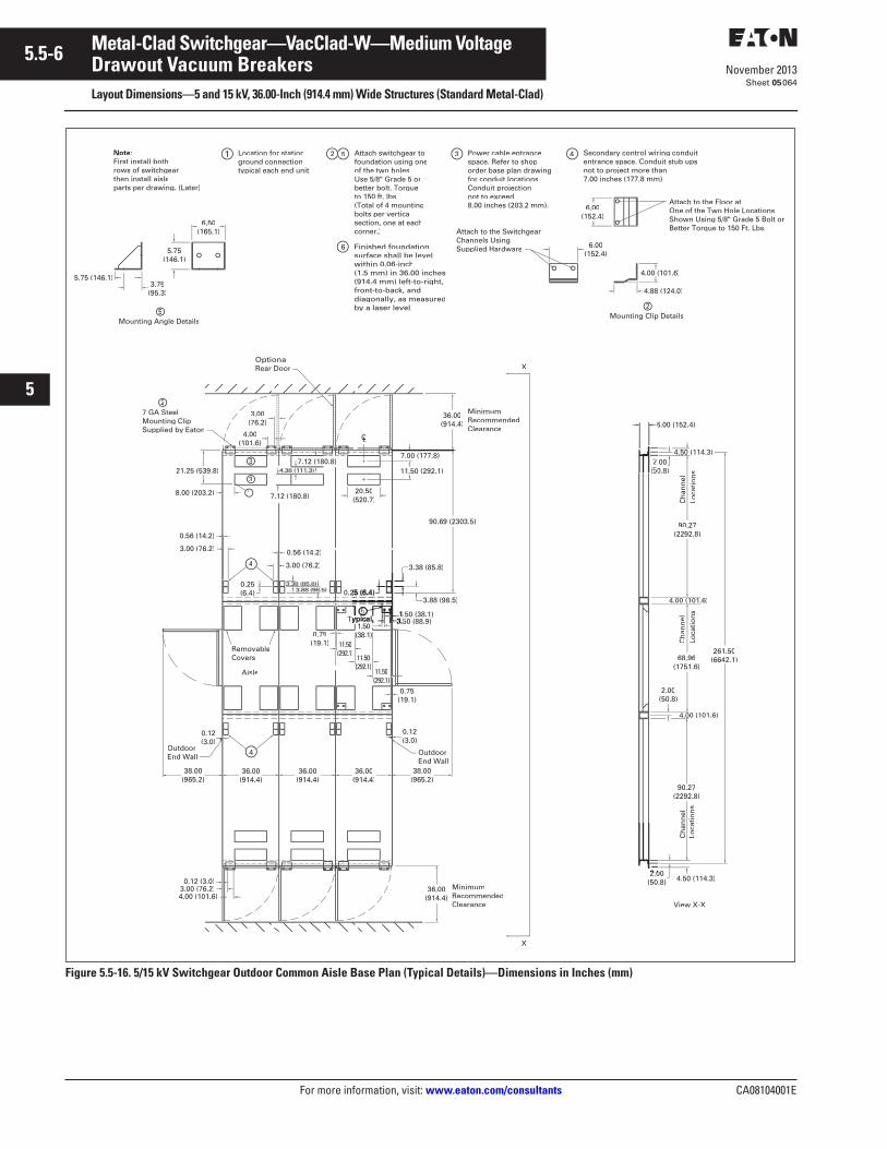
5.5-6
For more information, visit: www.eaton.com/consultants CA08104001E
November 2013
Metal-Clad Switchgear—VacClad-W—Medium Voltage
i
ii
1
2
3
4
5
6
7
8
9
10
11
12
13
14
15
16
17
18
19
20
21
Sheet 05
Drawout Vacuum BreakersLayout Dimensions—5 and 15 kV, 36.00-Inch (914.4 mm) Wide Structures (Standard Metal-Clad)
064
Figure 5.5-16. 5/15 kV Switchgear Outdoor Common Aisle Base Plan (Typical Details)—Dimensions in Inches (mm)
4.50 (114.3)
261.50(6642.1)
3.00 (76.2)
RemovableCovers
Ch
ann
elLo
cati
on
s
90.27(2292.8)
4.00 (101.6)
4.50 (114.3)00
(50.8)
Ch
ann
elLo
cati
on
sLo
cati
on
sC
han
nel
2.00(50.8)
Location for stationground connectiontypical each end unit.
1 5 Attach switchgear tofoundation using oneof the two holes.Use 5/8" Grade 5 orbetter bolt. Torqueto 150 ft. lbs.(Total of 4 mountingbolts per verticalsection, one at eachcorner.)
Power cable entrancespace. Refer to shoporder base plan drawingfor conduit locations.Conduit projection not to exceed 8.00 inches (203.2 mm).
3 Secondary control wiring conduit entrance space. Conduit stub ups not to project more than 7.00 inches (177.8 mm).
42
11.50 (292.1)
LL
3
3
1
27 GA SteelMounting ClipSupplied by Eaton
52
4
4
OutdoorEnd Wall
OutdoorEnd Wall
Aisle
3.75(95.3)
MinimumRecommendedClearance
Minimum RecommendedClearance
X
X
View X-X
Mounting Angle DetailsMounting Clip Details
Attach to the Floor atOne of the Two Hole LocationsShown Using 5/8" Grade 5 Bolt orBetter Torque to 150 Ft. Lbs.Attach to the Switchgear
Channels Using Supplied Hardware
36.00(914.4)
OptionalRear Door
Note:First install bothrows of switchgearthen install aisleparts per drawing. (Later)
11.50(292.1)
4.00 (101.6)
0.12 (3.0)
0.75(19.1)
11.50
3.00 (76.2)
0.56 (14.2)
0.56 (14.2)
3.00 (76.2)
90.27(2292.8)
68.96(1751.6)
4.00 (101.6)
6.00 (152.4)
3.88 (98.5)
3.38 (85.8)
90.69 (2303.5)
36.00(914.4)
20.50(520.7)
7.12 (180.8)
7.12 (180.8)
4.00
3.00(76.2)
21.25 (539.8)
8.00 (203.2)
6.00(152.4)
4.00 (101.6)
6.00(152.4)
4.88 (124.0)
(146.1)
5.75 (146.1)
6.50(165.1)
0.12(3.0)
36.00(914.4)
38.00(965.2)
36.00(914.4)
36.00(914.4)
38.00(965.2)
(292.1)
Finished foundationsurface shall be levelwithin 0.06-inch(1.5 mm) in 36.00 inches (914.4 mm) left-to-right,front-to-back, anddiagonally, as measuredby a laser level.
6
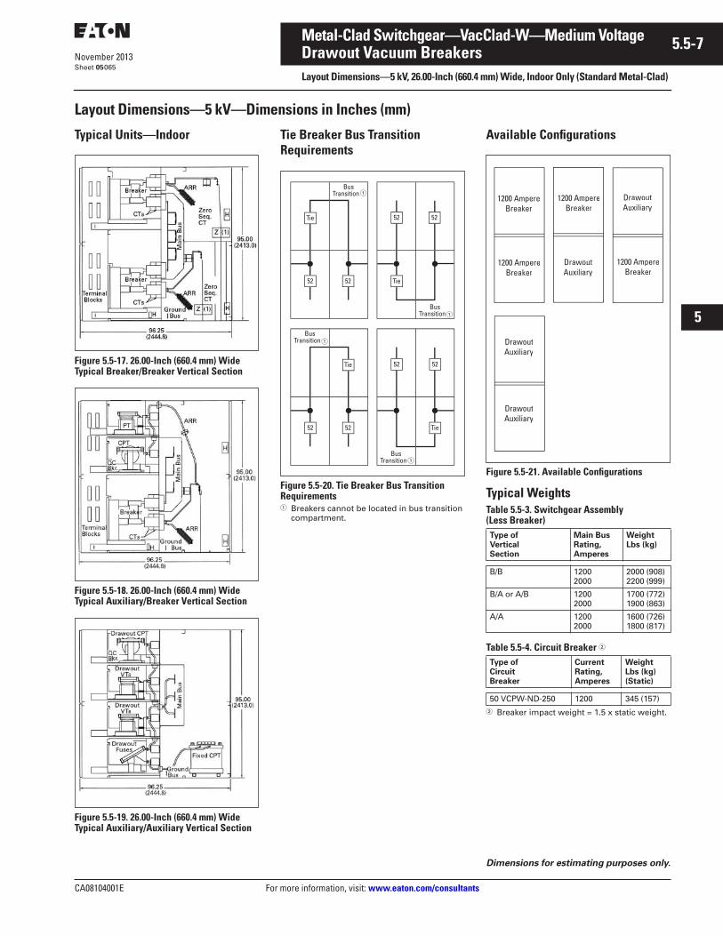
CA08104001E For more information, visit: www.eaton.com/consultants
5.5-7November 2013
Metal-Clad Switchgear—VacClad-W—Medium Voltage
i
ii
1
2
3
4
5
6
7
8
9
10
11
12
13
14
15
16
17
18
19
20
21
Sheet 05
Drawout Vacuum BreakersLayout Dimensions—5 kV, 26.00-Inch (660.4 mm) Wide, Indoor Only (Standard Metal-Clad)
065
Layout Dimensions—5 kV—Dimensions in Inches (mm)
Typical Units—Indoor
Figure 5.5-17. 26.00-Inch (660.4 mm) Wide Typical Breaker/Breaker Vertical Section
Figure 5.5-18. 26.00-Inch (660.4 mm) Wide Typical Auxiliary/Breaker Vertical Section
Figure 5.5-19. 26.00-Inch (660.4 mm) Wide Typical Auxiliary/Auxiliary Vertical Section
Tie Breaker Bus Transition Requirements
Figure 5.5-20. Tie Breaker Bus Transition Requirements� Breakers cannot be located in bus transition
compartment.
Available Configurations
Figure 5.5-21. Available Configurations
Typical WeightsTable 5.5-3. Switchgear Assembly (Less Breaker)
Table 5.5-4. Circuit Breaker �
� Breaker impact weight = 1.5 x static weight.
�
�
�
�
Type ofVerticalSection
Main BusRating,Amperes
WeightLbs (kg)
B/B 12002000
2000 (908)2200 (999)
B/A or A/B 12002000
1700 (772)1900 (863)
A/A 12002000
1600 (726)1800 (817)
Type ofCircuitBreaker
CurrentRating,Amperes
WeightLbs (kg)(Static)
50 VCPW-ND-250 1200 345 (157)
Dimensions for estimating purposes only.
1200 AmpereBreaker
1200 AmpereBreaker
DrawoutAuxiliary
1200 AmpereBreaker
DrawoutAuxiliary
DrawoutAuxiliary
DrawoutAuxiliary
1200 AmpereBreaker
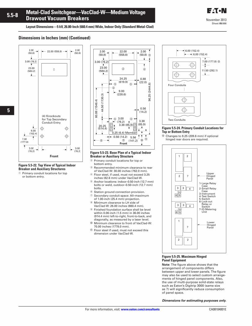
5.5-8
For more information, visit: www.eaton.com/consultants CA08104001E
November 2013
Metal-Clad Switchgear—VacClad-W—Medium Voltage
i
ii
1
2
3
4
5
6
7
8
9
10
11
12
13
14
15
16
17
18
19
20
21
Sheet 05
Drawout Vacuum BreakersLayout Dimensions—5 kV, 26.00-Inch (660.4 mm) Wide, Indoor Only (Standard Metal-Clad)
066
Dimensions in Inches (mm) (Continued)
Figure 5.5-22. Top View of Typical Indoor Breaker and Auxiliary Structures� Primary conduit locations for top
or bottom entry.
Figure 5.5-23. Base Plan of a Typical Indoor Breaker or Auxiliary Structure� Primary conduit locations for top or
bottom entry.� Recommended minimum clearance to rear
of VacClad-W: 30.00 inches (762.0 mm).� Floor steel, if used, must not exceed 3.25
inches (82.6 mm) under VacClad-W.� Anchor locations: indoor–0.50-inch (12.7 mm)
bolts or weld, outdoor–0.50-inch (12.7 mm) bolts.
� Station ground connection provision.� Secondary conduit space: All–maximum
of 1.00-inch (25.4 mm) projection.� Minimum clearance to LH side of
VacClad-W: 26.00 inches (660.4 mm). Finished foundation surface shall be level
within 0.06-inch (1.5 mm) in 36.00 inches (914.4 mm) left-to-right, front-to-back, and diagonally, as measured by a laser level.
� Minimum clearance to front of VacClad-W: 70.00 inches (1778.0 mm).
� Floor steel if used, must not exceed this dimension under VacClad-W.
Figure 5.5-24. Primary Conduit Locations for Top or Bottom Entry� Changes to 8.25 (209.6 mm) if optional
hinged rear doors are required.
Figure 5.5-25. Maximum Hinged Panel EquipmentNote: The figure above shows that the arrangement of components differs between upper and lower panels. The figure may also be used to select custom arrange-ments of hinged panel components. Also, the use of multi-purpose solid-state relays such as Eaton’s Digitrip 3000 (same size as 7) will significantly reduce consumption of panel space.
3.00(76.2)
23.00(584.2)
3.00 (76.2)
2.00(50.8)
➀
6.00(152.4)
(4) Knockoutsfor Top SecondarTT yConduit Entry
2.00(50.8)
3.00(76.2)
Front
7.00(177.8)
22.00 (558.8)
3.38 (85.9)3.38
(85.9)
5.56(141.2)
0.56(14.2)
3.00(76.2)
23.00(584.2)
22.00(558.8)
3.00 (76.2)
20.25(514.4)
0.25 (6.4) Member
96.2
5 (2
444.
8)
9.00(228.6)
2.00(50.8)
24.25(619.9)
60.8
8 (1
546.
4)
44.5
0 (1
130.
3)
0.56 (14.2)
2.00(50.8)
�
�
Front
�
�
��
�
�
�
��
�
�
�
0.88(22.0)
Dimensions for estimating purposes only.
11.50 (292.1)
Two Conduits
Four Conduits
7.00 (177.8)
6.00 (152.4)6.00 (152.4)
1 2
1
2 7
2 2
7
4
4
3 3
3 3
6 5
6 5
UpperHingedPanel
LowerHingedPanel
1-Large RelayCase
2-Small RelayCase
3-Instrument4-Test Switch5-Switch6-Lock-out
Relay orSwitch
7-IQ MeteringUnit
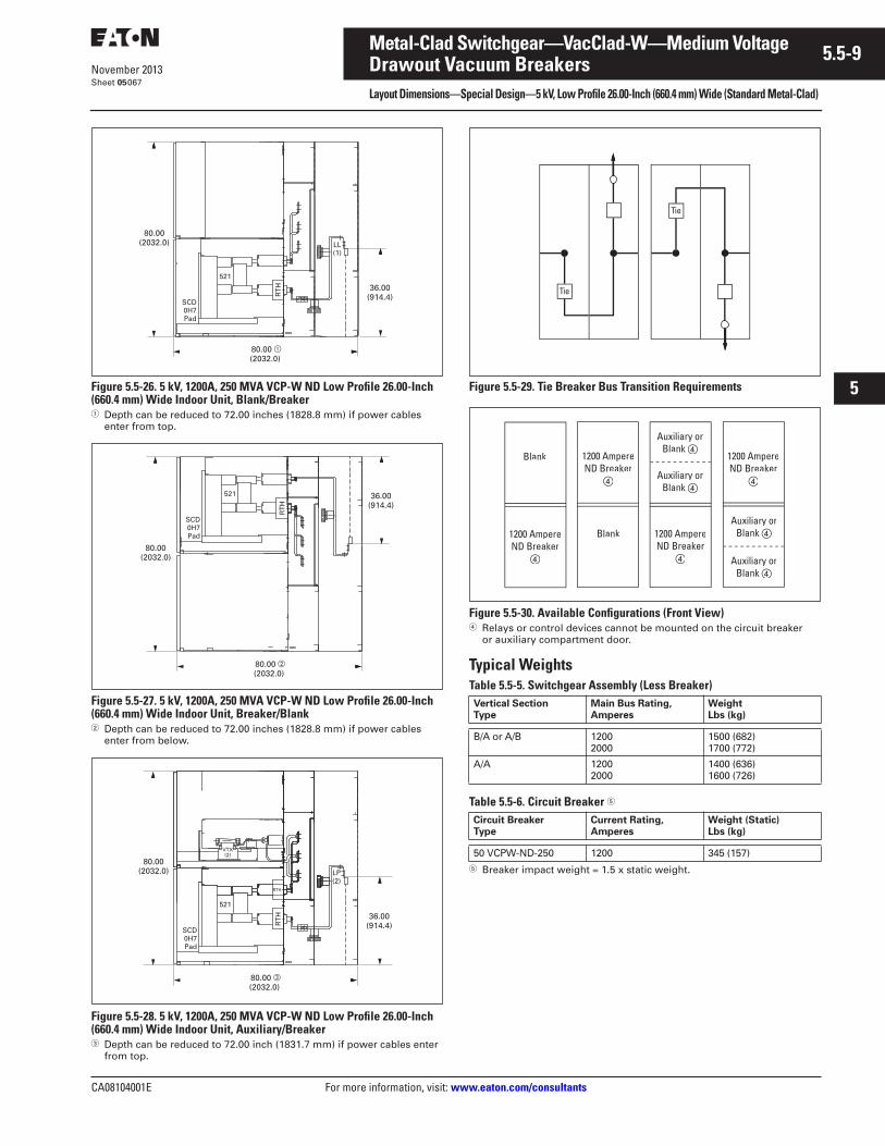
CA08104001E For more information, visit: www.eaton.com/consultants
5.5-9November 2013
Metal-Clad Switchgear—VacClad-W—Medium Voltage
i
ii
1
2
3
4
5
6
7
8
9
10
11
12
13
14
15
16
17
18
19
20
21
Sheet 05
Drawout Vacuum BreakersLayout Dimensions—Special Design—5 kV, Low Profile 26.00-Inch (660.4 mm) Wide (Standard Metal-Clad)
067
Figure 5.5-26. 5 kV, 1200A, 250 MVA VCP-W ND Low Profile 26.00-Inch (660.4 mm) Wide Indoor Unit, Blank/Breaker� Depth can be reduced to 72.00 inches (1828.8 mm) if power cables
enter from top.
Figure 5.5-27. 5 kV, 1200A, 250 MVA VCP-W ND Low Profile 26.00-Inch (660.4 mm) Wide Indoor Unit, Breaker/Blank� Depth can be reduced to 72.00 inches (1828.8 mm) if power cables
enter from below.
Figure 5.5-28. 5 kV, 1200A, 250 MVA VCP-W ND Low Profile 26.00-Inch (660.4 mm) Wide Indoor Unit, Auxiliary/Breaker� Depth can be reduced to 72.00 inch (1831.7 mm) if power cables enter
from top.
Figure 5.5-29. Tie Breaker Bus Transition Requirements
Figure 5.5-30. Available Configurations (Front View)� Relays or control devices cannot be mounted on the circuit breaker
or auxiliary compartment door.
Typical WeightsTable 5.5-5. Switchgear Assembly (Less Breaker)
Table 5.5-6. Circuit Breaker �
� Breaker impact weight = 1.5 x static weight.
36.00(914.4)
80.00 �(2032.0)
80.00(2032.0)
521
LL(1)
SCD0H7Pad
RT
H
36.00(914.4)
80.00 (2032.0)
80.00(2032.0)
521
SCD0H7Pad
RT
H
VTX(2)
36.00(914.4)
80.00 (2032.0)
80.00(2032.0)
521
LP(2)
SCD0H7Pad
RT
H
RTH
Vertical SectionType
Main Bus Rating,Amperes
WeightLbs (kg)
B/A or A/B 12002000
1500 (682)1700 (772)
A/A 12002000
1400 (636)1600 (726)
Circuit BreakerType
Current Rating,Amperes
Weight (Static)Lbs (kg)
50 VCPW-ND-250 1200 345 (157)
Blank
1200 AmpereND Breaker
�
1200 AmpereND Breaker
�
Blank
1200 AmpereND Breaker
�
Auxiliary orBlank �
Auxiliary orBlank �
Auxiliary orBlank �
Auxiliary orBlank �
1200 AmpereND Breaker
�
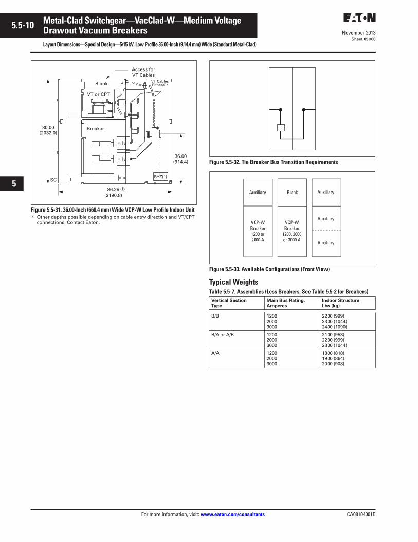
5.5-10
For more information, visit: www.eaton.com/consultants CA08104001E
November 2013
Metal-Clad Switchgear—VacClad-W—Medium Voltage
i
ii
1
2
3
4
5
6
7
8
9
10
11
12
13
14
15
16
17
18
19
20
21
Sheet 05
Drawout Vacuum BreakersLayout Dimensions—Special Design—5/15 kV, Low Profile 36.00-Inch (9.14.4 mm) Wide (Standard Metal-Clad)
068
Figure 5.5-31. 36.00-Inch (660.4 mm) Wide VCP-W Low Profile Indoor Unit� Other depths possible depending on cable entry direction and VT/CPT
connections. Contact Eaton.
Figure 5.5-32. Tie Breaker Bus Transition Requirements
Figure 5.5-33. Available Configurations (Front View)
Typical WeightsTable 5.5-7. Assemblies (Less Breakers, See Table 5.5-2 for Breakers)
36.00(914.4)
86.25 �(2190.8)
80.00(2032.0)
Blank
VT or CPT
CT
CT
CT
CT
Breaker
HTR BYZ(1)
VT CablesEither/Or
SC
Access for VT Cables
Vertical SectionType
Main Bus Rating,Amperes
Indoor StructureLbs (kg)
B/B 120020003000
2200 (999)2300 (1044)2400 (1090)
B/A or A/B 120020003000
2100 (953)2200 (999)2300 (1044)
A/A 120020003000
1800 (818)1900 (864)2000 (908)
VCP-WBreaker1200 or2000 A
Blank
Auxiliary
Auxiliary
Auxiliary Auxiliary
VCP-WBreaker
1200, 2000or 3000 A
CA08104001E For more information, visit: www.eaton.com/consultants
5.5-11November 2013
Metal-Clad Switchgear—VacClad-W—Medium Voltage
i
ii
1
2
3
4
5
6
7
8
9
10
11
12
13
14
15
16
17
18
19
20
21
Sheet 05
Drawout Vacuum BreakersLayout Dimensions—27 kV, 36.00-Inch (914.4 mm) Wide (Standard Metal-Clad), One-High Design
069
Layout Dimensions—27 kV One-High Design—Dimensions in Inches (mm)
Typical Units
Figure 5.5-34. Indoor 36.00-Inch (914.4 mm) Wide Typical Auxiliary/Breaker Vertical Section
Figure 5.5-35. Outdoor AislelessTypical Auxiliary/Breaker Vertical Section
Figure 5.5-36. Indoor Auxiliaries36.00-Inch (914.4 mm) Wide Typical Auxiliary/Auxiliary Vertical Section
Typical Weights in Lbs (kg)Table 5.5-8. Assemblies (Less Breakers)
Table 5.5-9. Breaker Weights in Lbs (kg) �
� Breaker impact = 1.5 x breaker weight.
Available Configurations
Figure 5.5-37. Available Configurations
Dimensions for estimating purposes only.
Type ofVerticalSection
Main BusRatingAmperes
Indoor OutdoorAisleless
A/B 12002000
2500 (1135)2600 (1180)
3400 (1545)3500 (1591)
A/A 12002000
2200 (999)2300 (1045)
2800 (1271)2900 (1317)
Type ofBreaker
Current Rating,Amperes
1200 2000
270 VCP-W 750270 VCP-W 1000
415 (188)415 (188)
475 (216)475 (216)
270 VCP-W 1250, 25C270 VCP-W 40, 40C
415 (188)415 (188)
475 (216)475 (216)
DrawoutVTsTT
1200 AmpereBreaker
DrawoutVTsTT
2000 AmpereBreaker
DrawoutVTsTT
DrawoutVTsTT
DrawoutFuses
FixedCPT
5.5-12
For more information, visit: www.eaton.com/consultants CA08104001E
November 2013
Metal-Clad Switchgear—VacClad-W—Medium Voltage
i
ii
1
2
3
4
5
6
7
8
9
10
11
12
13
14
15
16
17
18
19
20
21
Sheet 05
Drawout Vacuum BreakersLayout Dimensions—27 kV, 36.00-Inch (914.4 mm) Wide (Standard Metal-Clad), One-High Design
070
Dimensions in Inches (mm) (Continued)
Figure 5.5-38. Top View of Typical Indoor Breaker and Auxiliary Structures� Primary conduit locations for top or
bottom entry.
Figure 5.5-39. Base Plan of a Typical Indoor Breaker or Auxiliary Structure� Primary conduit locations for top or
bottom entry.� Recommended minimum clearance to rear
of VacClad-W: 36.00 inches (914.4 mm).� Floor steel, if used, must not exceed
3.25 inches (82.6 mm) under VacClad-W.� Anchor locations: indoor—0.50-inch
(12.7 mm) bolts or weld, outdoor—0.50-inch (12.7 mm) bolts.
� Station ground connection provision.� Secondary conduit space: All—maximum
of 1.00-inch (25.4 mm) projection.� Minimum clearance to LH side of
VacClad-W: 32.00 inches (812.8 mm). Finished foundation surface shall be level
within 0.06-inch (1.5 mm) in 36.00 inches (914.4 mm) left-to-right, front-to-back, and diagonally, as measured by a laser level.
� Minimum clearance to front of VacClad-W: 72.00 inches (1828.8 mm).
� Floor steel if used, must not exceed this dimension under VacClad-W.
Note: Outdoor Aisleless Base Plan—27 kV switchgear outdoor Aisleless base plan details are same as 5/15 kV outdoor Aisleless switchgear. Refer to Figure 5.5-14.
Figure 5.5-40. Primary Conduit Locations for Top or Bottom Entry� Changes to 8.25 inches (209.6 mm) if
optional hinged rear doors are required.
Figure 5.5-41. Maximum Hinged Panel EquipmentNote: The figure above shows that the arrangement of components differs between upper and lower panels. The figure may also be used to select custom arrange-ments of hinged panel components. Also, the use of multi-purpose solid-state relays such as Eaton’s Digitrip 3000 (same size as device 7) will significantly reduce consumption of panel space.
23.00(584.2)
32.00 (812.8)
3.00 (76.2)
(2) Knockoutsfor Top SecondarTT yConduit Entry
8 508.50(215.9)(215 9)
2.00 (50.8) 2.00 (50.8)
3 003.00(76.2)
3.00(76.2)
Front
3.88 (98.6)
3.88(98.6)
5.56(141.2)
0.56(14.2)
3.00(76.2)
23.00(584.2)
32.00 (812.8)
3.00 (76.2)
15.50(393.7)
96.2
5 (2
444.
8)9.00 (228.6)
2.00 (50.8)
34.25(870.0)
59.3
1 (1
506.
5)
34 (
863.
6)
0.56 (14.2)
2.00 (50.8)
Front
0.25 (6.35) Member
0.88(22.0)
Dimensions for estimating purposes only.
11.50 (292.1)
Two Conduits
Four Conduits
7.00 (177.8)
6.00 (152.4)6.00 (152.4)
1 1 1 21 1
2 2 2 72 2
4
4
3 3 3 3 33 3
6 5 5
UpperHingedPanel
LowerHingedPanel
1-Large RelayCase
2-Small Relay
3-Instrument
tRelay or
7-IQ MeteringUnitNo devices on the
breaker compartmentdoor.

CA08104001E For more information, visit: www.eaton.com/consultants
5.5-13November 2013
Metal-Clad Switchgear—VacClad-W—Medium Voltage
i
ii
1
2
3
4
5
6
7
8
9
10
11
12
13
14
15
16
17
18
19
20
21
Sheet 05
Drawout Vacuum BreakersLayout Dimensions—27 kV Two-High Design
071
Layout Dimensions—27 kV Two-High Design—Dimensions in Inches (mm)
Typical Units—Indoor �
Figure 5.5-42. Indoor 36.00-Inch (914.4 mm) Wide Typical Breaker-over-Breaker Vertical Section� For 1-high arrangement (1 breaker per cell),
depth may be reduced to 108.64 inches(2759.5 mm).
Figure 5.5-43. 36.00-Inch (914.4 mm) Wide Typical Auxiliary-over-Breaker Vertical Section
Available Configurations �
Figure 5.5-44. Available Configurations� Available Main Bus Ratings for 27 kV two-high design are 1200A, 2000A, 2500A or 2700A.� Bus connected, maximum 4A fuses. CPT is installed remote from the switchgear.� Fuses are bus or line connected. CPT is installed in front bottom, on drawout frame.
Maximum CPT size is single-phase 37.5 kVA or three-phase 45 kVA.� Bus or Line connected, maximum 4A fuses. CPT is installed remote from the switchgear.
Blank 1200 AmpereBreaker
1200 AmpereBreaker
1200 AmpereBreaker
DrawoutVTsTT
DrawoutVTs
Blank
DrawoutVTs
DrawoutVTs
DrawoutVTs
CPT PrimaryFuse Drawer
1200 Ampereor
2000 AmpereBreaker
1200 Ampereor
2000 AmpereBreaker
CPT PrimaryFuse Drawer
CPT PrimaryFuse Drawer
CPT PrimaryFuse Drawer
1200 Ampereor
2000 AmpereBreaker
1200 Ampereor
2000 AmpereBreaker
Blank DrawoutVTsTT
CPT
Blank
BlankBlank
H100.00
(2540.0)
36.00(914.4)
H100.00
(2540.0)
�
� � �
�
Tie Breaker Bus Transition Requirements
Figure 5.5-45. Tie Breaker Bus Transition Requirements� Breakers cannot be located in bus transition
compartment.
Typical WeightsTable 5.5-10. Assemblies (Less Breakers) �
� Refer to Table 5.5-9 for breaker weights.
Type ofVerticalSection
Main BusRating,Amperes
WeightLbs (kg)
Aux/Bkr 1200200025002700
2500 (1135)2600 (1180)2600 (1180)2700 (1227)
Aux/Aux 1200200025002700
2200 (1000)2300 (1046)2300 (1046)2400 (1091)
Bkr/Bkr 1200200025002700
2700 (1227)2800 (1273)2800 (1273)2900 (1318)
Dimensions for estimating purposes only.
�
�
�
�
5.5-14
For more information, visit: www.eaton.com/consultants CA08104001E
November 2013
Metal-Clad Switchgear—VacClad-W—Medium Voltage
i
ii
1
2
3
4
5
6
7
8
9
10
11
12
13
14
15
16
17
18
19
20
21
Sheet 05
Drawout Vacuum BreakersTypical Floor Plan—27 kV Two-High, Indoor
072
Typical Floor Plan—27 kV Two-High, Indoor
Figure 5.5-46. Typical Floor Plan—27 kV Two-High, Indoor
10.96(278.4)
10
36.00(914.4)
Front
0.59(15.0)
0.59(15.0)
1.32(33.5)
2 7.00(177.8)
8
36.00(914.4)Min.
BusCompt.
118.64(3013.5)
LineCompt.
5
32.00(812.8)
Rear
48.00(1219.2)
9.00(228.6)
0.88(22.4)
2.00(50.8)
2.00(50.8)
1
1
910
6
3.00(76.2)
72.00(1828.8)
Min.
3
7
10
9
7.38(187.5)
1
65.97(1675.6)
6
8
7
5
4
3
2A
A
3.00(76.2)
4.25(108.0)
7.80(198.1)
1.00(25.4)
1
1
1
222.25
(565.2)
BreakerCompt.
Supplied by Customer
ControlCompt.
Section A-A
Knockouts for 1.38" (35.1)or 1.75 (44.5) Conduits
Top Entry Secondary Control
Anchor locations for 0.50-inch (12.7 mm) bolts SAE Grade 5 or better, (6) places in each vertical section.
Secondary control wiring conduit openings, conduit projection must not exceed 1.00 inch (25.4 mm).
Minimum front clearance when using Eaton’s portable lifter.
Minimum left-hinged panel clearance.
Recommended minimum rear clearance.
Finished foundation surface shall be level within 0.06-inch (1.5 mm) in 36.00 inches (914.4 mm) left-to-right, front-to-back, and diagonally, as measured by a laser level.
4.25 inches (108.0 mm) maximum dimension under the front of the switchgear must not be exceeded to avoid interference with secondary conduits.
Primary (H.V.) conduit projection must not exceed 2.00 inches (50.8 mm). See shop order base plan for conduit locations.
Customer's ground provisions, provided as shown by symbol on shop order sectional side views.
5.00 inches (127.0 mm) minimum foundation supports for attaching switchgear.
32.00(812.8)Min.4
32.00(812.8)
2.00(50.8)
0.88(22.4)
3.00(76.2)
3.00(76.2)
36.00(914.4)
3.00(76.2)
3.00(76.2)
Dimensions for estimating purposes only.
CA08104001E For more information, visit: www.eaton.com/consultants
5.5-15November 2013
Metal-Clad Switchgear—VacClad-W—Medium Voltage
i
ii
1
2
3
4
5
6
7
8
9
10
11
12
13
14
15
16
17
18
19
20
21
Sheet 05
Drawout Vacuum BreakersLayout Dimensions—38 kV, 150 kV BIL Design
073
Layout Dimensions—38 kV, 150 kV BIL Design—Dimensions in Inches (mm)
Typical Units
Figure 5.5-47. Indoor—Typical Breaker, Main or Feeder
Figure 5.5-48. Indoor—Typical Auxiliary-Over-Auxiliary
Figure 5.5-49. Indoor—Typical Bus Tie Breaker
Typical Weights in Lbs (kg) �
Table 5.5-11. Assemblies (Less Breakers)
� Refer to Table 5.5-12 for breaker weights.
Table 5.5-12. Breaker Weights in Lbs (kg)
Type ofVerticalSection
Main BusRatingAmperes
Indoor
Breaker 120020002500
3100 (1409)3200 (1455)3355 (1525)
Auxiliary 120020002500
3000 (1364)3100 (1409)3355 (1525)
Type ofBreaker
Current Rating, Amperes
1200 2000
380 VCP-W-16, 16C380 VCP-W-25, 25C
1080 (490)1080 (490)
1140 (518)1140 (518)
380 VCP-W-32, 32C380 VCP-W-21
1080 (490)1080 (490)
1140 (518)1140 (518)
380 VCP-W-40, 40C 1080 (490)1080 (490)
1140 (518)1140 (518)
Dimensions for estimating purposes only.
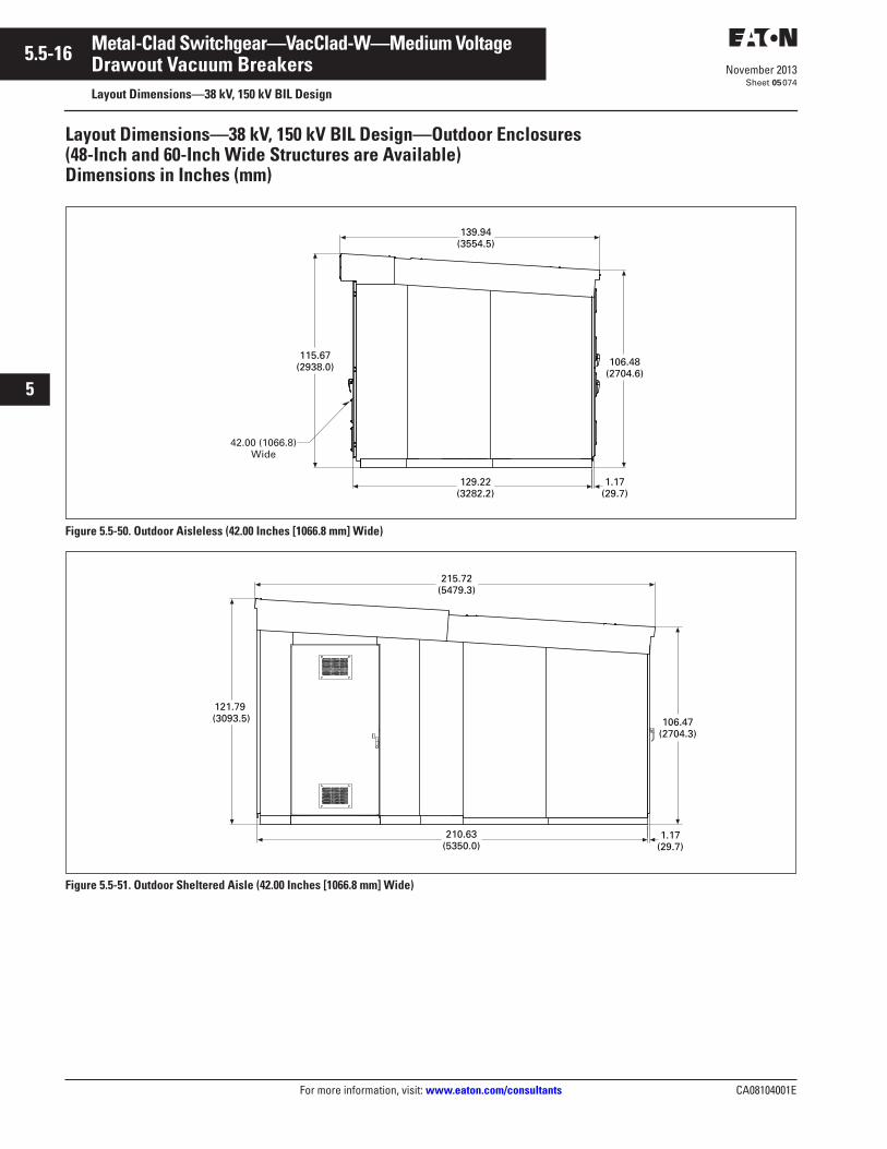
5.5-16
For more information, visit: www.eaton.com/consultants CA08104001E
November 2013
Metal-Clad Switchgear—VacClad-W—Medium Voltage
i
ii
1
2
3
4
5
6
7
8
9
10
11
12
13
14
15
16
17
18
19
20
21
Sheet 05
Drawout Vacuum BreakersLayout Dimensions—38 kV, 150 kV BIL Design
074
Layout Dimensions—38 kV, 150 kV BIL Design—Outdoor Enclosures(48-Inch and 60-Inch Wide Structures are Available)Dimensions in Inches (mm)
Figure 5.5-50. Outdoor Aisleless (42.00 Inches [1066.8 mm] Wide)
Figure 5.5-51. Outdoor Sheltered Aisle (42.00 Inches [1066.8 mm] Wide)
129.22(3282.2)
115.67(2938.0)
139.94(3554.5)
106.48(2704.6)
42.00 (1066.8)Wide
1.17(29.7)
210.63(5350.0)
1.17(29.7)
106.47(2704.3)
121.79 (3093.5)
215.72(5479.3)
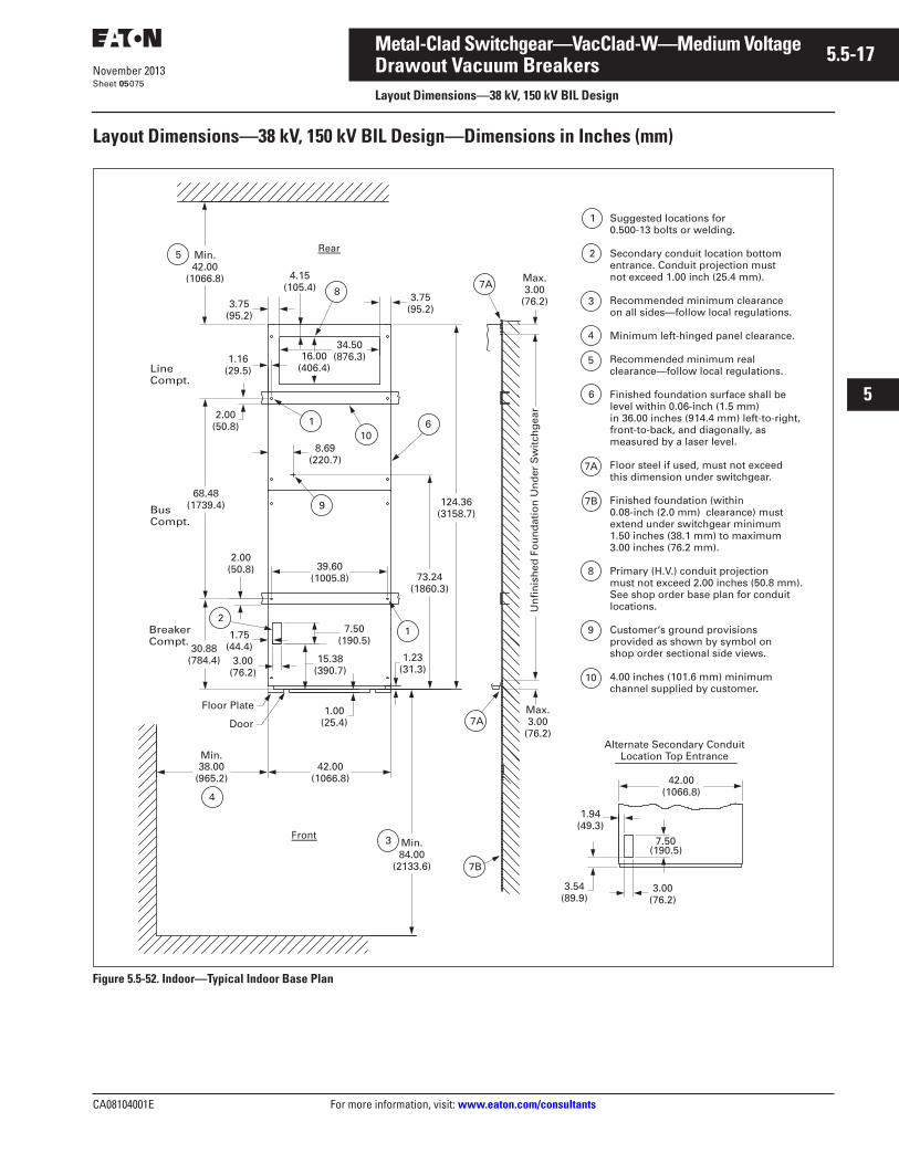
CA08104001E For more information, visit: www.eaton.com/consultants
5.5-17November 2013
Metal-Clad Switchgear—VacClad-W—Medium Voltage
i
ii
1
2
3
4
5
6
7
8
9
10
11
12
13
14
15
16
17
18
19
20
21
Sheet 05
Drawout Vacuum BreakersLayout Dimensions—38 kV, 150 kV BIL Design
075
Layout Dimensions—38 kV, 150 kV BIL Design—Dimensions in Inches (mm)
Figure 5.5-52. Indoor—Typical Indoor Base Plan
1
30.88(784.4)
7.50(190.5)
73.24(1860.3)
124.36(3158.7)
Un
fin
ish
ed F
ou
nd
atio
n U
nd
er S
wit
chg
ear
3.54(89.9)
Min.84.00
(2133.6)
Front 3
7B
42.00(1066.8)
4
38.00(965.2)
Min.
1.75(44.4)
3.00(76.2)
15.38(390.7)
1.23(31.3)
1.94(49.3)
7.50(190.5)
3.00(76.2)
42.00(1066.8)
Alternate Secondary ConduitLocation Top Entrance
Min.42.00
(1066.8)
68.48(1739.4)
8.69(220.7)
39.60(1005.8)
2.00(50.8)
2
9
34.50(876.3)16.00
(406.4)1.16
(29.5)
2.00(50.8)
LineCompt.
BusCompt.
1
3.75(95.2)
8
10
3.75(95.2)
7A
5Rear
Door
Floor Plate 1.00(25.4)
BreakerCompt.
Max.3.00
(76.2)
Max.3.00
(76.2)
Suggested locations for 0.500-13 bolts or welding.
Secondary conduit location bottom entrance. Conduit projection mustnot exceed 1.00 inch (25.4 mm).
Recommended minimum clearance on all sides—follow local regulations.
Minimum left-hinged panel clearance.
Recommended minimum real clearance—follow local regulations.
Finished foundation surface shall be level within 0.06-inch (1.5 mm) in 36.00 inches (914.4 mm) left-to-right, front-to-back, and diagonally, as measured by a laser level.
Floor steel if used, must not exceed this dimension under switchgear.
Finished foundation (within 0.08-inch (2.0 mm) clearance) must extend under switchgear minimum 1.50 inches (38.1 mm) to maximum 3.00 inches (76.2 mm).
Primary (H.V.) conduit projection must not exceed 2.00 inches (50.8 mm). See shop order base plan for conduit locations.
Customer‘s ground provisions provided as shown by symbol on shop order sectional side views.
4.00 inches (101.6 mm) minimum channel supplied by customer.
6
7A
4.15(105.4)
8
7B
7A
6
5
4
1
3
2
9
10
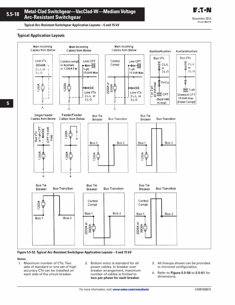
5.5-18
For more information, visit: www.eaton.com/consultants CA08104001E
November 2013
Metal-Clad Switchgear—VacClad-W—Medium Voltage
i
ii
1
2
3
4
5
6
7
8
9
10
11
12
13
14
15
16
17
18
19
20
21
Sheet 05
Arc-Resistant SwitchgearTypical Arc-Resistant Switchgear Application Layouts—5 and 15 kV
076
Typical Application Layouts
Figure 5.5-53. Typical Arc-Resistant Switchgear Application Layouts—5 and 15 kV
Notes:
1. Maximum number of CTs: Two sets of standard or one set of high accuracy CTs can be installed on each side of the circuit breaker.
2. Bottom entry is standard for all power cables. In breaker over breaker arrangement, maximum number of cables is limited to two per phase for each breaker.
3. All lineups shown can be provided in mirrored configuration.
4. Refer to Figure 5.5-56 to 5.5-61 for dimensions.
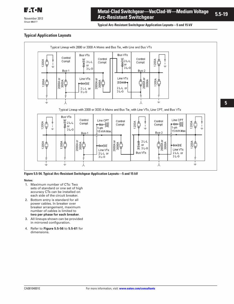
CA08104001E For more information, visit: www.eaton.com/consultants
5.5-19November 2013
Metal-Clad Switchgear—VacClad-W—Medium Voltage
i
ii
1
2
3
4
5
6
7
8
9
10
11
12
13
14
15
16
17
18
19
20
21
Sheet 05
Arc-Resistant SwitchgearTypical Arc-Resistant Switchgear Application Layouts—5 and 15 kV
077
Typical Application Layouts
Figure 5.5-54. Typical Arc-Resistant Switchgear Application Layouts—5 and 15 kV
Notes:
1. Maximum number of CTs: Two sets of standard or one set of high accuracy CTs can be installed on each side of the circuit breaker.
2. Bottom entry is standard for all power cables. In breaker over breaker arrangement, maximum number of cables is limited to two per phase for each breaker.
3. All lineups shown can be provided in mirrored configuration.
4. Refer to Figure 5.5-56 to 5.5-61 for dimensions.
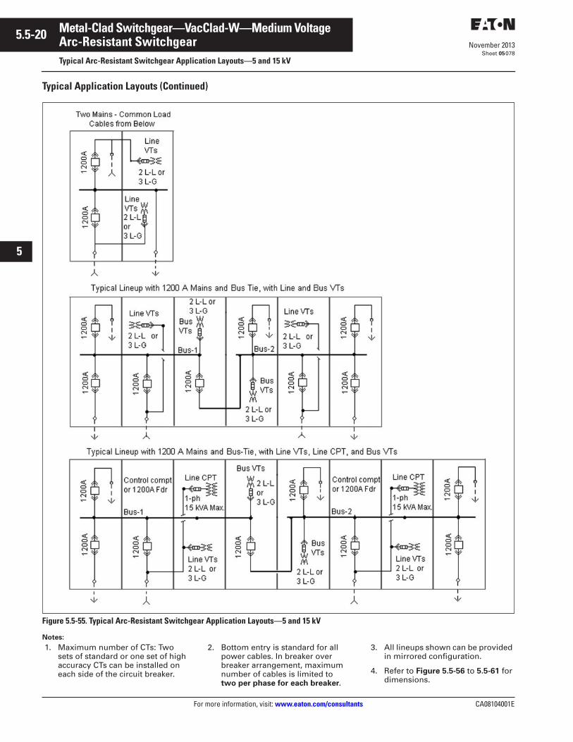
5.5-20
For more information, visit: www.eaton.com/consultants CA08104001E
November 2013
Metal-Clad Switchgear—VacClad-W—Medium Voltage
i
ii
1
2
3
4
5
6
7
8
9
10
11
12
13
14
15
16
17
18
19
20
21
Sheet 05
Arc-Resistant SwitchgearTypical Arc-Resistant Switchgear Application Layouts—5 and 15 kV
078
Typical Application Layouts (Continued)
Figure 5.5-55. Typical Arc-Resistant Switchgear Application Layouts—5 and 15 kV
Notes:
1. Maximum number of CTs: Two sets of standard or one set of high accuracy CTs can be installed on each side of the circuit breaker.
2. Bottom entry is standard for all power cables. In breaker over breaker arrangement, maximum number of cables is limited to two per phase for each breaker.
3. All lineups shown can be provided in mirrored configuration.
4. Refer to Figure 5.5-56 to 5.5-61 for dimensions.
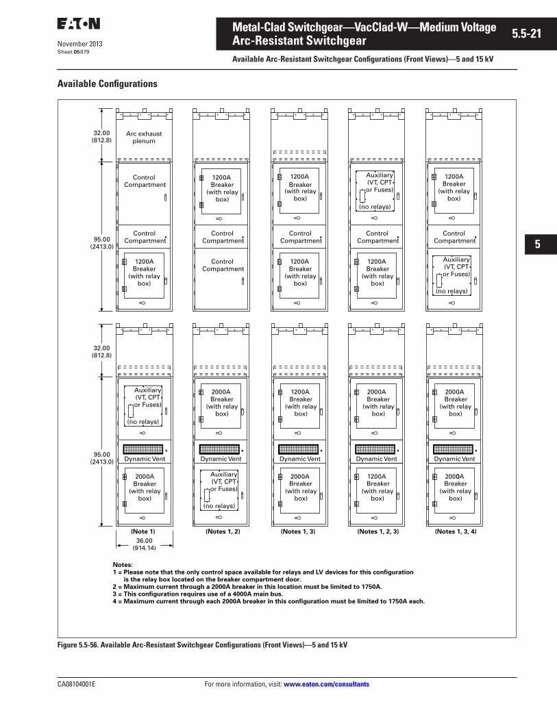
CA08104001E For more information, visit: www.eaton.com/consultants
5.5-21November 2013
Metal-Clad Switchgear—VacClad-W—Medium Voltage
i
ii
1
2
3
4
5
6
7
8
9
10
11
12
13
14
15
16
17
18
19
20
21
Sheet 05
Arc-Resistant SwitchgearAvailable Arc-Resistant Switchgear Configurations (Front Views)—5 and 15 kV
079
Available Configurations
Figure 5.5-56. Available Arc-Resistant Switchgear Configurations (Front Views)—5 and 15 kV
Arc exhaustplenum
Control
ControlCompartment
1200ABreaker
(with relay box)
1200A
(with relay box)
1200A
(with relay box)
1200ABreaker
(with relay box)
1200ABreaker
(with relay box)
1200A
(with relay box)
Auxiliary(VT, CPT or Fuses)
(no relays)
Auxiliary(VT, CPT or Fuses)
(no relays)
Dynamic Vent
2000ABreaker
(with relay box)
Auxiliary(VT, CPT or Fuses)
(no relays)
Dynamic Vent
Auxiliary(VT, CPT or Fuses)
(no relays)
Dynamic Vent
2000A
(with relay box)
1200A
(with relay box)
Dynamic Vent
1200A
(with relay box)
2000A
(with relay box)
Dynamic Vent
20000A
(with relay box)
2000A
(with relay box)
32.00(812.8)
95.00(2413.0)
32.00(812.8)
95.00(2413.0)
36.00(914.14)
Notes:1 = Please note that the only control space available for relays and LV devices for this configuration is the relay box located on the breaker compartment door.2 = Maximum current through a 2000A breaker in this location must be limited to 1750A.3 = This configuration requires use of a 4000A main bus.4 = Maximum current through each 2000A breaker in this configuration must be limited to 1750A each.
(Note 1) (Notes 1, 2) (Notes 1, 3) (Notes 1, 2, 3) (Notes 1, 3, 4)
CompartmentControl
CompartmentControl
CompartmentControl
Compartment
Breaker
ControlCompartment Breaker
ControlCompartment
Breaker
Breaker Breaker
Breaker Breaker
Breaker
Breaker
2000A
(with relay box)
Breaker
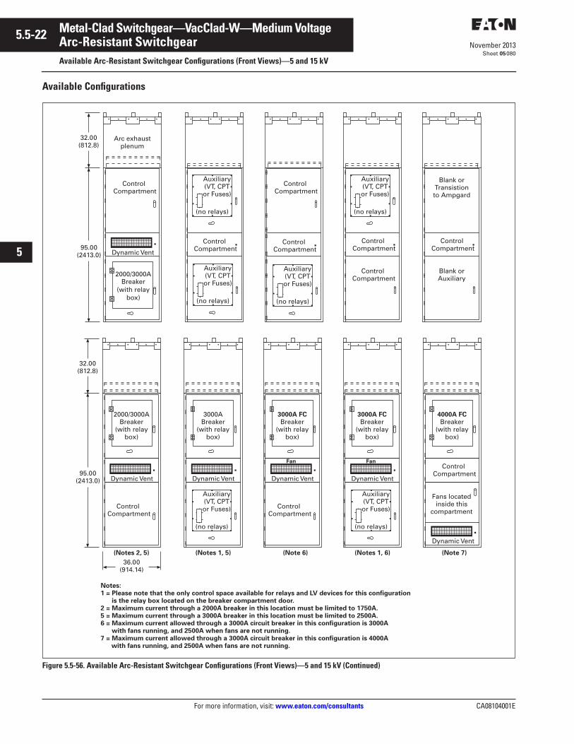
5.5-22
For more information, visit: www.eaton.com/consultants CA08104001E
November 2013
Metal-Clad Switchgear—VacClad-W—Medium Voltage
i
ii
1
2
3
4
5
6
7
8
9
10
11
12
13
14
15
16
17
18
19
20
21
Sheet 05
Arc-Resistant SwitchgearAvailable Arc-Resistant Switchgear Configurations (Front Views)—5 and 15 kV
080
Available Configurations
Figure 5.5-56. Available Arc-Resistant Switchgear Configurations (Front Views)—5 and 15 kV (Continued)
Dynamic Vent
32.00(812.8)
95.00(2413.0)
Auxiliary(VT, CPT or Fuses)
(no relays)
Auxiliary(VT, CPT or Fuses)
(no relays)
Auxiliary(VT, CPT or Fuses)
(no relays)
Arc exhaustplenum
2000/3000ABreaker
(with relaybox)
Dynamic Vent
Auxiliary(VT, CPT or Fuses)
(no relays)
Blank or Transistion to Ampgard
Blank or Auxiliary
2000/3000ABreaker
(with relay box)
Dynamic Vent
3000A FCBreaker
(with relay box)
Dynamic Vent
3000ABreaker
(with relay box)
Auxiliary(VT, CPT or Fuses)
(no relays)
Auxiliary(VT, CPT or Fuses)
(no relays)
Fan
Dynamic Vent
3000A FCBreaker
(with relay box)
Fan
Dynamic Vent
4000A FCBreaker
(with relay box)
Fans located inside this
compartment
32.00(812.8)
95.00(2413.0)
36.00(914.14)
Notes:1 = Please note that the only control space available for relays and LV devices for this configuration is the relay box located on the breaker compartment door.2 = Maximum current through a 2000A breaker in this location must be limited to 1750A.5 = Maximum current through a 3000A breaker in this location must be limited to 2500A.6 = Maximum current allowed through a 3000A circuit breaker in this configuration is 3000A with fans running, and 2500A when fans are not running.7 = Maximum current allowed through a 3000A circuit breaker in this configuration is 4000A with fans running, and 2500A when fans are not running.
(Notes 2, 5) (Notes 1, 5) (Notes 1, 6)(Note 6) (Note 7)
ControlCompartment
ControlCompartment
ControlCompartment
ControlCompartment
ControlCompartment
ControlCompartment
ControlCompartment
ControlCompartment
ControlCompartment
ControlCompartment
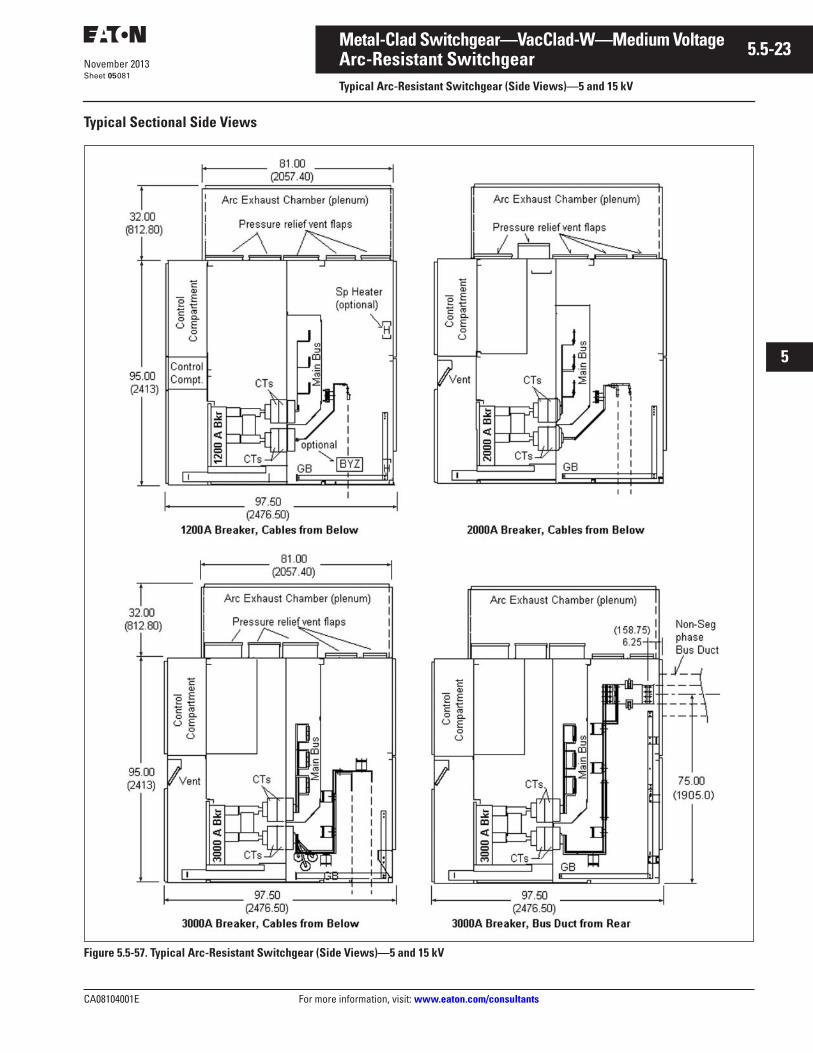
CA08104001E For more information, visit: www.eaton.com/consultants
5.5-23November 2013
Metal-Clad Switchgear—VacClad-W—Medium Voltage
i
ii
1
2
3
4
5
6
7
8
9
10
11
12
13
14
15
16
17
18
19
20
21
Sheet 05
Arc-Resistant SwitchgearTypical Arc-Resistant Switchgear (Side Views)—5 and 15 kV
081
Typical Sectional Side Views
Figure 5.5-57. Typical Arc-Resistant Switchgear (Side Views)—5 and 15 kV
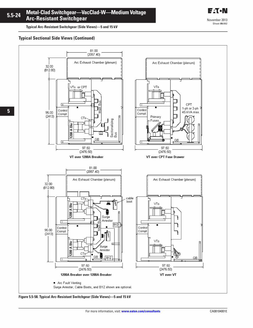
5.5-24
For more information, visit: www.eaton.com/consultants CA08104001E
November 2013
Metal-Clad Switchgear—VacClad-W—Medium Voltage
i
ii
1
2
3
4
5
6
7
8
9
10
11
12
13
14
15
16
17
18
19
20
21
Sheet 05
Arc-Resistant SwitchgearTypical Arc-Resistant Switchgear (Side Views)—5 and 15 kV
082
Typical Sectional Side Views (Continued)
Figure 5.5-58. Typical Arc-Resistant Switchgear (Side Views)—5 and 15 kV
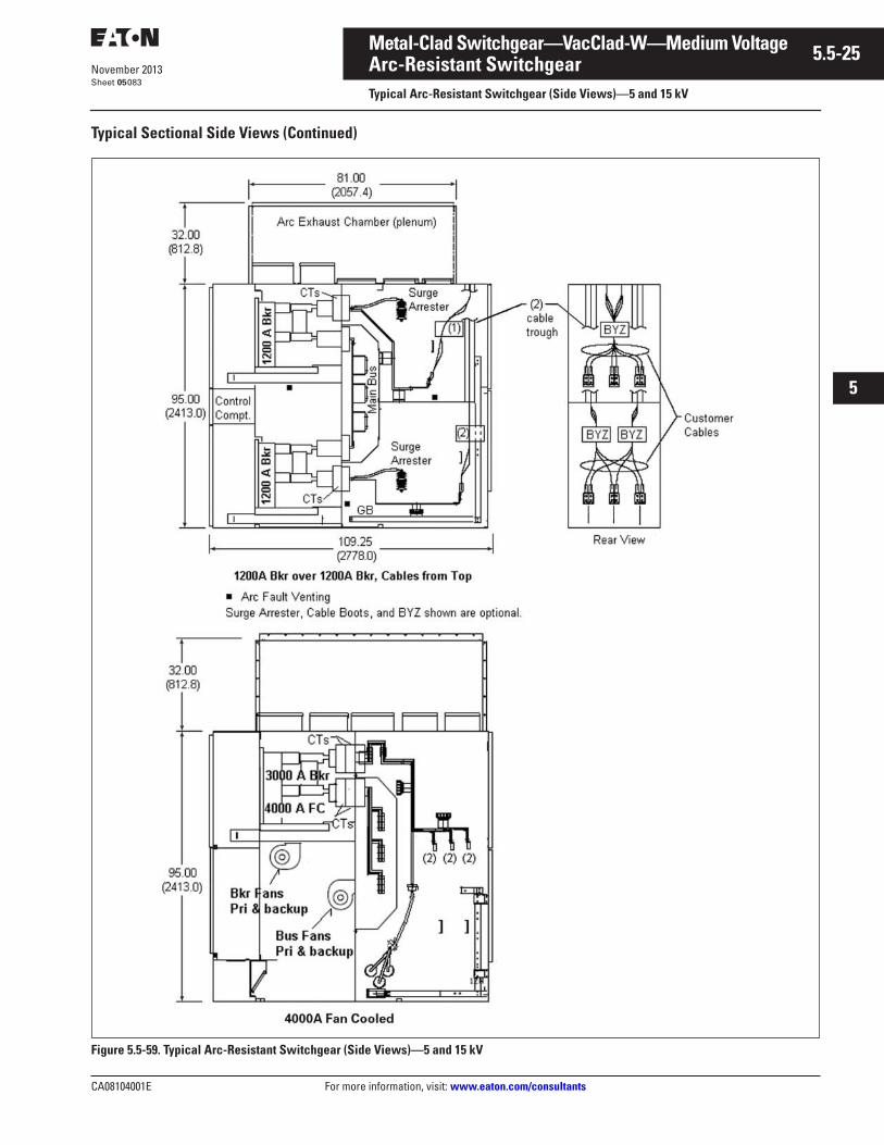
CA08104001E For more information, visit: www.eaton.com/consultants
5.5-25November 2013
Metal-Clad Switchgear—VacClad-W—Medium Voltage
i
ii
1
2
3
4
5
6
7
8
9
10
11
12
13
14
15
16
17
18
19
20
21
Sheet 05
Arc-Resistant SwitchgearTypical Arc-Resistant Switchgear (Side Views)—5 and 15 kV
083
Typical Sectional Side Views (Continued)
Figure 5.5-59. Typical Arc-Resistant Switchgear (Side Views)—5 and 15 kV
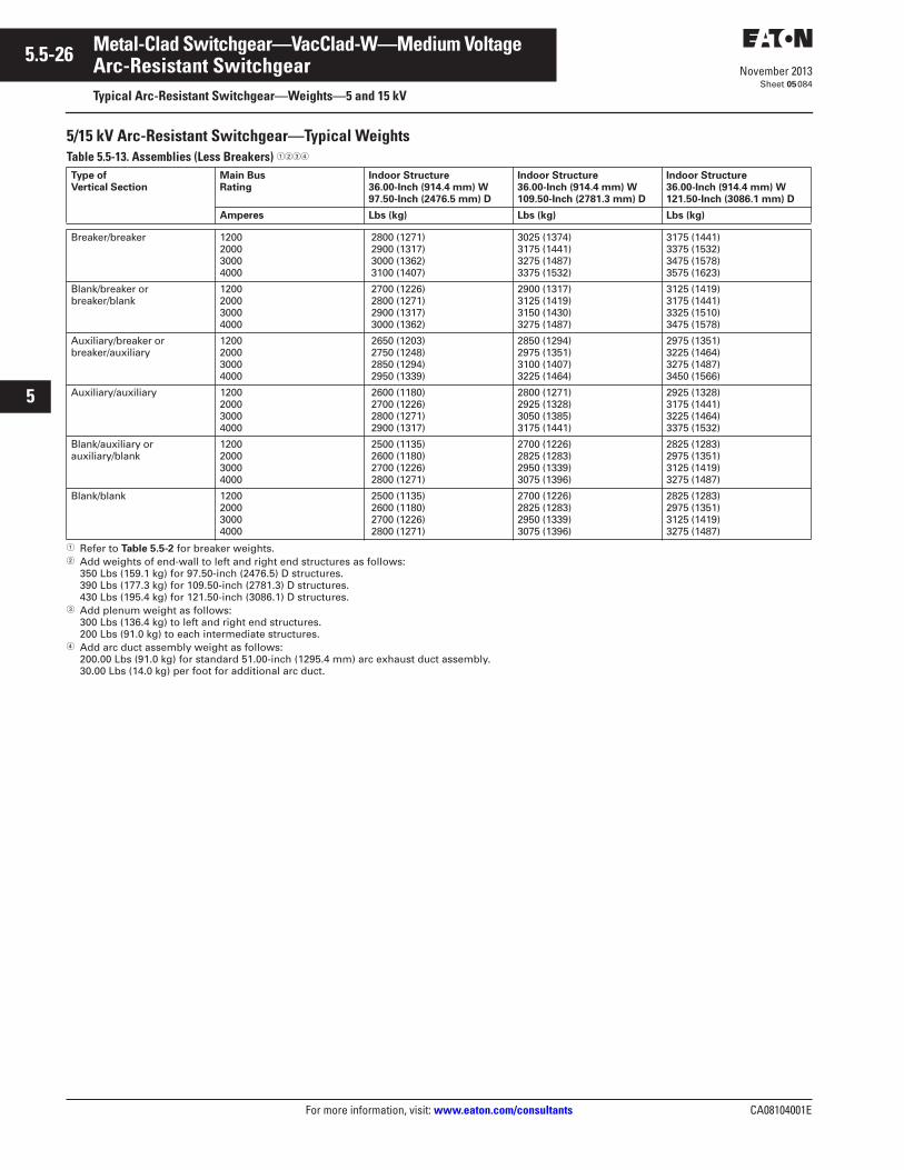
5.5-26
For more information, visit: www.eaton.com/consultants CA08104001E
November 2013
Metal-Clad Switchgear—VacClad-W—Medium Voltage
i
ii
1
2
3
4
5
6
7
8
9
10
11
12
13
14
15
16
17
18
19
20
21
Sheet 05
Arc-Resistant SwitchgearTypical Arc-Resistant Switchgear—Weights—5 and 15 kV
084
5/15 kV Arc-Resistant Switchgear—Typical WeightsTable 5.5-13. Assemblies (Less Breakers) ����
� Refer to Table 5.5-2 for breaker weights.� Add weights of end-wall to left and right end structures as follows:
350 Lbs (159.1 kg) for 97.50-inch (2476.5) D structures.390 Lbs (177.3 kg) for 109.50-inch (2781.3) D structures.430 Lbs (195.4 kg) for 121.50-inch (3086.1) D structures.
� Add plenum weight as follows:300 Lbs (136.4 kg) to left and right end structures.200 Lbs (91.0 kg) to each intermediate structures.
� Add arc duct assembly weight as follows:200.00 Lbs (91.0 kg) for standard 51.00-inch (1295.4 mm) arc exhaust duct assembly.30.00 Lbs (14.0 kg) per foot for additional arc duct.
Type of Vertical Section
Main Bus Rating
Indoor Structure36.00-Inch (914.4 mm) W97.50-Inch (2476.5 mm) D
Indoor Structure36.00-Inch (914.4 mm) W109.50-Inch (2781.3 mm) D
Indoor Structure36.00-Inch (914.4 mm) W121.50-Inch (3086.1 mm) D
Amperes Lbs (kg) Lbs (kg) Lbs (kg)
Breaker/breaker 1200200030004000
2800 (1271) 2900 (1317) 3000 (1362) 3100 (1407)
3025 (1374)3175 (1441)3275 (1487)3375 (1532)
3175 (1441)3375 (1532)3475 (1578)3575 (1623)
Blank/breaker orbreaker/blank
1200200030004000
2700 (1226) 2800 (1271) 2900 (1317) 3000 (1362)
2900 (1317)3125 (1419)3150 (1430)3275 (1487)
3125 (1419)3175 (1441)3325 (1510)3475 (1578)
Auxiliary/breaker orbreaker/auxiliary
1200200030004000
2650 (1203) 2750 (1248) 2850 (1294) 2950 (1339)
2850 (1294)2975 (1351)3100 (1407)3225 (1464)
2975 (1351)3225 (1464)3275 (1487)3450 (1566)
Auxiliary/auxiliary 1200200030004000
2600 (1180) 2700 (1226) 2800 (1271) 2900 (1317)
2800 (1271)2925 (1328)3050 (1385)3175 (1441)
2925 (1328)3175 (1441)3225 (1464)3375 (1532)
Blank/auxiliary orauxiliary/blank
1200200030004000
2500 (1135) 2600 (1180) 2700 (1226) 2800 (1271)
2700 (1226)2825 (1283)2950 (1339)3075 (1396)
2825 (1283)2975 (1351)3125 (1419)3275 (1487)
Blank/blank 1200200030004000
2500 (1135) 2600 (1180) 2700 (1226) 2800 (1271)
2700 (1226)2825 (1283)2950 (1339)3075 (1396)
2825 (1283)2975 (1351)3125 (1419)3275 (1487)
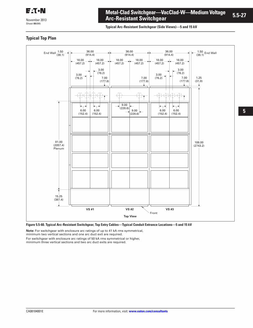
CA08104001E For more information, visit: www.eaton.com/consultants
5.5-27November 2013
Metal-Clad Switchgear—VacClad-W—Medium Voltage
i
ii
1
2
3
4
5
6
7
8
9
10
11
12
13
14
15
16
17
18
19
20
21
Sheet 05
Arc-Resistant SwitchgearTypical Arc-Resistant Switchgear (Side Views)—5 and 15 kV
085
Typical Top Plan
Figure 5.5-60. Typical Arc-Resistant Switchgear, Top Entry Cables—Typical Conduit Entrance Locations—5 and 15 kV
Note: For switchgear with enclosure arc ratings of up to 41 kA rms symmetrical, minimum two vertical sections and one arc duct exit are required.For switchgear with enclosure arc ratings of 50 kA rms symmetrical or higher, minimum three vertical sections and two arc duct exits are required.
36.00(914.4)
18.00(457.2)
18.00(457.2)
36.00(914.4)
36.00(914.4)
1.25(31.8)
18.00(457.2)
18.00(457.2)
18.00(457.2)
18.00(457.2)
7.00(177.8)
6.00(152.4)
9.00(228.6)
3.00(76.2)
1.50(38.1)
81.00(2057.4)Plenum
15.25(387.4)
VS #1 VS #2 VS #3
Top ViewFront
108.00(2743.2)
6.00(152.4)
9.00(228.6)
6.00(152.4)
6.00(152.4)
7.00(177.8)
7.00(177.8)
3.00(76.2)
3.00(76.2)3.00
(76.2)
End Wall 1.50(38.1)
End Wall
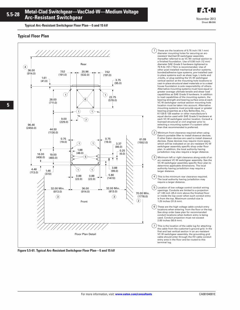
5.5-28
For more information, visit: www.eaton.com/consultants CA08104001E
November 2013
Metal-Clad Switchgear—VacClad-W—Medium Voltage
i
ii
1
2
3
4
5
6
7
8
9
10
11
12
13
14
15
16
17
18
19
20
21
Sheet 05
Arc-Resistant SwitchgearTypical Arc-Resistant Switchgear Floor Plan—5 and 15 kV
086
Typical Floor Plan
Figure 5.5-61. Typical Arc-Resistant Switchgear Floor Plan—5 and 15 kV
Floor Plan Detail
Rear
Front
36.00(914.0)
96.46(2450.0)
1.61(41.0)
7.52(191.0)
20.96(532.0)
7.52(191.0)
22.75(578.0)28.00
(711.0)
44.50(1130.0)
19.00(483.0)
1.46(37.0)
16.00(406.0)
4.46(113.0)
0.75(19.0)
1.88(48.0)
0.88(22.0)
0.88(22.0)
36.00(914.0)
32.00 Min.(813.0)
32.00 Min.(813.0)
0.75(19.0)
3.37(86.0)
0.25(6.0)
3.88(99.0)
5.80(147.0)
61.09(1552.0)
70.00 Min.(1778.0)
3.75(95.0)
9.00(229.0)
6
7
11
11
3 32
4
5
11
1 1
1 These are the locations of 0.75 inch (19.1 mm) diameter mounting holes for securing an arc-resistant VacClad-W switchgear assembly (hereafter referred to as VC-W) vertical section to a finished foundation. Use of 0.50 inch (12 mm) diameter SAE Grade 5 hardware tightened to 75 ft-lb (101.7 Nm) is recommended. Use of other post-installed mechanical anchor systems, bonded/adhesive type systems, pre-installed cast-in-place systems such as shear lugs, L-bolts and J-bolts, or plug welding the VC-W switchgear vertical section at the mounting hole locations to cast-in-place structural steel materials or to a steel house foundation is sole responsibility of others. Alternative mounting systems must have equal or greater average ultimate tensile and shear load capabilities as SAE Grade 5 hardware. In addition to load capabilities of the mounting system, the bearing strength and bearing surface area at each VC-W switchgear vertical section mounting hole location must be taken into account. Alternative mounting systems must provide equal or greater bearing properties as a Key Bellevilles, Inc., K1125-E-125 washer or other manufacturer’s equal device used with SAE Grade 5 hardware at each VC-W switchgear anchor location. Consult a licensed structural or civil engineer prior to selecting a mounting system if a system other than that recommended is preferred.
2 Minimum front clearance required when using Eaton’s portable lifter to install drawout devices. If other Eaton devices are used to install drawout devices, these devices may require more space, which will be indicated on an arc-resistant VC-W switchgear assembly specific shop order floor plan. In addition, the local authority having jurisdiction may also require a larger distance.
3 Minimum left or right clearance along ends of an arc-resistant VC-W switchgear assembly. See the VC-W switchgear assembly specific floor plan to determine applicable dimensions. The local authority having jurisdiction may require a larger distance.
4 This is the minimum rear clearance required. The local authority having jurisdiction may require a larger distance.
5 Location of low voltage control conduit wiring openings. Conduits are limited to a projection of 1.00 inch (25.4 mm) above the finished floor or inside the top cover when such conduit entry is from the top. Maximum conduit size is 1.25 inches (31.8 mm).
6 These are the high voltage cable conduit entry locations when entering from the floor or the top. See shop order base plan for recommended conduit locations when bottom entry is being used. Conduit projection must not exceed 2.00 inches (50.8 mm).
7 This is the location of the cable lug for attaching the cable from the customer’s ground grid. In the first and last vertical section in an arc-resistant VC-W switchgear assembly, the grounding grid cable should enter through the HV cable conduit entry area in the floor and be routed to this terminal lug.
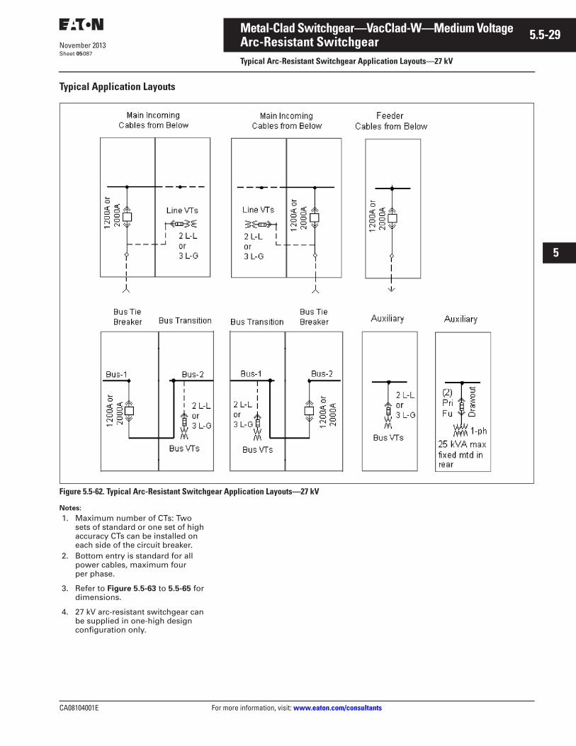
CA08104001E For more information, visit: www.eaton.com/consultants
5.5-29November 2013
Metal-Clad Switchgear—VacClad-W—Medium Voltage
i
ii
1
2
3
4
5
6
7
8
9
10
11
12
13
14
15
16
17
18
19
20
21
Sheet 05
Arc-Resistant SwitchgearTypical Arc-Resistant Switchgear Application Layouts—27 kV
087
Typical Application Layouts
Figure 5.5-62. Typical Arc-Resistant Switchgear Application Layouts—27 kV
Notes:
1. Maximum number of CTs: Two sets of standard or one set of high accuracy CTs can be installed on each side of the circuit breaker.
2. Bottom entry is standard for all power cables, maximum four per phase.
3. Refer to Figure 5.5-63 to 5.5-65 for dimensions.
4. 27 kV arc-resistant switchgear can be supplied in one-high design configuration only.
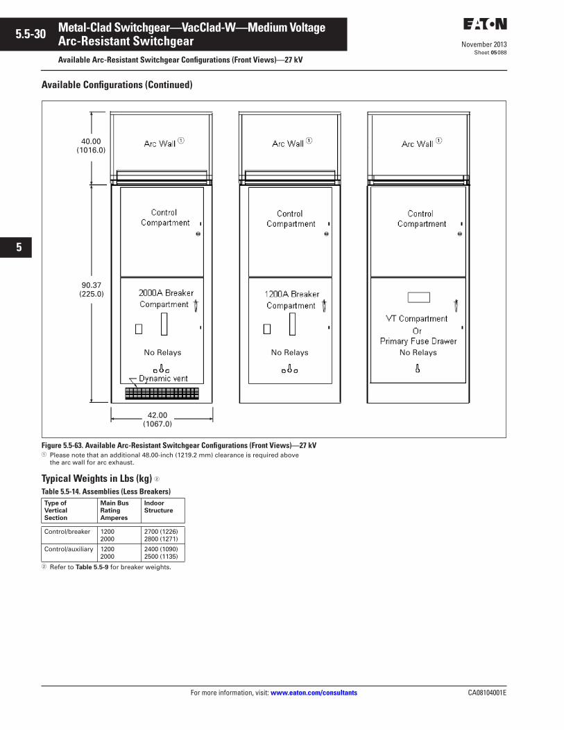
5.5-30
For more information, visit: www.eaton.com/consultants CA08104001E
November 2013
Metal-Clad Switchgear—VacClad-W—Medium Voltage
i
ii
1
2
3
4
5
6
7
8
9
10
11
12
13
14
15
16
17
18
19
20
21
Sheet 05
Arc-Resistant SwitchgearAvailable Arc-Resistant Switchgear Configurations (Front Views)—27 kV
088
Available Configurations (Continued)
Figure 5.5-63. Available Arc-Resistant Switchgear Configurations (Front Views)—27 kV� Please note that an additional 48.00-inch (1219.2 mm) clearance is required above
the arc wall for arc exhaust.
Typical Weights in Lbs (kg) �
Table 5.5-14. Assemblies (Less Breakers)
� Refer to Table 5.5-9 for breaker weights.
No Relays No Relays No Relays
40.00(1016.0)
90.37(225.0)
42.00(1067.0)
Type ofVerticalSection
Main BusRatingAmperes
IndoorStructure
Control/breaker 12002000
2700 (1226)2800 (1271)
Control/auxiliary 12002000
2400 (1090)2500 (1135)
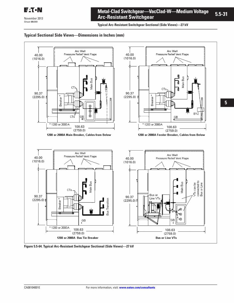
CA08104001E For more information, visit: www.eaton.com/consultants
5.5-31November 2013
Metal-Clad Switchgear—VacClad-W—Medium Voltage
i
ii
1
2
3
4
5
6
7
8
9
10
11
12
13
14
15
16
17
18
19
20
21
Sheet 05
Arc-Resistant SwitchgearTypical Arc-Resistant Switchgear Sectional (Side Views)—27 kV
089
Typical Sectional Side Views—Dimensions in Inches (mm)
Figure 5.5-64. Typical Arc-Resistant Switchgear Sectional (Side Views)—27 kV
40.00(1016.0)
90.37(2295.0)
40.00(1016.0)
90.37(2295.0)
40.00(1016.0)
90.37(2295.0)
40.00(1016.0)
90.37(2295.0)
108.63(2759.0)
108.63(2759.0)
108.63(2759.0)
108.63(2759.0)
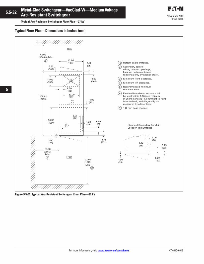
5.5-32
For more information, visit: www.eaton.com/consultants CA08104001E
November 2013
Metal-Clad Switchgear—VacClad-W—Medium Voltage
i
ii
1
2
3
4
5
6
7
8
9
10
11
12
13
14
15
16
17
18
19
20
21
Sheet 05
Arc-Resistant SwitchgearTypical Arc-Resistant Switchgear Floor Plan—27 kV
090
Typical Floor Plan—Dimensions in Inches (mm)
Figure 5.5-65. Typical Arc-Resistant Switchgear Floor Plan—27 kV
2
3
4
5
6
50.38 (1280)
1.00 (25)
38.00 (965.2) Min.
472.00 (1829) Min.
Front
3
2
14.00 (356)
6.00 (152)
42.00 (1066.8) Min.
5.50 (140)
5
4.00 (102)
42.00 (1067)
30.00 (762)
7
1B
Rear
1.00 (25)
4.00 (102)
6.00 (152)
3.00 (76)
1.38 (35)
108.62 (2759)
4.75 (121)
1.00 (25)
6.00 (152)
3.25 (83)
3.00 (76)
1.12 (29)
Bottom cable entrance.
Secondary control wiring conduit openings, location bottom entrance(optional; only by special order).
Minimum front clearance.
Minimum left clearance.
Recommended minimum rear clearance.
Finished foundation surface shall be level within 0.06-inch (1.5 mm) in 36.00 inches (914.4 mm) left-to-right, front-to-back, and diagonally, as measured by a laser level.
102 mm base channel. 7
Standard Secondary Conduit Location Top Entrance
1B
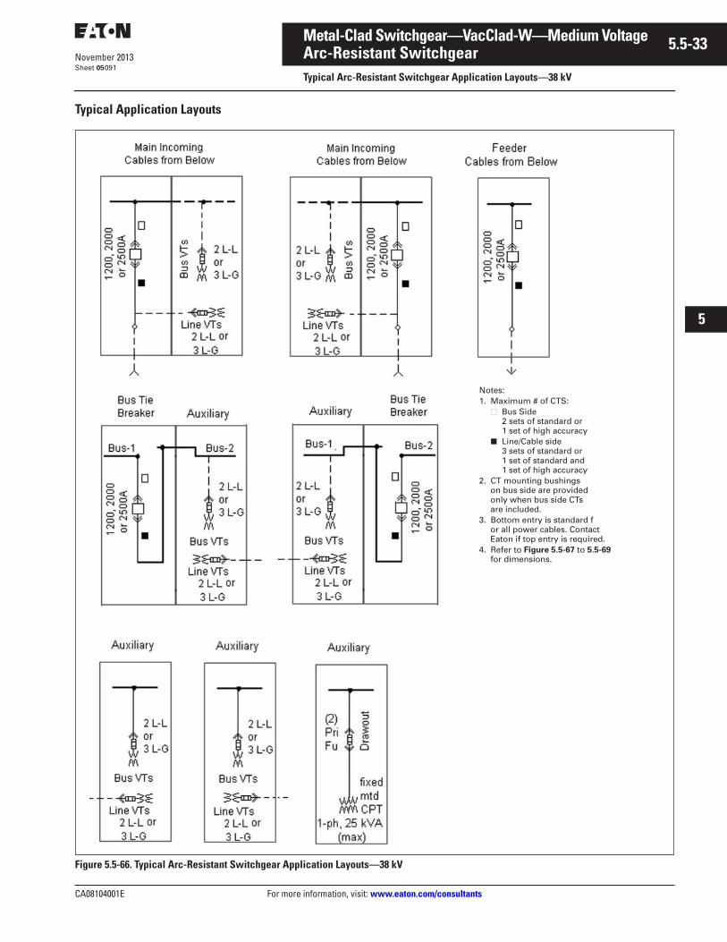
CA08104001E For more information, visit: www.eaton.com/consultants
5.5-33November 2013
Metal-Clad Switchgear—VacClad-W—Medium Voltage
i
ii
1
2
3
4
5
6
7
8
9
10
11
12
13
14
15
16
17
18
19
20
21
Sheet 05
Arc-Resistant SwitchgearTypical Arc-Resistant Switchgear Application Layouts—38 kV
091
Typical Application Layouts
Figure 5.5-66. Typical Arc-Resistant Switchgear Application Layouts—38 kV
Notes:1. Maximum # of CTS:
■ Bus Side2 sets of standard or 1 set of high accuracy
■ Line/Cable side3 sets of standard or 1 set of standard and 1 set of high accuracy
2. CT mounting bushings on bus side are provided only when bus side CTs are included.
3. Bottom entry is standard for all power cables. ContactEaton if top entry is required.
4. Refer to Figure 5.5-67 to 5.5-69for dimensions.
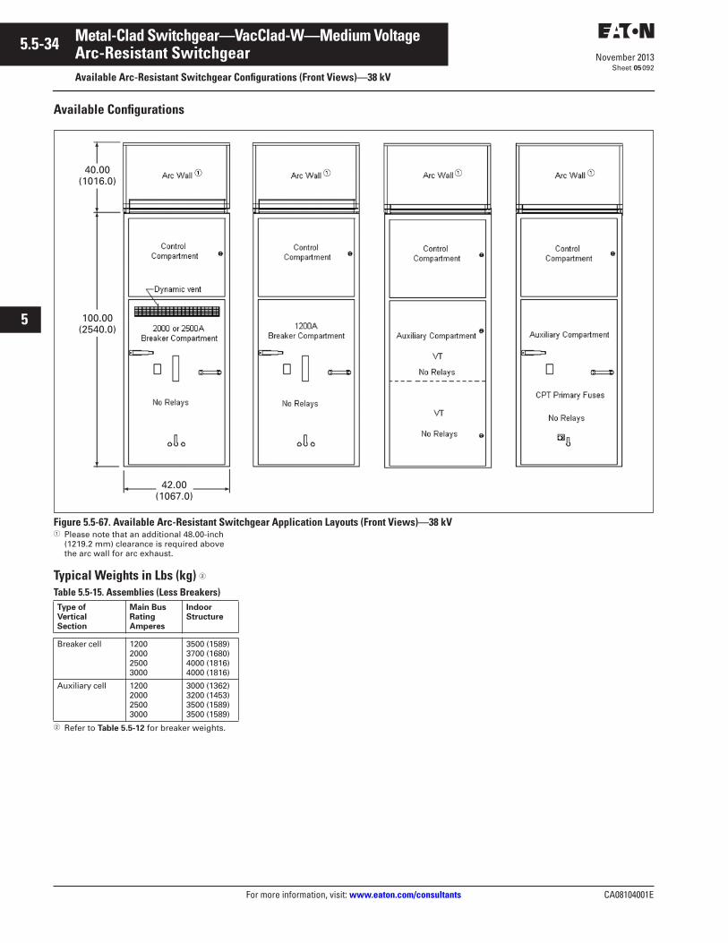
5.5-34
For more information, visit: www.eaton.com/consultants CA08104001E
November 2013
Metal-Clad Switchgear—VacClad-W—Medium Voltage
i
ii
1
2
3
4
5
6
7
8
9
10
11
12
13
14
15
16
17
18
19
20
21
Sheet 05
Arc-Resistant SwitchgearAvailable Arc-Resistant Switchgear Configurations (Front Views)—38 kV
092
Available Configurations
Figure 5.5-67. Available Arc-Resistant Switchgear Application Layouts (Front Views)—38 kV� Please note that an additional 48.00-inch
(1219.2 mm) clearance is required above the arc wall for arc exhaust.
Typical Weights in Lbs (kg) �
Table 5.5-15. Assemblies (Less Breakers)
� Refer to Table 5.5-12 for breaker weights.
40.00(1016.0)
100.00(2540.0)
42.00(1067.0)
Type ofVerticalSection
Main BusRatingAmperes
IndoorStructure
Breaker cell 1200200025003000
3500 (1589)3700 (1680)4000 (1816)4000 (1816)
Auxiliary cell 1200200025003000
3000 (1362)3200 (1453)3500 (1589)3500 (1589)
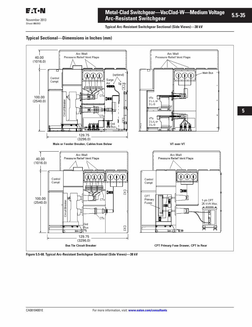
CA08104001E For more information, visit: www.eaton.com/consultants
5.5-35November 2013
Metal-Clad Switchgear—VacClad-W—Medium Voltage
i
ii
1
2
3
4
5
6
7
8
9
10
11
12
13
14
15
16
17
18
19
20
21
Sheet 05
Arc-Resistant SwitchgearTypical Arc-Resistant Switchgear Sectional (Side Views)—38 kV
093
Typical Sectional—Dimensions in Inches (mm)
Figure 5.5-68. Typical Arc-Resistant Switchgear Sectional (Side Views)—38 kV
40.00(1016.0)
100.00(2540.0)
129.75(3296.0)
40.00(1016.0)
100.00(2540.0)
129.75(3296.0)
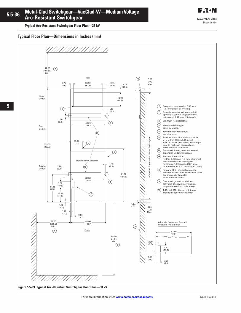
5.5-36
For more information, visit: www.eaton.com/consultants CA08104001E
November 2013
Metal-Clad Switchgear—VacClad-W—Medium Voltage
i
ii
1
2
3
4
5
6
7
8
9
10
11
12
13
14
15
16
17
18
19
20
21
Sheet 05
Arc-Resistant SwitchgearTypical Arc-Resistant Switchgear Floor Plan—38 kV
094
Typical Floor Plan—Dimensions in Inches (mm)
Figure 5.5-69. Typical Arc-Resistant Switchgear Floor Plan—38 kV
Alternate Secondary ConduitLocation Top Entrance
2
3
Front
Rear
4
Suggested locations for 0.50-Inch(12.7 mm) bolts or welding.
Secondary control wiring conduit openings, conduit projection must not exceed 1.00 inch (25.4 mm).
Minimum front clearance.
Minimum left-hinged panel clearance.
Recommended minimumrear clearance.
Finished foundation surface shall be level within 0.06-inch (1.5 mm) in 36.00 inches (914.4 mm) left-to-right, front-to-back, and diagonally, as measured by a laser level.Floor steel if used, must not exceeddimension under switchgear.
Primary (H.V.) conduit projection must not exceed 2.00 inches (50.8 mm). See shop order base planfor conduit locations.
Customer’s ground provisions,provided as shown by symbol onshop order sectional side views.
5
6
7A
7B
8
9
5
7B
7B
6
3
LineCompt
BusCompt
BreakerCompt
4.00-inch (101.6 mm) minimum channel supplied by customer.
3.00(7.6)Max.
Finished foundation(within 0.06-inch [1.5 mm] clearance) must extend under switchgearminimum 1.50 inches (38.1 mm)to a maximum 3.00 inches (76.2 mm).
Un
fin
ish
ed F
ou
nd
atio
n U
nd
er S
wit
chg
ear
38.00(965.2)Min.
42.00(106.7)
1.50(38.1)
129.75(329.5)
1.70(43.2)
3.00(76.2)
16.38[41.6]
7.50(19.0)
4
84.00(213.4)Min.
7A
1.16(2.9)
61.62(156.5)
14.63(37.2) 9
31.88(81.0)
10
10
Supplied by Customer
1
2
34.50(87.6)
3.75(9.5)
3.75(9.5) 4.15
(10.5)
16.00(40.6)
3.00(7.6)
7.50(19.1)
3.38(8.6)
2.20(5.6)
42.00(106.7)
2.00(5.1)
39.58(100.5)
42.00(1066.8)
Min.
1
2.00(5.1)
.88(22.3)
8
40.24(102.2)
3.00(7.6)Max.
1
10
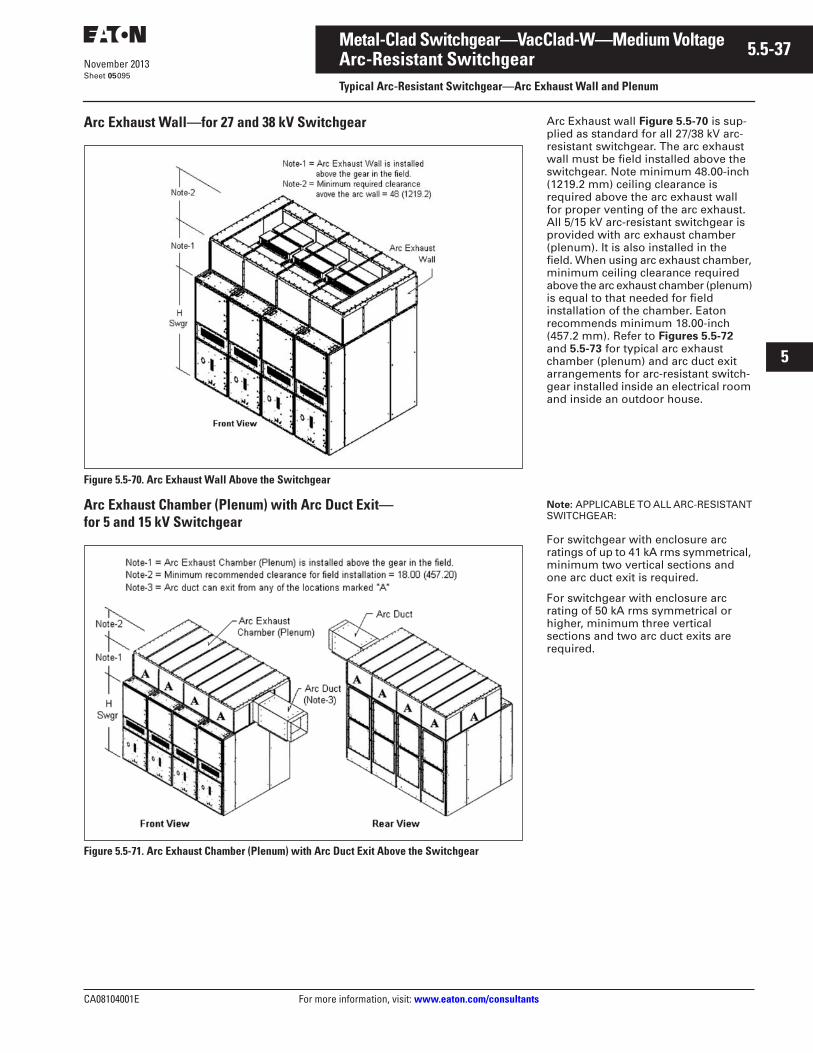
CA08104001E For more information, visit: www.eaton.com/consultants
5.5-37November 2013
Metal-Clad Switchgear—VacClad-W—Medium Voltage
i
ii
1
2
3
4
5
6
7
8
9
10
11
12
13
14
15
16
17
18
19
20
21
Sheet 05
Arc-Resistant SwitchgearTypical Arc-Resistant Switchgear—Arc Exhaust Wall and Plenum
095
Arc Exhaust Wall—for 27 and 38 kV Switchgear
Figure 5.5-70. Arc Exhaust Wall Above the Switchgear
Arc Exhaust Chamber (Plenum) with Arc Duct Exit—for 5 and 15 kV Switchgear
Figure 5.5-71. Arc Exhaust Chamber (Plenum) with Arc Duct Exit Above the Switchgear
Arc Exhaust wall Figure 5.5-70 is sup-plied as standard for all 27/38 kV arc-resistant switchgear. The arc exhaust wall must be field installed above the switchgear. Note minimum 48.00-inch (1219.2 mm) ceiling clearance is required above the arc exhaust wall for proper venting of the arc exhaust. All 5/15 kV arc-resistant switchgear is provided with arc exhaust chamber (plenum). It is also installed in the field. When using arc exhaust chamber, minimum ceiling clearance required above the arc exhaust chamber (plenum) is equal to that needed for field installation of the chamber. Eaton recommends minimum 18.00-inch (457.2 mm). Refer to Figures 5.5-72 and 5.5-73 for typical arc exhaust chamber (plenum) and arc duct exit arrangements for arc-resistant switch-gear installed inside an electrical room and inside an outdoor house.
Note: APPLICABLE TO ALL ARC-RESISTANT SWITCHGEAR:
For switchgear with enclosure arc ratings of up to 41 kA rms symmetrical, minimum two vertical sections and one arc duct exit is required.
For switchgear with enclosure arc rating of 50 kA rms symmetrical or higher, minimum three vertical sections and two arc duct exits are required.
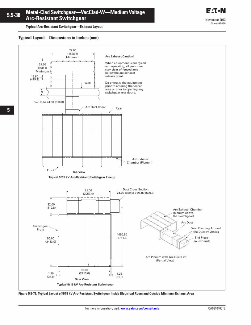
5.5-38
For more information, visit: www.eaton.com/consultants CA08104001E
November 2013
Metal-Clad Switchgear—VacClad-W—Medium Voltage
i
ii
1
2
3
4
5
6
7
8
9
10
11
12
13
14
15
16
17
18
19
20
21
Sheet 05
Arc-Resistant SwitchgearTypical Arc-Resistant Switchgear—Exhaust Layout
096
Typical Layout—Dimensions in Inches (mm)
Figure 5.5-72. Typical Layout of 5/15 kV Arc-Resistant Switchgear Inside Electrical Room and Outside Minimum Exhaust Area
81.00(2057.4)
32.00(812.8)
95.00(2413.0)
SwitchgearFront
1.25(31.8)
1.25(31.8)
95.00(2413.0)
Side View
Typical 5/15 kV Arc-Resistant Switchgear
1090.50(2781.3)
Arc ExhaustChamber (Plenum)
FrontTop View
Typical 5/15 kV Arc-Resistant Switchgear Lineup
End Piece(arc exhaust)
Arc Duct
Arc Exhaust Chamber(plenum above the switchgear)
Arc Plenum with Arc Duct Exit(Partial View)
Wall Flashing Aroundthe Duct by Others
Duct Cross Section24.00 (609.6) x 24.00 (609.6)
72.00(1828.8)
Minimum
Wall
= Up to 24.00 (610.0)
Arc Exhaust Caution!
When equipment is energized and operating, all personnel stay clear of fenced area below the arc exhaust release point.
De-energize the equipment prior to entering the fenced area or prior to opening any switchgear rear doors.
31.50(800.1)
Minimum
Arc Duct Collar Rear
16.50(419.1)
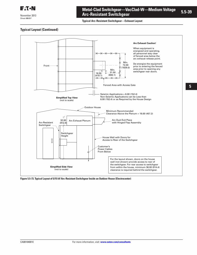
CA08104001E For more information, visit: www.eaton.com/consultants
5.5-39November 2013
Metal-Clad Switchgear—VacClad-W—Medium Voltage
i
ii
1
2
3
4
5
6
7
8
9
10
11
12
13
14
15
16
17
18
19
20
21
Sheet 05
Arc-Resistant SwitchgearTypical Arc-Resistant Switchgear—Exhaust Layout
097
Typical Layout (Continued)
Figure 5.5-73. Typical Layout of 5/15 kV Arc-Resistant Switchgear Inside an Outdoor House (Electrocenter)
Arc Exhaust Caution!
When equipment is energized and operating, all personnel stay clear of fenced area below the arc exhaust release point.
De-energize the equipment prior to entering the fenced area prior to opening any switchgear rear doors.
Minimum RecommendedClearance Above the Plenum = 18.00 (457.2)
Arc Duct Exit Piece with Hinged Flap Assembly
Customer’s Power Cables From Below
Simplified Side View(not to scale)
SwitchgearHeight
Arc-Resistant Switchgear
Arc Exhaust Plenum32.00(812.8)
Outdoor House
Front
Simplified Top View(not to scale)
Fenced Area with Access Gate
Min.72.00
(1829.0)Min.31.50
(800.1)
Seismic Applications = 6.00 (152.4)Non-Seismic Applications can be Less than6.00 (152.4) or as Required by the House Design
House Wall with Doors forAccess to Rear of the Switchgear
For the layout shown, doors on the house wall (not shown) provide access to rear of the switchgear. For rear access to switchgear from within the house, minimum 36.00 (914.4) clearance is required behind the switchgear.
16.50(419.1)

5.5-40
For more information, visit: www.eaton.com/consultants CA08104001E
November 2013
Metal-Clad Switchgear—VacClad-W—Medium Voltage
i
ii
1
2
3
4
5
6
7
8
9
10
11
12
13
14
15
16
17
18
19
20
21
Sheet 05098
This page intentionally left blank.
Related Documents