T S R Compliance Inject Anti-Foam Chemicals into the 242-A Vapor/Liquid Separator C-A-1 Type REFERENCE Document No. TO-660-141 Rev/Mod K-9 Release Date 10/29/2018 Page 1 of 27 Tank Farm Plant Operating Procedure 242-A Evaporator USQ # EV-18-0485, Rev. 1 CHANGE HISTORY ( LAST 5 REV-MODS ) Rev-Mod Release Date Justification: Summary of Changes K-9 10/29/2018 Operations Request Added new section "system flush" Moved previous system flush to new section "anti-foam line flush" Added new Step : ENSURE valves 5-37 and 5-42 are CLOSED. K-8 07/12/2018 Operations Request Under Page 21 after "After boil-off established: 0.2" level drop per hour (0.6" drop for three hours)", add the following as a separate line (and underline): "OR as stated per Process Memo". K-7 03/28/2018 Operations Request Changing the time (from two hours to three hours) on both Sec. 5.3.9 and 5.4.12 to match with its Data Sheet 2 time. K-6 12/19/2017 WRPS-PER-2017-1808 Changed Attachment 2 to Data Sheet 2 and put in required initial columns for NCO and SM/OE. Added a signature sheet. Updated RECORDS section. K-5 10/11/2017 Operations Request Modified Attachment 2 - recording anti-foam tank level readings from 1 hour to three hours also during startup (6” drop for three hours) and after boil off established (0.6” drop for three hours) Table of Contents Page 1.0 PURPOSE AND SCOPE ................................................................................................................ 3 1.1 Purpose................................................................................................................................ 3 1.2 Scope ................................................................................................................................... 3 2.0 INFORMATION............................................................................................................................. 4 2.1 General Information ............................................................................................................ 4 3.0 PRECAUTIONS AND LIMITATIONS......................................................................................... 5 3.1 Personnel Safety.................................................................................................................. 5 3.2 Limits .................................................................................................................................. 5 4.0 PREREQUISITES .......................................................................................................................... 6 4.1 Special Tools, Equipment and Supplies.............................................................................. 6 4.2 Field Preparation ................................................................................................................. 6 5.0 PROCEDURE ................................................................................................................................. 7 5.1 Initial Pre-dilute and Mix Anti-Foam Chemical ................................................................. 7 5.2 Dilute and Mix Anti-Foam Chemical During Injection Into C-A-1 Vessel ..................... 11

Welcome message from author
This document is posted to help you gain knowledge. Please leave a comment to let me know what you think about it! Share it to your friends and learn new things together.
Transcript

T S R Compliance
Inject Anti-Foam Chemicals into the 242-A Vapor/Liquid Separator C-A-1
Type
REFERENCE Document No.
TO-660-141 Rev/Mod
K-9 Release Date
10/29/2018 Page
1 of 27
Tank Farm Plant Operating Procedure 242-A Evaporator
USQ # EV-18-0485, Rev. 1
CHANGE HISTORY ( LAST 5 REV-MODS )
Rev-Mod Release Date Justification: Summary of Changes
K-9 10/29/2018 Operations Request
Added new section "system flush"
Moved previous system flush to new section "anti-foam line
flush" Added new Step : ENSURE valves 5-37 and 5-42 are
CLOSED.
K-8 07/12/2018 Operations Request
Under Page 21 after "After boil-off established: 0.2" level drop
per hour (0.6" drop for three hours)", add the following as a
separate line (and underline): "OR as stated per Process Memo".
K-7 03/28/2018 Operations Request Changing the time (from two hours to three hours) on both Sec.
5.3.9 and 5.4.12 to match with its Data Sheet 2 time.
K-6 12/19/2017 WRPS-PER-2017-1808
Changed Attachment 2 to Data Sheet 2 and put in required
initial columns for NCO and SM/OE. Added a signature sheet.
Updated RECORDS section.
K-5 10/11/2017 Operations Request
Modified Attachment 2 - recording anti-foam tank level readings
from 1 hour to three hours
also during startup (6” drop for three hours) and after boil off
established (0.6” drop for three hours)
Table of Contents Page
1.0 PURPOSE AND SCOPE ................................................................................................................ 3
1.1 Purpose ................................................................................................................................ 3
1.2 Scope ................................................................................................................................... 3
2.0 INFORMATION............................................................................................................................. 4
2.1 General Information ............................................................................................................ 4
3.0 PRECAUTIONS AND LIMITATIONS......................................................................................... 5
3.1 Personnel Safety.................................................................................................................. 5
3.2 Limits .................................................................................................................................. 5
4.0 PREREQUISITES .......................................................................................................................... 6
4.1 Special Tools, Equipment and Supplies.............................................................................. 6
4.2 Field Preparation ................................................................................................................. 6
5.0 PROCEDURE ................................................................................................................................. 7
5.1 Initial Pre-dilute and Mix Anti-Foam Chemical ................................................................. 7
5.2 Dilute and Mix Anti-Foam Chemical During Injection Into C-A-1 Vessel ..................... 11

T S R Compliance
Inject Anti-Foam Chemicals into the 242-A Vapor/Liquid Separator C-A-1
Type
REFERENCE Document No.
TO-660-141 Rev/Mod
K-9 Release Date
10/29/2018 Page
2 of 27
5.3 Inject Anti-Foam Emulsion Into C-A-1 Vessel ................................................................ 13
5.4 Shut Down and Flush Anti-Foam Chemical Injection System ......................................... 15
5.5 System Flush ..................................................................................................................... 18
5.6 Anti-Foam line Flush ........................................................................................................ 20
5.7 Records ............................................................................................................................. 21
Data Sheet 1 – Anti-Foam Makeup .......................................................................................................... 22
Data Sheet 2 - TK-E-102 dropout rate ROUND SHEET ......................................................................... 23
Attachment 1 – TK-E-102 Conversion Table ........................................................................................... 24
Signature Sheet 1 ...................................................................................................................................... 25
Figure 1 - Anti-Foam Chemical Injection System .................................................................................... 26
Figure 2 - TK-E-102 Control Panel .......................................................................................................... 27

T S R Compliance
Inject Anti-Foam Chemicals into the 242-A Vapor/Liquid Separator C-A-1
Type
REFERENCE Document No.
TO-660-141 Rev/Mod
K-9 Release Date
10/29/2018 Page
3 of 27
1.0 PURPOSE AND SCOPE
1.1 Purpose
This procedure provides instructions for mixing and adding Anti-Foam Chemicals to the
Evaporator Vessel C-A-1.
1.2 Scope
This procedure applies to the 242-A Anti-Foam Tank TK-E-102, the Anti-Foam injection
pump P-E-102, Agitator A-E-102, and their associated instrumentation and controls.
T S R Compliance
Inject Anti-Foam Chemicals into the 242-A Vapor/Liquid Separator C-A-1
Type
REFERENCE Document No.
TO-660-141 Rev/Mod
K-9 Release Date
10/29/2018 Page
4 of 27
2.0 INFORMATION
2.1 General Information
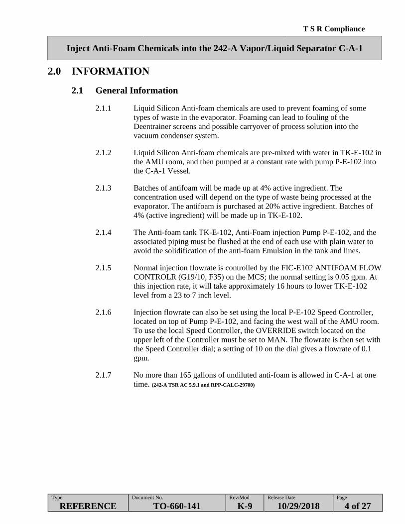
2.1.1 Liquid Silicon Anti-foam chemicals are used to prevent foaming of some
types of waste in the evaporator. Foaming can lead to fouling of the
Deentrainer screens and possible carryover of process solution into the
vacuum condenser system.
2.1.2 Liquid Silicon Anti-foam chemicals are pre-mixed with water in TK-E-102 in
the AMU room, and then pumped at a constant rate with pump P-E-102 into
the C-A-1 Vessel.
2.1.3 Batches of antifoam will be made up at 4% active ingredient. The
concentration used will depend on the type of waste being processed at the
evaporator. The antifoam is purchased at 20% active ingredient. Batches of
4% (active ingredient) will be made up in TK-E-102.
2.1.4 The Anti-foam tank TK-E-102, Anti-Foam injection Pump P-E-102, and the
associated piping must be flushed at the end of each use with plain water to
avoid the solidification of the anti-foam Emulsion in the tank and lines.
2.1.5 Normal injection flowrate is controlled by the FIC-E102 ANTIFOAM FLOW
CONTROLR (G19/10, F35) on the MCS; the normal setting is 0.05 gpm. At
this injection rate, it will take approximately 16 hours to lower TK-E-102
level from a 23 to 7 inch level.
2.1.6 Injection flowrate can also be set using the local P-E-102 Speed Controller,
located on top of Pump P-E-102, and facing the west wall of the AMU room.
To use the local Speed Controller, the OVERRIDE switch located on the
upper left of the Controller must be set to MAN. The flowrate is then set with
the Speed Controller dial; a setting of 10 on the dial gives a flowrate of 0.1
gpm.
2.1.7 No more than 165 gallons of undiluted anti-foam is allowed in C-A-1 at one
time. (242-A TSR AC 5.9.1 and RPP-CALC-29700)

T S R Compliance
Inject Anti-Foam Chemicals into the 242-A Vapor/Liquid Separator C-A-1
Type
REFERENCE Document No.
TO-660-141 Rev/Mod
K-9 Release Date
10/29/2018 Page
5 of 27
3.0 PRECAUTIONS AND LIMITATIONS
3.1 Personnel Safety
WARNING - Failure to wear appropriate protective gear during chemical transfer could
result in skin or eye irritation from uncontrolled exposure to the
Anti-Foam Emulsion.
3.1.1 Care should be taken to avoid eye or skin contact with the anti-foam
Emulsion, which can produce irritation. If the chemical does come into
contact with eyes or skin, flush the area with fresh water. A permanent or
portable eye wash station must be available to perform this procedure.
3.1.2 Safety Glasses and rubber gloves must be worn when working with the
anti-foam Emulsion. After working with the chemical, wash thoroughly with
soap and warm water before eating or drinking.
3.1.3 The anti-foam chemical is Liquid Silicon Antifoam Emulsion. See the GHS-
SDS and/or MSDS information sheet #12961A.
3.2 Limits
HNF-15279 242-A EVAPORATOR TECHNICAL SAFETY REQUIREMENTS
242-A TSR AC 5.9.1 - C-A-1 Vessel Time to Lower Flammability Limit
(AC Key Element)

T S R Compliance
Inject Anti-Foam Chemicals into the 242-A Vapor/Liquid Separator C-A-1
Type
REFERENCE Document No.
TO-660-141 Rev/Mod
K-9 Release Date
10/29/2018 Page
6 of 27
4.0 PREREQUISITES
4.1 Special Tools, Equipment and Supplies
One drum of Dow-Corning 1520-US Silicone Antifoam
Drum pump
Rubber gloves
Safety glasses
Drum wrench.
4.2 Field Preparation
The following conditions must be met before any of the following Sections may
commence:
4.2.1 PRIOR to performing Section 5.1, ENSURE Supervisor direction to prepare
Initial Anti-Foam chemical for addition to the C-A-1 Vessel has been
received.
4.2.2 PRIOR to performing Section 5.2, ENSURE the following:
Anti-Foam system operating
Supervision direction to prepare Anti-Foam chemical and continue
Anti-Foam chemical injection to the C-A-1 Vessel.
4.2.3 PRIOR to performing Section 5.3, ENSURE Supervisor direction to inject
Anti-Foam chemical to the C-A-1 Vessel has been received.
4.2.4 PRIOR to performing Section 5.4, ENSURE Supervisor direction to shut
down and flush the Anti-Foam system has been received.
T S R Compliance
Inject Anti-Foam Chemicals into the 242-A Vapor/Liquid Separator C-A-1
Type
REFERENCE Document No.
TO-660-141 Rev/Mod
K-9 Release Date
10/29/2018 Page
7 of 27
5.0 PROCEDURE
NOTE - Sections 5.1 through 5.6 can be performed in any order and at any time, per shift
manager direction.
This procedure may be used to operate the anti-foam system with water only for
training and testing.
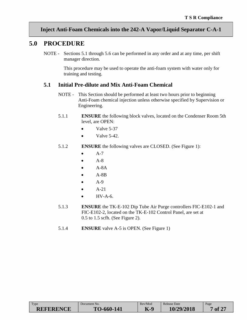
5.1 Initial Pre-dilute and Mix Anti-Foam Chemical
NOTE - This Section should be performed at least two hours prior to beginning
Anti-Foam chemical injection unless otherwise specified by Supervision or
Engineering.
5.1.1 ENSURE the following block valves, located on the Condenser Room 5th
level, are OPEN:
Valve 5-37
Valve 5-42.
5.1.2 ENSURE the following valves are CLOSED. (See Figure 1):
A-7
A-8
A-8A
A-8B
A-9
A-21
HV-A-6.
5.1.3 ENSURE the TK-E-102 Dip Tube Air Purge controllers FIC-E102-1 and
FIC-E102-2, located on the TK-E-102 Control Panel, are set at
0.5 to 1.5 scfh. (See Figure 2).
5.1.4 ENSURE valve A-5 is OPEN. (See Figure 1)

T S R Compliance
Inject Anti-Foam Chemicals into the 242-A Vapor/Liquid Separator C-A-1
Type
REFERENCE Document No.
TO-660-141 Rev/Mod
K-9 Release Date
10/29/2018 Page
8 of 27
5.1 Initial Pre-dilute and Mix Anti-Foam Chemical (Cont.)
5.1.5 IF reading on local weight factor indicator WFI-E102-2, located on the
TK-E-102 instrument panel (see Figure 2) or on WFI-E102 ANTIFOAM
TANK WT FACTOR (G19, F35).is greater than 0 inches, DRAIN TK-E-102
as follows:
5.1.5.1 OPEN TK-E-102 drain valve A-9.
5.1.5.2 WAIT until flow through the drain line stops.
5.1.5.3 CLOSE valve A-9.
5.1.6 RECORD the following on Data Sheet 1 on initial fill:
Date
Time
Initial fill
% active ingredient of anti-foam to be made up per Process Memo /
Supervision
Current TK-E-102 tank level from WFI-E102-2.
NOTE - If the facility is in operation on filtered raw water for seal water, opening valve
A-8 abruptly can cause a loss-of-seal-water condition for PB1 and PB2.
5.1.7 SLOWLY OPEN the following Filtered Raw Water valves to begin adding
filtered raw water to TK-E-102.
A-8
A-8B.
5.1.8 WHEN WFI-E102-2 reads 19” WF, SLOWLY CLOSE the following
valves to stop filtered raw water flow:
A-8
A-8B.
T S R Compliance
Inject Anti-Foam Chemicals into the 242-A Vapor/Liquid Separator C-A-1
Type
REFERENCE Document No.
TO-660-141 Rev/Mod
K-9 Release Date
10/29/2018 Page
9 of 27
5.1 Initial Pre-dilute and Mix Anti-Foam Chemical (Cont.)
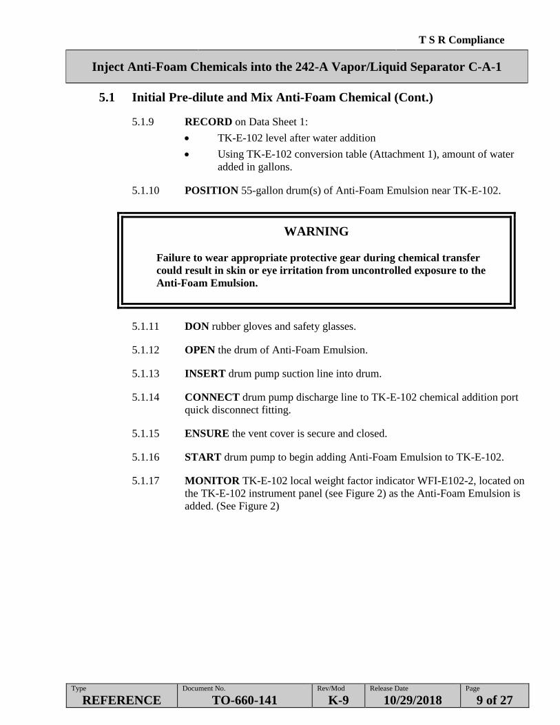
5.1.9 RECORD on Data Sheet 1:
TK-E-102 level after water addition
Using TK-E-102 conversion table (Attachment 1), amount of water
added in gallons.
5.1.10 POSITION 55-gallon drum(s) of Anti-Foam Emulsion near TK-E-102.
WARNING
Failure to wear appropriate protective gear during chemical transfer
could result in skin or eye irritation from uncontrolled exposure to the
Anti-Foam Emulsion.
5.1.11 DON rubber gloves and safety glasses.
5.1.12 OPEN the drum of Anti-Foam Emulsion.
5.1.13 INSERT drum pump suction line into drum.
5.1.14 CONNECT drum pump discharge line to TK-E-102 chemical addition port
quick disconnect fitting.
5.1.15 ENSURE the vent cover is secure and closed.
5.1.16 START drum pump to begin adding Anti-Foam Emulsion to TK-E-102.
5.1.17 MONITOR TK-E-102 local weight factor indicator WFI-E102-2, located on
the TK-E-102 instrument panel (see Figure 2) as the Anti-Foam Emulsion is
added. (See Figure 2)

T S R Compliance
Inject Anti-Foam Chemicals into the 242-A Vapor/Liquid Separator C-A-1
Type
REFERENCE Document No.
TO-660-141 Rev/Mod
K-9 Release Date
10/29/2018 Page
10 of 27
5.1 Initial Pre-dilute and Mix Anti-Foam Chemical (Cont.)
5.1.18 WHEN WFI-E102-2 located on the TK-E-102 instrument panel reads 23
STOP the drum pump.
5.1.19 RECORD data on Data Sheet 1:
TK-E-102 level after anti-foam addition
Using conversion table (Attachment 1), amount of anti-foam added in
gallons.
5.1.20 START the Agitator A-E-102 (G19/4 or HS-E102-1).
5.1.21 AGITATE TK-E-102 for a minimum of 10-15 minutes or as directed by
process memo.
5.1.22 AFTER agitation AND at supervision direction, PERFORM Section 5.3 of
this procedure.

T S R Compliance
Inject Anti-Foam Chemicals into the 242-A Vapor/Liquid Separator C-A-1
Type
REFERENCE Document No.
TO-660-141 Rev/Mod
K-9 Release Date
10/29/2018 Page
11 of 27
5.2 Dilute and Mix Anti-Foam Chemical During Injection Into C-A-1
Vessel
5.2.1 IF the agitator is running, STOP the Agitator A-E-102
(G19/4 or HS-E102-1).
5.2.2 POSITION 55-gallon drum(s) of Anti-Foam Emulsion near TK-E-102.
WARNING
Failure to wear appropriate protective gear during chemical transfer
could result in skin or eye irritation from uncontrolled exposure to the
Anti-Foam Emulsion.
5.2.3 DON rubber gloves and safety glasses.
5.2.4 START pump to begin adding Anti-Foam Emulsion to TK-E-102.
5.2.5 OPEN the drum of Anti-Foam Emulsion.
5.2.6 INSERT drum pump suction line into drum.
5.2.7 ENSURE vent cover is secure and closed.
5.2.8 CHECK reading on local weight factor indicator WFI-E102-2, located on the
TK-E-102 instrument panel. (see Figure 2)
5.2.9 RECORD the following on Data Sheet 1 in Refill:
Date
Time
Refill
% active ingredient of anti-foam to be made up per Process Memo /
Supervision
Current TK-E-102 tank level from WFI-E102-2.
5.2.10 START drum pump to begin adding Anti-Foam Emulsion to TK-E-102.
5.2.11 MONITOR TK-E-102 level local weight factor indicator WFI-E102-2
located on the TK-E-102 instrument panel (see Figure 2) as the Anti-Foam
Emulsion is being added.
T S R Compliance
Inject Anti-Foam Chemicals into the 242-A Vapor/Liquid Separator C-A-1
Type
REFERENCE Document No.
TO-660-141 Rev/Mod
K-9 Release Date
10/29/2018 Page
12 of 27
5.2 Dilute and Mix Anti-Foam Chemical During Injection Into C-A-1
Vessel (Cont.)
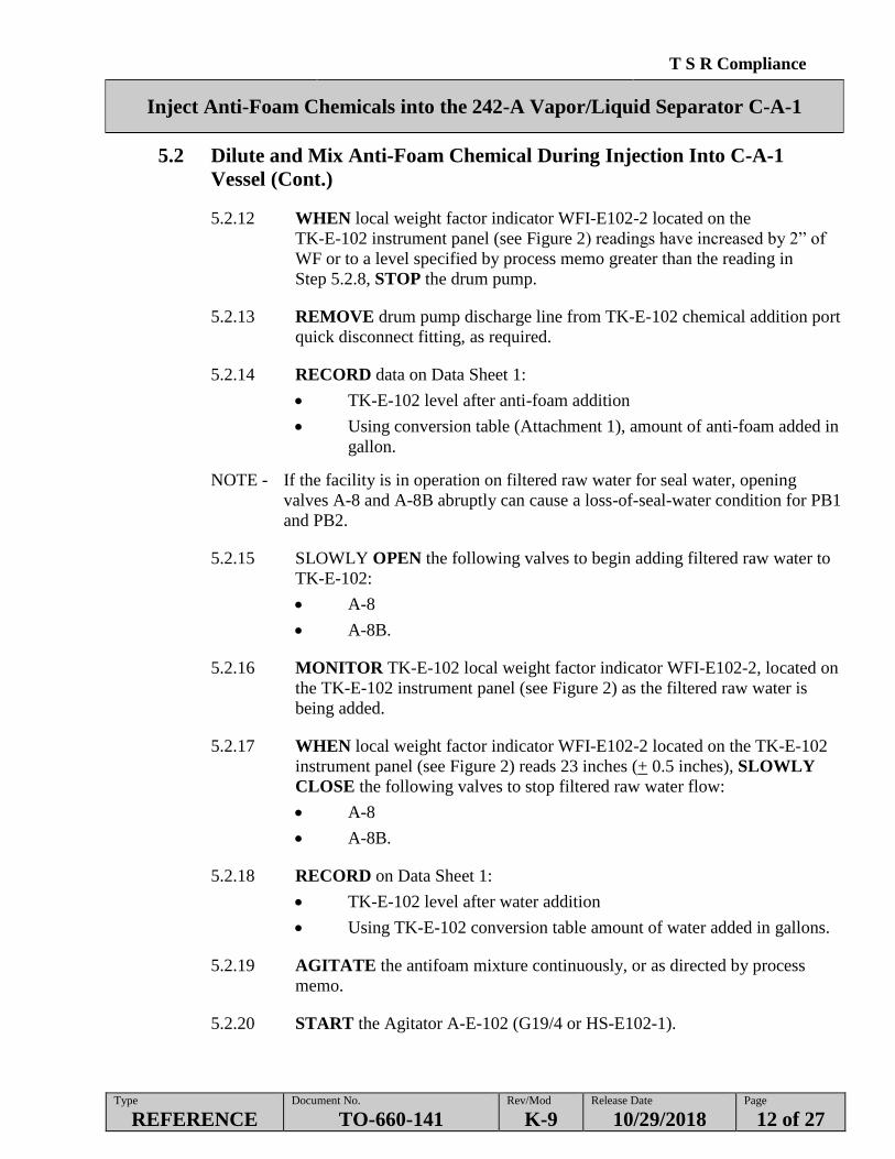
5.2.12 WHEN local weight factor indicator WFI-E102-2 located on the
TK-E-102 instrument panel (see Figure 2) readings have increased by 2” of
WF or to a level specified by process memo greater than the reading in
Step 5.2.8, STOP the drum pump.
5.2.13 REMOVE drum pump discharge line from TK-E-102 chemical addition port
quick disconnect fitting, as required.
5.2.14 RECORD data on Data Sheet 1:
TK-E-102 level after anti-foam addition
Using conversion table (Attachment 1), amount of anti-foam added in
gallon.
NOTE - If the facility is in operation on filtered raw water for seal water, opening
valves A-8 and A-8B abruptly can cause a loss-of-seal-water condition for PB1
and PB2.
5.2.15 SLOWLY OPEN the following valves to begin adding filtered raw water to
TK-E-102:
A-8
A-8B.
5.2.16 MONITOR TK-E-102 local weight factor indicator WFI-E102-2, located on
the TK-E-102 instrument panel (see Figure 2) as the filtered raw water is
being added.
5.2.17 WHEN local weight factor indicator WFI-E102-2 located on the TK-E-102
instrument panel (see Figure 2) reads 23 inches (+ 0.5 inches), SLOWLY
CLOSE the following valves to stop filtered raw water flow:
A-8
A-8B.
5.2.18 RECORD on Data Sheet 1:
TK-E-102 level after water addition
Using TK-E-102 conversion table amount of water added in gallons.
5.2.19 AGITATE the antifoam mixture continuously, or as directed by process
memo.
5.2.20 START the Agitator A-E-102 (G19/4 or HS-E102-1).

T S R Compliance
Inject Anti-Foam Chemicals into the 242-A Vapor/Liquid Separator C-A-1
Type
REFERENCE Document No.
TO-660-141 Rev/Mod
K-9 Release Date
10/29/2018 Page
13 of 27
5.3 Inject Anti-Foam Emulsion Into C-A-1 Vessel
Set Chemical Injection Pump P-E-102 Speed Control
NOTE: Process Memo or Supervision can request a flowrate setpoint from 0.03 to 0.07
gpm. Unless otherwise instructed by supervision, flowrate setpoint will be 0.05
gpm. Anti-Foam injection pump P-E-102 local Speed Controller is located on top
of the pump, facing West wall.
5.3.1 ENSURE FIC-E102 (G19/10) is SET to AUTO with a setpoint of 0.05 or
flowrate specified by Process Memo or supervision.
Prepare Anti-Foam Injection System Flowpath
5.3.2 ENSURE TK-E-102 Drain valve HV-A-6 is CLOSED.
5.3.3 OPEN the following valve (Anti-Foam Injection Pump P-E-102 suction and
discharge):
A-7
A-5.
5.3.4 ENSURE the following block valves, located on the Condenser Room 5th
level, are OPEN and the Anti-Foam injection pump P-E-102 discharge valve:
Valve 5-37
Valve 5-42.
Start Anti-Foam Injection Pump
5.3.5 START Anti-Foam Injection Pump P-E-102 (G19/7, F35 or HS-E101-2).
5.3.6 CHECK that Anti-Foam Emulsion flowrate on FIC-E102 (G19/10) is 0.05
(0.03 to 0.07) gpm or the flowrate specified by Process Memo or supervision.
5.3.7 CONTROL Anti-Foam Emulsion flowrate by using TK-E-102 dropout rate
Data Sheet 2 - TK-E-102 dropout rate ROUND SHEET at the direction of the
Shift Manager.
5.3.8 IF Anti-Foam Injection Pump P-E-102 (G19/7, F35) did not start ENSURE
pump P E 102 Stroke Controller OVERRIDE switch is in the AUTO
position. (See Figure 1)

T S R Compliance
Inject Anti-Foam Chemicals into the 242-A Vapor/Liquid Separator C-A-1
Type
REFERENCE Document No.
TO-660-141 Rev/Mod
K-9 Release Date
10/29/2018 Page
14 of 27
5.3 Inject Anti-Foam Emulsion Into C-A-1 Vessel (Cont.)
Monitor Tank Level
NOTE - The A-E-102 Agitator will automatically shut OFF at a Lo level of 12 inches.
The A-E-102 Antifoam Injection Pump will automatically shut down at a LoLo
level of 5 inches.
5.3.9 CHECK TK-E-102 level every three hours while Anti-Foam Emulsion is
being injected on one of the following instruments:
WFI-E102 ANTIFOAM TANK WT FACTR (G19, F35)
Local Weight Factor Indicator WFI-E102-2, located on the TK-E-102
Instrument panel in the AMU room. (See Figure 2)
5.3.10 WHEN TK-E-102 level has decreased to approximately 13 inches as read on
WFI-E102 (G19, F35) or WFI-E102-2, or P-E-102 Antifoam Tank Agitator
(G19/7, F35) has automatically shut down, PERFORM Section 5.2 to mix
another batch of Antifoam chemicals and continue pumping.
5.3.11 IF shutting down Antifoam system PERFORM Section 5.4.
T S R Compliance
Inject Anti-Foam Chemicals into the 242-A Vapor/Liquid Separator C-A-1
Type
REFERENCE Document No.
TO-660-141 Rev/Mod
K-9 Release Date
10/29/2018 Page
15 of 27
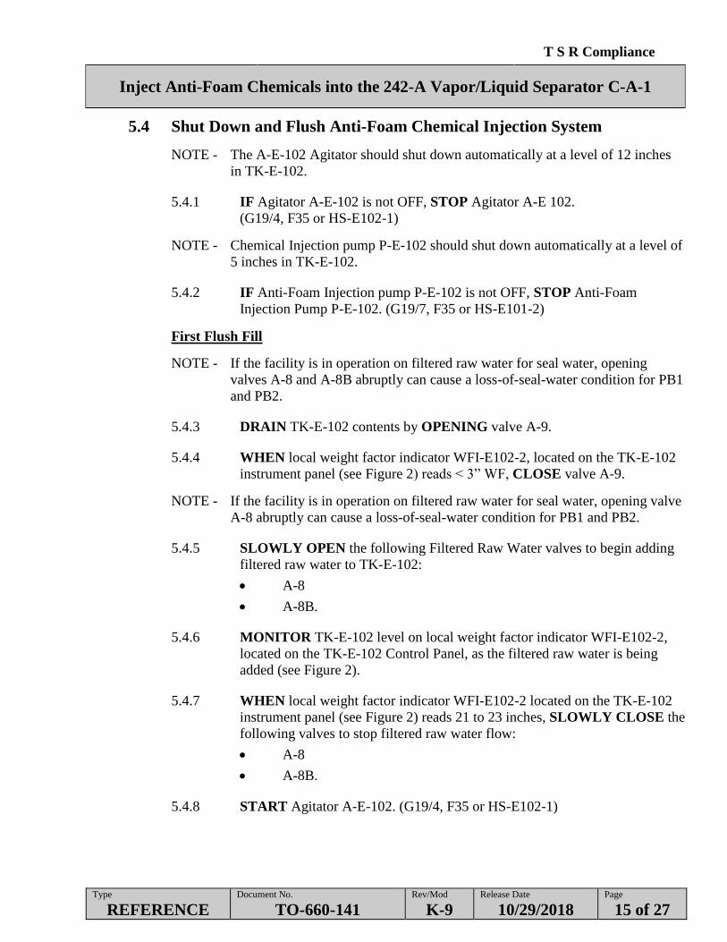
5.4 Shut Down and Flush Anti-Foam Chemical Injection System
NOTE - The A-E-102 Agitator should shut down automatically at a level of 12 inches
in TK-E-102.
5.4.1 IF Agitator A-E-102 is not OFF, STOP Agitator A-E 102.
(G19/4, F35 or HS-E102-1)
NOTE - Chemical Injection pump P-E-102 should shut down automatically at a level of
5 inches in TK-E-102.
5.4.2 IF Anti-Foam Injection pump P-E-102 is not OFF, STOP Anti-Foam
Injection Pump P-E-102. (G19/7, F35 or HS-E101-2)
First Flush Fill
NOTE - If the facility is in operation on filtered raw water for seal water, opening
valves A-8 and A-8B abruptly can cause a loss-of-seal-water condition for PB1
and PB2.
5.4.3 DRAIN TK-E-102 contents by OPENING valve A-9.
5.4.4 WHEN local weight factor indicator WFI-E102-2, located on the TK-E-102
instrument panel (see Figure 2) reads < 3” WF, CLOSE valve A-9.
NOTE - If the facility is in operation on filtered raw water for seal water, opening valve
A-8 abruptly can cause a loss-of-seal-water condition for PB1 and PB2.
5.4.5 SLOWLY OPEN the following Filtered Raw Water valves to begin adding
filtered raw water to TK-E-102:
A-8
A-8B.
5.4.6 MONITOR TK-E-102 level on local weight factor indicator WFI-E102-2,
located on the TK-E-102 Control Panel, as the filtered raw water is being
added (see Figure 2).
5.4.7 WHEN local weight factor indicator WFI-E102-2 located on the TK-E-102
instrument panel (see Figure 2) reads 21 to 23 inches, SLOWLY CLOSE the
following valves to stop filtered raw water flow:
A-8
A-8B.
5.4.8 START Agitator A-E-102. (G19/4, F35 or HS-E102-1)

T S R Compliance
Inject Anti-Foam Chemicals into the 242-A Vapor/Liquid Separator C-A-1
Type
REFERENCE Document No.
TO-660-141 Rev/Mod
K-9 Release Date
10/29/2018 Page
16 of 27
5.4 Shut Down and Flush Anti-Foam Chemical Injection System (Cont.)
5.4.10 ENSURE FIC-E102 (G19/10) is SET to AUTO with a setpoint of 0.1 or
flowrate specified by supervision.
5.4.11 START Anti-Foam Injection Pump P-E-102 (G19/7, F35 or HS-E101-2).
5.4.12 CHECK TK-E-102 level every three hours while Anti-Foam flush is being
injected on one of the following instruments:
WFI-E102 ANTIFOAM TANK WT FACTR (G19, F35) or
Local Weight Factor Indicator WFI-E102-2, located on the TK-E-102
Instrument panel in the AMU room. (See Figure 2)
NOTE: The Agitator A-E-102 should shut down automatically at a level of 12 inches in
TK-E-102.
5.4.13 IF Agitator A-E-102 is not OFF, STOP Agitator A-E-102.
(G19/4, F35 or HS-E102-1).
NOTE: Anti-Foam Injection Pump P-E-102 should shut down automatically at a level of
5 inches in TK-E-102.
5.4.14 IF Anti-Foam Injection Pump P-E-102 is not OFF, STOP Anti-Foam
Injection Pump P-E-102. (G19/7, F35 or HS-E101-2)

T S R Compliance
Inject Anti-Foam Chemicals into the 242-A Vapor/Liquid Separator C-A-1
Type
REFERENCE Document No.
TO-660-141 Rev/Mod
K-9 Release Date
10/29/2018 Page
17 of 27
5.4 Shut Down and Flush Anti-Foam Chemical Injection System (Cont.)
Flush the Anti-Foam line
NOTE - If the facility is in operation on filtered raw water for seal water, opening valve
A-8 abruptly can cause a loss-of-seal-water condition for PB1 and PB2.
5.4.15 CLOSE Anti-Foam injection pump P-E-102 suction valve A-7.
5.4.16 SLOWLY OPEN filtered water valve A-8.
5.4.17 SLOWLY OPEN filtered water injection line flush valve A-8A AND
FLUSH approximately 10-30 minutes.
5.4.18 SLOWLY CLOSE filtered water valve A-8.
5.4.19 OPEN Anti-Foam injection pump P-E-102 suction valve A-7.
5.4.20 OPEN TK-E-102 drain valve A-9.
5.4.21 OPEN P-E-102 suction line drain valve HV-A-6.
5.4.22 AFTER drain flow has stopped, CLOSE the following valves in the order
given:
A-8A
HV-A-6
A-9
A-7.
5.4.23 CLOSE the following block valves in the order given:
5-37
5-42.
5.4.24 NOTIFY Shift Manager the Anti-Foam Chemical Injection System has been
shut down.

T S R Compliance
Inject Anti-Foam Chemicals into the 242-A Vapor/Liquid Separator C-A-1
Type
REFERENCE Document No.
TO-660-141 Rev/Mod
K-9 Release Date
10/29/2018 Page
18 of 27
5.5 System Flush
Flush the Anti-Foam system
NOTE - If the facility is in operation on filtered raw water for seal water, opening valve
A-8 abruptly can cause a loss-of-seal-water condition for PB1 and PB2.
- Section 5.5 may be performed at any time as directed by the Shift Manager.
5.5.1 ENSURE the following block valves, located on the Condenser Room 5th
level, are OPEN:
Valve 5-37
Valve 5-42.
5.5.2 ENSURE the following valves are CLOSED. (See Figure 1):
A-7
A-8
A-8A
A-8B
A-9
A-21
HV-A-6.
5.5.3 ENSURE the TK-E-102 Dip Tube Air Purge controllers FIC-E102-1 and
FIC-E102-2, located on the TK-E-102 Control Panel, are set at
0.5 to 1.5 scfh. (See Figure 2)
5.5.4 ENSURE valve A-5 is OPEN. (See Figure 1)
5.5.5 SLOWLY OPEN the following Filtered Raw Water valves to begin adding
filtered raw water to TK-E-102:
A-8
A-8B.
5.5.6 MONITOR TK-E-102 level on local weight factor indicator WFI-E102-2,
located on the TK-E-102 Control Panel, AS the filtered raw water is being
added (see Figure 2)
5.5.7 WHEN local weight factor indicator WFI-E102-2 located on the TK-E-102
instrument panel (see Figure 2) reads 21 to 23 inches, SLOWLY CLOSE the
following valves to stop filtered raw water flow:
A-8
A-8B.

T S R Compliance
Inject Anti-Foam Chemicals into the 242-A Vapor/Liquid Separator C-A-1
Type
REFERENCE Document No.
TO-660-141 Rev/Mod
K-9 Release Date
10/29/2018 Page
19 of 27
5.5 System Flush(Cont.)
5.5.8 OPEN Anti-Foam injection pump P-E-102 suction valve A-7.
5.5.9 ENSURE FIC-E102 (G19/10) is SET to AUTO with a setpoint of 0.1 or
flowrate specified by supervision.
5.5.10 START Anti-Foam Injection Pump P-E-102 (G19/7, F35 or HS-E101-2).
5.5.11 CHECK TK-E-102 level every three hours while Anti-Foam flush is being
injected on one of the following instruments:
WFI-E102 ANTIFOAM TANK WT FACTR (G19, F35)
Local Weight Factor Indicator WFI-E102-2, located on the TK-E-102
Instrument panel in the AMU room. (See Figure 2).
5.5.12 OPERATE P-E-102 for duration specified by the Shift Manager.
5.5.13 STOP P-E-102 when directed by the Shift Manager.
5.5.14 CLOSE valve A-7.
5.5.15 IF directed to DRAIN TK-E-102, OPEN valve A-9.
5.5.16 ENSURE valve A-9 is closed.
5.5.17 ENSURE valves 5-37 and 5-42 are closed.

T S R Compliance
Inject Anti-Foam Chemicals into the 242-A Vapor/Liquid Separator C-A-1
Type
REFERENCE Document No.
TO-660-141 Rev/Mod
K-9 Release Date
10/29/2018 Page
20 of 27
5.6 Anti-Foam line Flush
Flush the Anti-Foam line
NOTE - If the facility is in operation on filtered raw water for seal water, opening valve
A-8 abruptly can cause a loss-of-seal-water condition for PB1 and PB2.
- Section 5.6 may be performed at any time as directed by the Shift Manager.
5.6.1 ENSURE valves 5-37 and 5-42 are OPEN.
5.6.2 CLOSE Anti-Foam injection pump P-E-102 suction valve A-7.
5.6.3 SLOWLY OPEN filtered water valve A-8.
5.6.4 SLOWLY OPEN filtered water injection line flush valve A-8A AND
FLUSH approximately 10 – 30 minutes.
5.6.5 SLOWLY CLOSE filtered water valve A-8.
5.6.6 OPEN Anti-Foam injection pump P-E-102 suction valve A-7.
5.6.7 ENSURE valves 5-37 and 5-42 are CLOSED.

T S R Compliance
Inject Anti-Foam Chemicals into the 242-A Vapor/Liquid Separator C-A-1
Type
REFERENCE Document No.
TO-660-141 Rev/Mod
K-9 Release Date
10/29/2018 Page
21 of 27
5.7 Records
5.7.1 PERFORM the following for records identified within this procedure.
5.7.1.1 RECORD the number of times the record was generated in
applicable column,
OR
PLACE a check mark () in the N/A column.
5.7.1.2 SUBMIT the package to FWS/OE/Shift Manager.
Records Submittal Checklist
Number
of times
completed
N/A
()
Data Sheets
Data Sheet 1 – Anti-Foam Makeup
Data Sheet 2 - TK-E-102 dropout rate ROUND SHEET
Signature Sheets
Signature Sheet 1
FWS/OE/Shift Manager SEND the completed records to the Central Shift Office for
records retention.
/ /
Signature Print (First & Last) Date
FWS/OE/Shift Manager
The record custodian identified in the company-level Records Inventory and Disposition
Schedule (RIDS) is responsible for record retention in accordance with
TFC-BSM-IRM_DC-C-02.

T S R Compliance
Inject Anti-Foam Chemicals into the 242-A Vapor/Liquid Separator C-A-1
Type
REFERENCE Document No.
TO-660-141 Rev/Mod
K-9 Release Date
10/29/2018 Page
22 of 27
Data Sheet 1 – Anti-Foam Makeup
Initial Fill Only
**** Process status
(i.e. feed/slurrying, recirc
with vacuum, recirc
without vacuum)**
% active
ingredient in
anti-foam to
be made up
Current
TK-E-102
tank level
TK-E-102
level after water
addition
TK-E-102
level after anti-
foam addition
Amount of
water
added
Amount of anti-
foam added***
Date Time 4% A
(Inches)
B
(Gal*)
C
(Inches)
D
(Gal*)
E
(Inches)
F
(Gal*)
D – B =
(Gal)
F – D =
(Gal)
4%
Refill
Process status
(i.e. feed/slurrying,
recirc with vacuum,
recirc without
vacuum)**
% active
ingredient in
anti-foam to be
made up
Current
TK-E-102
tank level
TK-E-102
level after anti-foam
addition
TK-E-102
level after water
addition
Amount of
water
added
Amount of anti-
foam added
***
Date Time 4%
A
(Inches)
B
(Gal*)
C
(Inches)
D
(Gal*)
E
(Inches)
F
(Gal*)
F – D =
(Gal)
D – B =
(Gal)
4%
4%
4%
4%
4%
4%
4%
4%
* Use TK-E-102 tank conversion table for calculation of gallons of water added or gallons of anti-foam added
** If process status is recirculation with or without vacuum, request permission to secure the anti-foam system
*** No more than 165 gallons of undiluted anti-foam is allowed to be added to C-A-1 at one time (242-A TSR AC 5.9.1)
**** N/A if not an Initial Fill
/ /
Signature Print (First and Last) Date
Shift Manager /OE

T S R Compliance
Inject Anti-Foam Chemicals into the 242-A Vapor/Liquid Separator C-A-1
Type
REFERENCE Document No.
TO-660-141 Rev/Mod
K-9 Release Date
10/29/2018 Page
23 of 27
Data Sheet 2 - TK-E-102 dropout rate ROUND SHEET
A-1/A-2 record anti-foam tank level every three hours and ensure dropout rate listed below,
per plant status.
Start-up: 2” level drop per hour. (6” drop for three hours)
After boil-off established: 0.2” level drop per hour. (0.6” drop for three hours)
OR as stated per Process Memo.
If reading obtained is outside of above values, NOTIFY SM.
DATE TIME Tank E-
102 level
Level change
from previous
level reading
OPERATOR
INITIAL(1)
242-A Shift
Manager Review
Initials(1)
COMMENTS
(1) All personnel performing signature required steps shall enter their signature, printed name,
and initials on Signature Sheet 1

T S R Compliance
Inject Anti-Foam Chemicals into the 242-A Vapor/Liquid Separator C-A-1
Type
REFERENCE Document No.
TO-660-141 Rev/Mod
K-9 Release Date
10/29/2018 Page
24 of 27
Attachment 1 – TK-E-102 Conversion Table
Weight Factor Gallons
0 0
1 4.0
2 8.0
3 11.0
4 14.0
5 16.9
6 19.8
7 22.7
8 25.6
9 28.6
10 31.5
11 34.5
12 37.4
13 40.4
14 43.4
15 46.4
16 49.3
17 52.2
18 55.1
19 58.1
20 61.0
21 64.0
22 66.9
23 69.9
24 72.8
25.5 78.0
Initial Pre-dilute Concentrations for Liquid Silicon Anti-Foam Emulsion
% Active Ingredient in Antifoam Water in Weight Factor
(+ 0.5 WF)
Antifoam in Weight Factor
(+ 0.5 WF)
4% 19” WF 4” WF
7% 15” WF 8” WF
10% 11” WF 12” WF
Dilute and Mix Anti-Foam Emulsion During Injection Into C-A-1 Vessel
4% Fill to 23" WF 2” WF*
7% Fill to 23" WF 3.5” WF*
10% Fill to 23" WF 5” WF*
*Antifoam values are based on 13” WF

T S R Compliance
Inject Anti-Foam Chemicals into the 242-A Vapor/Liquid Separator C-A-1
Type
REFERENCE Document No.
TO-660-141 Rev/Mod
K-9 Release Date
10/29/2018 Page
25 of 27
Signature Sheet 1
All personnel performing signature required steps shall enter their printed name, signature, and initials
below.
Name (Printed First & Last) Signature Initials

T S R Compliance
Inject Anti-Foam Chemicals into the 242-A Vapor/Liquid Separator C-A-1
Type
REFERENCE Document No.
TO-660-141 Rev/Mod
K-9 Release Date
10/29/2018 Page
26 of 27
Figure 1 - Anti-Foam Chemical Injection System
CHEMICAL
ADDITION
PORT
A-8 Filtered Raw Water ¾”PSV-E102-1
Set @ 60 psig A-21 Vent
FE-E102-1
P-E-102 STROKECONTROLLEROVERRIDE SWITCH
P-E-102 MOTOR
To Drain
A-5
A-7
HV-A-6To Drain
A-9
TK-E-102
A-8B
A-8A
PCV-FRM-1
T S R Compliance
Inject Anti-Foam Chemicals into the 242-A Vapor/Liquid Separator C-A-1
Type
REFERENCE Document No.
TO-660-141 Rev/Mod
K-9 Release Date
10/29/2018 Page
27 of 27
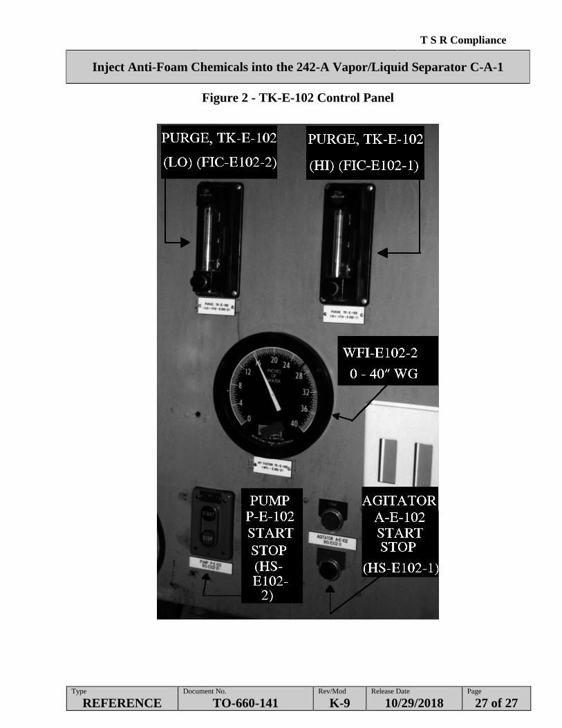
Figure 2 - TK-E-102 Control Panel
Related Documents