TAE ANTI-SEISMI C DESIG N OF NUCLEA R INSTALLATION S LA CONCEPTION . .ANTISISMIQU E DE S INSTALLATION S Compte -reodo NUCLÉAIRE S d'une Réunion de Spécialiste s OECD - OCDE 1-3 Dec . 197 5 NUCLEAR ENERGY AGENC Y ORGANISATION FOR ECONOMIC CO-OPERATION AND DEVELOPMEN T AGENCE POUR L'ENERGIE NUCLEAIR E ORGANISATION DE COOPERATION ET DE DEVELOPPEMENT ECONOMIQUE S Proceeding s of a Specialist Meeting

Welcome message from author
This document is posted to help you gain knowledge. Please leave a comment to let me know what you think about it! Share it to your friends and learn new things together.
Transcript

TAE ANTI-SEISMI CDESIGN
OF NUCLEARINSTALLATIONS
LA CONCEPTION..ANTISISMIQUE
DESINSTALLATIONS
Compte -reodo
NUCLÉAIRESd'une Réunion de Spécialistes
OECD - OCDE1-3 Dec. 1975
NUCLEAR ENERGY AGENC YORGANISATION FOR ECONOMIC CO-OPERATION AND DEVELOPMEN T
AGENCE POUR L'ENERGIE NUCLEAIR EORGANISATION DE COOPERATION ET DE DEVELOPPEMENT ECONOMIQUE S
Proceedingsof a Specialist Meeting

Proceedings of the Specialist Meeting o n
TAE ANTI-SEISMIC DESIGNOF NUCLEAR INSTALLATION S
OECD- PARIS, 1st-3rd DECEMBER 1975
Compte rendu de la Réunion de Spécialistes sur
LA CONCEPTION ANTISISMIQUEDES INSTALLATIONS NUCLÉAIRES
OCDE-PARIS, ler-3 DÉCEMBRE 1975
COMMITTEE ON THE SAFETY OF NUCLEAR INSTALLATION S
NUCLEAR ENERGY AGENC YORGANISATION FOR ECONOMIC CO-OPERATION AND DEVELOPMEN T
COMITE SUR LA SURETE DES INSTALLATIONS NUCLEAIRE S
AGENCE POUR L'ENERGIE NUCLEAIR EORGANISATION DE COOPERATION ET DE DEVELOPPEMENT ECONOMIQUES
The Organisation for Economic Co-operation and Devel-opment (OECD) was set up under a Convention signed in Paris o n14th December, 196o, which provides that the OECD shall pro -mote policies designed :
to achieve the highest sustainable economic growth andemployment and a rising standard of living in Membercountries, while maintaining financial stability, and thu sto contribute to the development of the world economy ;to contribute to sound economic expansion in Member aswell as non-member countries in the process of economi cdevelopment ;to contribute to the expansion of world trade on a multi -lateral, non-discriminatory basis in accordance with inter-national obligations .
The Members of OECD are Australia, Austria, Belgium, Cana -da, Denmark, Finland, France, the Federal Republic of Germany ,Greece, Iceland, Ireland, Italy, Japan, Luxembourg, the Nether -lands, New Zealand, Norway, Portugal, Spain, Sweden, Switzer-land, Turkey, the United Kingdom and the United States .
The OECD Nuclear Energy Agency - (NEA) was established onloth April 1972, replacing OECD's European .Nuclear Energy Agency(ENEA) on the adhesion of japan as a full Member . NEA now groupseighteen European Member countries of OECD and Australia, Canada an djapan, with the United States as an Associated country . The Commissio nof the European Communities takes part in the work of the Agency .
The objectives of NEA remain substantially those of ENEA, namelythe orderly development of the uses of nuclear energy for peaceful purposes .This is achieved by :
- assessing the fùture role of nuclear energy as a contributor to eco-nomic progress, and encouraging co-operation between governmentstowards its optimum development ;
- encouraging harmonisation of governments' regulatory policies andpractices in the nuclear field, with particular reference to healt hand safety, radioactive waste management and nuclear third partyliability and insurance ;
-- forecasts of uranium resources, production and demand:-- operation of common services and encouragement of co-operatio n
in the field of nuclear energy information ;-- sponsorship of research and development undertakings jointly orga-
nised and operated by OECD countries .In these tasks NEA works in close collaboration with the International
Atomic Energy Agency, with which it has concluded a Co-operation Agree -ment, as well as with other international organisations in the nuclear field .
OECD, 1976 .Queries concerning permissions or translation rights should beaddressed to :
Director of Information, OEC D2, rue André-Pascal, 75775 PARIS CEDEX 16, France .
L'Organisation de, Coopération et de Développement Écono-miques (OCDE), qui a été instituée par une Convention signée l e14 décembre ig6o, à Paris, a pour objectif de promouvoir de spolitiques visant :
- à réaliser la plus forte expansion possible de l'économie e tde l'emploi et une progression du niveau de vie dans lespays Membres, tout en maintenant la stabilité financière ,et contribuer ainsi au développement de l'économi emondiale ;
- à contribuer à une saine expansion économique dans le spays Membres, ainsi que non membres, en voie de déve-loppement économique ;
- à contribuer à l'expansion du commerce mondial sur un ebase multilatérale et non discriminatoire, conformémen taux obligations internationales .
Les Membres de l'OCDE sont : la République Fédéraled'Allemagne, l'Australie, l'Autriche, la Belgique, le Canada, leDanemark, l'Espagne, les États-Unis, la Finlande, la France, l aGrèce, l'Irlande, l'Islande, l'Italie, le Japon, le Luxembourg, l aNorvège, la Nouvelle-Zélande, les Pays-Bas, le Portugal, le Royaume -Uni, la Suède, la Suisse et la Turquie .
L'Agence de l'OCDE pour l'Énergie Nucléaire (AEN) a été insti-tuée le 20 avril 1972, en remplacement de l'Agence Européenne_ pou rl'Énergie Nucléaire de l'OCDE (ENEA) par suite de l'adhésion duJapon en tant que Membre de plein exercice . L'AENgroupe à présent dix-
it pays européens Membres de l'OCDE ainsi que l'Australie, le Canad aet le japon ; les États-Unis y participent en tant que Membre associé. Enoutre la Commission des Communautés Européennes participe également au xtravaux de l'Agence .
Les objectifs de l'AEN restent pour la plupart les mêmes que ceux d el'ENEA et concernent la promotion du développement harmonieux des utili-sations pacifiques de l'énergie nucléaire. Elle entreprend à cet effet :
d'évaluer le rôle futur de l 'énergie nucléaire dans la réalisation d uprogrès économique et d'encourager la coopération entre les gou-vernements en vue de son développement optimal ;de promouvoir une harmonisation des politiques et pratiques régle-mentaires des gouvernements dans le domaine nucléaire, en parti-culier pour la protection de la santé et la sécurité, la gestion de sdéchets radioactifs, la responsabilité civile et l'assurance en matièr enucléaire ;d'établir des prévisions sur les ressources, la production et la de-mande d'uranium ;d'assurer le fonctionnement de services communs et d'encourager lacoopération dans le domaine de l'information nucléaire ;de patronner des entreprises de recherche et de développement organi-sées et exploitées en commun par des pays Membres de l'OCDE.
Pour remplir ces fonctions, l'AEN travaille en étroite collaboratio navec l'Agence Internationale de l ' Énergie Atomique (avec laquelle elle aconclu un accord de coopération) ainsi qu'en liaison avec d'autres organisa -tions internationales dans le domaine nucléaire .
Qc OCDE, 1976 .Les demandes de reproduction ou de traduction doivent êtr eadressées à :
M. le Directeur de l'Information, OCD E2, rue André-Pascal, 75775 PARIS CEDEX 16, France .
.r,

FOREWORD
The question of anti-seismic precautions to b etaken when building nuclear power plants is important, as anatural consequence of its actuality and of the diversity o fthe techniques involved . Probabilistic methods play an in-creasingly important role . Generally speaking, safety research ,and more particularly nuclear safety research, finds itsel fbound to become increasingly quantitative .
In this perspective, the NEA Committee on the Safetyof Nuclear Installations (CSNI) decided to sponsor a specia-lists' meeting on Anti-Seismic Design of Nuclear Installations .This meeting was in fact the second one in a series of specia -lists' meetings on anti-seismic design of nuclear power plant sinaugurated at Pisa (Italy) in October 1972 by the NEA Committe eon Reactor Safety Technology (CREST), CSNI's predecessor .
The objectives of the meeting were, as well as farthe mutual information of the participants, to make progres son a number of questions, and to express in the discussion scommon views, opinions, and conclusions likely to help th ework of safety specialists .
It was therefore thought interesting that conclu -sions and synthesis recommendations be prepared immediatelyafter each session by the Session Chairmen and Scientifi cSecretaries . We warmly thank Messrs . Bork _and Mohammadiou nfor Session I, Prof . Rothé and Mr . Barbreau for Session II ,Prof . Shibata and Mr . Livolant for Session III, Mr . Parkerand Miss Jeanpierre for Session IV, Prof . Ambraseys andMr. Berriaud for Session V, Messrs . Kissenpfennig and Houz éfor Session VI for the quick and excellent work they did .
We thank also the participants for their willingnes sto write their questions and answers on special forms hande dout during the sessions . Their own text, reproduced in th eoriginal language (English or French) and without any signif -icant change, constitutes the summary record of the discussion spublished in this book . We did not attempt to improve the lin-guistic quality of these documents, so as to avoid unnecessari -ly delaying publication of the proceedings and risking th edistortion of the authors' opinions .
Our gratitude goes particularly to Mr . Castes ,Chairman of the meeting, who was also its scientific secretaryand its leader . He was the mainspring of the meeting .
CSNI Secretariat
3

AVANT-PROPOS
La question des précautions parasismiques à prendr elors de la construction des centrales nucléaires est. importante ,par suite de son actualité et de la diversité des technique simpliquées . Les méthodes probabilistes y jouent un rôle de plu sen plus considérable . De manière plus générale, la recherch een matière de sûreté, surtout lorsqu'il s'agit de sûreté nu-cléaire, se voit obligée de devenir de plus en plus quantita-tive .
C'est dans cette perspective que le Comité de l'AENsur la Sûreté des Installations Nucléaires (CSIN) a décidé d epatronner une réunion de spécialistes sur la Conception Anti -sismique des Installations Nucléaires . Cette réunion était enfait la deuxième dans une série de réunions de spécialiste ssur la conception antisismique des centrales nucléaires inau -gurée à Pise (Italie) en octobre 1972 par le Comité de l'AENsur la Technologie de la Sûreté des Réacteurs (CREST), prédé -cesseur du CSIN .
Les objectifs de la réunion étaient, outre l'infor-mation mutuelle des participants, de faire faire des progrè sà un certain nombre de questions, et d'exprimer au cours de sdiscussions des points de vues communs, des avis, des conclu-sions susceptibles d'aider le travail des spécialistes d esûreté .
Il était intéressant par conséquent que des conclu-sions et des recommandations de synthèse soient préparées immé-diatement après chaque séance par les Présidents et Secrétaire sscientifiques de Séance . Nous remercions vivement MM. Bork e tMohammadioun pour la Séance I, MM . Rothé et Barbreau pour laSéance II, MM . Shibata et Livolant pour la Séance III ,M . Parker et Mlle Jeanpierre pour la Séance IV, MM . Ambraseyset Berriaud pour la Séance V, et MM . Kissenpfennig et Houz épour la Séance VI du travail excellent, et rapide, qu'ils ontfourni .
Nous remercions également les participants d'avoi rbien voulu rédiger leurs questions et leurs réponses sur de sformulaires spéciaux distribués pendant les séances . C'es tleur texte, reproduit dans la langue originale (anglais oufrançais) et sans changement notable, qui constitue le résum édes discussions publié dans ce volume . Nous n'avons pas essayéd'améliorer la qualité linguistique de ces documents, de ma -nière à éviter de retarder inutilement la parution du compt erendu et de risquer de trahir la pensée des auteurs .
4

Notre gratitude s'adresse particulièrement àM . Costes, Président de la réunion, mais aussi son secrétair escientifique et son animateur . C'est lui qui a été la chevill eouvrière du succès de la réunion .
Le Secrétariat du CSIN
5

LIST OF REPRESENTATIVES TO CSNI (MARCH 1976 )LISTEDES REPRESENTANTS AU CSIN (MARS 1976 )
AustraliaAustralie
AustriaAutriche
BelgiumBelgique
Canada
DenmarkDanemark
FinlandFinland e
Franc e
F .R . of GermanyR.F . d'Allemagn e
Greec erréceIcelandIsland e
IrelandIrland e
ItalyItali e
J~aeon
Luxembourg
The NetherlandsPays-Bas
Mr . D .W . Crancher
Dr . P . Vychyti l
M. F . LéonardM. G. Penell e
Mr . J .H . JennekensMr . L . Peas e
Mr . P . Frederiksen
No representativ ePas de représentant
M . J . BourgeoisM . P . Tanguy
Prof . A . BirkhoferDipl .-Ing . H .D . Seipe lDr. H . Schnurer
Prof . N .,Chrysochoide sMr. J . Karangelo s
No representativ ePas de représentant
No representativ ePas de représentant
Mr. P . GiulianiMr . C . Zaffiro
Mr . Y . Matsud aMr . K . Matsu iProf . H . Uchida
No representativ ePas de représentant
Mr . R .G . ScholvinckMr . C .J . van Daatselaar
6
IAEA (Observer )AIEA (Observateur )
NEA (Secretariat )(Secrétariat )
PNorworvege
Portugal
SpainEspagne
SwedenSuède
SwitzerlandSuiss e
TurkeyTurqui e
United KingdomRoyaume-Uni
United StatesÉtats-Unis
CEC
Mr . J .M . D$derleinMr. E . Jansen
Mr. A . Marques de Carvalh o
Dr . A . Alonso
Dr . L . CarlbomDr. A . Hedgran
Dr. P . CourvoisierMr. G . Pr ant l
Prof . N . AybersMr . A .Y . Erturan
Prof . F .R . Farme rMr . R . GausdenMr . E .V . GilbyMr . G .H . Kinchin
Dr . W .H . HannumDr . H .J .C . Kout s
Mr . R . KlersyMr. W . Vinck
Mr . J .C . McCullen
Mr. K .B . Stadi e(Head, Division of Nuclea rSafety -Chef de la Division de l aSûreté Nucléaire )
Dr . J . Royen(Secretary, CSNI -Secrétaire du CSIN )
Mr . N . de Boer
7
TABLE OF CONTENTS
TABLE DES MATIÈRES
Foreword
Avant-propos
SESSION Î - INTRODUCTIONSEANCE I - INTRODUCTION
Chairman - Président : Mr . M . Bork
SUMMARY OF SESSION I 1 4RESUME DE LA SEANCE I 1 6
1 . RAPPORT SUR LA REUNION DE SPECIALISTES OCDE (AEN)CREST SUR LA CONCEPTION ANTISISMIQUE DES CENTRALESNUCLEAIRES ORGANISEE A PISE (ITALIE) EN OCTOBRE197 2
D . Costes, France 1 8
2 . RAPPORT SUR LA CINQUIEME CONFERENCE MONDIATF DEGENIE PARASISMIQUE ORGANISEE A ROME (ITALIE) ENJUIN 1973C . Plichon, France 23
3 . RAPPORTS SUR LA TROISIEME CONFERENCE INTERNATIONALESUR LA MECANIQUE STRUCTURATF DANS LA TECHNOLOGIEDES REACTEURS (SHIRT) ORGANISEE A LONDRES(ROYAUME-UNI) ET SUR TEFF SÉMINAIRE INTERNATIONALSUR TIFS CONDITIONS EXTREMES DE CHARGEMENT ETPROCEDURES D'ANALYSE DES LIMITES EN MATIERE DEDISPOSITIFS STRUCTURAUX DE PROTECTION DES REACTEUR SET DES STRUCTURES DES ENVELOPPES DE SECURITE(ELCALAP) ORGANISE A BERLIN - SEPTEMBRE 197 5
D . Costes, France 28
4. COMPARATIVE STUDY OF THE PROCEDURES FOR ANTI -SEISMIC DESIGN IN THE MEMBER COUNTRIES OF TEEEUROPEAN ECONOMIC COMMUNITTF SH. Maurer, CEC 31
3
4
8
SESSION II - SEISMOLOGYSEANCE II - SISMOLOGIE
Chairman - Président : Prof . J .P . Roth é
SUMMARY OF SESSION II 40
RESUME DE LA SEANCE II 43
1 . SAFE SHUTDOWN EARTHQUAKE AND OPERATING BASI SEARTHQUAKE DETERMINISTIC AND PROBABILISTI CEVALUATIONSD .K . Shukla, J .F . Kissenpfennig, United States . . . . 46
2 . A METHOD OF DERIVING REFERENCE GROUND MOTIONS FORENGLAND AND WAVE S
A .G . Oliver, United Kingdom 57
3 . THE ASSESSMENT OF SEISMIC DESIGN CRITERIA FO RNUCLEAR POWER STATIONS IN ENGLAND AND WALES
D .J . Mallard, J . Irving, P .A. Corkerton ,United Kingdom 67
4. ETUDES SISMOLOGIQUES EFFECTUEES AU DEPARTEMENT DE
88
SURETE NUCLEAIRE DU COMMISSARIAT A L'ENERGIEATOMIQUE EN VUE DE LA PROTECTION DES INSTALLATIONSNUCLEAIRESA . Barbreau, B . Mohammadioun, H . Ferrieux, France . .
5. EVALUATION QUANTITATIVE DES RISQUES SISMIQUES
D . Costes, France 100
6. CHARACTERISTICS OF STRONG GROUND MOTIONS IN TH ENEAR FIELD OF SMALL MAGNITUDE EARTHQUAKE S
N.N. Ambraseys, United Kingdom
11 3
GENERAL DISCUSSION - DISCUSSION GENERATR 137
SESSION III - SOIL-FOUNDATION INTERACTION
SEANCE III - INTERACTIONSOL-FONDATION
Chairman - Président : Prof . H . Shibat a
SUMMARY OF SESSION III 144
RESUME DE LA SEANCE III 146
Introduction to Session III by the Chairman
Introduction à la Séance III par le Président 148
9
1. CONTINUUM AND FINITE ELEMENT TECHNIQUES FOR SOIL -STRUCTURE INTERACTION ANALYSIS OF DEEPLY EMBEDDE DFOUNDATIONS
J.R. Hall, Jr ., A .P . Michalopoulos, United States 150
2. SEISMIC RESPONSE DUE TO TRAVELLING SHEAR WAVEINCLUDING SOIL-STRUCTURE INTERACTION WITH BASE -MAT UPLIFTJ .P . Wolf, Switzerland 160
3. DESIGN AND RESEARCH ASPECTS OF THE TREATMENT O FEARTH TREMOR EFFECTS ON NUCTRAR POWER PLANTSTRUCTURES AND COMPONENT S
H.J. Dowler, K . Fullard, I .C . Simpson ,United Kingdom 190
4. WAVES PROPAGATION IN SOLID SJ .F . Vernet, France 1 97
5. TEES ELASTOMERES FRETTES ET LES APPUIS A FRICTION ,MOYENS MODERNES DE SUPPORTAGE ANTISISMIQUEC. Plichon, France 203
GENERAL DISCUSSION - DISCUSSION GENERALE 220
SESSION IV - STRUCTURES AND EQUIPMENTS
SEANCE IV - STRUCTURES ET EQUIPEMENTS
Chairman - Président : Mr . J .V . Parker
SUMMARY OF SESSION IV 23 0RESUME DE LA SEANCE IV 23 2
1 . THE NON-STATIONARY RANDOM SEISMIC RESPONSE O FSTRUCTURES
D . Hitchings, United Kingdom 234
2. EARTHQUAKE RESPONSE SPECTRA FOR NUCLEAR POWE RPLANTS USING GRAPHICAL METHODS
C .G . Duff, Canada 248
3. METHODES USUELLES D'ANALYSE SISMIQUE DES CENTRALES .OBTENTION DIRECTE DES SPECTRES DE PLANCHER .APPLICATIONS A UNE CENTRALE A NEUTRONS RAPIDES E TUNE CENTRALE A EAU PRESSURISEE
M. Livolant, F . Jeanpierre, France 276
4. AN ANALYSIS OF THE DYNAMIC BEHAVIOUR OF A BWR COR EY. Sasaki, Japan 299 •
GENERAL DISCUSSION - DISCUSSION GENERALE 31 5
- 10 -
SESSION V - EXPERIMENTAL TECHNIQUES AND INSTRUMENTATIONOF POWER PLANTS
SEANCE V - TECHNIQUES EXPERIMENTAT,FS ET INSTRUMENTATIONITE-S CENMALES
Chairman - Président : Prof, N .N . Ambraseys
SUMMARY OF SESSION V 32 2
RESUME DE LA SEANCE V 324
1. EXPERIMENTAL TECHNIQUES FOR THE DYNAMIC ANALYSI SOF COMPLEX STRUCTURES
A. Castoldi, M. Casirati, Italy 326
2. ESSAI SUR TABLE VIBRANTE D'UN COEUR DE REACTEUR AHAUTE TEMPERATURE . COMPARAISON AVEC LES RESULTATSOBTENUS A L'AIDE D'UN MODET,F MATHEMATIQUE NONLINEAIRE
C . Berriaud, P. Buland, E . Cèbe, M . Livolant ,France 338
3. MODELES RÉDUITS POUR L'ETUDE DE L'INTERACTIONSTRUCTURES-SOLS PENDANT TIES TREMBLEMENTS DE TERRE
A . Zelikson, France 351
GENERAL DISCUSSION - DISCUSSION GENERATE 365
SESSION VI - SYNTHESIS AND REGULATION
SEANCE VI - SYNTHESE ET REGLEMENTATION
Chairman - Président : Mr . J .F . Kissenpfennig
SUMMARY OF SESSION VI 376
RESUME DE LA SEANCE VI 378
1. A REVIEW OF THE ENTIRE SEISMIC DESIGN PROCES SRISK AND CONSERVATISM ASSESSMEN T
J .F . Kissenpfennig, D .K. Shukla, United States . . . . 380
2. EARTHQUAKE SA3ETY OF NUCLEAR POWER PLANTS . ANINTERPRETIVE REVIEW OF CURRENT DESIGN PRACTICEAND THE RELATED REGULATORY SYSTEM IN WEST GERMANY
M. Bork, F .R . of Germany 39 2
3. CODES FOR, EARTHQUAKE RESISTANT DESIGN OF NUCLEA RPOWER PLANTS IN THE FEDERAL REPUBLIC OF GERMAN Y
E . W6lfel, K . Zilch, F .R . of Germany 41 3
GENERAL DISCUSSION - DISCUSSION GENERALE 420
- 11 -

GENERAL CONCLUSIONS OF THE MEETING 425CONCLUSIONS GENERALES DE LA REUNION 426
REPORT BY THE CHAIRMAN OF THE MEETING 427RAPPORT DU PRESIDENT DE LA REUNION 435
LIST OF PARTICIPANTS
LISTE DES PARTICIPANTS . .o 445
Session I - Introduction
Séance 1 - Introduction
Chairman - Président
M . BORK
Summary of Session I
Opening the meeting, K. Stadie said that the OECDNuclear Energy Agency hoped that the experts would put forwardrecommendations to initiate and back-up a joint approach t othe safety of nuclear installations by the countries concerned .
D .Costes defined the scope of the meeting : th efollowing points were relevant with regard to precaution sagainst earthquakes :
- power stations were now being built in regions o frelatively high earthquake activity for reasons ofeconomic necessity ;
- a great variety of techniques was involved ;
- with regard to rare phenomena, in respect of whichlimited damage was acceptable, probabilistic method swere used at each stage ;
- decisions concerning safety had to be related to th emajor options open to the community .
D.Costes briefly reviewed the first specialists 'meeting on this subject held in Pisa in 1972 . The topicsdiscussed had been largely the same as at the present meetin galthough with less emphasis on probability questions and mor eon seismology, geology and soil studies .
Engineers responsible for projects had deplored th efact that no accurate guidelines were available . C . Plichonreferred to the Fifth World Conference on Earthquake Engineer -ing held in Rome in 1973 at which 400 papers had been presented .The subjects covered included recent major earthquakes, method sof calculation, test procedures and seismic maps, with regar dto which a move towards harmonization was necessary . It seemedthat there was not yet any sufficiently accurate overall con -sideration of the earthquake phenomenon itself, which was dealtwith from various specialist standpoints, for antiseismi cprecautions to be determined logically .
D .Costes gave a brief description of the conferenceon Structural Mechanics in Reactor Technology (SHIRT) held inLondon in September 1975, and the ELCALAP conference on dynamicphenomena which was held subsequently in Berlin . There toothere were many papers relative to paraseismic precautions ,primarily those dealing with general damage processes andreliability under dynamic loading .

H. Maurer reviewed a comparative study being carrie dout by the Commission of the European Communities of the diffe -rent national procedures for antiseismic specifications . Theusual practice was to consider two reference earthquake levels ,one "operational" level which had a significant probability o foccurring during the lifetime of the power station, and a"safety" level with very low probability or, alternatively ,equivalent to an objective maximum .
During a short discussion on general problems ,M . Bork stressed the value of guidelines or regulations i nview of the large number of techniques involved . Specialists 'meetings should concentrate on the most important problems ;review papers could be prepared about problems which wer evirtually resolved .

Résumé de la Séance 1
K . Stadie, accueillant la réunion, indique qu el'Agence de l'OCDE pour l'Energie Nucléaire espère recueilli rdes experts un ensemble de recommandations pour préparer etjustifier une démarche commune des pays intéresses dans c edomaine de la sûreté des installations nucléaires .
D . Costes définit le domaine traité . Les précautionsparasismiques présentent les particularités suivantes :
- des centrales sont maintenant construites dans de srégions relativement sismiques, en raison des né -cessités économiques ;
- les techniques impliquées sont très variées ;
- pour les phénomènes rares, où l'on peut admettr edes détériorations limitées, les techniques proba-bilistes interviennent à chaque stade ;
- on doit se relier aux grandes options de la collec-tivité en matière de choix de sûreté .
D . Costes donne une revue rapide de la premièr eréunion de spécialistes tenue à Pise sur le même sujet en 1972 .Les sujets debattus étaient généralement les mêmes qu'à cett eréunion, mais avec moins d'attention sur les probabilités etplus sur la sismologie, la géologie et l'étude des sols . De singénieurs chargés de projets ont déploré de ne pas dispose rde guide précis . C . . Plichon évoque la 5ème Conférence mondial ede génie parasismique tenue à Rome en 1973 (400 communications) .Parmi les matières traitées, il cite : les grands séismes ré-cemment survenus, les méthodes. de calcul, les essais, les car-tes sismiques (pour lesquelles un effort d'uniformisation es tnécessaire) . Le phénomène' sismique lui-même, abordé sous l'an-gle de diverses spécialités, paraît ne pas être encore consi -déré synthétiquement d'une manière suffisamment précise pou rla détermination logique des précautions parasismiques .
D . Costes donne une revue rapide de la Conférenc eSMIRT (Structural Mechanics in Reactor Technology) à Londre sen septembre 1975, et de la Conférence "ELCALAP" qui a suiv ià Berlin sur les phénomènes dynamiques . Là aussi les communi -cations liées aux précautions parasismiques ont été très nom-breuses ; il est surtout fait référence à celles traitant gé -néralement des processus de détérioration et de la fiabilit éen chargement dynamique .
H. Maurer dresse une revue d'un travail de laCommission des Communautés Européennes, comparant les pratique s
- 16 -

nationales de spécifications parasismiques . Il se dégage unaccord général pour considérer deux niveaux de séismes deréférence, un niveau "opérationnel" de séisme ayant une proba -bilité notable d'arriver pendant la vie de la centrale, et unniveau de "sûreté" correspondant à une probabilité très faibl eou à un maximum objectif .
Au cours de la courte discussion consacrée aux pro -blèmes généraux, M. Bork a fait ressortir l'utilité des guide sou textes réglementaires, devant la multiplicité des techniquesimpliquées . Il faudrait centrer les réunions de sl)écialiste ssur les problèmes les plus importants ; les problemes à ,euprès résolus pourraient faire l'objet de textes de synthese .
17
RAPPORT SUR LA REUNION DE SPECIALISTES OCDE (AEN) CRESTSUR LA CONCEPTION ANTISISMIQUE DES CENTI'RAT1FS NUCTZAIRES ;
PISE (ITALIE), OCTOBRE 1972_
Adaptation de l'exposé deD . COSTES
Département de sûreté nucléair eCommissariat à l'Energie Atomique
Franc e
Une réunion de spécialistes sur la conception anti-sismique des centrales nucléaires s'est tenue du 3 au 5 octo-bre 1972 à Pise (Italie) sous le patronage du comité qui aprécédé le Comité sur la sûreté des installations nucléaire sau sein de l'Agence de l'OCDE pour l'Energie Nucléaire, leCREST (Comité sur la technologie de la sûreté des réacteurs) .
Le programme de la réunion comportait quatre partiesprincipales : la définition du séisme de projet, les problème sde sol, l'interaction entre le sol et les structures, et lesproblèmes structuraux. Le programme détaillé est reproduit enannexe à la communication .
Un certain nombre de communications importantes ontété présentées . On peut z remarquer que l'attention s'étai tconcentrée sur les problemes de géologie et de comportementdu sol . L'essentiel,des discussions a eu lieu sur la définitio ndéterministe des séismes de projet . Nous avons eu des commu-nications sur la sismologie proprement dite, sur les failles ,sur les résultats des previsions dans divers pays, sur la va-lidité des corrélations permettant d'arriver à un mouvemen tlocal de sol .
La discussion a abordé toutefois les problèmes d eprobabilité . On n'a pas bien dégagé à l'époque la chaîne d eraisonnements et de discussions qui permettraient d'arrive rà des probabilités objectives de séismes . Il était considérédans l'ensemble que ceci était très prématuré . On a remarqu éque déjà à l'époque il y avait un effort pour donner un con-tenu quantitatif à la prévision sismique . C'est ainsi qu' Al'époque déjà la réglementation américaine demandait la data-tion sur une longue période du mouvement des failles ; onvoyait apparaître déjà des durées de 100 .000 ans, qui indi-quaient une tendance à l'évaluation quantitative .

Les problèmes de sol ont également été longuementexposés . Nous avons eu des communications sur les possibilité sde liquéfaction avec les critères correspondants et sur le scaractéristiques des sols du point de vue de la propagatio ndes ondes sismiques . L'agression sismique locale peut s'ana-lyser par un terme de niveau et par un terme de forme, e ngénéral le spectre de réponse, et à l'époque on développai tdes spectres synthétiques pour définir la forme de l'agression.Nous avons eu des présentations sur le développement de spec-tres lissés pour la conception des centrales . Je note unecommunication sur les sols particulièrement susceptibles d edissolution par l'eau . Les problèmes de l'interaction entrele sol et la fondation étaient également abordés avec le sprocédures de calcul correspondantes . En ce qui concerne l aréponse des structures, plusieurs méthodes de calcul numériqueont été présentées avec applications à divers genres de struc-tures (p .e . des réacteurs à eau bouillante), ceci en particu-lier pour trouver la définition des mouvements de plancher set des spectres de plancher. La partie expérimentale a ét éabordée : on nous a présenté des essais de résultats surtable vibrante .
Je note une communication sur les réactions d el'ingénieur chargé du projet devant la multiplicité des com-munications scientifiques dans les techniques parasismique set finalement de leur caractère plus ou moins adapté aux pro -blèmes concrets . L'ingénieur chargé de faire le projet sis-mique n'est pas réellement guidé par l'ensemble des papiersqu'il connaît ; il a des incertitudes sur le sol lui-même ,sur les caracteristiques de sol (qu'il ne sait pas tro pcomment mesurer) ; à l'époque il connaissait mal les critèresde liquéfaction ; les problèmes de glissement de terrainétaient assez dans l'ombre ; la répartition des contraintessur le radier n'avait pas encore fait à l'époque l'objet d ecommunications ; on ne connaissait pas grand-chose sur l'actionlatérale des terrains sur les structures semi-enterrées ;l'interaction sol-structures n'était vraiment pas bien connue ;les comportements non linéaires et de rupture devaient fair el'objet d'hypothèses nouvelles à l'occasion de chaque projet .Nous retrouvons bien dans cette liste de soucis les sujet squi sont ensuite apparus dans toute la littérature techniqu edepuis trois ans, et on peut espérer qu'à l'heure actuell el'ingénieur de projet peut quand même se sentir un peu moinsmal à l'aise et peut asseoir ses évaluations sur davantage d eréférences .
Je crois que j'ai dit l'essentiel sur l'ensemble descommunications qui ont été présentées .
19

Annex - Annexe
CREST - Specialist Meeting on Antiseismic Design
of Nuclear Power Plants; Pisa, 3rd-5th October197 2
CREST - Réunion de spécialistes sur la conception
antisismique des centrales nucléaires; Pise,3-5octobre197 2
Programme
Part A. DEFINITION OF THE DESIGN BASIS EARTHQUAKE ; FAULTINGPROBLEMS
- Seismological studies carried out by the CEA in Franc ewithin the context of nuclear plant safety ; A . Barbreau(CEA)
- The use of seismotectonic parameters for determination o fa design basis earthquake ; G. Schneider (Univ . Stuttgart )
- Active faults and risk evaluation for nuclear reactors ;L .S . Cluff (Woodward-Lundgren & Assoc . )
- Absolute or probabilistic data for reference earthquakes ;D . Costes (CEA )
- Geological consideration in the selection of design earth-quake for nuclear reactors ; L .S . Cluff (Woodward-Lundgren& Assoc . )
- The definition of design basis earthquake ; E . Iansiti andE. Iaccarino (CNEN )
- Selection of design basis earthquake for EDF plants ;C .E . Plichon (EDF)
- Seismologic/geologic criteria and considerations for sitingsurface and underground nuclear plants ; P .C . Rizz o(E . D'Appolonia Consulting Eng . )
Part B . SOIL RESPONSE
- Considerations of liquefaction potential in the design o fnuclear power plants ; I .M . Idriss (Woodward-Lundgren &Assoc . )
- Development of smooth spectra for the design of nuclearpower plants : procedures, limitations and applications ;I .M . Idriss (Woodward-Lundgren & Assoc .)
- Applied seismic excitation by chemical blasting ;J .F . Ecollant (CEA)
- Initial assessment of amplification/attenuation effects o fa shallow soil/rock layered system on the seismic respons eof nuclear structures ; J .F . Kissenpfennig, P .C . Rizzo andJ .R. Hall, Jr . (E . D'Appolonia Consulting Eng . )
Part C . SOIL INVESTIGATION AND SOIL-STRUCTURE INTERACTIO N
- The use of geophysical methods to explore solution suscep -tible bedrock - Davis-Besse Nuclear Power Station, OakHarbor, Ohio, USA ; D .C . Moorhouse and R .A . Millet (Woodward-Clyde Consult . )
- Quality assurance programs for construction of aseismi cfoundations of nuclear power plants ; Y . Lacroix (Woodward-Clyde Consult . )
- A contribution to soil-structure interaction ; U. Holzlohner(BAM, Berlin)
Part D . STRUCTURAL PROBT1FMS
- Comments on efficient computer methods for the dynami canalysis of nuclear power plant structures and equipmentunder seismic excitation ; H .H . Hofmann and A.E . Hube r(SDK, Lorrach )
- Dynamic Analysis of a BWR nuclear steam generator system ;A. Andersen N. Krutzik, H . Lauren, J . Lockau andB. Nowotny (AEG)
- Response of structures to seismic excitation ; I . Davidson(UKAEA )
- Analysis techniques for calculating the dynamic characteris -tics and response of structures with particular application sto the earthquake response of nuclear power plant ;J .V . Parker (TNPG)
- Computation of the floor response spectra by the use of awhite noise technique ; L . Lazzeri p(CNEN)
- A general survey of computer programs and testing methods-employed by CNEN for aseismic analysis of nuclear plants ;M. Perinetti, T . Sana and C. Zaffiro (CNEN)
- Computations and experiments with a vibrating table ;M . Livolant, C . Berriaud and Y . Tigeot (CEA )
- Design of nuclear power station buildings for earthquak eloading in the Federal Republic of Germany ; H . FrUhauf ,K. Marguerre and H . Wolfel
- 21 -

- Current problems in the geotechnical and structural reviewof nuclear plants from the safety standpoint ; G . Petrangeli ,S . Pranzo, F . Muzzi, S. Tremi and V . Brancati (CEN)
- Current trends in nuclear engineering from the seismi cpoint of vue in France ; C .E . Plichon (EDF)
RAPPORT SUR LA 5 EME CONFERENCE MONDIALE
DE GENIE PARASISMIQUE ROME (ITALIE), 197 3
M. Claude PLICHON
Electricite de France
La cinquième conférence de génie parasismique s'es ttenue à ROME, en Juin 1973 .
Environ 600 communications ont été présentées, c equi n'a pas été sans poser de problèmes aux organisateurs qu iont dù réduire ce nombre à environ 400, mais aussi pour le sparticipants, car il y avait simultanément de 4 à 5 salles d econférences où il n'a pas toujours été possible de respecte rl'ordre dans lequel les communications étaient prévues d'êtr eprésentées, ce qui a parfois posé de cruels problèmes d eplanning pour certains participants .
Nous ne pouvons prétendre ici résumer en quelque sminutes un tel volume de travail ; nous nous contenteronsd'indiquer les grandes têtes de chapitre et les sujets qu inous ont paru intéressants .
Tout d'abord figurent des comptes rendus de srécents tremblements de terre . Cette fois-ci, le séisme deSAN FERNANDO du 9 Février 1971 en CALIFORNIE a alimenté à lu itout seul pas mal de conversations, vu la très forte accélé -ration enregistrée (plus de 1 g au barrage voûte de PACOIM ADAM) . Ce barrage qui date de 1938 n'a pas'souffert malgréd'importants mouvements et fissurations sur l'appui gauch eoù était situé l'accélérographe ; un autre barrage en terr ede 140 pieds, plus ancien a vu l'un de ses constituants -un remblais hydraulique - se liquéfier, ce qui a fait s'effon-drer la crête de 30 pieds, laissant ainsi une garde de 5 pied scontre la submersion . L'état de ce barrage était tel, qu'il afallu évacuer 80 000 personnes pendant 4 jours, pour abaisse rl'eau à un niveau sûr .
Le séisme de MANAGUA au NICARAGUA a fait 10 00 0morts le 23 Décembre 1972 ; seuls quelques' immeubles en bétonarmé ont résisté au séisme, une accélération de 0,35 g a ét éenregistrée dans un local d'une raffinerie ESSO . La durée d ela phase forte était de 5 à 7 secondes .
Le séisme de GHIR en IRAN du 10 Avril 1972 a tu é5 000 personnes . Sa magnitude était de 6,3 à 7 . Sa profondeura été estimée à 30 km, l'intensité à l'épicentre était de VIII ,mais Monsieur MOINFAR estime qu'elle dût être supérieure . I lparle de pierres déplacées de 25 cm . Après le séisme, l'Impé-rial Collège préta 2 strong-motions qui enregistrèrent u ngrand nombre de répliques, dont certaines-de 0,3 g pour magni-tude de 5 . Seules les très rares constructions modernes on trésisté (chateaux d'eau, ponts, relais de télécommunications) .
-23-

Le séisme de CHIMBOTE au PEROU du 31 Mai 197 0avait une magnitude de 7,7 . Son épicentre était situé à 40 kmen mer . Environ 70 000 personnes ont été tuées, dont 20 00 0dans une avalanche de boue et de neige . L ' intensité a été d eVIII MM. Un enregistrement a été obtenu . Il contenait beaucoupde hautes fréquences .
Le séisme du CHILI du 8 Juillet 1971 dans le sprovinces de SANTIAGO et VALPARAISO, était de magnitude 7, 5à 7,75 . Le foyer était en mer, à 60 km de profondeur . Sur cinqenregistreurs, un seul a fonctionné correctement, et a enre-gistré 0,17 g à 140 km ; la durée a été de 60 secondes environ .Ce séisme a fait 85 victimes .
Les séismes des 2 Août 1968, 7 Avril 1970, 2 6Avril 1972 et 8 Mai 1972 de MANILLE aux PHILIPPINES, euren tdes magnitudes de 7,3 - 7,5 - 6 et 6 . Le premier tua 32 2personnes, le second 14 et les derniers aucune . Les épicentre sétaient à environ 100 km .
Les 3 séismes de GEDIZ, BURDU et BINGOL en TURQUIE ,de magnitudes supérieures à 7,7 - 5 - 6,5 et 7 ont été respon-sables de 1 086, 57 et 755 morts .
Ceci termine cette revue macabre . L'importance desdégâts et surtout le nombre des victimes, est plus importan tdans les pays sous-développés où le béton armé n'est pa sencore généralisé, ou bien sa technique d'emploi mal maîtrisée .Ce paramètre est bien mis en évidence aux ETATS-UNIS où le sconstructions datant d'avant la première règlementation d e1933 souffrent beaucoup plus que les autres comme l'a encor emis en évidence le séisme de SAN FERNANDO .
Un nombre toujours impressionnant de communication straite des méthodes de calcul dynamique, de l'intéraction sol -structures ou d'essais de vibration de bâtiments ou d'élément sde bâtiments .
On peut dire que cette conférence a été celle de séléments fini, tant pour leur capacité de rendre compte de sdéformations du sol, que pour tenir compte de la plasticitédes matériaux . D'aprts discussions, ont opposé les tenant sdes schématisations simplifiées issues de la théorie du milie usemi-infini et ceux de l'application des méthodes de calcu laux éléments finis : les uns malmenant la représentation d usol, les autres les hypothèses d'entrées du signal et detransmission des ondes .
Les essais à forte amplitude, quand ils réussis -sent à isoler un seul type de comportement non-linéaire ,peuvent apporter beaucoup au génie parasismique par rappor taux essais grandeur réelle, qui sont toujours à très faible .amplitude et n'ont finalement que l'intérêt de contrôler de scalculs de modes propres .
Un certain nombre de papiers ont traité de l adétermination du risque sismique et de l'établissement d ecartes sismiques . Le moins que l'on puisse dire, est qu'i ln'y a pas uniformité en la matière . Un gros effort de défini-tion et de recherches reste à faire .
- 24 -
Mais plutôt que de continuer dans le détail, nou sallons reprendre d'abord les conclusions que le Professeu rGeorges HOUSNER a tirées de cette conférence .
Depuis le grand développement des calculateur snumériques, les techniques de calcul ont fait un bon prodi-gieux, et sont plus avancées que nos connaissances sur le sséismes . Davantage d'enregistrements sont nécessaires, parexemple pour connaître les excitations différentielles de sdifférents points d'une fondation, les mouvements du sol e nprofondeur et ce qui le gouverne : le mécanisme au foyer ,la transmission des ondes, ainsi que la probabilité d'avoi rtel ou tel type d'excitation, en fonction du temps et dulieu . Les mécanismes au foyer se réduisent à 4 types :
a) Faille de compression faiblement inclinée, pénétration d ela croate océanique sous un continent (séisme d'ALASKA1964 et CHILI 1960) .
b) Faille de compression fortement inclinée : interpénétrationde 2 plaques et création d'éclats (séisme de SAN FERNANDO1971) .
c) Faille d'extension (ouverture de GRABEN )
d) Faille de cisaillement (SAN ANDREAS, SAN FRANCISCO 1906) .
Ces mécanismes induisent des ondes assez diffé-rentes qui peuvent encore différer en fonction du paramètr esuivant :
a) Amplitude et niveau de l'excursion de contrainte .
b) Amplitude du déplacement de la faille .
c) Grandeur de la surface de ruptureALASKA 1964 M = 8,4
450 miles x quelques dizaine sde mile s
SAN FERNANDO 1971 M = 6
12 x 12 miles .
d) Rudesse du glissement, vitesse de propagation de la rup-ture, arrêts et reprises, etc . . .
e) Forme de la faille, la dimension horizontale semblantplus importante (PARKFIELD 1966 : 20 miles x 1 miles )
f) Proximité de la faille (BEAR VALLEY 1972, ANCONA 1972) .
L'accélération dépend plus de la proximité de lafaille que de sa dimension et de la magnitude .
Puis les conclusions du Professeur Nicola sAMBRASEYS principalement pour ce qui se passe en zone épicen-trale, où rien n'est linéaire, où aucune tentative d'explica-tion n'est encore satisfaisante . Pour ne pas trahir la penséede l'auteur, nous leur laisserons leur présentation provoca-trice, afin de susciter la discussion .
1°) La notion d'intensité a été introduite par des sismologue sdans un but de comparaison et s'ils se comprennent entr e
-25-
eux, le moins que l'on puisse dire, est que les Ingénieur sn'ont aucune chance d'arriver à une conclusion commun eavec cet outil .
2°) Le choix de l'accélération, s'il est populaire, n'est pa sle meilleur à faible distance de l'épicentre . On ne trouvepas de corrélation entre la magnitude, la distance e tl'accélération, alors qu'à grande distance, ces variable ssemblent liées, mais alors cela n'a plus d'importanc epour l'Ingénieur .
3°) Depuis longtemps, par des méthodes simples, on a e uconnaissance de fortes accélérations, mais on pensait qu ec'était exceptionnel, et les dimmensionnements utilisaien tle classique 10 % g, puis vinrent les enregistrements d eLONG BEACH 1933, 23 % - EL CENTRO 1940, 33 % . Jusqu'en1966 on considéra que 50 % était une limite maximale, pui svint PARKFIELD 1966, 60 % et dernièrement SAN FERNANDO ,plus de 100 % .
La question d'une limite supérieure de l'accélé -ration est importante, mais elle ne peut être traitée e nélastique. Cette limite dépend donc des propriétés no nlinéaires du matériaux de surface qui va écréter l'accé -lération comme l'angle de frottement interne . Ainsi, uneargile normalement consolidée de faible plasticité, n epeut transmettre plus de 15 % de g, et l'effet cycliqu esur la cohésion devrait descendre cette valeur . Des dépôtsplus plastiques pourraient transmettre jusqu'à 30 % et de ssables denses jusqu'à 50 % . Ainsi, les sols mous atténue -raient les vibrations, alors que les codes parasismique sconfondant vibrations et tassements différentiels le spénalisent .
4°) L'accélération n'est pas le meilleur paramètre, les vites -ses et surtout la durée, semblent plus importants . Dansla zone épicentrale et pourvu que le sol soit rest élinéaire au voisinage de l'enregistrement, le flu xd'énergie serait un bien meilleur paramètre .
5°) Il en est de même des maximums de vitesses observable squ'avec les accélérations maximales, on peut cependan tdire que l'on n'a jamais observé de traces de fusion de smatériaux le long d'une faille, ce qui donne une born esupérieure de la vitesse initiale des ondes .
6°) Le traitement d'une structure de grande taille sur u ncertain volume de sol, par une excitation venant de l abase, par un moteur infiniment puissant, fournissanttoujours plus d'énergie au système, donne invariablemen tune surestimation des contraintes et efforts, alors qu edans la réalité, l'énergie ne fait que transiter à traver sle modèle . Le rayonnement de l'énergie joue un rôle trè simportant non seulement sur l'amplitude, mais sur la duré edes secousses .
-26-
7°) Le rayonnement n'est pas le seul mode de dissipation . I lest bien connu qu'à l'épicentre, l'accélération en so lmeuble est très faible, si l'on peut en juger par l astabilité de certaines structures très pauvres (mur d epierres sèches, ou maison en terre crue) . A l'épicentreles multiples fracturations et l'extrème non linéaritédes matériaux sont la règle plus que l'exception . Desmodèles linéaires hystérétiques sont incapables de repré-senter ces phénomènes .
8°) Si les principales sources de dégâts sont dues à l'effe tcombiné des déformations du sol et des forces d'inertie ,il devient important de calculer les déplacements perma-nents, et pour cela, les modèles les plus compliqués n esont pas les meilleurs, car la variété des hypothèsesd'entrée permet de trouver tel résultat que l'on désire .
9°) Nous parlons très souvent de la rupture du sol . Qu'est-ceen fait ? De nombreux tests la mesurent maintenant, maistout le monde n'est pas d'accord sur les limites obtenueset ne le sera pas avant longtemps, à cause des différence sde sollicitations entre l'échantillon et la nature, cepen-dant il serait urgent de se mettre d'accord sur le sterminologies, début de liquéfaction, liquéfaction partiel -le, liquéfaction complète, mobilité cyclique et liquéfac-tion tout court .
10°) Jusqu'ici ces opinions différent assez peu des vôtres ,mais je voudrais insister sur quelques chose, dont vou sn'êtes pas convaincu . Il y a une très grande inégalit édans la science du génie parasismique . Les méthodes decalcul sont extrêmement développées et capables de traiterrationnellement n'importe quel problème ou presque . Alorsque le reste du problème et principalement le chargementsismique d'entrée et le comportement au-delà de la limiteélastique des matériaux de fondation et de constructio nsont dans un état tout à fait primitif .
Une des pierres d'achoppement est le fai td'ailleurs exaspérant de ne pouvoir dimensionner unestructure pour des forces au--delà de la limite élastique ,ce qui pourrait nous faire accuser, pour les zone sépicentrales, d'utiliser des conditions à notre convenance .
Ceci termine cet exposé, le temps imparti n' anaturellement pas permi de livrer autre chose que des impres-sions . Je ne saurai donc que conseiller aux auditeurs qui n el'ont pas encore fait, de feuilleter au moins la table desmatières de ce marathon parasismique de 3000 pages .
RAPPORTS SUR LA TROISIEME CONFERENCE INTERNATIONALE SURLA MECANIQUE STRUCTURALE DANS LA TECHNOLOGIE DES
REACTEURS (SMIRT) ET SUR TSF SEMINAIRE INTERNATIONAL SURLES CONDITIONS EXTREMES DE CHARGEMENT ET PROCEDURESD'ANALYSE DES LIMITES EN MATIERE DE DISPOSITIFSSTRUCTURAUX DE PROTECTION DES REACTEURS ET DE S
STRUCTURES DES ENVELOPPES DE SECURITE (ELCALAP) ;SEPTEMBRE 197 5
Adaptation de l'exposé d eD . COSTES
Département de sûreté nucléair eCommissariat à l'Energie Atomique
France
J'ai l'intention de vous donner une idée sur unautre marathon, celui des conférences qui ont eu lieu àLondres et à Berlin en septembre 1975 . Il s'agit tout d'abordde la réunion "Structural Mechanics In Reactor Technology"(SMIRT), qui faisait suite aux réunions de 1971-et de 1 973 .Chacune de ces réunions comporte une masse considérable d edocuments, même si l'on se limite au domaine parasismique .Ce n'était d'ailleurs pas suffisant puisqu'une autre réuniona ensuite été organisée à Berlin sur les mêmes sujets e tqu'elle comportait presque autant de documents . J'avais l'in-tention de vous faire un sommaire ce matin ; en réalité ,j'essaierai avant chaque séance de présenter très rapidementquelques-uns des papiers sur le sujet même de la réunion e nquestion, et ce matin je vous indiquerai seulement les do-maines traités dans les sujets les plus généraux .
Cette philosophie générale apparaît d'une part dan s.les communications spécialement consacrees aux problemes para-sismiques, et d'autre part dans les communications traitanten général des dommages, des états-limites, et de l'approch ealéatoire de la sûreté . Par exemple dans la réunion de Berlin ,la réunion ELCALAP (Extreme Loading Conditions And Limi tAnalysis Procedures for Structural Reactor Safeguards andContainment Structures) comportait une dizaine de communica-tions sur la conception pour les charges extrêmes . Il y . avaitpar exemple une communication de Stevenson fournissant l'en -semble des critères nationaux sur les conditions extrêmes, e tlà on doit noter que dans ces conditions extrêmes on regroupeun certain nombre de types d'agression ; on doit traiter ave c
- 28 -
les mêmes méthodes des agressions telles que les séismes, le stornades les inondations, tout ce qui est risques naturels ,et puis egalement les chutes d'avion (qui sont presque consi -dérees comme un risque naturel), et puis les accidents d'ori-gine interne, les accidents de manque de fluide de refroidis -sement . Tous ces accidents, toutes ces actions donnent lie uà des possibilités de combinaison ; il faut dire comment o nles combine, quelles sont les astreintes de sûreté sur l acombinaison des charges . M . Stevenson dans cette communicatio nnote que par exemple dans le domaine purement sismique il ya des différences de conception . Aux Etats-Unis on aurai ttendance à définir d'abord le séisme le plus grave, le SafeShutdown Earthquake, et puis à définir ensuite l'0peratin gBasis Earthquake, le séisme le plus réduit pour lequel ons'astreint en général à ce que la station puisse continuerà marcher. L'OBE peut être souvent considéré comme la moitié ,c'est-à-dire donnant lieu à des accélérations ou à des dépla-cements moitié du SSE . I1 y aurait une tendance pour ne plu sprendre que le tiers . En revanche, au Japon la démarche es tinverse . Il semblerait 9,u'on choisisse d'abord un Design BasisEarthquake qui est un seisme pour lequel la station ne souffrepratiquement pas, et au contraire le séisme ultime serait dé -fini en multipliant ce séisme de base par un coefficient quipourrait être de 1,5 .
Après ce document sur les divers critères nationaux ,nous pouvons citer un ensemble de communications qui traiten tde. façon systématique et a priori de la combinaison des élé -ments statistiques à tous les maillons du raisonnement, dan sles données, dans les données d'action, dans les résistances ,et dans les situations-limites . Plusieurs documents que je neciterai pas donnent les moyens mathématiques de considérer de séléments comme les marges de sûreté par exemple . Il y a de scommunications sur la justification des théories de probabili -tés en matière de valeurs extrêmes, des statistiques appliquéesaux événements rares . D'autres documents considèrent de façongénérale également les agressions dynamiques, quels sont le scoefficients dynamiques reliant les états atteints par l ematériau, soit en chargement statique, soit en chargementdynamique .
En matière de généralités sur les précautions para -sismiques, il y a des communications qui font un survol géné -ral sur ce qu'il faudrait faire, par exemple un papier d eHoward et Smith . Ce sont des documents qui dans l'ensembl econvergent tous sur la nécessité de revoir quantitativemen tles évaluations à chaque stade .
Un certain nombre de documents traitent du choixdu séisme de base soit par des données déterministes soit pardes données probabilistes . On adopte à nouveau la démarcheclassique de définition déterministe du séisme en choisissantun foyer a -priori, le plus proche de la station par la con -naissance qu'on a des provinces sismotectoniques et des struc-tures susceptibles de donner lieu à séisme ; connaissantl'endroit d'où vient le séisme, et finalement par des lois de
-29-
rayonnement'de l'énergie également connues, on arrive à trouverl'excitation maximale qui peut survenir dans le site donné . Acôté de cela, les approches probabilistes peuvent se faire àplusieurs niveaux. On peut faire des approches globales vala -bles pour des régions entières et on peut aussi déterminer unmouvement sismique probable en affectant des magnitudes pro-bables à chacun des sites possibles, et en affectant ces ma-gnitudes de probabilités individuelles . En faisant la somm eon peut ainsi déterminer la participation de chaque site sis -mique à la sismicité du site considéré, et faisant l'additio non obtient la répartition statistique du risque local . Donc i ly a plusieurs techniques d'évaluation probabiliste pour l eséisme local .
Je cite encore un document de Shibata, qui s'es tattaché à fournir des données numériques sur les déviationsstandards des données correspondant à chaque maillon de lachaîne . Il a cité des facteurs de déviation pour le spectr ede réponse direct, c'est-à-dire le spectre de réponse corres -pondant au mouvement du sol . Combinant le mouvement du so lavec le mouvement de la structure, il indique la déviationstandard pour les spectres de plancher . Il prend ensuite encompte la résistance des éléments mécaniques, et finalementarrive à des propositions globales sur la dispersion de sprobabilités attachées aux accidents majeurs .
De nombreuses applications, de nombreux calcul ssont présentés sur toutes ces méthodes probabilistes .
Je crois qu'il est difficile réellement de résumerun nombre aussi considérable de documents . Chaque spécialist ecertainement doit disposer des communications elles-mêmes qu ipeuvent s'appliquer à ses problèmes particuliers .
[1 .4 ]
COMPARATIVE STUDY OF THE PROCEDURES FOR
ANTI-SEISMIC DESIGN IN THE MEMBER COUNTRIES
OF THE EUROPEAN COMMUNITIE S
H .A . MAURERCommission of the European Communitie s
I. Preamble
The opinion expressed. by the author of the present paper are persona l
views and do not necessarily reflect the views of the Commission o f
the European Communities or the views of the experts working in th e
working group No . 1 "Safety of water cooled reactors -- Methodology ,
Codes and Standards" .
II. Introduction
Natural hazards are usually due to the occurrence of extreme, an d
therefore rare, manifestations of natural phenomena . Quantitativ e
data to estimate their frequency and magnitude are sparse or non -
existent . Decisions have nevertheless to be made, at variou s
administrative levels between the various possible measures that ma y
be taken to provide protection against natural hazards .
Seismic effects are natural hazards which are to be taken int o
account for the design of nuclear power plants because of thei r
potential for destruction and their unpredictability in terms o f
location and time of occurrence . The effects of seismicity, as it is
observed in European countries, may under certain circumstances lea d
to significant nuclear hazards . The containment and the contro l
buildings of a nuclear power plant are the major buildings to b e
protected against seismic effects . The most important systems must be
designed to prevent impairment of their safety related function s
during an earthquake . For this reason it was considered worthwhile t o
discuss the possible protection of nuclear power plants agains t
seismic effects within the European working group on "Safety of wate r
cooled reactors" - Methodology, Codes and Standards (WG No . 1) .
- 31 -

III . Questionnaire
Preteetl m it auals , . j.* plant. agalart seism's ottooto
Item
ITALT
U .S .A .
1 The .Sate Shutdown Earthquake.(SU) la that earthquake whisk iebased upon an evaluation of th emaximum earthquake potential con-sidering the regional and localgeology and seieaology and speef-fie cherecteristioe of local sub-
-
surface matsrta1 . It Is thatearthquake which produoee the sa-sieue vibratory ground motion fo rwhich certain n tructures, ayatesmand coaposente are designed to re -sain functional . Those structuralsystese and components are then
Kilosroboble enrtkemakli
necessary to assure :efiseg is relation to earth. 1) the integrity of the reacto r
quakes which bave occurred ail
coolant pressure boundary .geological eharaet•rietle . . I 2) The cepnbility to shut dolesBose of this earthquake the pe
the reactor and maintain it incar statin is to he brought
a sa te shutdown condition, o rbask into operation .
IS) The capability to prevent o r
raxinum carthnuoke . that can 11
sitigale the coneequencea o fMvl.taed i defined by adding
accidents whiek could roesit 1 asonic !a rotation to the maxi
potential of toits expo sores ses-sum probable earthgumho. Ia a
parable to the guideline eeposa-af this earthquake the power s
rem of thin part .' tion has to be shutdown nailer Sha Operating Rani . lsrthquake uoafs conditions .
(OBE) is that earthquake whish ,cons!dertog the regional and localgeology sod seisnlogy and spool.fir characteristics of local eubaur-
E face material, could reasonably beexpected to street the plant siteduring the operating life of thepleat 1 it 1e that earthquake whichproduces the vibratory growth motto sfor which thou. futuros of th enuclear power plant necessary fo rcontinued operation without undo*risk to the health and safety of th epublic are designed to roman tune-tional .
for design purposes the assomption t emade that polemic waves basically p.proximate auetained simple herses! ,motion. The period is a function ofthe type of foundation, i .e ., nl1 ,bedrock, etc ., and the distance fromthe epicenter, the relation betwma sthe modified Nercalli intensity, thewave period (!s maonds), and theground acceleration33 (in em/ose') !1as follows :
fnw.l .ee,l.rwhewn/,. .91
Iw aar.1.A . ,3.1nnM-dM
IMmlll .
4 . ,t sat{ 1 .. 1 .6 L . le ,wwlo oooooooo o_
-41
- o.~ 36 N
M
U 1Irl 1 f IN
41. 1
IN Y, 44 a. 4sel s111
M,
It 41 l rilool~- ~» na »I ns 1» » '
(o)
n 1 61 . . M. 1h. .11 ,M rel M
The analysis or toot takes Into n .count soil-structure interaction ef-fects and the expected duration o fvibratory sotion .It is peraiaaibleto design for strain limits is .ana lof yield is Co.. of theu sfety-rs-lated structures, apetess, and comps •3ents during the Sate Shutdown fortis .quake and under the postulated eon-current conditions, provided that tb lnecessary safety functions are NUN.talnod .
6)1%10 sr* the *edit!... tabs takes lat. as•saat
lmoisdl•g the dstsrslssoties of the reformsesrthgc.k..
1) A proposal of eritoria hoeber worked out and Is under
desiasarfJ)tuq)(o Is the earth- discussion (tbe .%91o74/36.quake with
highest !steam! 28/1174/74-t, I) . Next infos,-that ha. Sn consideration of the nation 1s takes from this does-vaeis ity of tes alta (in tes
are most . It is not • complete de -oosestl other relevant tactors
safetyearthquake ta the earth-quake with the highest Intensitythat may mottos ,:seeded Ineon-sidsntion of the greater vleinityof the mite (up to 120 sil•sarroundthe mite) on the tool' of selentt-fie knowledge.
seiaseteetonle structure up toabout 3e miles arraad the alto)ever boon observed or mistimed .
o* to be taken into account ysot all of the criteria have t obo takes into peouat. Cons,.guesses of earthquake., likefloods, soil- and slope loots.bilities and rafting of coolingester supply have to he coast.dered.'shrine*ZtrthanakeA (SEA) lrthe earthquake which pro duce..at the sits, the maximum vibrootorp motion which could possi•bly occur is the light of thegeological and seieis eherac•teristlas of the tecteaid pro-'lacs containing the site andof the adjacent tectonic pro.viaee., together with the as-shanical char aeterlotto' of theunderlying materials .ReferenceE,rthquekeS (PED) isthe sarthquoko which produces,at the site, the maximus =vs.mont of ground which could res .nobly occur during the lif eof the plant, in the light o fthe geological and molests chs.3aOtatto t tcuAt...b. tttt egt qant et the adjacent tectoni cprovinces, together with th emechanical characteristics o fthe underlying natariolo .PEA shall be identified by the
malantectonie method and/Sr by the etatistleal me.thud .
EEE shall be Identified byevaluating the maximusearthquake which has es*sorted in the past in the*stools province (ostal.ming the site.
i) Mash deep persisters or.t. b. taken tat. aeesuae T
. Aoeolontica e..a•rtgesblatesmity
The maims emotoration of thereformism earthquakes Is evaluatedbrooms of iotooslty-soeelorationoorrelatiees on tes baste o f.•ientifis knowledge .The following eornlatioeu may be•edd
one ay t
n terion .4pt uit• tion
) s7
930.90 70-220 1304001300.700The vertical acceleration !eassumed to be 500 of the host.natal aeesleratiom .
The maximum acceleration et the the intensity-seeeleration e ereference earthquake. is ova. relation is given by the farelusted by nous of w latensity peon taereeeianle Intea .ityaecolerstiosa correlations on Seale NSE Ise. dee .III/743/7 tthe basic of conservative coo . P y WI-74/23)sideration. Tho Neumann corne.Letitia nay be used for thio rraaie' 210
iI
purpose ; the value of 0 .18 g OiOratlOE(es/E2) 1
has been proposed aa a minimus 6
7
6
9for the whole Italian territory 23.90 30.100I100.200I200.700excepted for Sardinia and other2h . vertical acceleration Sasmall regions .
takes to be 2/3 of the harlottai Ne.leratioa.
In lues.. of sell Per defining max . earthquake
The location of the sits in re.aseel•r .tioma response spectre ate latter to aetlve aortae, fault s
1cha11 be ot :ldied . EvenNs local geological imposts and surface faulting has to
tuallybe ta-
espeelallt anti Influ•n. . . are to kes into account . An analyst *taken into aeooune .
is perforsod to investigateto
*oil !notability caused byroilouch as soil lique-
faction, differential oonooli-datloa, fissuring and so on .
▪ sting oelculatioa for he tpower stations airlalate th estçyet et the ground by moan.et spring..

2.III/844/7 5
Y .O. - 75/1 6
Questionnaire I (motioned)
PIANOS
O .S.A .It- ITALY
the r .gma.. *poets are cap-The engineering aethod used to on -plied em the bale of a NF sure that the required safety tune-tale amber of vibratleme of tions are maintained during and at-otesdard earth. ter the vibratory ground notion as e
sooiated with the Safe ShutdownEarthquake involves the use of ei-ther a suitable dynamic analysi sor • suitable qualification testto demonstrate that structures ,systems and components can with-stand the seismic and other contour..rent loads, , except where it can bedemonstrated that the use of an e-quivalent static load method pro -vides adequate conservatism .
• ravines spectra
• tine history lumens.(diner..., to morasssprites t )
MIN are ted Ssesegmeseeetar plat dredge t
• help purrs*
• tale hnhliagc e . to bepretested la.ledleg !alor-eatlo m load sabieatio afor each building ad theesrreepoadiag stress limit s
• taitrunetatise for earth-quakes
The .alsuietione are to he per- .
forant by draemie methods (time
(history. response method )
all' eegememte and system smould tall shleh are at de.tg-a.d fer msrml and abaissa ilead conditions iaolmdlag sail.dent loads of .nteraal origin .
to protest all safety related
buildings eeeyonnta s d asteasfrom destruction aM damage .All afety related buildings
ooeponants and eyate s aredesigned to withstand the
dodge earthquake so that they
resale operable the elasti clinea airamt 0e rsaeaea .All ptity slated hoildln aeecpmanta and systems are
designed to withstood the
..urity earthquake so tha tthey remain tuestionabler the
eleath lints may b.eaeeded .
All safety related building'
sesponente eM systems ared.sigss to withstand theImpost of debris from taro
protested buildings .
Ip aises 1-3 of the e.lsmio se-slag esp. two Ia.trunests ors tbe Installed imide the r.setesbuilding - ono of thea. lastre-seats at the bpilding'a feud.•tie..I• moos 2 and 1, a third la-mat is to be installed in-oils the reactor building.
RSA *hall be biles. met onl yby the maim= vibratory groundacooleration but by • responsespectrum to be spoalflsd in thelnplomanting regulations fo rthese criteria or by an appro.priat* law of tesperal 'arise,ion of acceleration premise..cd os too basin of recordingsf previous earthquakes Lamle.lag the site and adjusted t o
tabs into amount the local shamraeterl.tis of the oats !Mold .
All compoesets and wets.* o fSapostate* from the .t .adpoiatof health and Natty Noll b et*stgaed sad tested te with- -stud the stresss due to NMad EEE Is sombiaatia withathe' ae.ideatal or eosmalgoads due to masts et !Mamas'Iglu at time plat.
The plant shall be equiped withsuitable Instrumentation fer 1m-
.dlate detectioa of the mopes.se of structureu, systems ando*spoueats to tremors . Thethreshold value, of such lustre.out for which the plat cast be
shutdown and !aspected shall beestablished .
rhe plant shall be pulped witheuitabla tastrueaatatioa ter leemediate detection of the reopen.me of structures, systems oatcomponents to treairs. Thethreshold value of such imus .mont fer .hiob the plat muet b eohutdoun and inepeated shall beestablished .
For Earthquake resistance the geaira 1arrag.eent of the plant should b esuch that different oosponente of theplant do not vibrate independently ins saner that will damage each other.Seismic restraints that could act ssbattering rale should b. avoided .All structure., system and componentsof the nuclear power plat ososooaryfor continued operation without unduerisk to the health and safety of th epublics shall be designed to remai nfunctional and within applicable •trees ,and deformation limits when subjecte dto the •fleets of the vibratory mo-tion of the Operating Basis Earthquak ein combination with normal operatingloads .
Suitable last rue.ntation shall ha prowl.clod so that the mimic response of au-clear power plat features importe! tosafety can be determined promptly to epermit comparison of such mamas* wit hthat used as the design basis . The trioteals do not addresa the need for in -strumentation that would automaticallyshut down a nuclear perm plant when asearthquake occurs which exceed. a pre -determined intensity . Tho used for suchinstrumentation is under consideration .Earthquake instrumentation is erminedIn ANSI N 18 .5 . According to this cri -teria :
One triaxial respoes.-spectra recorder'capable of measuring both horiaontal am.tions and the vertical motioa end caps.
blt of providing signals for !mediat econtrol room indication should be pro-vided at the containment foundation .Om triaxial response-spectrum recorder
capable of manuring both horisontal a.tiom and the vertical motion should b eprovided at one location of each of th efollowing :) A selected location on the reactor
equipment or piping supports .2) the cost pertinent location on ons o f
the fallowing outside of the contain-sent structure r
a) a seismic Category I equipment support or appropriate floor location .
h) A mai elc Category I piping suppor tor appropriate floor location .
j) At the foundation of an independen tmimic Category 1 structure where theresponse is different from that of th ereactor containment structure .
-33 -
IV. .Synthesis of . the information .
1 .) Definition of the Reference Earthquake s
As a basis for good engineering against possible seismic effects reference earth -
quakes are determined either by semistatistical methods or by fault and are a
activity analysis . In European countries two different intensities of earth-
quakes are considered for the design of nuclear power plants . The first, more
severe earthquake is associated with the safety of the nuclear power plant, whil e
the second is associated with its reliable operation . In some cases the refe-
rence earthquake is even more important than the maximum earthquake historicall y
recorded .
1 .1) Safe Shutdown Earthquake (SS)
According to the definition in the US Federal Regulations "the safe shutdown
earthquake" is that earthquake which is based upon an evaluation of the maximu m
earthquake potential considering the regional and local geology and seismolor
and specific characteristics of local subsurface material . It is that earth-
quake which produces the maximum vibratory ground motion for which certain
structures, systems and components are designed to remain functional . These
structures systems and components are those necessary to assure :
1) the integrity of the reactor coolant pressure boundary .
2) the capability to shut down the reactor and maintain it in a safe shut-
down condition, or
3) the capability to prevent or mitigate the consequences of accidents which
could result in potential offsite exposures comparable to the guideline
exposures of this part ."
In case such an earthquake happens, the nuclear power plant must be designed
in such a way to be shut down under safe conditions . Since the SSE earthquake
is near to the maximum earthquake potential at a site, it has a very low probar
bility of occurrence during the life of the nuclear plant facilities . Estimates
of such probabilities vary between 103 to 105 at a plant site during the life-
time of the nuclear plants . Obviously such small probability estimates canno t
be based on any current statistical data but rather are based on very subjectiv e
judgements considering geological features as a function of the distance bet-
ween the focus of the seismic motion and the plant site .
Estimates of seismic motion areas are therefore based on unprecise regional
geological and limited historical seismicity consideration .
It may seem plausible to use an extrapolation of seismicity data on small earth-
quakes as an initial hypothesis for estimating the recurrence of large earth-
quakes in a region; but the prior probability attached to this hypothesis in-
volves a degree of personal judgement and could vary greatly among different
seismologists .
- 34 -
In European countries, especially in France, Germany and Italy, the definition
of the more severe earthquake is largely analogous to the definition given in
the US Federal Regulations but expressed in a different way . According to French
definitions it is the max. earthquake that can be envisaged ; the Germans define
the safety earthquake with the highest intensity that may not be exceeded and
the Italian reference earthquake A is the earthquake which produces at the sit e
the maximum vibratory motion which could possibly occur.
In the US as well as in European countries the current procedures for the Safe
Shutdown Earthquake (SSE) determination for nuclear power plants are generall y
based upon deterministic concepts . These :procedures base the SSE on the maximum
influence . at the site due to the most severe historic earthquakes observed withi n
approximately 300 km (in Germany about 200 km) of the site . This approach gives
however undue emphasis to the most severe historic earthquakes observed without
adequate consideration of their recurrence rates or the possibility of occurence
of the more severe earthquakes . Probabilistic procedures recently proposed are
generally not adequate for use of quantitative earthquake prediction methods for
nuclear power plant sites .
Often, statistically insufficient data are available on the past earthquakes and
assumptions for critical input data required for probabilistic SSE estimatio n
have not yet been studied thoroughly .
1 .2) The Operating Basis Earthquake (OBE )
The US Federal Regulations define "the Operation Basis Earthquake as that earth-
quake which, considering the regional and local geology and seismology and spe-
cific characteristics of local subsurface material, could reasonably be expected
to affect the plant site during the operating life of the plant ; it is that earth-
quake which produces the vibratory growth motion for which those features of the
nuclear power plant necessary for continued operation without undue risk to the
health and safety of the public are designed to remain functional" .
A second definition makes the OBE dependent on the definition of the safe shutdown
earthquake "The maximum vibratory ground acceleration of the OBE shall be at
least one-half the maximum vibratory ground acceleration of the SSE" .
Unlike the SSE which is an extremely low probability event, statistical data are
available to estimate the OBE intensity in the US as well as in European countries
covering a time period between 100 and 200 years . For this reason a statistical-
ly based evaluation of the probability of earthquakes expected in a 30-40 years '
period seems to. be possible for an OBE seismic event .
A recent US investigation came therefore to the conclusion that the OBE rather
than the SSE should be the independent variable used in determining earthquake
design requirements since it is better defined.
- 35 -
As far as the situation in European countries and especially in France is con-
cerned, the OBE corresponds to the maximum probable earthquake which is define d
in relation to earthquakes which occured and to the geological characteristics o f
a given site. The nuclear station has to be designed in such a way that it might
be brought back into operation after such an earthquake without difficulty .
Unlike the US practice, in France the maximum earthquake that can be envisage d
(corresponding to SSE) is defined by adding a margin of safety to the maxi mum
probable earthquake (corresponding to OBE for which statistical data exist), whil e
according to the actual US practice the OBE is made dependent on the SSE althoug h
no statistical data base exists because of the extremely low return period .
2) Design parameters to be taken into account
In earthquake engineering, the main difficulties arise from the uncertainties i n
the loading, due to the lack of adequate information concerning the spatial dis -
tributions of sources and spectral characteristics of earthquake ground motio n
near the sources .
All the countries define design basis earthquakes from which a design basis vi-
bratory ground motion in form of a response spectrum for various damping factor s
is derived. The envelope of the response spectra can either have a standardize d
shape as in US application, or can be investigated in a site by site evaluatio n
considering special site ground characteristics and differences in the physica l
mechanism of earthquakes as it is preferred in European countries .
2.1) Theacceleration versus earthquake intensity considered in the design .
For design purposes the assumption is made that seismic waves basically approxi -
mate a sustained simple harmonic motion . Under this assumption the Neumann cor-
relation which gives the relationship between the modified Mercalli intensity ,
the wave period and the ground acceleration is applied in most countries (US a s
well as European countries) . The French apply this relationship according to the
European Macroseismic Intensity Scale . While in the US a whole spectrum of wave
periods (from 0,33 to 6,0 sec) - in function of the type of foundation (soil ,
bed-rock) and the distance of the epicenter - are considered,the European coun-
tries base their investigations to shorter wave periods (approximately 0,1 sec) .
The horizontal ground acceleration values of the Neumann correlation may eithe r
be given as mean values without indicating a possible scattering, or in a scatte r
band which for the different intensities has overlapping accelerating value s
(e.g. for modified Mercalli intensity 8, the ground acceleration may be 264 as it
is US practice or 150-300 as it is German practice) .
This region is overlapping with MM intensity 7 the acceleration supposed to be
70-220 cm/sec . An advantage of the second method may be the fact that older histo-
ric earthquakes which were not recorded exactly can be considered in (probabilis -
tic) estimates, but this method makes the definition of an earthquake intensity
difficult .
- 36 _
As far as the relationship of horizontal to vertical acceleration is concerned,a n
US study of the data for various classes of traces gave values in the range from
0,4 to 0,72 depending on the acceleration level,the focal distance 1 and the type
of site (if rock or alluvium) . On the basis of these data a value of 2/3 as
ratio from vertical to horizontal acceleration is proposed . This suggestion i s
followed by most European countries with the exception of Germany where a ver-
tical acceleration of 50 % of the horizontal acceleration is assumed .
2 .2) Consideration of local geological aspects .
The local geological aspects and especially the influence of soil (as e .g. soi l
instabilities caused by soil liquefaction, different consolidation, fissuring
etc . .) are considered in the European countries when defining the maximum earth -
quake acceleration response spectra . The investigation of the local geological
aspect and in particular of possible soil-structure interaction effects is per-
formed either by theoretical or experimental analysis (or by both) . According
to the information submitted by French experts the influence of the soil is
simulated in experiments by means of a spring-system of variable stiffness . The
location of a proposed site is also studied in relation to (active) surface
faults .
Computer simulation of certain stochastic processes can be used to provide con -
trol sequences for comparisons with actual earthquake data .
2.3) Strainlimits to be considered in the design .
According to the US Federal Regulations it is permissible to consider in th e
design strain limits in excess of yield even for safety related structures, sys -
tems and components when they are Subjected to the effects of the vibratory mo -
tion of the safe shutdown earthquake in combination with normal operating load
(dead and live loads) . Similar information was submitted for the German design
practice where all safety related buildings, components, and systems are designe d
to withstand the"design earthquake " (corresponding to the "operating basis earth -
quake " OBE) so that they remain operable ; the elastic limits may not be exceeded .
All safety related buildings, components, and systems are designed to withstan d
the "security earthquake" (corresponding to the "safe shutdown earthquake" SSE )
so that they remain functionable ;. the elastic limits may be exceeded .
All safety related buildings, components, and systems are designed to withstan d
the impact of debris from unprotected buildings .
3) Instrumentationfor earthquakes
In newer European nuclear power plants suitable instrumentation is provided t o
record horizontal and vertical acceleration of earthquakes so that the seismi c
response of nuclear power plant features important to safety can be determine d
promptly to permit comparison of such response with that used as the design basis .
In Germany it is proposed to establish threshold values for such instrumentation .
- 37 -
The plant must be shut down and inspected when such values are reached . The
installation of instruments that would automatically shut down power plants whe n
an earthquake occurs which exceeds a predetermined intensity is not foreseen .
V. List of References
- J.D. STEVENSONRational determination of the operational basis earthquake and it simpact on overall safety and cost of nuclear facilitie s
- The US Federal Regulation, especially 10 CFR 100 Appendix A"Seismic and Geologic Siting Criteria for NPP "
- A Study of vertical and horizontal earthquake spectra ,April 1973 - Report WASH-125 5
- Earthquake guidelines for reactor sitin gTechnical report series No . 139 of the IAEA(result of a panel on earthquake guidelines in june 1970 )
- Protection of Nuclear Power Plants against external disasters b y
Wm. B . Cottrell - report ORNL-NSIC-11 7
- Les études sismologiques effectuées au C .E .A. dans le domaine dela sûreté des sites nucléaire sde MM . A. Barbreau, H . Ferrieux, B . Mohammadiounrapport IAEA-SM-l88/17
- External hazards as they affect nuclear power plant sitin gby B.K. Grimes - report IAEA-SM-188/5 8
- Documents not published made available by the members of the CECworking group No . 1 on nuclear reactor safety
Session 2 - Seismology
Séance 2 - Sismologie
Chairman - Président
J .P . ROTHE
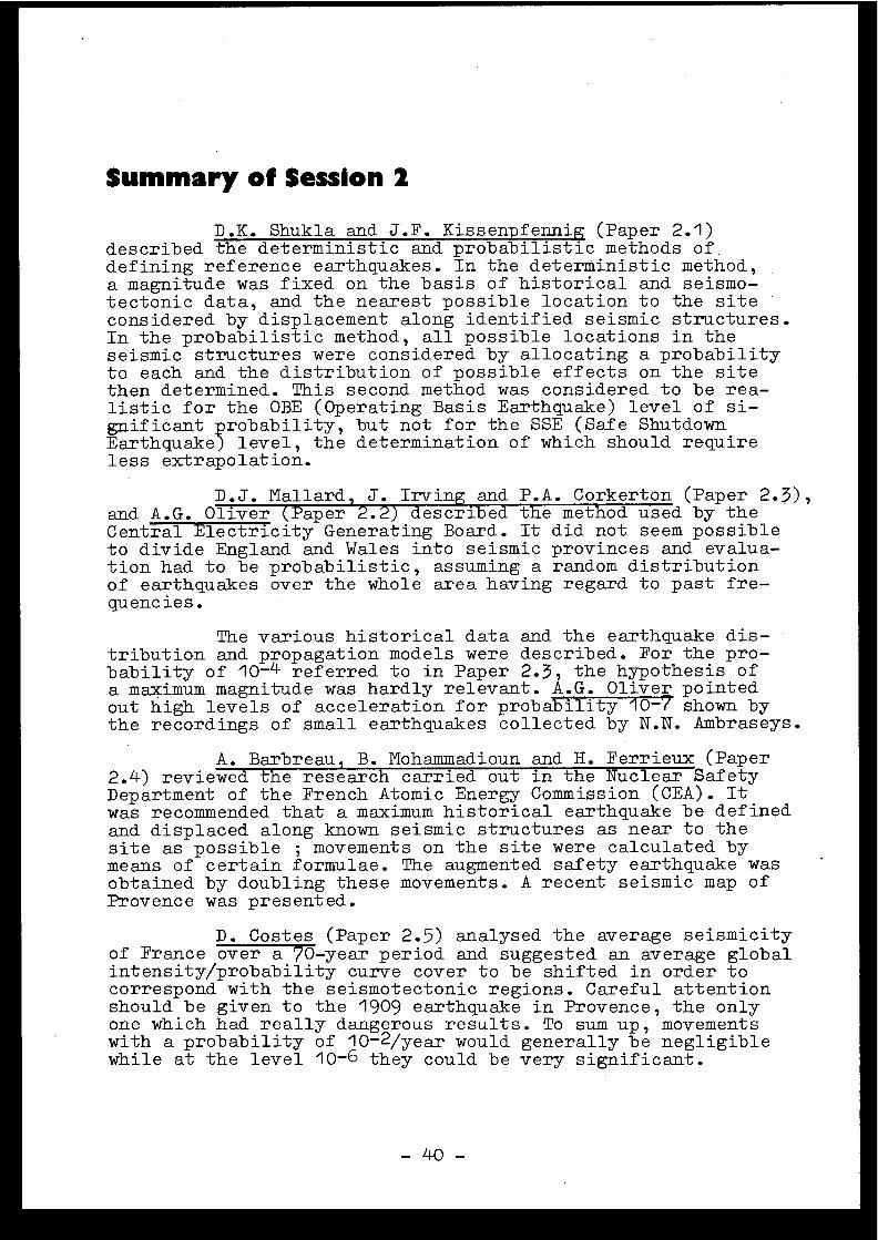
Summary of Session 2
D .K. Shukla andJ .F .Kissenpfennig (Paper 2 .1 )described the deterministic and probabilistic methods of .defining reference earthquakes . In the deterministic method ,a magnitude was fixed on the basis of historical and seismo-tectonic data, and the nearest possible location to the sit econsidered by displacement along identified seismic structures .In the probabilistic method, all possible locations in th eseismic structures were considered by allocating a probabilityto each and the distribution of possible effects on the sit ethen determined . This second method was considered to be rea -listic for the OBE (Operating Basis Earthquake) level of si-gnificant probability, but not for the SSE (Safe ShutdownEarthquake) level, the determination of which should requir eless extrapolation .
D .J . Mallard, J . Irving and P .A. Corkerton (Paper 2 .3) ,and A .G . Oliver (Paper 2 .2) described the method used by th eCentral Electricity Generating Board . It did not seem possibl eto divide England and Wales into seismic provinces and evalua-tion had to be probabilistic, assuming a random distributio nof earthquakes over the whole area having regard to past fre-quencies .
The various historical data and the earthquake dis-tribution and propagation models were described . For the pro-bability of 10-4 referred to in Paper 2 .3, the hypothesis o fa maximum magnitude was hardly relevant . A .G . Oliver pointedout high levels of acceleration for probability 10-7 shown bythe recordings of small earthquakes collected by N .N. Ambraseys .
A . Barbreau, B . Mohammadioun and H . Ferrieux (Pape r2.4) reviewed the research carried out in the Nuclear Safet yDepartment of the French Atomic Energy Commission (CEA) . Itwas recommended that a maximum historical earthquake be define dand displaced along known seismic structures as near to th esite as possible ; movements on the site were calculated bymeans of certain formulae . The augmented safety earthquake wasobtained by doubling these movements . A recent seismic map o fProvence was presented .
D .Costes (Paper 2 .5) analysed the average seismicityof France over a 70-year period and suggested an average globalintensity/probability curve cover to be shifted in order t ocorrespond with the seismotectonic regions . Careful attentionshould be given to the 1909 earthquake in Provence, the onlyone which had really dangerous results . To sum up, movement swith a probability of 10 -2/year would generally be negligibl ewhile at the level 10- 6 they could be very significant .
- 40 -
During the discussion, J .P . Rothé expressed reserva-tions about the validity of an evaluation covering the wholeof France and stressed that the seismic data used had probabl ybeen overestimated . H. Shibata introduced the idea of an"effective acceleration" comparable with an intensity, whic hwas considerably different from the real acceleration for shortmovements ; then again, intense earthquakes could have an ori -gin different from weak earthquakes and hence not be amenabl eto the same statistical treatment .
C . Weber pointed out that seismic zones could migrat eor become quiescent ,ent, and statistics over a long period wer etherefore necessary .
N .N . Ambraseys, reminded the meeting that 800 recor-ders had been installed in Europe and the Near-East since 196 2and had provided 200 recorded events at magnitudes of 3 to 6 . 5with epicentre distances of between 5 and 30 km. Peaks of highacceleration and high frequency were commonly observed (at 5to 10 Hz) although without any clear correlation between acce -leration and destruction. It appeared that the effects due t othe types of foundation and surface strata were substantial .N .N. Ambraseys recommended that structural calculations be din ein terms of time rather than using spectral methods in order t otake account of the effects of signal peculiarities and wave-length .
J .P . Rothé thought that. the idea of tackling problem sin a more general way should not be abandoned . With regard toprobabilities, he referred to the problem caused in the Unite dStates by the serious, isolated earthquake at Charleston .
There was a'general discussion of seismic maps . Adistinction could be drawn between analytical seismotectoni cmaps and probability maps for the use of the engineer, drawnup for example using the method described in Paper 2 .1 . Thes emaps existed in Japan and were being prepared in the followingcountries : Canada, Italy, F .R . of Germany and Switzerland . InFrance it was planned to do substantial work on analytical maps ;overall maps would be used to give initial information subjec tto a more accurate analysis for each site .
The meeting then went on to discuss the validity o fextrapolation to rare events . J . Despeyroux referred to thework done by the joint Committee on structural safety problems ,set up by a number of international associations . This Committe ewas tending to adopt "Extreme Type II" distribution laws fo rground accelerations ; seismologists would have to enlighte nconstructors about the applicability of this kind of law .
E . Robert pointed out that evaluations of rare event swere most unreliable . H . Shibata recalled that the deterministi cidea of maximum magnitude could be confirmed by critical argu -ments.D . Costes suggested that the quantitative study of safet ycould be based upon two earthquake levels at probability value sless than 10-2 per year (which did not affect France), so a s
- 41 -

better to assess the consequences of probabilities of plantrupture at various incident levels .
The salient points made may be summarised as follows :
- All countries were interested in probability evalua -tions which were sometimes the only ones possible ,but the deterministic evaluation of the SSE leve lstill had numerous supporters .
- The SSE leve was often related to the probabilityvalue of 10- per year, implying that at the corres -ponding excitation, the probability of plant ruptur ewas very low, if an overall rupture probability o fthe order of 10-6 to 10-7 was to be retained .
- There was not generally recognised logical relation -ship between the SSE and the OBE levels which wouldbe valid for all countries .
- The maximum ground acceleration was a most unsuitabl eparameter for describing an earthquake movement ; itwould be better to retain the concept of intensity ,subject to a more precise definition .
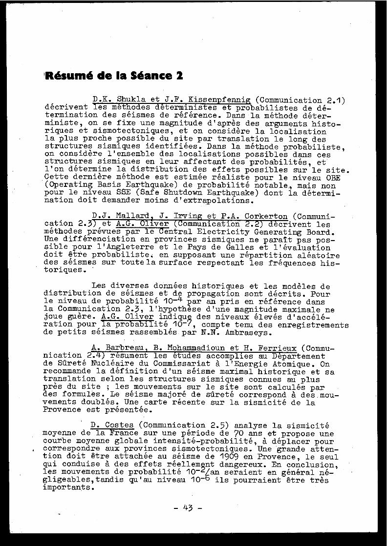
'Résumé de la Séance 2
D .K. Shukla et J .F . Kissenpfennig (Communication 2 .1 )décrivent les méthodes déterministes et probabilistes de dé -termination des séismes de référence . Dans la méthode déter-ministe, on se fixe une magnitude d'après des arguments histo -riques et sismotectoniques, et on considère la localisatio nla plus proche possible du site par translation le long de sstructures sismiques identifiées . Dans la méthode probabiliste ,on considère l'ensemble des localisations possibles dans ce sstructures sismiques en leur affectant des probabilités, e tl'on détermine la distribution des effets possibles sur le site .Cette dernière méthode est estimée réaliste pour le niveau OBE(Operating Basis Earthquake) de probabilité notable ., mais no npour le niveau SSE (Safe Shutdown Earthquake) dont la détermi -nation doit demander moins d'extrapolations .
D .J . Mallard ? J . Irving et P .A . Corkerton (Communi-cation 2 .3) et A .G . Oliver (Communication 2 .2) décrivent le sméthodes prévues par le Central Electricity Generating Board .Une différenciation en provinces sismiques ne paraît pas pos-sible pour l'Angleterre et le Pays de Galles et l'évaluatio ndoit être probabiliste ; en supposant une répartition aléatoiredes séismes sur toute la surface respectant les fréquences his -toriques .
Les diverses données historiques et les modèles d edistribution de séismes et de propagation sont décrits . Pourle niveau de probabilité 10-4 1)ar an pris en référence dansla Communication 2.3, l'hypothese d'une magnitude maximale n ejoue guère . A .G . Oliver indiqu des niveaux élevés d'accélé-ration pour la probabilité 10-(, compte tenu des enregistrement sde petits séismes rassemblés par N .N . Ambraseys .
A . Barbreau, B . Mohammadioun et H. Ferrieux (Commu-nication 2.4) résument les études accomplies au Départemen tde Sûreté Nucléaire du Commissariat à l'Energie Atomique . Onrecommande la définition d'un séisme maximal historique et s atranslation selon les structures sismiques connues au plu sprès du site ; les mouvements sur le site sont calculés pardes formules . Le séisme majoré de sûreté correspond à des mou-vements doublés . Une carte récente sur la sismicité de l aProvence est présentée .
D . Costes (Communication 2 .5) analyse la sismicit émoyenne de la France sur une période de 70 ans et propose un ecourbe moyenne globale intensité-probabilité, à déplacer pou rcorrespondre aux provinces sismotectoniques . Une grande atten-tion doit être attachée au séisme de 1909 en Provence, le seulqui conduise à des effets réellemnt dangereux. En conclusion ,les mouvements de probabilité 10-/an seraient en général né -gligeables,tandis qu'au niveau 10 -6 ils pourraient être trèsimportants .
-43-
En discussion, J .P . Rothé exprime des réserves su rla validité d'une évaluation globale pour la France et souli -gne que les données sismiques utilisées ont été probablemen tsurévaluées . H. Shibata donne la notion d'une " accélérationeffective" à rapprocher d'une intensité et très différente d el'accélération vraie pour les mouvements courts ; d'autrepart, les séismes forts peuvent avoir une origine différent edes séismes faibles et ne pas rentrer dans la même statistique .
C .Weber note les possibilités de migration et d equiescence de zones sismiques, ce qui nécessite des statisti -ques sur une longue d'urée .
N .N . Ambrase y s rappelle que 800 enregistreurs ontété installés depuis 1962 en Europe et au Proche-Orient et on tfourni 200 enregistrements, correspondant à des magnitude sde 3 à 6,5 et à des distances épicentrales de 5 à 30 km . Onobserve très généralement l'apparition de pointes à haut eaccélération et haute fréquence (5 à 10 Hz) sans corrélationnette entre l'accélération et la destruction . Les effets du saux types de fondation et aux couches superficielles parais -sent importants . Pour bien prendre en compte les effets lié saux particularités du signal et aux longueurs d'onde ,N.N. Ambraseys recommande de calculer les structures en des-cription temporelle plutôt que par des méthodes spectrales .
J .P . Rothé estime qu'on ne doit pas renoncer àtraiter les problèmes de manière plus générale . Sur les pro-babilités, il mentionne le problème posé aux Etats-Unis pa rle séisme grave et isolé de Charleston .
La discussion générale s'établit sur les carte ssismiques . On peut distinguer les cartes sismotectonique sexplicatives et les cartes de probabilités à l'usage de l'in-génieur, par exemple selon la méthode décrite dans la Commu-nication 2 .1 . Ces cartes existent au Japon et sont entreprise sdans les pays suivants : Canada, Italie, République fédéral ed'Allemagne, Suisse . En France, un travail important est pré -vu, comportant des cartes explicatives . Les cartes générale sseraient utilisées en première indication, sous réserve d ' uneanalyse plus précise site par site .
On discute ensuite la validité des extrapolation saux événements rares . J . Despeyroux note les travaux du Comit émixte sur les problèmes de securité structurale, Comité fond épar diverses associations internationales . Ce Comité tend àadopter des lois de distribution "Extrême Type II" pour le saccélérations du sol ; des sismologues devraient renseigne rles constructeurs sur la validité de telles lois .
E . Robert attire l'attention sur la faible confianc eà accorder aux évaluations d'événements rares . H . Shibat arappelle que la notion déterministe de magnitude maximal epourrait être confirmée par des arguments physiques . D . Coste ssuggère que l'étude quantitative de sûreté pourrait être fon-dée sur deux niveaux de séismes à des niveaux de probabilit é
44

plus faibles que 10- 2 par an (qui n'a pas d'incidence enFrance), de manière à mieux apprécier l'effet des probabilitésconditionnelles de rupture de l'installation à divers niveauxd'agression .
résumées :
- On s'intéresse dans tous les pays aux évaluation sprobabilistes, parfois les seules possibles, mai sl'évaluation déterministe du niveau SSE garde d enombreux partisans .
- Le niveau SSE est souvent relié à la probabilité 10-4par an, ce qui implique que sous l'excitation corres -pondante, la probabilité de rupture de l'installatio nsoit très faible, si l'on veut garder une pRobabilit églobale de rupture de l'ordre de 10-6 à IO-7 .
- On ne reconnaît pas en général de relation logiqu eentre les niveaux SSE et OBE, qui serait valable pourl'ensemble des pays .
- L'accélération maximale de sol est un paramètre trè simpropre pour décrire un mouvement sismique ; mieuxvaudrait garder l'intensité, en précisant cette no-tion .
Les principales idées exprimées peuvent être ainsi
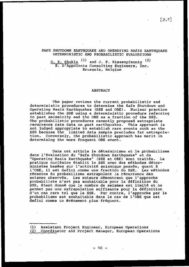
SAFE SHUTDOWN EARTHQUAKE AND OPERATING BASIS EARTHQUAK EDETERMINISTIC AND PROBABILISTIC EVALUATION S
D . K . Shukla (1) and J . F . Kissenpfennig (2 )E . D'Appolonia Consulting Engineers, Inc .
Brussels, Belgium
ABSTRACT
The paper reviews the current probabilistic an ddeterministic procedures to determine the Safe Shutdown an dOperating Basis Earthquakes (SSE and OBE) . Nuclear practic eestablishes the SSE using a deterministic procedure referrin gto past seismicity and the OBE as a fraction of the SSE .The probabilistic procedures recently proposed extrapolat erecurrence rate data on past earthquakes . This approach isnot judged appropriate to establish rare events such as th eSSE because the limited data sample precludes far extrapola -tion . Conversely, the probabilistic approach has merit indetermining the more frequent OBE event .
Dans cet article le déterminisme et le probabilism edans l'évaluation du "Safe Shutdown Earthquake" et d u"Operating Basis Earthquake" (SSE et OBE) sont traités . Lapratique nucléaire établit le SSE avec des méthodes déter -ministes basées sur l'activité seismique passée, quant àl'OBE, il est defini comme une fraction du SSE . Les méthodesrécentes du probabilisme extrapolent la récurrence de sseismes observés . Les auteurs démontrent que l'approch eprobabiliste n'est pas souhaitable pour la définition duSSE, étant donné que le nombre de seismes est limité et n epermet pas une extrapolation suffisante pour la définitio nd'un cas rare tel que le SSE . Par contre, l'approche par leprobabilisme est souhaitable dans le cas de l'OBE que es tdefini comme un événement plus fréquent .
(1) Assistant Project Engineer, European Operation s(2) Coordinator and Project Manager, European Operation s
- 46 -
1 .0 IntroductionSeismic loads for nuclear power plants (NPP) ofte n
govern design and therefore the determination of basi cdesign seismic inputs represents a fundamentally significan taspect of NPP design . The design input motion is widel ytermed as the Safe Shutdown Earthquake (SSE) . The UnitedStates Nuclear Regulatory Commission (USNRC) provides th efollowing definition (1 )
"The Safe Shutdown Earthquake is that earthquakewhich is based upon an evaluation of the maximu mpotential considering the regional and local geolog yand seismology and specific characteristics of loca lsubsurface material . . . . "
It is distinguished from the lower level Operating Basi sEarthquake (OBE) by the USNRC as follows :
"The Operating Basis Earthquake is that earthquake ,which, considering the regional and local geology an dseismology and specific characteristics of local sub -surface material, could reasonably be expected t oaffect the plant site during the operating life of th eplant ; . . . "
The current practice requires that a plant experi -encing an OBE should be shutdown for complete inspection .The plant structure is designed to remain elastic during a nOBE, whereas yield stress are used for an SSE design .
Current procedures for SSE evaluation are generall ybased upon "deterministic" concepts which account for theworst estimated seismic effects at the site in the recorde dhistory (1) . This approach is considered present State-of-the-Art and is briefly reviewed in Section 2 .0 . Anotherapproach proposed in recent literature (2,3,4) evaluates th eproblem using "probabilistic" theory and determines the SSEas a very rare event, as discussed in Sections 3 .0 and 4 .0 .Finally, Section 5 .0 evaluates merits and drawbacks of bothapproaches in determination of the SSE and OBE at nuclea rpower sites . The paper concludes that a deterministicapproach is required for definition of the SSE ; while probabi-listic considerations have merit for establishment of th eOBE .
2 .0 Step-by-Step Procedure for Establishing the SSE and OBE-Deterministic Approach
Utilizing the above definitions and following th esteps of the USNRC Appendix A to 10 CFR 100, the followin gstep-by-step procedure has evolved (5,6,7) .
1 . Review and summarize the basic geology and tectonic sof the region of the site (200 miles or 320 kilo -meters radius) with particular attention paid t omapped faults and the boundaries of the seismotectoni cprovinces . A tectonic province is defined by the USNRC
-47-
and International Atomic Energy Agency as a regio ncharacterized by a relative consistency of the geologi cstructural features contained therein (1,5) .
2. Conduct a review of the seismic history of the regio nincluding offshore areas ; locate the epicenter sof all major earthquakes .
3. Relate these epicenters to mapped faults And/o rseismotectonic provinces defined in Step 1 .
4. Based on the results of Step 3, postulate a group o fconceivable SSE's by selecting the most severe earth -quake along each fault ; or in each seismotectonicprovince, and move these earthquakes to the point alon gthe fault, or within the seismotectonic province, tha tis closest to the site .
5. Develop a set of attenuation curves applicable t othe region of the site .
6. Using the attenuation curves from Step 5 and th egroup of conceivable SSE's from Step 4, along wit hthe minimum distances to the site., determine thesite Intensity and classify this as the site SSE .
7. Through accepted correlations between Intensity andpeak ground acceleration, establish the peak groundacceleration that corresponds to the SSE for the site (8) .
8. Select the OBE as an earthquake with peak ground accel-eration equal to at least one-half the SSE .
With minor exceptions, this process is generall yused at most reactor sites in the Western World . For site swhere Magnitudes are available, a similar approach may beadopted by making use of acceleration versus epicentra ldistance attenuation curves (9) .
3 .0 Step-by-Step Procedure for Establishing the SSE andOBE - ProbabilisticApproach
An alternate to the deterministic approach, i sbased on probabilistic concepts . While the regulatoryaspects of the probabilistic approach are not clear (1,5) ,the probabilistic approach, nevertheless, may provide theengineer, the seismologist and the regulatory group wit hadditional quantitative insight into the safety aspects o fthe plant design . Essentially this approach estimates th erate of recurrence at the site of seismic events, and the nthe SSE or OBE is selected with a predetermined designrecurrence rate .
The analysis rests mainly on two assumptions .First, the seismic activity within any seismotectonic provinc eor along known major faults with characteristic seismicit yis uniformly distributed . Secondly, the recurrence rate sfor earthquakes of a given Intensity in any seismotectoni cprovince is assumed to remain the same as observed in thepast. Regarding the first assumption, it is noted that an yone seismotectonic province has a unit of geologic structureand equipotential seismicity . With regard to the secondassumption, a review of the number of damaging events in th esite region over the past few hundred years needs to b e
-48-
made . Generally speaking, since the projected life of a NP Pis very small with respect to geologic, or even histori ctime, one may reasonably expect this assumption to be valid .
The following steps briefly describe the genera lapproach used in the probabilistic determination of SSE o rOBE .
1. The boundaries of the seismotectonic province sare determined within a 320 kilometer radius of th esite and known major faults with characteristic seismi chistory are defined .
2. Each contributory area is divided into a gri dof small elements for purposes of numerical integra -tion . Similarly, the significant faults in the con-tributory area are divided into linear source elements .The area or length of an element, j, is denoted as Aj ,and its distance from the site is denoted as Rj . Theseismic activity in each small element is assumed tooriginate at its geometrical center .
3. The recurrence rates for earthquakes are established b ythe well known empirical recurrence relationship (10 )given as :
log(N) = ak + bk I
(1 )
where N is the number of earthquakes per unit area (o rlength per year of Intensity I, or greater ; I is theIntensity on the Modified Mercalli Scale ; k denotes theseismotectonic province or fault ; and a(k) and b(k) areconstants characteristic of the earthquake recurrenc erate for the provinces or faults .
4. For each element, j, in each seismotectonic provinc ethe seismic activity per year is computed in smal lIntensity increments of the order of 0 .2, using therecurrence relationship given by Eqn 1 . Thus, thenumber of earthquakes per year in element j, betwee nIntensity I-0 .1 and I+0 .1 denoted here as nj is obtaine das :
nj (I-0 .1< I< I+0 .1)=Aj ( 10 (ak+bk (I-0 .1))_ 1O (ak+bk (I+O .1) )
(2 )
5. Due to attenuation of the earthquake ground motion, th eground at the site experiences a lower Intensity tha nthe epicentral area . Thus, an earthquake of Intensity Iwith its epicenter in the element j, causes an earthquak eof Intensity Is at the site, where Is may be estimate dby using regional attenuation curves .
6. The seismic activity between Intensities I-0 .1 andI+0 .1 in the element j causes nj (1-0 .1< I< 1+0 .1 )earthquakes of Intensity Is at the site . The contribu-tions from all the elements are computed and summed ,which in turn yields the seismic activity distributio nfor the site . From this, one derives the expecte dnumber of earthquakes per year at the site wit h
L 9
Intensity Is or greater, N(Is) . The expected returnperiod, denoted as Rp(I) of an earthquake with Inten -sity I or greater is obtained as :
RP( I ) = 1/N (I)
(3 )
7. The earthquake with design return period, i .e . approxi-mately the inverse of the probability of occurrence peryear, is chosen as the SSE . Similarly an earthquak ewith return period one to two times the life of theplant could be chosen as OBE .
8. The acceleration corresponding to the SSE or OBE Intensit yis determined, using accepted acceleration Intensit yrelationships (8) .
If sufficient earthquake Magnitude data are available ,the recurrence relationships in Step 3 are represented i nterms of Magnitude, and the attenuation curves (9) the ndirectly predict the postulated acceleration at the site ,and Step 8 is not needed .
4 .0 Discussion of Input Parameter sSeveral critical inputs to the probabilistic approac h
have not yet been established thoroughly . Specifically ,the following points deserve careful consideration :
(1) Earthquake recurrence rate versus Intensity relationships .(2) Maximum Intensity earthquake to be considered in the
analysis .(3) Choice of recurrence period for the SSE/OBE .(4) Interpretation of seismic activity distribution i n
the near vicinity of the site .
4 .1 Recurrence Rate Versus Intensity Relationship sAs discussed above and illustrated on Figure 1 ,
relationships between the logarithm of recurrence rate an dIntensity are usually represented as a straight line . Therecurrence data for medium Intensity earthquakes (sa yIntensity V, VI, VII, VIII and sometimes IX) are plotted an da straight line is fitted through them .
The procedure seems justifiable, but in general i thas been observed (11) that it over-predicts the recurrenc erate for high Intensity earthquakes . For example, in agiven region, no earthquake of Intensity higher than VII ma yhave been observed in the past 100 years and none highe rthan VIII may have been observed in the past 2000 years ;whereas, the recurrence curves extrapolated from 50 yeardata may predict the recurrence rate of four or five IIntensity X earthquake per 1000 years .
Based upon the observed data, some researchers (11 )have proposed that a quadratic relation (curve 2 on Figure 1 )be adopted, such that the recurrence rate decreases morerapidly with increasing Intensity . In the authors opinion ,
- 50 -
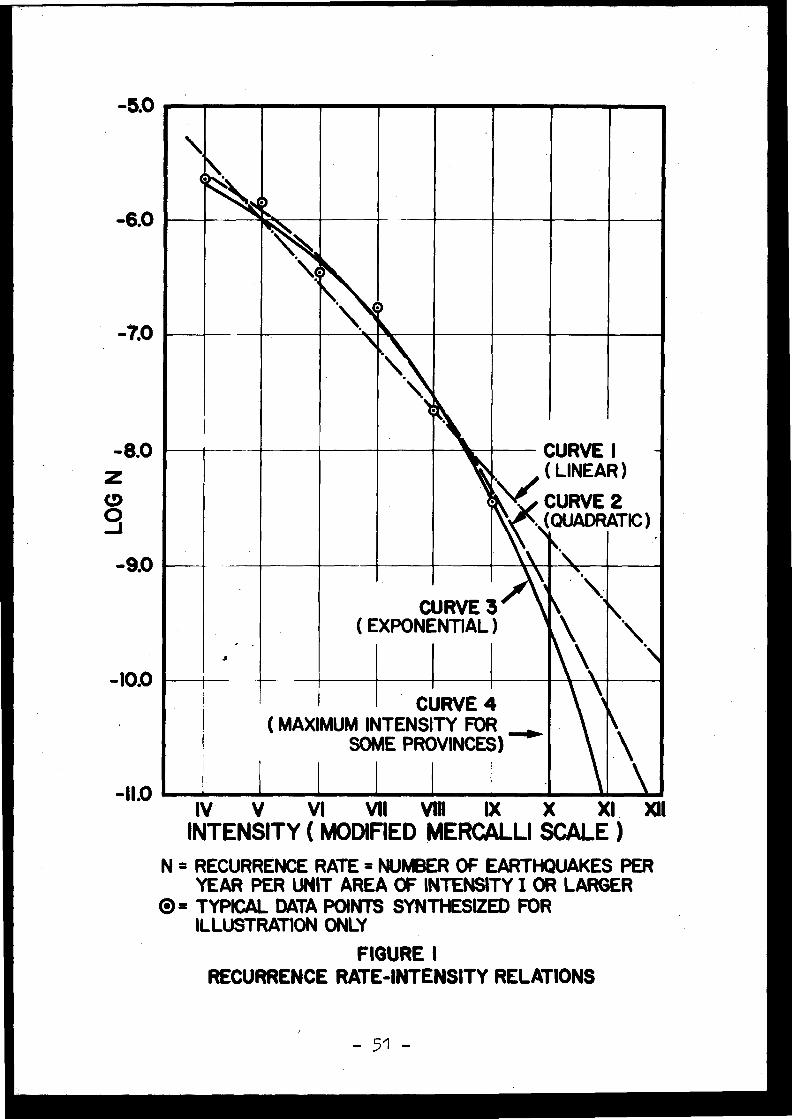
CURVE I\
(LINEARY CURVE 2
(QUADRATIC )
CURVE 4( MAXIMUM INTENSITY FOR
SOME PROVINCES )
-5.0
-6.0
-7.0
-8.0ZÔJ-9.0
-10.0
-I1.0 IV
V
VI
VII
VIII
IX
X
XI, XIIINTENSITY ( MODIFIED MERCALLI SCALE )
N = RECURRENCE RATE = NUMBER OF EARTHQUAKES PE RYEAR PER UNIT AREA OF INTENSITY I OR LARGE R
O = TYPICAL DATA POINTS SYNTHESIZED FO RILLUSTRATION ONLY
FIGURE IRECURRENCE RATE-INTENSITY RELATIONS
- 51 -
an exponential or extreme value type relationship (curve 3of Figure 1) should be adopted, thereby predicting a limitingrecurrence rate of zero (or logarithm of recurrence rate tominus infinity) for earthquakes with highest postulatedIntensities . Another justification for adopting quadrati cor exponential type recurrence rate curves is also providedby the observation that historical records for low Intensityearthquakes tend to be incomplete as documented by Stepp (12) .Ultimately, the authors feel that Bayesian theory should beused to evaluate the significance of all the proposed curve sand their associated SSE-OBE's .
4 .2 Maximum Intensity Earthquake on each ProvinceBy definition, the maximum Intensity of the Modified
Mercalli Intensity Scale is XII . However, as discussed witha few examples in the last section, a maximum Intensity o fonly VIII may have been observed in a region within the pas t2000 years, whereas the recurrence rate curves may pre cict' ahigh recurrence rate of significantly larger earthquakes .To avoid this obvious inconsistency between the observedhistorical data and the predicted recurrence rates, theauthors recommend that within a given tectonic province o rfault, a maximum Intensity of two degrees higher than th emaximum observed Intensity in that province or fault beadopted for probabilistic computation (curve 4 on Figure 1) .Using Magnitude data, the world-wide upper bound near M= 9appears appropriate and, within any province, the author srecommend a maximum Magnitude of one unit larger than themaximum Magnitude observed .
4 .3 Choice of Recurrence Period for the Basis of the SSE and OBEDiscussions with professionals and regulatory
groups indicate that a recurrence period varying betwee n1,000 and 10,000 years appears adequate for SSE determinatio nin NPP design . A check on the SSE for a few sites, derivedusing the widely accepted deterministic procedures describe dabove, seems to verify this opinion . The recent USNRCRasmussen Report (13) or WASH-1400, also indicates that a nearthquake with a 10,000 year recurrence will be sufficientl yconservative for SSE determination in NPP design . The OBEis selected as amore frequent, lower level earthquake . TheUSNRC definition (1) of OBE suggests that this event coul dbe expected in the lifetime of the plant and therefore areturn period of 50 to 100 years is appropriate .
4 .4 Seismic Activity Distribution Near Sit eFor high Intensity SSE values, the greatest contribu-
tion to the site SSE is generally provided by the seismi cactivity in the area within approximately 25 to 50 kilometersfrom the site . Since these nearby earthquakes are of grea tinterest as potential SSE values, it is important that th econtributory area near the site be carefully subdivided int oan elemental grid (see Step 2 in Section 3 .1) . The siteitself should be assigned to the center of an area whos eradius will equal the distance for zero attenuation ; i .e .the site element represents the minimum area of zero attenuation .
- 52 -
If the analyses uses a large site element where the radiu sis larger than the zero attenuation distance, an overl yconservative event will be derived, since the local seismi cactivity will be artificially concentrated at the sit ewithout any attenuation . Similarly, a too small site elementwill result in an unconservative value. Generally speaking ,a ten kilometer seismic contributory element should b eassigned to the site, leading to aminimum zero attentuaio ndistance of about 5 kilometers . The element size could beincreased as the distance from the site increases .
5 .0 Discussion of the Two Procedure sWhereas, the deterministic approach is based upo n
the most intense earthquakes observed, the probabilisti capproach is based upon the numerical count of various Inten -sity earthquakes . The available historical data for Intensi -ties lower than say MMI VI is usually incomplete and th enumber of high intensity earthquakes observed is usually no tstatistically sufficient, and thus the final results for arare event such as SSE are chosen using a substantial amount .of engineering judgement and interpretation ; thereby losingthe apparent exact "quantification" of seismic data . However ,the probabilistic approach seems more meaningful for OBE ,since this event is more frequent . Further, since thecurrent USNRC regulations specify lower damping and allowabl estress for OBE analysis than for SSE analysis, and the load scombined with OBE are more stringent, it is the OBE whichsometimes governs the final design of some components o fnuclear power plants (15) . For this additional reason, theOBE should be determined with more care using probabilisti cprocedures, independently of the deterministic SSE . Incident-ly, the authors experience indicates that these more detaile dstudies will lead to OBE values smaller than the classica l0 .5 SSE value .
6 .0 Summary and ConclusionsThis paper has summarized the present State-of -
the-Art procedures for establishing the basic seismic desig ncriteria for nuclear power plants ; the procedures use adeterministic approach for the SSE and a probabilisti capproach for the OBE . In the authors opinion, a deter-ministic procedure for the SSE has the following advantages :
(1) Heavy reliance is placed on regional and local geology ,tectonics and seismicity
(2) The end product depends more on the quality of thedata, rather than the quantity of the sample of data .
(3) The procedure in itself is logical, reflects theworst events observed, and can be verified and understoodwith ease by the Applicant and . the Regulatory Groups .
The probabilistic - statistical approach has als obeen illustrated . This procedure may, at first, appear moreattractive since it could provide a quantitative insigh tinto the safety aspects of nuclear power plant design .However, the following pitfalls need to be considered :
-53-
(1) The procedure may lack an adequate sample of dataand an adequate model of physical mechanisms . Thebasic philosophy of extrapolating 50 to 200 years ofstatistically significant earthquake data to predic trare 1000 to 10,000 year SSE events is consideredinadequate .
(2) The mathematical procedure is quite complex and on emay easily lose touch with the actual subject andartificially extract more information than exists i nthe source material .
In summary, the authors believe that the extrapola -tion of earthquake data should be limited to recurrenc eperiods within one order of magnitude of the period fo rwhich statistically significant earthquake data are available .Accordingly, probabilistic determinations of SSE should b eused with extreme caution and primary emphasis should stil lbe placed on geology and historical seismicity . On theother hand, the OBE could be primarily determined from th eprobabilistic analyses, since the OBE recurrence perio dcompares with the period for which a reasonably complet esample of data is available .
54

LIST OFREFERENCES
1. Part 50 - Licensing of Production and Utilizatio nFacilities, and Part 100 - Reactor Site Criteria, FederalRegister, Vol . 38, No . 218 , , United States Atomic EnergyCommission, Washington, D .C . November 13, 1973 .
2. Algermissen S .I ., and D .M . Perkins, A Technique forSeismic Zoning, General Consideration and Parameters ,NOAA Techinical Report No . ERL267-ESL30, Contributio nto Seismic Zoning, May, 1973 .
3. Cornell, A .C . and E .H .0 Vanmarcke, The Major Influenceon Seismic Risk, Fourth World Conference on EarthquakeEngineering, Santiago, Chili, Vol . 1, pp 69-83, 1969 .
4. Esteva, L ., Seismic Risk and Seismic Design Decision ,edited by R .J . Hansen, M .I .T . Press, 1970 .
5. International Atomic Energy Agency, Earthquake Guidelinesfor Reactor Siting, Technical REports Series No . 139 ,Vienna, Austria, 1972 .
6. Rizzo, P .C ., Seismologic/Geologic Criteria andConsiderations for Siting Surface and Underground Nuclea rPlants, Antiseismic Design of Nuclear Power Plant ,Pisa, Italy, October 3-5, 1972 .
7. Iansiti, E . and E . Iaccarino (CNEN-Divisione Sicu Rezza eControlli - Rome) ., The Definition of Design Basi sEarthquake, Antisiemic Design of Nuclear Power Plants ,Pisa, Italy, October 3-5, 1972 .
8. Neumann, F ., Earthquake Intensity and Related Groun dMotion, University of Washington Press, Seattle ,Washington, 1954 .
9. Schnabel, P .B ., and H .B . Seed, "Accelerations in Rock fo rEarthquakes in the Western United States," Bulletin ofthe Seismological Society of America, Vol . 63, No . 2, 1973 .
10. Guternberg, R . and C .F . Richter, Earthquake MagnitudeIntensity, Energy and Acceleration, BA, No . 46 ,pp 105-145, 1956 .
11.. Cornell, C .A . and M .A . Merz, Seismic Risk Analysis Basedon a Quadradtic Magnitude-Frequency Law, BSSA, Vol . 63 ,No . 6, December 1973 .
12. Stepp, J .C ., Analysis of Completeness of the Earthquak eSample in the Puget Sound Area and its Effects o nStatistical Estimates of Earthquake Hazard, Proc . of theInternational Conference on Microzonation for Safet Earth -Construction, Research and Application, Seattle ,Washington, pp .897-909, Vol . II, 1972 .
13. Reactor Safety Study, and Assessment of Accident Risk sU .S . Commercial Nuclear Power Plants, United State sAtomic Energy Commission, WASH-1400, August, 1974 .
14. Freudenthal, M ., Structural Safety, Reliability and Ris kAssessment, School of Engineering and Applied Science, Th eGeorge Washington University, Washington D .C ., TechnicalReport No . 20, May, 1974 .
15. Stevenson, J .D ., "Rational Determination of the Operationa lBasis Earthquake and Its Impact on Overall Safety and Cos tof Nuclear Facilities," Paper Kl/ll, Proceedings of theThird SMIRT Conference, London, September, 1975 .
-55-

Discussions
J .P . ROTHE, France
Quelle est l'unité que vous utilisez dans la formul eSSE = 2 OBE ?
D .K . SHUKLA, United State s
Peak ground accelerations, the SSE acceleration an dthe OBE acceleration . Well, that number I put, as you noted ,with a wiggle ; that's another parameter we will have to define .
[2.2]
A METHOD OF DERIVING REFERENCE GROUND
MOTIONS FOR ENGLAND AND WALES
A . G . Oliver
Generation Development and Construction Division ,
Central Electricity Generating Board ,
Gloucester, England .
Paper presented by J . Irving
This paper describes how consideration of extreme external hazards t osodium cooled fast reactors to be installed in a region of low seismicit yled to a nee to predict earthquake ground motions down to a probabilit ylevel of 10 or less per year .
It puts forward and discusses a method for deriving probabilities o fground motions from an assessment of the frequency of earthquakes in th eregion concerned, together with strong ground motion data from overseas .
A frequency curve for ground acceleration and a spectral respons eenvelope illustrate . applications of the method to England and Wales .
Introduction
The vulnerability of sodium-cooled fast reactors to dynamic ground motionswas examined at the beginning of 1973 as part of an overall consideratio nof extreme -external hazards . Events having probabilities of occurrenc edown to 10 per year or more were being considered if they could cause aserious release of radioactivity from reactors in the anticipated prog -ramme . No suitably detailed study of the seismicity of England and Wale swas available . That area was covered, however, as Region 10b inV . Karnik's "Seismicity of the European Area" . It indicated for the years1 80 1 -1 955 a maximum intensity of VII (MSK), a mean focal depth of 15-20K mand various maximum Magnitudes up to M = 6 .0 .
Seismic Source s
In addition to earthquakes, the initial appreciation identified othe rpotential sources of significant seismic motions in peace time . Theseinclude :
Blasting operations for later stations on the same site and thei rassociated explosives stores ,
A reactor explosion at a twin-reactor station ,
Military/commercial explosive stores in the area and unexplodedbombs at site .
The appreciation also disclosed that for earthquakes, scaled intensitiesof ground motions were not a sufficient basis for quantitative assessmentof seismic hazard, nor were the then available characterisations of earth -quake ground motions validly applicable to the shallow nearby earthquake sseen as critical in England and Wales .
For the explosive sources, once their size and location has been identif-ied, ground motions can be quantified relatively easily . It is anticip -ated that any limits on ground motions at a station can be met by contro lof layout and operations, and by thorough investigation of the site an dits purlieu . The . investigations must also be relied on to disclose an yworkings or surficial geological features which could be a very nearseismic source . The reference ground motions should, then, be charact -eristic of the natural seismicity of the general area .
Seismicity of England and Wale s
As an electriciy undertaking, CEGB covers England and Wales, an area o fabout 150,000Km . Earthquakes of engineering significance are of infre -quent occurrence over that whole area . As individual events over th elast century, they mainly appear to have been subsequently related to well -established features of the geological structure . In many cases lesserseismic events have also been attributed to the same major structura lfeatures . However, it must be noted that the area is extremely well-offfor known faults . Put together, the larger macroseisms do not amount toa convincing sample in a statistical sense, nor when plotted do thei repicentres form a well defined pattern . There does not yet seem to be afirm basis for excluding the possibility of the largest future earth -quakes from occurring more or less anywhere in England and Wales .
- 58 -
Nevertheless if account is also taken of the smaller macroseisms, a cas ecould be made for zoning the area in terms of significantly differentprobabilities of a given size seismic event . Furthermore, it is recognise dthat it may be possible, and even worthwhile, to show from local seismi chistory and geology that a particular site will have significantly lowe rseismicity than the average for England and Wales .
UK seismic records from the year 1800 have been assembled on a compute rfile by the Global Seismology Unit of the Institute of Geological Sciences .It is preponderantly based on reports of felt intensity and observe ddamage. Quantitative expressions of that data contain one or more inter -pretation of the original quantitative evidence in light of contempor -aneous ideas as well as containing those implicit in the computer processe sThe instrumentally measured ground motions do not include any stron gground motion measurements . The rate of accession of teleseismic dat aon UK earthquakes of engineering significance is clearly limited by thei rinfrequent occurrence . Their sporadic occurrence dims the prospect o fobtaining measurements of typical strong ground motions in England an dWales . As the vindication for developing the sodium cooled fast reacto rwill lie in adopting it for the bulk of the future nuclear power prog -ramme, considerable advantage should accrue from adopting standar dstrong motions for the general run of the programme, which can be assume dto be sited on normal foundation conditions .
Method of Deriving Reference Ground Motions
The foregoing reasons led to attempts to derive reference ground motion sin a way which would draw on the body of seismic data relating toEngland and Wales as a whole and also be consistent with a generall yacceptable view of earthquakes and the main body of seismic data .Additionally, it was regarded as desirable to follow a probabilisti capproach . This was on the grounds of the extra illumination such a for mcan bring during the exercise of engineering judgment ; it was a reflectio nof a view on the proper basis for a safety policy .
One such approach is to base the probability on the chance of covering on epoint in a large area by ling down a small area a - at random over thelarge area A, i .e . 1 - e .
This can be extended to give the frequencyof a station being "hit" by a ground motion in excess of a particula rvalue by introducing the frequency of random earthquakes producing suc hground motions, together with the areas over which they occur . Categori -sing these events into sizes and denoting their size by magnitude, the na magnitude/frequency relationship and a magnitude/ground/distance rela -tionship will yield a probability distribution for ground motions .
Event Frequency
The correlation N = a ebM is proposed as the basis for the magnitude/frequency relationship, as it is well established for the more seismi cregions of the earth. Although correlations have been proposed betwee nranges of values for a and b and particular seismic characteristics o fthe zones it seems preferable to fit the correlation to what data i savailable for the area in question . In the case of England and Walesa fit made br the Institute of Geological Sciences provided values o fa = 2.7 x 10' b = 2.2. A well-recognised feature of this expression o f
- .59 -
seismicity is that the line falls off markedly at higher amplitudes ,implying-a practical limit to earthquake magnitude in a particular zonewhich can be less than the largest that have been recorded in the reall yactive seismic areas . The question of whether the correlation extrapolateswithout change to magnitudes well above the largest earthquakes recorde dfor the UK or whether there is an upper limit close to that largest earth -quake turns out to be crucial. While the data has been interpreted a spointing fairly strongly towards the latter proposition, there is n oimmediate prospect of an unconditional and generally supported recommenda-tion to that effect . Also there seems little prospect of deriving a usefulmaximum through placing geologically inferred limits on for example th esource parameters of a slip dislocation .
Earthquake Mode l
In order to derive a relationship between magnitude and surface groun dmotions for the randomly occurring future events under consideration, amodel is required . It should be the simplest that will fulfill the mainpurpose, not only for ease of application but also to minimise any con -fusion between complexity and validity . The selected model is of a trainof elastic waves radiating from a point source event . The shape of thewave train is determined by the mechanism, its amplitude by the magnitud eof the source event . The wave trains diminish in amplitude as a functionof distance from the source ; i .e . they are unaltered in shape . Forsurface points, then, the amplitude depends on the (focal) depth an depicentral distance . This model is recognisably inadequate for investiga -ting actual events . Also the model does not purport to cover localsurface conditions and interactions ; this paper is confined to consideringthe free field motions in solid ground .
Source Mechanis m
In view of the shallowness attributed to the larger seismic events i nEngland and Wales, they can be regarded as propagating slip dislocation sin the basement rocks. For predictive purposes then, the events ar etaken to have that focal mechanism . For some aspects of surface groundmotions, the events are not taken as point sources, e .g. using sense o ffirst motion to determine the fault plane direction or differentiat ebetween natural earthquakes and undistributed nuclear explosives . Formotions of engineering significance in regions of moderate seismicit ywhere large earthquakes are the source events, it does seem satisfactor yto regard them as point sources in view of the ratio between distance t othe source and source dimensions, the duration of the motions, the filter -ing effect of the intervening ground and the concentration on the respons easpects of the ground motions . By contrast, when analysing strong groun dmotion measurements from nearby shallow earthquakes or when predictin gthem from an identified source feature, the extended nature of the sourc ecannot be overlooked . The idealisation of such an event into a disloca-tion appearing at the focal point and extending symmetrically across atrue plane to produce a fault sling at constant Velocity within aregular boundary provides a model by which ground motions could be derive dfrom the geometrical parameters of the fault and the rupture and sli pvelocity by regarding each wall of the fault as a radiating extende dsource . With virtually no data on the parameters of UK events, it seem spointless to use even this simple model for predicting the ground motion s
- 60 -
in England and Wales . However, it is worth noting some of the implicationsof using the proposed point source model to obtain predictions from over-seas ground motion data . Relationships between vertical and horizontalcomponents of surface ground motions will depend on whether the slip an ddip angles of the faults are similar . The spectral shape of the motionsare strongly dependent on the rupture and slip velocities,which in turnare dependent on material properties and stress conditions . There is noclear understanding of the extent to which the seismicity of England an dWales is due to boundary tectonics of the European lithosphere plate o rto more local isostasy, e .g. whether thrust or steep dip slip faults arethe .main Modes .
Focal Depth
The geological model has the significant earthquakes occurring in th ePrecambrian basement rocks . Precambrian outcrops at the western edge o fthe area and al go at isolated locations . However, the base of the late rsedimentaries generalise to a depth of about 7Km . Estimates of the depthof earthquakes from the records place them mainly in a region from 74 t o15Km depth. For the predictive model a focal depth of 10Km was chosen .As well as being convenient, it corresponds to the largest expecte dearthquakes occurring as vertical equidimensional faults at the top o fthe basement rock .
Scaling for Magnitude
Application of the original definition of magnitude to the proposed pre- Mdictive model results in scaling ground motion amplitudes by the factor e .Also, wherever data have assigned values of magnitude they are taken a ttheir face value, regardless of the wave selected or magnitude scale used .The practical choice lies between doing that or else dealing thoroughl ywith all the discrepancies that may be concealed in a quoted magnitude ,i .e . not only differences between the frequencies, phases and correctiona lprocedures variously adopted but also instrumental errors and errors i nthe corrections applied for the station, for transmission behaviour an din location of the source . The nature of the model and validity of th emagnitude frequency relation for England and Wales hardly warrant the eff- .ort that would be needed to quantify the error introduced into a predic -tion from probable errors in individual values of magnitudes .
Scaling for Distanc e
Two sources were examined for a scaling factor for the predictive mode lto relate amplitudes of ground motions with focal distance - theoretica ltreatments of simple models and correlations obtained from detailed invest -igations of strong ground motions . For spherical body waves in a purelyelastic medium, compression ant shear waves show particle motions varyin gas radius nearby, as radius at a distance . Taking an acoustic dipoleto be analagous to radiations from the extended plane source of a propaga -ting slip mechanism, then ground motions should be inversel y-proportionalto distance in the far-field, but also dependen t , on distance in the nea rfield. Practical correlations include factors other than the geometrica lin homogenieties in material properties, layering and inelasticit4es suchas dissiption. These correlations tend to lie between distance an ddistance over the distances involved . Analyses of cylindrical body
- 61 -
waves show a distance- dependence . However, the predictive model isessentially for nearby earthquakes so this mode is rejected . Likewisepractical correlations covering distances much greater than the epicentra ldistances in the predictive model should not be drawn upon . 14e focaldistance (D) scaling factor should be confined to the range D to D .If conviction permits, a particular practical correlation may be uffed, o reven a correlation of correlations . Convenience suggests using D i nthe first instance, then D to indicate the spread involved. It has beennoted that predictions from the model are not particularly sensitive t othe distance scaling factor as the focal distances of the input data hav ebeen commensurate with those of significance to the prediction .
Parameters of Interest
Initially two aspects of seismic ground motion were considered - thei rpotential for damaging the reactors and whether they could be used to tri pthe reactors before they had responded to the motions . The short durationand sharp rise time of nearby shallow earthquakes eliminates the possibil -ity of completing a trip in advance from sensors close to the site . Nordoes the assumption that the epicentre is randomly located in relation t oa station appear helpful towards any scheme for intercepting a shoc kwave with a sensor several seconds before the wave reaches the station .The concern must be with the cumulative response of the station to th ewhole shock.
The methods of designing for dynamic loads and of analysing response havebeen developed beyond the employment of intensities and maximum accelera-tions to the stage even of requiring time histories in preference t oresponse spectra . In complex and fine tuned plant such as an LMFBR ,extensive analysis will be required before the critical characteristics o fseismic ground motion can be fully identified . This analysis and anysubsequent design development to rationalise the critical points of th edesign do not need to use reference ground motions . If time histories areto be used for shallow nearby events, only when the critical aspects ar eunderstood can it be decided how many of the necessarily short tim ehistories must be specified in order to have represented all the criticalcharacteristics that could be present in a single event . In comparing orassessing individual ground motion records, the characteristics can b emuch better comprehended if the data is in the form of spectra rather tha ntime histories . By and large the components of interest are relativelylightly damped so response spectra can be validly plotted in tripartit eform, giving a succinct picture of a shock wave train . Also the component son LMFBR's such as pipes and instruments which seem generally to be th emore critical respond most to higher frequencies . One of the most importantsingle characterisations of a seismic shock will be its maximum accelera -tion. Its duration may be as important as its amplitude when assessingresponse . Until the earthquakes of relevance have been shown to b echaracterised by a single response spectrum, the amplitude of maximu macceleration by itself cannot be given the significance it has in the cas eof large distant earthquakes .
For application to the predictive model strong motion data needs to b eassociated with the magnitude and focal distance of the events . It can beassumed that account will have been taken of site conditions at the stron gmotion instruments if their results have contributed to the determinatio n
- 62 -
of the magnitude and location of the focus . However the strong motiondata may well include siting factors excluded from the predictive model .
Strong Motion Dat a
In his critique of the use of intensities in engineering seismology which he: presented to the 1974 Conference of European Seismological Commission ,Professor N . N . Ambraseys provided a summary of many of the strong motionmeasurements in Europe and the Near East . Response spectra for a numbe rof these have been published in learned journals . Strong motion data fo rUS earthquakes such as Parkfield are available as time histories and hav ebeen extensively analysed and presented as response spectra . Requirementsplaced on the form of the reference ground motion may limit the amount o favailable strong motion data that can be used directly in generating it .However, the reference ground motions should at least be checked fo rconsistency with the remainder of the available strong motion data .
Probability of Ground Accelerations
The use of the method may be illustrated by obtaining the probability o fexceeding a particular maximum ground acceleration at any point in Englan dand Wales . The result is shown in Figure . 1 .
The relationship for maximum ground acceleration A will have the for m
A = keMD - 1
Professor Ambraseys' presentation to the 1974 Conference of the Europea nSeismological Commission contains thUty maximum ground accelerationsfor maghitudes in the range from 4 to 6 and having focal distances o f25Km or less . They do not correlate well. The correlation used in thepredictive model happens to produce as good a correlation as any of th eseveral simpler relationships which have been tested .
The maximum magnitude selected for this illustrative calculation is M 6 .The maximum ground acceleration permitted in the predictive model depend son the maximum acceleration to be attributed to the maximum magnitude a swell as on the minimum focal distance (here 10Km) . Eventually the probab -ility curve will attain the maximum value in the model . The thirtyreported accelerations give a mean value for k of 0 .02Km. The standarddeviation and maximum value are 47% and 220% of the mean . This sprea dmay be largely due to errors in assessing magnitude and focal locatio nand also to local ground effects . However, it can be attributed to aprobabilistic relationship in the emitted waves and treated accordingly .A smoothed distribution of k for the thirty reported values is shownon Figure 1 . The maximum value taken for k is 0 .036g.Km, the correspondingmean 0 .02g.Km . The maximum ground acceleration in the model is 1 .45g.
Ground motion data from a single event can be used to test the curve b yassuming it had occurred randdmly in England and Wales and deriving aprobability for the reported ground motions . Values of maximum groundaccelerations for four United States earthquakes have been plotted o nFigure 1 .
I
-63 -
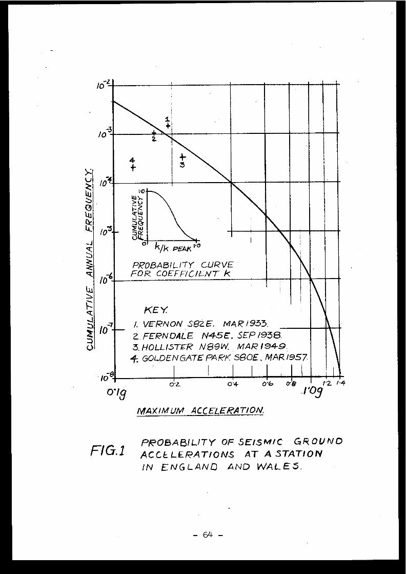
hhhhh.41.1iiii-~•o
9û
Z4J
okm PEAK "
P,POf3ABILITY CURVEFOR COEFF/C /E:NT k
KEY
►I. VERNON S 82 E. MAR/933.
Z FERNDALE N45E . SEP /938.
3. HOLLISTER N89W, MAR 1949 .GOLDEN GATE PARK 580E, MAR /957
0.
1 .2. I•4-1'03
lO L
/0 3
10
10
0./s0'4 0 6O•L
I /0
Io
/0
MA?(IMUMACCELERATION.
C7.1PROBABILITY OF SE/SM /C GROUN D
FI ACCELERATIONS AT A STATIO N
IN ENGLAND AND WALE5 .
64
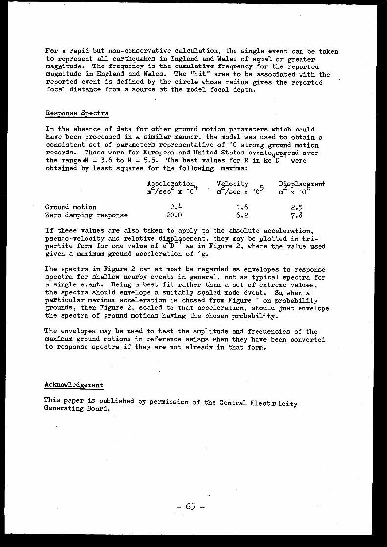
For a rapid but non-conservative calculation, the single event can be take nto represent all earthquakes in England and Wales of equal or greate rmagnitude . The frequency is the cumulative frequency for the reporte dmagnitude in England and Wales . The "hit" area to be associated with thereported event is defined by the circle whose radius gives the reporte dfocal distance from a source at the model focal depth .
Response Spectra
In the absence of data for other ground motion parameters which coul dhave been processed in a similar manner, the model was used to obtain aconsistent set of parameters representative of 10 strong ground motio nrecords . These were for European and United States eventsmtE ead ove rthe range è! = 3 .6 to M = 5 .5 . The best values for R in ke DD wer eobtained by least squares for the following maxima :
Ar2cele2ration4m /sec
x 10Vglocitym /sec x 105
DIsplacgmen tm x 1 0
Ground motion 2.4 1 .6 2. 5Zero damping response 20 .0 6 .2 7.8
If these values are also taken to apply to the absolute acceleration ,pseudo-velocity and relative dplcement, they may be plotted in tri -partite form for one value of e -D as in Figure 2, where the value use dgives a maximum ground acceleration of 1g .
The spectra in Figure 2 can at most be regarded as envelopes to respons espectra for shallow nearby events in general, not as typical spectra fo ra single event . Being a best fit rather than a set of extreme values ,the spectra should envelope a suitably scaled mode event . Sq when aparticular maximum acceleration is chosed from Figure 1 on probabilit ygrounds, then Figure 2, scaled to that acceleration, should just envelop ethe spectra of ground motions having the chosen probability .
The envelopes may be used to test the amplitude and frequencies of th emaximum ground motions in reference seisms when they have been converte dto response spectra if they are not already in that form .
Acknowledgement
This paper is published by permission of the Central ElectricityGenerating Board .
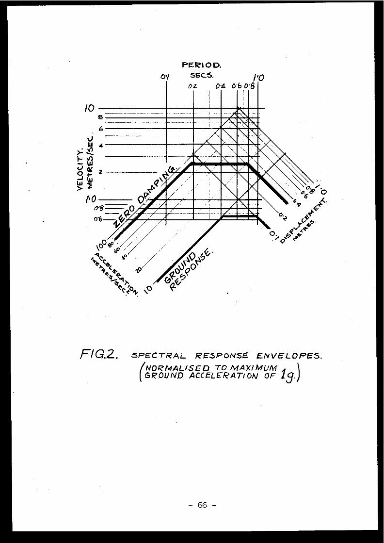
/0s
2
I- Oo'8
PERI O D.01
SECS.
/ .Ooz
oa 0 . 6 0'8
MirWW2E INVirjtk
AMA'AMNMNM
Adr,mvismirsuntm
NV '0
SPECTRAL RESPONSE ENVELOPES .1NORMALISED TO MAXIMUM
GROUND ACCELERATION OF 19
\O
0'6
FI G.2 .
[2 .3 ]
THE ASSESSMENT OF SEISMIC DESIGNCRITERIAFOR NUCLEAR POWER STATIONS
IN ENGLAND AND WALES
D . J. Mallard CEGB, GDCD, Barnwood, Gloucester, Englan d
J. Irving CEGB, GDCD, Barnwood, Gloucester, Englan d
P . A. Corkerton CEGB, NHSD, London, England
The paper describes the approach adopted by the Authors fo rthe specification of seismic criteria for the design of futur enuclear power stations . A description is given of the riskanalysis applied to the area in question and the choice o fconsistent ground motion records .
A short description of local ground conditions andinvestigations at the proposed SGHWR site at Sizewell i nSuffolk concludes the paper .
Cette communication décrit la méthode adoptée par les Auteur sen vue de spécifier des critéres seismi9ues pour la conceptio ndes centrales nucl4aires futures . On decrit l'analyse desrisgtsappliquée â la région en question et le choi xd'enregistrements cohérents des mouvements du sol .
La communication se termine par une courte description de sconditions locales , du sol et des investigations effectuée ssur le site propose pour une centrale SGHWR â Sizewell dan sle Suffolk.
Introduction :
Although England and Wales are conventionally considered to b eseismically relatively inactive, small earth tremors do occu rquite frequently and, on occasions, events exceeding magnitude5 have inflicted considerable damage . For instance, theearthquake of 1185 is known to have almost totally destroye dthe Norman cathedral at Lincoln, and the Colchester earthquakeof 1884 caused considerable damage over an area of about 150square miles . It is also true to say that an awareness of th epotential risk and the need for a proper appreciation of theproblem is long standing . Johnson's first physical atlas (185 0concluded that the whole of the British Isles was within the"Earthquake District" of Iceland :
Although the chances of any single reactor being affected byemearthquake of any significance are very remote, as the numbe rof nuclear power stations increase the chance of one of the sitesbeing affected increasest and so the CEGB intends that futurenuclear power stations in England and Wales will be designed t owithstand a number of identifiable external hazards. Thedesigner will now be required to consider seismic effect stogether with other natural and man-made phenomena such a sextreme flood levels and aircraft impact .
Zoning and Frequency :
The Global Seismology Unit of the Institute of GeologicalSciences (ICES) at Edinburgh have done a great deal of work i ncollecting the data on British earthquakes, using the recordsof research workers such as Davison 1924) for historica levents and their own instrumental readings for more recen ttremors . A distribution of seismic events in the UK wa sproduced by the IGS at the request of the CEGB, and this i sshown in fig . 1 . There is little evidence of other than rando mdistribution of events with the exception of •a recentsignificant peak of swarm events near Hereford and extendin ginto South Wales . Whilst this and other peaks in England an dWales may be regarded as centres of short-term hazard, the IGSdoes not consider that areas which have been quiet for the paBt200 years should be regarded as having less than the averag elong-term hazard . The authors considered therefore, thatzoning was not a practical proposition .
The IGS have also produced a graph showing the relationshi pbetween magnitude and frequency of occurence of events inEngland and Wales and this is shown in fig . 2. They arecontinuing to work, on this topic, particularly with regard t othe limit-off" limit of magnitude . It is understood that th eresults will be published within the next year and that thes ewill show some slight modifications although presen tindications are that the changes will not radically alter thecriteria under' discussion .
- 68 -
The IGS also indicated that the applicable levels of groun dmotions should be based on earth tremors of magnitude 5 .2 to5.5 and that instrumental observation indicated focal depthsin the range 7 .5 to 15 km.
Review of Strong Motion Records :
The problem is therefore somewhat unusual in that it involve spossible nearby small, shallow earthquakes which, in thepast, have received little attention. The work is furthe rcomplicated by the fact that there are no UK strong motio nrecords available .
Whilst strong motion instrument records exist in some quantityfor American and European events, it is difficult to relat ethese to UK cnditions . The present study has been base dprimarily on
data although some published detail sof European earthquakes,-for instance Ambraseys (1974) havebeen taken into account in deciding upon the propose dreference ground motions . Digitised records of US event sin the magnitude range of interest have been supplied b yImperial College and processed by the CEGB's Berkeley Nuclea rLaboratories (BNL) to produce acceleration, velocity ,displacement and energy time history curves, together wit hthe corresponding acceleration/frequency and velocity /frequency spectra.
Seismic Risk Analysis :
In the early stages of the investigation it was not though tpossible to extrapolate the earth tremor magnitude/frequencycurve (fig. 2) given by IGS significantly beyond magnitude 5with any real degree of confidence, and because of this i twas not thought advisable to attempt to predict the magnitudeof the earth tremor that should be specified for the safe shu tdown case . Therefore, design basis earth tremors wer eselected, based on the maximum tremor that would be expecte dto occur over the life of a power station from the frequenc yinformation supplied by IGS . It was envisaged that it woul dbe possible to establish a correlation between magnitude an dpeak ground velocities and accelerations from a detailedstudy of the available earthquake records and then by applyin ga simple factor of safety to these values, it would be possibleto arrive at safe shut-down ground motions .
However it soon became apparent that thè correlations betwee nmagnitude and maximum ground motions are, at best, valid fo ra relatively small geographical area (as discussed by numerou spapers such as Milne and Davenport (1969) and, at worst, vali dfor a single earthquake . Additionally, the validity of thes ecorrelations becomes more questionable as the focal distanc eof the eatthquake decreases . This latter point is discussed ,with particular reference to strong earthquakes, by Ambraseys(1973) . Fig . 3 demonstrates the difficulty by comparin gthe Esteva (1969 and 1974) correlations, based on west coastAmerican records, .with European data.
-69-
It should be borne in mind that the scatter in the events fromwhich Esteva derived the formulae covered a similar range tothat of the European data .
The literature on non-American data shows that, in epicentralregions of shallow earthquakes corresponding to the typ eexpected in this country, the peak ground accelerations ca nbe very large indeed, even for quite small earthquakes an dthat, if the simple approach referred to above for specifyingthe safe shut-down criteria were retained, it would lead to .large maximum ground accelerations approaching 1 .0 g o rpossibly even greater .
Further complications arise from the fact that the consensusof expert opinion (McKenzie (1975)) appears to indicate thatthe nature of vibrations received at similar epicentraldistance and focal depths in relatively inactive areas maywell be different from those received in a more active region .That is to say, there will be less attenuation of the highfrequency components in the inactive area .
The authors also came to the conclusion that, in the case o fEngland and Wales, there was no logical reason why therelationship used elsewhere between the design basis and safeshut-down earthquakes should apply. Logically the DBE i sseen in this case as purely an investment protection criterionwhich may vary from one component to another. It is inter-esting to note that since reaching these opinions simila rthoughts have been voiced by a number of engineersparticularly some of the American participants at the 3rdSMIRT Conference held in London in September this year.
It was therefore decided to attempt a probabilistic approac hto the specification of ground motions for the safe shut-downcase on the assupption that earthquakes occur in a rando mfashion throughout the country at the frequency predicted b ythe IGS . To calculate the probability of a given sit eexperiencing a specified level of acceleration or velocit yit is necessary to use one of the published "non-relevant "correlations with magnitude . This apparent anomaly has beendealt with by the expedient of assuming that the Esteva (1974)relationships allow the calculation of the probability o fexceeding a given peak acceleration or velocity and that thi svalue can be assigned approximately 50% confidence level .The maximum peak values that are possible at a given site willbe higher because of the scatter of results about thecorrelation curve as typified by fig . 3. The probabilitie scorrésponding to_other confidence levels can be found byallowing in the calculation for the scatter .
To produce the probability curves shown in figs . 4 and 5 themagnitude/frequency of occurence .line has been extrapolatedbeyond magnitude 5 using arbitrary cut-off points at 0 . 5magnitude increments . The Esteva equations have been use dwithout addition of a scatter band so that the probabilit ycurves have a 50% confidence level . The curves illustrat equite clearly how the velocities and accelerations increase
with increasing magnitudes of earth tremors and decreasin gprobability levels . However, it should be noted that th econfidence limits that can be put on the velocities an daccelerations at the lower probability level are ver yuncertain and the applicability of the available data ofearth tremors in this country would certainl z6not supportthe use of the curves at probabili ty es of 10 or beyondat magnitudes significantly above 5 . It is interesting t onote that a similar type of risk analysis has been carrie dout by Cornell and Merz (1975) for the Boston area wit hsimilar results .
It is judged that ground motions for the safe s4ut-down cas efor an SGHWR station should be based on the 10 probabilit ylevel which has the merit of being consistent wit hprobability levels adopted for other hazards such as win dspeeds, tides etc .
Ground Motions for Safe Shut-Down Case :
Once the approximate mean peak velocities and acceleration swere determined it was necessary to produce ground motio ntime-histories which would be specified to the designers .This was achieved by selecting the most appropriate America nearthquake records with regard to magnitude, epicentral dept hetc . and the twelve selected are given in table I . Thevelocity and acceleration spectra provided by BM for thes eearthquakes were then plotted and these plots are given infigs . 6 and 7. By inspection it can be seen that th eParkfield 5 station recordings from the 1966 Parkfield eventconveniently envelope the other spectra, and Parkfield 5 wa stherefore selected as the reference earth tremor . It was als odecided to recommend that the Temblor recording of the sam eearthquake should also be specified to the designers in orde rto ensure as far as possible that all the velocity an dacceleration frequencies within the spectrum are covered an dto allow for a variety of soil conditions at the instrumen tsite . It was intended to scale the chosen earth tremor sso that the peak velocity would eorrespon dkto the velocitygiven by the probability at a .level of 10-'. In the event ,both the maximum velocity and maximum acceleration of theParkfield 5 and the Temblor events were quite close to th erequired 'values and therefore scaling was unnecessary . Anadditional factor taken into account in choosing thes eparticular earthquake records was that they contain aconsiderable amount of high frequency content, which, a sstated above, is thought to be important in UK type conditions .The selected time-history records can be considered as fre efield horizontal firm ground motions at any site in Englan dand Wales for the purposes of establishing safe shut-dow ncriteria for all future nuclear power stations .
Vertical Motion :
The opinion is widely held, and most recently expressed b yHall, Mohraz and Newmark (1975), that a relationship of abou t
-71 -
two thirds between vertical and horizontal accelerations i sgenerally observed . The chosen records for the Parkfiel dearthquake do not show this relationship over the whol efrequency range . The decision has therefore been made thatthe chosen horizontal motion components should first b ecombined with the actual measured vertical motion and the nwith an aPtificial vertical vibration equal to two third sof the horizontal. This may well prove to be a conservativeapproach and the whole subject of in-phase or out-of-phas evertical motion is still under active consideration withi nCEGB . Consideration is also being given to the problem o fspecifying how the various components should be combined fo rthe purpose of the design analysis .
Effects of Local Ground Conditions :
The motions at fondation level will need to be establishe dfor each site depending on the soil conditions . If softground is present (defined as having a shear wave velocityof less than 500-600 m/sec) then a mathematical model ,layered if necessary, will be derived and a lumped massapproach used to analyse the modifications imposed by thesoil, see Dowler, Fullard and Simpson (1975) .
The first investigation into seismic parameters is currentl yproceeding at Sizewell in Suffolk where preliminary result sfrom cross-hole shooting and more conventional geophysica lmethods indicate that the granular material rapidly reache sthe firm ground conditions .
Had this not been the case, the preferred method o festablishing parameters for use in analysis would, in thi sinstance, have been to extrapolate the low strai ngeophysical moduli figures using published relationships .This decision applies to Sizewell and not necessarily toother sites, because the authors consider that direc t"undisturbed" laboratory high strain measurements would no thave been worthwhile on this particular granular material .
The Standard Penetration Test (SPT) results at Sizewellindicate little likelihood of liquefaction and compactio nsettlement studies are being undertaken by comparing in-sit udensities measured directly, and by SPT, and by gamma raymethods with laboratory measured maximum density values .
Conclusions :
It is the intention of the CEGB that future nuclear powerstations shall be designed so that the reactors can be safel yshut-down and cooled when subjected to the specified eart htremors without causing an unacceptable release o fradioactivity at the station boundary .
This paper has outlined the philosophy behind the derivatio nof suitable seismic design criteria on the best informatio navailable to the authors at the present time .
72
Although the criteria are still subject to modification beforebecoming firm CEGB requirements, the authors present view isthat, in general, it will be necessary for the designer t oshow that safety-related plant can withstand the specifie dsafe shut-down earth tremor and that non-linear behaviou ri .e . ductility and reserve energy, can be invoked_ todemonstrate that these requirements are met . The analyticaltreatment of the design aspects is discussed by Dowler ,Fullard,and Simpson (1975) .
Finally it is necessary to say that the authors are aware o fthe need for continued study of the many problems associate dwith specifying seismic design criteria and fully anticipat ehaving to revise the specified ground motions as mor einformation becomes available .
Acknowledgements :
The authors are grateful to the Central ElectricityGenerating Board for permission to publish this paper an dwith to asknowledge the assistance of a number of engineer sand seismologists whose advice has been of assistance i nformulating these design criteria . The advice ofDr . Willmore of IGS and Professor Ambraseys of ImperialCollege has been particularly valuable .
References :
AMBRASETS, N .N . (1973)Dynamics and Response of Foundatio nMaterials in Epicentral, Regiones o fStrong Earthquakes . Invited Paper, 5thWorld Conference on Earthquake sEngineering, Rome .
AMBRASEYS, N .N . (1974)The Correlation of Intensity with Groun dMotion . 14th Conference EuropeanSeismological Commission, Trieste .
CORNELL, C .A . AND
Seismic Risk Analysis of Boston . Proc .MERZ, H .A . (1975)
Am . Soc . Civ. Eng ., Journ . Struct . Div . ,Vol . 101, ST10, pp . 202?-2043 .
DAVISON, C. (1924)
A History of British Earthquakes .Cambridge .
DOWLER, H .J., FULLARD,Design and Research Aspects of theK. AND SIMPSON, I .C . Treatment of Earth Tremor Effects on(1975)
Nuclear Power Plant Structures an dComponents. CSNI Specialist Meeting o nAnti-Seismic Design of Nuclea rInstallations, Paris .
ESTEVA, L . (1969)
Seismic Risk and Seismic Design Decisions.Seminar on Seismic Design of NuclearPower Plants, Cambridge, Mass . MIT Press .
ESTEVA, L . (1974) Gecdlogy and Probability in the Assessmen tof Seismic Risk . Proc . 2nd InternationalCongr . .Assoc . Eng . Geology, Sao Paolo .
-73-

HALL, W .J ., MOHRAZ, B . Statistical Analysis of Earthquak eAND NEWMARK, N .M .
Response Spectra. 3rd Conf . SMIRT(1975)
London . Volume 4, Part K paper 1/6 .
JOHNSON, A.K . (1850) The Physical Atlas of Natural PhenomenaWilliam Blackwood and Sons, London an dEdinburgh .
MCKENZIE, D .P . (1975) Private Communication .
MILNE, W .G. AND
Earthquake Probability,Proceedings 4thDAVENPORT, A .G . (1969) World Conference on Earthquake s
Engineering Vol . 1 . pp . 55-68 .
74
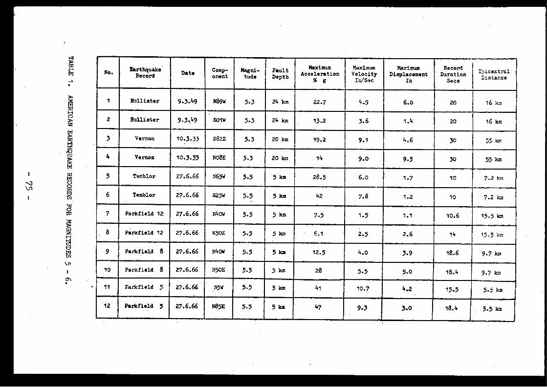
No . EarthquakeRecord Date Comp-
onentMagni-tude
FaultDepth
MaximumAcceleration
% 6
MaximumVelocityIn/Sec
MaximumDisplacement
In
RecordDuration
Secs
E-icertûlDistanceDistance
1 Hollister 9.3.49 N89W 5.3 24 km 22.7 4 .9 6.0 20 16 km
2 Hollister 9.3.49 solve 5.3 24 km 13.2 3 .6 1 .4 20 16 km
3 Vernon 10.3.33 S82E 5.3 20 km 19 .2 9.1 4 .6 30 55 km
4 Vernon 10.3.33 N08E 5.3 20 km 14 9.0 9 .5 30 55 km
5 Temblor 27 .6.66 N65W 5.5 5 km 28.5 6.0 1.7 10 7.2 kn.
6 Temblor 27 .6.66 S25W 5.5 5 km 42 7.8 1 .2 10 7.2 km
7 Parkfield 12 27.6.66 N40w 5.5 5 km 7 .5 1 .5 1 .1 10.6 15.5 km
8 Parkfield 12 27.6.66 N50E 5 .5 5 km 6 .1 2 .5 2.6 14 15.5 km
9 Parkfield 8 27.6.66 N40W 5.5 5 km 12.5 4.0 3.9 18.6 9 .7 km
10 Parkfield
8 27.6.66 N50E 5.5 5 km 28 5.5 5.0 18.4 9.7 k m
11 Parkfield
5 27 .6.66 N5W 5.5 5 km 41 10.7 4.2 15.5 5.3 km
12 Parkfield
5 27 .6.66 N85E 5.5 5 km 47 9.3 3.0 18.4 5.5 km

CENTRAL ELECTRICITY GENERATING BOARD
HEADQUARTER S
• •
FIG 1 . MAGNITUDES AND EPICENTRE SOF EVENTS SINCE I800
From a draft of projected IGS publication
96/16644
-76 -
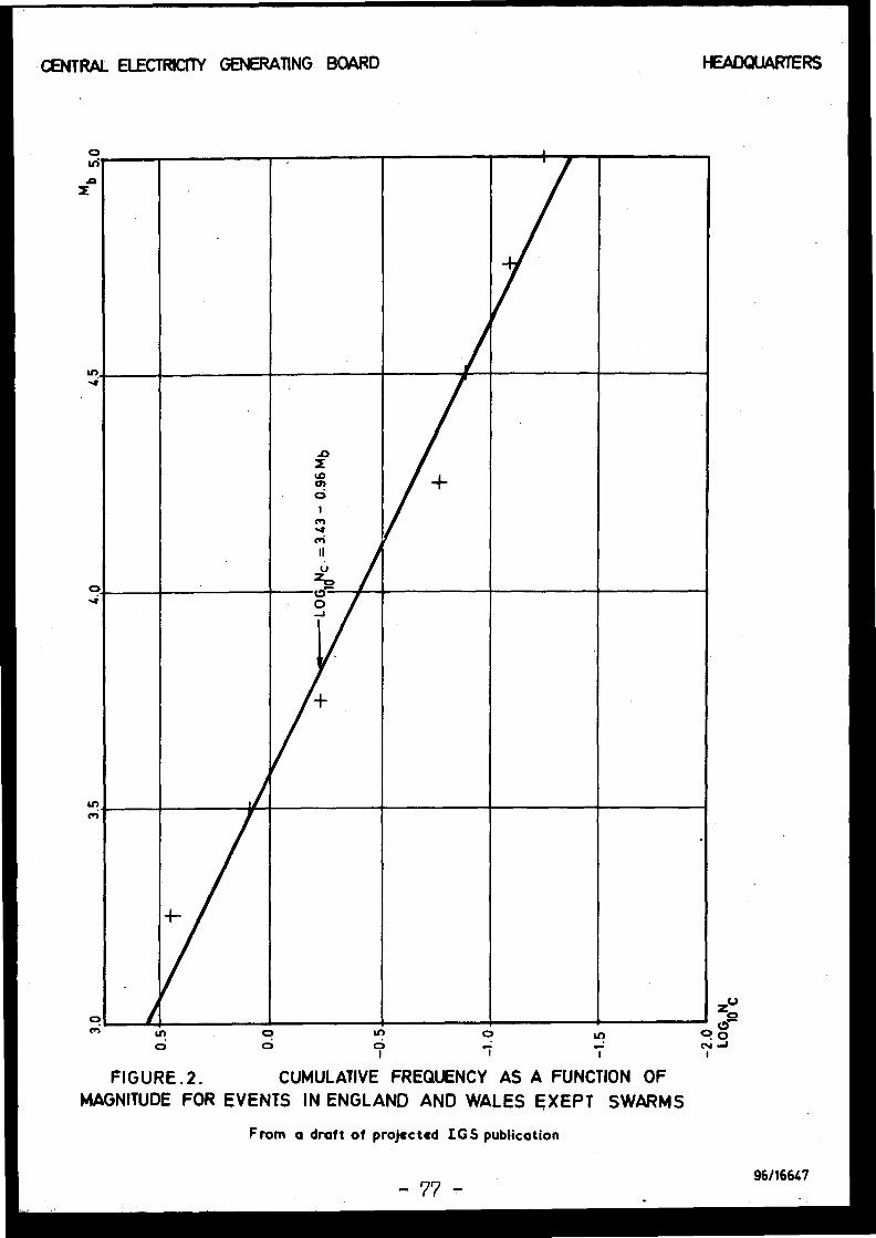
HEADQUARTERSCENTRAL ELECTRICITY GENERATING BOAR D
OMi
Orf
1
tDô
1
+
crivcri
IIu
OJ
NO
O
PIGURE .2 .
CUMULATIVE FREQUENCY AS A FUNCTION O FMAGNITUDE FOR EVENTS IN ENGLAND AND WALES EXEPT SWARM S
From a draft of projected IGS publicatio n
-77 -96/1664 7
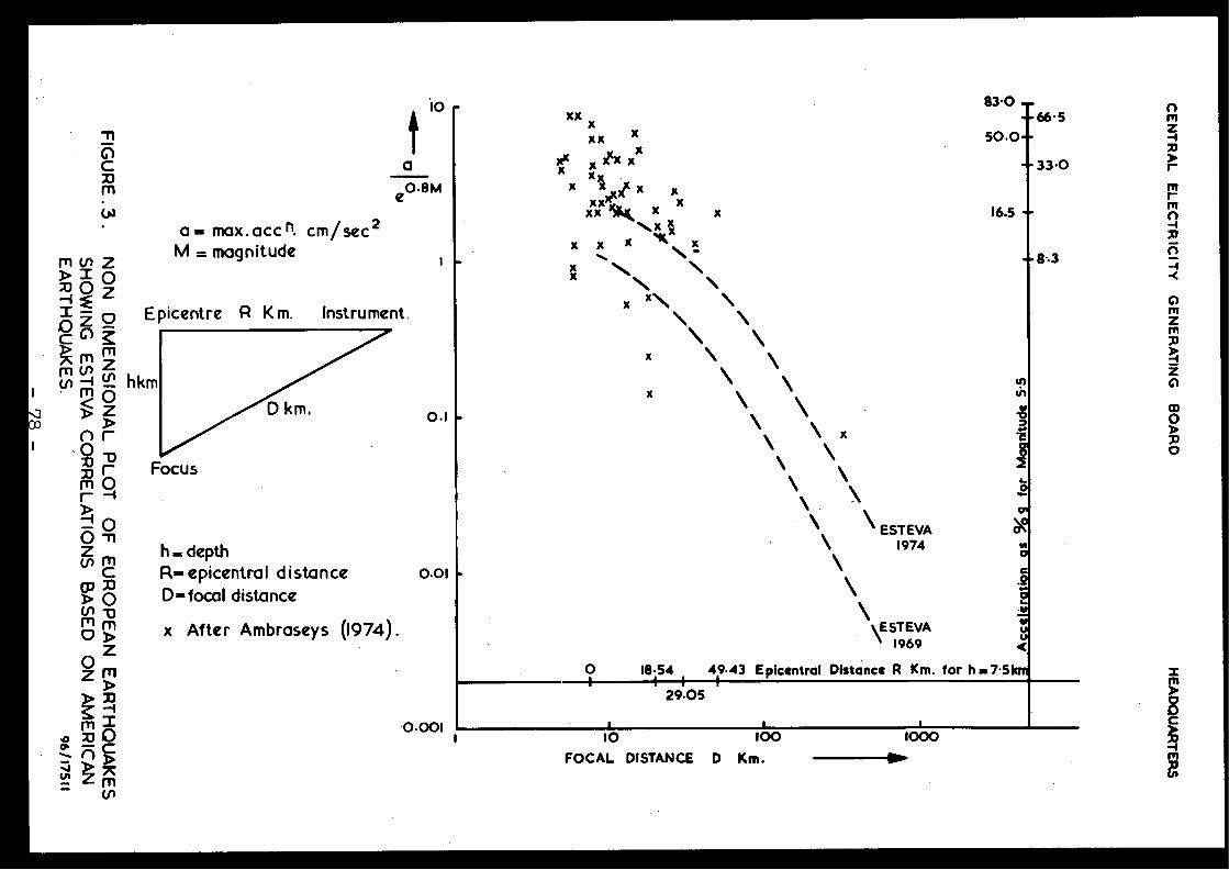
0-c
arn
e0-8M
co'
10
xxxx xxx
-33 .0
83.0xx x
-66. 5xx x
50 .0 ~
x xXcx
xx
xx ISK xx
x
16 .5 -\x X
x x x
x
x-8•3
x
x x
a== max . acc n. cm /sec 2
rn v) Z
M = magnitude
> 1 0
.0Z Oc m Z
rn
cmnm
hkm< oD DrÔXI rm Or
O
z m
h=depth
c
R-epicentral distance
o.ol
D O
0-focal distancecn -om mo >
Z
Z DE
rnO
0 .00 1n
rn
Epicentre R Km .
Instrument .
0. 1
Focu s
x After Ambraseys (1974) .
\\`ESTEVA
196 918 .54
49-43 Epicentral Distance R Km . for h=7.5km
29.05
\ EST EVA\
1974\
av
I
10
100
FOCAL DISTANCE D Km .
1000
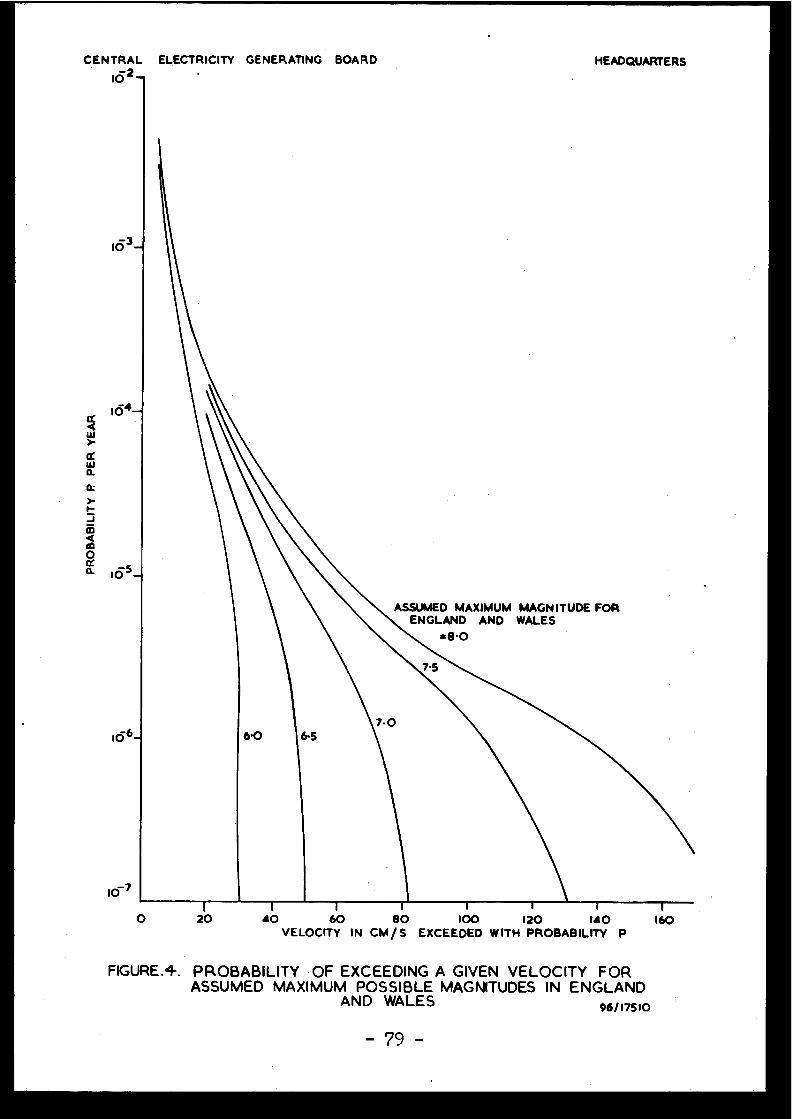
CENTRAL ELECTRICITY GENERATING BOARD
HEADQUARTERS1Ô2 -
FIGURE .4. PROBABILITY OF EXCEEDING A GIVEN VELOCITY FO RASSUMED MAXIMUM POSSIBLE MAGNITUDES IN ENGLAN D
AND WALES
96/17510
ASSUMED MAXIMUM MAGNITUDE FORENGLAND AND WALE S
=8.O
OI
1
I
i
1
I
I
120
40
60
80
100
120
140
160VELOCITY IN CM/S EXCEEDED WITH PROBABILITY P
- 79 -
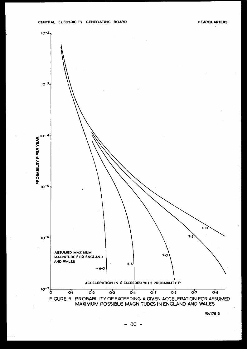
CENTRAL ELECTRICITY GENERATING BOARD
HEADQUARTERS
10-2
10-3-
t0-7O
ASSUMED MAXIMU MMAGNITUDE FOR ENGLAN D
AND WALES
ACCELERATION IN G EXCEEDED WITH PROBABILITY P
O1
0 . 2
O3
0.4
O5
0.6 O7
O 8
FIGURE 5. PROBABILITY OF EXCEEDING A GIVEN ACCELERATION FOR ASSUME DMAXIMUM POSSIBLE MAGNITUDES IN ENGLAND AND WALE S
96/17512
- 80 -
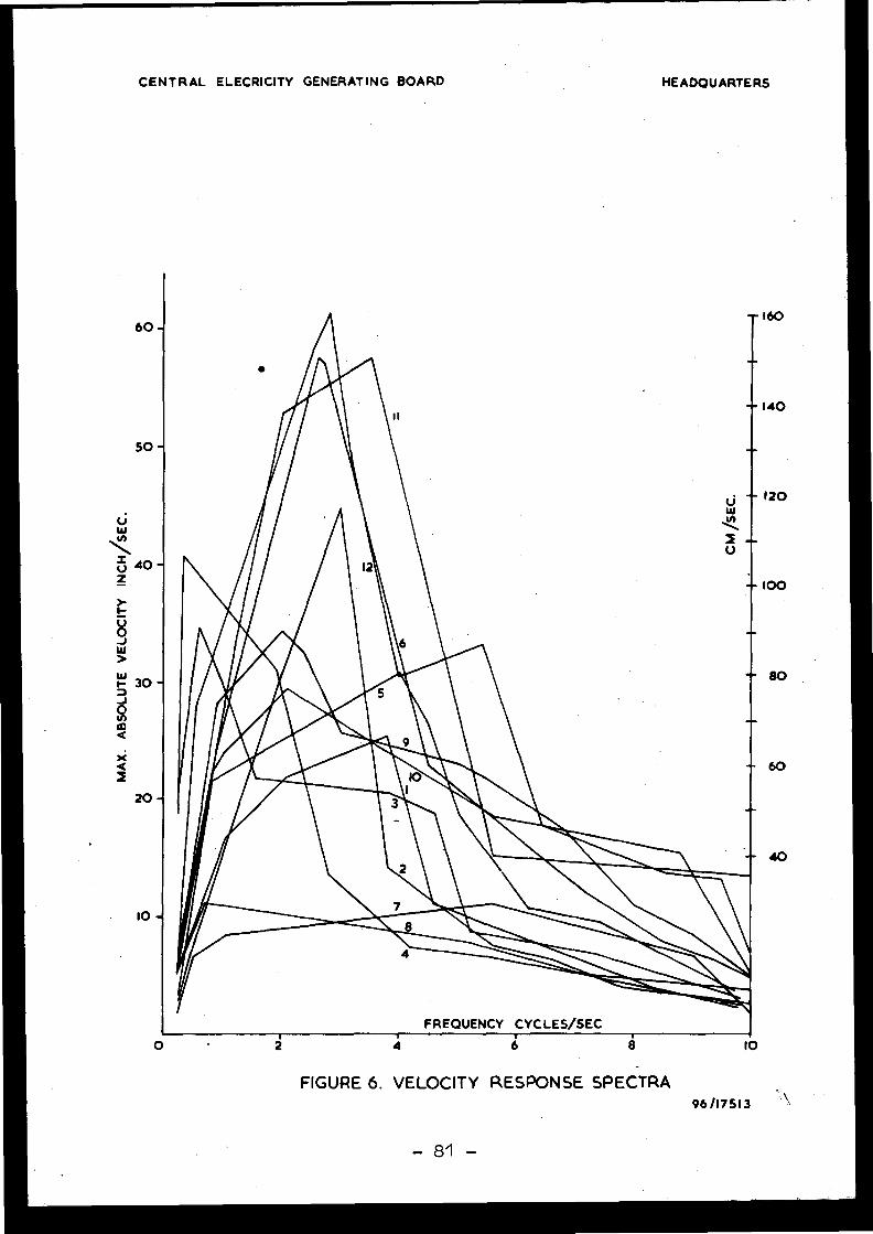
CENTRAL ELECRICITY GENERATING BOARD
HEADQUARTERS
60 -
50 -
xa2
-
FREQUENCY CYCLES/SEC
4 8 10
FIGURE 6. VELOCITY RESPONSE SPECTRA96/1751 3
- 81 -
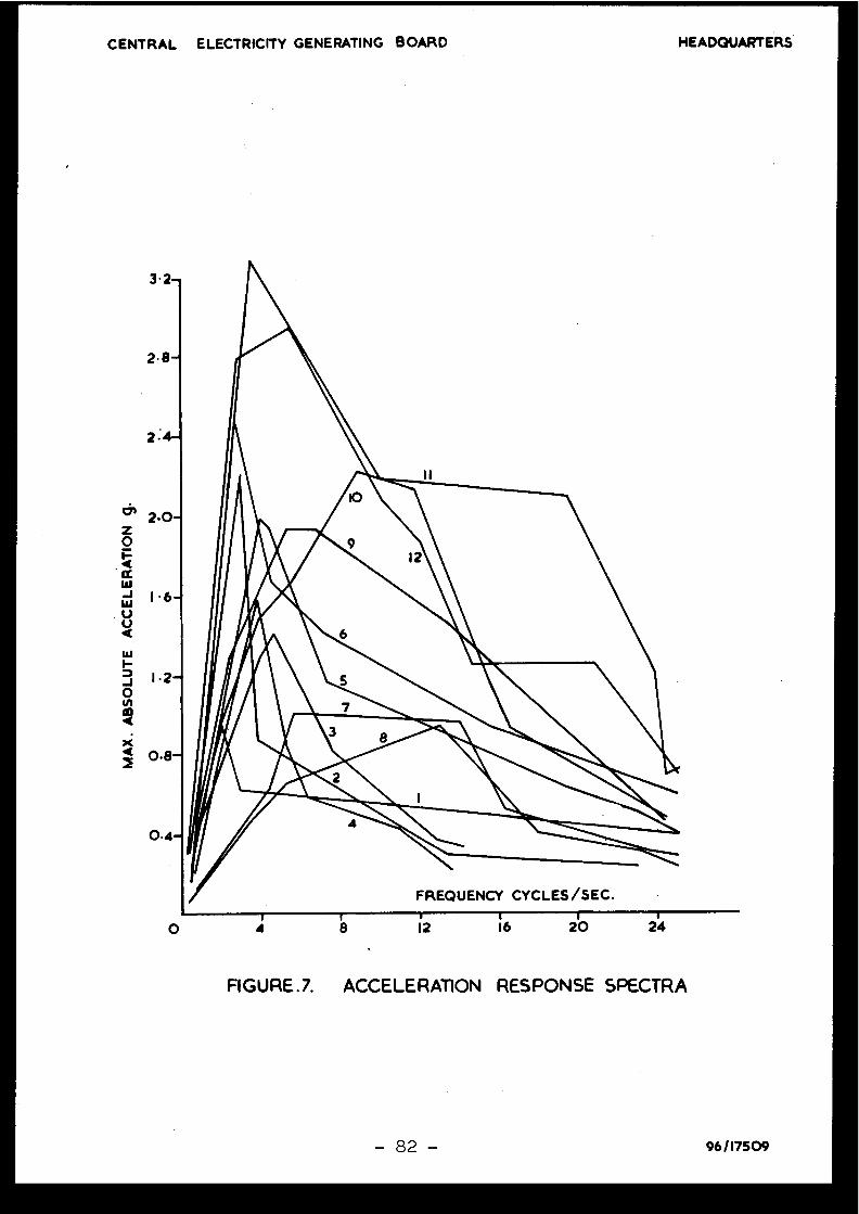
CENTRAL ELECTRICITY GENERATING BOARD
HEADQUARTERS
FIGURE .7. ACCELERATION RESPONSE SPECTRA
O
- 82 -
96/17509

Discussions
J .P . ROTHE, France
En tant que sismotectonicien, je m'étonne qu'on nepuisse pas faire de distinction entre les différentes région ssismiques d'Angleterre et d'Ecosse .
J.IRVING, United Kingdom
The study described in our paper was concerned wit hEngland and Wales alone ; Scotland was excluded . The area ofWales shown in Figure 1 as having no recorded events is proba -bly not typical since this area is sparsely populated in com -parison to the remaining area and would therefore be unlikelyto have the same density of observed historical records eventhough the actual frequency of occurrence is probably the sameas in the more heavily populated areas where there is apparent-ly a higher frequency of occurrence . Over a long time-scal ethere is no reason to believe that there will be any differencein general seismicity between one area and another .
J .P . ROTHE, Franc e
A l'examen de la figure qui a été projetée, je cons-tate qu'on a prévu des magnitudes allant jusqu'à 8 . J'espère ,pour l'Angleterre, que de tels séismes ne se produiront pas .Avez-vous considéré une magnitude maximale pour l'Angleterre ?
J.IRVING, United Kingdom
The curves shown in Figures 4 and 5 are intendedmerely to illustrate the effect of "cut-off" on probabilitie sof exceedance of a given velocity or acceleration . In practice ,the probable "cut-off " magnitude is between M = 5 and 6 . Inany event at the 10-4 probability level these figures showthat there is little practical difference between cut-offmagnitudes ranging from 6 to as high as 8 .
P.GIULIANI, Italy
Do you propose to have an evaluation of. the lique-faction potential at the Sizewell site by methods other thanthe SPT mentioned in the text ?

J. IRVING, United Kingdom
The study of liquefaction potential at the site i sstill at a very preliminary stage ; other methods may well b eused but I am unable to give you any further details othe rthan to say that this subject is being actively pursued .
Addendum to the paper
The Assessment of Seismic Design Criteria for Nuclea rPower Stations in England and Wales
We outline in our paper the method we have used todetermine reference ground motion data for the safe shutdownearth tremor . The largest uncertainties involved in the pro-bability approach lie in the use of scaling laws for accelera -tion and velocity . Mr . Oliver has suggested, in his paper, on emethod of dealing with this difficulty using a peak groundacceleration/frequency distribution . Our own approach was t oassign approximately 50 % confidence limits to the Esteva cor -relation curves in the derivation of the overall probabilitydensity function for the exceedance levels of peak accelerationor velocity in England and Wales . As the plot in Figure 3 o four paper shows, recorded earthquakes exhibit considerabl escatter about the mean correlation curves . We believe it i simportant that the reference ground motion for the safet yloading case should take account of the well-known correlatio nof observed events with the Esteva curves and for this reaso nwe have investigated the effect of scatter on the derived pro-bability of exceeding a given peak acceleration of velocity .These are shown in Figures 1 and 2 (attached) for velocit yand acceleration respectively . These curves were derived i nthe same way as those in our paper except that one standar ddeviation from the mean of acceleration or velocity has beenadded . The value of the standard deviation was found from th erecorded data shown in Figure 3 of our paper . Figures 1 and 2(attached) show the effect of this adjustment ; the curves t othe right of the mean line represent the 1/6 upper confidenc elimits on the curves . It can be seen-that the difference bet-ween the upper confidence limits and the mean line increase sgreatly with increasing "cut-off" magnitude and decreasingprobability . This is clearly shown for the notional maximummagnitude 8 curves . However, where there is reason to believ ethat the "cut-off magnitude lies between 5 .5 and 6.0 a smalleradjustment is required to establish the choice of referenc eground motion data at a given probability level - indeed th easymptotic nature of the 5 .5 and 6.0 level curves shows tha tthere is little difference between the reference peak accele-ration or velocity for probabilities in the range 10-7 to 10-4 .
We conclude,that, in areas of low seismicity such a sour own, the probability approach to the choice of referenc eseism for the safety case is the most logical and supportable ,and is preferable to zoning. We would however, agree tha tzoning is possible where this can be firmly related to knowntectonic features .
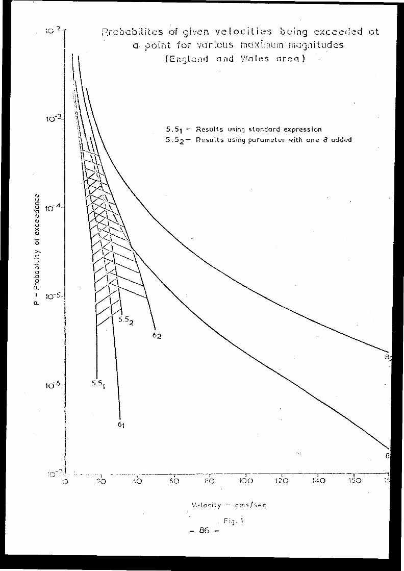
rcbobiti'(cs of gi .v,-m vetocitii.:s b ::'ing exceei .d a t
a. point for various
mcsl .-iitudcs
(EIcA and Wales area )
1o-3-
5 .51 - Results using standard expression
5 .52 - Results using parameter with one a added
n----r---T-- r0
~C3
:0
60
100
120
140
150
v,tocity - crns/se c
F i g . 1
- 86 -
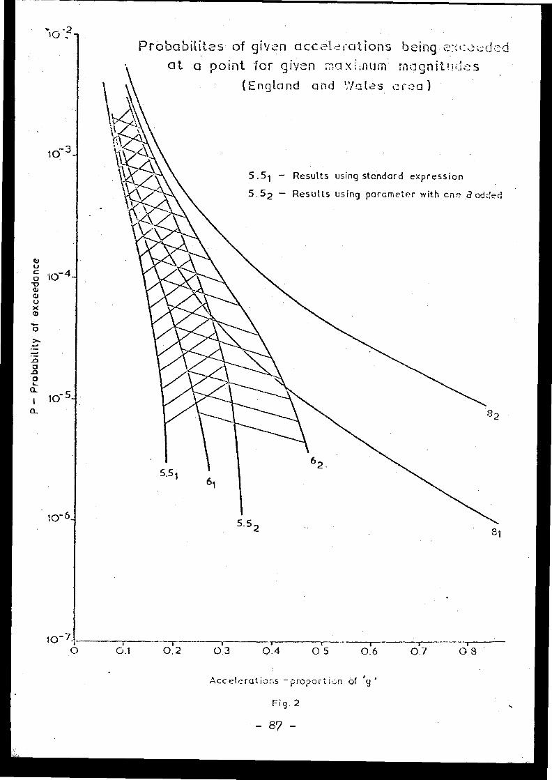
1o 3 -
1o-5 -
Probabiii os of given acceLl:1-ations being e :<co .-dcd
10-7-,0
G.1
0 .2
0.3
0.4
0 .5
0.6
0 .7
0 . 8
accelerations - proporti ..;n of g '
Fig . 2
- 87 -
. -at ci point for given maxi :num roognitt.id .F2 s
(England and Wales cr :aa )
5 .5 1 - Results using standard expressio n
5 .52
Results using parcmeter with cne dodc:!ed
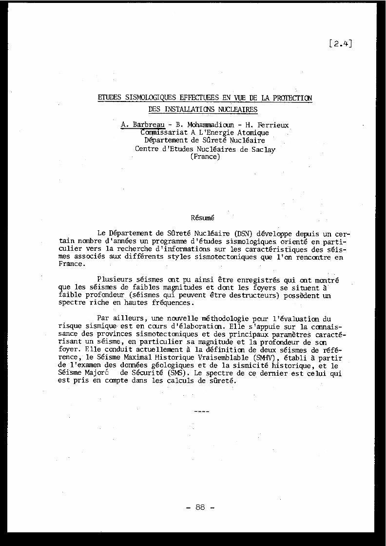
[2 .4]
ETUDESSISMOLOGIQUES EFFECTUEES EN VUE DE LA PROTECTION
DES INSTALLATIONS NUCLEAIRES
A . Barbreau - B . Mohammadioun - H . FerrieuxCommissariat A L'Energie Atomiqu eDépartement de Sûreté Nucléair e
Centre d'Etudes Nucléaires de Sacla y(France)
Résumé
Le Département de Sûreté Nucléaire (DSN) développe depuis un cer-tain nombre d'années un programme d'études sismologiques orienté en parti -culier vers la recherche d'informations sur les caractéristiques des séis -mes associés aux différents styles sismotectoniques que l'on rencontre e nFrance .
Plusieurs séismes ont pu ainsi être enregistrés qui ont montr éque les séismes de faibles magnitudes et dont les foyers se situent àfaible profondeur (séismes qui peuvent être destructeurs) possèdent u nspectre riche en hautes fréquences .
Par ailleurs, une nouvelle méthodologie pour l'évaluation d urisque sismique est en cours d'élaboration . Elle s'appuie sur la connais -sance des provinces sismotectoniques et des principaux paramètres caracté -risant un séisme, en particulier sa magnitude et la profondeur de so nfoyer . Elle conduit actuellement à la définition de deux séismes de réfé -rence, le Séisme Maximal Historique Vraisemblable (SMTV), établi à parti rde l'examen des données géologiques et de la sismicité historique, et l eSéisme Majoré de Sécurité (SMS) . Le spectre de ce dernier est celui quiest pris en compte dans les calculs de sûreté .
1 .
INTRODUCTION
La protection des installations nucléaires contre les effets de sséismes est un problème important qui doit être abordé dès le stade initialdu projet, puisque la prise en compte de ce risque influe directement surla conception même de l'ouvrage . Pour définir ce risque du point de vue dela sûreté, on choisit un séisme de référence caractéristique du site, di tSéisme Majoré de Sécurité (SMS), qui paür les besoins de l'ingénieur es tgénéralement exprimé sous forme d'une fonction temporelle (par exemple unaccélérogramme) ou d'un spectre de réponse de résonateurs . Ce signal d'en-trée sert ensuite aux calculs de génie parasismique .
Pour définir les caractéristiques du séisme susceptible d'avoirles effets les plus importants sur le site (SMS), il est nécessair ed'avoir une connaissance aussi complète que possible de la sismicité de larégion, de la magnitude des séismes, de leur localisation, de la profondeu rde leur foyer, des lois d'atténuation dé l'énergie en fonction de la dis -tance, du rôle des particularités géologiques locales dans la transmissio ndes ondes sismiques .
En effet, à défaut de l'enregistrement direct sur le site duséisme de référence, il faudra définir celui-ci sur la base d'hypothèsesdont le bien fondé dépendra de la qualité et du nombre d'informations uti -lisées pour les établir . Ces informations sont déduites essentiellement :
- des données historiques /1/, %2/, /3/, /4/ ,-d'une analyse sismotectonique de la région ,
- des enregistrements de séismes correspondant à des conditionsanalogues à celles du site considéré.
Une évaluation de la magnitude maximale, de la distance focal eminimale par rapport au site à prendre en compte pour le SMS, et des loisd'atténuation d'ondes sismiques en fonction de la distance, permet de défi -nir ce séisme .
2 .
ETUDESEFFECTUEES AU DEPARTENENT DE SURETE NLULEAIRE POUR L A
DETERMINATION DU SEISME DEREFERENCE
2 .1 Recherche des caractéristiques des séismes en France /s/
Depuis déjà de nanbreuses années, le Commissariat à 1'Energi eAtomique s'est soucié de rassembler des informations sur la nature du ris-que sismique en vue de développer une méthodologie .
En 1962, un observatoire sismologique a été installé au Centred'Etudes Nucléaires de Cadarache, et un réseau de stations sismiques éta-bli aux alentours, afin d'étudier la sismicité de la Provence . On a ensui -te mis au point et développé un réseau de stations sismologiques mobile sà enregistrement magnétique en modulation de fréquence et, depuis peu, e nnumérique pair étudier les séismes et les répliques de séismes (localisa-tion précise du foyer et détermination de la répartition spectrale del'énergie), ainsi que pair apporter des informations sur l'activité de sfailles et sur les caractéristiques locales de la transmission des onde ssismiques .
Récemment, le Département de Sûreté Nucléaire a proposé la réali -sation de la carte sismotectonique de la France, établie au 1/1 000 000 àpartir de minutes au 1/250 000, qui doit permettre de faire le point d etoutes les connaissances acquises dans ce domaine . Ce document, qui ne pré -tend pas à un rôle règlementaire, est conçu pair servir de base à l'ana-lyse sismotectonique des sites des installations nucléaires et pourra êtr eutilisé naturellement dans d'autres études de génie parasismique .
2 .2 Résultats obtenus
Grâce aux stations sismologiques mobiles, il a été possibl ed'enregistrer plusieurs séismes qui ont fait l'objet d'études détaillées .C'est ainsi que des enregistrements de plusieurs répliques du séisme quis'est produit dans la région d'Oléron le 7 septembre 1972 ont été obtenus .Un petit séisme dans la région du Tricastin a également été enregistré prè sdu Centre de Pierrelatte sur des alluvions . Les caractéristiques de ce sséismes sont données par les Tableaux I et II .
Les spectres de réponse représentés sur la Figure 1 correspon -dent aux enregistrements (ccanposante E-0) de quatre des répliques mention -nées (courbes 1 à 4) et à l'enregistrement (composante N-S) du séisme dansla région du Tricastin.
On voit que ces spectres de séismes ayant des magnitudes diffé -rentes, mais relativement faibles, sont riches en hautes fréquences . Lesdifférences entre les spectres des répliques du séisme d'Oléron et celu idu séisme dans la région du Tricastin, enregistrés à des distances épicen-trales comparables, peuvent s'expliquer par la présence des alluvions d uTricastin et par la différence entre les magnitudes de ces phénanènes : lespectre devient plus riche en basses fréquences quand la magnitude aug -mente .
Ces résultats ont été comparés avec des enregistrements de séis -mes de type analogue obtenus ailleurs dans le monde . On peut en conclureque les séismes de faibles magnitudes et de faibles profondeurs focale ssont généralement caractérisés, au voisinage de l'épicentre, par un spectr eriche en hautes fréquences, par de fortes accélérations et par une duré eassez brève . Les intensités macrosismiques qui leur sont associées peuven têtre équivalentes à celles produites par des séismes de plus grandes ma-gnitudes, mais à foyers plus lointains, qui ont une durée plus langue e tdont le spectre, décalé vers les basses fréquences, comporte des pointe sd'accélération moins élevées .
On conçoit donc que les caractéristiques du Séisme Majoré d eSécurité doivent être adaptées à la nature réelle des séismes locaux e tqu'il est souvent hasardeux de généraliser des résultats propres à un erégion .
3 .
RECOMMENDATIONS ACTUELLES DU DEPARTEMENT DE SURETE NUCLEAIRE E N
MATIERE D'EVALUATION DU RISQUE SISMIQUE
Une règlementation nationale est en cours d'élaboration . En at-tendant que cette règlementation soit établie, le DSN a proposé une métho -dologie temporaire .
La méthode préconisée actuellement s'appuie essentiellement sur
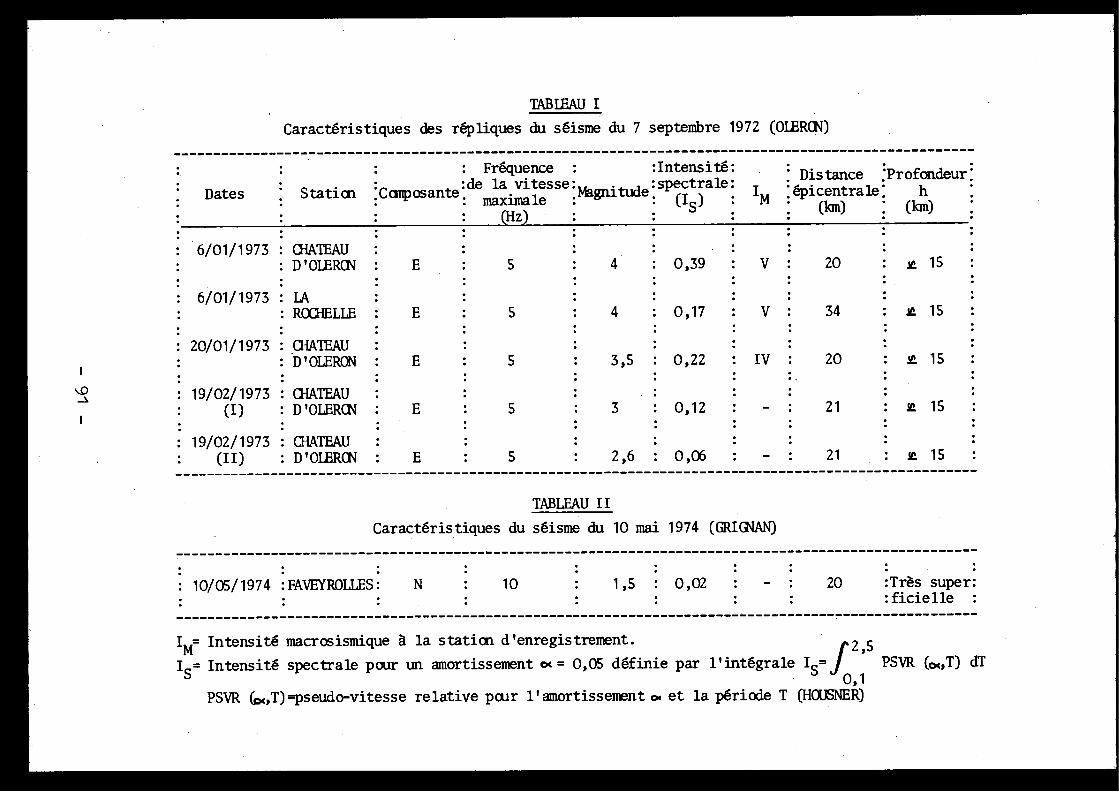
TABLEAUI
Caractéristiques des répliques du séisme du 7 septembre 1972 (OLERCN)
- ----------------------------------------------------------------------------------------------------
: Fréquence :
:Intensité :
:▪ Distance ;Profondeur ;
•
• Dates ••
Statice ;Composante:de la
fesse : gni e :sp(1s)tale .
IM ;épicentrale ; h(fan) ; (km)(Hz)
6/01/1973 CHATEAU. D' OLERCN E
5
4
: 0,39
V
20
: ▪ 15
6/01/1973 : LAROCHELLE :
E
5
4
: 0,17
V
34
: i 1 5
20/01/1973 . CHATEAU: D'OLERON :
E
5
19/02/1973 : CHATEAU
(I)
: D'OLERCN .
E
5
3
. 0,12
-
21
1 5
19/02/1973 . CHATEAU
:
(II)
D'OIERCN
E
5
2,6 : 0,06
-
21
1 5----------------------------------------------------------------------------------------------- ------
TABLEAU I I
Caractéristiques du séisme du 10 mai 1974 (GRIG1AN )
- ----------------------------------------------------------------------------------------------------
. 10/05/1974 :FAVEYROLLES :
N
10
1,5
0,02
-
20
:Très super ::ficielle
IM Intensité macrosismique A la statice d'enregistrement .
2,5IS= Intensité spectrale pour un amortissement « = 0,05 définie par l'intégrale ISJ
PSVR («,T) dT0, 1
PSVR (pc,T) =pseudo-vitesse relative pour l'amortissement« et la période T (HCUSNER)
3,5 : 0,22
: IV :
20
:
15
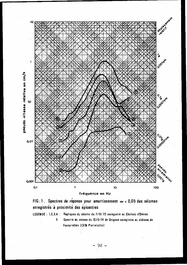
Wlla 4t&AV :88PWraMWII« ri!Y.%IIM:4 :4rn illP& r I»AMIAhlI I7►O:CAPAr4rAP& IINIP i ► .. :.uLVo0o~0~VAl~ia rdlnIIE.1l11:11Oe MilMil Ni 01lJ111n1P ►•n•LMe.n C.Yr.QIilMA M•~ ::r.►~oo4!Mi i00IMMIM1Y .111et.►7iov:`VMillntAY.i1 lenIPi"Y o`M ,OIRAIV..~11e h► !o~Xt':i; h rA/./Oli!dOi9 q►%!i:OZr=AIP.irMIN11 011tiOJ►KAI!•it"~1sri011iA11i1gC
w21.0i1 MI1111111=a111ICI'Cir I01.4i` 4111 IlO.►/ta NM►. NMIC "ftIN, 21, ,10P:a0.1 III E8*
I/p~~~B°I Ir%` t.d: e~t~~~r ®1i~Cbé â~rg®~ q~~r ta1aAt50 1111
►
rp rim `ray
~r ►
` ►"~ y1
2' r ►1hN ~ ►•~
Fp
Nrtia'iltoia.4kahoi&PIgIlig t.fiNittqE Atit
dg"LIrel toNlip-10
0 4*Md 'MEA41t
MOOLM nI\.‘Ihlle•ov r.4KaO;►wrroC111ayv.Mri/.amwr:vhrAClaM743 o3Ir•OdJnlrW r.AVM.0110.11.VSCS0W .ift•JI1r.►~~I.C"I.0/illf .1ri?MoI )INIWIP211nEUa►who:?P~►MIMAI1 PMMOU1 111EVI4002t`é%'OP;iar
iU.1NV.i~o
MtAMIE‘11110.11's+J►w6.0~a►r+dC~IIOP:iIgQ'+ rdN1.H►!O~!'O: : ~~!~ .~l/./
/C1~OÎr!~.OZq►!►~L!~I~ ' re a.
Yf+. ~f ~ M
• `Ir d' ,fir•
,rr r ~ ,~•
~•,r ~►~
err ►
,• y►a'
,ire,
ir PALIV4 ' *N1r; tt
ggI " :r 1I~vi '•. '~
'~r ► ~r~`+i~ V: ::'Wt U %,n~.d, .~~~~~%A
g~J1. Iv.o a ►é
MId~► ,dVi1► .+Il,eig ta4r iged .11:
w
v,, 4
10i~•'rr~N1P• r~~p•
•` p1P'ir ~IpA'~O ~
r .
,ra yV~r
baOT0.1►1~ d1
► ~~i ►1~
', i ►.A49 ►0~,, r r~
4iWL1 1 !g It ►~,►.~
a ~~ .~ t d,14 ►
r.
ü 1►'@
iki. am,: ►!d&o ►I*i`LV.esJrm.:orbtrAISPAIIIIMpYairrl► 92M )'a'o rrap ! : OMP'd. i .+-.:. r.mmeieremp Yk ac11tLf►!i ►'7►:.o_iYSArrC à`Op'JIA.VI
a• 'AMI410=n.E: L'n iraë.W,.dPAIrOMMI .*Vwp:!gIZ40''lei! CIf ittaraillfilgir A Sot=.i'4iIIP,CAMRIIR.i1O►A '~o .a~gP:tl110Na~I1P.yY1~pMW w dilld;'/iib =Il O,!i;M' MAIlEiglllnIOi9111M.'o:~ :v+l~ ~illlC~llldigIarn:;St:0~'0";1►►:C11I lid INI!, K Ç~.ly CM tt511d~,''
►!:~!®~1►0~ ►:;ta
°~Ir ;ba`,~
r ~Fr i .,i~V/ i .'r
.~. m•o cq .~, ,8 ~p•
•1r
►
v ~I ~~cit.b 'r ,1r ►SIM /i•~p9i1
94'r ► IN ' ~"~
is
'.~1~ ►km. 4AAAh .
UPJ ►.~~!~, • ., .d~'' ►
ate . Ni .it:►t+d, l le.0 , NP 1 .lli $►_
"NMOG~IJIfl .9
►6 d~? ► ivi
,t roveor `►~ apepal;.i
~
~AtIb
,r,►~;►~~ ►~~>_►mort:d~~~~_~. : _.~la kW '4'b
MPANDNVA
.l tes 040é
LM
P ikli 1R46411V945I
4F 1n 1$as..t~►~:~irwmr '
410,6coull'ht3!'A. ,,
AL. .1, )4%. .Aeo':rst'' '
!tgn''SknlrrrW4'm,rJmr.n~.rac u
s►F'0.A.1Z rar 201PUI11ur 7A S'S_. Ne' v,ArrlltrIKMIOM.►ra ►ta .3C'TidlZOrilra MOlCaY•►i:gttn :1.O10MM'iVO►7rJ rq@►i~o~ dril l pMMOMY.10~p►►.r~i;do MOr:QCI M1 C ONV Ontl'4:►.g;NitiaiMI
M`di•! i lv\•,~IOmYgdiiIIIONIgeX n::4V.iO~lI0:0~fih`~U UV~ : .i.~1 :► L: ii %iONi~~ 020!1sMINSI NCw 021:!nlSINIIl01+t ir -r n
gvt-~•-A • r .~• y ~~•~`~ q
•~.,~ . •,fi r r
.4°r
6` r,/ . /t g ~~rilawl~ ~a I il',. ®A. ► 1~.
.GIJi Biori~111.1'4
10 P
~~~ ► gid pitZWdgft%%~~► ► d~g~~.~•X
,, •
titi '.MPAtes
A r~ b
~►1►4
rk. P.111rioNVIrsOum
111,0t.P2i:4WA00.t.LlIrepto',40NU
10
0,1
401
0,1
1
10
100
fréquence en Hz
FIG :1 . Spectres de réponse pour amortissement « = 0,05 des séismes
enregistrés à proximité des épicentres
LEGENDE : 1 .2 .3À : Répliques du séisme du 7/9/ 72 enregistré au Chateau d'Oléro n
5
Spectre du séisme du 10/5/74 de Grignan enregistré au château de
Faveyrolles (CEN Pierrelatte)
rs
-92 -

la recherche des paramètres physiques . Bien qu'il soit souvent nécessairede faire appel à la notion d'intensité macrosismique pour exploiter d enombreuses données historiques, la définition des caractéristiques sismi -ques d'un site y substitue celle de magnitude, dès lors que l'cn possèd eles données adéquates .
La procèdure - est la suivante :
1)- La carte des "Intensités Maximales Observées en France" duProfesseur J .P . Rothé est prise campe source de première information .
2)- Une étude plus précise à l'échelle régionale est effectuée ;on répertorie les données suivantes :
- les intensités historiques ressenties sur le site ou dansson voisinage immédiat (environ 20 km) ,
- toutes les caractéristiques des séismes de la province sis-motectonique à laquelle appartient le site et des provinces voisines ,ainsi que celles des séismes lointains ayant conduit à des intensités no-tables sur le site : magnitude, localisation de l'épicentre, profondeur dufoyer, intensité NSK à l'épicentre, courbes isoséistes, . . .
3)- On définit le "Séisme Maximal Historique Vraisemblable" (SMiV) ,adapté au site considéré, en utilisant les données précédentes et e ns'appuyant sur les considérations suivantes :
- lorsque le séisme historique à prendre en compte est lié àune structure tectonique connue, on considère son effet sur le site, e ntranslatant son épicentre à l'intérieur de cette structure au plus prè sdu site ;
- lorsque le séisme ne peut être relié à un accident géologiqu econnu, son épicentre est translaté en bordure de la province sismotectoni -que à laquelle il appartient, au plus près du site ;
- le Séisme Majoré de Sécurité (SMS) est défini par son in-tensité SMS = SNHV + 1 .
4 .
PREVISION DU SPECTRE CORRESPONDANT AU SMS
On a vu que la nature du mouvement sismique dépend de plusieur sparamètres, dont les principaux sont :
- l'énergie émise à la source sous forme d'ondes sismiques (ex -primée par la magnitude) ;
- la distance focale par rapport au site ;
- la loi d'atténuation de l'énergie en fonction de la distance ;
- la fonction de transfert des terrains .
Différents auteurs ont essayé de relier de façon empirique l espectre et ces paramètres . C'est ainsi qu'à partir d'une étude statisti -que prenant en compte les effets de tirs nucléaires du Névada et d e
- 93 -

tremblements de terre de la Californie /s/, /7/, on a pu établir la rela-tion suivante :
PSVR = C, . 10 04 M . Rn
PSVR : Pseudo-vitesse relative
C
: Constante pour une fréquence et un amortissement donné s
M
: Magnitude
oc
: Exposant fonction de la fréquenc e
R
: Distance focale
n
: Exposant de la loi d'atténuation en fonction de la dis-tance, dépendant de la fréquence
On a comparé les spectres synthétiques obtenus à partir de cetteformule avec des spectres provenant d'enregistrements de séismes ayan tmêmes paramètres ; on constate une bonne concordance, tout au moins pour le stypes de séismes habituellement rencontrés en France .
A titre d'exemple, on a présenté dans la Figure 2 un groupe d etrois spectres qui comprend :
1)-Le spectre réel du séisme du 6 janvier 1973 (Tableau I) .
2)-Le spectre du 6 janvier 1973 tel qu'on peut le calculer ave cles coefficients C et « déduits des données statistiques américaines ,n étant calculé pour la région considérée en utilisant les rapports d espectres obtenus à partir d'enregistrements en des stations différentes .On voit que les deux spectres sont très comparables .
3)-Un essai de reconstitution (en partant des hypothèses M = 5, 4et R = 22,5 km) du spectre du séisme principal du 7 septembre 1972 res -senti dans l'île d'Oléron avec l'intensité VII et dont on ne . possède pasd'enregistrement à proximité du foyer .
Cette méthode, qui nous paraît prometteuse, sera perfectionnéeà l'avenir en introduisant dans la définition des coefficients utilisés ,de nouvelles données .
Quand il est nécessaire de fournir un accélérogramme de référencepour l'analyse dynamique synthétique des structures, on peut utilisercelui correspondant aux conditions les plus voisines du SNS (magnitude ,distance) et dont le spectre est le plus voisin du spectre du SMS défin ipar la méthode exposée précédemment .
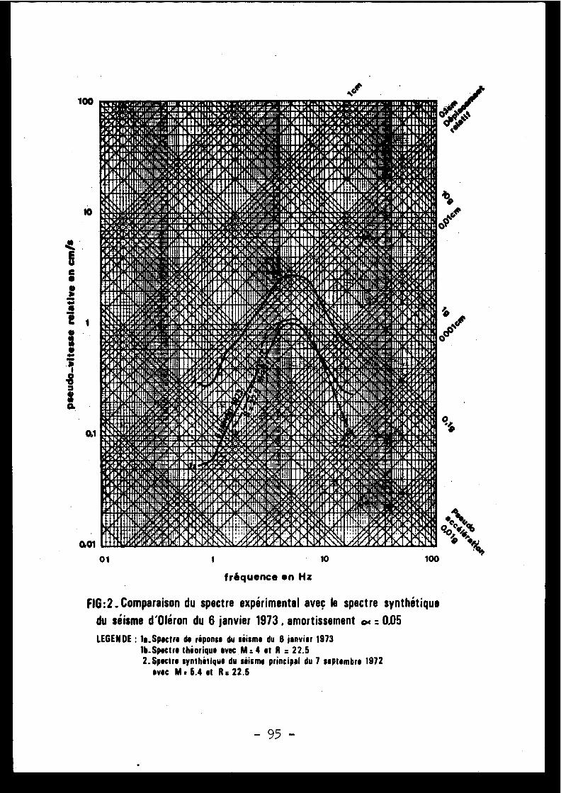
N1: ► : .,6♦\{:r .. .1, tau, Y1:r . .111\\14 .`• .~.Q .1JI' .W . .tut nn •rd .II.
i :'' •r, 1Kt)Vallrr. 'V:0 1011 ►•YV1a101r °• . : :IYGt'JIV,w U'li1.♦ M. .1r1 : 1 \SII'o v;v'VJ1N,üü'' I." It :Na :1 ,0tl : e40' .!r4 NP'JIN w'u •lr '111011moiIt:9 :;4~A' ;iUr,1111 M rIn11 .11h'Ih ► ,;v:0.';s• ,Itlt ; A:MIP IIa!It
r
r .y'1 n
:/Balli;I.' .' .,V•
/ :• .r
r
►.d1l :l Il b
•P! ►,ri'ü
r;t'' .11 :111"'s :+. /su, ;tÿ A.~IOIJ+" ..L' t111 : 1►'.b~!~', Jilll l "~II'Ifll! .,1S .1 ,l . .
:' gp 'dllïlll G0,~1 •• I
r 1A•!h !r••(1IV Nnl ll1l! :t11,8♦
11 1•lr'11'JÎ •.
• 1 1•i 4jui
IIII~~I l1n11~♦
p1•• I .r .,Ÿ,,
cI: ',
• •V,U!'iNh
I p. • t
t•►i~,nJJ. ► i!!•.la~ll.b
rIU1~1i1Y.A, uIL .: :11I119► '~~~ . ► •
r `r Ir I i l'I ' h4P '
I r r'~Ir r
111i
or,: 'ilÎ 1' !
! % r111~I"IV ,1i1
1,
.1L!l
I4
±
1 ;, ww9
1i.►i ,IJ
• l
r!R ►~!!ç!h'~Iitii? um11111I:~~ir. :»Ii ►.. ih,alll~
RI111i ► ,IIr .► ..1+w111oiiitf .111'
1Ii ~9,I
/gIrdl!lll:lh?b' I . tha41I1IlIPA. d/ . !gig1., I :11t : 11' u,' I:1II11IL0/ :I!1g e11/Y!l%:111 :4 il
0140/a'0 t l'11IPIIA!IhiIu >G .i ,l ' Ii~1~1 1 .b .l~ïh11&IA 1 III itI I 4 Yi,h!~~/ .I~it;/l'%il'ii Ih 1dl I,
1î ;1 ~~ p l .l~i lti 11,► 11 ►,1 ll .u
yi tr '•:~ ' 4l /Il 1 :11t '►. 1 r11II/, .
.tt 11 1 I 1,1 11)II 1 I1h I : yl ; i •t ►' jIÎI~1tI'i~~itli!I liI'Ipi ln 1~~I~•'/• ;0 :0 :I ÎQ 1111;~ ryIqir ~• ~
t
Ii . . 1
p L
►
11
► .
/ 1
,
•
r .t1
r
r .
r 1
I n'
L . .
Iaf; ;l1!dtl!NhI,f!sr'~d~ ; .a c : ;~lalt► l~.il;rll~!II !I~! , ►ÿa. .♦ ~~~i! ;III► l~aialâtIhL I
'~'
► it =~~ i
I t
t~ ► ~''I V
y
thd' y p'It'
{n
►,' 'i 1 pi
I
I ~J1
It +~
► 1
1
,r«
i► 1 ►
y
N
I
I► , ► i Y 1,tE /.Jl~tttl~li
ate .n~ ./1 .i .A ,,,ii .IIIti ~1 .I . .o ~ e ~
I/l lu
I
.~ .~ .it•" .i~Y .. . 1\~
t'•!'l'• r „~,
•1
~~' ~r
r•t
, 1• ►
i
d fr •r, t•
.
r 1' 1>I)
Ill! IN «V •t► M4,14", i!
piMi,
1► • ~ .1 n! :
► i ,11~1
V► u .) t~ ►
~i~ =Yd1' U
/II I'I i '4 I t
`
,~~~~~'
► , (!.511i : .P.,t :11lein : ' tti gÛ1wt111t,
w!I~1~i1 . J~:~illd~u~l!!ulii
.i 9~ m{ .,tI~U5 :.4
(loti !I♦a{ : ► ••: 1 !IY.IV .IIA'.14 p'.IItO'a>t1 :r~ ► ~Il 1: .',. :1!11 ' ASf1J',A,'''rwfllh H1:ri Y11 ♦ C~,:► :t:OIY.11' If1'at . i" Q114 .1; 11 70 1I:' .1 0:
Ir, r.u,:B'r1 II :1:!11G11017r :v'L.R :III! :IIID :~21tMd1iU #: 0110 111V :4 19!tltp l, 6. ' 113 1 10r;n!111 :f
1' VAMP ti Mar: t U1, i ~ J. o u
üUNU' MU l►api 1
v
`►
VI N 1 i!IHI ,U,'; IJ' l'3tl1 1 .~ •. Ii~ 411'.i
1 IU
illil'
► wI>? ►
O Ra . ..i .1~ .bJ ; '411V1 I 431t1i .f11ii5Ilba. . 0 . t ►, 1 :a6 . lUl6►~ p l;~Igir .111 :1114' .~~•.1.1► .1.i I IUIIF"112111ï'4e II Mt! :~• u
•• . ••1 4 4. Ilnn,
•tt0 . . I
1i1G:J.
1. • v'!► •gviu'tl{k~N
Iaul .lrlll►
♦IIU ►.
,jt, ',G:.
Irt/•.tl..1n1'
! q~tt
•
04 1i' a!Iiw
II tÎ1 ♦l~/
; . 61,
it i ► h 4{!"
11111111►!L.?ME
d •, ~t1., ►IIYtN
Î 1}rill\/•
I I ~~q
I t/ '►..b.::
1►l
44 41111i. Y
I!
I~ K e
w>i ~4 lllll! ! ' Il
► '.•' ►'~'
~i b .dL41• u.
. .►. ~
h . 'a t
. 1 .1 . ,1 ►,i1 ►
IH 1 4 •1hN lttlllre,i Fo
dr.atr
: 111,'I1 n 1 H,' I~t411 / /i!~~ :1' / / :1!1 .!1! :11l1V' a'w''yHli ► /d ► / cl :
ll1!Pt1 l~ '11 91 11' I/ Î
II
lNP @1
1,
1 VIII/I i• II t 1 'I
'i
1" 1t '.
I /.i6llb /b h N1.a!f .1 .1 ./h,11 .i1! 1 h .1li Il p,~ I , .f~ .L1 ,bfiJYl t ih(1t•dh~kthh.4!L/aldl,
14 (1••
7 (I h I ►i1•t{: r1;d1
lr 1 ► /
/
I f lt 1,j
U r " ".+ .•.I'I' I ►
r l'
,
4
y U'r ♦',,~
; / • ,lu .Iilll, UI
r~ Il.iîlla111 y 1 .' .N
1.y .. ; i 1 .,1 .►11 ±
•
i~~l .
h .1iMi•9IIN~' , Gltli!r,
r V
ti
u• Y 1 ►
I
/' ,
II
~
r ♦I . . ., 11
. ,> ~,,r ~ .gg i1 + ~ K11 l ~' ► ./
1gdl!.
W
p+ w
, ::,ii 1• . .NIIf€ q11; , ;~ d 1 ►,111t, llh ? r : J. ~ ► .~'.{. ,1~i1. dit►, lilÎh
► .l: ►~ JIr~n1i!ill1,»
IV~
.. a ► :1 1 ~ .1l 4/• •1
tp, r Ir~ l•p u . ► •. \P
tll'y p• v p'Y► ' t ►.• Il,
/ '1
11i',r w '"ui/ ►
1 ' ' R'f I l ~j H
s~ 1/1
Y 1
!P
1~ E jjjjb ,► N ~
,~ /N I~
1
ij tf i1e> + r~~y.l► ' ►
►~ •t~~~~~ .ll l li~ld ~1',ll :} .1L .1~M~1âh!~Ldl~~llll~~P5e,,
;ii,i;'
..1 ,
Q
:,
:3
r! .
1Pi' :
!h,111
'1►
1 i
~jhi~~t
g A1 . `I
jl,,►"' ~llltürn
!~1
► '1 f~ lih1i
* i1 d
•i, I 'l~~
I
"p
o►I
..
h ti 1 'ti
w
,i~► . J 1!4J+1J. .1 n ~,! i♦_19 jlt.1KW Bl '',Y( 4 '' .;1111)A1 1 :1 :114\C1or' :o:rv,r.tuott, Nr,' .W :a►♦! Y 'It i, ♦ :► eg :Il'Jtt' ;ü"r,7111tti/C ► 7CU l
•? :t~ •x~i , 11111 .11=' 0 111 1%1 111! tICL r°i /r P. i! 't ii IW :d!!' ' a IItI!!i'J 4 11MV,O v`wMNIfÎI ~û U atLI~ .411 ►!ii. ' t ; 'ïliilr41.i : :rtllillll ;'d
iftIli;i; atir, Ac111r . Stili IPJ44:~~'t. iti"illluk;rhllli'' 11:111î '• ~• t . •
P.N1rl I.lila\
•~r •t/ ~• ••• N•M•itl, r ♦ r, . 'a • •n
I.' ., `Iiv nlul. l' Z19tt •r..
l â . rw
uu ► , .►. . ~a V ,p
l p' 1 Inlit sRttt ::,►.:. .,~ .v . :al,h .n "~,! .InE1.• r q V
1
1 •~
/ r
q' y►
1
hy 1
pt r • • p• 1
i' p
,I
..'•,
t, r
'111â!Îb~1~lâ!,4 ►h~IlldIII►,,.,/rr;'!`!'
►
dt, I ll n ".N ,
.'!!t:
.i!%!/'
'
~i '
i 17}~ . ÎI lié! , 1 ' 1 4 1 I~~
i i
'1 ti l i
4p , I ,i e lp ► 1 ~ a .ll ► 41[1
'
I , 1 . ' J/ r/1 H1:14 tH .mkll :m .l, ,I . .
d / . .111!lr , ~ Ih!IIn ./ .I .Jh .t1 â1 .1lA
.IIh~I h 1, ~a.l .l .i 4
• ►' ► I li►'' EI!!' 1 fib•,>•„vr p ot,• r'q ,pi t ► •1 s .► r p11► ' o ily n'•ti1 h1 I u,,, ''' r►~/!I►!
.rt ►t►,V /
`li ~tl~1 II~L•I•!•! ►fifl .l
~ ► • 1.1 . 1. ih ïl i.IrPr It ► 1~ i .11 1r\
q . . Ir J1► 1 ► ~ i
.
tq
111'a A ' 1 ►
i
`/`Î
vl
p 1 ,1n ~lall l li~tiü~llll!~r!!' ~~ ~ .~'. ~ul►n`; : ` A' 1111!!ll~a,~l; t{ :i! 1 1.I,Ili; 1' Iat1,'
i ll q1
d 1• !l i tiij°P
lut i1luP'~ 4p,
4+â4
b~
.40'0..g â►:Î ►► lt:xe,,t H111, .uP,r,' m!û l ft éi~ô~i ►, '
44 ke
11P~Il 'O,I" •~ii ~~~4~
~l► ~'i i pc/!h1 1 j !
i:i l !Îi 1.,,41! gg t,,,~o t ,Xn
~ IJIIj*~~JI'1961t .` 1,, 1 13► \ :;~
,q',4t :1t/!1_'t
11t6U1 :Cai1fl .'t` ► :o:MJi:WJLI' ;ol'd' .111.t, n 11:/7 :•1 %LIU!' :1'P1r.u'Ille
°!U' 1 11 ► 1 1 1 :ac1 :r.4,, ;Irall,.ur. Ir.as.r.'oet ir,i.iY.Iltuttt n,rnaa,ri'ii'e.' .,V7:t rnur.g IR1 :,C 1? .11e .ii!I'•►. :►.:1', :r.auI . .r;IIr Y :IIl
1i1 fVG.:a:v_1o Mail 1! Xi 1 ln 683111114.111011CtAt' ,N,'3e .l ,jl1 lUiûr.1'llli7.011i!1 1: 'i ' 1t.4i 'dp ltl" y.ltti:i>fu :50V'4-T.Er.~ ritilIM" I1, l üi!21111tU(M9:~.1'~!i"ïlfll}!"I IW? .'dl1i5lit:• •y•y 1 11ï .1 ,,~,~ry Nal~q
`eâi -rf•«.
v •M 4 ♦IW
(I
► jr~,r •I . .~• Yr• .I'',il~iiIô
.,iIr
111♦
t •1/.1 ;%., .► ., l.}►.' .!~ÎiulY .dnv►
...fr• ►..~i. .„
..a .fA .w . .1~ Jn~l~iiu .r . J .►,~rJ:a►.4• ►uitJ . 1
1,•
!1i ;•!. '
!I
MIRfi/' r I t ► \/'
1 •1A611111111►,
t r r ~ r
Init
''llF!b~~
ire,1~;►~ ;w~
/aPe`!,tN~O..lr. d
' ;
►~l.:li ;:l+llit1 I ►, :!.1 0. :11:W1!ti 1 111 II 1b 'ti, :ilIIPl' ~•N'1!:Pli!r1:11i'I''tî ' Iq'i~II1 P#~l Poe ; Ppsils :ti!Y,t ;114:N [W:4;111 it ;',i ►.it :!!îti,llli •q1 1 M .ti ! r~ ~/ .t k .~1~11 ~►ih4N' .IÙ 1 Wé 414, .~~'1, . 1 1 1N 11 1 4aItaII'lü i Iü l lb ai . l y i• ~~~i .!!l 1 ,
/ tYY)) 1 1 P Iby@GI~!~ Y p JD,
.•, .
II . .II''i►/&lithill.ll3ll~h i1►J{ r r jrII ''►.►, f! :ll Y 1 l E',1iU!ht"'I 8 h u Io /ll .1!ti►! . • iO
l .IU,rl~,lt aL ,I 1111 111~
a' ~« ►b\ yi
1
1 ~n Ï o~ej d~'~ (1
/ ill
t
r,r } ►4\ >.i; r Il ! .~► .~ .~ .,tll .llll .~IlL~i :lia~. ..: 1 ► .,. .~ .lil
#1~1 Vif ~jl,~~p'1~~►~1~~1~.~j~N ►1P, ~
~III~42
y1 1►1t~/1yrl~ t
~~~~1Up V~ , ~~ ► ~, . ,
~~.5~ 111 .i 11 .
Jr
.n u~ - 4T,i~~/i U1i s ~2 ,p ..y .,.l l>"0'' r ' I I► y► ' ZI y11 ► '
~
"
I'f ~'r r d► • '' 1 1 '1
fréquence en Hz
FIG :2 . Comparaison du spectre expérimental aveç le spectre synthétique
du séisme d'Oléron du 6 janvier 1973 , amortissement « : 0,05
LE6EN0E : la .Spectre de réponse du siisme du 8 janvier 197 3
lb-Spectre théorique avec M :4 et R : 22 .5
2 . Spectre synthétique du séisme principal du 7 septembre 197 2
avec M,6.4et Ra22 . 5
100
0,1
0,01
1 10 10001
o
- 95 -
5 .
EXEMPLE D'APPLICATION PRATIQUE
,Une étude du risque sismique a été effectuée selon cette méthod epour un site du Sud-Est de la France . Une étude sismotectonique détaillé ede la région a été effectuée à la demande du Département de Sûreté Nucléair epar le Bureau de Recherches Géologiques et Minières Figure 3 . Les principau xséismes de la région ont pu être associés à un accident tectonique affectan tle socle sous la couverture sédimentaire . Le SMS à prévoir peut être évaluéà partir des données locales . Le spectre correspondant est représentéFigure 4 .
REFERENCES
ROu E, J .P ., DECHEVOY, N . - Sismicité de la France de 1940 à 1950 ,Ann . Inst . Phys . Globe, Nouvelle série VII, Troisième partie ,Géophysique (1954 )
/2/ ROTHE, J .P ., DECHEVOY, N. - La sismicité de la France de 1951 à 1960 ,Ann . Inst . Phys . Globe, VIII (1967 )
/ / RO'IHE, J .P . - La sismicité de la France de 1961 à 1970 ,Ann . Inst . Phys . Globe, IX (1972 )
/4/ KARNIK, Vit . - Seismicity of the EuropeanArea, Parts 1 et 2 ,Dordrecht, D . Reidel Pub 1 . Co, Dordrecht (1969, 1971 )
/5/ BARBREAU, A ., FERRIEUX, H ., MOHANNIADIOUN, B . - "Les études sismologi-ques effectuées au CEA dans le domaine de la sûreté des sitesnucléaires", IAEA, SM 188/17, International Atomic Energy Agency ,Vienna (1975 )
5/ LYNCH, R .D . - Response spectra for Pahuta Mesa Nuclear Event ,Bull . Seismol . Soc . Am . 59 6 (1969), 2295-2309
/77 JCHNSOI, R .A . - An earthquake spectrum prediction technique ,Bull . Seismol . Soc . Am . 63 4 (1973), 1255-1274
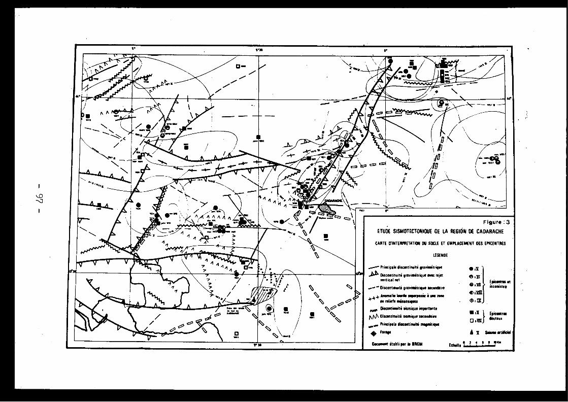
Figure : 3
ETUDE SISMOTECTONIDUE DE LA REGION DE CADARACHE
' Principale discontinuai ipavimétftque
Ja+' Discontinuiti grevnnétrigee avec nu lvertical ne t
"' Discontinuité gravimétripre secondaire
* F Anomaliesassa
. iu à une see
Discontinuité sismique importante
nM Discontinuité sismique secondaire
va Principale discontinuité magmatiqu e
forage
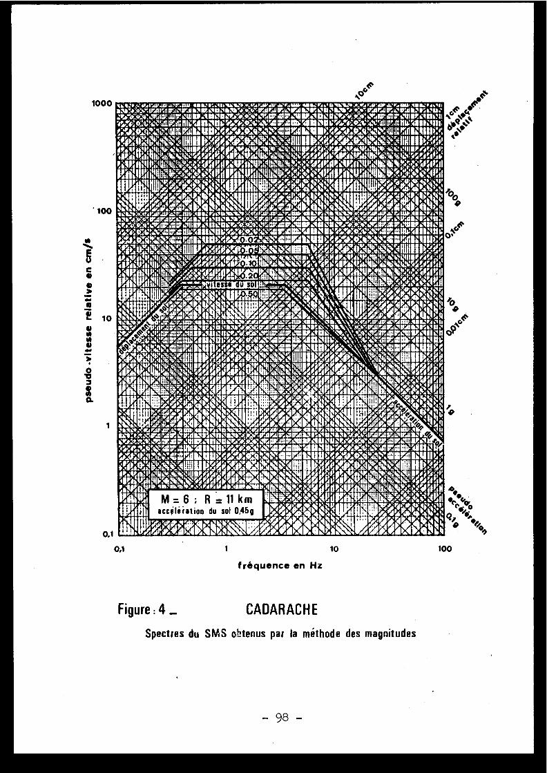
V{:► -: Yi1LYdw :u7r.nu u~ rw .or . ram ima:r aoa~.o :.:.ir~►~ *work:s. nt, ta . .• ua ,ul'o :os.°.irluri d@".10r.11IM~\11010h'A:Ÿ4. IrtlriNa.01MI N01WILMI .►OY;irprAr.01'.01VOii'u :.`~.ip;ü V. .!Mr pN!~WI6N ►:g ldag w0~r°o .v~► tl0!itlAldr'10d rnhpC►rw:uo.~w~gC ~1 ~tl1~f ► ~q ~!1 14 i~CCS :411IP.PAI ~ :i A11 ►111111 'A!'v. ►~VIWA1C!AIRgA11011irr!vCA;AN .'''dIIIII!,MA1I61111 .G►~,►.9..q"+~~.!tll~{!'• III►{IfI ►.G►•i~/!~1.O.Y!!~.9
y1C~CM. ~ ► .N...n!!i.rr►'.'9Cl~M'~111►1111! .!',
II~!a.: : .~d~:~~~~lllidb ;~ ~w, ABi~~d► •~• dJ. 6 ~1~4~1 ..~~~t4~~W11~%a~ :~.a~:.►,,, .
!1.Y b
~l~
tl
1
lrYd ►. :►
q~~~~► ~dlli~llll ~;~~~n~ n~
1.•.ri . ,11~N1!~dl, •Mâ4i~~Î~:1 JaÎ .~ .i~ i ~, N6 ./'rdrld .N`4ilth, Vh1:
,9A.14:~N.,~
5s;s
LA
t:il ► 1!In~;!gl~~! ~v •
Nb~PJ~I .,~~',rrp~
►. .Ur.n~d i,~, .► t~I~,~~;r'.",b _Y•.. V r,..d,►1 d.,d ►. ..U;•, li l . ,9 •9 . •p tlS•," , .Y•~•.•, ►dr,1 P
fa%~ ► !!'_
I~Ia~lUdi,~,r.i~yl~,~pLLa~,~bt~ : . N
~a~i ►bi~•~C~1~lil`!f~•~•Ii11~~~.r~Yr .1 ~. y •ylg~,"r. rd ►~• .r p r
J~ ►bi~~i~~r~1,n .V .1~11.`tl~V.~r~ ~V i• ~.4~r4 ~ ►Vi~1~ .~~iI I~ '
t~~dÛit•,r
~~'r~''a''~►h ► 'YV .
,o dlhl► . .r•w~' r~~
.~ .~a •,w .n
a y ►-y~r..V .v . .Thu .
ryP.wr;r•rd ~
~r►m.n. .a
a..bh ► •~ r
.. ~'
. . 3JCrY~~.;Q;
br/'
4rtl~b'
• A PiLliPl ►~i ~ \
4t,Od
~~. .
►AIOl
441.'O tl R
Ts!Yri~rVYe~ l i:tl1id~~.V ►4
1 ►M1/
b1 10,~Q lyl
`'
AAtl•./rd...dÇ~~
i~M ► •tlAL:ma:0A
1P •' I►•1V h
b
Ul.V:V.d,rJi' .wga:DJittw :4•I r9►lUtaY1D :KVrI~tl! .11r .4 'rrRlh .d6nillIO ►L0.nelit:W.iR.M:ratIpIl1Jr~ .Y hah:Ju 1Ki1 :!JIIC:►u.ai:i'iu /.tft;t-g1r .Or,alr .OptJ L1110► /121O.t~..IO" rtlri4I05Y\O.dl z/: '111 :CP►.:a0:114: W!Art.1ttaBiSlll:a►►A0 CtIt'r01► iISON..M1Y. .rnOYC►. .''or0~Wr p ir.~gIOngtgH01101151,!;,014► !•; !'i1tlIIC: g1~A11rrGCiv~h d:. 'r: ! iCIIIh:WEp~~d11 ►111~i►v!~:N~ti' •+~!~IIICr:~it11 ~111i~t1 4
Ci.C.O.I.r~:!rllIMI0111t:! o.0 zd~ ; IC lr..tl1►~n ►:ram~~►:Nr~" ~!.!IIImNJiilClii l ►.;:
s_1JI~ b tl ►d811lIKu., ►~.._ .• d~pb dB U w I" , ll+e
~Vsi
Iili ., Nld l
I F;',dht0liot
! ►,~b41le ~ ►"~Pr o
./►..I4b.IV •
• afor• a4I•►. i
•!~4 .g i.~
~i i0e, 'g%I
0r10alt
ALlis
h dlAp' i 4h
44'II=EZid :, 1 1rel:IN
►â '
rrd
tll!Ti
. .
ini. .thtla;,►%_-'
,
u P,,~ r;
iA''z"P
S ►Y Po . ► .
a►~~14►4 .1b
1"•SIJ ►. ~
1~ ytiy
iill:ir ►. aud
eas e►
m.
~•so
•
•.
vv~A~WNEI
N'rdp ► ►,d..4!,n&\No i
iié.nn,.1► 1' . ~ib ►~..'~ti
/'~1~
.
.iOV. ~ "\. .Nrü.itm
MIR
'
p , .,4
: A
i'
~','ei4*q!4O ►~4
roib'~• , ►r s .
got;,~rrinho ♦
r~ ~
,1~► ~1
r'
n1
U
• ~~~ 4P. ,+ w` iti tl►
law.11 h ~b' A L ► •~
, ► •Vnb 1
~,aidbll .
t•~u
r, .
/..~~~~~~•,/4ti414,1~1 ►
e, •yC. .
orAA
Itt.i.
r aw
~ÎPr
db . ~►
•V~•` '
►rye\~
.N., ►i\~' . ..~ri0. ...,ol,so.mist
~
i;,► r,*44;
► hubinti •
4UN)?. b .01```'O,o:
etler,W.idritlv r dpU :utt:rAc•h
Ritir .. :IC•til, :qa: 1 .•rUd`4V. :CA/rl0 : g r:o:rrfW :ga►MI.
~wi~ttsrum p ►nnn:+ulna► ..~•rarw~~~lr!~dem .~tas► .~n..•~iirum,,CiVSd~ .u: .,u~•.v~.rsr~q•.aw. .rm: a .•~w.aa~.n..~~~• .o~, . .~lruw.mer ►~ar;a• .tr.~au.
~d Irw~nla►.•tn~a.~•.r
67v . .1. ...~ .., . ,rtottainc.s .rn rV ~' r 1 ► r,al crsylibr_•~,•o~~~rlr~~.t.,,% . .4. :► .►.~dt!ir' .vr .aitb.4i11►IgC~ `'N'q~► G 'IM11111 t'f►
p9t; .11',t4.
~tirtt~.1 ;!11111 trM111Ci~t\'. i•..dt'iri
Yri v 7nillinvioPd.~~►
. ►
i . b ~e*cas
d '
. tya°tlllltlwa1 1
i
1aUwwI 0°rmop.II
r
~
.r• i .► r lye.NeM
~
i0` ~ vY'
i~ r
~~ 'P .~
.r ;U'
~•w, tN, .,• 'lill~I~.t&. ~~"~4.44 .
. . .~11Vr1•
q~l h+ .+ ~telnl~ 11 i~
r..l~I .IA b .
OMON.\As. AIN ii,!!~y! .I.l .lJr4
df,~o~
h~~i
.'U' 4~" N~~"Md' Y P'V.i ► ' , ov ~i ►.iUil `HI► 4 `~ ' +'~Q~NII
i$h
4\.y. .' 1 I0fip.Od
4rd' m a
`V
ridktia►~►L~ .
p
, 4,1
'P lAteo
r r '
A..
►°,Yt►
0,
4i.. ~tV4 .
r
=iJ~ •1~►iatlla~
,r ~~an a
~p
Yi
. . ~
''~ P
ab.ISNO :ot rm4LI &MIS airAMM''Ir :.,VdParmr,~rsaut A .it
yi/a~'~.,.at.a•.,ewrmum~' q,PAUD :uRr
~r'.gri1 /ri► r'.d~.t r►Yq~~.t►► .IrAr 10; Pe.01t/ .S1a :1031 Y,R.4.4r'.drAVatglWAII . OGirr.th:000OVIItlLMOU10.yilYaC►rfd'SeWiNt1Y:iMEMIl241101ICte4e .t. ';O:dUCi3mIP!gUlUsl.• ,rima ;4~`ilCll illmoinr`Iugnoteiiâ~,'ammilunaugo 1:1►:.s~'~+►,wittamtni115 P/
:6t:%ttNIC41121rdlMlliC4 .05CON216MIMILIU111CCCO!4X .01ti!=6111r' MUM► . •• v vbr \~!'• .~ . . r~ V' p ~~Atir q r r ►♦ r r •r y ►~ ~ ► r•/► ►
/~:N~,~a v ► ; ~, °,~I I'r~, .li ► 'yr t► ` ` / r ,p P1iN' ~b' ~,~s
~~,r ;, p
ldf.ga h` ,irir+11k.mko'..aun do:unr& rd VrliNP.gUÎtiW ô dÏ!'+ood=14~a,P, N
►. .I
M = 6 : R = 11 km IIIA.r~
a► •gw4,yeviN40
„d..o~Jhd~:rad .l liW _,►d~ ti.I
accolé iatioA du sol 0,45g t~ ô ~~q►.~0+~?ü ~r'~..4tAit ,. .4
kli~'1 â: iblbAsk A . ~±/d,tat /. OAtA9é4~ô
loon
100
1
4''O •
10
1
10
100
fréquence en Hz
Figure : 4 _
CADARACH E
Spectres du SMS obtenus par la méthode des magnitude s

Discussions
C . WEBER, Franc e
Je souhaite préciser que l'esquisse de carte sismo-tectonique de la Provence présentée par M . Barbreau est undocument encore provisoire, qui figure les principales infor-mations - très cohérentes entre elles - provenant de l'étudecritique de la sismicité historique, des mouvements quater -naires, de la fracturation du socle d'après la prospectiongéophysique . Une synthèse de cet ensemble est actuellemen ten cours d'élaboration, suivant une méthodologie nouvelle .
J .P . ROTHE, Franc e
Commentaire sur carte présentée par M . Barbreau .
La feuille Marseille à 1 :250 .000 est un bon exempl ede carte sismotectonique établie à partir des données sismolo -giques (épicentres, isoséistes, carte d'intensité maximal eobservé e ) , des cartes géophysiques (gravimétriques, magnétiques ,isobathes du socle), . des cartes géologiques néotectoniques e ttectoniques tracées à partir des photos obtenues par satelli-tes ; sept provinces sismotectoniques différentes ont pu ains iêtre distinguées ayant chacune leurs caractéristiques propres .
[2 .5 ]
EVALUATION QUANTITATIVE DES RISQUES SISMIQUES .
D . COSTESCommissariat à l'Energie AtomiqueGif-sur-Yvette (France )
Les aires macrosismiques des séismes survenus en France de 1901 à 197 0sont sommées pour obtenir une statistique des aires frappées à divers niveau xd'intensité . Bien que les séismes de haute intensité soient très rares, onpeut proposer une évaluation globale du risque sismique en conditions mo-yennes . Sous réserve que les analyses sismiques locales ne changent pa sfondamentalement cette évaluation, on trouve que pour la France la résistan-ce est facile à obtenir pour les mouvements de probabilité 10-2 par an, e ttrès difficile pour ceux de probabilité 10-5 ou 10- 6 . La même conclusionparait s'étendre aux autres pays .
The macrosismic areas of the french earthquakes from 1901-1970 ar eadded in order to obtain a statistic of the areas subjected to several le-vels of intensity . Despite the scarcity of high intensity earthquakes, on ecan establish a global evaluation of seismic risks in mean conditions . Un-der the provision that the local seismic analyses do not change basicall ythis evaluation, it is thought that earthquake resistance is easy to obtai nin France for ground motions at the level of 10 -2 per year probability, andvery difficult at the level of 10-5 or 10-6 . The same conclusion seems va -lid for other countries .
1 - INTRODUCTION
La .protection .sismique des installations nucléaires est généralementdéterminée en choisissant, parmi l'ensemble des agressions sismiques consi-dérées comme possibles, deux niveaux de référence S1 et S2 . Le niveau S1peut être dépassé avec une probabilité de l'ordre de 10-2 par an et il es tpris en compte au sens économique : l'installation doit pouvoir continuerà fonctionner . Le niveau S2 est celui pour lequel les fonctions essentiel -les liées à la sûreté des populations restent assurées ; en réalité, ondoit combiner les probabilités d'agression et les probabilités ' de comporte-ment satisfaisant sous l'agression pour arriver à une probabilité global ede défaillance inférieure à 10- 6 par an .
Les niveaux S1 et S2 sont en général déterminés à partir de l'histoir esismique locale et d'observations sismotectoniques, ins aborder l'apprécia -tion quantitative des probabilités associées à de tels évènements . Les rai-sonnements déterministes se ramènent à des choix entre "croyable" et "in -croyable", ou à des règles forfaitaires concernant en particulier les mi-grations possibles des foyers sismiques .
Lorsqu'on connaît les structures séismogènes susceptibles d'influence rla zone considérée, on peut faire des hypothèses sur les densités de proba-bilités attachées aux sources sismiques, et moyennant l'utilisation de loi sde transmission aboutir à des probabilités locales de mouvements . Cetteprocédure a été utilisée [8) pour dresser des cartes détaillées de risqu esismique dans des régions soumises à des séismes nombreux .
Pour des régions moins sismiques et dont les particularités apparais -sent ainsi moins clairement, on ne peut pas connaître les structures séis-mogènes de manière assez précise . Les données historiques relatives à d egrandes surfaces permettront cependant d'établir de manière motivée le sfréquences moyennes d'apparition locale de tel ou tel niveau sismique, dan sl'hypothèse d'une distribution aléatoire uniforme . A partir de ces fréquen-ces et du nombre d'observations, on peut passer à l'appréciation de la pro-babilité et de la marge d'incertitude correspondante . Cette probabilitépeut être appliquée directement à un site considéré comme moyen dans la zo-ne, mais doit généralement être corrigée en fonction des particularité sconnues du site . Le jugement du séismologue intervient ainsi de manièr edifférentielle et permet une appréciation quantitative des iisques locau xplus motivée qu'en l'absence de toute base statistique .
La présente communication vise ainsi à définir quantitativement l erisque sismique moyen pour la France entière .
Dans ce but, on évaluera les aires frappées en France par divers ni -veaux d'intensité sismique, dans une période aussi longue que possible . Sereportant à la surface de la France, on convertira les aires obtenues e nprobabilités locales moyennes d'apparition de chaque niveau d'intensité .
Après discussion sur la validité des résultats, on comparera les ré-sultats avec ceux publiés pour d'autres pays .
2 - UTILISATION DES DONNÉES SISMOLOGIQUE S
On dispose pour la séismicité de la France de données très anciennes ,
- 101 -
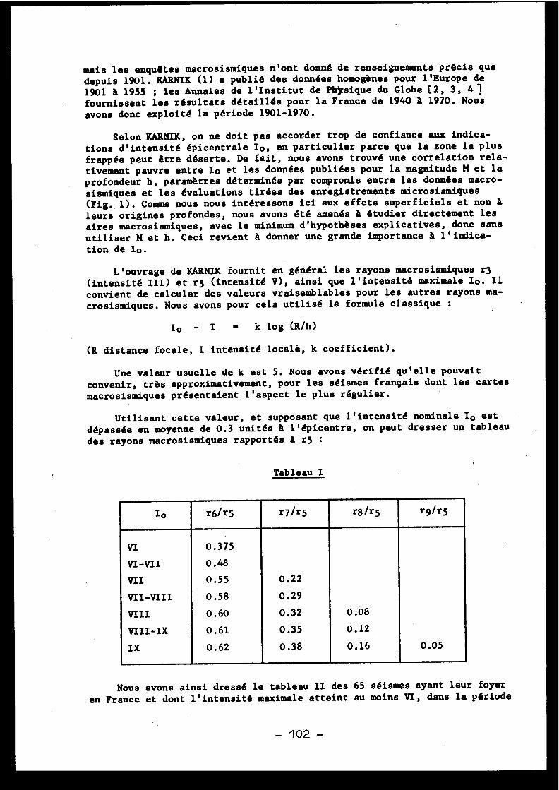
mais les enquêtes macrosismiques n'ont donné de renseignements précis qu e
depuis 1901 . KARNIK (1) a publié des données homogènes pour l'Europe d e
1901 à 1955 ; les Annales de l'Institut de Physique du Globe C2, 3, 4 1fournissent les résultats détaillés pour la France de 1940 à 1970 . Nous
avons donc exploité la période 1901-1970 .
Selon KARNIK, on ne doit pas accorder trop de confiance aux indica-
tions d'intensité épicentrale lo, en particulier parce que la zone la plu s
frappée peut être déserte . De fait, nous avons trouvé une correlation rela-tivement pauvre entre Io et les données publiées pour la magnitude M et l aprofondeur h, paramètres déterminés par compromis entre les données macro -sismiques et les évaluations tirées des enregistrements macrosismique s
(Fig . 1) . Comme nous nous intéressons ici aux effets superficiels et non àleurs origines profondes, nous avons été amenés à étudier directement le saires macrosismiques, avec le minimum d'hypothèses explicatives, donc san s
utiliser M et h . Ceci revient à donner une grande importance à l'indica-
tion de I .
L'ouvrage de KARNIK fournit en général les rayons macrosismiques r3(intensité III) et r5 (intensité V), ainsi que l'intensité maximale Io . I lconvient de calculer des valeurs vraisemblables pour les autres rayons ma-
crosismiques . Nous avons pour cela utilisé la formule classique :
Io - I = k log (RAI )
(R distance focale, I intensité localë, k coefficient) .
Une valeur usuelle de k est 5 . Nous avons vérifié qu'elle pouvai tconvenir, très approximativement, pour les séismes français dont les carte s
macrosismiques présentaient l'aspect le plus régulier .
Utilisant cette valeur, et supposant que l'intensité nominale Io es t
dépassée en moyenne de 0 .3 unités à l'épicentre, on peut dresser un tableau
des rayons macrosismiques rapportés à r5 :
TableauI
Io r6/r5 r7/r5 r8/r5 r9/r5
VI 0 .37 5
VI-VII 0 .48
VII 0 .55 0 .2 2
VII-VIII 0 .58 0 .29
VIII 0 .60 0 .32 0 .08
VIII-IX 0 .61 0 .35 0 .12
IX 0 .62 0 .38 0 .16 0 .05
Nous avons ainsi dressé le tableau II des 65 séismes ayant leur foye r
en France et dont l'intensité maximale atteint au moins VI, dans la périod e
- 102 -
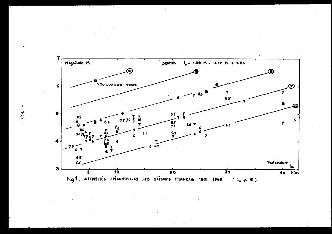
5
4
3 s
io
20
3o
Fist. INTENSITÉS EPiCENTR.KE3 AES 6ii6MES FitANCALS 1901- 1969
( 1 0
6 )4o Kr*,
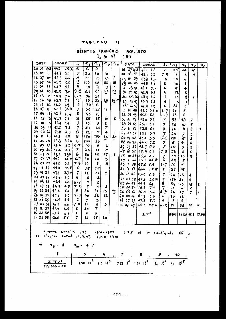
TABLEAU
1 1
SÉISMES FR1NCA ►5 1901 .1970Io
VI
(6 )
DATE coo4D . I. 'L 5. t i ~ 7 't 5 .pATE cooRD . I. hs ~6 )r 7.20 04 1901
13 os
0 1
IL 07
04-13 07
04
10 04
05
11 04
05
15 0 8 0511
06
0914 12
0914
07
I IIs 09
I L14 Os
1 316
lo
1 38' 09
1 7
23 09 U.
t9
11
2 3
01
01 25
21
07 252c oq 2$'
.50
07 2 61 7
02 17
24 07 27
-19
11
2 709 01 3004 07 3019
05 331z os 34Ig
03 3 52.8 09 35IS 02. 36 .17 04 36
17
12. 37
16 02 38
.11
06 38
443
7 5 (e)
441
5 .0
44.942. .13
0 . 64-4 .3
5. 145 .9
7 . o45 .9
7. 64-3 .7
5. 446 .0
1 . 941 .5
0.4 W42 .8
0,1 W
45.9
5.846 .1
1 . 6425
3 . 242.8
2 . 541. .8
6 . 848 .9
4,81I146 .o
6 . 146 .4
2 . 1
49.2
1 .9 W49.2..
1 .C W
44.2
5 .248 .6
0.5- 8147.6
2 .9 w45 .4
6 . 544.4
6 .444.4
4 . 844 .6
6 . 645.8
0 . 044 .4
4 . 046 .o
6. o
44.6
6 . 6q4 .6
6, 650 .8
3 .6
67868
8- 96-710
676877886
6-7786-1
7- 8C76
6- 77- 58
7 . 86
7- 86C
7
63 o2s
10 01 0
12 0so6 03 05 050Zs
1 0s o12.
15 0Zoo
10
2. s
8o401 0
75-¢p5s7
4o
4o
71 120J 295
21 6I S45
6802.4
. 351 1271 91 55Ro
7
'100
2 05
1 4
4 8
22
C
28
L 2
2
s4
2 62 33C74-
6S
68
303
5_0
2.0..
1 1
. 82745S
zS
25
3
9
215I2
3
Zo
281
30
163t
Z
130
6
10
18 . 57 1939 44.6
6 .8 87- 8
6666766
6- 76- 77787
7- 977
7- 87C
C - 7c7787
8- 966
8-9
- 55 ' Io1
Z
7S4
.32Z3S3
45/52r
/2
1
S-
4-
5'
08
/2 38p9 04 592.9 04 40%o
og 4 12C
1Z 4 550 094 62.7
05 4 7t3
1 .4717
01
4 82Z 03 4931 0! 5028 06 Sc)3o 11
5 ;07 02 52Os oy 5208 06 52
25 09 5208 /0 5213
/0 53/5 Z 5620 3 5820 7 TBZr Il SB01 01 59Os 04 5904 0? s a2s o4 6z.29 08 lyIC 07 6713 08 q
45.1
5342 .8
1 S44.8
6 . C4S .4
5 .342 .9
o . t43 g 4 .645 .)
5 .842 .9
O . 943 .1
0 .8 W44 .4
6 .443;0
0 . 243.1
2 . 643.8 &445.J
0 . 743.0
0 .044.2
5. 248.g e.o48 .9
6 . 043.o
0 . 243 .J
0 . 4 W45,5 5. 546.o
-1 .2 w43.0
0 .3
48.o
4 .0 W44 . 946 .2
7 . 44S.o
S.e42 .9
o .o47.2
5,245.0
0 .7 W
r s
51 0I o12.t3
3444-5
103
st
2. 420! 3
3 32 51 42 0299
15-232 31 91o364 o/5 03S1 1263o8
956
1 91097s
4-78
10S
/ 5
/52S254
1 71 Z4
70 3 5
1698022$o7 9513 2198
A'~,
s
KaRwiK
► ) ,go % - 195S (S
et
r
souli4nsâ5 Srtt
rt ' .
r .ii
RoTni
L1,3,41 194-0 - t97o
*
•L 9 a
9
;IC s 4
?
I S
G
7
8
9
1o
7.
r t.' 8
lô1
13
1O
7.75 103
1 .87
10y
1 .1
10 '
4 .1
10-7SS/ 600 . 70
-104 -

1901-1970 (70 années) . Pour simplifier les calculs, on a considéré qu el'effet des séismes venant de pays étrangers était équivalent à l'effet de sséismes français sur les pays étrangers ; on a donc pris en compte les ai -res totales dues aux séismes français . Dans ce tableau II, on utilise pou r1901-1940 les données de KARNIK pour les rayons r5 et pour les autres ra-ydns soulignés ; les rayons r6, r7, rg non soulignés sont calculés d'aprèsla valeur de Io au moyen du tableau I . Pour 1941-1970, on se réfère direc-tement aux cartes macrosismiques .
On a également calculé la somme des carrés des rayons macrosismique spour chaque intensité, ce qui permet d'arriver aux aires totales frappée spar chaque niveau d'intensité .
Pour le grand séisme de Salon-de-Provence du 11 juin 1909, KARNIK don -ne les rayons macrosismiques jusqu'à r9 : 9 km ; on suppose arbitrairementrio = 4 km (f) .
3 - RESULTATS
Les aires totales frappées sont divisées par la surface de la Franc e(551 000 km2 ) et par 70 ans, pour obtenir les fréquences moyennes d'appa-rition des divers niveaux . Ces fréquences sont reportées sur un diagramm een intensité et fréquences cumulées (Fig . 2) et permettent de tracer le scourbes suivantes :
. Fréquence-intensité en considérant tous les séismes ,sauf celui du 11 juin 190 9
. Fréquence-intensité en ne considérant que le séism edu 11 .6 .1909
. Fréquence-intensité globale .
Il convient de se demander si le séisme du 11 .6 .1909 traduit bien, surcette période de 70 ans, le risque moyen d'apparition d'un séisme de hau tniveau . En réalité, il semble qu'on doive remonter à 1564 ou 1494 pour re -trouver en France des effets équivalents . La période moyenne de récurrenc epeut être de l'ordre de 300 ans . Pour cette raison, nous avons décalé d'u nfacteur minorant 4 la courbe de fréquence correspondante, pour définir e npartie haute la fréquence d'intensité globale .
Cette courbe de fréquence peut être considérée comme une courbe d eprobabilité, dans la mesure où l'on considère un site moyen ou un sit ed'une région moyennement sismique de la France, avant toute étude de détail .
Les séismes atteignant le niveau VII apparaissent en réalité presqu eexclusivement dans les Alpes et les Pyrénées, sur une surface de l'ordr edu sixième de la France . Pour les régions sismiques de la France, les fré-quences moyennes sont donc à décaler d'un facteur majorant 6 . Inversement ,pour les régions les moins sismiques, on peut décaler la courbe d'un fac-teur minorant de l'ordre de 10 .
(t) En réalité, une révision récente des données sismiques correspondantes ,connue après rédaction, attribue à ce séisme une intensité maximale IX .
- 105 -
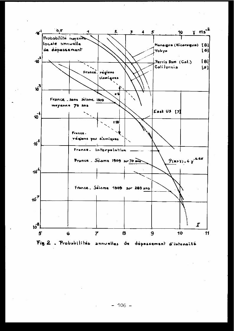
ro
10
10
10
10S
10
1o8
Iô.s 2. 4 5,2.
Probabilité moyenlocale
a.fntlvalle
da Ô1élasbe%Isantf1ar a gua (Nicaragua) t 8 1
1 -roilryo
[ 61
'Perris Dam (Cal .)
(81•~
France. nigtonssLsact,=ues
n `
IN~ Cali Fornia
L
1
Franc& _sans sitsmt 111911009
East U3 (7
me /ann . 70 art s
. \ `%6h„
Francs -
riss pw
10
savntquss
I
N
France_
► r•rerr.l .t;en
_
-
Francs - Séwme 1900 sur70 aine
1
?(a>1) s 4
6•es
frlsnr.e _ $il.stns 1909 swr 280 arts
5
6
Fis 2
'ProVab1 4s annuelles ds dépsssevne„1. d'in1•enau.ts.
9 1067 11
Ceci conduit à des évaluations moyennes des niveaux de référence S let S2 .
- en région peu sismique française, l'intensité de probabilité annuell e10 -2 est à peu près de niveau V, tout à fait négligeable techniquement .En revanche, les probabilités 10- 5 et 10-6 correspondent aux niveauxVIII-IX et IX qui conduisent à des dispositions parasismiques soignée ssi l'on désire, par exemple, une probabilité 0 .9 de bon fonctionnement .
- En région sismique française, la probabilité 10- 2 correspond au niveauVI-VII dont on peut se prémunir facilement ; les probabilités 10- 5 et10-6 correspondent aux niveaux X et X-XI, trop forts pour une probabili-té 0 .9 de bon fonctionnement avec les dispositions connues .
On a reporté sur le diagramme des valeurs conventionnelles d'accélé-ration selon la corrélation de TRIFUNAC valable pour des spectres de séis-mes forts, qui ne sont pas rencontrés en France .
4 - COMPARAISON AVEC DES DONNEES POUR D'AUTRES PAYS
G .W . HOUSNER évaluait en 1969 (5) la probabilité de dépasser une accé-lération donnée en un site moyen de Californie, en supposant que les séis-mes étaient distribués au hasard dans cet état . Il estimait à l'époque quel'accélération ne pouvait en aucun cas dépasser 0 .5 g . Ses indications son treportées, après transformation convenable, sur le diagramme intensités -probabilités (Fig . 2) .
H . GOTO et H . KAMPDA ont également évalué en 1969 [6} la probabilitéde dépasser une accélération donnée sur une période de 75 ans, pour 1 4villes du Japon . Là encore, l'accélération ne peut en aucun cas dépasser0 .5 g . Les indications pour Tokyo sont également reportées, après trans-formation, sur le diagramme (Fig . 2) .
T . HSEIH a étudié récemment, dans un document qui ne nous est pas en-core parvenu t73 , les distributions de probabilités d'accélération auxEtats-Unis . Pour un site moyen de l'est des Etats-Unis, ce document condui-rait aux valeurs suivantes (données sous réserve) :
0 .05 à 0 .15 g 7 .2 10 -3-30 .15 à 0 .35 1 .3 10
0 .35 à 0 .75 9 .2 10 -5
> 0 .75 g 2 10-5
Cette étude récente prend ainsi en compte de fortes accélérations .Nous ignorons si les spectres correspondants permettent l'utilisation de l amême corrélation intensité-accélération ; nous reportons cependant les va -leurs correspondantes sur le diagramme .
On sait d'autre part que l'existence d'accélérations supérieures à 1 gest maintenant reconnue pour la Californie . La tendance est donc bien derelever la partie du diagramme correspondant aux faibles probabilités, mai son doit réserver le problème des spectres correspondant aux fortes Accélé-rations . Nous ajoutons des données de SHAH et BENJAMIN (81 sur le Nicaraguaet la Californie .
- 107 -
5 - CONCLUSION
Nous avons trouvé, par une statistique en intensités pour la France ,et en recueillant des données de probabilité d'accélération pour les Etats -Unis et le Japon, que les mouvements de probabilité annuelle 10- 5 à 10-6en site moyen étaient nettement plus forts que les niveaux habituellemen tadoptés pour le séisme S2 de génie parasismique .
Cependant, l'étude probabiliste de sOreté associe à chaque niveau d eséisme une probabilité correspondante de rupture .
On peut supposer pour la France la distribution suivante de probabili-tés d'accélération, valable entre les niveaux 10- 4 et 10-7 de probabilité :
9 (a>~f)
4ô -6 .65
(probabilité divisée par 100 pour une accélération multipliée par 2) .
On peut encore supposer une probabilité de rupture variant linéaire -ment entre 0 et 1 quand l'accélération varie de 0 .4 à 0 .8 g par exemple ,pour des structures calculées à 0 .2 g .
Dans ces conditions, on calcule que le risque global de rupture es tde 1 .65 x 10-5 par an, correspondant à la probabilité d'apparition du ni -veau 0 .64 g . Le risque de rupture correspond, en première approximation ,à la probabilité d'apparition d'une accélération (conventionnelle) égale àla moyenne entre l'accélération de non-risque et l'accélération de risqu etotal .
Pour obtenir et prouver des résultats plus favorables, il conviendrai tsoit de minorer les risques sismiques en choisissant des sites convenables ,soit obtenir une résistance des constructions supérieure ' à celle indiquée .
Cependant, les évaluations présentées sur les séismicités moyenne sdevraient également être révisées et précisées .
- 108 -
B I B L I O G R A P H I E
1
V . KARNIKSeismicity of the european area (1 and 2 )D . Reidel Ed ., 1969-197 1
2
J .P . ROTHE - N . DECHEVOYLa séismicité de la France de 1940 à 1950Annales de l'Institut de Physique du Globe , Université de Strasbourg ,1954
3
J .P . ROTHE - N . DECHEVOYLa séismicité de la France de 1951 à 1960Annales de l'Institut de Physique du Globe, 196 7
4
J .P . ROTHELa séismicité de la France de 1961 à 197 0Annales de l'Institut de Physique du Globe, 197 2
5
G .W . HOUSNEREngineering estimates of ground shaking and maximum earthquak emagnitude4th World Conference on Earthquake Engineering, 196 9
6
H . GO TO - H . KAMEDAStatistical inference of the future earthquake ground motio n4th World Conference on Earthquake Engineering, 196 9
7
UCLA-ENG-7516 - T . HSEIH et al .On the average probability distribution of peak ground acceleratio nin the U .S . continent due to strong earthquake s1975
8
H .C . SHAH - J .R . BENJAMINProbabilistic determination of seismic design criteri a
3rd SMIRT, London, 1975
Discussions
J .P . ROTHE, Franc e
J'aimerais rappeler que la sismologie est une scienc ede la terre avec tout ce que cela implique du point de vue d el'échelle des temps et de l'imprécision des observations . Le stechniques mathématiques se prêtent mal à l'étude des science sde la terre et ignorent les servitudes de ces sciences . J'in-siste pour une collaboration toujours plus étroite entre sta-tisticiens, géologues et sismologues .
En France, de grandes unités géologiques très diffé -rentes sont juxtaposées et doivent être traitées séparément .C'est là que se trouve la difficulté : pour chacune de ce szones, nous ne disposons que de très peu de données pour yappliquer les méthodes de probabilités .
En ce qui concerne le séisme de 1909 en Provence, le sintensités exprimées par Angot en échelle Rossi-Forel ont ét énotablement surestimées . Elles ont été revues pour l'établis -sement de la carte sismotectonique de Marseille et convertie sdans l'échelle MSK . J'insiste pour que soit utilisée de faço ngénérale cette échelle MSK facile à employer .
Enfin, il est dangereux de négliger ce qui se pass eimmédiatement au-delà des frontières, en Espagne, en Suisse ,en Italie, etc . dans des régions qui appartiennent aux même sprovinces sismotectoniques que celles étudiées en France .
D . COSTES, Franc e
Je suis d'accord dans l'ensemble avec les nuancessoulignées par le Prof . Rothé . Les hypothèses simples adoptéespour ma communication lui donnent peut-être un caractère pro -vocant alors que le but n'est que de souligner la nature de srenseignements d'ordre sismique en définitive utiles à la dé -cision .
Le séisme de Provence de 1909 est fondamental pourl'appréciation des rares grands séismes français ; j'ai utili -sé les renseignements rapportés par Karnik qui spécifiait avoirconverti les intensités anciennes en intensités MSK . Je suisheureux de savoir que les travaux récents ont permis de revoiren baisse les appréciations .
En ce qui concerne les provinces sismotectoniques ,j'ai spécifié que dans le cadre limité du travail, on ne pou-vait prétendre qu'a des valeurs moyennes de probabilités pourla France, valeurs déjà intéressantes mais à moduler ensuit edans les diverses zones ou provinces qui pourront être définies .
- 110 -
En ce qui concerne l'effet des frontières nationales ,le fait de ne considérer que les séismes ayant leur foyer e nFrance, avec leur zone d'influence totale, constitue une appro-ximation assez sommaire mais convenable pour le travail entre -pris, où l'on concentre l'intérêt sur les effets importants e nzone épicentrale .
C . WEBER, Franc e
Il me paraît très utile que l'on puisse disposer e nFrance d'une étude aussi intéressante que celle que M . Coste svient de présenter . Je me permettrai cependant d'ajouter uneréserve supplémentaire à celles énumérées en conclusion . Ilest difficile en effet d'extrapoler des résultats obtenus por-tant sur un échantillonnage de séismes recouvrant une périod ede 70 ans . Dans les pays, tels la Chine, qui disposent d'un emémoire des événements sismiques vieux de plus de 2000 ans ,on note, par région, des périodes de quiescence de durée supé-rieure à un, voire plusieurs siècles . En France, je pense quel'on pourrait, en reprenant de façon critique les document sd'archives, étendre l'analyse statistique à un intervalle detemps de 1000 ans . Dans ce cas, on pourrait raffiner l'étudeen tenant compte des différentes provinces sismotectoniques .
H.SHIBATA, Japan
1.
Intensity I is the scale for expressing the tota ldamages of a particular area, therefore it is not only th efunction of acceleration, but also the function of duratio nof the ground motion, response spectrum, for example, th earea surrounded by the curve and so on .
2.
The acceleration distribution usually observed b ythe stability of grave stones in Japan . Value of acceleratio nshould be categorized in two ways . One is " instrumented acce -leration value" ; the other is "effective acceleration value" .
The maximum value of " instrumented acceleratio nvalue" is easy to exceed 50 % of G without any significantdamage . The value depends on the vibration characteristic sboth of ground motion and instrument .
According to our experience in Japan, we can sayas follows : If the effective acceleration of free groundsurface exceed s
0 .10 G : some structures which are poorly designed or havin gsome defects will be damaged ;
0 .20 G : some structures the vibration characteristics ofwhich have some coincidence with those of groundmotion will be damaged ;.
0 .30 G : we will be able to observe some damages on most o fall structures ;
- 111 -
0.40 G : we will be able to observe some significant damage son most of all structures except structures whichare well designed .
3 .
When we discuss the stochastic nature of earthquakes ,we should pay attention to the possibility of separation o ftheir stochastic families according to their magnitudes . InJapan, huge earthquakes magnitudes of which are near to 8occur as the primary effect of the pressure of ocean plate ,and other earthquakes occur as the secondary effect . Therefore ,there is a possibility that huge earthquakes belong to diffe-rent family than the most of other minor earthquakes .
E . ROBERT, France
La remarque du Prof . Shibata distinguant du point d evue stochastique la famille des grands séismes de celle de sséismes petits et moyens me conduit à faire la remarque sui -vante : dans le domaine des crues, le Prof . Parde, qui fut enFrance un des grands spécialistes de l'étude de celles-ci ,avait abouti à la même distinction fondamentale entre d'unepart petites et moyennes crues, d'autre part, crues extraor -dinaires . Sa connaissance profonde des faits concrets le con -duisait à considérer qu'en ce dernier cas interviennent de scomposantes nouvelles qui ne sont pas "en germe" dans le sphénomènes de petites crues . Donc deux familles à distinguer .
En deuxième lieu, au sujet de l'étude de M . Costes ,dont l'intérêt est indéniable, je signale, sans développer ,le problème du passage de la fréquence observée aux valeursde la probabilité que l'on peut y associer . Pour les phénomè -nes extrêmes, donc rares, les marges d'incertitude qui grèven tl'estimation de la probabilité peuvent être très importanteset il convient d'en être bien concient . Il est dans la natur edes choses de ne pouvoir en ce cas obtenir qu'une approximatio nsouvent grossière .
[2.6 ]CHARACTERISTICS OF STRONG GROUND MOTIONS IN THE NEAR
FIELD OF SMALL MAGNITUDE EARTHQUAKES
by N .N . AMBRASEYS, Imperial College, Londo n
INTRODUCTION
One of the most important parametres in the assessment of earthquake
risk is the design ground motion which by definition is the most intense
ground motion time-history that an engineering structure is expected to
experience in its life time with some predetermined probability. The best
possible estimate of this motion can be determined by the theory of extrem e
values and this requires data concerning the spatial distribution of the
size of seismic sources in the vicinity of the structure, and the attenu-
ation laws for local and regional earthquakes (4) .
For most parts of Europe and the Near East examination of epicentral
estimates prior to 1960 reveals serious deficiencies in determination o f
\epicentres, with differences between macroseismic and instrumental location s
of many tens of kilometres . Consequently, in assessing seismic risk at a
particular site, re-calculation of all significant events is essential .
The use of macroseimic observations to minimise bias in the relocation of
epicentres and in the assessment of focal depths is very important . An
unmodified use of pre-1960 epicentral estimates may lead to a spatia l
distribution of earthquakes which is incompatible with local tectonics.
Moreover, the present-day efficiency of most of the European and Near East
seismic networks is below that required to provide focal estimates accurat e
enough for strong-motion studies .
There are at present about 800 strong-motion instruments of different
types installed in the principal seismic zones of Europe and the Near East .
Since their installation began early in 1965, these instruments produced
over 200 recordings of variable quality . Only 120 of the 200 recorded event s
known to the writer appear to be genuine earthquakes or complete record s
that can be processed. This relatively large number of unsuccessful recordings
is due to human and electrical interference with the instruments, high
frequency pressure waves produced by near-by cloud-to-ground flash, and larg erock-falls ; the majority of incomplete records were written by instrument s
which are known to have inherent difficulties with their mechanical system .
- 113 -

Of the 120 genuine strong-motion recordings amenable to processing, only
80 can be correlated with known earthquakes, and of these only 58 can be
attributed to events for which focal control is reasonably good . Some of these
records are shown in Figure 1 .
Sizeof earthquake source s
The usual measure of the size of an earthquake is its Magnitude.
However, this is neither an absolute nor a uniform way of assessing the
seismic energy release and neither M, m, or ML give an absolute measur e
of the size of an earthquake. Seismic energy being the result of a transien t
strain energy release on the earth's crust through slip or fracture, depend s
among other things on the stiffness of the medium within which the dislocation
occurred and on the average degree of dislocation. These factors are combine d
in the "seismic moment" of the earthquake :
ô = g A.n (1)
where g is the shear modulus of the medium, A the area of dislocatio n
or faulting, and n is the average degree of slip . (3,18) . Given the mechanism
of an earthquake, its depth and crustal velocity structure, the seismic
moment Mo can be determined from the amplitude of surface waves whos e
wavelength is large as compared with the linear dimensions of the area o f
dislocation A .
On the other hand, the work done during rupture will be :
E = 6 A . ii - 6 Mo/µ (2)
where 6 is the average acting stress on the rupture surface . A proportion
of this elastic energy E, say, cE will radiate as seismic energy Es , which
in terms of the magnitude M of the earthquake may he written a s
log(Es) = a + b(M)
. . . . . . . . . . .
(3)
Therefore, from (2) and (3) we have :
log(Mo ) + log(c6) - log(g) - a - b(M) _
. . . (4)
from which we notice that the relation between (M) and (Mo ) depends on
the apparent average stress (c6) which acts on the rupture surface during a n
earthquake .
- 11 4 -
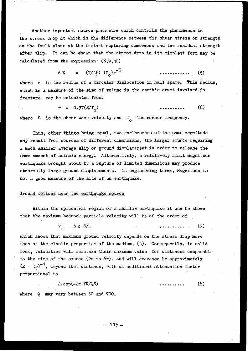
Another important source parametre which controls the phenomenon i s
the stress drop An which is the difference between the shear stress or strengt h
on the fault plane at the instant rupturing commences and the residual strengt h
after slip . It 6an be shown that the stress drop in its simplest form may b e
calculated from the expression : (8,9,10)
A Z
=
(7/16) (Mo )r-3 (5)
where r is the radius of a circular dislocation in half space . This radius ,
which is a measure of the size of volume in the earth's crust involved in
fracture, may be calculated from :
r = 0.37(5/fo ) (6)
where S is the shear wave velocity and fo the corner frequency .
Thus, other things being equal, two earthquakes of the same magnitud e
may result from sources of different dimensions, the larger source requiring
a much smaller average slip or ground displacement in order to release the
same amount of seismic energy . Alternatively, a relatively small magnitud e
earthquake brought about by a rupture of limited dimensions may produc e
abnormally large ground displacements . In engineering terms, Magnitude_i s
not a good measure of the size of an earthquake .
Ground motions near the earthquake sourc e
Within the epicentral region of a shallow earthquake it can be shown
that the maximum bedrock particle velocity will be of the order of
vm = A L S/µ . . . . . . . . . . (7 )
which shows that maximum ground velocity depends on the stress drop mor e
than on the elastic properties of the medium, (1) . Consequently, in solid
rock, velocities will maintain their maximum value for distances comparabl e
to the size of the source (2r to 6r), and will decrease by approximatel y
(R - 3r)-1 , beyond that distance, with an additional attenuation facto r
proportional to
2 .exp(-2n fR/QS )
where Q may vary between 60 and 700 .
(8). . . . . . . . . .
- 1 15 -
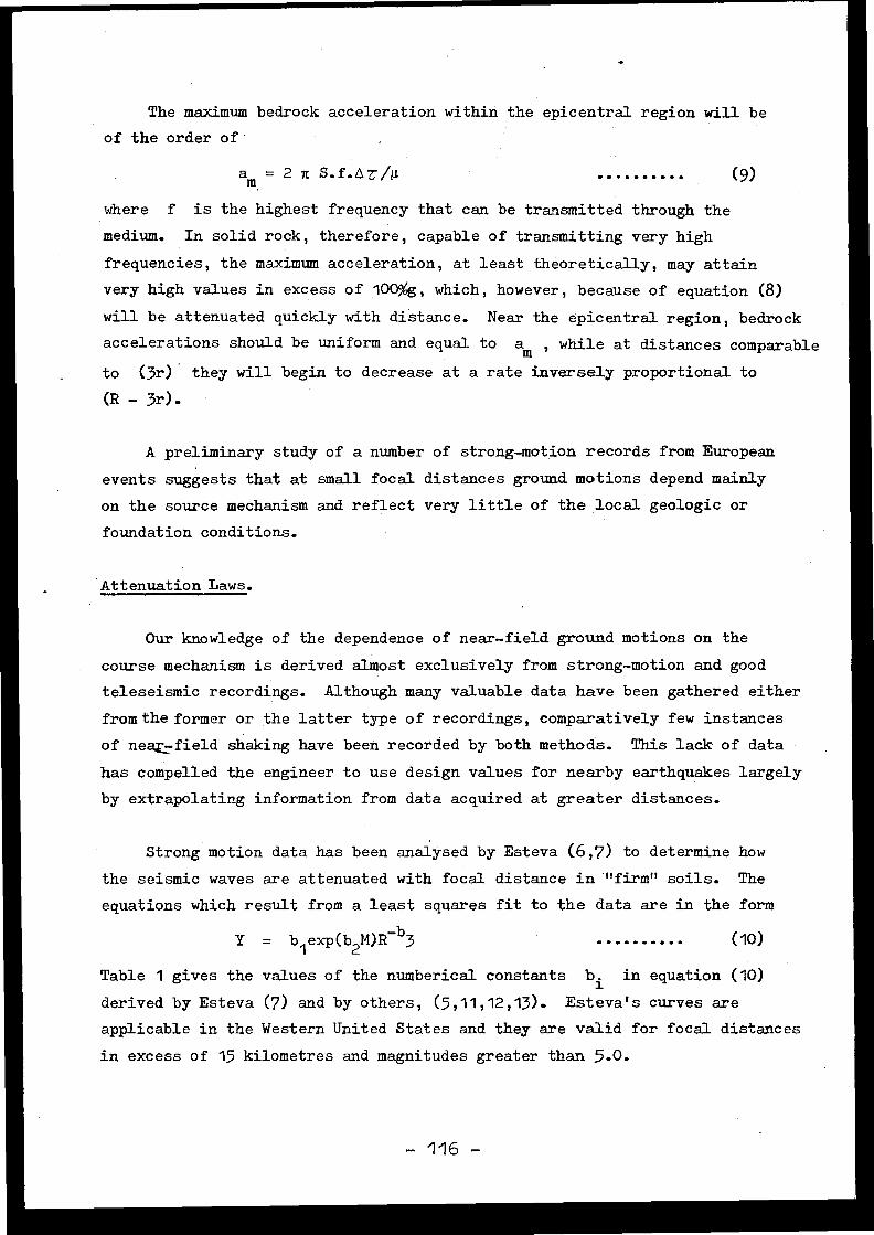
The maximum bedrock acceleration within the epicentral region will b e
of the order of
am = 2 n S .f.AV/µ
where f is the highest frequency that can be transmitted through th e
medium. In solid rock, therefore, capable of transmitting very hig h
frequencies, the maximum acceleration, at least theoretically, may attain
very high values in excess of 100%g, which, however, because of equation (8)
will be attenuated quickly with distance . Near the epicentral region, bedrock
accelerations should be uniform and equal to am , while at distances comparabl e
to (3r) they will begin to decrease at a rate inversely proportional t o
(R - 3r) .
A preliminary study of a number of strong-motion records from Europea n
events suggests that at small focal distances ground motions depend mainl y
on the source mechanism and reflect very little of the local geologic or
foundation conditions.
Attenuation Laws .
Our knowledge of the dependence of near-field ground motions on th e
course mechanism is derived almost exclusively from strong-motion and goo d
teleseismic recordings. Although many valuable data have been gathered eithe r
from the former or the latter type of recordings, comparatively few instance s
of neap field shaking have been recorded by both methods . This lack of dat a
has compelled the engineer to use design values for nearby earthquakes largel y
by extrapolating information from data acquired at greater distances .
Strong motion data has been analysed by Esteva (6,7) to determine ho w
the seismic waves are attenuated with focal distance in "firm" soils . The
equations which result from a least squares fit to the data are in the for m
Y = b l exp(b2M)R-b3
(10 )
Table 1 gives the values of the numberical constants bi in equation (10 )
derived by Esteva (7) and by others, (5,11,12,13) . Esteva's curves ar e
applicable in the Western United States and they are valid for focal distance s
in excess of 15 kilometres and magnitudes greater than 5 .0 .
(9)
- 116 -
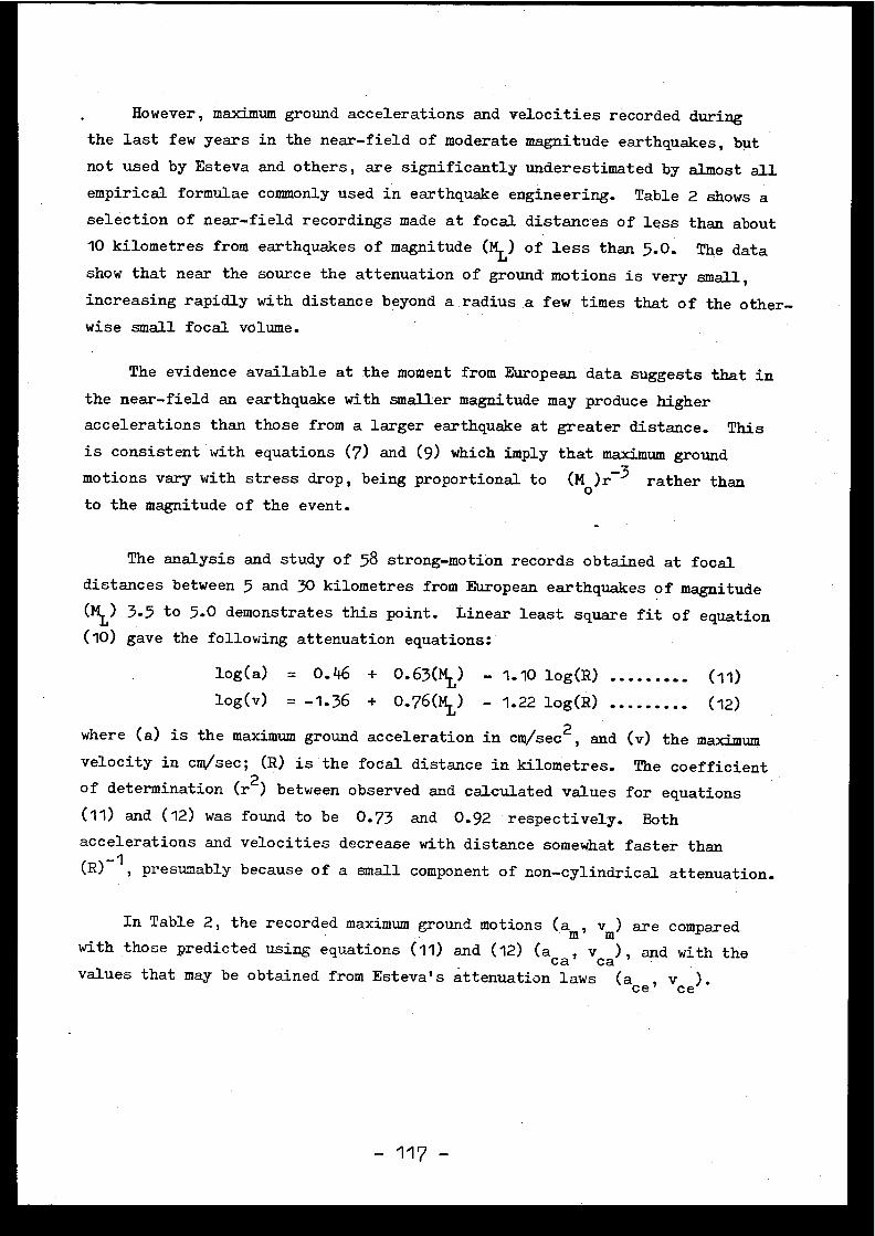
However, maximum ground accelerations and velocities recorded during
the last few years in the near-field of moderate magnitude earthquakes, bu t
not used by Esteva and others, are significantly underestimated by almost all
empirical formulae commonly used in earthquake engineering . Table 2 shows a
selection of near-field recordings made at focal distances of less than about
10 kilometres from earthquakes of magnitude ( ML) of less than 5 .0. The data
show that near the source the attenuation of ground motions is very small ,
increasing rapidly with distance beyond a radius a few times that of the other-
wise small focal volume .
The evidence available at the moment from European data suggests that i n
the near-field an earthquake with smaller magnitude may produce higher
accelerations than those from a larger earthquake at greater distance . This
is consistent with equations (7) and (9) which imply that maximum ground
motions vary with stress drop, being proportional to ( M0 )r 3 rather than
to the magnitude of the event .
The analysis and study of 58 strong-motion records obtained at focaldistances between 5 and 30 kilometres from European earthquakes of magnitude
(ML ) 3 .5 to 5 .0 demonstrates this point . Linear least square fit of equatio n
(10) gave the following attenuation equations:
log(a)
= 0 .46 +
0.63(ML) - 1 .10 log(R) (11 )
log(v)
= -1 .36 +
0.76(ML) - 1 .22 log(R) (12)
where (a) is the maximum ground acceleration in cm/se c2, and (v) the maximum
velocity in cm/sec ; (R) is the focal distance in kilometres. The coefficientof determination ( r2 ) between observed and calculated values for equation s
(11) and (12) was found to be 0 .73 and 0 .92 respectively. Both
accelerations and velocities decrease with distance somewhat faster than(R) -1 , presumably because of a small component of non-cylindrical attenuation .
In Table 2, the recorded maximum ground motions ( am , vm) are comparedwith those predicted using equations (11) and (12) (a
ca, vca), and with th e
values that may be obtained from Esteva's attenuation laws (aCe,vic e) .
Correlation of Intensity with ground motion s
So far the analysis of 150 strong-motion recordings obtained in Europ e
and in the Middle East suggest that there is a weak correlation with local
Intensities (MM) . For the range III+ < I VIII, the following empirical
relations have been obtained :
log(ah ) = 0 .10 + 0 .30(1
„î ) . . . . . . . . . . (13 )
log(av ) = 0 .37 + 0 .21(IMM ) . . . . . . . . . . (14 )
log(vh ) _ -1 .07 + 0 .30(IMM ) and . . . . . . . . . . (15 )
log(yv ) = -0 .49 + 0 .17(IMM ) (16)
where subscripts h and v designate horizontal and vertical components o f
motion. These equations differ little from those reported elsewhere (2) an d
the indication is that the scatter remains large, about 0 .7 of the mean. For
Intensities greater than V, both horizontal and vertical maximum acceleration s
on "hard ground" are larger by a factor of two than on "soft ground" . For peak
velocities this factor is somewhat smaller .
Design Spectra,
It is becoming increasingly common practice for the engineer to us e
response spectra for design purposes . Usually the designer is faced with
two alternative approaches . The first approach is to use an attenuation la w
such as Esteva's (7) together with the standard method proposed by Newmark
and others, (15,16,17), i .e . to use the Standard Design Spectra, or alter -
natively to depart from this procedure provided that adequate justification
if given for this .
Departure from the first approach is fully justified in the case o f
design in the near-field of a medium magnitude earthquake . This situation
is encountered in all regions of high, medium or even low seismicity where a
magnitude ML = 4.0 earthquake at a focal distance of, say, 5 to 10 kilometre s
from a site/ which may be either the background seismicity or the extrem e
design condition . As recent near-field strong-motion recordings in Europ e
clearly indicate, nearby, relatively low-magnitude earthquakes can generat e
maximum ground accelerations and velocities comparable to those from large r
events at greater distances, and such events have not been used in the firs t
approach .
- 118 -
Figure 2 shows the actual spectra (2% damped) of some of the events
analysed. These plots show peak response occurring at frequencies betwee n
5 and 9 Hz with an amplification factor for velocity of about 3 .5 . The values
of this factor fall off more rapidly towards the lower frequencies and for al l
practical purposes at about 3 Hz the spectral response does not exceed th e
ground acceleration .
The use of the first approach, therefore, may lead to unrealistic result s
for near-field events . The following example illustrates this point . Consider
that the 2% damped response spectrum is required for a site located 6 kilometres
from a magnitude 4.7 earthquake (Table 2, case 9/26RN) . Esteva's laws predict
maximum ground accelerations of 11 .4%g and velocities of 10 .3 cm/sec . The
corresponding ground spectra are shown in Figure 3 (curve ES) . Using Newmark' s
technique we may construct the response spectra (curve EN) . The differenc e
between predicted (EN) ' and actual response (RA) is significant, the former
being on the unsafe side for short period structures .
In contrast if we use equations (10) and (11) to predict ground motions ,
their ground and response spectra (AM and AN) compare reasonably well wit h
the actual response spectra (RA) at high frequencies but otherwise belo w
4 Hz the response is grossly overestimated .
Returning to Figure 2, we notice that response values at frequencie s
larger than 5 Hz exceed 100%g, while ground acceleration exceeded 50%g . Yet ,
the damage associated with these motions was disproportionaly small . The
question here is whether these peak accelerations and their correspondin g
response values are at all realistic and whether structural design can b e
carried out using response spectra of this kind . Dynamic loading leading
to yielding and failure of an engineering structure is a strongly non-linear
process and its effect on différent types of structures and building materials
can only be assessed in the time domain . The use of peak ground accelerations
and response spectra may be accepted for situations in which dynamic loadin g
is well below the yield capacity of structures . However, in the near-fiel d
of an earthquake design in the frequency domain may lead to unrealistic an d
even perhaps over-conservative results .
The spectral curves in Figure 2 or 3 are representative of the respons e
of an ideally elastic slightly damped oscillator with zero interference or
- 119 -
interaction with its foundation . This is a rather unrealistic model . In
reality structural interaction alone is likely to eliminate some of the high
frequency accelerations . The simplest possible, almost crude, example woul d
be that of a rigid foundation slab acted upon by a series of acceleratio n
pulses travelling along its length with frequency (f) . During an earthquak e
the distribution and magnitude of induced absolute horizontal and vertical
accelerations on the rigid foundation slab of linear dimensions (L) wil l
change rapidly with time, passing from one configuration into another an d
persisting with their maximum value at a point for extremely short durations .
If it be assumed that during the passage of the disturbance there will be n o
separation or slip between the rigid slab and the ground, the average maximum
acceleration to act on the slab at an instant will be always equal to o r
smaller than the maximum free-field ground acceleration ag
af. The ratio
of the slab to the free-field acceleration q = a/a f will depend on th e
spatial distribution of ground accelerations along the length (L) of the slab .
The simplest possible case would be for a sinusoidal wave of frequency (f )
travelling with velocity (S) . Figure 4 shows the variation of (q) with
k = S/Lf. From this figure we notice that for a rigid structure, say, 10 0
metres long founded on soft bedrock with S = 800 m/sec ., the effect of the
rigid slab on frequencies, say, of 5 Hz would be to reduce the free-fiel d
acceleration by 53% (q = 0 .47) ; accelerations travelling with frequencies o f
10 Hz will be reduced by 82%. This effect may acoDunt not only for th e
relatively small damage caused to large structures in localities wher e
high frequency free-field accelerations exceeded 30 to 40%g, but als o
for the comparatively small accelerations measured in a few larg e
structures in the near field of some recent earthquakes .
Figures 5 to 7 show the filtering effect of a rigid foundation sla b
on the high-frequency content of a response spectrum produced by a rea l
earthquake motion. In these figures T is the undamped natural period of
oscillators fixed on a rigid slab of linear dimensions L , resting on a n
elastic foundation material of shear-wave velocity S ; (Ts = L/S) . The
contours shown on these figures are lines of equal Sa/am , where Sa is the
acceleration response value that corresponds to a particular pair T and Ts ,
for 5% damping, and am is the maximum free-field acceleration . In other
120 -
words, figures 5 to 7 show the "amplification response envelope" of a
particular free-field ground motion as a function of the dimensions of th e
slab and resilience of the foundation material . For Ts = constant, the
amplification response envelope reduces to the acceleration respons e
spectrum of a slab with L/S = constant, while for Ts = 0 it reduces to the
free-field acceleration response spectrum .
In applying this analysis to actual strong-motions, for instance t o
one of the Ancona recordings (14 June 1972, ML = 4.2 ; am = 42%s,Figure 5) ,
to the Parkfield-2 record (Figure 6) and to the well-known Paciome recor d
(Figure 7), we find that the larger the dimensions of the slab or the softer
the foundation materials are, the more high-frequency response will b e
reduced, for many practical cases well below the maximum free-fiel d
acceleration .
Although there are many questionable assumptions in this simpl e
engineering approach, field observations and strong-motion records indicat e
that both maximum ground accelerations and their response spectra are fa r
from being a good measure of the damaging potential of an earthquake .
Conclusions
Basing our evidence on strong-motion records obtained in Europe an d
in the Near East during the last few years, and also on field evidence from
recent earthquakes, we may conclude with the following remarks :
- In assessing earthquake risk the relocation of foci of pre-1960
events is absolutely essential . Such a relocation should be based on a
JED-type technique in which macroseismic data should be used to reduce bias .
- Earthquake magnitude is a poor measure of the size of a "desig n
earthquake" . Instead, attempts should be made to assess more meaningfull y
- 121 -
earthquake characteristics, such as seismic moment and focal mechanism .
Existing attenuation laws are inadequate to predict peak groun d
motions near the source of a medium-magnitude earthquake (M L
5 .0) . For
the conditions described in this paper we propose the use of equation s
(11) and (12) .
- The correlation of Intensity (MM) with peak ground motions as
described by equations (13) through (16) is very weak, and the use of thes e
equations is not recommended for design purposes ; they are of an index natur e
and they should only be considered in conjunction with the risk implicit i n
their use .
- Current design practice does not consider the loss of energy at
high frequencies due to wave-length and foundation interference . This ,
together with radiation are important considerations which finite-elemen t
methods cannot cope with .
- Neither maximum accelerations nor standard response spectra ar e
meaningful tools for the design of important engineering structures in the
near-field of an earthquake of any magnitude . Instead, we propose the use
of a suitable number of real time-histories of strong-motion record s
obtained from events with source parameters similar to those of the design '
earthquake . The use of artificial time-histories will be as good as the
assumptions made for their construction .
- At the present stage of knowledge the use of strong-motion dat a
for conditions different from those in which they were recorded is no t
recommended. The adoption of a transfer model with which ground motion s
can be transferred from the surface to bedrock and to another site is no t
always likely to be effective since whatever model might be used some dat a
would be found to agree with it .
- A very rapid increase in the strong-motion instrumentation in a
country without an equally rapid development of its seismic network i s
- 122 -
likely to be a very ineffectual and unreasonably expensive way of improvin g
our knowledge about strong ground motions .
Acknowledgement s
This report presents briefly part of the results obtained so far b y
the ECEE Working Group on Strong-Motion Studies . The author is indebte d
to Prof . F . Peronaci for his generous help in the study of both strong
motion and teleseismic recordings of the Ancona sequence . Thanks are also
due for generous assistance to Dr . E. Iansiti of CNEN, Mr. A. Moinfar o f
PBO Tehran, Prof . G. Grandori, Prof . M. Caputo of the ING Rome, Dr . V.
Mikhailov of the IZIIS Skopje, and Dr . A . Roussopoulos of the NTUA Athens .
Also, I would like to thank Dr . T. Giizey of Deprem .Arast . Ankara and Dr .
F. Borges of Lisbon.
The author wishes to acknowledge helpful discussions with Mr . K. McCue ,
Dr . S .K. Sarma and Mr . M . Etemadi-Idgaahi of Imperial College .
This research is supported by the Science Research Council, London, an d
in part by NERC London .

REFERENCES
1 . AMBRASEYS N . (1969) "Maximum intensity of ground movement scaused by earthquakes "Proc .4th World Conf.Earthq.Eng., vol.1, p .A-2-154.
2 . AMBRASEYS N . (1974) "The correlation of Intensity with groundmotions"Proc .l4th Assembly European Seism . Commission, Trieste .
3. BRUNE J. (1970) "Tectonic stress and the spectra of seismi cshear waves for earthquakes"Journ .Geoph.Research, vol.75, p.4997, vo .76, p.5002 .
4 . CORNELL A . (1968) "Engineering seismic risk analysis "Bull .Seism.Soc .America, voo .58, p .1583 ; also 4th WorldConf .Earthq.Engineering, vol . 2, paper A-1/69, 1969 .
5 . DONOVAN N. (1972) "Earthquake hazards for buildings "Build.Sci.Series no .46, Building-Practice for DisasterMitigation, Boulder, Colorado .
6 . ESTEVA L . (1970) in : Seismic Design for Nuclear Power Plants ,ed. R.J. Hanson, M.I.T. Press .
7 - ESTEVA L . (1974) "Geology and predictability in the assessmentof seismic risk"Proc .2nd Int .Conf.Assoc .Eng.Geologists, Sao Paulo .
HASKELL N. (1964) "Radiation of surface waves from point sourcesin multi-layered media"Bull .Seism.Soc .America, vol .54, p .377.
HASKELL N . (1964) "Total energy and spectral density of elasti cwave radiation from propagating faults"Bull.Seism .Soc .America, vol .54, p.1811 .
10 . J r±EYS H. (1931) "On the cause of oscillatory motion inseismograms"Royal Astr .Soc . Monthly Notes, Geoph .Suppl . no .2, p .407 .
11 . KANAI K., KIRANO K., ASADA T . (1967-68) "Strong earthquake motio nrecords in Matsushiro earthquake swarm area "Earthq.Research Inst .Publ-.Part 1& 2, Univ . Tokyo.Also, Bulletin Earthq .Research Inst ., vols. 44 and 45.
12 . MICKEY W.V. (1971 )
_"Strong motion response spectra"Earthquake Notes, vol .42, n .1, p.5.
13. MILNE W., DAVENPORT A . (1969) "Distribution of earthquake risk inCanada"Bull .Seism.Soc .America, vol .59, p.754.
- 124- -
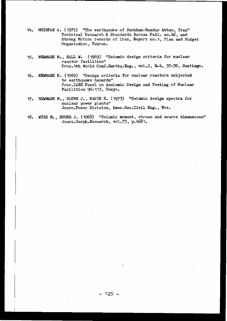
14. MOINFAR A . (1975) "The earthquake of Sarkhun-Bandar Abbas, Iran "Technical Research & Standards Bureau Publ . no.46, andStrong Motion records of Iran, Report no .1, Plan and BudgetOrganision, Tehran .
15 . NEWMARK N., HALL W . (1969) "Seismic design criteria for nuclearreactor facilities"Proc .4th World Conf .Earthq.Eng ., vol.2, B-4, 37-50, Santiago .
16 . NEWMARK N. (1969) "Design criteria for nuclear reactors subjectedto earthquake hazards"Proc .IAEE Panel on Aseismic Design and Testing of Nuclea rFacilities 90-113, Tokyo .
17 . NEWMARK N.,BLUME J., KAPUR K. (1973) "Seismic design spectra fornuclear power plants"Journ .Power Division, Amer.Soc .Civil Eng ., Nov.
18 . WYSS M., BRUNE J. (1968) "Seismic moment, stress and source dimensions "Journ.Geoph.Research, vol.73, p .4681 .
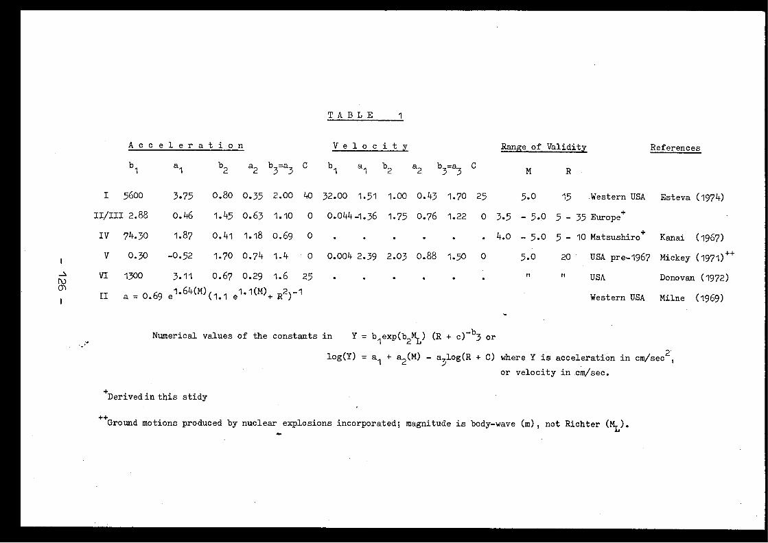
TABLE
1
A c c e l e r a t i o n V e l o c i t y Range of Validity References
b 1 a 1
b2 a2
b3=a3 C b 1
a 1 b2 a2 b3=a3
C M R
I 5600 3 .75
0 .80 0.35 2 .00 40 32.00
1 .51 1 .00 0.43 1 .70 25 5.0 15
Western USA Esteva (1974)
II/III 2 .88 0 .46
1 .45 0.63 1 .10 0 0.044-4.36 1 .75 0.76 1 .22 0 3 .5 - 5 .0 5 - 35 Europe +
IV 74.30 1 .87
0 .41 1 .18 0 .69 0 . . 4.0 - 5 .0 5 - 10 Matsushiro+ Kanai
(1967 )
V 0 .30 -0 .52
1 .70 0.74 1 .4 0 0 .004 2.39 2 .03 0 .88 1 .50 0 5 .0 20
USA pre-1967 Mickey (1971 ) ++
VI 1300 3 .11
0.67 0 .29 1 .6 25 It it USA Donovan (1972 )
II a = 0 .69 e164(M)
(1 . 1 e 1 .1(M) + R2 ) 1Western USA Milne
(1969)
Numerical values of the constants in
Y = blexp(b2ML) (R + c) -b3 or
log(Y) = a1 + a2 (M) - a31og(R + C) where Y is acceleration in cm/sec2 ,
or velocity in cm/sec .
+Derived in this stidy
++Ground motions produced by nuclear explosions incorporated ; magnitude is body-wave (m), not Richter ( ML) .
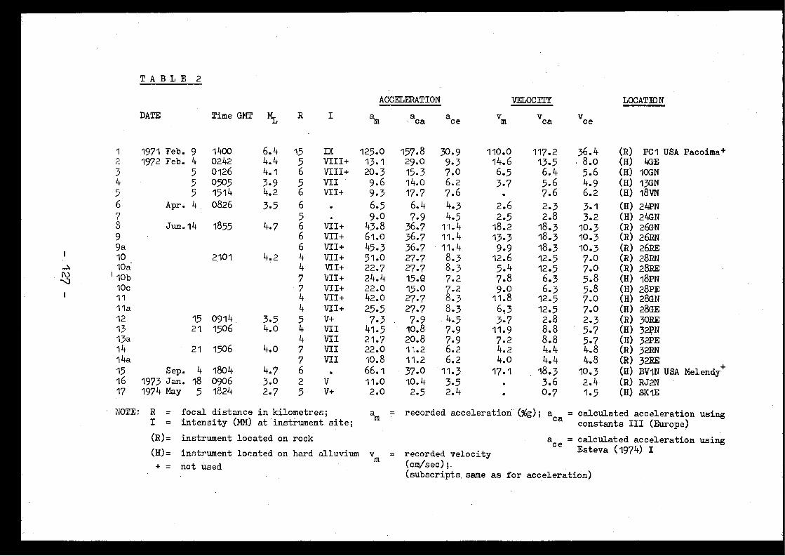
(H)= instrument located on hard alluvium
TABLE
2
1
DATE
1971 Feb . 9
Time GMT
1400
ML
6 .4
R
15
I
IX2 1972 Feb. 4 0242 4.4 5 VIII+3 5 0126 4.1 6 VIII+4 5 0505 3 .9 5 VII5 5 1514 4.2 6 vil+6 Apr . 4 0826 3.5 67 58 Jun.14 1855 4.7 6 vil+9 6 vii+9a 6 Vil+
10 2101 4.2 4 VII+10a 4 VII+10b 7 VII+10c 7 VII+11 4 VII+11a 4 VII+12 15 0914 3.5 5 V+13 21 1506 4.0 4 VII13a 4 VII14 21 1506 4.0 7 VII14a 7 VII15 Sep .
4 1804 4.7 616 1973 Jan. 18 0906 3.0 2 V17 1974 May
5 1824 2 .7 5 V+
ACCELERATION
ace
VELOCITY
vice
LOCATIO N
am aca m
vca
125.0 157.8 30 .9 110 .0 117 .2 36 .4 (R) PCI USA Pacoima+13.1 29.0 9.3 14.6 13.5
. 8 .0 (H) 4GE20.3 15.3 7.0 6.5 6.4 5 .6 (H) IOGN9.6 14.0 6.2 3.7 5.6 4.9 (H) I3GN9.3 17.7 7 .6 7 .6 6 .2 (H) 18VN6.5 6 .4 4.3 2.6 2.3 3.1 (H) 24PN9.0 7 .9 4.5 2.5 2 .8 3.2 (H) 24GN
43 .8 36 .7 11 .4 18.2 18.3 10.3 (R) 26GN61.0 36 .7 11 .4 13.3 18.3 10.3 (R) 26RN45.3 36 .7 11 .4 9 .9 18 .3 10.3 (R) 26RE51.0 27 .7 8 .3 12.6 12.5 7.0 (R) 28RN22.7 27 .7 8 .3 5.4 12 .5 7.0 (R) 28RE24.4 15 .0 7 .2 7 .8 6.3 5.8 (H) I8PN22.0 15 .0 7 .2 9.0 6 .3 5.8 (H) 28PE42.0 27 .7 8 .3 11 .8 12 .5 7.0 (H) 28GN25.5 27 .7 8 .3 6.3 12 .5 7.o (H) 28GE7.3 7 .9 4.5 3.7 2 .8 2.3 (R) 30RE
41.5 10 .8 7 .9 11 .9 8 .8 5.7 (H) 32PN2.1 .7 20 .8 7 .9 7.2 8 .8 5.7 (H) 32PE22.0 11 .2 6 .2 4.2 4.4 4.8 (R) 32RN10.8 11 .2 6 .2 4.0 4.4 4.8 (R) 32HE66.1 37.0 11 .3 17.1 18.3 10.3 (H) BV1N USA Melendy +11 .o 10 .4 3 .5 3.6 2.4 (R) RJ2N2.0 2 .5 2 .4 0.7 1 .5 (H) SKIE
+ = not used
NOTE: R = focal distance in kilometres ;
a = recorded acceleration (%g) ; aca calculated acceleration usingI = intensity (MM) at instrument site ;
m
ca constants III (Europe )
(R)= instrument located on rock
aCe = calculated acceleration using
recorded velocity
Esteva (1974) I(cm/sec) ; .(subscripts same as for acceleration )
v =m
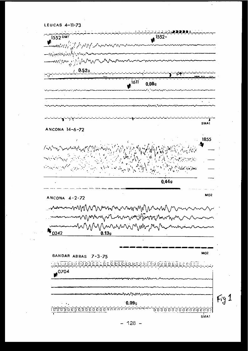
L E U CAS 4-11-73
,,. .
.
-.1552 GMT
1552 ÷
0.529
161 1*
0.08g
SMA 1
ANCONA 14-6-72
. 1855
er',r .',\ t .
v'
.
'r )'\
,,
I ?
;,t .1 ) é '
i .
'Y'PnI
',i ,
tru
•
J
,,. . . .
‘,
,
,'',,,,r,
,,.
IA,
.
'.,.•A . ..\h'i- ''-,
0.44g
f' • A
---w,Ah'',rf,jAv
4, ^ i ,-.--..-.0.,W ,Vya
"au", um. ult., mulct
ANCONA 4-2-72
M0 2
..............
BANDAR ABBAS 7-3-75
-128 -
M02
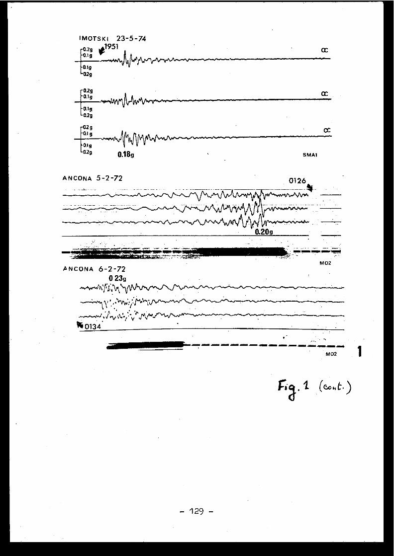
IMOTSKI 23-5-74o2g *1951O.l g
Ql g02g
CC
-02 g-0.1 g
-O.l g-02g
-0.2 g-ai g
O.I g0.2g 0.18g
ANCONA 6-2-720 23g
% 0134
..................
S MAt
1M02
(Cotit . )
-129 -
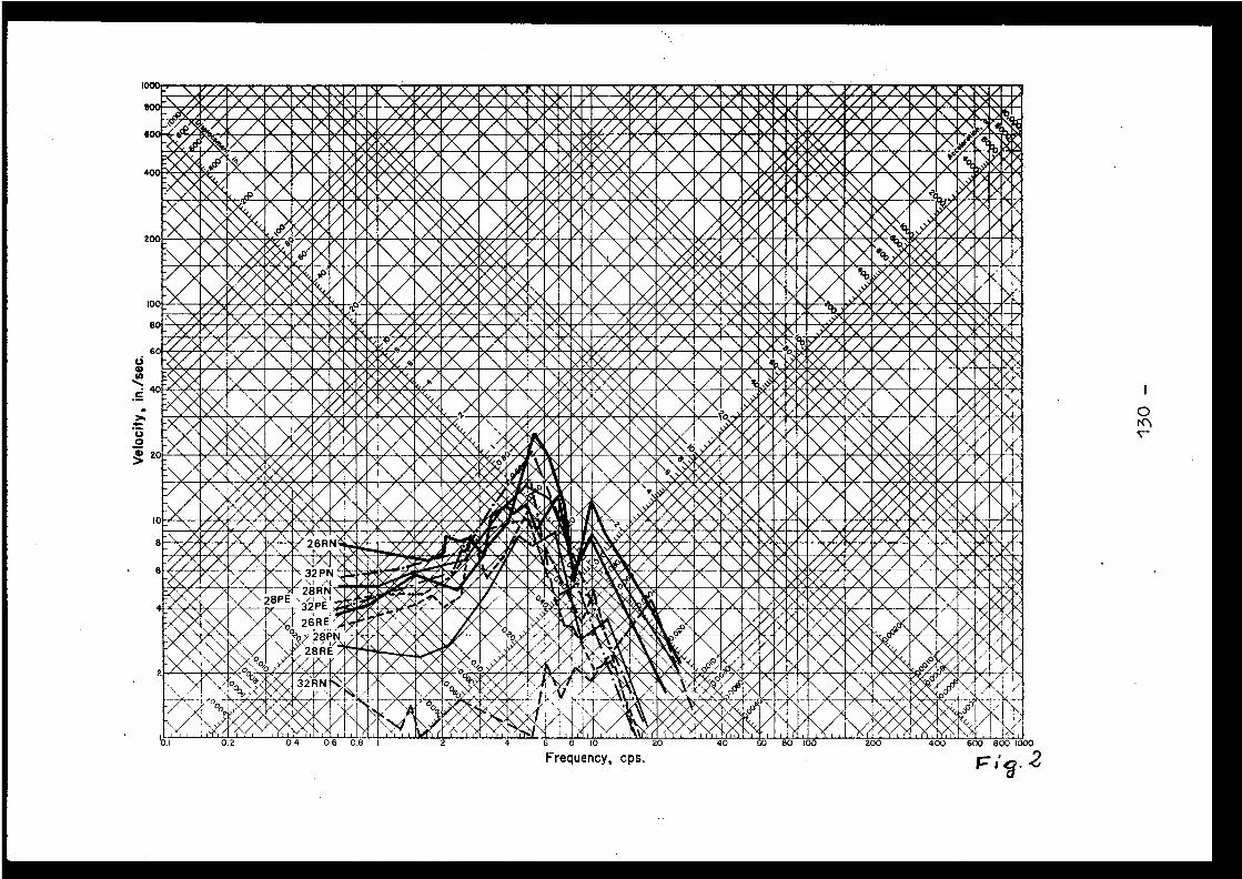
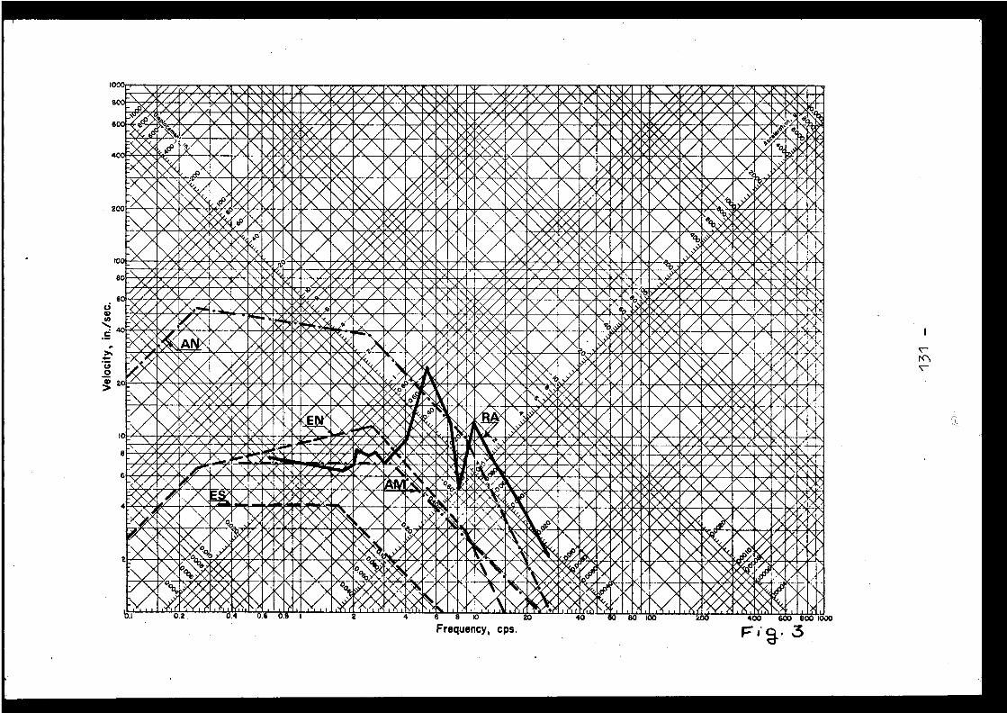
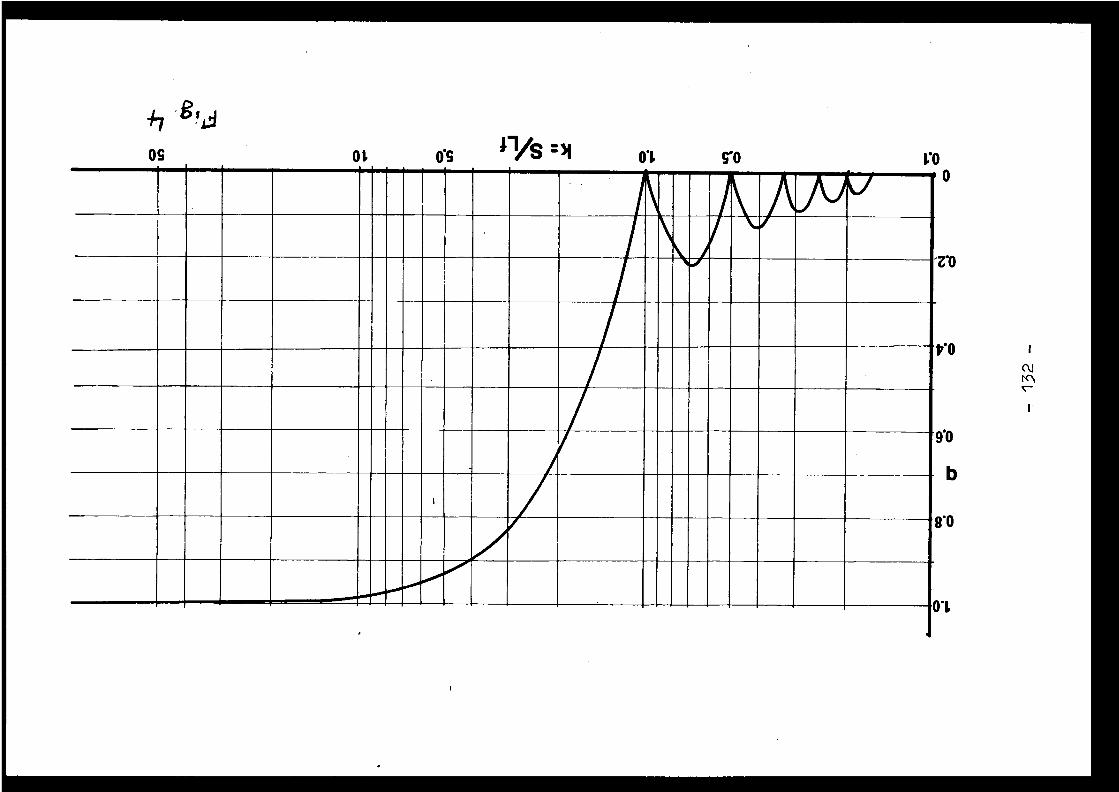
0L 0'1 5'0
0'L
-z.0
8'0
9'0
b
P.O
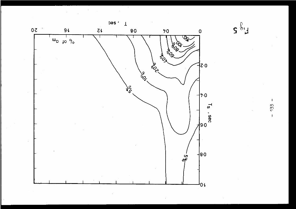
0•Z Zi, 9 .0 7.0 0
zas '
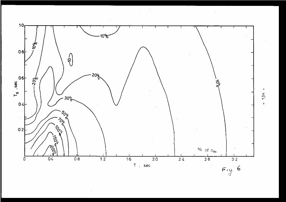
1
I
I
I
0
I
~
I
I
Ir
1 0
0 . 8
0 . 6
U)
U)f-
0 .4
0 .2
0 . 4
0 . 8
1 . 2
1 . 6
2 . 0
2 . 4
2 . 8
3 . 2T , sec
of a m
0 . 2
0 .4
0 . 6
0S
1 . 0
t2
t4
1 . 6
1 .8
2. 0T , sec 7
Typical earthquake record : an earthquake in southern Greece (origin time 03 1254.2GMT on April 5,1965, ep'centre at 37 . 7°N,21 .8°E), recorded by a long-period verticalseismogra; L at Uppsala . Time increases from top to bottom (there is one hour betwee neach line) and from left to right (one minute between each mark) . The main phasesare P (longitudinal wave), S (t a.'sverse or shear wave), and R (surface Rayleighwaves) . The maximum amplitudes (in the R gro.:,) correspond to a ground displace-ment of 0. 13mm . The background noise (microseisms) is clearly seen on the traces
above and 'Ialow the earthquake record.
- 136 -

General Discussion
Discussion générale
D. COSTES, Franc e
Il y a deux sortes de cartes sismiques : les cartesexplicatives préparées par les géologues et sismologues, fai-sant intervenir tous les éléments sismotectoniques, et les cartesen probabilités, utiles à l'ingénieur . Il semble que les car-tes en probabilités d'action sismique constituent l'interfacenormale entré le sismologue et l'ingénieur, sous réserve qu eles données en probabilités ainsi fournies soient suffisantes .
C .G . DUFF, Canad a
In Canada (especially for eastern Canada where ou rnuclear power plants are located) we are in the process ofdeveloping a new seismic map based on the equal recurrence rate -area probability method, similar to what was described in pa -per 2 .1 this afternoon .
P.GIULIANI, Italy
In Italy, there are seismic maps, based upon proba -bilistic evaluation of earthquake occurrence . But I believethat in site analysis for nuclear power plants their usefulnes sis limited only to a very general examination of the site re -gion ; for the point site an ad hoc seismic analysis shouldbe performed in any case .
M . BORK, F .R . of Germany
For the purpose of assessing the seismic risk t onuclear power plant sites in Germany a generalized map o fearthquake zones has been developed, which serves as an ini -tial guideline for the determination of the Design Earthquake .These earthquake zones are developed without considering th elocal geological conditions and foundation properties of aspecific site . More detailed seismic maps are in the develop -ment . Some more information on the generalized earthquake mapis given in paper 6 .2 of this meeting .
E. GLAUSER, Switzerland
On the basis of the very extensive seismic ris kanalysis work conducted for thé Swiss nuclear power plants ,work has started on the preparation of seismic risk maps cover-ing the whole of Switzerland . This work was initiated by th eSwiss Agency for the Safety of Nuclear Power Plants and i scarried out in a joint venture by the Swiss Institute o f
- 137 -

Geophysics and the consulting firm of Basler and Hofmann inZürich .
The work makes use of the methodology developed byC .A . Cornell and H .A. Merz for the establishment of seismi cintensity maps for different presupposed probabilities o foccurrence .
The project is scheduled for termination by the en dof 1976 .
J.MEZCUA, Spain
As a seismologist I know what I mean by "Seismotec -tonic Province" but I don't see that province as small as i twas presented here . I think this point is very critical inany risk analysis .
J .P .ROTHE, France
En Espagne ; les provinces sismotectoniques son tprobablement mieux def finies et plus étendues qu'en France ; oùil existe une juxtaposition très fine de différentes unite sgéologiques .
N .N . AMBRASEYS, United Kingdom
Are, the seismic maps you just referred to, base don recalculated data or on old epicentral determinations ?Do you know anything about the focal mechanisms of thes eevents ? What is the value of seismic maps based on old deter-minations ?
J .P . ROTHE, Franc e
Dans l'exemple qui a été donné de la feuill eMarseille à 1 :250 .000 les épicentres ont été révisés en fonc-tion des données macrosismiques détaillées et éventuellementdes données microsismiques . Il n'a pas été tenu compte de sépicentres calculés par l'ISS .pour la période 1900-1950 .
Il n'a pas été fait de calculs de mécanismes aufoyer faute de données assez nombreuses .
D . COSTES, Franc e
On recommande en général l'étude de deux niveauxappelés par exemple SI et S2 . :
- SI rapporté à la possibilité de continuer l'exploi-tation sans examen spécial des détériorations . La
- 138 -
probabilité serait de l'ordre de 10-2/an .
- S2 rapporté à la possibilité d'assurer seulement l asûrete des populations vis-à-vis de la dispersio ndes produits dangereux .
Le niveau SI est considéré au sens de la sûreté, pou rla raison qu'à ce niveau on n'aurait pas à effectuer une véri -fication de l'état de l'installation avant de donner l'autori -sation de continuer le fonctionnement . Ceci nous paraît bienpeu important, lorsque la probabilité d'atteindre SI est trèsfaible, ce qui est le cas en France . On devrait pouvoir s'af -franchir d'un tel examen au titre de la sûreté, sauf demand eexpresse de l'exploitant .
En revanche, l'analyse des situations avec dégrada-tion partielle, permettant l'examen global de la sûreté su rune plage étendue de niveaux d'agression, pourrait requérirl'examen d'au moins deux niveaux typiques à risque non négli -geable de rupture .
On pourrait par exemple recommander l'examen d ucomportement aux agressions ayant les niveaux de probabilit é10-5 et 10-5 par an, ou encore 10-4 et 10-6 .
J . DESPEYROUX, France
Je voudrais signaler qu'un certain nombre d'asso-ciations internationales (Association Internationale des Pont set Charpentes, Comité Européen du Béton, Convention Européenn ede la Construction Métallique, Fédération Internationale d ela Précontrainte) ont mis sur pied un Comité Mixte charg éd'étudier les problèmes de sécurité structurale .
Les travaux de ce Comité sont basés sur une approch eprobabiliste . Pour les séismes, le Comité a donc essayé dedégager les données d'une telle approche dans le cas des séis -mes et propose d'adopter pour leur distribution une lo i"Extrême type II", c'est-à-dire une loi du type :
F(x) = exp L-(kx) 7portant sur les accélérations maximales au sol . La valeur 0a été choisie égale à 3 . Avec cette valeur, le coefficient d evariation ressort à 0,7 et la valeur caractéristique a 95 % ;c'est-à-dire celle qui n'a que 5 % de chances d'être dépasseependant la période de référence, à environ deux fois la va-leur moyenne .
Si par ailleurs on se reporte à la proposition de
s'
M. Shukla de prendre comme OBE le séisme dont la période d eretour est 50 ans et de prendre comme SSE celui ayant une accé -lération au sol double de celle de l'OBE, l'application d ecette loi conduit à considérer que le SSE devrait être celu idont la période de retour est de 400 ans .
- 139 -
Malgré les difficultés de principe et de fait qui s'attachentà l'étude des distributions de phénomènes extrêmes, il serai tsouhaitable que les sismologues puissent renseigner les cons -tructeurs sur la validité des lois proposées .
E . ROBERT, Franc e
M . Despeyroux, en disant que le Comité européen d eliaison des constructeurs traite aussi comme une catégori espéciale les séismes extrêmes, a fait état de l ' applicationd'une loi de valeurs extrêmes considérée, si j'ai bien compris ,comme spécifique de ces phénomènes .
Je voudrais sur ce point faire deux remarques :
1. Rappeler le fait que la fréquence n'étant pas l aprobabilité celle-ci, à un risque d'erreur accepté, ne peutêtre exprimee que par une "fourchette" .
Si far exemple, un phénomène naturel a été en nannées observe seulement une fois (une intensité déterminé eatteinte ou dépassée) à la fréquence et au risque d'erreurde 5 %, la formule de Poisson permet nd'associer une probabi-lité comprise entre 3x 1o-2 et 5,5 . Dans ces conditions, une
n
nloi de valeurs extrêmes telle que celle signalée par.M . Despeyroux ne résout pas le problème de l'incertitude fon -damentale qui est dans la nature des choses et ne permet pa sde préciser la probabilité des phénomènes peu observés .
2. Citer une étude de M . Bessemoulin, directeur généra lde la météorologie nationale, relative à la Loi de Gumbel . Ilmontre avec quelles réserves il convient de recourir à d etelles lois, auxquelles il ne reconnaît d'autre intérêt pra -tique qu'une extrapolation limitée et dans la mesure où lesvaleurs observées veulent bien s'aligner sur une droite d eGumbel .
Il importe donc d'être bien conscient de l'impréci-sion et des marges d'incertitudes importantes qui caractéri-sent cette approche .
H . SHIBATA, Japan
There is a possibility that the upper bounded valueof magnitude exists deterministically . It might depend onlocal geology and tectonic structure, because possible magni-tude is a function of volume of related rock and its strength .In Japan we are trying to figure out these figures of themaximum magnitude on the map .

J .P . ROTHE, Franc e
Les sismologues peuvent fournir des valeurs maximale sde magnitude, en relation avec les diverses provinces sismotec-toniques .
D . COSTES, Franc e
Les ingénieurs croient en général difficilement àdes maxima absolus des phénomènes naturels ; mais sur le planpratique, une décroissance rapide de probabilité au delà d'unseuil donne un effet équivalent .
Je voudrais revenir à la question des intervalles d econfiance des données en probabilite sur les séismes . Ces in-tervalles seront toujours très larges et difficiles à précise ren raison du petit nombre de données, mais les valeurs moyenne sreprésentent cependant la meilleure information possible, cell equi doit guider les décisions sauf objection logique .
J .L . ZEMAN, Austri a
I should like to ask a question from the famou sgeodynamicists among us : Is it really possible to determinefor a given site an upper bound for the intensity or magnitud eof earthquakes ? If this is possible, it would be the prope rmeasure to base the SSE on ; the OBE could still be determinedby a probabilistic approach .
J .P . ROTHE, Franc e
Oui, les sismologues peuvent fournir des valeur smaximales de magnitude, en relation avec les diverses provin-ces sismotectoniques .
N .N. AMBRASEYS, United Kingdom
If seismologists could agree on precise data, thi swould give the necessary guarantees to engineers ; but we didnot reached that stage yet .
A.BARBREAU, Franc e
Le but des cartes sismotectoniques est justement d erassembler l'ensemble des données tectoniques et historique spermettant d'arriver à des évaluations telles que la magnitud emaximale dans une région donnée .

Session 3 - Soil-Foundation Interaction
Séance 3 - Interaction Sol-fondatio n
Chairman - Président
H . SHIBATA
Summary of Session 3
D .Costes began by summarising classical methods fo ranalysing ground-foundation interaction on the basis of a pa -per by U. Holzlohner given at Pisa in 1972 .
J .R . Hall (Paper 3 .1) gave a comparison of the finit eelement and lumped parameter methods for foundations calcula -tions . He discussed how to determine inter-block relationship sfor a buried two-dimensional foundation subjected to a horizon -tal shear stress . The lumped-masses method gave results veryclose to those obtained using the more costly finite elementmethod, and was the only one which enabled the safety coeffi -cients to be expressed in terms of damping by energy diffusion ,which could be both substantial and very safe . The author als odescribed techniques for measuring soil properties, by drillingand by tests on local specimens .
J .P . Wolf (Paper 3 .2) used a direct, three-dimensiona ldynamic calculation to study the motion of a mat capable of lif -ting off and slipping, subjected to a time-dependent horizonta land vertical wave propagating horizontally. The number of de -grees of freedom was reduced at the outset by a modal analysis .
K . Fullard (Paper 3 .3) indicated that the CentralElectricity Generating Board was now tending to use lumpedmethods and time-history calculations in project designs . Thedifficult problems of the soil-foundation interaction and th eeffects of soil stratifications and wave propagation would b eanalysed progressively .
J .F.Vernet (Paper 3 .4) examined all kinds of wave sthat could arise in an earthquake, particularly the plasticwaves at the focus .
C . Plichon (Paper 3 .5) described a general anti-seismic mat bearing system comprising supports consisting o fa stack of enclosed neoprene plates and frictions pad t oeliminate peak stresses . Energy was thus concentrated in th efirst, highly deformable mode and all stresses considerablyreduced . Power stations could be standardized, with only th esupport structure being adapted to each site .
The following items were the subject of particularcomment :
- Knowledge of the stratification and dynamic charac -teristics of the ground was of great importance ,even though damping by energy diffusion was fairl yeasy to evaluate and generally predominated .
- 144-

- strength limits related to repeated stresses (lique -faction) required representative experiments whic hwere very difficult to carry out, together with areal understanding of the phenomena involved .
- The calculations could take account of comple xeffects, particularly the filtering out of hig hfrequencies by massive foundations, and in certai ncases had succeeded in correlating the actual move -ments measured ; however the theoretical descriptio nof seismic waves was generally lagging behind th edevelopment of calculational tools .
- It seemed likely that not enough consideration wasbeing given to amplitude limitations in depth, asobserved for example at the Humboldt Bay plant .
- The antiseismic support system described was th eonly one mentioned at the meeting ; this was regret -table in view of the value of such systems .

Résumé de la Séance 3
D . Costes résume tout d'abord, d'après une communi-cation de U. Holzlohner à Pise en 1972, des méthodes classique sd'analyse d'interaction sol-fondation .
J .R . Hall (Communication 3 .1) compare, pour les cal-culs de fondations, la méthode des éléments finis et la métho -de des blocs (lumped masses) . Il discute la détermination desliaisons entre blocs dans le cas d'une fondation enterrée àdeux dimensions, sollicitée en cisaillement horizontal . Laméthode des blocs donne des résultats très proches de ceux d ela méthode des éléments finis qui est plus onéreuse, et permetseule de placer des coefficients de sécurité vis-Avis del'amortissement par diffusion d'énergie, qui peut d'ailleursêtre très important et très sûr . L'auteur expose également de stechniques de mesure des propriétés du sol, en forage et suréchantillons .
J .P . Wolf (Communication 3 .2) étudie en calcul dyna-mique direct a trois dimensions le mouvement d'un radier ave cpossibilité de décollement et glissement, soumis à une ond ehorizontale et verticale décrite historiquement, se propagean thorizontalement . Le nombre de degrés de liberté est réduit audépart par une analyse modale .
K . Fullard (Communication 3 .3) indique les tendance sdu Central Electricity Generating Board pour les calculs d eprojets : méthode des blocs, calculs en historique . Les pro -blèmes difficiles de l'interaction sol-fondation, avec le seffets de stratification du sol et de propagation d'ondes ,seront analysés de manière progressive .
J .F . Vernet (Communication 3 .4) examine l'ensembl edes types d'ondes pouvant intervenir lors d'un séisme, notam-ment les ondes plastiques au foyer .
C . Plichon (Communication 3 .5) décrit un supportapantisismique de radier général comportant des appuis composesd'un empilage de plaques frettées de néoprène et d'un patinde glissement écrêtant les efforts . L'énerie se concentr edans le premier mode à grande déformabilite et tous les effort ssont très diminués . On peut standardiser les centrales, l'adap -tation au site ne concernant que le supportage .
Les points suivants sont particulièrement commentés :
- La connaissance de la stratification et des caracté-ristiques dynamiques du sol est de grande importance ,bien que l'amortissement par diffusion d'énergie soitassez facile à évaluer et en général prédominant .
-146-

- Les limites de résistance, en relation avec la répé -tition des efforts (liquéfaction), nécessitent de sexpériences représentatives difficiles à réaliser ,et une compréhension réelle des phénomènes .
- Les calculs peuvent prendre en compte des effet scomplexes, notamment le filtrage des hautes fréquen -ces par les fondations de grandes dimensions, e tdans certains cas, ils ont pu convenablement corré -ler des mouvements réels mesurés ; la descriptiondes ondes sismiques est cependant généralement enretard sur l'outil de calcul .
- On ne prend probablement pas assez en compte le slimitations d'amplitude en profondeur, constatée spar exemple sur la centrale de Humboldt Bay .
- Le supportage antisismique est le seul décrit lor sde la réunion, ce qui est regretté en raison d el'intérêt de tels dispositifs .
INTRODUCTION TO SESSION II IINTRODUCTION A LA SEANCE II I
Adapté d'un exposé d eD . COSTES
Département de Sûreté Nucléaire, Commissariat à l'Energie Atomiqu e
Franc e
La réunion de ce matin est consacrée aux problème sde fondations et d'interactions sol-structure . Je vous avai sdit que ģi 'essaierais de faire des revues deo communication squi ont eté données au . cours des précédentes années . Je vousrappelle simplement que le problème de l'interaction sol-structure a donné lieu à une masse considérable de communi-cations, aussi bien sur le plan des principes de calcul quede l'application à des structures particulières . Et je croisque je peux résumer seulement une communication, celle d eM . U . Holzlôhner (du Bundesanstalt für Materialprüfung ,Berlin) qui a été donnée à la réunion de spécialistes AEN(CREST) A Pise en 1972 et qui s'intitulait "A contributio nto soil-structure interaction" .
Dans ce document l'auteur compare la méthode direct eà la méthode du couplage (coupling method) . Dans la méthod edirecte, que fait-on pour calculer une interaction sol -structure ? On commence par se donner un mouvement, le mouve-ment du sol en surface ; en général il s'agit d'un mouvementhomogène, d'ensemble, de la surface sans tenir compte de sondes horizontales qui parcourent le massif . Connaissant lemouvement horizontal en surf ace, on peut par une déconvolutio nimaginer le mouvement que devait avoir la fondation, le so lferme, la roche de fond (bedrock) pour provoquer en surfac eun tel mouvement, puisque les enregistrements des appareilsne nous donnent en général que le mouvement en surface . Con-naissant donc par deconvolution le mouvement à la roche d efond, on recommence le calcul en ajoutant dans la descriptionla structure elle-même et en regardant ce que donne le mou-vement venant cette fois de la roche de fond tel qu'on l' acalculé . Cela, c'est la méthode dite directe, bien qu'ell ecomporte un retour en arrière . L'autre méthode décrite parHolzlôhner, la méthode de couplage, est différente : on nefait aucune hypothèse sur ce qui peut se passer en profondeur .On se donne le mouvement de la surface du sol aussi complexequ'il peut être, en particulier avec les ondes qui traversentle massif, et on suppose semble-t-il que le sol est plat e tque la fondation sera posée dessus, sans effet d'encastrementde la fondation. On a donc un mouvement libre (free field )qui peut être donné aussi complexe qu'on le veut, et on pos edessus la structure . Alors on étudie spécialement la relationentre les mouvements des points de la surface de contact e tles efforts qui passent à travers cette surface de contact .Du côté du massif il y a une matrice de rigidité qui reli e
-148-
les efforts et les déformations . Du côté de la structur eil y aune autre matrice de rigidité qui relie les effort set les déformations, ou disons les déplacements . On écritfinalement une équation globale, matricielle dans laquell edu côté du sol on prend le produit de la matrice de rigiditépar la différence entre le mouvement inconnu de la surfac eet le mouvement libre, et on égale ces valeurs (c'est un eéquation en déformations) ; on égale de l'autre côté les va-leurs correspondantes vis-à-vis des mouvements de la structur eavec la matrice de rigidité de la structure . En résolvant cett eéquation, on obtient le mouvement global de la structure . Lesmatrices de rigidité ne sont valables que pour une fréquenc edonnée . Donc on fait le calcul pour un ensemble de fréquences ,et ensuite n'importe quel mouvement peut être décrit par unesomme de Fourier . Alors comment obtient-on la matrice de rigi -dité du côté de la fondation ? On l'obtient en particulier parune méthode de demi-espace infini, c'est-à-dire par une addi-tion de solutions élémentaires valables pour des déplacement sde petites zones . Vous voyez que cette methode théoriquementpermet de résoudre complètement un problème d'interaction sol-structure, tout au moins dans le cas du sous-sol homogène .Je vous ai donné là la méthode qui m'a paru la plus typique ,la plus simple, de façon à éclairer les communications beau -coup plus élaborées qui ont été publiées par ailleurs et qu ien particulier vont vous être présentées ce matin . Je présent emes excuses auprès des auteurs des communications ; ils au-raient certainement présenté leurs documents de façon trè sclaire, mais je crois qu'il convenait de revenir vraiment au xbases de ces méthodes .
Pour terminer, j'aimerais mentionner une intéressant ecommunication "Response of structures to seismic excitation "également présentée lors de la réunion AEN (CREST) de Pise ,par Davidson (UKAEA Thermal Reactors Directorate Risley) ;l'auteur y décrivait une modification de la méthode habituell ede détermination des efforts par le calcul aux éléments finis ,de manière à permettre le calcul des déformations dues au xvibrations et des fréquences .
[3• 1 ]
CONTINUUM AND FINITE ELEMENT TECHNIQUES FORSOIL-STRUCTURE INTERACTION ANALYSI SOF DEEPLY EMBEDDED FOUNDATION S
J .R . Hall,Jr . , (1) A .P . Michalopoulos (2 )E . D'Appolonia Consulting Engineers, Inc .
Brussels, Belgium
ABSTRACT
This paper reviews some of the basic principles ofsoil-structure interaction, and discusses the advantages an dlimitations of the lumped parameter and finite elemen tapproaches . An approach is presented for extending th elumped parameter model to include deeply embedded foundations .Finally, the State-of-the-Art of field and laborator ymeasurements of dynamic subsoil properties is briefl ypresented .
Les principes généraux de l'interaction sol -structure sont présentés . Les avantages et limitations dela méthode de l'espace semi-infini et de la méthode de séléments finis sont comparés . Une nouvelle méthode estdéveloppée pour les bâtiments à fondations profondes utilisantla philosophie de l'espace semi-infini . Enfin, l'état de sconnaissances actuelles pour mesurer des caractéristique sdynamiques des sols est aussi présenté .
(1) Project Manager, European Operation s(2) Lead Project Engineer, European Operation s
-150 -
1 .0 INTRODUCTIONOne of the most complex aspects of seismic analysi s
, is the topic of soil-structure interaction. The presentState-of-the-Art provides the means for accurate solution sthrough two general approaches . One approach is to developa lumped parameter model, as described by Richart, Hall an dWoods (1970), utilizing information derived from elasticit ysolutions such as shown in Fig 1 and from finite elemen tsolutions for various boundary conditions such as shown i nFig 2 . The other approach is to solve the problem using adynamic finite element solution . The finite element approac haffords greater capability to handle complex boundary value sbut requires considerable expenditures of manpower an dcomputer time .
2 .0 COMPARISON OF FINITEELEMENTAND LUMPEDPARAMETER ANALYSESSeveral recent publications and reports hav e
attempted to compare the results of a lumped paramete ranalysis based on elastic half-space theory with those of afinite element analysis . In most instances, large apparen tdifferences in results have led to inferences that th efinite element analysis is the "correct" solution, and tha teither the lumped parameter method is too conservative, o rthe results provide the peak response at the wrong frequency .Seldom has an attempt been made to explain the difference sin the solutions or to justify the choice of parameters use dfor each analysis . Each method is of course, best suitedfor particular applications, and erroneous results have bee nobtained through either misuse or lack of understanding o ffundamental concepts related to both techniques .
One of the most significant characteristics of th einteraction phenomenon is the radiation damping associate dwith the propagation of wave energy away from the foundation .For translational modes of vibration, the damping ratios ar every high compared with those normally encountered i nmechanical vibration problems . While those unfamiliar withthe half-space theory have tended to reject theoretica lpredictions for damping and have arbitrarily assumed amaximum value of 10 percent, they have often accepted stiff -ness parameters associated with the same theory . Usually ,the material damping (associated with the hysteresis stress -strain characteristics of a soil) alone ranges from 5 to 15 .percent, depending on the strain levels . Thus, choosing adamping ratio of 10 percent has the effect of completel yneglecting radiation damping .
In the finite element technique, the materia ldamping is often sufficient to prevent the reflection o fsignificant wave energy to the foundation from the artificia lboundaries of the finite element mesh . Radiation damping ,therefore, is automatically included in such a finite elemen tanalysis . However, if no material damping were included i nthe soil elements, then a "boxed" system would exist, thereb yintroducing natural frequencies that are totally unrelate dto the real system, unless special boundary elements ar e
- 151
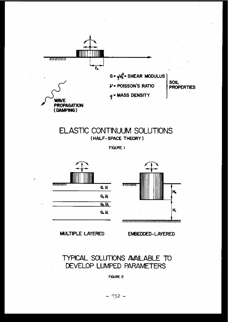
I[[[1T1Tfi
ro
G =9
V = SHEAR MODULUS
V a POISSON 'S RATIO
z MASS DENSITY .
ELASTIC CONTINUUM SOLUTIONS(HALF- SPACE THEORY )
FIGURE I
MULTIPLE LAYERED
EMBEDDED-LAYERED
TYPICAL SOLUTIONS AVAILABLE TODEVELOP LUMPED PARAMETER S
FIGURE 2
WAVEPROPAGATION(DAMPING)
SOILPROPERTIES
-152 -
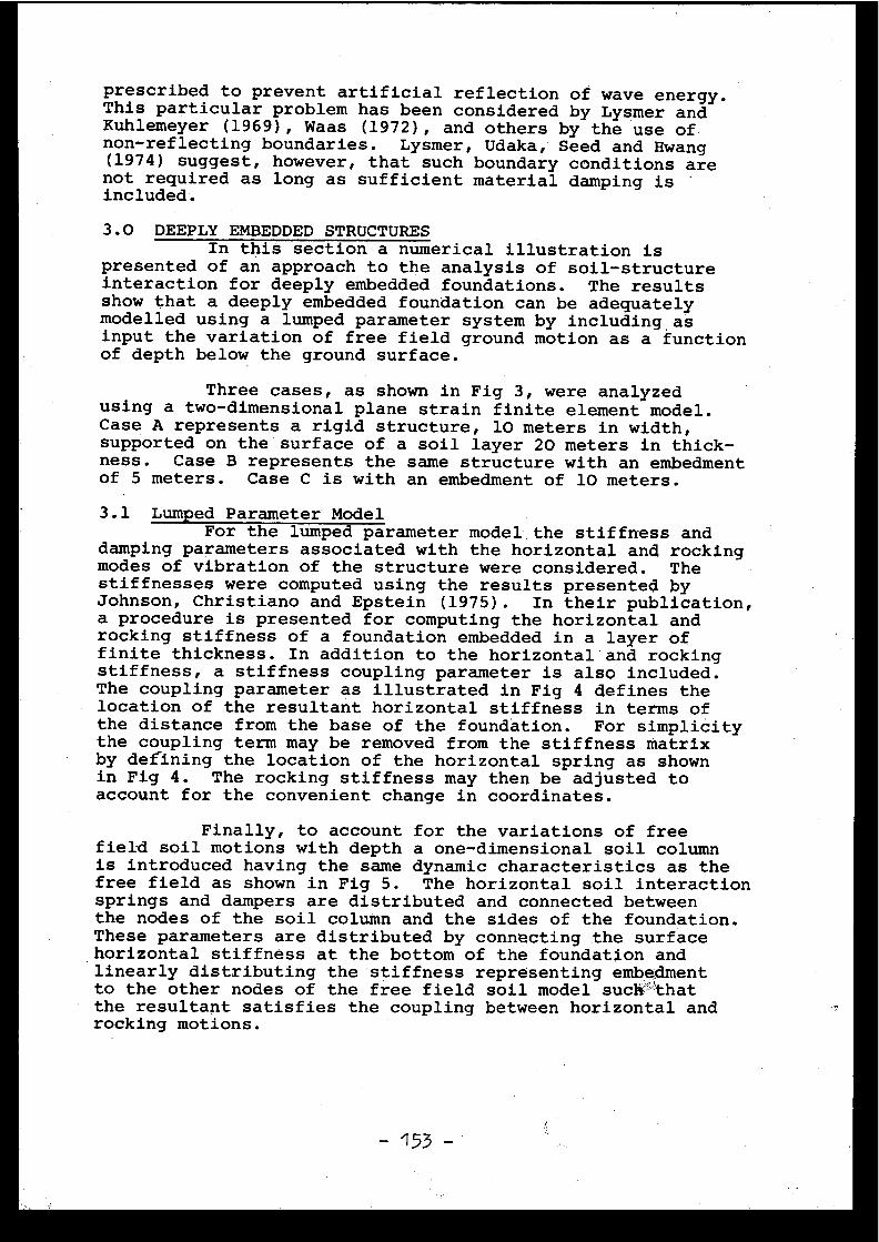
prescribed to prevent artificial reflection of wave energy .This particular problem has been considered by Lysmer an dKuhlemeyer (1969), Waas (1972), and others by the use o fnon-reflecting boundaries . Lysmer, Udaka, Seed and Hwang(1974) suggest, however, that such boundary conditions ar enot required as long as sufficient material damping i sincluded.
3 .0 DEEPLY EMBEDDED STRUCTURESIn this section a numerical illustration i s
presented of an approach to the analysis of soil-structur einteraction for deeply embedded foundations . The result sshow that a deeply embedded foundation can be adequatel ymodelled using a lumped parameter system by includin g , asinput the variation of free field ground motion as a functio nof depth below the ground surface .
Three cases, as shown in Fig 3, were analyze dusing a two-dimensional plane strain finite element model .Case A represents a rigid structure, 10 meters in width ,supported on the surface of a soil layer 20 meters in thick -ness . Case B represents the same structure with an embedmentof 5 meters . Case C is with an embedment of 10 meters .
3 .1 Lumped Parameter Mode lFor the lumped parameter model the stiffness an d
damping parameters associated with the horizontal and rockin gmodes of vibration of the structure were considered. Thestiffnesses were computed using the results presented b yJohnson, Christiano and Epstein (1975) . In their publication ,a procedure is presented for computing the horizontal an drocking stiffness of a foundation embedded in a layer o ffinite thickness . In addition to the horizontal - and rockingstiffness, a stiffness coupling parameter is also included .The coupling parameter as illustrated in Fig 4 defines th elocation of the resultant horizontal stiffness in terms o fthe distance from the base of the foundation . For simplicitythe coupling term may be removed from the stiffness matri xby defining the location of the horizontal spring as show nin Fig 4 . The rocking stiffness may then be adjusted toaccount for the convenient change in coordinates .
Finally, to account for the variations of fre efield soil motions with depth a one-dimensional soil colum nis introduced having the same dynamic characteristics as th efree field as shown in Fig 5 . The horizontal soil interactionsprings and dampers are distributed and connected betwee nthe nodes of the soil column and the sides of the foundation .These parameters are distributed by connecting the surfac ehorizontal stiffness at the bottom of the foundation an dlinearly distributing the stiffness representing embedmen tto the other nodes of the free field soil model suc thatthe resultant satisfies the coupling between horizontal an drocking motions .
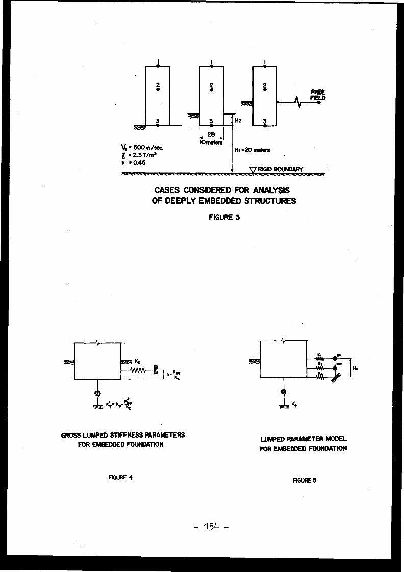
= 500m/sec.= 2.3 T/n s
Y =0.45
/ In/ n /nnrnrmnmrmnnrmmrminnnnnnnimrrnnrrnrni nrrrr rrn .nmmnsrr.,ovin,r, ,,,mai.
CASES CONSIDERED FOR ANALYSISOF DEEPLY EMBEDDED STRUCTURES
FIGURE 3
GROSS LUMPED STIFFNESS PARAMETERSFOR EMBEDDED FOUNDATION
LUMPED PARAMETER MODELFOR EMBEDDED FOUNDATIO N
FIGURE 4 FIGURE 5
- 154 -
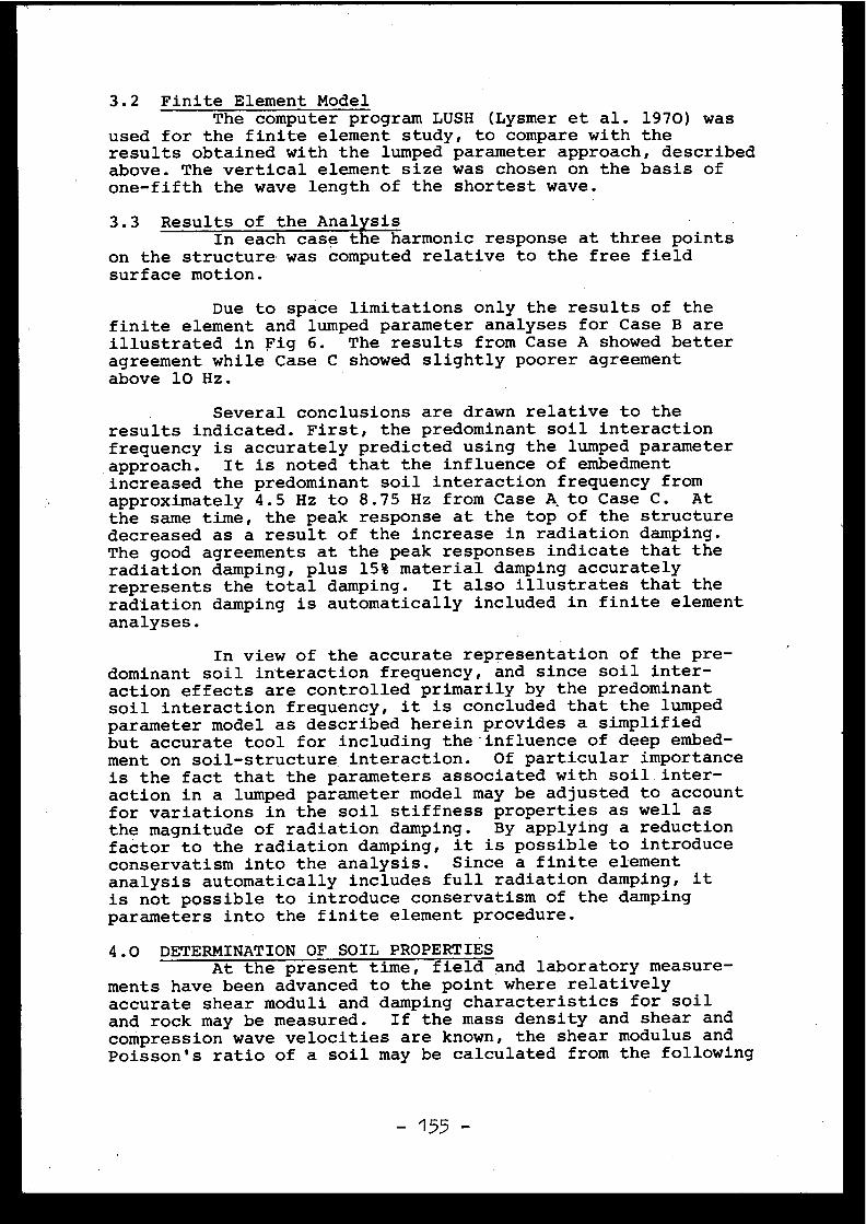
3 .2 Finite Element Mode lThe computer program LUSH (Lysmer et al . 1970) was
used for the finite element study, to compare with th eresults obtained with the lumped parameter approach, describe dabove . The vertical element size was chosen on the basis o fone-fifth the wave length of the shortest wave .
3 .3 Results of the Analysi sIn each case the harmonic response at three point s
on the structure was computed relative to the free fiel dsurface motion .
Due to space limitations only the results of th efinite element and lumped parameter analyses for Case B ar eillustrated in Fig 6 . The results from Case A showed bette ragreement while Case C showed slightly poorer agreemen tabove 10 Hz .
Several conclusions are drawn relative to th eresults indicated. First, the predominant soil interactionfrequency is accurately predicted using the lumped paramete r,approach . It is noted that the influence of embedmentincreased the predominant soil interaction frequency fro mapproximately 4 .5 Hz to 8 .75 Hz from Case & to Case C . Atthe same time, the peak response at the top of the structur edecreased as a result of the increase in radiation damping .The good agreements at the peak responses indicate that th eradiation damping, plus 15% material damping accuratel yrepresents the total damping . It also illustrates that th eradiation damping is automatically included in finite elemen tanalyses .
In view of the accurate representation of the pre -dominant soil interaction frequency, and since soil inter -action effects are controlled primarily by the predominan tsoil interaction frequency, it is concluded that the lumpe dparameter model as described herein provides a simplifie dbut accurate tool for including the-influence of deep embed -ment on soil-structure interaction . Of particular importanc eis the fact that the parameters associated with soil inter -action in a lumped parameter model may be adjusted to accoun tfor variations in the soil stiffness properties as well a sthe magnitude of radiation damping . By applying a reductionfactor to the radiation damping, it is possible to introduc econservatism into the analysis . Since a finite elementanalysis automatically includes full radiation damping, i tis not possible to introduce conservatism of the dampin gparameters into the finite element procedure .
4 .0 DETERMINATION OF SOIL PROPERTIE SAt the present time, field and laboratory measur e-
ments have been advanced to the point where relativel yaccurate shear moduli and damping characteristics for soi land rock may be measured . If the mass density and shear an dcompression wave velocities are known, the shear modulus an dPoisson's ratio of a soil may be calculated from the followin g
- 155 -
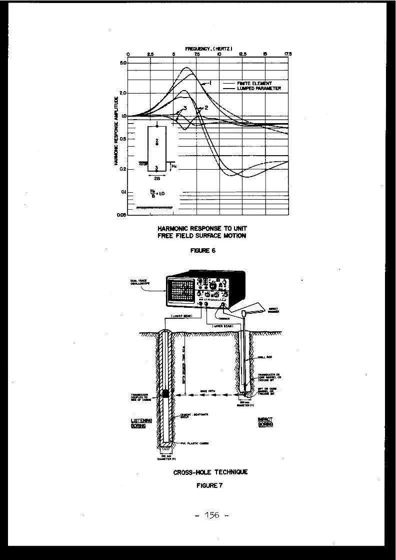
5.0
QI
0.05
FïEOUENCY,(FERTZ )5
1..5
10
I2.5
I5
It5
rAIL
~~M - PRATE ELEMENTPARAMETERUJMPED
=MI i-----
2 B
B ` 1.0-
i
HARMONIC RESPONSE TO UNITFREE FIELD SURFACE MOTION
FIGURE 6
)OO .DIAMETER (f)
CROSS-HOLE TECHNIQUE
FIGURE T
0 2.5
-156 -
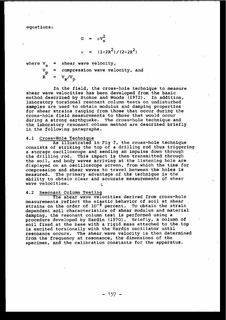
equations:
G = p V
v = (1-2R2 )/(2-2R2 )
where Vs = shear wave velocity ,
Vp = compression wave velocity, and
R = Vs/Vp
In the field, the cross-hole technique to measur eshear wave velocities has been developed from the basi cmethod described by Stokoe and Woods (1972) . In addition ,laboratory torsional resonant column tests on undisturbe dsamples are used to obtain modulus and damping propertie sfor shear strains ranging from those that occur during th ecross-hole field measurements to those that would occu rduring a strong earthquake . The cross-hole technique an dthe laboratory resonant column method are described briefl yin the following paragraphs .
4 .1 Cross-Hole TechniqueAs illustrated in Fig 7, the cross-hole techniqu e
consists of striking the top of a drilling rod thus triggerin ga storage oscilloscope and sending an impulse down throug hthe drilling-rod . This impact is then transmitted throughthe soil, and body waves arriving at the listening hole ar edisplayed on an oscilloscope screen, from which the time fo rcompression and shear waves to travel between the holes i smeasured . The primary advantage of the technique is theability to obtain clear and accurate measurements of shea rwave velocities .
4 .2 Resonant Column Testin gThe shear wave velocities derived from cross-hol e
measurements reflect the elastic behavior of soil at shea rstrains on the order of 10- 4 percent . To obtain the straindependent soil characteristics of shear modulus and materia ldamping, the resonant column test is performed using aprocedure developed by Hardin (1970) . Briefly, a column o fsoil fixed at the base with a rigid mass attached to the to pis excited torsionally with the Hardin oscillator unti lresonance occurs . The shear wave velocity is then determine dfrom the frequency at resonance, the dimensions of th especimen, and the calibration constants for the apparatus .
2s
REFERENCES
1.
Hardin, B .O ., "Shear Modulus and Damping of Soils by th eResonant Column," Special Procedures for Testing Soil an dRock for Engineering Purposes, ASTM, STP479, 1970 .
2.
Johnson, G .R ., P .P . Christiano and H .I . Epstein, " Stiff-ness Coefficients for Embedded Foundations," Journal ofthe Geotechnical Engineering Division, ASCE, Vol . 101 ,No . GT8, August 1975 .
3.
Lysmer, J . and R .L . Kuhlemeyer, "Finite Dynamic Model fo rInfinite Media," Journal of the Engineering Mechanic sDivision, ASCE, Vol . 95, No . EM4, August 1969 .
4.
Lysmer, J ., T . Udaka, H .B . Seed and R . Hwang, "LUSH : AComputer Program for Complex Response Analysis of Soi lStructure Systems," Report No . EERC 74-4, EarthquakeEngineering Research Center, University of California ,Berkeley, April 1974 .
5.
Richart, F .E ., Jr ., J .R . Hall, Jr . and R .D . Woods ,Vibrations of Soils and Foundations, Prentice-Hall, Inc . ,New Jersey, 1970 .
6.
Stokoe, K .H . and R .D . Woods, "In Situ Shear Wave Velocityby Cross-Hole Method," Journal of the Soil Mechanics andFoundations Division, ASCE, Vol . 98, No . SM5, May 1972 .
7.
Waas, G, "Linear Two-Dimensional Analysis of Soi lDynamics Problems in Semi-Infinite Media, " Thesi spresented to the University of California, Berkeley, i npartial fulfillment of the requirements for the degree ofDoctor of Philosophy, 1972 .

Discussions
M. LIVOLANT, Franc e
Pour les fondations de grande dimension, avez-vou sétudié les effets de la propagation des ondes, qui peuven tdevenir importants lorsque la longueur d'onde devient compa-rable au diamètre de la fondation ?
J .R . HALL, United State s
It is the present practice that the wave-lengt heffects are not considered . However recent studies indicat ethat this is a conservative assumption . A reduction in inputto the structure will occur for horizontally propagating sur -face waves . Other presentations at this meeting discuss thisproblem in more detail .
H . MAURER, CEC
Mr. Hall applied the infinite element approach andthe lumped parameter technique to the same model of soil -structure interaction. Does he have a preference for the appli-cation of the one or the other method depending on the comple -xity of the situation to be analysed ?
J .R . HALL, United State s
My preference is to use the lumped parameter mode lwhenever it is appropriate since it affords greater opportuni -ty to study effects of variations of soil properties (para-metric studies) . Also conservatism is easily introduced througha reduction in radiation damping . This is not possible in afinite element model since full radiation damping is automati -cally included .
It is important to note that both techniques wil lgive equally accurate results when properly used . Only inunusually complex soil conditions is it necessary to considerextensive finite elements studies .
[3 .2 ]
SEISMIC RESPONSE DUE TO TRAVELLING SHEAR WAVE INCLUDING SOIL-STRUCTUR EINTERACTION WITH BASE-MAT UPLIF T
J .P . Wol fElectrowatt Engineering Services Ltd .
P .O .Box CH-8022 Züric hSwitzerlan d
Abstract
The seismic response due to a travelling shear wave is investigated . Th eresulting input consists of a translational - and a torsional-acceleratio ntime history . The combined result of the translational and torsional elas-tic response (the latter arises even in an axi-symmetric structure) wil lnot, in general, be larger than that encountered in the case of a spatial-ly uniform earthquake . If the footing slips or becomes partially separate dfrom the soil, a nonlinear dynamic analysis is performed . Substantial mo -tions in all three directions will take place . A nuclear-reactor buildin gis used for illustration . The peak structural responses and the floor -response spectra are found to be highly nonlinear for high acceleration in -put values .
L'étude porte sur la réponse dynamique à une onde de cisaillement en mouvement ,d'origine séismique . La sollicitation est caractérisée par deux accéléro-grammes, l ' un de translation, l'autre de torsion . La réponse combinée au x
deux sollicitations est généralement du même ordre que la réponse à un echarge séismique de répartition géométrique uniforme . Mais on remarqueraque la torsion apparaît même si la structure est axisymétrique . Un éventue lsoulèvement ou glissement du radier est également pris en considération àl ' aide d ' une analyse non-linéaire . On observe de grandes réponses dans le strois directions . L'application porte sur un bâtiment de réacteur . La ré-ponse maximum et le spectre de réponse du radier sont fortement non-liné -aire pour des accélérations élevées .
- 160 -
1 . Introduction
It is normally assumed in the seismic analysis of structures that the free -field motion which is used as input is the same for all points on a give nlevel beneath the foundation mat . This represents a simplification, as not .all particles of soil describe the same motion simultaneously . As the foun-dation mat of the structure is rather rigid in the horizontal direction, i twill tend to average the ground motion, forcing the particles of soil i ncontact with the mat to displace as a rigid body . Abandoning the assumptionof the uniformity of the input motion will generally lead to a reduction o fthe translational motion which a foundation mat will experience, as the dis -placement components will cancel each other to a certain extent . In addi-tion, torsional effects will arise if the direction of wave propagation an dseismic motion do not coincide, as with shear waves . To form a rationa lbase for the investigation of these effects, the extremely complex pheno-menon of the passage of a seismic wave has to be simplified considerably .Newmark [1, 2] and Shah et al . [3] examine the torsional response of a sym-metrical building due to a travelling shear wave . Soil-structure interac-
tion is not accounted for . Scanlan [4] shows that averaging a passing com -pressive wave for which the directions of wave propagation and seismic mo -tion coincide results in a different effective "single-point" earthquake ,which shakes the structure in the classical manner used for seismic analy -sis (shaking table) . The reduction of the motion due to the "self-cancell-ing" effect, when integrated over the foundation mat, depends on the rati oof the wave length to the dimension of the mat . Formulae are specifiedbased on modelling the soil with constant distributed springs . In addition ,conclusions for the passage of a shear wave are stated .
Expanding the work of Scanlan [4], the resulting translational and torsion-al excitations of a circular foundation mat caused by the passage of a shearwave are determined in Section 2 . The elastic half-space is modelled wit han interconnected system of springs and dashpots (Fig .1) . The horizonta lmotion which is input is exerted at those ends of the springs and dashpot swhich are not connected to the foundation mat . The wave propagates in thehorizontal plane in a direction transverse to the input motion .
For higher acceleration values tension can occur in part of the area of con -tact between the foundation mat and the soil . As tension is incompatiblewith the constitutive laws of soils, the base mat will become partially sep-arated from the underlying soil . Slipping can also occur . Assuming that onlynormal stresses in compression and corresponding shear stresses (friction )can be transmitted in the area of contact, a method of analyzing soil-struc-ture interaction including partial lifting-off can be derived as outline din Ref . [5] and described in depth in Ref . [6] . This procedure, consistingof a nonlinear dynamic analysis based on complex influence coefficients is 'generalized in Section 3 to account for input motions which differ spatial-ly . An axi-symmetric structure's response due to a travelling shear waveconsists of not only a translational motion in the direction of the inpu tand of a torsional motion but also, due to uplift and slipping, transla-tional motions in the two other directions .
In Section 4, the dynamic response of an axi-symmetric reactor building i sdetermined . The results, consisting e .g . of the total overturning moment ,the peak structural responses and the floor-response spectra, of an analy-sis based on the familiar assumption of a single-point time history (spa -
- 161 -
tially uniform earthquake) are compared to those of a travelling shear wav ewhich describes the same motion .
A summary and conclusions are included in the last Section .
2 . Averaged Seismic Input Motion s
The soil-structure interaction model for a shear wave u g (y,t) travelling inthe y-direction and causing seismic excitation of the free field in the x -direction is shown in Fig .1 . The system consisting of the rigid circula rfooting of radius r and the elastic half-space is discretized . The latte rcan be visualized as an interconnected system of springs kij and dashpot scij . The detailed derivation is given in Section 3 . In Fig .1, only th esprings and dashpots associated with the horizontal motion in the x-direc-tion are drawn . The discretized system is shown in Fig .1, as it has to beused when lifting-off and slipping are considered (Section 3) . Neglectin gthe effect of damping on the effective load vector, as is normally done ,the dashpots could be omitted for determining the averaged seismic inpu tmotions . In addition, the cross-coupling terms kij are not excited . Finally ,the (static) kii could be replaced by an analytical expression, which, i nfact, is done later on . The prescribed free-field ground motion ug(y,t )acts at that end of the springs and dashpots which is not connected to th ecircular footing . The springs and dashpots lie in a horizontal plane ; forthe sake of clarity of the figure, they are drawn vertically .
The equations of motion of a structural system with prescribed arbitrar ymotions at the points of support are established next . The foundation matwill, in general, have a structure attached to it . The displacements {q }and the structural property matrices, the stiffness matrix [K], the dampin gmatrix [C] and the mass matrix [M], corresponding to the free nodes are ex -panded to account for the specified support motions {cis}, a vector made u pof all Ugi . The subscript s is used for the expanded matrices . As is wel lestablished in the literature, see e .g . [7], the equations of motion of th efree nodes not attached to the supports ar e
[M]•{q} + [C]•{q} + [K] . {q} = {R}
(1 )
A dot denotes differentiation with respect to time . The complete displace-ments of the free nodes {qc } are split up into the so-called quasi-stati cdisplacements {q} and the displacements {q} which are developed dynamically .
{q c } = {q} + {q }
{q} are calculated from the static relationshi p
{q} = -[K] -l . [K s ] • {qs}
(3 )
The effective load vector {R}, without the negligible influence of th edamping terms [7], is given b y
{R} = -[M]•{q} = [M]•[K]-1•[Ks]•{qS}
(4 )
In deriving Eq . 4, the mass-coupling term [M s ] is set equal to zero, whic his correct in our model of the soil-foundation system consisting of spring sand dashpots only . It follows that the response of a structure connecte dto a rigid foundation mat due to an arbitrary-acceleration time histor ywhich can be different at each support point, is determined by solving th efamiliar equations of motion (Eq . 1) withan averaged sing-le-point acceler-ation (Eq . 3) as effective load vector (Eq . 4) . The quasi-static displace -
(2 )
-162 -
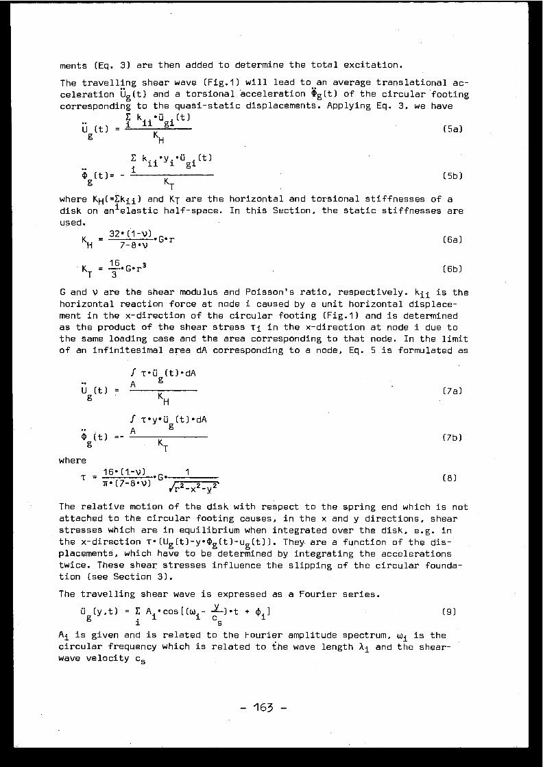
ments (Eq . 3) are then added to determine the total excitation .
The travelling shear wave (Fig .1) will lead to an average translational ac-celeration Ug(t) and a torsional . acceleration 'g(t) of the circular footin gcorresponding to the quasi-static displacements . Applying Eq . 3, we hav e
k . .•ü
(t )
U (t)= 1 11
gi
(5a )g
K
H
E k .11.•y i •U i (t )g
(t) = -1
(5b )g KT
where KH(=Ekii) and KT are the horizontal and torsional stiffnesses of adisk on an i elastic half-space . In this Section, the static stiffnesses ar eused .
KH =32•(1-V)•G•r
(6a )H
7-8• V
K = 16•G•r3T
3
G and V are the shear modulus and Poisson's ratio, respectively . kii is thehorizontal reaction force at node i caused by a unit horizontal displace -ment in the x-direction of the circular footing (Fig .1) and is determinedas the product of the shear stress Ti in the x-direction at node i due to
the same loading case and the area corresponding to that node . In the limitof an infinitesimal area dA corresponding to a node, Eq . 5 is formulated as
f T•0 (t)•dAA g
U (t) =g K
H
(6b )
(7a )
f T•y•üg (t)•dAA
KT(7b )
where
T =160(1.-v) •G• 1
(8 )w• (7-8•V)
Jr2_ x2_ y2 '
The relative motion of the disk with respect to the spring end which is no tattached to the circular footing causes, in the x and y directions, shea rstresses which are in equilibrium when integrated over the disk, e .g . i nthe x-direction T•(Ug(t)-y•(1)g(t)-ug(t)) . They. are a function of the dis -placements, which have to be determined by integrating the acceleration stwice . These shear stresses influence the slipping of the circular founda-tion (see Section 3) .
The travelling shear wave is expressed as a Fourier series .
ü g (y,t) = E A i •cos[(wi- 5)•t + (Pi ]
(9 )
Ai is given and is related to the Fourier amplitude spectrum, wi is th ecircular frequency which is related to the wave length X i and the shear -wave velocity c s
- 163 -
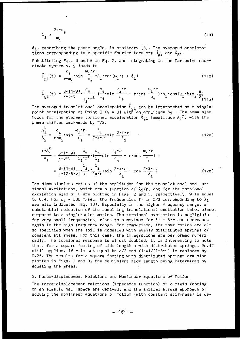
2Tr•cs
w .
(Pi, describing the phase angle, is arbitrary [8] . The averaged accelera-tions corresponding to a specific Fourier term are Ugi and agi .
Substituting Eqs . 9 and 6 in Eq . 7, and integrating in the Cartesian coor-dinate system x, y leads t o
c
W
1.• r
U gi (t) =
s sin
•A .•cos(w .•t + ]. )r•W .
cs 11
s
A .1 (10 )
(11a )
.(t) =6+(1-v)
cs
(Çs
sinwi • r
g1
7-8 •v •W •r3W .
c s11
, • rW1
Tr- r•cos c)•A 1.•cos(w
1.•t+~
i-)s
2 (11b )The averaged translational acceleration Uggi can be interpreted as a single -point acceleration at Point 0 (y = 0) with an amplitude Ait . The same alsoholds for the average torsional acceleration Ogi (amplitude A i r ) with thephase shifted backwards by 7/2 .
At c
w, r
1
s 1
1
2•Tr• r•sin
=
A . ,
r ow,
c S
2•Tr•r• sinÂ
1
1
rr
i = 6•(1-V)
c s
c s
wi • r•
• (-• s.
A .
7-8•V
Wi•r2W .
C s
3-(1-V) Xi
X i
2•Tr• rTr• (7-8•V) r • ( 2Tr•r
i n
The dimensionless ratios of the amplitudes for the translational and tor -sional excitations, which are a function of Ai/r, and for the torsiona lexcitation also of v are plotted in Figs . 2 and 3, respectively . V is equa lto 0 .4 . For cs = 500 m/sec, the frequencies fi in CPS corresponding to aiare also indicated (Eq . 10) . Especially in the higher frequency range, asubstantial reduction of the resulting translational excitation takes place ,compared to a single-point motion . The torsional excitation is negligibl efor very small frequencies, rises to a maximum for ai = 3•r and decrease sagain in the high-frequency range . For comparison, the same ratios are al -so specified when the soil is modelled with evenly distributed springs o fconstant stiffness . For this case, the integrations are performed numeri -cally . The torsional response is almost doubled . It is interesting to not ethat, for a square footing of side length a with distributed springs, Eq .1 2still applies, if r is set equal to a/2 and (1-v)/(7-8•v) is replaced by0 .25 . The results for a square footing with distributed springs are als oplotted in Figs . 2 and 3, the equivalent side length being determined b yequating the areas .
3 . Force-Displacement Relations and Nonlinear Equations of Motion
The force-displacement relations (impedance function) of a rigid footin gon an elastic half-space are derived, and the initial-stress approach ofsolving the nonlinear equations of motion (with constant stiffness) is de-
X .
- cos 2•A•r )
1
1
wi • r- r•cos
) =c s
(12a )
(12b )
- 164 -
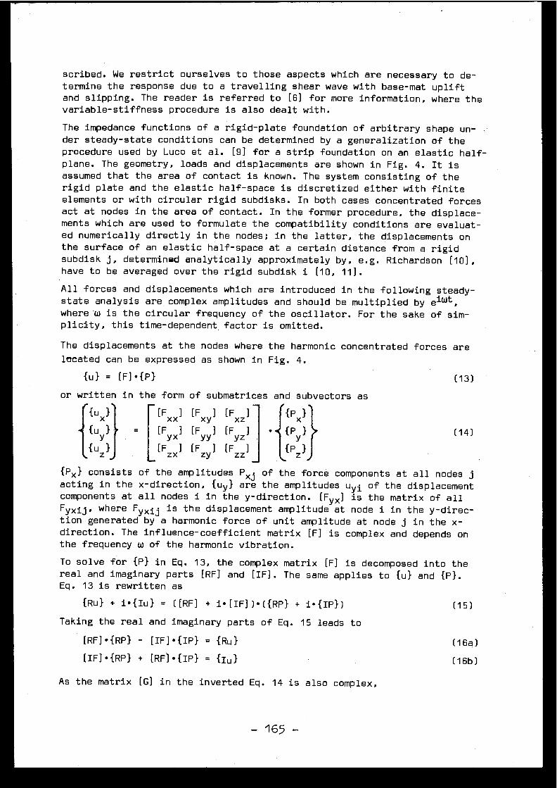
scribed . We restrict ourselves to those aspects which are necessary to de -termine the response due to a travelling shear wave with base-mat uplif tand slipping . The reader is referred to [6] for more information, where th evariable-stiffness procedure is also dealt with .
The impedance functions of a rigid-plate foundation of arbitrary shape un -der steady-state conditions can be determined by a generalization of th eprocedure used by Luco et al . [9] for a strip foundation on an elastic half -plane. The geometry, loads and displacements are shown in Fig . 4 . It isassumed that the area of contact is known . The system consisting of therigid plate and the elastic half-space is discretized either with finit eelements or with circular rigid subdisks . In both cases concentrated force sact at nodes in the area of contact . In the former procedure, the displace-ments which are used to formulate the compatibility conditions are evaluat-ed numerically directly in the nodes ; in the latter, the displacements o nthe surface of an elastic half-space at a certain distance from a rigi dsubdisk j, determined analytically approximately by, e .g . Richardson [10] ,have to be averaged over the rigid subdisk i [10, 11] .
All forces and displacements which are introduced in the following steady -state analysis are complex amplitudes and should be multiplied by e iwt ,
where w is the circular frequency of the oscillator . For the sake of sim-plicity, this time-dependent factor is omitted .
The displacements at the nodes where the harmonic concentrated forces ar elocated can be expressed as shown in Fig . 4 .
{u} = [F]•{P }
or written in the form of submatrices and subvectors a s
{u x }
{uy
f{uz
{Px } consists of the amplitudes Pxj of the force components at all nodes jacting in the x-direction, {uy} are the amplitudes uyi of the displacemen tcomponents at all nodes i in the y-direction . [Fy x ] is the matrix of al lFyxij, where Fyxij is the displacement amplitude at node i in the y-direc-tion generated by a harmonic force of unit amplitude at node j in the x -direction . The influence-coefficient matrix [F] is complex and depends o nthe frequency w of the harmonic vibration .
To solve for {P} in Eq . 13, the complex matrix [F] is decomposed into th ereal and imaginary parts
[RF] and
[IF] . The same applies to {u} and {P} .Eq . 13 is rewritten a s
{Ru}
+ i• {Iu}
=
([RF]
+
i•[IF])•({RP}
+ i•{IP}) (15 )
Taking the real and imaginary parts of Eq . 15 leads to
(16a )[RF]•{RP} -
[IF]•{IP} _ {Ru }
[IF]•{RP}
+
[RF]•{IP} _
{Iu} (16b)
As the matrix [G] in the inverted Eq . 14 is also complex ,
[Fxx] [Fxy ] [FxZ ]
[Fyx ] . [Fyy I [FyZ ]
[F] [F] [Fzx
zy
zz
(13 )
(14 )
- 165 -
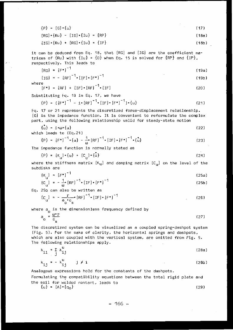
{P} = [G]•{u }
[RG]•{Ru} - [IG]•{Iu} = {Rp }
[IG]•{Ru} + [RG]•{Iu} = {Ip }
it can be deduced from Eq .
18, that
[RG]
and
[IG]
aretrices of {Ru} with {Iu} = {0} when Eq .
15 is solve drespectively . This leads to
th efor
coefficient ma -{RP} and {IP} ,
[RG]
=
[F*) -1 (19e )
[IG]
=
-
[RF]-1•[IF]•[F*]-1 (19b )where
[F*]
=
[RF]
+
[IF] • [RF] -1 • [IF] (20 )
Substituting Eq .
19 in Eq .
17, we have
{P}
=
([F * ] -1
-
i•[RF]-1•[IF]•[F*]-1) .{u} (21)
Eq . 17 or 21 represents the discretized force-displacement relationship .[G] is the impedance function . It is convenient to reformulate the comple xpart, using the following relationship valid for steady-state motio n
{u} = i•w•{u}
(22 )which leads to (Eq .21 )
{P} = [F * ] -1 •{u} - 1 --•[RF]-1•[IF]•[F*]-1•{u}
(23 )w
The impedance function is normally stated a s
{P} = [Ku]•{u} + [Cu]•{u}
(24 )
where the stiffness matrix [ K u ] and damping matrix [ Cu ] on the level of th esubdisks are
[K ] _ [F*] -1
(25a )u
[C] = - ! • [RF] -1 • [IF] • [F*] -1
(25b )u
wEq . 25b can also be written a s
[C u ] = - a ~ c •[RF]-1•[IF]•[F*]-1
(26 )o s
where ao is the dimensionless frequency defined b y
a = w• ro
c s
The discretized system can be visualized as a coupled spring-dashpot syste m(Fig . 5) . For the sake of clarity, the horizontal springs and dashpots ,which are also coupled with the vertical system, are omitted from Fig . 5 .The following relationships apply .
k . . = E k. .
(28a )ii
iJ
ikij = - k
j
i
(28b )K . .
Analogous expressions hold for the constants of the dashpots .
Formulating the compatibility equations between the total rigid plate an d
the soil for welded contact, leads t o{u} = [A]•{qo}
(29 )
(27 )
- 166 -
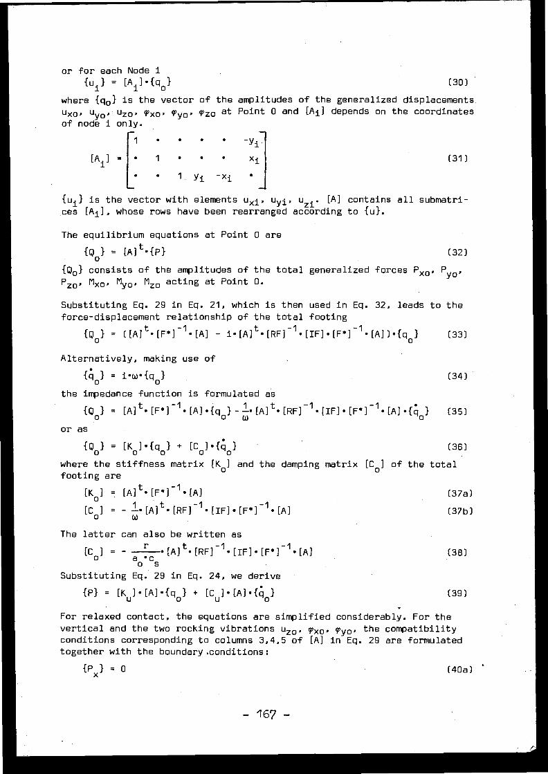
or for each Node i{u i } = [Ai ]•{qo }
(30 )
where {qo} is the vector of the amplitudes of the generalized displacements .
uxo , uyo , uz o , Txo , wyo• pzo at Point 0 and [Ai] depends on the coordinate sof node i only .
1
•
xi
• 1 . y i -xi
{ui } is the vector with elements u xi , uyi,uz1 . [A] contains all submatri-
ces [Ai ], whose rows have been rearranged according to {u} .
The equilibrium equations at Point 0 are
{Q0
} = [A] t •{P}
(32 )
{Qo } consists of the amplitudes of the total generalized forces Pxo, Pyo ,PzO, Mxo , Myo• Mzo acting at Point O .
Substituting Eq . 29 in Eq . 21, which is then used in Eq . 32, leads to theforce-displacement relationship of the total footin g
{Q0 } _ ([Al
i•[A ]t0[RF]-1•[IF] .[F *] -1•[A])•{ q
Alternatively, making use of
{qo } = i•w•{qo }
the impedance function is formulated a s
{Qo } = [A] t • [F* ] -I . [A] • {qo} - W. [A] t • [RF] -1. [IF]
. [F* ] -1 • [A] • { 40 }
(35 )
or as
{Qo } = [ Ko ]• { qo } + [Co]• {qo}
(36 )
where the stiffness matrix [ Ko] and the damping matrix [ Co ] of the tota lfooting are
[Ko]
[A] t • [F*]-1
• [A] (37a )
[ Co]
=
- -• [A] t • [RF]-1
• [IF] • [F* ]-1
• [A] (37b )
The latter can also be written as
(38 )
(39 )
[C]
=
-
• [A] t • [RF]-1 • [IF] •~ [F*] -1 . [A ]o
ca
Substitutingo
sEq . 29 in Eq . 24, we derive
{P}
=
[Ku]•[A]•{qo}
+
[Cu]•[A]•{qo}
For relaxed contact, the equations are simplified considerably . For th evertical and the two rocking vibrations uz0, Txo , Tyo, the compatibilityconditions corresponding to columns 3,4,5 of [A] in Eq . 29 are formulatedtogether with the boundary .conditions :
{Px } = 0
(40a )
(31 )
(33 )
(34 )
- 167 -
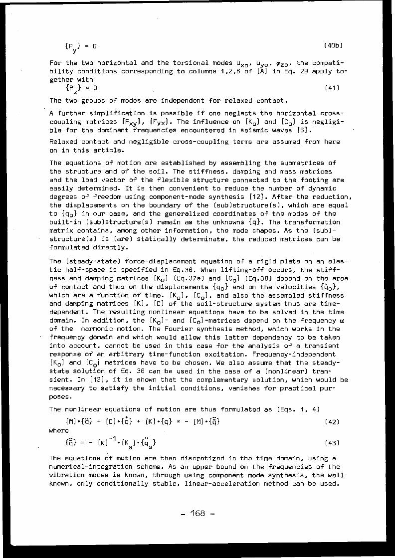
{ Py } = o
(40b )
For the two horizontal and the torsional modes u xo , uyo, 9zo• the compati-bility conditions corresponding to columns 1,2,6 of [A] in Eq . 29 apply t o -gether wit h
{Pz} = 0
(41 )
The two groups of modes are independent for relaxed contact .
A further simplification is possible if one neglects the horizontal cross -coupling matrices [Fxy], [Fyx] . The influence on [K o ] and [C o ] is negligi-ble for the dominant frequencies encountered in seismic waves [6] .
Relaxed contact and negligible cross-coupling terms are assumed from her eon in this article .
The equations of motion are established by assembling the submatrices o fthe structure and of the soil . The stiffness, damping and mass matricesand the load vector of the flexible structure connected to the footing ar eeasily determined . It is then convenient to reduce the number of dynami cdegrees of freedom using component-mode synthesis [12] . After the reduction ,the displacements on the boundary of the (sub)structure(s), which are equa lto {qo} in our case, and the generalized coordinates of the modes of th ebuilt-in (sub)structure(s) remain as the unknowns {q} . The transformationmatrix contains, among other information, the mode shapes . As the (sub) -structure(s) is (are) statically determinate, the reduced matrices can b eformulated directly .
The (steady-state) force-displacement equation of a rigid plate on an elas -tic half-space is specified in Eq .36 . When lifting-off occurs, the stiff-ness and damping matrices [Ko] (Eq .37a) and [Co] (Eq .38) depend on the are aof contact and thus on the displacements {qo} and on the velocities {q o} ,which are a function of time . [Ko ], [C o ], and also the assembled stiffnes sand damping matrices [K], {Cl of the soil-structure system thus are time -dependent . The resulting nonlinear equations have to be solved in the tim edomain . In addition, the [Ko]- and [Co]-matrices depend on the frequency wof the harmonic motion . The Fourier synthesis method, which works in th efrequency domain and which would allow this latter dependency to be take ninto account, cannot be used in this case for the analysis of a transien tresponse of an arbitrary time-function excitation . Frequency-independen t[Ko] and [Co ] matrices have to be chosen . We also assume that the steady -state solution of Eq . 36 can be used in the case of a (nonlinear) tran -sient . In [13], it is shown that the complementary solution, which would b enecessary to satisfy the initial conditions, vanishes for practical pur -poses .
The nonlinear equations of motion are thus formulated as (Eqs . 1, 4 )
[M]•{q}
+
[C] . { q }
+
[K]•{q}
_where
-
[M]•{q} (42 )
{q}
=
-
[K]-1•[Ks]•{qs} (43)
The equations of motion are then discretized in the time domain, using anumerical-integration scheme . As an upper bound on the frequencies of th evibration modes is known, through using component-mode synthesis, the well -known, only conditionally stable, linear-acceleration method can be used .
- 168 -
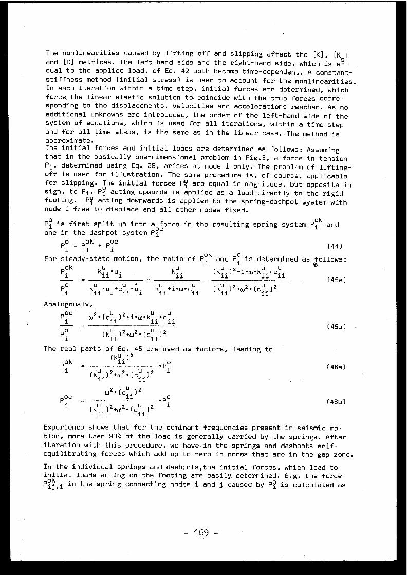
The nonlinearities caused by lifting-off and slipping affect the [K], [K s ]and (C] matrices . The left-hand side and the right-hand side, which is e -qual to the applied load, of Eq . 42 both become time-dependent . A constant-stiffness method (initial stress) is used to account for the nonlinearities .In each iteration within a time step, initial forces are determined, whic hforce the linear elastic solution to coincide with the true forces corre-sponding to the displacements, velocities and accelerations reached . As n oadditional unknowns are introduced, the order of the left-hand side of th esystem of equations, which is used for all iterations, within a time ste pand for all time steps, is the same as in the linear case . The method isapproximate .The initial forces and initial loads are determined as follows : Assumingthat in the basically one-dimensional problem in Fig .5, a force in tensio nPi, determined using Eq . 39, arises at node i only . The problem of lifting -off is used for illustration . The same procedure is, of course, applicabl efor slipping . The initial forces P4 are equal in magnitude, but opposite insign, to Pi . Pi acting upwards is applied as a load directly to the rigi dfooting . Py acting downwards is applied to the spring-dashpot system wit hnode i free to displace and all other nodes fixed .
Pi is first split up into a force in the resulting spring system P°k and
one in the dashpot system Pic
° = Pok +
PiP1
i
i
(44 )
For steady-state motion, the ratio of P°. k and
is is determined as follows :
P°k
k . .•u .
ku .
(k . .)2-i•w•ku .•c .u
1
11 1
11
11
11 1 1o
u
u
u
u
u 2 2
u 2P,
k . • u .+c . •u .
k . +i•w•c .
(k . ) +w •(c . . )1
11 1 1i 1
1i
ii
1i
i i
Analogously ,
Pi°
w2•(c i )2+i • w'kii• cli
P0
(ki)2+w2•(ci ) 2
The real parts of Eq . 45 are used as factors, leading t oPok -
(kli)2
Po1
(ku .)2+w2•(cu .)2 • 111
11
w2 •(cu. .) 2Poc =
11
Po
(ku) 2+w2 •(cu .) 21i
1 1
Experience shows that for the dominant frequencies present in seismic mo -tion, more than 90% of the load is generally carried by the springs . Afte riteration with this procedure, we have in the springs and dashpots self -equilibrating forces which add up to zero in nodes that are in the gap zone .
In the individual springs and dashpots,the initial forces, which lead t oinitial loads acting on the footing are easily determined . E .g . the forc eP°~ ,i in the spring connecting nodes i and j caused by P4 is calculated a s
(45a )
(45b )
(46a )
(46b)
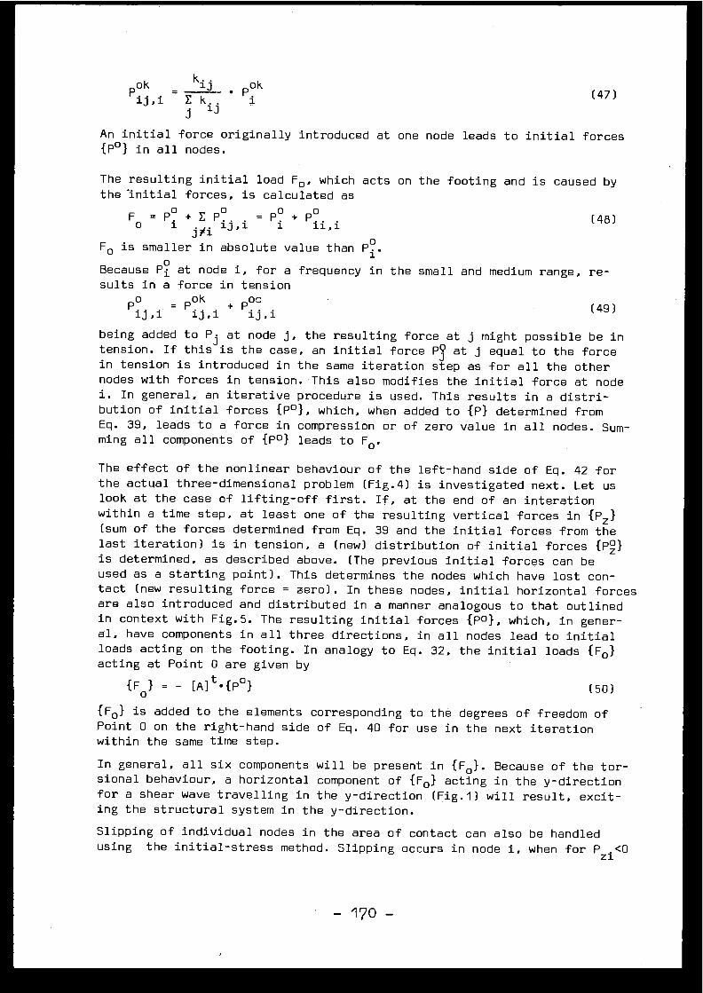
Pok
= kij
Pok
13 , 1
EkijJ.
An initial force originally introduced at one node leads to initial force s{P°} in all nodes .
The resulting initial load F° , which acts on the footing and is caused bythe 'initial forces, is calculated a s
Fo
P °. + E Pi .
= P° + P°. .
(48 )O
1 ixi 1 ,],1
1
11, 1
F° is smaller in absolute value than P .
Because Pi at node i, for a frequency in the small and medium range, re-sults in a force in tension
Poij,i =
Pok
Poc
(49 )ij,1
ij, i
being added to P i at node j, the resulting force at j might possible be i ntension . If this is the case, an initial force P3 at j equal to the forc ein tension is introduced in the same iteration step as for all the othe rnodes with forces in tension . This also modifies the initial force at nod ei . In general, an iterative procedure is used . This results in a distri-bution of initial forces {P°}, which, when added to {P} determined fro mEq . 39, leads to a force in compression or of zero value in all nodes . Sum-ming all components of {P°} leads to Fo .
The effect of the nonlinear behaviour of the left-hand side of Eq . 42 forthe actual three-dimensional problem (Fig .4) is investigated next . Let uslook at the case of lifting-off first . If, at the end of an interatio nwithin a time step, at least one of the resulting vertical forces in {Rd(sum of the forces determined from Eq . 39 and the initial forces from thelast iteration) is in tension, a (new) distribution of initial forces {PZ}is determined, as described above . (The previous initial forces can b eused as a starting point) . This determines the nodes which have lost con -tact (new resulting force = zero) . In these nodes, initial horizontal force sare also introduced and distributed in a manner analogous to that outline din context with Fig .5 . The resulting initial forces {P o }, which, in gener-al, have components in all three directions, in all nodes lead to initia lloads acting on the footing . In analogy to Eq . 32, the initial loads {F ° }acting at Point 0 are given b y
{F° } = - LAJt•{Po}
(50 )
{Fo l is added to the elements corresponding to the degrees of freedom o fPoint 0 on the right-hand side of Eq . 40 for use in the next iteratio nwithin the same time step .
In general, all six components will be present in {F o l . Because of the tor-sional behaviour, a horizontal component of {F ° } acting in the y-directio nfor a shear wave travelling in the y-direction (Fig .1) will result, excit -ing the structural system in the y-direction .
Slipping of individual nodes in the area of contact can also be handle dusing the initial-stress method . Slipping occurs in node i, when for PZ1 <0
(47 )
- 170 -
V Pxi 2 + Pyi2
tgS'IPzl
(51 )
Pxi' Pyi' Pzi are determined as the sum of the forces obtained from Eq . 39 ,of the quasi-static forces (horizontal) and of the initial forces from th eprevious iteration . tg S is the coefficient of friction . The horizonta linitial force
, /Ph1 = tgS • IPzi I - V
Pxi2 +Pyi2
(52 )
is projected on the x- and y-axes . For all nodes with slipping, the distri-bution of initial forces acting in all nodes .{P°} and of initial loads {Folis determined in a manner analogous to that explained with Fig .5 .
Lifting-off and slipping also affect the average seismic input motio n(right-hand side of Eq .42, Eqs . 43, 5) which changes the component of th eload {R} in the direction of the seismic motion and the torsional loadingacting in all nodes of the structure . Eq . 5 is used, introducing the actua lvalues of kii , KH and KT at the end of an iteration within a time step . Al lnodes i which have lost contact are deleted from the sum . kii is determinedas follows
Pxi(53 )
Pxi is equal to the sum of the force calculated from Eq . 39 and the initia lforce .
After reaching convergence, the next time step is started . The initia lforces and loads determined in the last iteration of the previous time ste pcan be used as starting values .
To achieve faster convergence when calculating the example of Section 5 ,the iteration procedure, as described above, is modified somewhat, using acombination of over-correcting and averaging . The tolerance used for theunbalanced forces corresponds to 0 .4 t/m2 .
4 . Example
As an example, the reactor building shown in Fig .6 (Nuclear-Power Plant ,Leibstadt, Switzerland, General Electric Mark 3) is analyzed using the ac-celeration time history (maximum acceleration 0 .21 g) which reflects loca lsoil conditions (Fig .7) . The average shear modulus G is 6 . 104 t/m2 ,Poisson's ratio V equals 0 .4, and the density p is 0 .24 t•sec2 /m4 , result -ing in a shear-wave velocity c s of 500 m/sec . The friction coefficient tg Sis 0 .577 (S = 30°) . Material damping in the soil is chosen to be 5% criti-cal, the corresponding values for concrete and steel are 7% and 4%, re-spectively . The radius r of the foundation mat is 20 .3 m, the weight of th estructure 6 .3 . 10 4 t . Based on the approximate method of Ref . [6], partia llifting-off commences for a single-point earthquake when the overturnin gmoment Myo exceeds 6 .3 . 104 . 20 .3/3 = 4 .263 . 105 mt .
To be able to evaluate the vertical-influence coefficient matrix [Fzz ](Eq . 14), it is sufficient to calculate the displacements uzi at the sur-face nodes generated by a concentrated vertical load Pzj acting at just on epoint . For the horizontal impedance function [Fxx], a horizontal force Pxi
- 171 -
acting in one single point is applied . The axisymmetric finite-element meshis shown in Fig .8 . For a horizontal force, the first harmonic in the cir-cumferential direction 0 is used (see Fig .4) . The disk with radius r is al -so drawn . When determining [F] , which involves the soil only, the disk isnot included in the model . The finite-element model can cover only part o fthe semi-infinite foundation medium . A large model is selected (widt h=l60r ,height=18•r) . Artificial non-reflective boundaries, which trap all the en -ergy within a finite region [9], are introduced . The boundaries are fixed .To compensate for this box effect, a certain amount of material damping o fthe structural type is introduced to account for the radiation of energ ythat would otherwise take place in the elastic half-space . Damping is als onecessary to enable the imaginary part of [F] to be calculated . The dampingmatrix is assumed to be proportional to the stiffness matrix ; the factor ischosen so that for the frequency 3 .92 CPS the critical damping ratio of0 .08 results . The harmonic displacements uzi, caused by P zj, and ur , utcaused by P xj (Figs .4,10) are calculated for f = 3 .92 CPS (ao=1) . The realand imaginary parts are plotted for the magnitudes specified in Fig .9 .
In Fig .10, the discretization of the rigid disk is represented . On a dia -meter of the circle, 10 elements are chosen . The points in which the con -centrated forces Pxj, Pyj , Pzj and the displacements uri, u ti , uzi are de -fined, are situated in the centre of gravity of the elements . The valuesof [F] (Fig .9) are interpolated .
The impedance function is calculated as described in Section 3 . In additionto this finite-element solution, the frequency-dependent stiffness an ddamping coefficients are specified in Table 1, as determined in [14] fo rthe vertical motion,in [15] for the horizontal and rocking motions, neglect -ing the cross-coupling terms, and in [16] for the torsional motion . Thefrequency-independent values calculated as summarized in [17] are also list -ed (analog) . The hysteretic damping of the soil can be approximately ac -counted for . The increase in the damping matrix [AC 0 ] is given b y
[AC 0 ] = 2wD '[K s ]
(54 )
where [Ko] is the stiffness matrix, D = 0 .05 and w = 27 . 3 .92 . In Table 1 ,the total damping coefficients are listed in parentheses . The accuracycould be improved by using consistent energy-transmitting boundaries, whic hhowever would be beyond the scope of the present investigation [18] .
The shield building, the steel containment, the drywell and the pedesta lwith the reactor pressure vessel are regarded as substructures which ar econnected by the common foundation mat . The natural frequencies of the fourbuilt-in substructures are specified in Table 2 . The natural frequencies u pto the cut-off limit of 25 CPS calculated with the reduced system with 2 8degrees of freedom (2 . 9+4 built-in modes, 6 displacements {go} of founda-tion mat, see Fig .4) agrees well with the corresponding values of the tota lsystem with 354 degrees of freedom (Table 3) . The frequencies associate dwith bending occur twice .
In Fig .11, a part of the averaged translational input acceleration U g (t )(linear case), Eq .5a, is compared to the standard single-point input . Th ecorresponding curves for lift-off and for lift-off combined with slippin gare very similar to that of the linear case . A comparison of the respons espectra shows that the components in the medium- and higher-frequency rang e
- 172 -
(> 5 CPS) are appreciably reduced . The translational acceleration caused b ythe torsional excitation $g(t), Eq . 5b, at a distance of 10 m is also show nin Fig .11 .
The time step for the integration of the equations of motion is selected a s0 .01 sec . The maximum dynamic response of the reactor building is listed i nTable 4 for the foundation mat and in Table 5 for the steel containment .See Fig .4 for the nomenclature . The linear behaviour (no lifting-off and n oslipping, but with tension arising between the foundation mat and the soil )is compared to the various nonlinear responses, using the classical singl epoint excitation and the travelling shear wave as input . A shear wave, a scompared to a single-point excitation, leads to about 7% less translationa lresponse for linear behaviour ; the torsional moment Mzo corresponds to a n"accidental" eccentricity of the horizontal force P xo of between 5 and 8%of the diameter of the base mat . At the base of the steel containment, th eequivalent normal stress for linear behaviour, based on the yield criterio nof von Mises, is smaller for the travelling shear wave than for the single -point earthquake . For the loading case of horizontal earthquake plus dea dload, the nonlinear response caused by lifting-off and slipping is surpris-ingly similar to the linear results, although a substantial part of th efooting lifts off and slides (see Fig .12) . The relative displacements ar ein general increased slightly while the stress resultants are somewhat di -minished for lifting-off and for slipping . The response in the y-direction ,perpendicular to the excitation, can be neglected . For the loading case o ftwice the horizontal earthquake plus dead load, the behaviour is highl ynonlinear . For the case of lifting-off, the foundation mat and the stee lcontainment behave differently, as far as displacements and stress result -ants associated with the direction of excitation are concerned . The tor-sional response is increased substantially . The response in the y-directio nremains an order of magnitude smaller than in the x-direction . Slippingleads to larger displacements and smaller stress resultants in the direc-tion of excitation . The torsional moment Mzo is substantially larger . Mxois increased by an order of magnitude . Mxo , Myo and Mzo are of the sameorder of magnitude :
The lines of constant vertical pressure on the foundation mat at the tim eof the maximum overturning moment Myo are shown as solid lines in Figs .1 2and 13 for the loading case of horizontal earthquake plus dead load and fo rthat of twice horizontal earthquake plus dead load, respectively . An areawhich is shown shaded, undergoes slipping . In Fig .14 the lines of constan tresulting horizontal pressure, at the same instant in time, are specifie dfor the larger loading case . As expected, the horizontal pressure increase stowards the boundary of that part of the area of contact which behaves elas-tically .
Substantial slipping occurs before lifting-off takes place . In Fig .15, theareas of slipping for different points of time are indicated for the load -ing case of horizontal earthquake plus dead load .
The translational floor-response spectra in the direction of excitatio n(x-axis) for 0 .5% critical damping are plotted for the three calculation scarried out with the travelling shear wave (twice horizontal earthquak e
- 173 -
plus dead load) for the following locations : base mât (Fig .16), top of th epressur, vessel (Fig .17), and top of the steel containment (Fig .18) . Fo rcompa RIson, the response spectrum for the classical single-point excitatio nis also indicated . The response spectrum of the linear travelling shea rwave is reduced in the medium- and higher frequency range (>5cps), compare dto that of the spatially uniform earthquake . As pointed out in Ref . [6] ,partial separation of the base mat from the soil leads to a substantial am -plification in the same range of frequency . This is particularly the cas eat high elevations of stiff substructures, as e .g . at the top of the stee lcontainment (Fig .18) .
5. Summary and Conclusions1. The seismic response due to a travelling shear wave, a possible firs t
step towards a more realistic assumption than the commonly used spatial -ly uniform motion, is investigated . Averaging the effect of the trav-elling wave over the footing results in an effective single-point earth -quake, but with a translational- and a torsional-acceleration time his -tory as input, which depend on the ratio of the wavelength and the di-mension of the footing .
2. Because of the self-cancelling effect, the resulting translational inpu ttime history of a travelling shear wave will be smaller than that of aspatially uniform earthquake . This is especially true for the component swith high frequency . The torsional input is negligible for very smal lfrequencies, then rises substantially and decreases again in the high -frequency range .
3. The linear response of a typical axi-symmetric nuclear-reactor buildin g(with a separate footing) consists of a translational motion (with rock -ing) and a torsional motion . In general, the resulting stresses, ex-pressed as an equivalent value, and displacements will not be larger tha nthose encountered in an analysis based on a classical uniform single -point motion . The same also applies to the floor-response spectra . Es-pecially , in the range of high frequency, a substantial reduction is en -countered .
4. For higher acceleration values (of a spatially uniform earthquake), th efooting will become partially separated from the soil . A nonlinear dy-namic analysis, which can also account for slipping, has to be used t odetermine the response with lift-off, which, in addition, results in avertical motion . This procedure, which assumes that only normal stresse sin compression and corresponding shear stresses (friction) can be trans-mitted in the area of contact of the elastic half-space and the footing ,is generalized for non-uniform excitation . Because of the torsional ef-fect due to a travelling shear wave, the third translational motio n(with rocking) perpendicular to the direction of excitation is also in -troduced when lift-off or slipping occurs . The response thus consist sof translations and rotations in all three directions . Although, eve nfor low acceleration values (ti 0 .2 g), a substantial part of the footin gcan lose contact, the response is similar to the result based on a linea ranalysis, with the exception of floor-response spectra in the high-fre-quency range, where an increase takes place . For high acceleration s(ti 0 .4 g), however, the response is highly nonlinear . The response in al lthree directions is important .
- 174 -
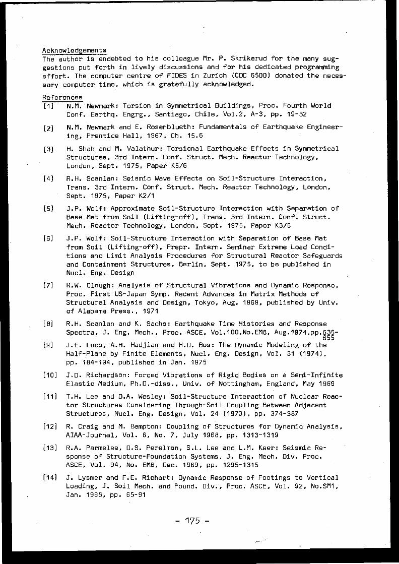
Acknowledgement sThe author is endebted to his colleague Mr . P . Skrikerud for the many sug-gestions put forth in lively discussions and for his dedicated programmin g
effort . The computer centre of FIDES in Zurich (CDC 6500) donated the neces-sary computer time, which is gratefully acknowledged .
Reference s
[1] N .M . Newmark : Torsion in Symmetrical Buildings, Proc . Fourth WorldConf . Earthq . Engrg ., Santiago, Chile, Vol .2, A-3, pp . 19-32
[2] N .M . Newmark and E . Rosenblueth : Fundamentals of Earthquake Engineer-ing, Prentice Hall, 1967, Ch . 15 . 6
[3] H . Shah and M . Valathur : Torsional Earthquake Effects in Symmetrica lStructures, 3rd Intern . Conf . Struct . Mech . Reactor Technology ,London, Sept . 1975, Paper K5/6
[4] R .H. Scanlan : Seismic Wave Effects on Soil-Structure Interaction ,
Trans . 3rd Intern . Conf . Struct . Mech . Reactor Technology, London ,Sept . 1975, Paper K2/ 1
[5] J .P . Wolf : Approximate Soil-Structure Interaction with Separation o fBase Mat from Soil (Lifting-off), Trans . 3rd Intern. Conf . Struct .Mech . Reactor Technology, London, Sept . 1975, Paper K3/6
[6] J .P . Wolf : Soil-Structure Interaction with Separation of Base Ma tfrom Soil (Lifting-off), Prepr . Intern . Seminar Extreme Load Condi-tions and Limit Analysis Procedures for Structural Reactor Safeguard sand Containment Structures, Berlin, Sept . 1975, to be published i nNucl . Eng . Design
[7] R .W. Clough : Analysis of Structural Vibrations and Dynamic Response ,Proc . First US-Japan Symp . Recent Advances in Matrix Methods o fStructural Analysis and Design, Tokyo, Aug . 1969, published by Univ .of Alabama Press ., 197 1
[8] R .H . Scanlan and K . Sachs : Earthquake Time Histories and Respons eSpectra, J . Eng . Mech ., Proc . ASCE, Vol .100,No .EM8, Au g .1 974 , pp • 6 3565 5
[9] J .E . Luco,A .H . Hadjian and H .D . Bos : The Dynamic Modeling of theHalf-Plane by Finite Elements, Nucl . Eng . Design, Vol . 31 (1974) ,pp . 184-194, published in Jan . 197 5
[10] J .D . Richardson : Forced Vibrations of Rigid Bodies on a Semi-Infinit eElastic Medium, Ph .D .-diss ., Univ . of Nottingham . England, May 196 9
[11] T .H . Lee and D .A . Wesley : Soil-Structure Interaction of Nuclear Reac-tor Structures Considering Through-Soil Coupling Between Adjacen tStructures, Nucl . Eng . Design, Vol . 24 (1973), pp . 374-387
[12] R . Craig and M . Bampton : Coupling of Structures for Dynamic Analysis ,AIAA-Journal, Vol . 6, No . 7, July 1968, pp . 1313-131 9
[13] R .A . Parmelee, D .S . Perelman, S .L . Lee and L .M . Keer : Seismic Re -sponse of Structure-Foundation Systems, J . Eng . Mech . Div . Proc .ASCE, Vol . 94, No . EM6, Dec . 1969, pp . 1295-131 5
[14] J . Lysmer and F .E . Richart : Dynamic Response of Footings to Vertica lLoading, J . Soil Mech . and Found . Div ., Proc . ASCE, Vol . 92, No .SM1 ,Jan . 1968, pp . 65-91
- 175 -

[15] A .S . Veletsos and Y .T . Wei : Lateral and Rocking Vibration of Footings ,J . Soil Mech . and Found . Div ., Proc . ASCE, Vol . 97, No . SM 9, Sept .1971, pp . 1227-1248
[16] M .P . Stallybrass : A Variational Approach to a Class of Mixed Bound -ary-Value Problems in the Forced Oscillations of an Elastic Medium ,Proc ., 4th U .S . National Congress on Applied Mechanics, 1962, pp . 391 -40 0
[17] F .E . Richart, R .D . Woods and J .R . Hall : Vibration of Soils and Founda-tions, Prentice Hall, 197 0
[18] E . Kausel, J .M . Roesset and G . Waas : Dynamic Analysis of Footings o nLayered Media, J . Eng . Mech . Div ., Proc . ASCE, Vol . 101, No . EM 5 ,Oct . 1975, pp . 679-693
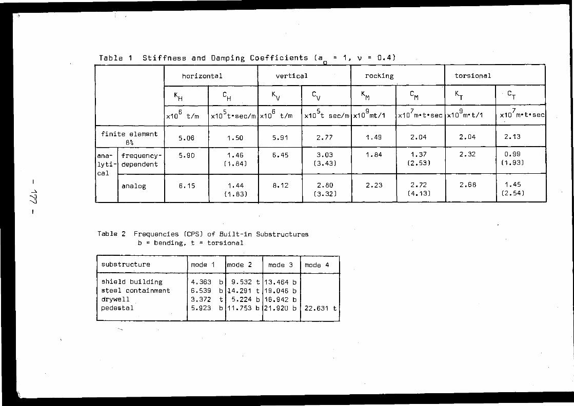
Table 1 Stiffness and Damping Coefficients (a~ = 1, v = 0 .4 )
horizontal vertical rocking torsiona l
KH CH Kv Cv KM CM KT CT
x10 6 t/m x10 5t•sec/m x106 t/m x10 5 t sec/m x10 9 mt/1 x107m•t•sec x109m•t/1 x10 7m•t•sec
finite element5 .06 1 .50 5 .91 2 .77 1 .49 2 .04 2 .04 2 .1 3
8%
ana- frequency- 5 .90 1 .46 6 .45 3 .03 1 .84 1 .37 2 .32 0 .99
lyti- dependent (1 .84) (3 .43) (2 .53) (1 .93 )
cal
analog 6 .15 1 .44 8 .12 2 .80 2 .23 2 .72 2 .68 1 .4 5
(1 .83) (3 .32) (4 .13) (2 .54)
Table 2 Frequencies (CPS) of Built-in Substructure sb = bending, t = torsiona l
substructure mode 1 mode 2 mode 3 mode 4
shield building 4 .363 b 9 .532 t 13 .464 bsteel containment 6 .539 b 14 .291 t 19 .046 bdrywell 3 .372 t 5 .224 b 16 .942 bpedestal 5 .923 b 11 .753 b 21 .920 b 22 .631 t
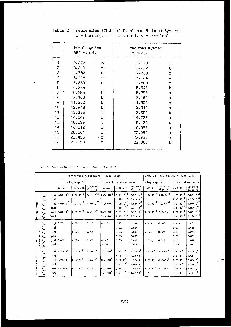
Table 3 Frequencies (CPS) of Total and Reduced System sb = bending, t = torsional, v = vertica l
total system
354 d .o .f .reduced system
28
d .o .f .
1 2 .377 b 2 .376 b2 3 .270 t 3 .277 t3 4 .782 b 4 .780 b
4 5 .418 v 5 .684 v5 5 .869 b 5 .869 b6 6 .255 t 6 .546 t7 6 .395 b 6 .395 b
8 7 .160 b 7 .152 b9 11 .382 b 11 .396 b
10 12 .948 b 13 .012 b
11 13 .385 t 13 .698 t12 14 .649 b 14 .727 b
13 16 .299 t 19 .428 t14 18 .312 b 18 .369 b15 20 .281 b 20 .590 b
16 22 .455 •
b 22 .936 b
17 22 .693 t 22 .888 t
Table 4 Maximum Dynamic Response (Foundation Mat)
horizontal earthquake + dead load 2•horiz .
earthquake + dead
loa d
single-point travelling shear wave single-point tray .
shear wav e
linear lift-off lift-offslipping linear lift-off lift-off
slipping lift-off lift-offslipping lift-off lift-off
slippin g
uxo
[m] 2 .33-10-3 2 .36 . 10 -3 2 .47-10-3 2 .18 . 10 -3 2 .19. 10 -3 2 .32-10-3 4 .97-10 -3 5 .76 . 10 -3 4 .75 . 10 -3 7 .66-10 - 3
m
u y0
[m]2 2
2 .27 . 10 -52
6 .60 . 10-52
6 .18 . 11
42
6 .25 . 10 -32u zO
(ml 1 .06. 10 1 .07 . 10 1 .07 . 10 1 .06 . 10 1 .06 . 10 1 .06 . 10 2 1 .07 . 10 1 .07 . 10 -2 1 .07 . 10 1 .07 . 1 0
g exo
[rad] 4 .11 . 10 -7 9 .74-10 -7 7 .37 . 10-6 1 .09 . 10 - 4
2 hyo
[rad] 3 .84. 10-4 3 .85-10 -4 3 .82-10-4 3 .62 . 10 -4 3 .63-10 -4 3 .53 . 10-4 7 .57-10 -4 7 .49-10-4 7 .22 . 10 -4 7 .30 . 10 - 4
azo
[rad] 2 .09 . 10 -5 2 .16 . 10 -5 2 .71-10-5 1 .44 . 10 -4 6 .14 . 10 - 4
üxo
[g] 0 .201 0 .201 0 .203 0 .183 0 .183 0 .185 0 .449 0 .468 0 .410 0 .48 1ü yo
[g] 0 .003 0.007 0 .092 0 .453üzO
[g] 0 .006 0 .005 0 .002 0 .002 0 .105 0 .103 0 .094 0 .085
c0. 'ix.
[g/m' 0 .000 0 .000 0 .002 0 .00 1m m 9' o
[g/m )y 0 .009 0 .009 0 .009 0 .008 0 .008 0 .008 0 .016• 0 .016 0 .015 0 .01 50 m ¢zo
[g/ m ] 0 .003 0 .003 0 .003 0 .019 0 .039
P
[t ]xo 1 .30. 104 1 .29 . 10 4 1 .23 . 104 1 .21 . 10 4 1 .22 . 104 1 .17 . 104 2 .27 . 104 2 .28 . 10 4 2 .21 . 104 2 .19 . 104N P
[t] 1 .24. 102 2 .23 . 10 2 2 .65 . 10 3 1 .51 . 104ûô yoP zo
[t] 46 .29 . 10 6 .32 . 10 4 6 .32 . 104 6 .29 . 10 4 6 .31 . 104 6 .30 . 104 6 .76 . 104 6 .75 . 104 6 .71 .104 6 .68 . 104
Mxo
[mt] 6 .98 . 10 2 1 .64 . 103 1 .22 . 104 1 .79 . 10 5
û M
[mt ]yo 5 .84 . 105 5 .70 . 10 5 5 .66 . 105 5 .51 . 10 5 5 .44 . 10 5 5 .40 .10 5 8 .04 . 10 5 8 .01 . 105 7 .91 . 10 5 7 .88 . 10 5T M
[nit) 4 .33 . 10 4 4 .24 . 10 4 4 .72 . 104 ' 3 .10 . 10 5 5 .44 . 10 52 zo
178 -
Table 5 Maximum Dynamic Response (Steel Containment )
horizontal earthquake t dead load 2•horiz .
earthquake * dead loa d
single-point travelling shear wave single-point tray . shear wav e
linear lift-off lift-offslipping linear lift-off lift-off
slipping lift-off lift-offslipping
lift-off lift-offslipping
u
In] 2 .98 . 10-2 2 .98 . 10 -2 2 .99 . 10-2 2 .82 . 10 -2 2 .82 . 10-2 2 .81 . 10-2 5 .61 . 10 -2 5 .61 . 10-2 5 .38 . 10-2 5 .94 . 10 2
c uyo
[m] 1 .96 . 10-5 6 .20. 10-5 5 .39 . 10-4 6 .46. 10 - 3
qxo
[ted] 5 .17 . 10-7 1 .19 . 10-6 9 .84 . 1 0-6 1 .27 . 10- 4
V [rad]-44 .22 . 10 4 .21 . 10-4 4 .18 . 10-4 3 .97 . 10 -4 3 .96 . 10-4 3 .94 . 10-4 8 .11 . 10 - 48 .04 . 10 -47 .74 . 10 -47 .91 . 1 0$
a ypyo
v , iv
[tad] 2 .52 . 10-5 2 .57 .10 5 3 .27 . 10-5 1 .50. 10-4 6 .70. 10-4
üxo
[g] 0 .557 0 .556 0 .547 0 .523 0 .528 0 .524 1 .437 1 .337 1 .356 1 .13 1
ü~
[g] 0 .006 0 .011 0 .160 0 .51 6
q
Ig/m] 0 .000 0 .000 0 .006 0 .02 28 X0i
[g/m] 0 .009 0 .009 0 .009 0 .009 0 .008 0 .008 0 .024 0 .023 0 .022 0 .02 3
0ô y 'zo
- [g/ml 0 .003 0 .003 0 .004 0 .040 0 .084
.m, Pxo
It] 5 .28 . 102 5 .17 . 102 4 .94 . 10 2 4 .95. 102 4 .93 . 10 2 4 .77 . 10 2 1 .27 . 10 3 1 .18 . 10 3 1 .20 . 10 3 1 .08 . 10 3
.c+ Pyo
[t] 6 .41 1 .35 . 10 1 1 .82 . 10 2 7 .73 . 10 2
m Mxo
NM 6 .53 . 10 1 .54 . 10 2 1 .52 . 103 1 .30 . 104ti M
NM 1 .96. 104 1 .89 . 104 1 .90 . 104 1 .85 . 104 1 .83. 104 1 .82 . 104 4 .83 . 10 4 4 .54 . 104 4 .48 . 104 4 .24 . 104m m
amYo
MzO
[mt] 1 .13 . 103 1 .08. 103 1 .39 . 10 3 1 .23 . 104 2 .56. 104rm o
Fig . 1 Soil-Structure Interaction Model fo ra Travelling Shear Wave
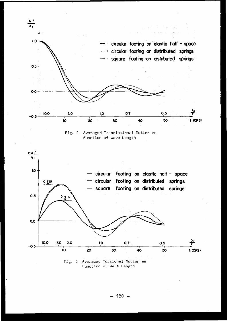
A i t
A i
1 .0- ° circular. footing on elastic half - space
circular footing on distributed springs
square footing on distributed springs
0.0
-0.52.0
I .0
IO
20
30 f i (CPS)
10.0 0 .5
Fig . 2 Averaged Translational Motion a sFunction of Wave Lengt h
r .A iA l
Fig . 3 Averaged Torsional Motion a sFunction of Wave Length
- circular footing on elastic half - spac e-- circular footing on distributed spring s- square footing on distributed spring s
50 f (CPS)
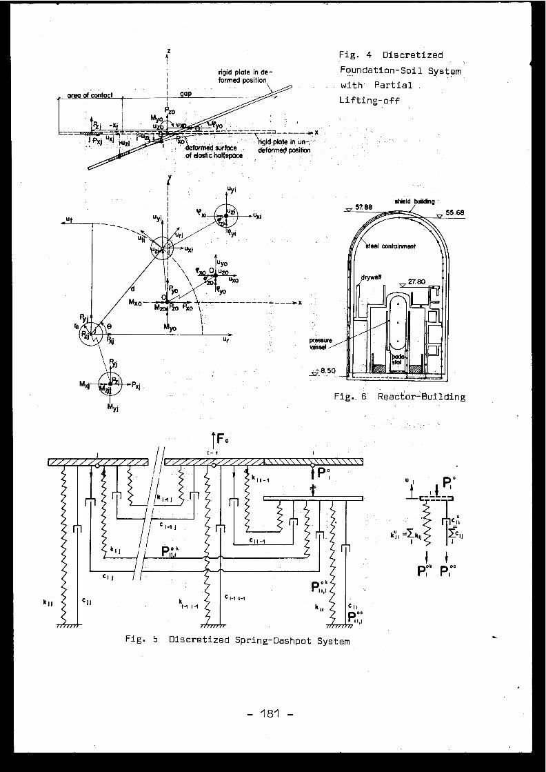
Fig . 4 Discretize d
Foundation-Soil System
with Partia l
Lifting-off
defaM ed surface
iigid plate in un-,
of elastic hatfspoce
deformed positio n
Fig . 5 Discretized Spring-Dashpot System
- 181 -
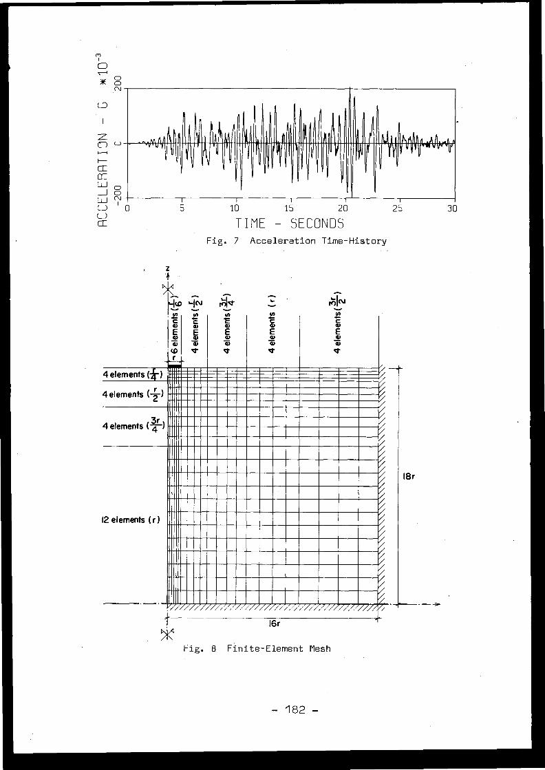
OON
z4'
1*
i
46 f
10
15
20
25
30
TIME - SECOND SFig . 7 Acceleration Time-Histor y
MINc
G)
4)
i
•(D
r
cq)
agi
d-
QQ)mTr
C
aEiQ)
c
agiQ)
4 elements (*) I - /
4 elements (2)/
4 elements (4) j_/
/12 elements (r) /
/
,/~.
ü//////////'//!/////z/ '//_-°/z2///>///2//// __
16 r
Fig . 8 Finite-Element Mes h
- 182 -
18r
- -
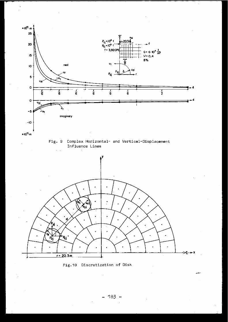
uziP2 . =, 103 t
=20.3 d=103 t 11111=
f = 3,92CPS 11111-"I'.- G . 6 . I04j11111= V= 0,4
*ern
25
1 5
1 0
-10
e10 3 m
Fig . 9 Complex Horizontal- and Vertical-Displacemen tInfluence Lines
Fig .10 Discretization of Dis k
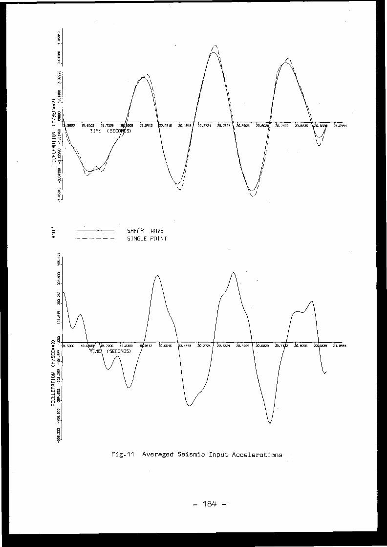
SHERR WAVE
SINGLE POINT
Fig-11 Averaged Seismic Input Acceleration s
- 184 -
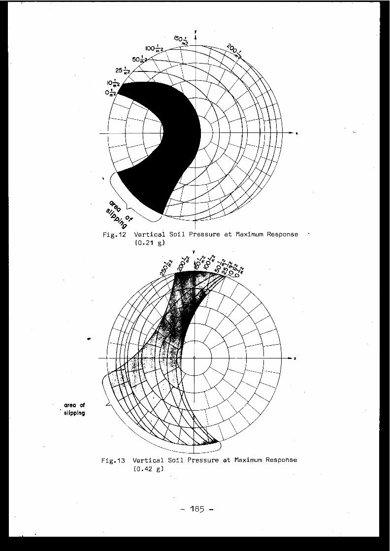
Fig .12 Vertical Soil Pressure at Maximum Respons e(0 .21 g)
Y
area of
slipping
•
Fig .13 Vertical Soil Pressure at Maximum Respons e
(0 .42 g)
- 185 -
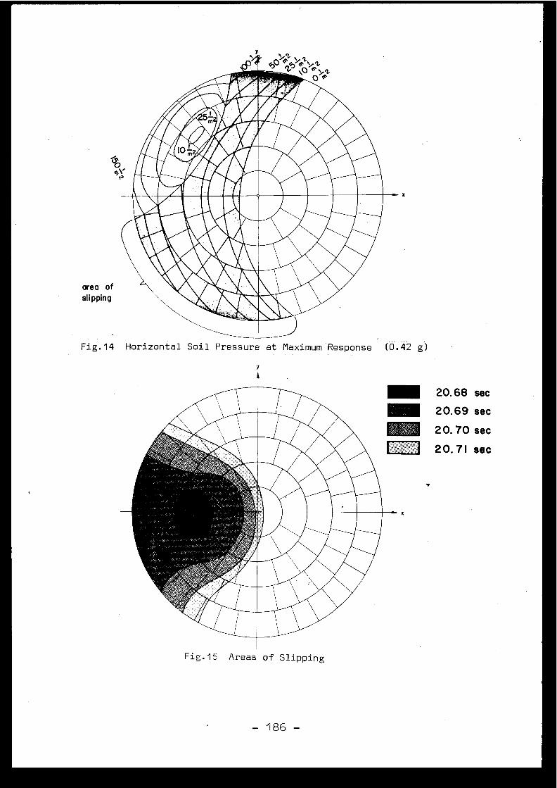
Fig .14 Horizontal Soil Pressure at Maximum Response (0 .42 g )
y
Fig .15 Areas of Slipping
20.68 sec
20.69 sec
20.70 sec
20 .71 sec
- 186 -
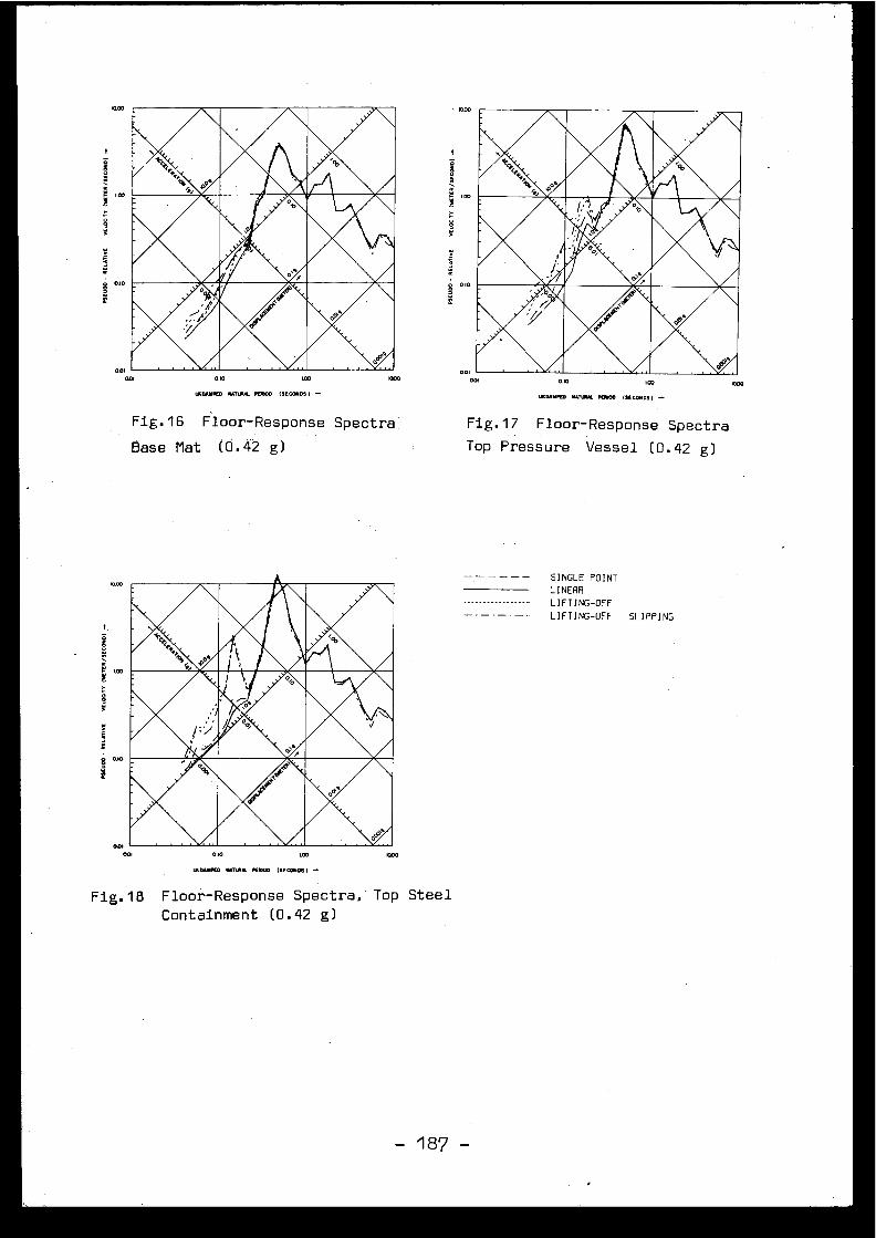
COO
.00
S 0 .) 0
S
00)
001
v.wrr-Am.k.A, .t‘n‘tmm6:'AldLA&A
100 0
IYD.MÆO NSTYI.L PEM00 (SECONDS) -
Fig .16 Floor-Response Spectra .
Base Mat (0 .42 g)
MR.k''14kAAnMI&
A.L.Ab&Af
i
0 .10
...FED M*TIAM. PESON (SECONDS) -
Fig .17 Floor-Response Spectr a
Top Pressure Vessel (0 .42 g )
O.IS10D
PrOIMM,MOMMAlikAdLAbhh.Ar
(Ou
IncoSINGLE POIN T
LINEA R
LIFTING-OF F
LIFTING-OFF
SLIPPIN G
I00
001
00) 000
ONO.Y.m MSTLOt POISON (SECONDS) -
Fig .18 Floor-Response Spectra, Top Stee l
Containment (0 .42 g )

Discussions
N.N. AMBRASEYS, United Kingdom
Dr . Wolf's contribution is one of the most interest -ing presented at this conference . Slab action, coupled withradiation and foundation yielding is one of the most importantparametres in earthquake design . Criteria which disregard thi stype of effect and insist on the elastic solution of geometri-cally complicated soil-structure configurations are unrealisti cand make a severe drain not only on the ressources, but als oon the patience of applicants for a permit to build a plant .
Figures 5 to 7 of my contribution in Session 2 showa three-dimensional representation of the effect of wave-lengthon the high-frequency portion of the response spectrum . We useda method almost identical to that employed by Dr . Wolf for th enon-slip, one-dimensional case . These figures show a drasti cdecrease in acceleration response of the slab at high frequen -cies .
I wonder whether the recent recordings from theearthquake of Ferndale of 7th June 1975 at the Humboldt BayPlant (i .e . 35 %g free-field acceleration, and 20 %g averagein the Plant, 100 metres away) do not confirm the importanc eof high-frequency energy loss at the interface of slab andfoundation ?
I am not clear whether in the paper just presente dby Mr . Wolf, radiation was taken into consideration for th efoundation material and bedrock . I understood that impedanc eof the structure with the foundation was taken care of . Butwhat about radiation between bedrock and foundation, which i san equally important factor ?
J .P . WOLF, Switzerland
The radiation damping is taken into considerationin the example and so a certain amount of internal materialdamping of the soil has been incorporated . This is basicallythe imaginary part of the influence functions .
D . COSTES, Franc e
Avez-vous considéré la combinaison des mouvement shorizontaux et verticaux du sol et l'effet correspondant su rle soulèvement ?
J .P . WOLF, Switzerland
The model is truly three-dimensional . The effectof uplift and slipping of the vertical motion is thus consi -dered . For the actual design of the nuclear power plan tLeibstadt, in addition, a vertical acceleration time historywas used in combination with a horizontal time history .
C . PLICHON, Franc e
Dans votre analyse non linéaire qui prend en compt ele basculement du radier, avez-vous pris en compte le poin-çonnement permanent qui résulte du fait de l ' augmentationimportante de la contrainte de compression ?
J .P . WOLF, Switzerland
The only non-linearity is introduced in the are aof contact : compressive normal stresses and correspondingshear stresses (friction) . The soil remains elastic everywher eelse (with the exception of hysteretic material damping) .
H . SHIBATA, Japan
What kind of waves do you use for analysis ? Fo rnon-linear problems like up-lifting is extremely depending oninput time history ?
J .P . WOLF, Switzerland
Artificial time histories, as described by Ruiz andPenzien .
H . SHIBATA, Japan
Do you find permanent deformation after the earth -quake in a particular portion of soil where the slip occurred ?How do you think about the design criteria, if you find theslip phenomenon in your analysis ?
J .P . WOLF, Switzerland
In this paper, only part of the foundation slips .In Ref . [6], slipping of the entire foundation mat is inves -tigated . It increases the factor of safety against standin gon edge (2 .6 versus 2 .3) .
[3 .3 1
DESIGN AND RESEARCH ASPECTS OF THE TREATMENT OF EARTH TREMOR EFFECT SON NUCLEAR POWER PLANT STRUCTURES AND COMPONENT S
H .J . Dowler, K . Fullard and I .C . SimpsonBerkeley Nuclear Laboratories ,Central Electricity Generating Board ,Berkeley, Gloucestershire, U .K .
Abstract :
The paper discusses nuclear power plant modelling in the context o fseismic analysis . Solution techniques are discussed and two distinc ttypes of problem in the soil-structure interaction area are considered .These are the modification of free field acceleration time historie scaused by the presence of the plant and base mat size effects i nconnection with frequency filtering . Finally our approach to the problemof soil amplification and layering is presented .
1 . Introduction
The designer needs loading data to apply to his particular piece o fequipment, building or component, or factors to apply to previousl yderived dynamic characteristics of his component . The former is suppliedas loading time histories and the latter as response spectra . In orderthat the appropriate set of floor time histories should be supplied, it isnecessary to take into account thé dynamic characteristics of th esupporting system of the component, from bed rock through building an dlarger components . A technique of modelling the load path is needed an dthis paper discusses our approach to the problem of developing such atechnique . Views on the appropriateness or otherwise of spectra lanâlysis are presented, together with the necessity for carrying ou tdirect solutions of the equations of motion .
The paper discusses our method of approach to the following tw odistinct types of problem in the general soil-structure interaction area :
(1) The modification of the free field earthquake acceleration-tim ehistory due to the large inertial forces of a nuclear power plant .
(2) The frequency filtering effect caused by the spatial dependenceof the acceleration-time history under the area of a rigid base mat, whe nthe wavelengths of seismic waves are less than or comparable to thedimensions of the base mat .
Finally, our approach to the problem of soil amplification and th emethods used in the determination of a surface acceleration time histor yfrom a given bedrock motion for a layered system is presented .
2, Structural Representation
We are in favour of using a model to represent the nuclear powe rplant which is as economical to set up as is consistent with ou rknowledge of all variables involved in seismic analysis . Soil represent-ation is dealt with later . As far as the building, equipment, piping, etc .is concerned, in carrying out preliminary analyses we intend treating th eoverall system as a series of masses linked by springs and rigid stalk swith subsystem dampers . The substructures will represent whole or partia lstructural features and the rigid stalks will be needed to link these .An obvious example of the use of the rigid stalk would be to join th ecentre of gravity of the base mat to the centroid of the base of th econtainment walls .
Obviously we could represent structures by two or three dimensiona lfinite element meshes and form mass and stiffness matrices in terms o fa limited number of degrees of freedom (Irons, 1965) . However, whenpreliminary analyses are carried out, not all geometry is necessaril yfixed and in any case seismic analyses are likely to change componen trestraints . For these reasons a simple model is justified . Certainsubstructures will be represented by a small number of lumped masses an ddetailed analyses performed later . The input for these detailed analyse swill come from the overall system analysis .
The input to the overall system is expected to be bedrockacceleration time histories . Thus more accurate base mat or floor time
- 191 -
histories will be obtained than would be the case if the free field tim ehistory were simply to be applied at the base mat . Aspects of soi lstructure interaction are considered later in this paper . From ourmass-spring-damper model we would hope to have time histories to apply t oeach support of a component or piping system . It would then be possible t ocarry out subsystem seismic analyses in as much detail or with as muc haccuracy as desired, using the time histories directly or via the respons espectrum technique . Phase effects are, however, ignored if response spectraare used and there are difficulties in deciding upon appropriate respons espectra with multi-supported systems . Naturally, it is recognised thattransient analyses are more expensive than response spectra analyses bu tthere is an element of unknown conservatism in establishing stress level susing the latter technique which we are not happy about . Comparativeanalyses on selected systems are needed to increase confidence .
It has already been stated that input to the overall system i sexpected to be time histories . Insufficient data is available to us in th eU .K . to allow a scaled design response spectra approach, as with the U .S .Regulatory Guides, which is peculiar to the U .K . Another CEGB paper(Mallard, Irving & Corkerton, 1975) deals with selection of appropriat etime histories .
Although a solution is more easily obtained using an orthogona ldamping matrix, since model methods may be used, the physical significanc eof such damping is far from clear . Since the damping in the soil an dstructure are different, even though accurate values are difficult t oobtain, it is our belief that it is necessary to use a direct iterativ emeans of solution for the equations of motion .
3 . Soil-structure interactio n
During surface motions caused by an earthquake, the inertia force sof large buildings resist the ground motion and modify the seismic wave slocally from their free field form . A free field acceleration-timehistory therefore has to be modified when a heavy structure is presen tbefore using this record as input for the structural analysis o fcomponents .
Several methods of analysis are available to deal with this effect .One well known, simplified method is to model the structure as a lumpedmass system connected to equivalent soil springs . (Jennings and Bielak ,1972) .
The advantage of this method is that soil constants can bedeveloped for embedded structures (Bielak, 1974) . The theoreticaldisadvantage is that the elements of the compliance matrix are frequenc ydependent and their values often have to be approximated by th efundamental frequency . Such problems can be circumvented by the use ofLaplace or Fourier transforms . (Lee & Wesley, 1971, 1972) .
An alternative method, which essentially involves the solution of th eclassical Lamb problem, has been developed by Scavuzzo, Raft . & Bailey(1971, 1972) . Here the response of a half space to a surface applied load(inertia force of the structure) . is calculated and superimposed onto thefree field seismic motions in order to obtain the modified acceleratio ntime history . This type of approach has been used at B .N .L . to analyz ethe situation where adjacent structures interact through the soil durin g
earthquake excitation . The method has the drawback that it cannot dea l
- 192 -
with embedded structures and that the extension of the soil model from a nidealised half space to a multilayered system makes the solution of . theproblem very complex . Our first level approach to the soil structur einteraction problem has been to determine site dependent ground surfac eacceleration time histories by the methods described in section (4) and t ouse them as input into the above soil-structure interaction model .Although this method is only very approximate since the interaction mode ltakes no account of soil layering, it is felt that such simplified model sare essential to gain an understanding of the overall problem and establis htrends in the interaction effect . Such models will be used to check th eresults of a more complicated finite element analysis with energ yabsorbing boundaries and the impedance function approach described by Luc oand Westmann (1971, 1972), Luco (1974) .
At present, we are also considering methods to deal with frequenc yfiltering in the case of horizontally travelling seismic waves o fwavelengths less than or comparable to the dimensions of a rigid base mat .This type of effect has been discussed by Scanlan (1975) .
4 . Soil amplification
During an earthquake, ground movement and the resulting damage t ostructures are strongly influenced by local geological conditions at asite . Layers of soft soil overlying bedrock will create a strong boundar ybetween materials of greatly different properties . Seismic waves emergingfrom bedrock set up an interference pattern of waves within the surfac elayers . The layered system will resonate with frequencies of the bedrockmotion that are close to its natural frequencies and amplification o fbedrock motion will result . Hence, very high maximum accelerations ma yresult at the surface of a layered system for a given acceleration-tim ehistory applied at bedrock level, assuming an elastic model .
On the other hand, soft soils have relatively low strength andyielding is likely to take place during a strong earthquake . Thi syielding will tend to suppress motion at the surface of the layered systemand place an upper bound on the maximum accelerations that occur at th esurface . Hence, amplification effects will occur if the stresses induce din the soil layers are well below the minimum strength of the soi l(i .e . for weak bedrock seismic motions or strong soil layers) Suppressio neffects will take place when very strong seismic motions occur in th ebedrock or if the soil deposits are very soft and cannot transmi taccelerations above a certain amplitude to the surface .
In order to determine site dependent acceleration-time historiesfor an assumed bedrock motion a series of computer programs are bein gdeveloped at B .N .L ., which treat the problem as a one dimensional wavepropagation effect . It is assumed that the seismic wave train is normall yincident on a perfectly horizontal layered system with no spatia ldependence in the horizontal directions . For non vertical incidenc ethe Thomson-Haskell matrix method can be used . For the case of perfectlyelastic layers with radiation damping ray tracing methods (Baranov an dKunetz, 1960) are found to be the most efficient . For viscoelasti cdamping (Voigt or standard linear model) in the layering system wit hbedrock radiation, solutions of the equations of motion have been foun dby Laplace transform techniques and residue calculus or alternatively b ycontinuous modal analysis . Finally lumped mass modelling of th e
- 193 -

equations of motion is being .used to solve the full elastoplastic-viscou smodel . When the problem is fully understood one dimensionally it is hope dto develop two dimensional programs using finite elements or lumped mas smodels . These programs will at the same time incorporate th esoil-structure interaction problem .
Conclusion s
1. We are in favour of simplified representation of power plant b ymass-spring-damper models for studying the behaviour of the overal lsystem from bedrock up .
2. We believe it is more appropriate in view of damping difference sbetween soil and structure to use direct solution techniques i nsolving the equations of motion .
3. It is considered to be vital to develop one dimensional models fo rsoil-structure interaction and soil amplification to increas eunderstanding of the effects involved and to validate more comple xtwo dimensional continuum or finite element models .
Acknowledgmen t
This paper is published by permission of the Central Electricit yGenerating Board .
Reference s
Baranov, V ., Kunetz, G ., (1960), "Film synthetique avec reflexion smultiples theorie et calcul pratique", Geophys .Prosp ., 7, p .315-25 .
Bielak, J ., (1974), "Dynamic behaviour of structures with embedde dfoundations", Universidad Nacional Autonoma de Mexico, Report E8 .
Irons, B ., 1965, "Structural Eigenvalue Problems : Elimination of UnwantedVariables", AIAA J .3, 961-962 .
Jennings, P .C ., Bielak, J ., (1973) "Dynamics of building-soil interaction" ,Bull . Seis . Soc . Am ., 63, 9-48 .
Lee, T .H ., Wesley, D .A ., (1971), "Soil-foundation interaction of reacto rstructure subject to seismic excitation", 1st Int . Conf . on SMiRT, Berlin ,Germany, paper K3/5 .
Lee, T .H ., Wesley, D .A ., (1972), "Soil-structure interaction of nuclea rreactor structure considering through soil coupling between adjacen tstructures" , Gulf GA-A-12356 Gulf General Atomic Co ., San Diego ,California .
Luco, J .E . & Westmann, R .A ., (1971), "Dynamic response of circula rfootings", J .Eng .Mech .Div ., ASCE 97 (EM5), 1381-95 .
Luco, J .E . & Westmann, R .A ., (1972), "Dynamic response of a rigi dfooting bonded to an elastic half space", J .Appl .Mech . ASME 39, 527-534 .
Luco, J .E . (1974), " Impedance functions for a rigid foundation on alayered medium", Nucl .Eng .Des ., 31, 204-217 .
Mallard, D .J ., Irving, J . and Corkerton, P .A ., 1975, "Assessment o fseismic design criteria for nuclear power stations in England and Wales" ,CSNI Specialist Meeting on Anti-Seismic Design of Nuclear Installations .
Scanlan, R .H . (1975), "Seismic wave effects on soil-structur einteraction" , 3rd Int .Conf . on SMiRT, London, paper K2/1 .
Scavuzzo, R .J ., Raftopoulos, D .D ., Bailey, J .L . (1971), "Lateral structur einteraction with seismic waves", J .Appl .Mech ., 38, 125-134 .
Scavuzzo, R .J ., Raftopoulos, D .D ., Bailey, J .L ., (1972), "Lateralstructure-foundation interaction of structures with base masses", Bull .Seis .Soc .Am ., 62, 453-470 .

Discussion s
J .V . PARKER, United Kingdom
What method or methods are you using for the direc tsolution of the equations of motion ?
K . FULLARD, United Kingdom
We are not committed to any particular method . Weexpect to use well-known techniques and have no intention atthe present time of doing any research into improvements .
[3 .4]
WAVE PROPAGATION IN SOLIDS
J.F. VernetEcole Polytechnique - Ecole Nationale Supérieure des Mines de Pari s
Laboratoire de Mécanique des Solide sEquipe de Recherche Associée au C .N.R.S .
Résumé :
Les tremblements de terre sont des propagations d'ondes dan sl'écorce terrestre . Cette dernière peut être considérée comme un solid eélastique linéaire ou non linéaire, ou viscoélastique, ou plastique . Dansles solides isotropes homogènes, il y a une onde longitudinale et une ond etransversale . A la surface d'un semi-massif, il y a des ondes de Rayleigh .A l'interface de deux semi-massifs, cette onde est appelée onde de Stonele yDans une couche mince déposée sur un substrat, il y a des ondes de Love .
On peut encore considérer le cas des solides périodiques ,(cristaux), des solides granuleux, des milieux continus généralisés, e tdes milieux aléatoires .
Abstract :
Earthquakes are wave propagations in the terrestrial crust .This last can be considered as a linear or non-linear elastic solid, o ras visco-elastic or plastic . In homogeneous isotropic solids there is alongitudinal P wave and a traverse S wave . At the surface of a semi-infinite substance there are Rayleigh's waves . At the interface of twosemi-infinite substances, this wave is cabled Stoneley's wave . In a thinlayer deposited on a substrate, one has Love's waves .
One can also consider the case of periodic solids (crystals) ,granular solids, generalized continuous media and random media .
The object of the present report being very extensive, tim elimitation restricts it to a nomencL ure and a bibliography .
Earthquakes can be considered as wave propagations in the ter-restrial crust . The historical background of the study of these waves ca nbe made using the book of E . Rothé, Directeur de l'Institut de Physique duGlobe (1) .
The waves present themselves in mathematical form as sinusoï-dal waves or as pulses (Dirac) or steps (Heaviside) ; in physical form astransient waves more or less irregular .
The solids in which these waves propagate can be defined as bodieswhich, different from liquids and gases, do not take exactly the form ofthe container in which they are held . Thus a sand dune is a solid . Thetransition between solids and liquids is sometimes difficult to grasp . Itcan be due to a variation of temperature, or at fixed temperature, to a
slow evolution (as cristallisation of honey), or to application of vibra-tion (as vibration of newly made concrete), or to application of very highpressure as in the plastification of rock under triaxial constraint .
Restricting oneself to solids, they can undergo elastic, visco-elastic or plastic deformations . The two first types of deformation can beeither linear or non linear according to the constitutive equations and theextent of the deformation . Linear elastic deformations have been studied inthe following cases :
1.- Homogeneous_ solids .
One finds that there are two elastic coefficients, the coeffi-cients of Lamé :
for dilatation
µ for shearing .
One uses sometimes in place of these :
Young's modulus Eand Poisson's coefficien t
One can consult here the course of Mandel, Professeur à 1'EcolePolytechnique et à l'Ecole des Mines (2) .
2.- Periodic solids .
These are crystals . One obtains a more or less large number o fcoefficients of elasticity depending on the syrmetries of the crystal . Forwave propagation in crystals, one may consult the book of Brillouin andParodi (3) .
3.- Granular solids .-------------
- 198 -
One can consult the fondamental article of Biot (4) and White' sbook (5) .
4.-Generalized continuous media .
One can consult Kroner's book (6) .
5.-Random media .
One can consult the articles of J .F . Vernet (7) and (8) .
After elastic deformations, one can study linear viscoélasti cdeformations, for which a variational principle has been established b yGurtin . This principle, as well as a bibliography, are reported in an ar -ticle by J .F . Vernet (9) .
After linear deformations, one can approach the essentiallynon linear phenomena of plasticity with the fondamental article ofJ. Mandel in Journal de Mécanique (10) .
The bibliography of the constitutive equations having alread yintroduced us to the study of waves,v now examine them in more detail . Werecommend specially Dieulesaint's book (11) .
In the case of a simple homogeneous isotropic linear elasticsolid infinite in three dimensions, one finds that there are two "acous -tiâ" waves called respectively longitudinal and transverse . In a genera-lisation of a Poisson's theorem, Mandel (1962) explains that a longitudi -nal wave corresponds to an irrotational displacement involving variation sof volume (and temperature), whereas the transverse wave corresponds to arotational displacement without variation of volume (or temperature) .
Neglectinng theeffect of temperature, the velocity of the lon -gitudinal wave is f74 -r tµ)fio , which in
Sial corresponds approxima-tely to 5000m/s . The velocity of the transverse wave is rztA./fo , whichcorresponds approximately to 3000 m/s .
In ease when the solid is non longer infinite, but has limits ,the propagation velocity is modified, because the waves reflect at th eboundaries, transforming themselves into each other . For example in therise of a thin and long bar, Kolsky shows that the longitudinal wave' svelocity is reduced to ET . This comes Lpvm the fact that the longi -tudinally compressed bar can expand freely in the transverse sense (due t oPoisson's coefficient), while this transverse expansion cannot take plac ein an infinite medium. On the contrary, torsion waves in the bar have thesame velocity as transverse waves in an infinite medium. Moreover in thecase of a bar, one can have flexural waves, of which the velociist nolonger independant of the wave length . One says
in this case ere i sdispersion .
At the surface of a semi-infinite medium, one can have waveswhich propagate like waves on the surface of the sea (however without th einfluence of gravity) . They carry the name of Rayleigh, who discoveredthem in 1885 . Like the sea swell, their amplitude diminishes exponentiallywhen the depth increases in such a manner that they become practically un -detectable at a depth which is twice the wave length. Their velocity is
- 199 -
smaller than that of the transverse waves .
A figure in Robinson's book (13) shows the successive arrivalin Sweden of longitudinal, transverse and Rayleigh waves produced by a nearthquake of which the epicenter was in Greece .
If the material is limited by two parallel planes separate dby a distance of the order of the wave length, one obtains Lamb waves ,symmetric or antisymmetric .
At the interface of two semi-infinite solids with differen telastic properties a Stoneley wave can propagate, whose amplitude decrease son both sides of the interface .
If the medium is composed of a thin layer deposited on a sub-strate the surface waves are called Love waves . They are transverse, andonly exist if the transverse speed in the thin layer is smaller than thatin the substrate .
We note that Rayleigh, Love and Stoneley discovered the wavesthat carry their names during the study of earthquakes .
Waves in multilayered media are studied in Ewing's book (14) .Another useful book is that of Redwood (15) .
To be complete, one should note-interactions with gravitywaves : maritime, terrestrial and atmospheric tides (ground-swell or tsu -namis), and with elastic waves in oceans, atmosphere, and in the partiallyliquid Nife core .
When an earthquake acts on a structure, it excites interna lvibrations . A structure can be analysed in a certain number of degrees o ffreedom, or can be considered as an elastic continuum . In the two casesone can determine the normal modes and frequencies by diagonalising thevibration matrix . From this one can deduce the effect on the structure o ftransient waves, which is not difficult if one stays in the linear domain .One can note in this context Barkan's book (16) .
After the case of an elastic solid, let us consider the cas eof an elastic-plastic solid, according to Mandel (10) .
Solids can go from an elastic state to a plastic state, onthe inverse, across a mobile surface of discontinuity . There are four pos -sible modes :
Elastic -4 elastic (elastic wave)Plastic -4 plastic (plastic wave)Plastic elastic (unloading boundary )Elastic --* plastic (loading boundary) .
The arrow indicates the sense of the transition undergone bythe element of the material .
One has a shock wave if the speed 1 is discontinuous . Onehas an ordinary wave if the acceleration
Kis discontinuous .
For an elastic wave, there are for all directions of the wavenormal, three mutually orthogonal polarisation directions, and three cor -responding velocities, to each of which one can assign an order numberwhich is greater for the smaller velocity .
For an ordinary plastic wave, there are for all directions
- 200 -
of the wave normal three mutually orthogonal polarisation directions as i nelasticity . Each velocity is inferior to the elastic velocity of the sam eorder number, but superior to the elastic velocity of the following orde rnumbers .
In an isotropic medium, one of these polarisation directions is ltransverse, and the corresponding velocity is that of transverse elasti cwaves . The others, in general oblique to the wave, have a velocity, thefirst contained between those of the transverse elastic wave and the lo n-gitudinal elastic wave, and the second less than that of the transvers eelastic wave .
The velocity of an unloading boundary is contained in one o fthe intervals between the velocity of a plastic wave and of an elasti cwave of the same order number . The possible velocities for a loading boun-dary belong to intervals which are complementary to the preceding ones .
In a three dimensional solid medium stable plastic shockwavescan exist, that is to say which do not immediately diffuse into ordinar ywaves . As in the case of gases, the conductivity or the viscosity or bothnecessarily intervene in the interior of the shock wave . If one does notgo into the detailed analysis of deformations, one can only study longitu -dinal waves, to which one extends the classical theory of Hugoniot, o rgnxüi-transverse waves which in the case of small deformations can b etreated like transverse waves .
This terminates our analysis of plastic waves .
- 201 -
BIBLIOGRAPJY4
(1) ROTHE E . - Les méthodes de prospection du sous-sol .(Troisième partie-Méthode seismique) . Paris, Gauthier-Villars, 1930, (bibliothè-que du Laboratoire de Mécanique des Solides de 1'Ecole Polytechnique, Palaiseau, n°386) .
(2) MANDEL J . - Cours de Mécanique des Milieux Continus . Paris ,Gauthier-Villars, 1966 .
(3) BRILLOUIN & PARODI - Propagation des ondes dans les milieux périodi-ques . Paris, Masson, 1956 .
(4) BIOT M.A. - Theory of elastic waves in a fluid saturated porou ssolid . J . of Acoust . Soc . Amer ., 28, n°2, pp . 168-191, 1956 .
(5) WHITE J .E . - Seismic waves : radiation, transmission and attenuation.New-York, Mc Graw Hill, 1965 .
(6) KRONER E . - Mechanics of generalized continua .I .U .T .A .M. Symposium Stuttgart, 1967, Berlin, Springer-Verlag .
(7) VERNET J .F . - Ondes acoustiques dans un guide aléatoire .Int . J . Solids & Structures, 1974, vol . 10, pp . 821-833 .
(8) VERNET J .F . - Produits de matrices de transferts aléatoires .1975, soumis à "Advances in Applied Probability" .
(9) VERNET J .F . - Prppagation des ondes dans un milieu périodique .Industrie Minérale, numéro spécial de la Mécanique des Roches ,juillet 1973 .
(10) MANDEL J . - Ondes plastiques dans un milieu indéfini à trois dimen-sions . Journal de Mécanique, Gauthier-Villars, Paris, vol .I ,n°1, mars 1962 .
(11) DIEULESAINI' E . & ROYER D. - Ondes élastiques dans les solides .Paris, Masson, 1974 .
(12) KOLSKY H . - Stress waves in solids . New-York, Dover, 1963 .
(13) ROBINSON E .A . - Statistical communication and detection with specia lreference to Digital Data Processing of Radar and Seismic Sig-nals . London, Griffin, 1967 .
(14) EWING, JARDEI'SKY, Press - Elastic waves in layered media. New-York ,Mc Graw Hill, 1957 .
(15) REDWOOD M . - Mechanical waveguides . Pergampn, 1960 .
(16) BARKAN - Dynamics of bases and foundations . Mc Graw Hill, 1962 .
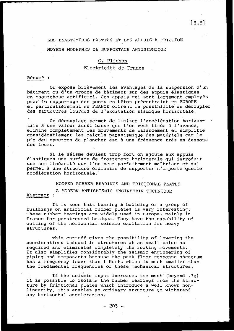
[3 .5 ]
LES ELASTOMERES FRETTES ET LES APPUIS A FRICTIO N
MOYENS MODERNES DE SUPPORTAGE ANTISISPMIQUE
C . Plichon
Electricité de France
Résumé :
On expose brièvement les avantages de la suspension d'u nbâtiment ou d'un groupe de bâtiment sur des appuis élastique sen caoutchouc artificiel . Ces appuis qui sont largement employé spour le supportage des ponts en béton précontraint en EUROP Eet particulièrement en FRANCE offrent la possibilité de découple rdes structures lourdes de l'excitation sismique horizontale .
Ce découplage permet de limiter l'accélération horizon -tale à une valeur aussi basse que l'on veut fixée â l'avance ,élimine complétement les mouvements de balancement et simplifi econsidérablement les calculs parasismique des matériels car l epic des spectres de plancher est à une fréquence très en dessou sdes leurs .
Si le séisme devient trop fort on ajoute aux appui sélastiques une surface de frottement horizontale qui introdui tune non linéarité que l'on peut parfaitement maîtriser et qu ipermet à une structure ordinaire de supporter n'importe quell eaccélération horizontale .
HOOPED RUBBER BEARINGS AND FRICTIONAL PLATE S
A MODERN ANTISEISMIC ENGINEERIN TECHNIQUEAbstract :
It is seen that bearing a building or a group o fbuildings on artificial rubber plates is very interesting .These rubber bearings are widely used in Europe, mainly i nFrance for prestressed bridges . They have the capability o fcutting of the horizontal seismic excitation for heavystructures .
This cut-off gives the possibility of lowering theaccelerations induced in structures at as small value a srequired and eliminates completely the rocking movements .It also simplifies considerably the seismic engineering o fpiping and components because the peak floor response spectru mhas a frequency lower than 1 Hertz which is much smaller tha nthe fondamental frequencies of these mechanical structures .
If the seismic input increases too much (beyond .3g )it . is possible to isolate the rubber bearings from the struc-ture by frictional plates which introduce a well known non -linearity . This enables an ordinary structure to withstandany horizontal acceleration .
- 203 -
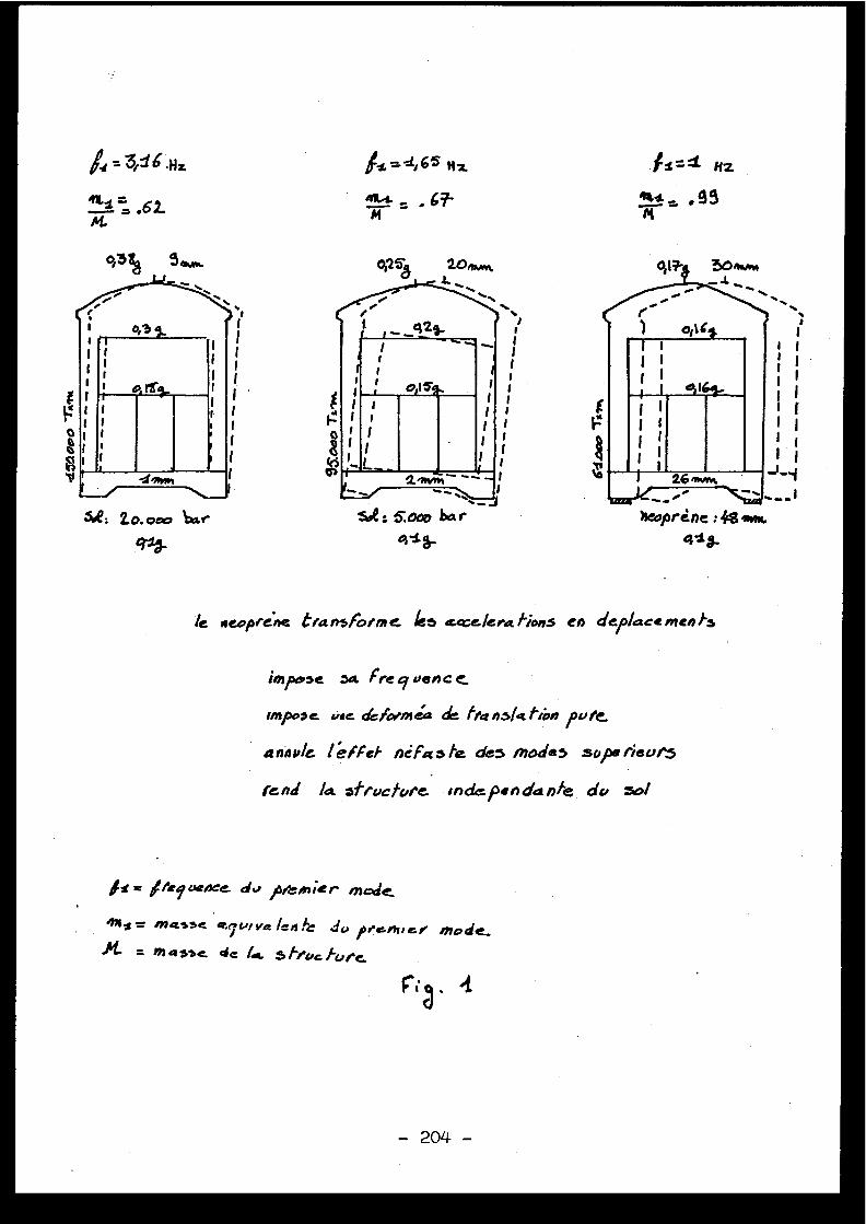
/e Aeoprege t/a nsfOlnl e %5 £ o e /epa. /iol5 CA dep/ace meld's
impose aa. fre o~ ven c e
rmpooe, v.e. dcfc?mea de tt4 qS /a than po t&
a nnv/e l éf ej' ncfa s fe de3 modes sops rieur5
fend /a *fracture 'nd€pendanfe da
~s= //efuenee d3 / Veinier made
Allo_ m4SSc a.epviye !'_ do ,''amie 3 mode-= mQSSt de fag. S/ruc fore.
=AO is m
mi-,. _ .67-m
.11=4 HZ
tes _ ,99M
2o. oeso ba r
q3
- 204 -
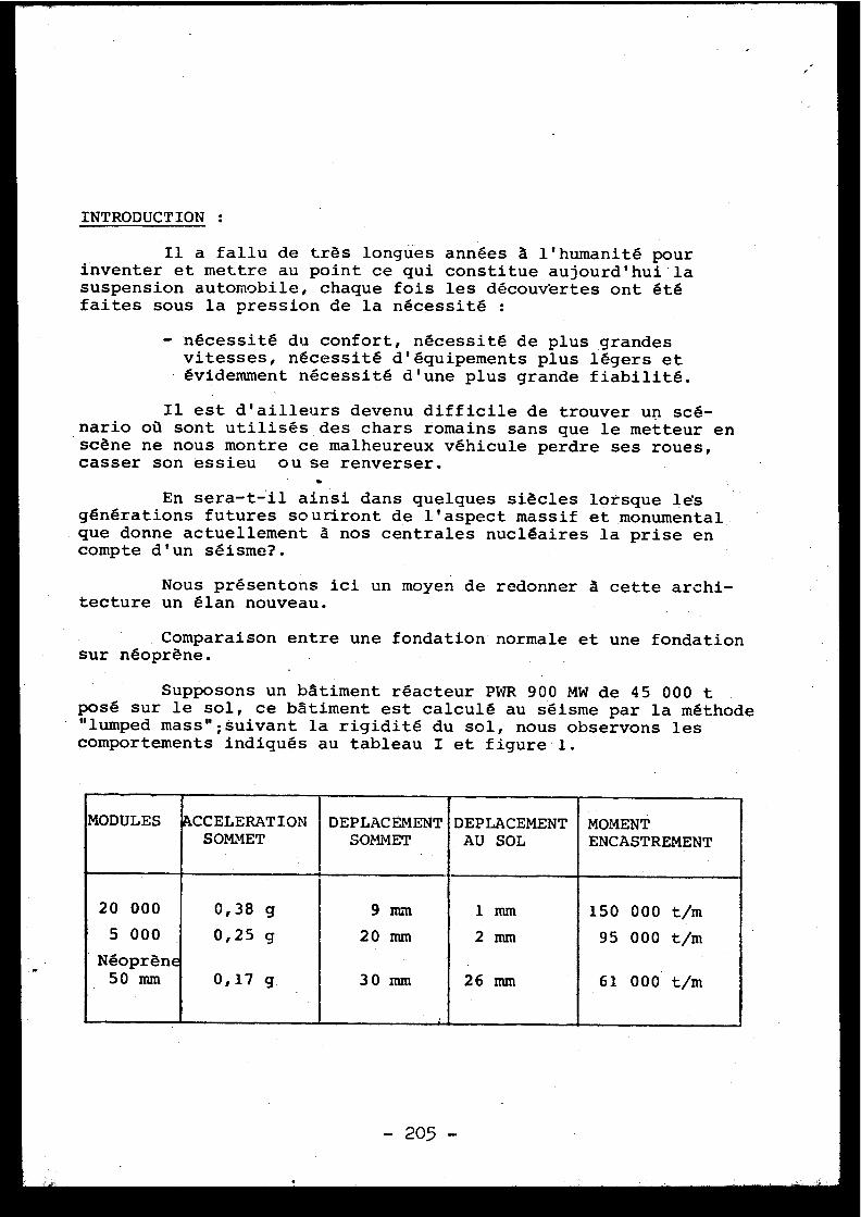
INTRODUCTION :
Il a fallu de très longues années à l'humanité pou rinventer et mettre au point ce qui constitue aujourd'hui l asuspension automobile, chaque fois les découvertes ont ét éfaites sous la pression de la nécessité :
- nécessité du confort, nécessité de plus grande svitesses, nécessité d'équipements plus légers e tévidemment nécessité d'une plus grande fiabilité .
Il est d'ailleurs devenu difficile de trouver un scé -nario où sont utilisés des chars romains sans que le metteur e nscène ne nous montre ce malheureux véhicule perdre ses roues ,casser son essieu ou se renverser .
En sera-t-il ainsi dans quelques siècles lorsque lesgénérations futures souriront de l'aspect massif et monumental .que donne actuellement à nos centrales nucléaires la prise encompte d'un séisme? .
Nous présentons ici un moyen de redonner à cette archi-tecture un élan. nouveau .
Comparaison entre une fondation normale et une fondatio nsur néoprène .
Supposons un bâtiment réacteur PWR 900 MW de 45 000 tposé sur le sol, ce bâtiment est calculé au séisme par la méthode"lumped mass ;suivant la rigidité du sol, nous observons le scomportements indiqués au tableau I et figure 1 .
MODULES ACCELERATIONSOMMET
DEPLACEMENTSOMMET
DEPLACEMENT MOMENTENCASTREMENTAU SOL
20 00 0
5 000
Néoprène
0,3 8
0,2 5
0,17
g
g
g .
9 mm
20 mm
30 mm
1
2
26
mm
mm
mm
15 0
95
61
000
00 0
000
t/m
t/m .
t/m50 mm
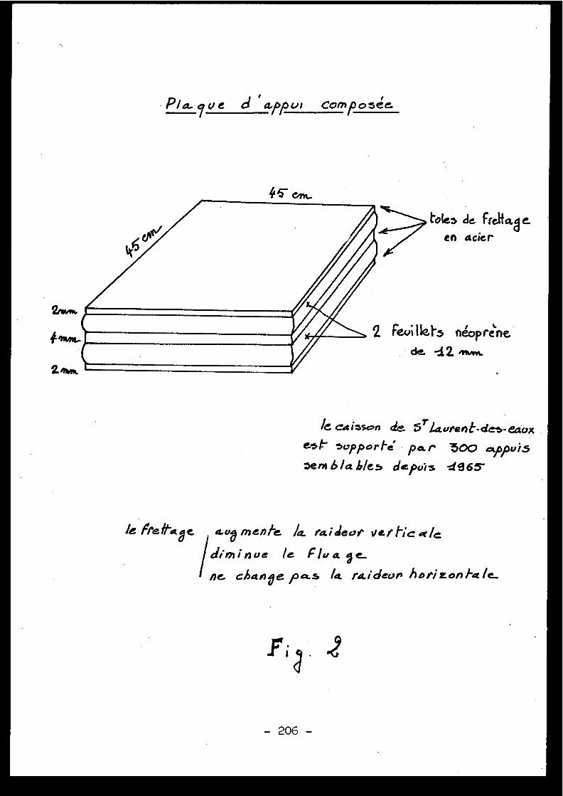
9ve d ' a pu1 composé e
~C caisson de. $Tlccureht-dc:s-ea.est- svppor/e par 300 cippui5sera b/a bleb depo'is X965
le Fre fl-aa e a-ov men/-e.
deaf Ilef tic ale
diminue le Flora fie..
ne change pa.s la raidean horizonhale_
- 206 -
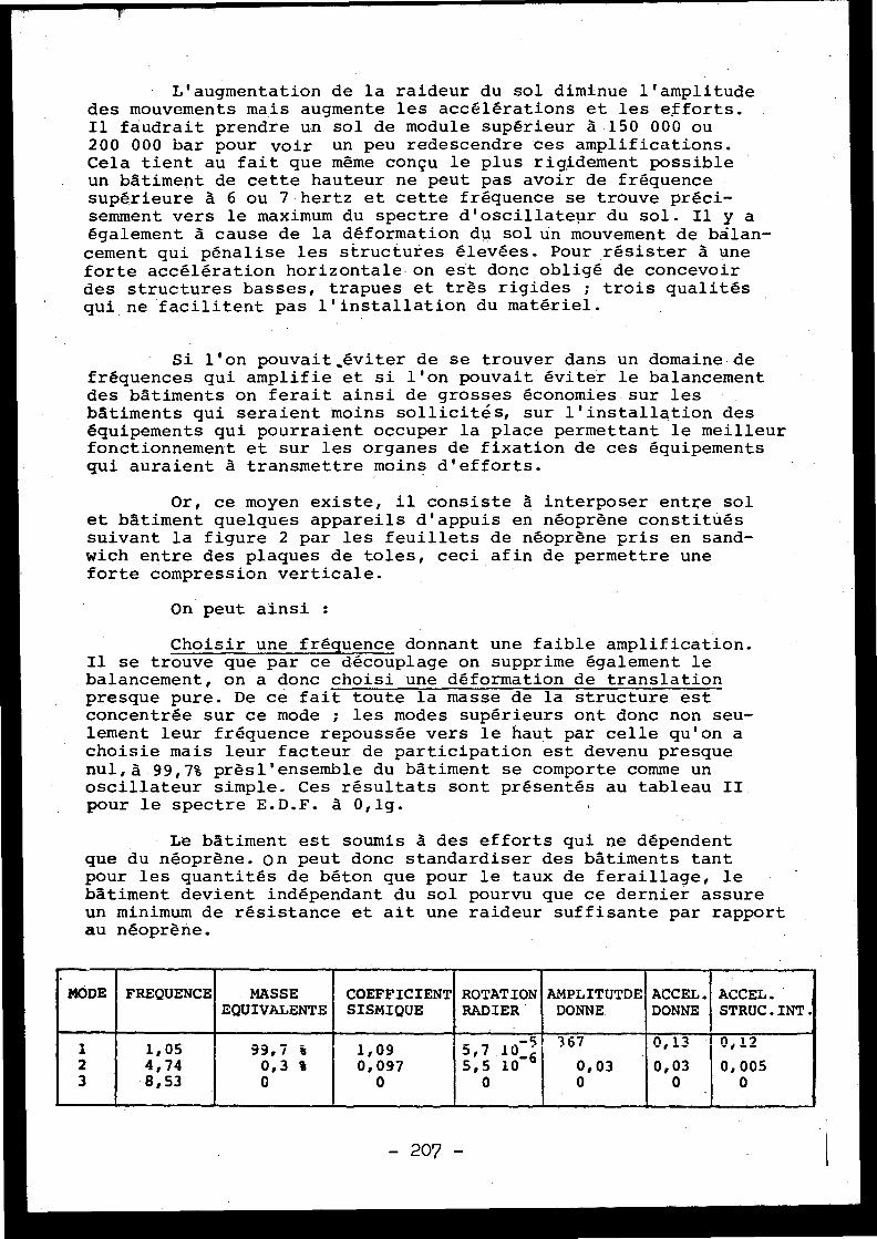
L'augmentation de la raideur du sol diminue l'amplitud edes mouvements mais augmente les accélérations et les efforts .Il faudrait prendre un sol de module supérieur à 150 000 o u200 000 bar pour voir un peu redescendre ces amplifications .Cela tient au fait que même conçu le plus rigidement possibl eun bâtiment de cette hauteur ne peut pas avoir de fréquenc esupérieure à 6 ou 7 hertz et cette fréquence se trouve préci-semment vers le maximum du spectre d'oscillateur du sol . Il y aégalement à cause de la déformation du sol un mouvement de balan-cement qui pénalise les structurés élevées . Pour résister à un eforte accélération horizontale on est donc obligé de concevoi rdes structures basses, trapues et très rigides ; trois qualitésqui ne facilitent pas l'installation du matériel .
Si l'on pouvait éviter de se trouver dans un domaine d efréquences qui amplifie et si l'on pouvait éviter le balancemen tdes bâtiments on ferait ainsi de grosses économies sur le sbâtiments qui seraient moins sollicités, sur l'installation de séquipements qui pourraient occuper la place permettant le meilleu rfonctionnement et sur les organes de fixation de ces équipement squi auraient à transmettre moins d'efforts .
Or, ce moyen existe, il consiste à interposer entre so let bâtiment quelques appareils d'appuis en néoprène constitué ssuivant la figure 2 par les feuillets de néoprène pris en sand-wich entre des plaques de toles, ceci afin de permettre un eforte compression verticale .
On peut ainsi :
Choisir une fréquence donnant une faible amplification .Il se trouve que par ce découplage on supprime également l ebalancement, on a donc choisi une déformation de translationpresque pure . De ce fait toute la masse de la structure es tconcentrée sur ce mode ; les modes supérieurs ont donc non seu-lement leur fréquence repoussée vers le haut par celle qu'on achoisie mais leur facteur de participation est devenu presqu enul,à 99,7% prèsl'ensemble du bâtiment se comporte comme u noscillateur simple . Ces résultats sont présentés au tableau I Ipour le spectre E .D .F . à 0,1g .
Le bâtiment est soumis à des efforts qui ne dépenden tque du néoprène . on peut donc standardiser des bâtiments tan tpour les quantités de béton que pour le taux de feraillage, l ebâtiment devient indépendant du sol pourvu que ce dernier assureun minimum de résistance et ait une raideur suffisante par rappor tau néoprène .
MODE FREQUENCE MASSEEQUIVALENTE
COEFFICIENTSISMIQUE
ROTATIONRADIER
AMPLITUTDEDONNE .
ACCEL .DONNE
ACCEL .STRUC .INT .
-5 367 10,13 1 21 1,05 99,7 % 1,09 5,7
10_"62 4,74 0,3 % 0,097 5,5 10 0,03 0,03 0,00 5
3 8, 53 0 0 0 0 0 0
- 207 -
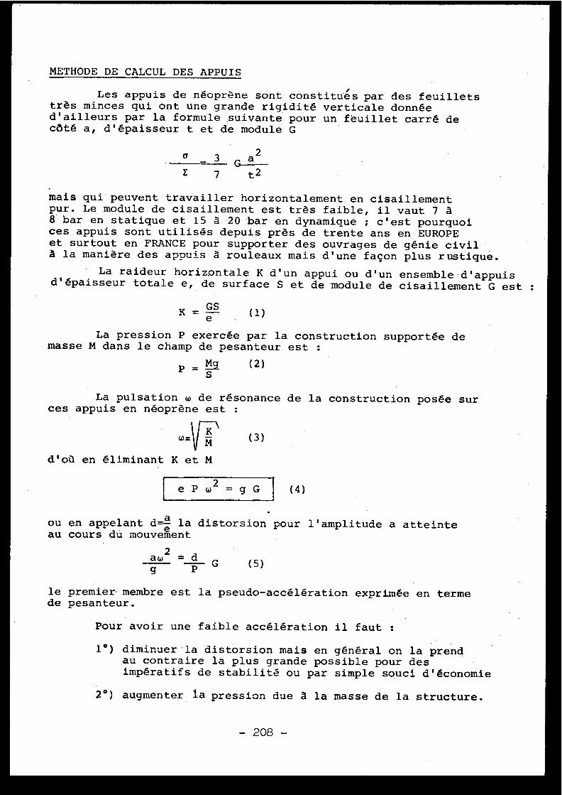
METHODE DECALCULDESAPPUI S
Les appuis de néoprène sont constitués par des feuillet strès minces qui ont une grande rigidité verticale donné ed'ailleurs par la formule suivante pour un feuillet carré d ecôté a, d'épaisseur t et de module G
a _ 3 G a2E
7
t2
mais qui peuvent travailler horizontalement en cisaillemen tpur . Le module de cisaillement est très faible, il vaut 7 à8 bar en statique et 15 à 20 bar en dynamique ; c'est pourquoices appuis sont utilisés depuis près de trente ans en EUROPEet surtout en FRANCE pour supporter des ouvrages de génie civi là la manière des appuis à rouleaux mais d'une façon plus rustique .
La raideur horizontale K d'un appui ou d'un ensemble d'appui sd ' épaisseur totale e, de surface S et de module de cisaillement G est :
La pression P exercée par la construction supportée d emasse M dans le champ de pesanteur est :
P = la
(2 )La pulsation w de résonance de la construction posée su r
ces appuis en néoprène est :
S
waK \M (3 )
d'où en éliminant K et M
e P w 2 = g G
ou en appelant d=e la distorsion pour l'amplitude a atteint eau cours du mouvemen t
le premier membre est la pseudo-accélération exprimée en termede pesanteur .
Pour avoir une faible accélération il faut :
1°) diminuer la distorsion mais en général on la prendau contraire la plus grande possible pour desimpératifs de stabilité ou par simple souci d'économie
2°) augmenter la pression due à la masse de la structure .
- 208 -
(4 )
aw l = dg P G
(5)

Pour dimensionner les appuis, il suffit donc sur la fig . 3
1°) de se fixer une pseudo-accélération à ne pas dépasse rdans la structure par exemple 0,2 g
2°) chercher l'intersection de cette ligne avec l espectre à 5% choisi, on trouve ainsi la fréquenc ed'oscillation et,pour une distorsion donnée de 1par exemple,l'épaisseur de néoprène nécessaire .
TABLEAU II I
1 hertz et 5 cm pour le spectre E .D .F . A (0,2g )0,65
" 12 cm Parkfield à (0,6g )0,4
" 30 cm O
Elcentro à (0,33g )0,2 120 cm USAEC à
(0,6g )
soi t
Ayant choisi la distorsion l'application de la formul e(5) nous fourni la pression soit en prenant G = 20 ba r
P = 022 = 100 bar
puis connaissant la masse : M = 45 000 tonnes la formule (2 )donne la surface totale
s= ! = 45106x10=45m2
P
100 105
que l'on peut,pcr exemple, répartir en 45 appuis de 1 m2 ou 9 0appuis de 0,5 m ou 180 appuis de 0,25 m 2 au choix tant que l ahauteur totale de néoprène de chaque appuis reste inférieur eà 5 fois la largeur de l'appui, limite au delà de laquelle il ya risque de déversement latéral .(Cf . documentation stup) .
On conçoit donc que cette solution ait des limites ca ril deviendrait difficile d'adapter une structure de cetteimportance à un nombre d'appuis trop réduits sans parler del'inconvénient que constitue une fréquence trop basse en égar dà l'action du vent , au freinage d'un véhicule lourd ou d'u npont roulant .
Du simple point de vue des dimensions en reprenant le scas du tableau III, il faudrait que la largeur des appuis asoit supérieure à :
25 cm pour le spectre E .D .F . A 0,2g60 cm ParkfieldParkfield à 0,6g
150 cm Elcentro à 0,3g60.0 cm USAEC à 0,6g
* 1 bar = 1 kg/ . -cm2
-209 -209 -
si
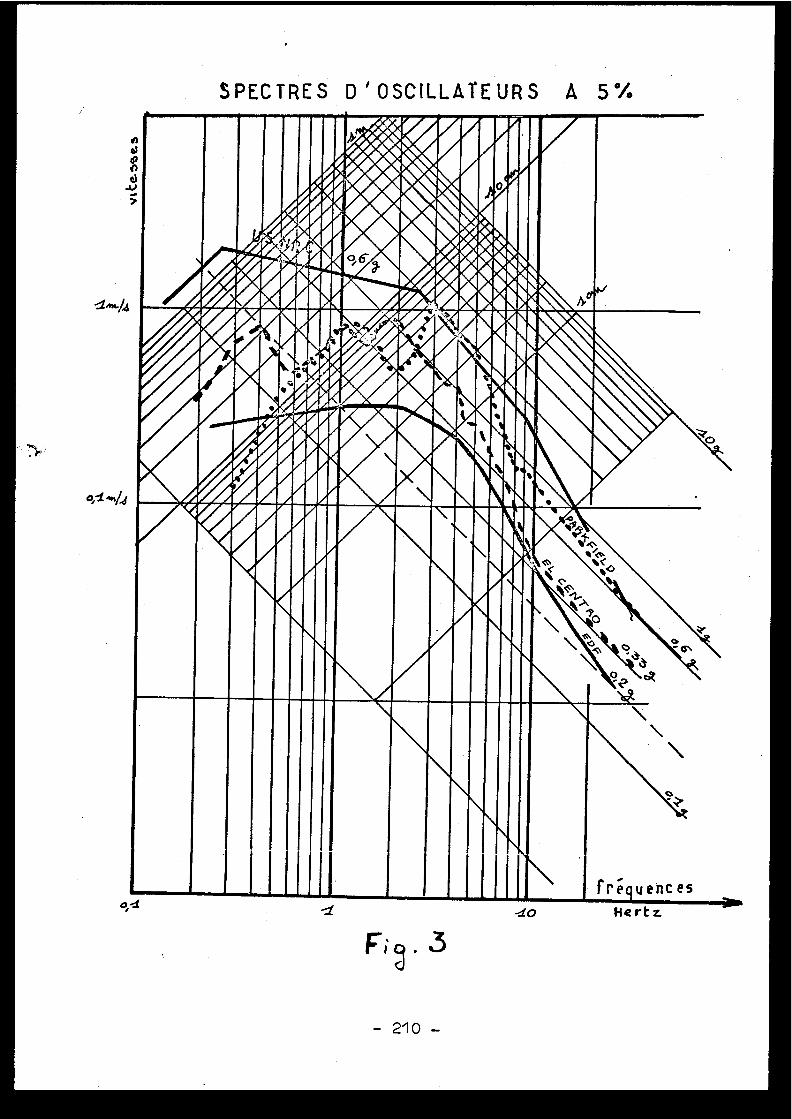
SPECTRES D'OSCILLATEURS A 5 %
40 *'s.9
1
100$0*4n*o
w e b
404WA04pr$ir*~P'l0,4 4**
.eVA
4m~.~
s
gP~.
Ir
' -'rr
0g.Og40AAugill.,LL6.rrqrl%
n \\\\
il ,
"ffI1111111• 11111 I fréqu encea
o, ao Hert z
- 210 -
On voit que le dernier cas est irréalisable pou rdeux raisons :
a) on ne sait pas encore faire des appuis de plus de1,5m de côt é
b) on ne peut pas descendre au dessous du nombre de 3appuis et ici il n'en faudrait qu'un seul .
Disons aussi que le spectre USAEC REG-1-60 es tirréaliste au dessus de 0,3g, particulièrement A ces .bassesfréquences . . Rien en effet n'a jamais été enregistré d'auss ifort dans cette gamme de fréquence .
PROBLEME DES DEPLACEMENT S
Nous avons vu qu'avec le néoprène pourvu que le séismene soit pas trop fort on peut abaisser le niveau de l'accélé -ration d ' un bâtiment à un niveau-très raisonnable . Mais endiminuant les accélérations nous avons augmenté les déplace-ments et ceci va poser des problèmes car un bâtiment nucléair eest toujours relié à des bâtiments voisins par des tuyaux, de scâbles électriques ou des rails d'appareils de manutention . Ce sdéplacements sont si importants que les solutions habituelles -- :d'assouplissement des liaisons deviennent prohibitives .
Il est alors nécessaire de synchroniser les bâtiments ,c'est à dire de leur donner la même fréquence etle même mou-vement . La deuxième condition découle naturellement de la pre-mière . mais si, l'hypothèse d'un mouvement du sol entièrementen phase pour l'ensemble des bâtiments à synchroniser n'estplus tout à fait vraie, il se produit alors des déphasages .
'Il est d'ailleurs assez difficile de réaliser deu xbâtiments ayant la même fréquence, cela suppose que la pressionet la qualité des plots de néoprène sont rigoureusement uni -formes .
Un moyen bien plus simple est d'accrocher les bâtimentsentre eux par un dispositif assurant une solidarité dans unplan horizontal (plancher commun, radier commun, . . . ) . fig 4 et 5 .
Nous avons vérifié que pour deux bâtiments l'un de60 000 t l'autre de 40 000 t ayant une différence de fréquenc ede 10% et soumis au spectre E .D .F . A 0,lg l'effort de synchro-nisation était de 450 t ; cet effort est inférieur d'un facteur10 aux efforts de retrait du béton ou de dilatation thermique . fig 6 .
REFERENCES, D'EMPLOI DU MATERIA U
En EUROPE et surtout en FRANCE la technologie des appui sen néoprène fretté a déjà 30 ans d'âge, elle a été lancée pa rM. FRESSINET parallèlement avec la précontrainte .
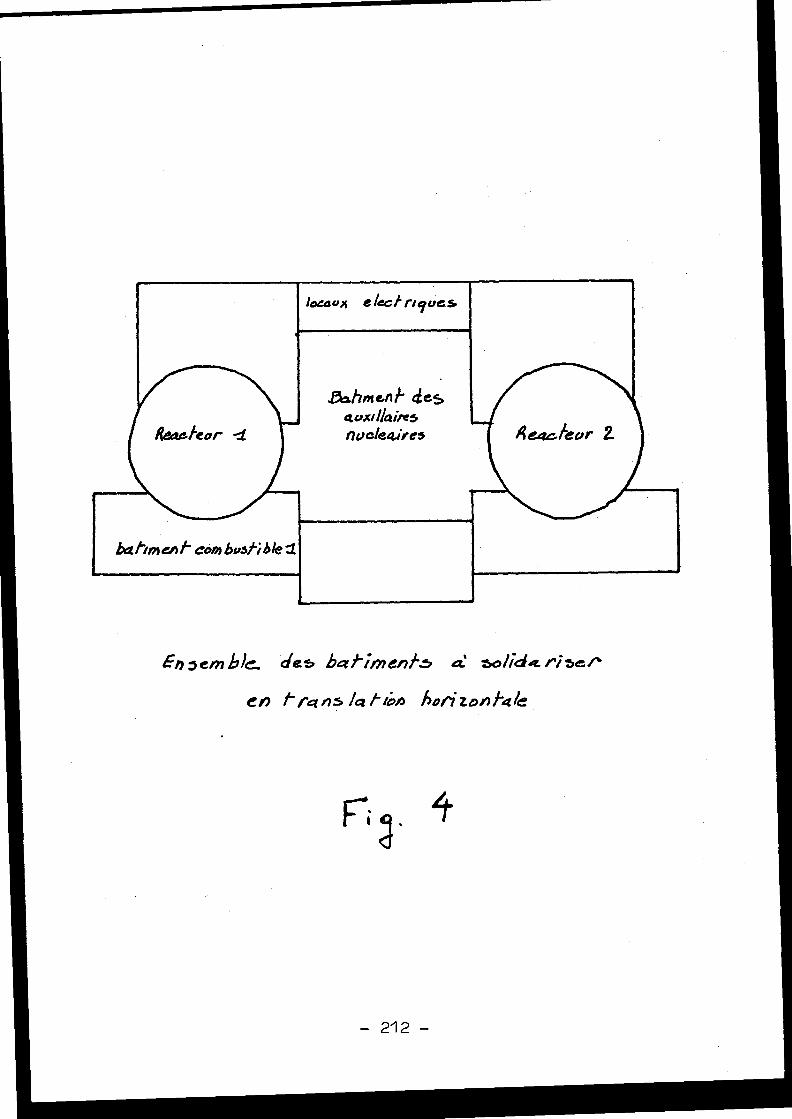
locaux e leaf tique s
.F3,.hnien/- ciesaux' /laites
Rea fear
nuc/eaires
Reacfeor 2
bettin)enf corn bvshble zl
En3ernbid, des bee/IO)CnfS
SoliGi4.risir`
eh /- /'ans /at rron hoyi Zonfafe
If
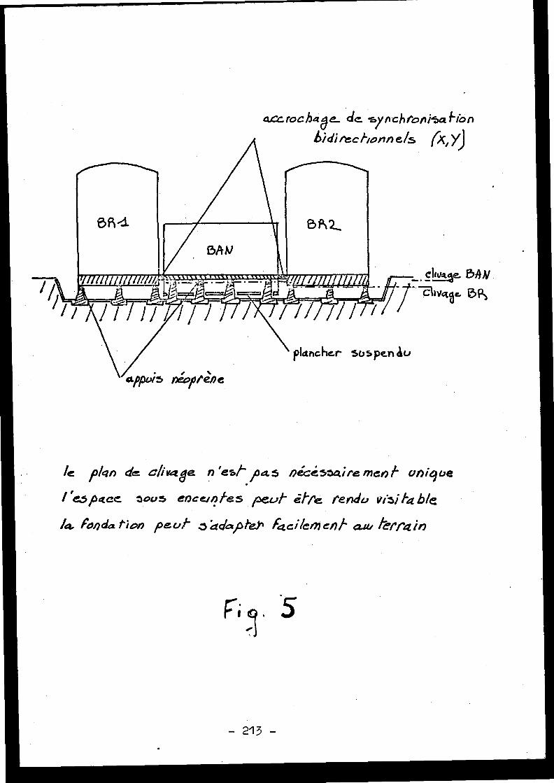
le plgn de c/iverge n 'esr / a. 5 De:c5actiremenf unique
/ é3pace tous ence/nfes peu/ i/r tendu vii fa hie
la Fonda tion peut z ddap1eY, facile/lien/ aw terrain
accrochage_ dam. .sy chtonisa bio nbid) rec. /'conn e /s (X, y)
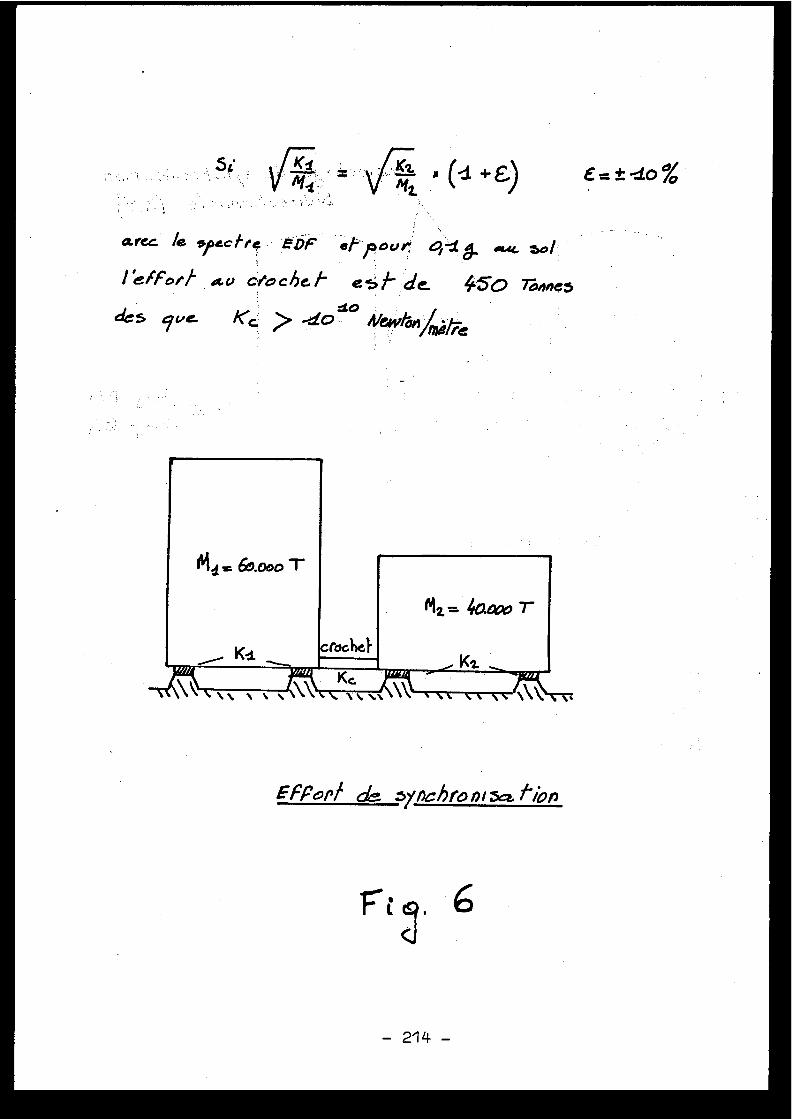
-dO
a.rcc e spectre eDF ot pour
1 /Pori av c/'ochat es/- de. 45o Tones
dcs cwe. Kc > -10 A/ewla,t /tic
EFFonf depynchro n'. tion
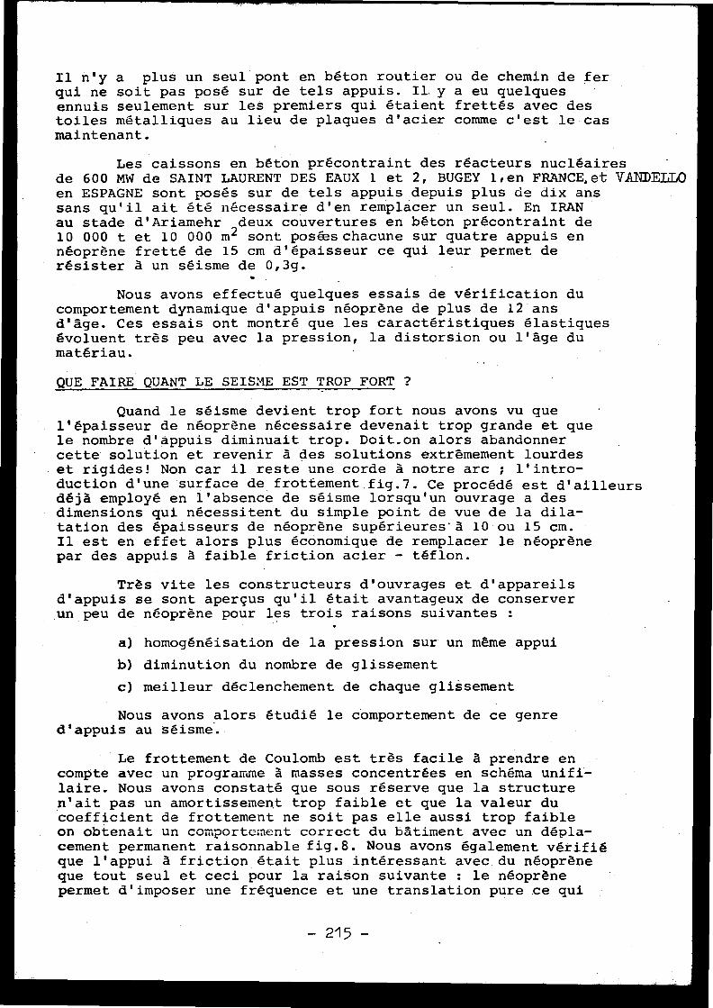
Il n'y a plus un seul pont en béton routier ou de chemin de fe rqui ne soit pas posé sur de tels appuis . Il.y a eu quelquesennuis seulement sur les premiers qui étaient frettés avec de stoiles métalliques au lieu de plaques d'acier comme c'est le ca smaintenant .
Les caissons en béton précontraint des réacteurs nucléaire sde 600 MW de SAINT LAURENT DES EAUX 1 et 2, BUGEY l ' en FRANCE,et VANDELLOen ESPAGNE sont posés sur de tels appuis depuis plus de dix an ssans qu'il ait été nécessaire d'en remplacer un seul . En IRANau stade d'Ariamehr deux couvertures en béton précontraint d e10 000 t et 10 000 m2 sont posées chacune sur quatre appuis e nnéoprène fretté de 15 cm d'épaisseur ce qui leur permet d erésister à un séisme de 0,3g .
Nous avons effectué quelques essais de vérification d ucomportement dynamique d'appuis néoprène de plus de 12 an sd'âge . Ces essais ont montré que les caractéristiques élastique sévoluent très peu avec la pression, la distorsion ou l'âge d umatériau .
QUEFAIREQUANTLE SEISME EST TROP FORT ?
Quand le séisme devient trop fort nous avons vu qu el'épaisseur de néoprène nécessaire devenait trop grande et qu ele nombre d'appuis diminuait trop . Doit_on alors abandonne rcette solution et revenir à des solutions extrêmement lourde set rigides! Non car il reste une corde à notre arc ; l'intro-duction d'une surface de frottement .fig .7 . Ce procédé est d'ailleur sdéjà employé en l'absence de séisme lorsqu'un ouvrage a de sdimensions qui nécessitent du simple point de vue de la dila-tation des épaisseurs de néoprène supérieures'à 10 ou 15 cm .Il est en effet alors plus économique de remplacer le néoprènepar des appuis à faible friction acier - téflon .
Très vite les constructeurs d'ouvrages et d'appareil sd'appuis se sont aperçus qu'il était avantageux de conserve run peu de néoprène pour les trois raisons suivantes :
a) homogénéisation de la pression sur un même appui
b) diminution du nombre de glissemen t
c) meilleur déclenchement de chaque glissemen t
Nous avons alors étudié le comportement de ce genred'appuis au séisme .
Le frottement de Coulomb est très facile à prendre e ncompte avec un programme à masses concentrées en schéma unifi -laire . Nous avons constaté que sous réserve que la structur en'ait pas un amortissement trop faible et que la valeur d ucoefficient de frottement ne soit pas elle aussi trop faibl eon obtenait un comportement correct du bâtiment avec un dépla -cement permanent raisonnable fig .8 . Nous avons également vérifi éque l'appui à friction était plus intéressant avec du néoprèneque tout seul et ceci pour la raison suivante : le néoprènepermet d'imposer une fréquence et une translation pure ce qu i
-215-
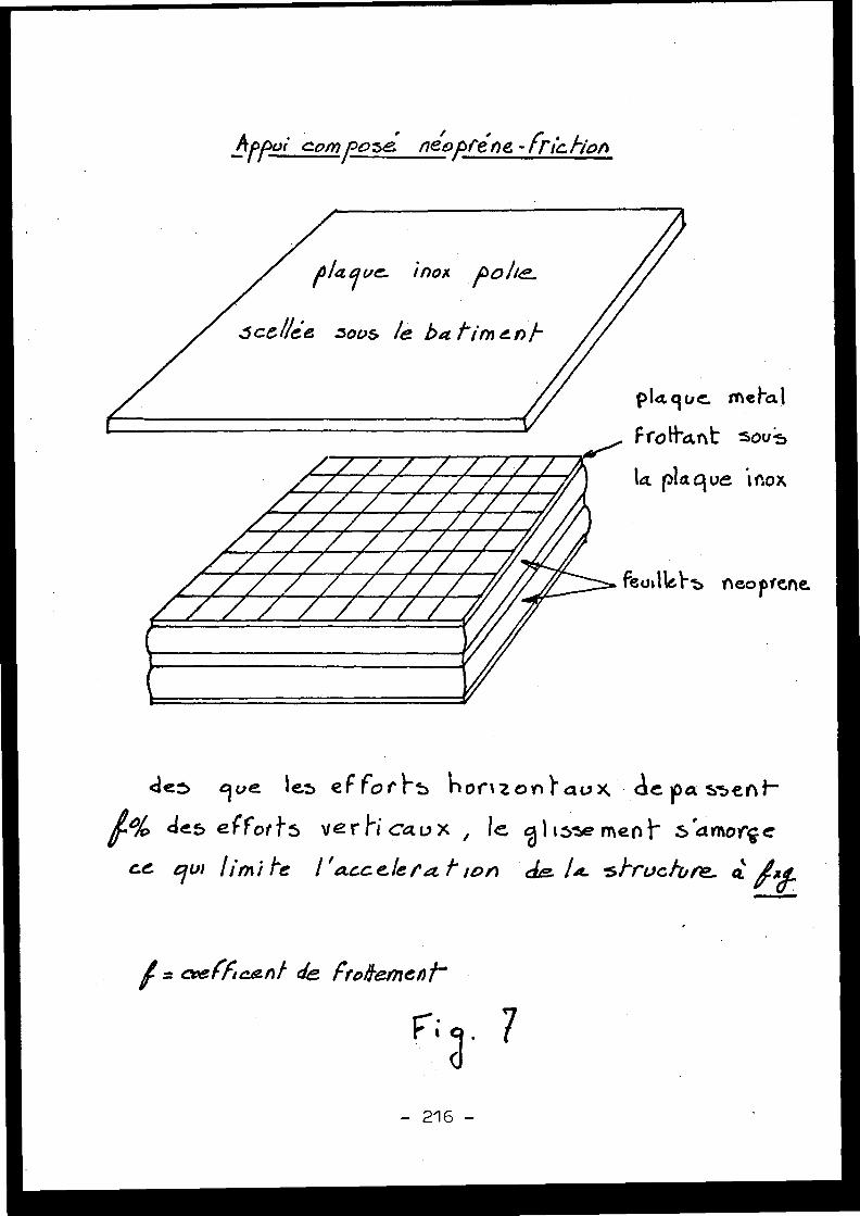
a4pPoi corposé néofvéne -Friction
iiii i~i~ArArAlmrArArArArArd
AIMAllsarAmirArAr
AlrdrWAVAIIIAMIArt.n
dew 9ve fes eF & rl-5 %or'Izon) aux dc pa ssent'
1o/ des eÇforfs vert-i caux , le c01i5se ynerlt" Samorç e
ce eJu! lirnife / 'ace elepQf ion
L . si-rvcl,m eZ /x.
1= c+e(ficenf de Ftoi}emenf-
ptct9vc meta l
Frôtf'a,nt sou p
la plaque ir .ox
feusIlel-s ,neopfene.
- 216 -
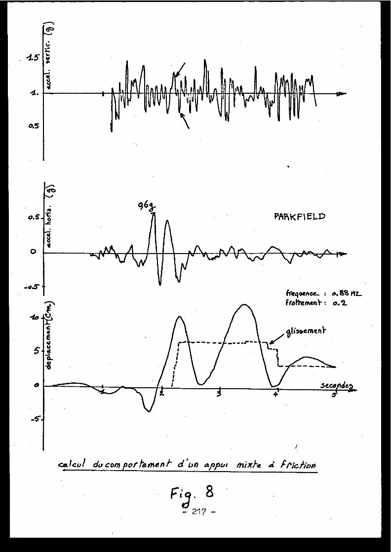
4.
h
-.5
0,5
O .
963.o.S
-0.5'
calcul dvcornpor fev9len 1- d ~W) arpul mixl-e
F/'ic fioo
permet au cours de la partie linéaire du déplacement de donne rune vitesse initiale uniforme au bâtiment qui au delà de l acapacité de rappel de l'appui glissant continue sur sa lancé esans apporter d'amplification par balancement . Sur toute lahauteur l'accélération reste donc égale et écrêtée à la valeu rdu produit de la masse du bâtiment par l'accélération vertical etotale instantanée : (pesanteur + séïsme vertical) et par l ecoefficient de frottement .
La s~ilution appui mixte (frottement + néoprène) présente-- - donc des avantages supérieurs à ceux du néoprène seul par :
1) choix de la fréquence de fonctionnement (par l'épais -seur et la surface )
2) choix de l'accélération maximale (par le coefficien tde frottement )
3) existence d'un seuil en dessous duquel la structur eest élastique
4) absence de limites de l'accélération horizontal ed'excitation .
L'utilisation rationnelle de ces paramètres aboutit àadapter le coefficient de frottement soit à la capacité maxi -male d'une structure standart donnée que l'on veut installe rsur un site exceptionnellement sismique, soit au séisme norma ladmissible,aucun déplacement permanent ne devant alors avoirlieu .
Remarquons au passage que le seul effet d'un séisme qu imobilise les vertus de la friction est de déplacer la structurede quelques 10 à 30 cm sans absolument aucun autre dégât quel'allongement excessif de quelques liaisons sur lesquelle son peut alors concentrer tous ses efforts d'engineering .
REPERCUSSIONSUR LESEQUIPEMENT S
Tous les planchers ayant pratiquement le même mouvement ,il n'est plus pénalisant d'installer un matériel lourd à un ecôte élevée, ce qui règle le problème du choix des emplacements .Le mouvement ayant lieu à basse fréquence, l'amplification dyna-mique se produit en dehors de la bande de fréquence de 3 à'1 0hertz où se trouvent les équipements . Ils ne sont donc soumisqu'à une accelération quasi statique égale au produit de l'acce-lération verticale maximale par le coefficient de frottemen tcomme le montre la figure 9 .
TECHNOLOGI E
La technologie et la mise en oeuvre des appuis purementélastiques sont actuellement très bien connues puisqu'ils sontutilisés par les Ponts et Chaussées et les chemins de fer depui s1945 . Par contre celle des appuis à friction fait l'objet d'étude simportantes de la part d'E .U .E . et de la société SPIE-Batignolles ,études qui seront exposées prochainement dans la presse techniqu espécialisée .
- 218 -
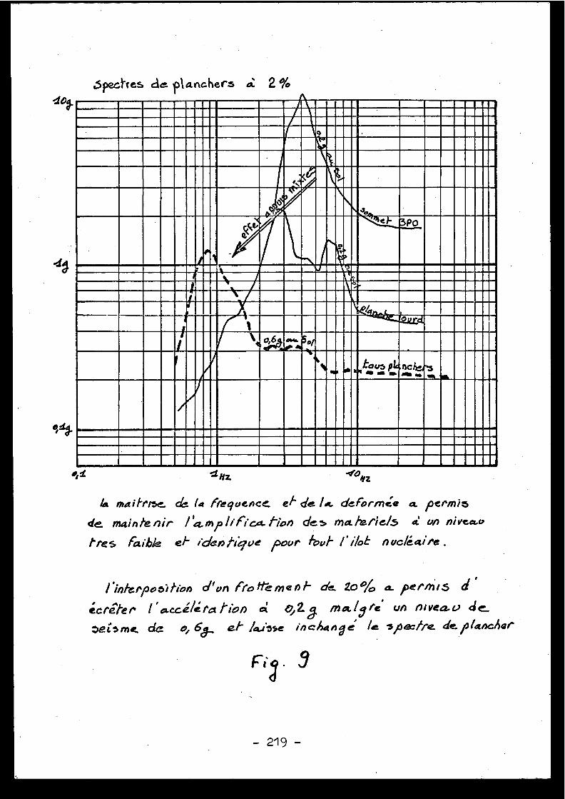
Spectres da. ,Marchers aa 2 %
~ Nz 4o4z
la maifr,se dc !a frequence of de l. . defornnée a, permis
de. maintenir / cpm/ /iPica. /Yon des ma /-i/'ie/5 a an nivea.v
Pres faible el- ic/aAligve pour /buf /' i/ob nuc/Caire .
rinte/`pooitioA d'vn (te !1 meni- de. 20% a. Permis d
écrêfer 1 ' u.ccélcta /io» ai 0, 2j ma.l/ re~ un nlvea, d e
*e me. de o, 6cl,. . oflause incha Age' /e s,oec/re de.,lanclior
Ft . 9
General Discussion
Discussion générale
N.N. AMBRASEYS, United Kingdom
. The problems of soil layering, non-linearity o ffoundation and building materials, soil structure interactionand the foundation-bedrock radiation require solution in thei rsimplest form, perhaps in one dimension before we can use wit hconfidence more complex numerical solutions . Real materialproperties are little known and it is their properties thathave to be studied first before any significant advancementis made .
Any laboratory testing which will help us to under -stand what we mean by liquefaction, or loss of strength, shouldbe designed to represent the real phenomenon . We have to pro -duce more realistic laboratory experiments, to detect th eproperties of the materials . Tests should perhaps be as sophis -ticated as the numerical techniques we're using for the solu -tion of the problems .
J .R . HALL, United State s
Impedance between soil and rock is an important con-sideration in dynamic problems . If the rock is assumed to b einfinitely rigid, radiation damping does not exist until a"critical frequency" is reached because of a surface wave mod ehaving infinite velocity .
Liquefaction testing in the laboratory certainly haslimitations relative to boundary conditions particularly fo rvertical cyclic loading of cylindrical specimens .
Many publications exist of experimental verificationof radiation damping . The results agree very well with theore -tical predictions .
D . HITCHINGS, United Kingdom
The Figures 2 and 5 of Paper 4.1, which I shal lpresent this afternoon, show the soil-structure response fora simple model with non-reflecting boundaries . A horizontalshear pulse is applied at the base of the soil . This causesa travelling shear wave which excites the structure . The res -ponse at the top of the structure shows the characteristi cdamped vibrations although there is no damping in the struc -ture itself, all of the damping comes from radiation into th esoil .
J .V . PARKER, United Kingdom
I would like first to refer to Professor Ambraseys 'remarks in relation to a more realistic treatment of the soil -structure interaction problem with regard to material proper -ties . The real problem at the moment is that in spite of th efact that material properties for the soil are not availabl ewe must still analyse the behaviour of the structure in orde rto design plant to withstand seismic conditions . We can onlyuse existing data and consequently very idealized materia lproperties in the soil-structure interaction model .
For soil-structure models idealized assuming thatthe soil is elastic, the lumped mass foundation model willgive virtually the same answers as a finite element foundatio nmodel provided that only the rigid body modes of the founda-tion raft are of interest eg . horizontal and vertical trans -lation, rocking and twisting modes . If higher modes are ofinterest or if flexing of the foundation raft is important ,then the lumped mass foundation model is inadequate .
J .F . VERNET, France
Les expériences de liquéfaction peuvent se faire a ulaboratoire . Les plateformes de forage pétrolier posées surle fond de la mer sont agitées par le mouvement des vagues e tcela liquéfie le sable du fond, ce qui risque d'entraîner de smouvements allant jus9u'à la rupture des tuyauteries rigides .Ces phénomènes ont éte parfaitement reproduits au laboratoire ,et c'est pour moi une nouvelle occasion de vous inviter àvisiter le nouveau centre de recherches de l'Ecole Polytech-nique à Palaiseau . Pour les effets de la plasticité au voisi-nage de l'épicentre d'un tremblement de terre, je signale le stravaux sur la plasticité de Jean Mandel, Louis Brun (OEA) ,Yannick d'Escatha, Jean Salençon, ou le Laboratoire de Méca-nique des Solides .
J .R.HALL, United States
There are in fact quite a few publications in th eliterature with experimental results illustrating that radia -tion damping does indeed exist and it agrees very well withtheoretical calculations .
D . COSTES, Franc e
Il me semble que peu d'analyses ont été publiée ssur les mouvements réels du sol et des structures, permettantde vérifier les divers calculs .
C .G . DUFF, Canada
In answer to Mr. D . Costes'question on the availabi -lity of actual measured data for determining soil-structureinteraction effects, I wish to indicate that Dr . Hans Rainerof the National Research Council of Canada is relevant .Dr . Rainer's work has been based on actual observed effect son buildings subject to ambient or induced vibration (swaying )on various kinds of foundations and soils (rock, soft soils, 'piled or unpiled) . Soil damping values up to . 40 % have beenobserved (combined material and radiative damping) for sof tsoils .
Dr. Rainer's work has been published in a number o fjournals, the most recent paper being that given at the secondCanadian Earthquake Conference, McMaster University, Hamilton ,Ontario, June 5-6, 1975 .
The soil properties (damping and spring rates )determined by Dr . Rainer's empirical relationships have beenapplied regularly to the soil-structure interaction analysi sof Canadian nuclear plants .
C . PLICHON, Franc e
Je voudrais signaler le cas du séisme récent d eFerndale qui a entraîné pour la centrale de Humboldt Bay un eaccélération "free field" de 0,35 g et pour le caisson duréacteur BWR de 60 MW enterré 0,2 g en surface et 0,15 g à25 m de profondeur . Une étude de l'interaction sol-structur ea été faite par Dames and Moore qui n'explique que partielle -ment ce comportement .
G . KLEIN, F .R. of Germany
After this morning's presentations it seems to m ethat the existing gap between scientists and engineers become swider and wider . As Mr . Ambraseys said yesterday we have t oformulate problems before solving them . I have sometimes theimpression that we are forgetting the main problem which weare faced with in this meeting, namely the protection o fnuclear power stations against earthquakes . We have developedsophisticated methods to investigate soil-structure interac-tion, wave-length influences, etc ., but there are only weakquestions about the accuracy of the material data we put inonr calculations . Let us remember that the results of th emost complicated computer programs are not better than th ematerial data used in these programs . But we all know that thesoil data we obtain from field or laboratory investigation sare very poor . In consequence our studies should be concen-trated on a realistic determination of such data.. It could b ethat such a determination for soil data is not yet available .Well, a scientist in this case makes assumptions, an engineeron the other hand has to solve his task which is - I repeat -
- 222 -
the protection of the nuclear power station . He must look forother ways to solve his task and I am very thankful t oMr. Plichon that he has demonstrated us such a way - th eisolation of the power station or part of it . In Germany ,this isolation of parts of power stations, i .e . turbine-sets ,is highly developed and in recent years turbine-sets wit hweights of about 8,000 t . including the mat were also protec -ted against earthquakes by springs and dampers . I believe thatwe have with the isolation technique a powerful tool agains tearthquakes and I ask for our attention to this technique .
H . SHIBATA, Japan
To eliminate the uncertainties of earthquakes, soil sand others, introducing a certain new engineering device seem sto be useful . However, it has a possibility to introduce ano-ther difficulty for the over-all system again . .So we shouldcarefully examine details on the nature of earthquakes fo rengineering design by the scientist's eye .
P.GIULIANI, Italy
What is the effect of aging on neoprene's mechanica lcharacteristics ?
C . PLICHON, France
Le néoprène est utilisé en France depuis la second eguerre mondiale, c'est-à-dire. que nous avons plus de 30 an sd'expérience .
Les caissons précontraints de centrales graphite -gaz sont tous posés sur néoprène, notamment Saint-Laurent desEaux depuis onze ans . A côté de cette centrale, il y a un emaquette de 70 tonnes posée depuis douze ans sur trois appuisen néoprène de 200 x 200 mm et 2 x 12 mm d'épaisseur de neo-prène . Récemment, nous avons mesuré les caractéristiques élas-tiques de ces appuis par un essai en vibration libre à partird'une distorsion unite . Nous n'avons pas trouvé de difference ssignificatives avec un néoprène neuf ; par contre, et cec iest plutôt dû à la forte distorsion, nous avons observé plu sd'amortissement que nous croyions : 7 % au lieu de 5 %, etceci est une bonne nouvelle .
J .P. WOLF, Switzerland
How do the neoprene pads affect the response due toa vertical earthquake ?

C . PLICHON, Franc e
La raideur verticale du néoprène est très grande ;il n'a donc pas d'effet sur la réponse de la structure auséisme vertical sans néoprène .
J .P . WOLF, Switzerland
Due to variations of the friction coefficients anddue to the even slight effect of rocking, not all frictionplates will lock or start sliding at the same time . Does thisaffect the floor response spectra (high frequency range) fo rpoints in the structure ?
C . PLICHON, Franc e
Les variations du coefficient de frottement ou d ela force verticale dues soit au moment du renversement soitau séisme vertical ont évidemment un effet sur l'instant dedépart ou d'arrêt de la friction mais ceci semble sans effe tsur le spectre de plancher à cause sans doute de l'élasticit édu néoprene . En tout cas, l'essai d'une maquette posée su rquatre appuis ne l'a pas montré .
N .N . AMBRASEYS, United Kingdom
Nature has provided most sedimentary deposits withartificial neoprene layers (e .g . high clay content layers ,lake deposits) . So, you may not be needing neoprene layer sif your foundation really is on anything but solid rock .
C . PLICHON, Franc e
Je voudrais ajouter que je ne pense pas que, parexemple pour des pays moyennement sismiques ou peu sismiques ,il soit nécessaire de mettre toutes les centrales sur desappuis néoprène . La visite récente que nous avons faite à l acentrale de Humboldt Bay le prouve . Ce site est relativemen tsableux . Je pense que sur un terrain normal on ne peut pasobserver de liquéfaction, il y a tout au plus en certain sendroits un tout début de liquéfaction qui permet des com-portements de structure de ce type là . Autrement dit, pou rdes séismes moyens, je pense qu'on pourrait se contenter d ece que fait de bien la nature .
H . SHIBATA, Japan
How do we assume the waves are to come to a parti-cular structure, especially the shear waves ?
- 224-
C . PLICHON, Franc e
Dans le cas où le foyer est sous la structure, lapremière arrivée d'onde est évidemment verticale, mais comm ele séisme dure en général quelques secondes, il y a d'autre sondes qui sont émises ou qui arrivent par suite de réflection sou de réfractions latérales . Je voudrais profiter de cetteoccasion pour préciser que ce qu'on connaît du mécanisme aufoyer provient uniquement du debut de l'enregistrement carla suite en est trop complexe ; on ne connaît donc que ledébut du'mécanisme au foyer .
H. SHIBATA, Japan
At the University of California, Prof . Penzien andhis group made lots of studies on this point . There is aprincipal axis of motion. That axis sometimes fluctuates, bu tduring the main field it almost consists of the absolute coor-dinates of the space . I mean the three principal axes of th eground motion seem to be fixed to the absolute space in sitingdirection of main shock ; the direction between the fault lineand the direction of these three axes seemed to be very clearin the case of the San Fernando earthquake . I think some ade-quate assumptions can be found in this regard . Any comments ?
C. PLICHON, Franc e
Sans répondre vraiment à la question, je pourrai sreparler du séisme de Ferndale où ce que l'on peut remarque rsur les trois enregistrements c'est que seulement l'accéléra-tion est-ouest était beaucoup plus forte que les autres, l eséisme étant à 25 km au sud . Il y a donc sur ces trois enre -gistrements un effet de polarisation horizontale ; on pourraitdonc attribuer la propagation à une onde de Love . Si on s ereporte aux courbes de déplacement, on retrouve sur les troisenregistrements une sorte d'impulsion de déplacement qui pour -rait faire penser à quelque chose comme une onde de choc . Maiscela n'explique pas la totalité de l'enregistrement .
D. COSTES, Franc e
Dans toutes les études sur les mouvements sismiques ,il nous est déclaré qu'il y a très peu de corrélation entr eles mouvements verticaux et les mouvements horizontaux. Dansces conditions, je comprend mal à quel type d'ondes nous avon sréellement affaire . Si nous avions des ondes de Rayleigh, nou saurions une corrélation complète entre les mouvements verti -caux et horizontaux . Est-ce que les autres types d'ondes sontsusceptibles de donner des mouvements verticaux importants età quoi est dû fondamentalement le manque de corrélation entr eles deux mouvements ? Qu'est-ce que le mouvement sismique ?Quelles sont les ondes impliquées, en général, dans un mouve -ment sismique ? Les études d'interaction doivent être orientées
-225-
par une connaissance que l'on a des mouvements sismiques réels .,Quels sont-ils, par nature ?
J .F . VERNET, Franc e
Je n'y connais pas grand-chose, mais il me sembl eque si les ondes importantes sont celles qui montent de l'hy -pocentre vers l'épicentre, cela pourrait être des ondes lon -gitudinales et des ondes transversales qui viennent se réflé -chir sur la surface et qui par conséquent changent de natureen se réfléchissant sur la surface, et que le rapport entrelongitudinal et transversal peut être a priori absolumentquelconque .
H . SHIBATA, Japan
I think it depends on the complexity of the soi llayers around the site . But 1 think it is possible to find adirection of the main field of earthquakes . For engineerin gpurposes, I think we shall use that sort of concept for th edesign. I should now like to ask the following : if there i ssome evidence of uplift during the earthquake by the analysis ,how shall we put criteria for the design ?
J .P . WOLF, Switzerland
In the actual design of the nuclear power plantLeibstadt, for small acceleration values (-'- 0 .2 g) the dynamicresponse including lifting-off and slipping is surprisingl ysimilar to that of a linear analysis . As the foundation matacts as a cantilever, the moments in the plate are, however ,substantially increased (maximum value - 2700 mt/m, se eref . [6] at the end of Paper 3 .2) .
E . ROBERT, Franc e
La question que je voudrais poser n'est pas enrapport direct avec les points particuliers qui viennentd'être discutés ; mais elle s'inscrit dans le thème de cett eSession 3 .
Il s'agit de la vérification de la portance du solde fondation en cours de séisme, en tant qu'elle est sollicité edu fait de l'action sur la structure des composantes horizon -tales dérivant des forces d'inertie engendrées par les séis-mes .
La mécanique des sols fait apparaître que de tellescomposantes horizontales sont susceptibles de réduire de ma-nière importante la capacité de résistance du sol de fondationet donc de s'ajouter encore à l'effet particulier des onde ssismiques sur les caractères mécaniques dudit sol .
-226-

A-t-il été tenu compte de ce fait dans les étude srelatives à la stabilité des fondations des centrales cons -truites ou en cours de construction dans les pays représenté sà notre colloque ?
(No answer - pas de réponse) .


Session 4 - Structures and Equipments
Séance 4 - Structures et Équipements
Chairman - Président
J .V . PARKER
Summary of Session 4
The first four papers dealt with the evaluation ofthe motion induced by a given earthquake .
D . Hitchings (Paper 4 .1) noted that the result sobtained using the method of response spectra were generallypessimistic when the smooth spectrum was worked out from res -ponse peaks, and that the time-history method required nume -rous signals which was an expensive business . He was concernedwith developing a method which directly tackled the random andnon-stationary nature of the signals, by studying the randomresponse of structures and of the ground when excited by ran-dom noise modulated in time (Markov process) . The introductionof probability density functions made it possible to adapt thesignal to a given spectral content . The results of the rando mcalculation would be verified by direct time-history calcula-tions .
C .G . Duff (Paper 4 .2) proposed a graphical methodfor determining the responses of structure and equipment, onthe basis of a given response spectrum for ground movements .For a number of diffèrent frequencies, incident movements wer eapplied in the form of a decremental sinusoidal waveform, thedecrement Bg being adapted to satisfy the spectrum data forthe various damping rates .
M . Livolant (Paper 4 .3) compared the conventionalmethods of structural calculations with respect to an excitin g
. force defined by a spectrum :
- the quasi-static method which was suitable only fo rsimple structures in which a single mode predomina-ted ,
- the modal method in which the structural modeswere assumed to be decoupled and where the intro-duction of modes and their combination require dcertain empirical rules to be applied ,
- the direct or time-history dynamic method, applie dto the principal modes or to all degrees of freedom ,whereby non-linearities could be taken into consi -deration .
In the modal method, the quadratic combination o fmodes generally gave responses lower than those produced bythe direct method .
The author also described a method for constructingfloor spectra directly, based upon Fourier approximations inthe convolution calculations .
- 230 -
H. Shibata introduced the study by Y. Sasaki(Paper 4 .4) on the earthquake behaviour of BWR (Boiling Wate rReactor) fuel assemblies, from the standpoint of water circu-lation. Quarter-scale tests were carried out on a model com-prising twenty-one assemblies under horizontal excitation whichprovided excellent confirmation of a calculational model cover -ing the oblique movements of the fluid . The predominant mod ewas that in which, all assemblies were in phase, a conditio nwhich could be extended to reactor cores .
The verification of structures and equipment involve dnot only evaluating movements and deformations but also analys -ing the performance of materials .
J . Despeyroux, in a statement, made some remark sabout the "levels'" of structure verification used by th einternational commissions : level I involving the adoption o fpoint values representing forces and resistances, invokingthe idea of safety coefficients, and level II where distribu-tion laws for forces and resistances were introduced .(Levels III and IV would concern optimisation on the projec tor national scale) . Certain types of force with non-lineareffects were excluded de facto from being dealt with at level I .Particular attention should be given to the tolerated limitingstates under seismic excitation at the SSE level, having reardto the degree of disaggregation compatible with maintaining 'essential functions .
The question of permissible stress levels in mate -rials, relative to the incident attack level, was then discus -sed with reference to the principles of nuclear safety ; itwas acknowledged to be difficult to cover all possible situa -tions in a probabilistic study .
There was then a general discussion about the variou sanalytical methods and the suitability of making direct timehistory calculations . J . Parker argued in favour of this me -thod, using a number of representative accelerograms, at leas tat the final stage of verifying detailed designs and in th epresent state of technology . This method would enable non-linearities and inter-mode couplings to be taken into conside -ration . However other participants placed more reliance onquicker methods which embodied the random aspect of earthquak eforces .
Then again, probabilistic elements were implicit i nall the methods, notably in defining the response spectrum .It was therefore generally very difficult to assess the safet ymargins actually employed with regard to this or that hypothe -sis . Similarly it was obligatory to retain margins in assessin gdamage since behaviour beyond the elastic limit was very diff i -cult to evaluate .

Résumé de la Séance 4
Les quatre premières communications traitent del'évaluation des mouvements induits par un séisme donné .
D . Hitchings (Communication 4 .1) constate que laméthode des spectres de réponse donne des résultats générale -ment trop pessimistes lorsque le spectre lissé est developp éà partir des pics de réponse, et que la méthode des descrip-tions temporelles (time history) nécessite le p assav de nom -breux signaux, ce qui est onéreux . Il s'attache à developerune méthode prenant directement en compte le caractère alea-toire et non stationnaire des signaux, en étudiant la répons ealéatoire de la structure et du sol, excités en bruit aléatoir emodulé temporellement (processus de Markov) . La prise en compt edes fonctions de densite de probabilité permet l'adaptationdu signal à un contenu spectral détermine . Les résultats ducalcul aléatoire seront vérifiés par des calculs temporel sdirects .
C .G. Duff (Communication 4 .2) propose une méthodegraphique de détermination des réponses de la structure e tdes équipements, en partant d'un spectre de réponse donné pour-le mouvement au sol . Pour une collection de frequences, o napplique des mouvements incidents en sinusoïde décroissante ,le décrément Bg étant adapté pour satisfaire aux données duspectre pour les divers amortissements .
M. Livolant (Communication 4 .3) compare les méthode sclassiques de calculs de structures vis-à-vis d'une excitationdéfinie par un spectre :
- la méthode quasistatique qui ne convient que pourles structures simples où un mode prédomine ,
- la méthode modale où l'on suppose les modes destructure découplés et où la prise en compte et l acombinaison des modes nécessite certaines règle sempiriques ,
- la méthode dynamique directe ou temporelle, appli-quée aux modes principaux ou à l'ensemble des degré sde liberté, ce qui permet de prendre en compte le snon-linéarités .
Dans la méthode modale, la combinaison quadratiqu edes modes fournit en général des réponses inférieures à celle sde la méthode directe .
L'auteur décrit également une méthode de construc-tion directe des spectres de plancher, fondée sur des approxi-mations dans les calculs de convolutions en spectres de Fourier .
- 232 -
H. Shibata présente l'étude de Y.Sasaki (Communi -cation 4 .4) sur le comportement au séisme des assemblages d ecombustible d'un réacteur à eau bouillant e ; comte tenu dela circulation d'eau . Des essais ont été realises à l'échell e1/4 sur un modèle à vingt et un assemblages en excitatio nhorizontale, et ont permis une excellente validation d'unmodèle de calcul prenant en compte les mouvements obliquesdu fluide . Le mode prédominant est celui où tous les assem-blages sont en phase, ce qui peut être étendu aux coeurs de sréacteurs .
La vérification des structures et équipements com-porte non seulement l'évaluation des mouvements et déformations ,mais l'analyse du comportement des matériaux .
J . Despeyroux présente, en communication non écrite ,des remarques sur les "niveaux" de vérification de structureadoptés dans les commissions internationales : le niveau Icaractérisé par l'adoption de valeurs ponctuelles représenta -tives des actions et des résistances, ce qui implique la notio nde coefficients de sécurité, et le niveau II où l'on introdui tles lois de distribution des actions et résistance . (Les ni-veaux III et IV concerneraient des optimisations à l'échell ede la construction ou à l'échelle nationale) . Certains type sd'action à effets non linéaires ne peuvent être, par principe ,faites au niveau I . Une attention particulière doit être appor -tée aux états-limites tolérés pour une excitation sismique auniveau SSE, compte tenu du degré de désorganisation compatibleavec le maintien des fonctions essentielles .
La question des niveaux admissibles de sollicitatio ndans les matériaux, en liaison avec le niveau d'agression, es talors discutée en se référant aux principes de la sûreté nu -cléaire ; il est reconnu difficile de couvrir l'ensemble de ssituations possibles, dans une étude probabiliste .
La discussion générale se consacre ensuite aux di -verses méthodes d'analyse et à l'opportunité de pratiquer de scalculs temporels directs (time-history) . J . Parker argument epour l'utilisation de cette méthode, avec de nombreux accélé-rogrammes représentatifs, au moins au stade final de la véri-fication des dimensionnements détaillés et dans l'état actue ldes techniques . Cette méthode permet la prise en compte desnon-linéarités et des couplages entre. modes . Cependant, d'autre sparticipants font davantage confiance dans les méthodes plusrapides qui intègrent l'aspect aléatoire des actions sismiques .
D'ailleurs, toutes les méthodes intègrent implicite -ment des éléments probabilistes, notamment dans la définitio ndu spectre de réponse . Il est donc en général très difficil ed'apprécier les marges de sûreté réellement utilisées corre s -pondant à telle ou telle hypothèse . De même, dans l'apprécia -tion des détériorations, on est obligé de garder des marges ,le comportement au delà de la limite élastique étant très dif -ficile à évaluer .
-233-
[4 .1 ]
THi NON-STATIONARY RANDOM SEISMIC RESPONSE OF STRUCTURE S
D . HitchingsImperial College, London SW7, England .
Abstract
A solution for the seismic excitation of . structures is developed in term sof a non-stationary random response to a non-stationary input . Theearthquake and the response are both described in terms of time varyin gprobability density functions . The analysis is developed in detail fo rGaussian PDF's, which are described solely by mean square values at an ytime . The theory is applied to a simple oscillator . The finite elementrepresentation of a structure resting on an infinite soil half spac emodelled by non-reflecting boundaries is also described and result svalidating the model to pulse time history inputs presented .
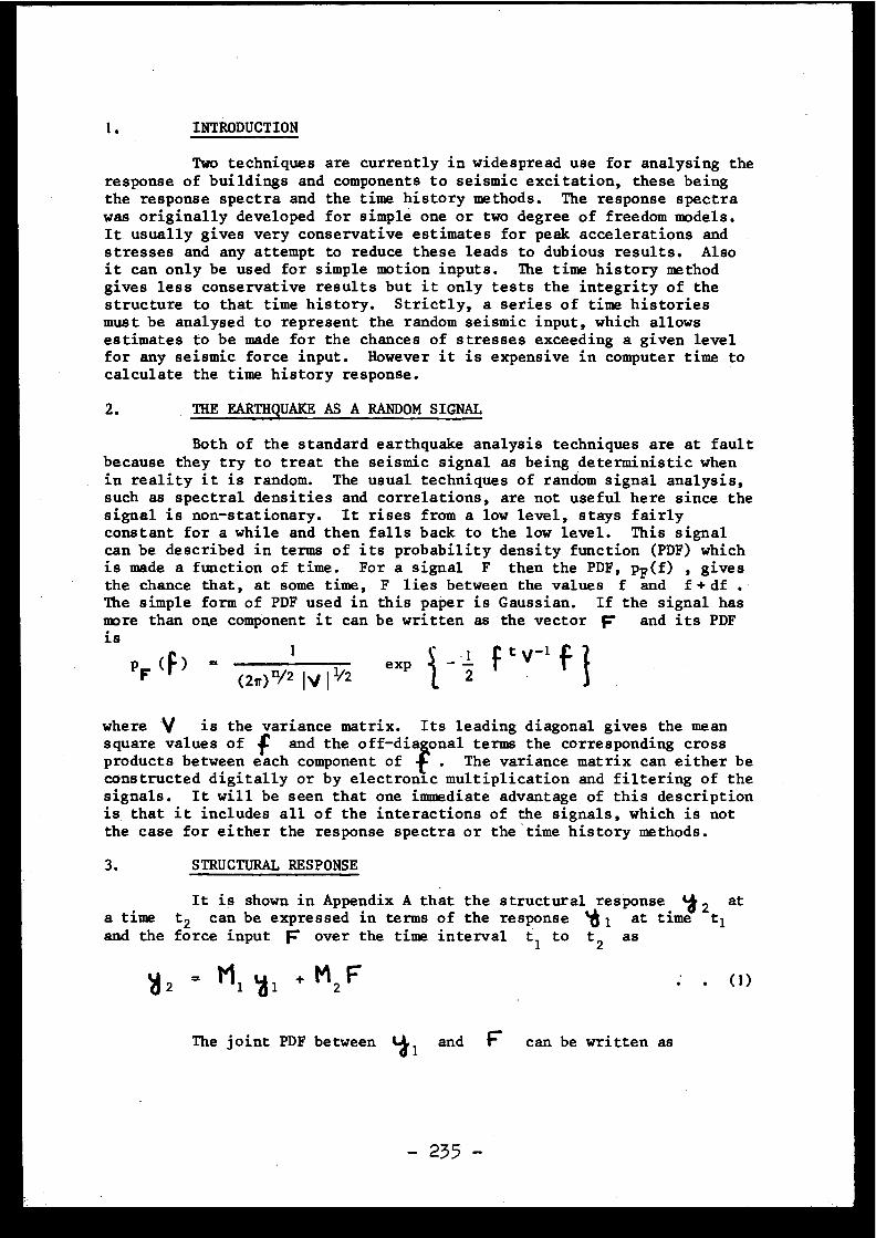
1.
INTRODUCTION
Two techniques are currently in widespread use for analysing th eresponse of buildings and components to seismic excitation, these bein gthe response spectra and the time history methods . The response spectrawas originally developed for simple one or two degree of freedom models .It usually gives very conservative estimates for peak accelerations an dstresses and any attempt to reduce these leads to dubious results . Alsoit can only be used for simple motion inputs . The time history methodgives less conservative results but it only tests the integrity of th estructure to that time history. Strictly, a series of time historie smust be analysed to represent the random seismic input, which allow sestimates to be made for the chances of stresses exceeding a given leve lfor any seismic force input . However it is expensive in computer time tocalculate the time history response .
2.
THEEARTHQUAKE AS ARANDOM SIGNAL
Both of the standard earthquake analysis techniques are at faul tbecause they try to treat the seismic signal as being deterministic whe nin reality it is random . The usual techniques of random signal analysis ,such as spectral densities and correlations, are not useful here since thesignal is non-stationary . It rises from a low level, stays fairl yconstant for a while and then falls back to the low level . This signalcan be described in terms of its probability density function (PDF) whichis made a function of time . For a signal F then the PDF, pF (f) , give sthe chance that, at some time, F lies between the values f and f+ d fThe simple form of PDF used in this paper is Gaussian . If the signal hasmore than one component it can be written as the vector F and its PDFis
PF(F) =(2,r)
n/21IV
1112
exp
12
f t p-1 f
where V is the variance matrix . Its leading diagonal gives the meansquare values of f and the off-dis oval terms the corresponding cros sproducts between each component of f . The variance matrix can either b econstructed digitally or by electronic multiplication and filtering of thesignals . It will be seen that one immediate advantage of this descriptio nis that it includes all of the interactions of the signals, which is notthe case for either the response spectra or the ' time history methods .
3.
STRUCTURAL RESPONSE
It is shown in Appendix A that the structural response 12 ata time t2 can be expressed in terms of the response
at time t1and the force input F over the time interval t 1 to t 2 as
= M 1 y 1 + M2 F
The joint PDF between 41 and F can be written as
- 235 -
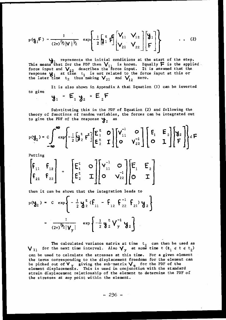
P (I 1F) = 1 1
exp
i
v11 V1 2
(27r)~2 V /2
2
V21 V22
La i represents the initial conditions at the start of the step .This means that for the PDF then \/ 1 is known . Equally F is the appliedforce input and \1Z2 describes the force input . It is assumed that theresponse VI at time t 1 is not related to the force input at this o rthe later time t2 thus making V21 and V12 zero .
It is also shown in Appendix A that Equation (1) can be invertedto give
Substituting this in the PDF of Equation (2) and following th etheory of functions of random variables, the forces can be integrated ou tto give the PDF of the response
12as
:xp
-- 1
t e][E t1 01 Y 11 °
E12 `P 2
E2 I O v 2_2
0E
IZJlF2]
a F
Putting
0 V--11[Et
1
11
.0
E 1 E 2E 2 I o v22
1-
o Ithen it can be shown that the integration leads t o
P(12 ) = C exp - y t (f - ç
-1 F ) y2
2
11
12
22
21
2
1
1
t
- 1
1exp - ÿ
2 Y y(27r) '1'2 1 Vy I p
2
The calculated variance matrix at time t2 can then be used as
V 11 for the next time interval . Also Vy at some time t (t 1 . t t 2 )can be used to calculate the stresses at this time . For a given elementthe terms corresponding to the displacement freedoms for the element ca nbe picked out of V y giving the sub-matrix Ve for the PDF of theelement displacements . This is used in conjunction with the standardstrain displacement relationship of the element to determine the PDF o fthe stresses at any point within the element .
- 236 -
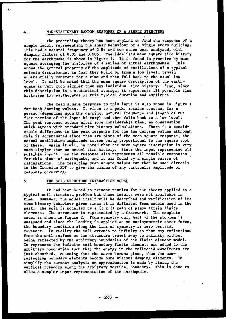
4.
NON-STATIONARY RANDOM RESPONSEOFASIMPLE STRUCTURE
The preceeding theory has been applied to find the response of asimple model, representing the shear behaviour of a single story building .This had a natural freqeuncy of 2 Hz and two cases were analysed, withdamping factors of 0 .05 and 0 .005 . The idealised mean square time histor yfor the earthquake is shown in Figure 1 . It is found in practice by meansquare averaging the histories of a series of actual earthquakes . Thisshows the general property of the amplitude of oscillations of a typica lseismic disturbance, in that they build up from a low level, remai nsubstantially constant for a time and then fall back to the usual lowlevel . It will be noted that the mean square description of the earth -quake is very much simpler than any individual time history . Also, sincethis description is a statistical average, it represents all possible tim ehistories for earthquakes of this typical duration and amplitude .
The mean square response to this input is also shown in Figure 1for both damping values . It rises to a peak, remains constant for aperiod (depending upon the damping, natural frequency and length of theflat portion of the input history) and then falls back to a low level .The peak response occurs after some considerable time, an observationwhich agrees with standard time history calculations . There is a consid-erable difference in the peak response for the two damping values althoug hthis is accentuated since they are plots of the mean square response, theactual oscillation amplitude ratios being proportional to the square rootof these . Again it will be noted that the mean square description is ver ymuch simpler than an actual time history . Since the input represented al lpossible inputs then the response also represents all possible response sfor this class of earthquake, and it was found by a single series o fcalculations . The resulting mean square values can then be used directl yin the Gaussian PDF to give the chance of any particular amplitude o fresponse occurring .
5.
THE SOIL-STRUCTURE INTERACTION MODEL
It had been hoped to present results for the theory applied to a/typical soil structure problem but these results were not available intime. However, the model itself will be described and verification of it stime history behaviour given since it is different from models used in thepast . The soil is modelled by a (3 x 3) mesh of glane strain finiteelements . The structure is represented by a framework . The completemodel is shown in Figure 2 . From symmetry only half of the problem isanalysed and since the loading is applied as an antisymmetric shear force ,the boundary condition along the line of symmetry is zero vertica lmovement . In reality the soil extends to infinity so that any reflection sfrom the soil surface or the structure travel away to infinity withou tbeing reflected by the arbitrary boundaries of the finite element model .To represent the infinite soil boundary finite elements are added to .thearbitrary boundaries such that the energy in the reflected wavefronts arejust absorbed . Assuming that the waves become plane, then the non -reflecting boundary elements become pure viscous damping elements . Tosimplify the current analysis an approximation is made by fixing thevertical freedoms along the arbitrary vertical boundary . This is done toallow a simpler input representation of the earthquake .
- 23? -
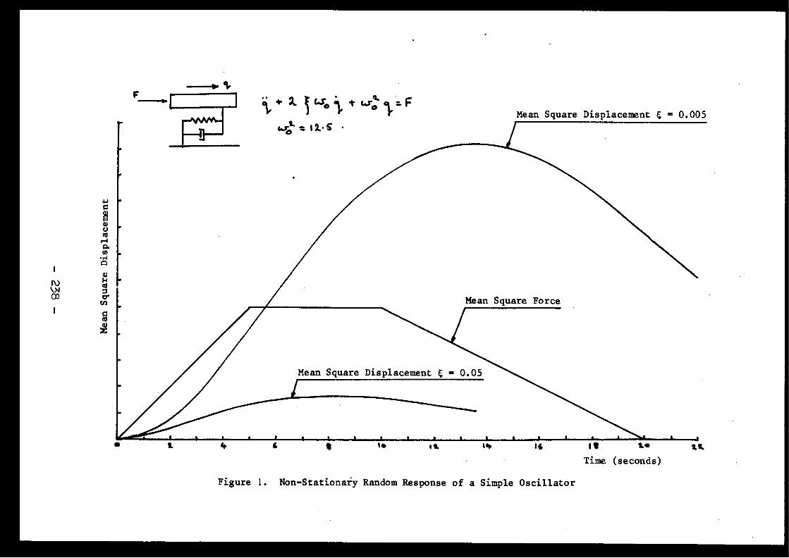
Mean Square Displacement E = 0 .005
Figure 1 . Non-Stationary Random Response of a Simple Oscillator
The loading considered corresponds to a shear wave travellingvertically from the base of the model, and this is applied as shear force salong the bottom edge . In practice the ground motion at the soil surfacein the absence of the building is known. The input forces for the finit eelement model are found by applying these motions to a one-dimensiona lwave equation model and calculating the stress arising from the inciden twave at the depth corresponding to the finite element model boundary . I tis•then assumed that the presence of the building does not affect theincident wave, hence the stress from the one-dimensional model can be use dto calculate the force input for the two-dimensional model . A force o ftwice this magnitude is applied since half is immediately absorbed by th enon-reflecting boundary .
In order to verify the model the soil only was first tested t oshow that it could correctly transmit the shear wave and absorb th ereflected wave . All of these calculations were carried out using th efinite element language FINEL developed at Imperial College . The soil hasa shear wave velocity of 845 ft/sec . With three linear displacemen telements through the thickness the shortest wave that can be represente dhas 1i wavelengths through the depth . This corresponds to a frequency of13 Hz . A shear force with .a time history corresponding to a single perio dsine pulse was applied at the base, representing the incident seismic wave .Figure 3 gives the resulting time history for a 2 Hz pulse where the forc eis applied and at the soil boundary . Considering the velocity response itwill be seen that the base velocity rises to a maximum and falls to zero .This wave travels up to the surface so that the velocity here peaks at atime exactly corresponding to the theoretical time from the peak of bas evelocity . Also the surface wave is of twice the magnitude of the bas ewave, as it should be for the free surface . This surface wave is thenreflected so that it travels back to the base causing a negative peak her eagain at a time exactly as predicted by the wave velocity . This reflecte dwave is then absorbed by the non-reflecting boundary so that the motio nceases . The same observations apply equally to the displacement an dacceleration responses .
Figure 4 gives the same set of response curves for a 10 Hz pulse .Again the relative times between the peaks in the base and surfac eresponse agree with the shear wave velocity . However there is now someunder and overshooting in the response and some ringing when the wav eshould have been absorbed . Even so the response is quite a good approxima-tion considering that the input pulse is 10 Hz and the theoretical maximu mfrequency the model can transmit correctly is 13 Hz . Previous model swithout the non-reflecting boundaries do not transmit high frequencies a swell as this, hence the extra computing complexity involved in finding th edamped eigenvectors is offset by the fact that a coarser mesh can be use dfor the same frequency response .
Figure 5 gives some response time histories for the 2 Hz puls eapplied to the soil structure model of Figure 2 . A full set of analyse sfor more realistic soil-structure interaction problems have been performe din conjunction with Dames and Moore, Consulting Engineers . Actual earth-quake histories were used on parametric studies for nuclear reactor sstanding on a variety of hard, soft and layered soils . The results o fthese analyses will be published in the near future .
- 239 -
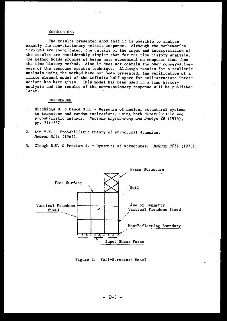
CONCLUSIONS
The results presented show that it is possible to analys eexactly the non-stationary seismic response . Although the mathematic sinvolved are complicated, the details of the input and interpretation o fthe results are considerably simpler than for the time history analysis .The method holds promise of being more economical on computer time thanthe time history method . Also it does not contain the over conservative -ness of the response spectra technique . Although results for a realisti canalysis using the method have not been presented, the verification of afinite element model of the infinite half space for soil-structure inter -actions has been given. This model has been used in a time histor yanalysis and the results of the non-stationary response will be publishe dlater.
REFERENCES
1. Hitchings D. & Dance S .H . - Response of nuclear structural systemsto transient and random excitations, using both deterministic an dprobabilistic methods . Nuclear Engineering and Design 29 (1974) ,pp . 311-337 .
2. Lin Y .K. - Probabilistic theory of structural dynamics .McGraw Hill (1967) .
3 . Clough R.W . & Penzian J . - Dynamics of structures . McGraw HiZZ (1975) .
Frame Structur e
Free Surface
Vertical Freedoms =~- Line of Symmetryfixed
Vertical Freedoms fixed_.
Figure 2 . Soil-Structure Model
- 240 -
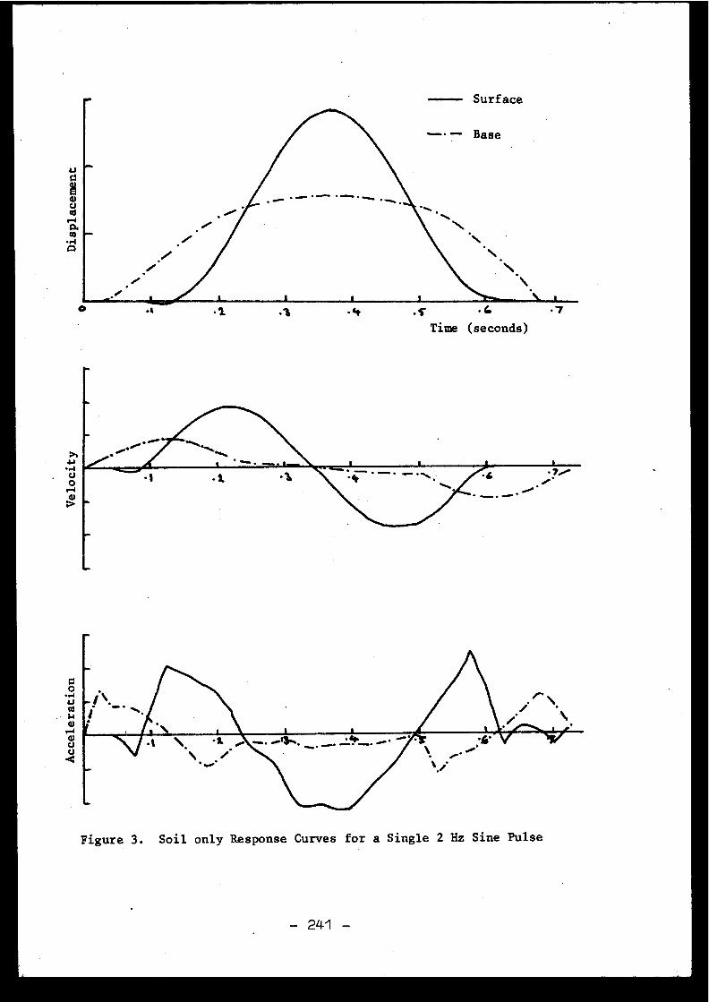
.~
.~
•4~ .
s
Figure 3 . Soil only Response Curves for a Single 2 Hz Sine Puls e
- 241 -
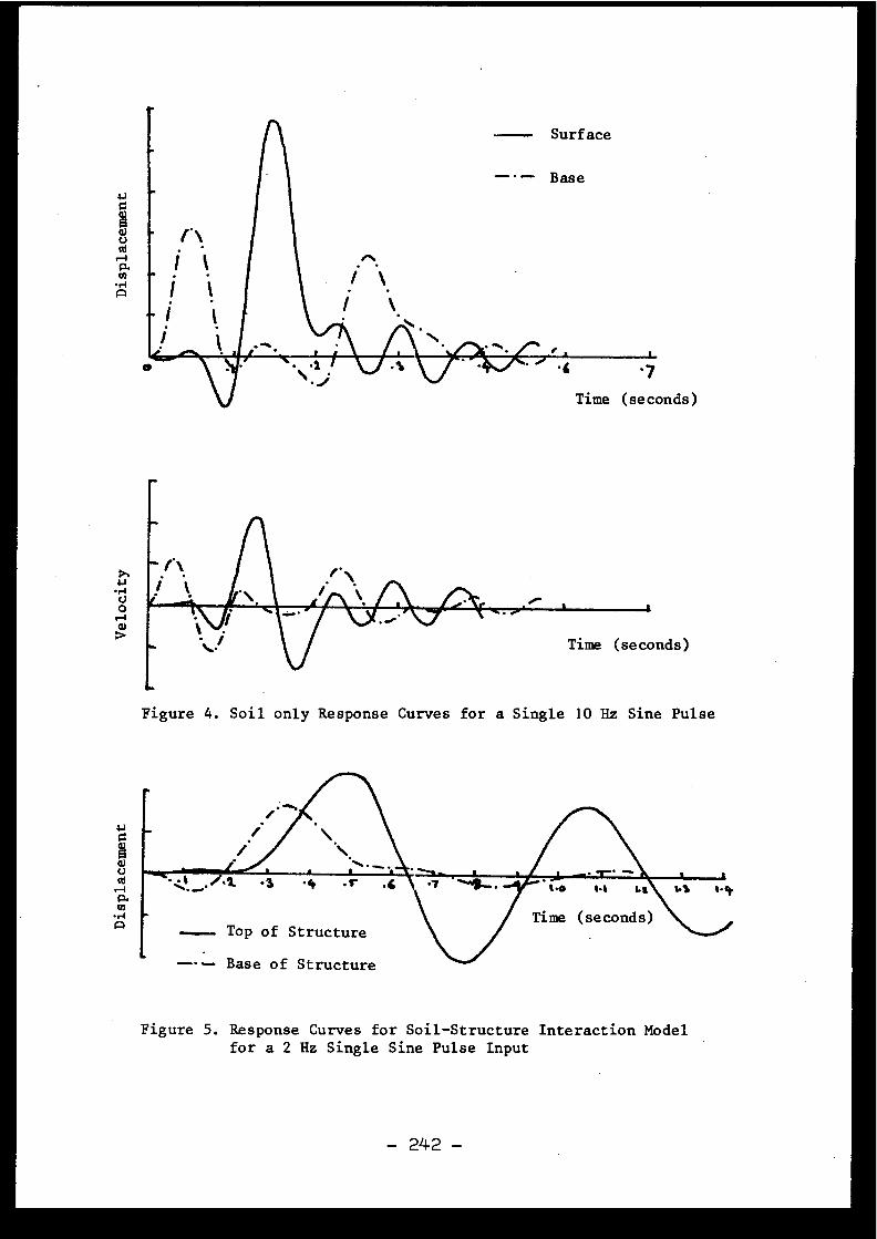
Figure 4 . Soil only Response Curves for a Single 10 Hz Sine Puls e
Figure 5 . Response Curves for Soil-Structure Interaction Mode lfor a 2 Hz Single Sine Pulse Inpu t
- 242 -
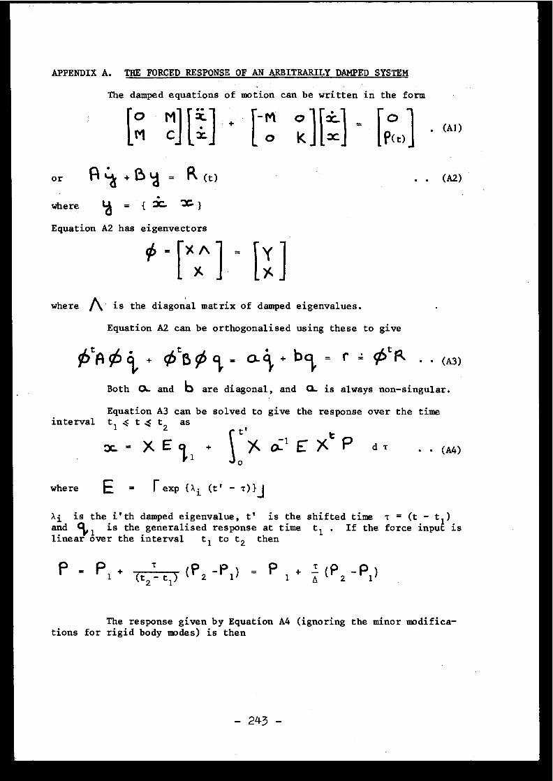
APPENDIX A . THE FORCED RESPONSE OF AN ARBITRARILY DAMPED SYSTEM
The damped equations of motion can be written in the for m
to M . + M o X
o
M c z
O k x
p(t)
. (A' )
where
7C. = 1
Equation A2 has eigenvector s
_ )( A
where n is the diagonal matrix of damped eigenvalues .
Equation A2 can be orthogonalised using these to give
OtAO t + 0t501, = a c', + b c~ = r = 0tR . . (A3)
Both 0. and b are diagonal, and CL is always non-singular .
Equation A3 can be solved to give the response over the tim einterval t
1
t
t2 ast
XE I
)C a l E )Crp
d T
(A4)o
where
E
I exp {ai (t' - T)} I
Xi is the i'th damped eigenvalue, t' is the shifted time T = (t . - ti ) .
andYi
is the generalised response at time t l . If the force input i slinear over the interval t i to t 2 then
The response given by Equation A4 (ignoring the minor modific a-tions for rigid body modes) is then
1
(t2- t1) ( P 2 -P1 ) = P1
+ .I (P -P )2
1
- 243 -
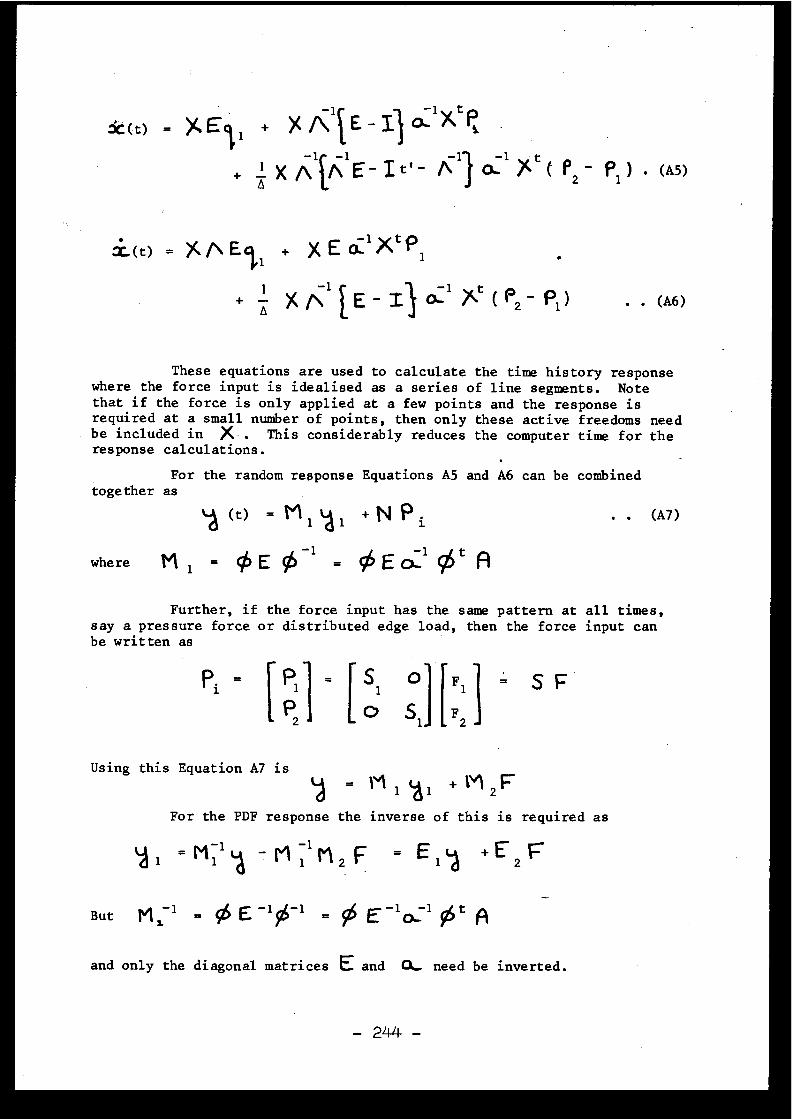
6t(t) = XE 1 + X A i E -0. 1 V tP,
-1[ -1
-
-
.+ Q X A A E- I t' - / 11 O+ 1 )(t ( P2
.(t) = )(AEI, + X E O ' Xt P ,
1+ Q X n 1 E -
Q1 xt ( P2 - P1 )
. . (A6)
These equations are used to calculate the time history respons ewhere the force input is idealised as a series of line segments . Notethat if the force is only applied at a few points and the response i srequired at a small number of points, then only these active freedoms nee dbe included in X- . This considerably reduces the computer time for th eresponse calculations .
For the random response Equations A5 and A6 can be combinedtogether as
~-1 (t) = M 1 LA I + N P i
. . (A7 )
where M 1 =
E 96 -1 = ~ E 0:1 0t^
Further, if the force input has the same pattern at all times ,say a pressure force or distributed edge load, then the force input ca nbe written as
Pi =
P1 = S1
F 1
S F
P
Ic S1 F2
al =M 1 1
- M 1 11 2 F = E 1 4 +E 2
But M 1 1 = $ E - 154-1 = may( E -10. 1 95t A
and only the diagonal matrices E and 0. need be inverted .
. (A5 )
Using this Equation A7 is= M 1 1.~ 1 + M 2 F
For the PDF response the inverse of this is required a s
- 244 -

Discussions
J .V . PARKER, United Kingdom
The technique presented here sounds very promisingindeed . Can you confirm that the eigenvalues calculated ar ethe complex ones and include the effect of damping ?
D .HITCHINGS, United Kingdom
Yes, the eigenvalues and vectors are usually complex .For the lower nodes the damping factors are usually at leas t50-60 % and for some combinations of soil/rock layers theycan be greater than 100 % . The general damped eigenvalu eproblem must be solved for the non-radiating boundaries .
J .V . PARKER, United Kingdom
What type of elements are used in the finite elementidealization ? Are they four node elements or do they havemidside nodes ?
D.HITCHINGS, United Kingdom
The simple four node linear interpolation elementwas used here although higher order and axisymmetrïc elementshave also been used .
J .V . PARKER, United Kingdom
What is the size of the problems you have considere din terms of number of degrees of freedom ?
D . HITCHINGS, United Kingdom
The largest problem so far run with the non-reflectin gboundaries is of the order of 140 degrees of freedom .
J .R . HALL, United State s
How can the wave transmission characteristics of afinite element mesh be influenced by the boundary conditionsof the model ?
D .HITCHINGS, United Kingdom
The boundary condition is that any outgoing wave i snot reflected by the arbitrary internal boundaries . For aplane wave this corresponds exactly to having a distribute dedge damping element which exactly absorbs the energy in th eoutgoing wave . Hence the boundary condition is part of th edynamic model . It turns out that the correct edge dampin g(the kinematically equivalent damping) gives a model whichhas a transfer function which is almost flat up to the )4 wavein an element cut-off frequency .
J .L . ZEMAN, Austria
A few remarks, which, as I do hope, will be takenup in the discussion at the end of this session : I am gladyou brought the stochastic methods into the discussion .Yesterday, there has been much discussion about theprobability one should assign to the SSE, where, in my opinio nit is wrong to speak of probabilities . The OBE, on the othe rhand ; is defined in many countries in statistical terms, but ,as far as I know, only in Japan are stochastic methods usedfor the determination of the response of nuclear power plantcomponents, and even there only for components which are no trelevant with respect to safety .
Now the remarks : You state in your paper that th etime-history method gives less conservative results . That i swrong . In many cases it does not give conservative result sat all . In my opinion, the time-history method, unless usin ga sample of time-histories, is not an honest method at all .
Secondly, what you do calculate are the moments o fthe response . That is not the area where the difficult pro-blems are, they come afterwards . The moments may be calculatedusing your approach, the Markov vector approach (modellin gthe quake as a Markov vector process by filtering white nois eby means of a non-stationary filter) or any other well-know nmethods .
The problems which are with the present state o fknowledge the difficult ones, are to determine the firs tpassage problems (in connection with primary stresses) and th eproblems in connection with the number of level crossing s(for fatigue and ratcheting evaluations) . Up to now we d ohave only the bounds given by Shinozouka for the first pro-blem, and some improvements obtained by Grossmayer (presente dat the 3rd SMIRT Conference) .
What we need very badly at the moment are bette rdescriptions in statistical terms of quakes, if possible, i ndependence of epicentral distance, focal depth, different soi lcharacteristics, etc .

.D . HITCHINGS, United Kingdom
In the main I agree with these remarks especiallyabout the need for better data . I am sorry if I implied thatonly one time history should be used and would agree that th emore used the greater the confidence in the results . In factthe probabilistic approach described in the paper gives a ra-tional way of performing this averaging before the calculatio nand then finding the statistically average response to th ecorresponding force input . I have various reservations abou tresponse spectra methods, one being that in cases of highdamping as with the soil-structure model described the parti-cipation factor must include velocity as well as acceleratio ncomponents . The simplicity of the method which is its mainvirtue then starts to be lost .
Whilst asking for more time to comment upon thenumber of level crossings the method does give the mean squaredisplacement, mean square velocity and the co-variance betweenthese and, if I remember correctly, this is all that is requi -red for the crossing problem . But I would agree that there ar estill questions to be answered in this field .
M . LIVOLANT, France
Je n'ai pas bien compris à la lecture de votreexposé comment vous preniez en compte le contenu spectral d ela force dans votre méthode .
D . HITCHINGS, United Kingdom
The earthquake is essentially transient so that th ePDF specification is essentially a time history . The frequencycontent is implicit in the signal but not easily recovered .Essentially it would require using the PDF to calculate th ecorrelation and then performing a Fourier transform on this .The resulting spectral density would then be a function o ftime .
[4 .2]
EARTHQUAKE RESPONSE SPECTRA FOR NUCLEAR POWER PLANT SUSING GRAPHICAL METHOD S
b y
C .G . DuffBranch Hea d
Atomic Energy of Canada Limite dPower Projects
Sheridan Park Research Communit yMississauga, Ontario, Canada
INTRODUCTION ,
Smooth ground-response and floor-response spectra provide aconvenient means for determining the resultant motion of nuclear power -plant structures, and light equipment mounted thereon, when subject to aseismic disturbance . The graphical methods described herein are simple an dconvenient to use . They give results which are consistent with thos eproduced by modal analysis techniques involving earthquake time-historie swhich are closely matched to the chosen ground-response spectrum [1] .
DESIGN SEISMIC RESPONSE SPECTR A
Figure 1 is a set of velocity-normalized, smoothed ground -response (or structure-motion) spectra based on the study of Mohraz, Hal land Newmark [2] for 2% structure damping and 0 .1 g peak ground acceleration . .The ground motion parameters . shown are most suitable for a competent roc kfoundation . The response spectra for damping values other than 2% weredetermined using the AMPFAC program .
AMPFAC PROGRAM
This program was described in detail in Reference [1] . Basically ,ground motion is represented by a decaying sinusoid . The response of thestructure to such motion applied at its base is thus harmonic, building up
- 248 -
to a peak value corresponding to that of the chosen design response spectru mat each frequency . The rate of decay of the ground motion determines themaximum response of the structure . A pseudo ground-damping dg is thu sselected to give the desired structure response, initially for 2% structur edamping Os . With the same pseudo ground-damping value (one for each of th ethree regions of the spectrum ; displacement, velocity and acceleration), afull set of response spectra are produced for other values of structuredamping ranging from 0 to 20% .
The motion of the structure is similarly imparted to th eequipment, with its damping 0e, to determine its peak response . The time-histories of the ground, structure and equipment are shown in Figure 2 ,and the envelopes of peak responses in Figure 3 .
As the equipment is considered to be very light, compared to thestructure on which it is mounted, it is treated as being uncoupled, a sshown in the model of Figure 8 .
AMPLIFICATION FACTOR S
The ratio of the peak structure response to ground motion at agiven frequency is defined as the structure-to-ground amplification factor ,AFs/g, which varies with both frequency and structure damping . Figure 4is a plot of AFs/g versus pseudo ground-damping, From this graph, three pgvalues can be determined which give the same three amplification factors a sthose found from Figure 1, for a given value of O s , say 2% . Using thesethree values of pg, the amplification factors for other Os percentages ca nbe found, from which a full set of ground response spectra can then b econstructed .
Figure 5 is used for determining the peak ratio of equipmen tresponse to structure motion, which is defined as the equipment-to-structur eamplification factor AFe/s, varying with frequency, as well as wit hequipment, structure and pseudo-ground damping . Figure 5 is derived fromFigure 4 where AFs/g is changed to AFe/s, and Os is changed to pe . Thevalue of AFe/s = w/2 is taken from Figure 4, at the intersection of th eOs = 0% curve and
= 100%. This corresponds to
= 0% and O s
100% i nFigure 5, where thegdashed line shown would become horizontal .
The example given on Figure 5 is for Os = 5%, for which AFe/s canbe found directly for any value of 0e, using only a design respons espectrum, such as Figure 1 . The procedure is as follows :
- Assume AFe/s is for structure frequencies between about 3
and 7 Hz
- From Figure 1 AFs/g (Os = 0%) = 6 .28
AFs/g (O s = 5%) = 3 .04
- AFs/g (pg = 0%) _ 1
2 10 .0125
(for Os = 5%)20s
1
- Ss
AFs/g (0 = 0%)- AFe/s (Oe = 0%) = S
. AFs/g (g g = 0%)e
AFs/g (Os = 5%)
=3
:24 x 10 .0 = 20 . 70
- AFe/s = 20 .7 is located on the Be = 0% curve on Figure 5, andis joined by a straight line (dashed) to AFe/s = rr/2 at theleft-hand scale as shown .
- AFe/s values are found at the intersections of the dashed lin eand the curves for any chosen value of 0e . A maximum error of± 5% is claimed for this procedure, if suitable care is taken .
- This procedure may be repeated for other values of O s .
ENVELOPE RESPONSE SPECTRA
A set of envelope response spectra are given in Figure 6 forOs = 5% and Be = 0 .5% . The ground-motion and two structure-motion spectraare taken from Figure 1, all plotted against acceleration . The equipmentresponse-spectrum represents the peak response of a set of 0 .5% dampedequipment oscillators to the motion of the 5% damped structure . The valuesof AFe/s were calculated using AMPFAC, but can be determined from Figures 1and 5, as described above .
The response of the equipment beyond about 15 Hz should roll of frapidly toward ground-motion at the cut-off frequency at 33 Hz, as show non Figure 6, rather than continuing out beyond 100 Hz, as indicated by th edashed straight-line extension . The procedure for constructing the high-frequency equipment response portion of the spectrum is now given :
- Compute AFe/s for f = 33 Hz as follows ,
- AFs/g (for P s = 0% and 5%) = 1 .00 at 33 Hz
1 .00- AFe/s (Be = 0%) = T.Tg x 10 .0 = 10 .0 (as before )
- AFe/s for Be = 0 .5% from Figure 6 is 8 .42
- Equipment acceleration Ae at 33 Hz = As x AFe/s = 0 .1 x 8 .42= 0 .842 g (where As = 0 .1 g is the acceleration of th estructure with 5% damping at 33 Hz) .
- Plot equipment acceleration from 4 .76 g at 7 Hz to 0 .842 gat 33 Hz as a straight line on a log-log scale, as shown o nFigure 6 .
- Replot the above acceleration line on a linear-log scale ,as shown on Figure 7 .
- Draw a tangent from the curved line on Figure 7 to meet theground-motion line at 33 Hz, as shown . This tangent becomesthe final equipment high-frequency peak response envelop edown to the maximum acceleration of the structure at 0 .304 g .It is shown redrawn as a solid curve on the log-log plot ofFigure 6 .
MODAL ANALYSI S
A modal analysis was performed on the shear-frame structureshown in Figure 8, with the results given in Table I . The structureaccelerations were taken from Figure 1 for the three modal frequencies ,and the modal responses were combined by the root-sum-square method fo reach floor .
FLOOR ACCELERATIONS
The floor accelerations are plotted in Figure 9 . It is notedthat the minimum acceleration cannot fall below that of the ground motio nor 0 .1 g which occurs just above the base of the structure as shown .These accelerations represent the maximum that would be seen by rigi dequipment mounted at each level . Rigid equipment is that with a funda-mental frequency of at least 33 Hz .
EQUIPMENT MOTION SPECTRUM
A floor-response or equipment-motion spectrum for a singl edegree-of-freedom structure having a natural resonant frequency, fs, o f4 Hz is shown in Figure 10 .
Straight-line envelopes with acceleration maxima at 0 .100, 0 .304 ,0 .531 and 4 .76 g are taken from Figure 6 . They are, respectively, themaximum ground-motion, maximum 5% damped structure motion, 0 .5% dampedstructure-motion, and 0 .5% damped equipment-motion (where the equipment i smounted on the 5% damped structure and has any frequency over the ful lrange of 0 .1 to 100 Hz) .
The equipment response to the 5% damped structure, wit hfs = 4 Hz, is given by solid curves Aeg and Aes . Aes and A'es are foundusing SPECEQ [3J for a range of equipment frequencies between 0 .4 and 40 Hzfor motion imparted by the structure at its resonant frequency of 4 Hz . Atvery high equipment frequencies, the equipment response falls to th emaximum structure acceleration As s = 0 .304 g ; since at such frequencies th eequipment acts as a rigid extension of the structure and picks up structur emotion with no relative movement of the equipment . At very low frequencies ,the equipment response to the structure A ' es falls toward zero .
In addition to the equipment amplifying structure motion, it als oamplifies ground-motion directly, especially at the lower frequencies . Thi sis shown by dashed curve A ' eg, also produced by SPECEQ, for fe and fg i nresonance (where fe and fg are equipment frequency and ground frequency
respectively), while fs remains constant at 4 Hz . At very low equipmentfrequencies, the equipment response falls to the maximum acceleration i twould see if it were resting directly on the ground ; since, at very lowfrequencies, the structure acts as a rigid extension of the ground . Thi slow-frequency equipment acceleration is 0 .531 g, which is the maximumacceleration As e of a structure with the same 0 .5% damping as theequipment . It applies only if the structure response to ground-motionremains constant down to the very lowest equipment frequencies . In fact ,the structure response As e falls off below about 3 Hz, so the equipmen tresponse must also fall off along solid line Aeg, becoming asymptotic t oAse as fe approaches zero .
It is significant to note that curve A ' eg can be approximate dfrom curve A ' es, and final curve Aeg can be produced directly from curv eA'eg as follows :
A' eg
A'es + Ase (peak) = A ' es + 0 .531 (always conservative) u pto fe/fs = 0 .9, above which A ' eg•ov A' es . With a slight modification to th eshape of A' es ,
A'eg = $' A ' es 2 + Ase (peak)
This is a more convenient relationship, as it holds over nearly the ful lrange of frequency ratios fe/fs from 0 to ow 0 .95 and suits the RSS (root -sum-square) modal-response combination method discussed below .
Aeg
= A ' eg
Ase (peak )
This expression, in effect, normalizes A'eg to unit response at fe = 0and then modifies the shape of the curve to Aeg which follows the slope ofAse, to which it becomes asymptotic at very low values of fe .
The final equipment motion spectrum is the solid curve Ae g(for fe/fs < 1 .0) and Aes (for fe/fs 5 1 .0) . The peak equipment amplifi-cation factor AFe/s = Aes (peak) / Ass = 4 .76/0 .304 = 15 .7 at fe/fs Fv 1 .0 .
EQUIPMENT AMPLIFICATION CURVE S
A set of equipment amplification curves is shown in Figure 11 fo ra range of frequency ratios fe/fs of 0 to 1 .8 and for several equipment/structure amplification factors AFe/s, ranging from 2 to 25 . For othe rvalues of AFe/s, the curves can be interpolated . For AFe/s > 25, theuppermost curve can be extrapolated by parallel lines to the desired pea kvalue . For fe/fs = 1 .8 to 10, AFe/s values can be found from Table II .AFe/s reaches 1 .000 at fe/fs = co and falls to 0 at fe/fs = O .
As e (@ fe)
The equipment amplification curves and table were developed froma modified version of SPECEQ [3] for transient response for a range o fpossible pseudo-ground, structure and equipment damping values giving thepeak amplification factors shown . The shape of any curve plotted wil lenvelope the curves produced for any likely combination of damping valuesgiving the same peak response . The peak response desired, for a .givenground-structure-equipment damping combination, is found from AMPFAC usin gFigure 5, as described above .
,The peak AFe/s values are found at frequency ratios fe/fs clos eto 1 .0, although at low peak amplification factors (generally for hig hstructure-equipment damping), the peak response will appear at frequenc yratios greater than fe/fs = 1 .0, as can be seen for AFe/s = 2 and 5 onFigure 11 .
The shapes of the equipment amplification curves of Figure 1 1have been adjusted in the range fe/fs = 0 to 1 .0, so that the ground -response portion of the equipment-motion spectrum, A'eg, can be found bythe RSS method given above .
FLOOR RESPONSE SPECTRA ,
While Figure 10 is for a single degree-of-freedom structure o rfor an equivalent structure in a given mode, equipment-motion or floor -response spectra can be derived for any number of modes of the structure ;using the method described above and the following detailed procedure .
For each structure mode n at a given floor level, for a give nequipment frequency fe, and for a given equipment damping Pe :
(1) Find ratio fe/fs n
(2) For fe/fsn > 1 . 0
Aesn = (As sn • AFe/s • l'sn • osn)
Where :
Aesn
acceleration of the equipment at fe, fo rstructure mode n, where equipment amplifie sstructure motion at fe/fsn 5 1 . 0
As sn = peak acceleration of structure in mode n ,at structure frequency fsn, taken fro mdesign response spectrum for given structuredamping O s
- 253 -
AFe/s = amplification factor of equipment-to-structure at fe/fsn from Figure 11 .Where peak AFe/s is determined for give nstructure and equipment damping fro mFigure 5, with suitable adjustment in th ehigh frequency region per Figures 6 and 7 .
rsn
= participation factor of structure fo rmode n
E Msi •1 sni
s (taken for all floors)E Ms i • 0sn i
Msi
= mass of structure at each floor, i
0sni
= shape factor (eigenvector) for structur ein mode n at point of equipment suppor tat given floor level i(taken for al lfloors when determining participatio nfactor)
rsn •osn = modal response factor (absolute value )
(3) For fe/fsn < 1 .0
A' esn12
(As e • rsn • 0sn) 2Aegn = + /"Ase •
J + N
2
2=
A"esn 2 + A' se n
Where :
Aegn
= acceleration of the equipment at fe, fo rstructure in mode n, where equipmen tamplifies ground-motion at fe/fsn < 1 . 0
= acceleration of equipment, behaving as astructure at frequency fe, taken fro mdesign response spectrum for structur ehaving damping of equipment B e
= peak acceleration of equipment, behavin gas a structure in mode n, at structur efrequency fsn, taken from design respons espectrum for structure having damping o fequipment B e
As en
E (I'sn • 0sn)n= i
Ase
Asen
- 254 -
A ' esn = (As sn . AFe/s • rsn • 0sn)
Where :
A ' esn = acceleration of the equipment at fe, fo rstructure in mode n, where equipmen tamplifies structure motion at fe/fs n< 1 . 0(Note : Symbols in brackets are asdefined under (2) above . )
N
E (rsn • 0sn) 2 = the sum of the squares of all then=i
structure modes n = 1 to N applying tothe given floor level .(Note : This factor is the square o f
Er0 given in Table I . )RS S
(4) The above is repeated for all the significant modes of th estructure, at the given equipment frequency, f e
Ae = il E Aesn2 + E Aegn2
Where :
Ae = the total equipment motion for the give nfloor level at a given equipment frequenc yby the RSS method of summation .
(5) Repeat the above for a number of equipment frequencies, fe ,including those which coincide with all the structure moda lfrequencies, fsn, being considered, as well as nearb yfrequencies .
(6) Repeat the above for as many other values of equipmen tdamping Pe as desired .
(7) Repeat the above for all other levels of the structure wher efloor-response or equipment-motion spectra are desired .
Notes on Procedure
(a)
When the floor acceleration falls to that of the ground or lowe r
(see Figure 9), the minimum floor-response spectrum becomes that o fthe equipment response to the ground-motion, taken directly from th edesign-response spectrum for a structure having the same damping asthe equipment . This, of course, applies to very low levels in th estructure, well below the first floor in the example given (se eFigure 8) .
(b)
Simplifications to the modal combinations described above, whic hgive adequate results (generally conservative) are as follows :
- For equipment frequencies up to_that of the first mode(fe < fsi) :
AsAe a J E A'esn2 + As2 .
e
el
Ase i
Where As e1 is as defined above for n = 1 or fe = fs i
- For equipment frequencies between that of the first mode 1and the last mode N (fsi
fe < fsN) :
Ae
E A'esn2 + E Aesn2 + Ase
- For equipment frequencies at or above that of the las tmode N (fe > fsN) :
Ae =
(c)
For closely-spaced modes (i .e . for frequencies Z5% apart), theabsolute sum of the modal responses should be taken before squarin gand adding to the squares of the other modal responses in Equation (4)above .
EXAMPLE OF METHO D
An example of the above method is given in Table Ill for th ethird (top) floor of the structure shown in Figure 8 . The resulting floor -response spectrum for equipment with 0 .5% damping is given in Figure 12 .Only the first two modes show prominent peaks, since the modal respons efactor for the third mode is very small . For design purposes, the peak sare broadened by ± 10% of the modal frequencies, and an envelope i sconstructed around the calculated spectrum, including raising the valle ybetween the first and second modes and broadening it by + 10% as above .This caters for possible errors in the determination of structure an dequipment natural frequencies and provides additional conservatism .
EARTHQUAKE TIME-HISTORY ANALYSI S
A time-history modal computer analysis was performed on th estructure of Figure 8 using the El Centro California earthquake of 1940(N-S), scaled to 0 .1 g peak acceleration . The amplified responses o flight equipment mounted on the top floor of the structure were determine d
- 256 -
using a modified form of SPECEQ [3], where the various modal response swere integrated numerically by computer . The resulting floor-respons espectrum is given in Figure 13 .
It is seen that the general shape of the spectra, Figures 12 an d13, are comparable, except that the heights of peaks and valleys differ .This is partly explained by the irregular nature of the El Centro equipmen tpeak motion, as applied to Figure 13, when compared with the smoot henvelope used for developing Figure 12 . The two equipment acceleratio nenvelopes are compared on Figure 14 .
Table IV compares the time-history analysis with the propose dgraphical method for the El Centro earthquake data . The variations in thepeak responses at 0 .5, 3 .0, 6 .54, 9 .54 and 20 Hz show that the RSS metho dis well within the expected accuracy when compared with the time-histor ymethod . The greatest discrepancy appears at the valley between the modes(5 .0 Hz) where the equipment-response is at a minimum . Similarly, a t2 .0 Hz, which is well below the first modal frequency, there is aconsiderable discrepancy between the RSS and time-history results . Fo rthese two cases, the absolute sum of the modal responses (including al lcomponents thereof) is shown in Table IV for comparison with the RSS values .As might be expected, the absolute sum gives slightly conservative results .
DISCUSSION
The graphical method for producing a floor-response spectrum i scomparable with that developed by computer using a real earthquake time-history . Only in particular regions of low equipment-response are ther esignificant discrepancies between the two approaches . While this can becorrected by combining the modal responses in selected areas by absolut esum, rather than by the RSS method proposed, the peak-valley broadenin gand spectrum-enveloping technique shown in Figure 12 is preferred (se eFootnote) .
It should also be noted that the time-history computer analysi scan readily miss the peak responses, because they occur at such precis efrequencies . This suggests that the chance of a real earthquake producin gthe maximum-possible responses in an actual structure, or in equipmen tmounted thereon, is very remote .
The proposed graphical method is similar to the approaches take nby Biggs [5] and Stoykovich [6] . Their techniques generally produce moreconservative results (sometimes excessive responses) and involve tediou sinterpolation procedures . The method proposed in this paper, using aground-response spectrum, is believed to give results which are mor econsistent with time-history analyses, where the earthquake time-history
Footnote : The problem of responses in the valley regions being higher tha npredicted by RSS modal analysis was observed in vibration test son actual structures in Japan [4] .
selected is compatible with the ground-response spectrum . The graphica lmethod is also amenable to computerization .
CONCLUSIONS
(a)
Ground-response or structure-motion spectra can be develope ddirectly from ground motion and a single response spectrum, usin guniversal graphical methods .
(b)
Floor-response or equipment-motion spectra can be develope ddirectly from ground-response spectra, again using graphica ltechniques .
.(c)
Sufficient conservatism can be applied to the floor-respons espectra, to ensure safe equipment design, by simple broadening -enveloping techniques .
(d)
The graphical method permits quick and convenient checks to b emade of expected peak responses, without performing a complete spectra l
analysis .
(e)
The method described in this paper is entirely deterministic ,apart from the choice of ground-motion, the single ground-respons espectrum selected and the probabilistic RSS treatment used fo rcombining modes .
(f)
While ground- and floor-response spectra can be determined b yhand, using a desk calculator, the method described in this paper i sadaptable to computer analysis at very low cost .
ACKNOWLEDGEMENT S
The valuable assistance given by S .S . Dua, G .G . Worthington an dMt Parnian is gratefully acknowledged .
a
- 258 -
REFERENCES
DUFF, C .G ., "Simplified Method for Development of EarthquakeGround and Floor Response Spectra for Nuclear Power Plant Design" ,Second Conference on Earthquake Engineering, McMaster University ,Hamilton, Ontario, Canada, 1-3 June 1975 .
NEWMARK, N .M ., "A Study of Vertical and Horizontal EarthquakeSpectra", WASH-1255, Directorate of Licensing, U .S . Atomic Energ yCommission, Washington, D .C . April 1973 .
NIGAM, N.C ., JENNINGS, P .C ., Computer Program "SPECEQ", A Digita lCalculation of Response Spectra from Strong-Motion Earthquak eRecords, NISEE Computer Applications, California Institute o fTechnology, Pasadena, California .
[4]
KONNO, T., KIMURA, E., "Earthquake Effects on Steel Towe rStructures Atop Building", Fifth World Conference on EarthquakeEngineering, Rome, 1973 .
[5]
BIGGS, J .M ., "Seismic Response Spectra for Equipment Design i nNuclear Power Plants", Proceedings of the First Internationa lConference -on Structural Mechanics in Reactor Technology, Vol . 5 ,Part K, Berlin, Germany, September 1972 .
[6]
STOYKOVICH, M ., "Methods of Determining Floor Design Respons eSpectra", ASCE-ASME Symposium, Pittsburgh, April 1972 .
[1 ]
[2]
[3]
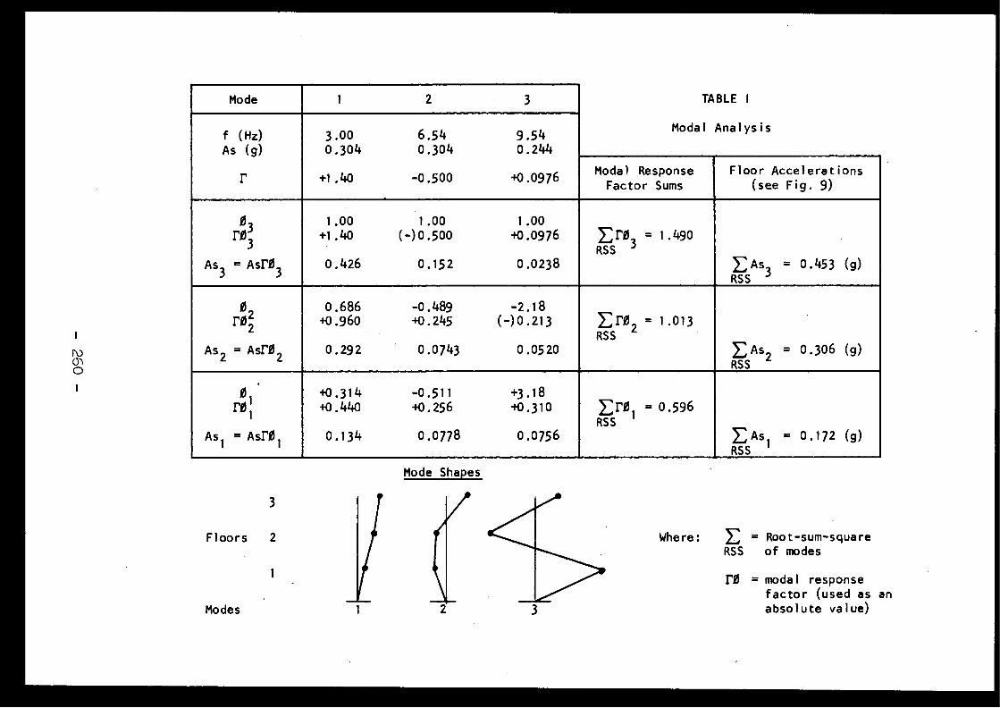
Mode 1
2
3 TABLE
I
f
(Hz) 3 .00
6 .54
9 .54 Modal Analysi s
As
(g) 0 .304
0 .304
0 .244
r +1 .40
-0 .500
i0,0976 Modal
Respons eFactor Sums
Floor Acceleration s(see Fig .
9)
1 .00
1 .00
1 .00r03 +1 .40
(-)o .500
+0 .0976 E r0
= 1 .4903 RSS
3
As
AsrO 0 .426
0 .152
0 .0238 E As
= 0 .453 (g)3
33
RSS
3
0 .686
-0 .489
-2 .1 8r02 +0 .960
+0 .245
(-) 0 .213 E rO 2 = 1 .01 3RS S
As 2 = Asr0 2 0 .292
0 .0743
0 .0520 EAs 2
= 0 .306 (g)RSS
0 +0 .314
-0 .511
+3 .1 8FO I +0 .440
+0 .256
+0 .310 ErO 1 = 0 .59 6RSS
As l
= Asr0 1 0 .134
0 .0778
0 .0756 E As 1
= 0 .172 (g)RSS
Mode Shapes
Where :
E = Root-sum-squareRSS of mode s
r0 = modal respons efactor (used as anabsolute value )2Modes
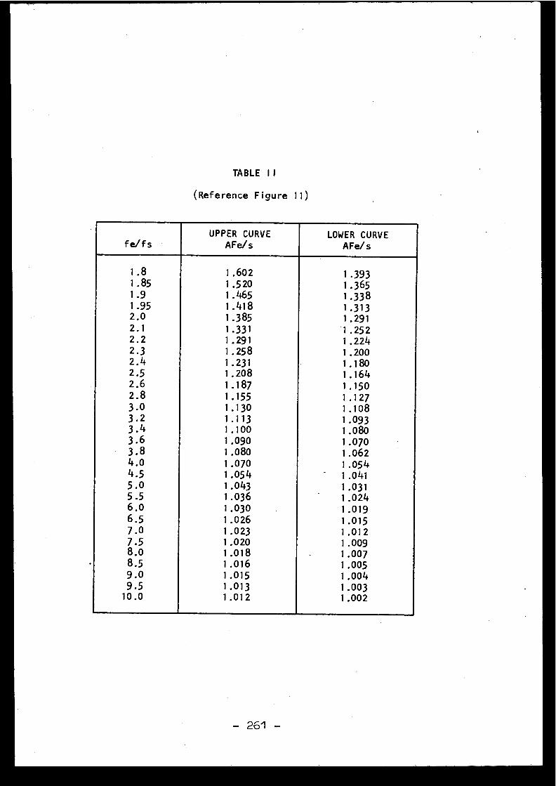
TABLE I I
(Reference Figure 11 )
fe/fsUPPER CURV E
AFe/sLOWER CURV E
AFe/ s
1 .8 1 .602 1 .3931 .85 1 .520 1 .3651 .9 1 .465 1 .33 81 .95 1 .418 1 .31 32 .0 1 .385 1 .29 12 .1 1 .331 1 .25 22 .2 1 .291 1 .2242 .3 1 .258 1 .2002 .4 1 .231 1 .1802 .5 1 .208 1 .1642 .6 1 .187 1 .15 02,8 1 .155 1 .1273 .0 1 .130 1 .10 83 .2 1 .113 1 .09 33 .4 1 .100 1 .0803 .6 1 .090 1 .0703 .8 1 .080 1 .0624 .0 1 .070 1 .05 44 .5 1 .054 -
1 .04 15 .0 1 .043 1 .03 15 .5 1 .036 1 .0246 .0 1 .030 1 .01 96 .5 1 .026 1 .01 57 .0 1 .023 1 .01 27 .5 1 .020 1 .0098 .0 1 .018 -
1 .0078 .5 1 .016 1 .0059 .0 1 .015 1 .0049 .5 1 .013 1 .00310 .0 1 .012 1 .002
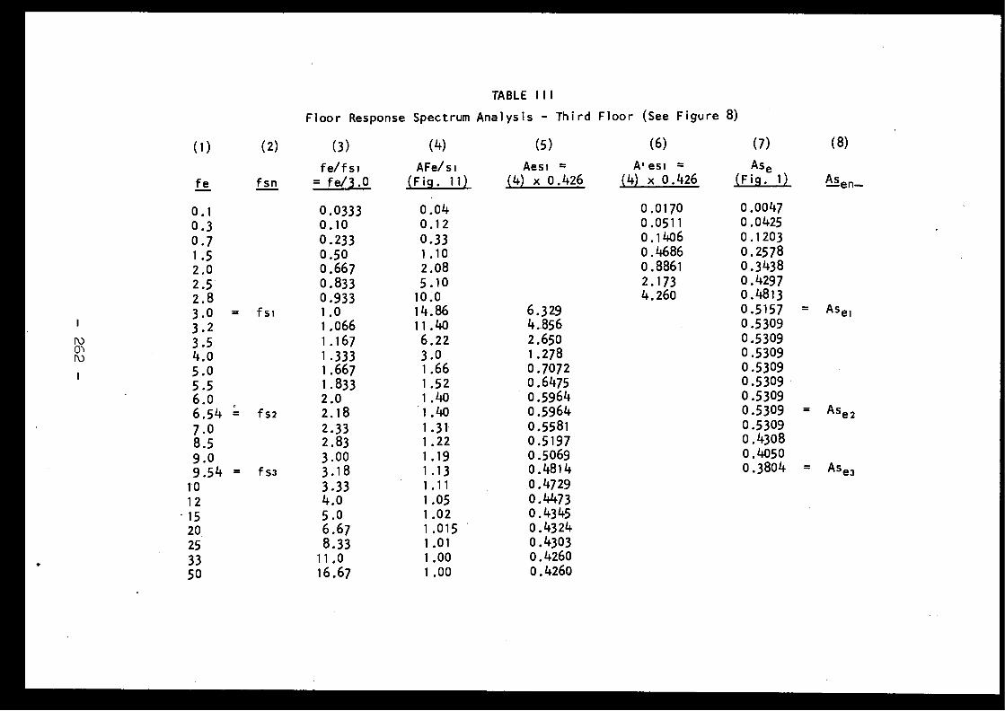
TABLE I I I
Floor Response Spectrum Analysis - Third Floor (See Figure 8 )
(1) (2) (3) (4) (5) (6) (7) (8 )
fe fsnfe/fs i
= fe/3 .0
AFe/s i(Fig .
11)Aesi
=
A'esi
= As e(Fig .
1) Asen-(4) x 0 .426
(4) x 0 .426
0 .1 0 .0333 0 .04 0 .0170 0 .0047
0 .3 0 .10 0 .12 0 .0511 0 .0425
0 .7 0 .233 0 .33 0 .1406 0 .120 3
1 .5 0 .50 1 .10 0 .4686 0 .257 8
2 .0 0 .667 2 .08 0 .8861 0 .343 8
2 .5 0 .833 5 .10 2 .173 0 .4297
2 .8 0 .933 10 .0 4 .260 0 .481 3
3 .0
= f si 1 .0 14 .86 6 .329 0 .5157
= Ase 1
3 .2 1 .066 11 .40 4 .856 0 .5309
3 .5 1 .167 6 .22 2 .650 0 .5309
4 .0 1 .333 3 .0 1 .278 0 .5309
5 .0 1 .667 1 .66 0 .7072 0 .53095 .5 1 .833 1 .52 0 .6475 0 .5309
6 .0 2 .0 1 .40 0 .5964 0 .5309
6 .54
= fs2 2 .18 1 .40 0 .5964 0 .5309
= As e2
7 .0 2 .33 1 .31 0 .5581 0 .5309
8 .5 2 .83 1 .22 0 .5197 0 .4308
9 .0 3 .00 1 .19 0 .5069 0 .4050
9 .54
= f s3 3 .18 1 .13 0 .4814 0 .3804
= Asea
10 3 .33 1 .11 0 .4729
12 4 .0 1 .05 0 .4473'15 5 .0 1 .02 0 .4345
20 6 .67 1,015 0 .4324
25 8 .33 1 .01 0 .4303
33 11 .0 1 .00 0 .4260
50 16 .67 1 .00 0 .4260
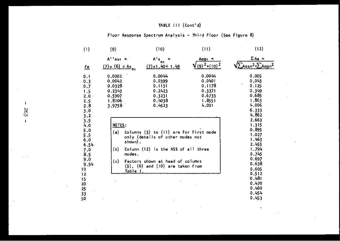
TABLE I l l (Coned)
Floor Response Spectrum Analysis - Third Floor (See Figure 8)
(10)
(11) (12 )
A''esi =
A's
=el
(7)x(6) -Asea
(7)xl .40+1 .49 EAe =
J/Aesn2++Aegn2fe
Aegi_
V(9) 2+(10) 2
0 .00440 .03990 .113 10 .24230 .323 10 .40380 .4523
0 .00440 .040 10 .117 80 .337 10 .67331 .855 14 .00 1
0 . 1
0 . 30 . 71 . 52 . 02 . 52 . 83 . 03 . 23 . 54 . 05 . 05 .56 . 06 .5 47 . 08 . 59 . 09 .5 4
1 01 21 52025
3350
0 .000 2 .0 .00420 .03280 .23430 .59071 .81063 .975 8
NOTES :
(a) Columns (3) to (11) are for first mod eonly (details of other modes no tshown) .
(b) Column (12) is the RSS of all threemodes .
(c) Factors shown at head of column s(5), (6) and (10) are taken fromTable 1 .
0 .0050 .0430 .1250 .3490 .6851 .8634 .0066 .3334 .8622 .6631 .31 50 .895
1 .0271 .4632 .4551 .7940 .7450 .6970 .63 80 .6050 .51 20 .48 10 .4700 .4600 .45 40 .453
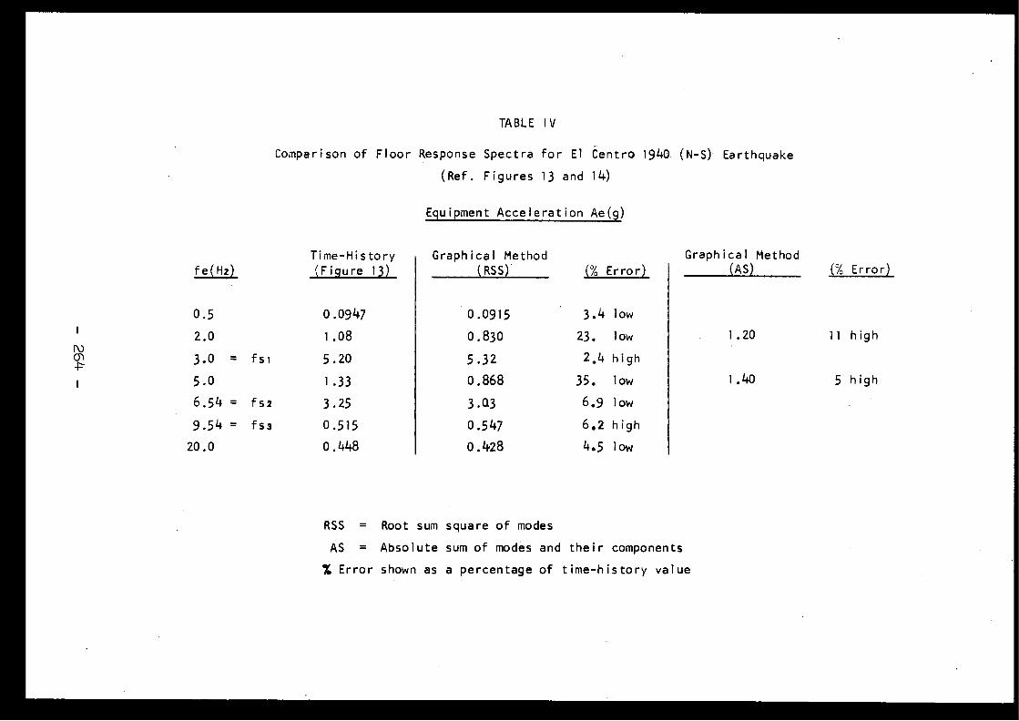
TABLE I V
Comparison of Floor Response Spectra for El Centro 1940 (N-S) Earthquake
(Ref . Figures 13 and 14)
Equipment Acceleration Ae(g )
fe(Hz)
Time-Histor y(Fiqure
13)Graphical
Method(RSS) (% Error)
Graphical
Metho d(AS) (% Error )
0 .5 0 .0947 0 .0915 3 .4
low
2 .0 1 .08 0 .830 23 .
low 1 .20 11 hig h
3 .0
= fsi 5 .20 5 .32 2 .4 high
5 .0 1 .33 0 .868 35 .
low 1 . 140 5 hig h
6 .54 = fs2 3 .25 3 .Q3 6 .9
low
9 .54 = fss 0 .515 0 .547 6 .2 hig h
20 .0 0 .448 0 .428 4 .5
low
RSS = Root sum square of mode s
AS = Absolute sum of modes and their component s
% Error shown as a percentage of time-history value
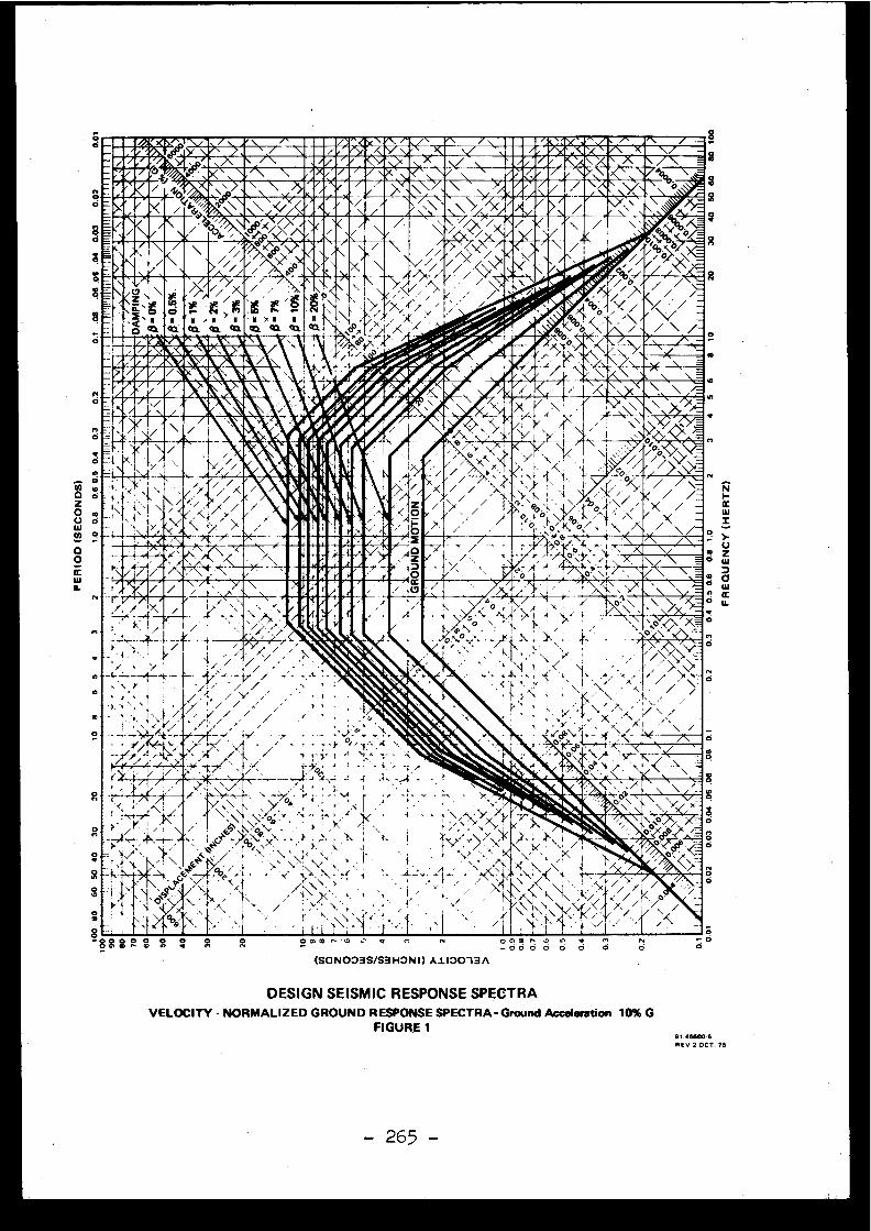
- •0000k.. 2m.A 1 nI►J91120.110 1)1LLv nr/9N~~IZtiA ~~:1~~COW 0. ~A ~~GGOSI311 OO.31 I~G/jr/~1►1~~~i72W 5OROMIlleellE41M
/~bb;y !fi \ \N
,/ 3im / - \\ -InIIIIN / 4JJ4 / f \ /\'
, k8' ,~i~ `~/ '
kn./ d'6~
i
k/ .l 1
1/ o\ E
/
\2,\ eoo/,c_
>Ç li"
/,/~~•~" ' • I`t:)'.r \/ / /
z, N , N
> N N} N
N N
I Q11\1/ ice/ !%~
xt,, '
co O3 C1. Ci Ol 01 <II 01 ,oPxf
O / /
,./t i%/~~~ ./•i ~i „tSOIS .A''WI ► À111 L
. .~ ►.`ice O 0 .L,; 6r/00, ~' !li11111K' r
'
I-'- SSIIMIMk-
t I /7 ~' / /N.x Y '\ ~`
\ . /
1,, } / /
t
S I O 'o
~,
O x>
.' %C
/
~_ .._ ô 6 MIMIIPMIICNMo
-r-., ryIla/ Ill • /
I cc
'(.,
1(i . -
_~ .
i .° oO
-1st ,I.'
.I
~ -
00
7
">~r-
-~--r _?L\' Ÿ\ . )' ô-r f-oe
-`ci'^-t -~ ^f" .~r~/ 1 .
x:
!'~` .. T
-.i.
- .~n-
• . /.,Fl.PG~(I_ \ 'Y` i~\ %~k, r4t
L. / NL.(
é1 I I r~rn~
/~~.,. 1 I I/T 'bt \Y\ /'I./\
o
8'88 m ° 8 8
H
o
o
.
ô(SONOO3S/S3H3NI) A1130131 \
O 0, 02 ., .7
Q
Cl
fV ô
o
no
o8
ON
OzO
ow
W
o
W
O
d
ON
o
o
8
C
o
wn
R R
DESIGN SEISMIC RESPONSE SPECTR AVELOCIT Y - NORMALIZE D GROUN D RESPONSE SPECTRA-Groun d Acceleration 10% G
FIGURE 1 91 .,5500-5RE V 2 OCT . 75
- 265 -
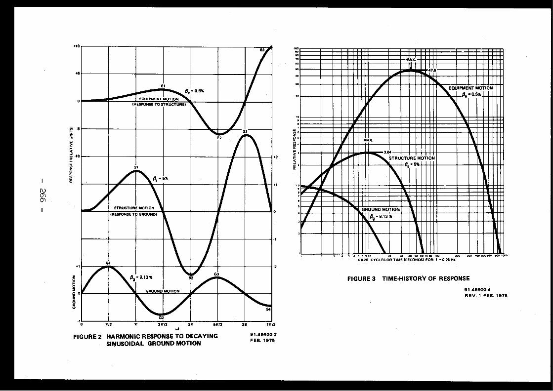
E 3
E1Oe = 0 .5%
EQUIPMENT MOTION(RESPONSE TO STRUCTURE)
E2
S3
Si
ft6 5%
STRUCTURE MOTION
(RESPONSE TO GROUND )
G1
=9.13 %
GROUND MOTION
S2G 3
G2
G4
6 7 8 9 10
20
30 40 50 60 10 80 100
200
300 400 500600 600 1000
X 0.25 CYCLES OR TIME (SECONDS! FOR f -0.25 Hs.
FIGURE 3 TIME-HISTORY OF RESPONS E
91 .45600- 4REV . 1 FEB . 197 5
20
0
2
+10
+5
0
+ 1
zOgO
O 0DOac~
-1
+2
+1
0
- 1
-2
37 71r/2
91 .45600-2FEB. 197 5
*
31x/2
21► -
57/2
FIGURE 2 HARMONIC RESPONSE TO DECAYIN GSINUSOIDAL GROUND MOTION
112
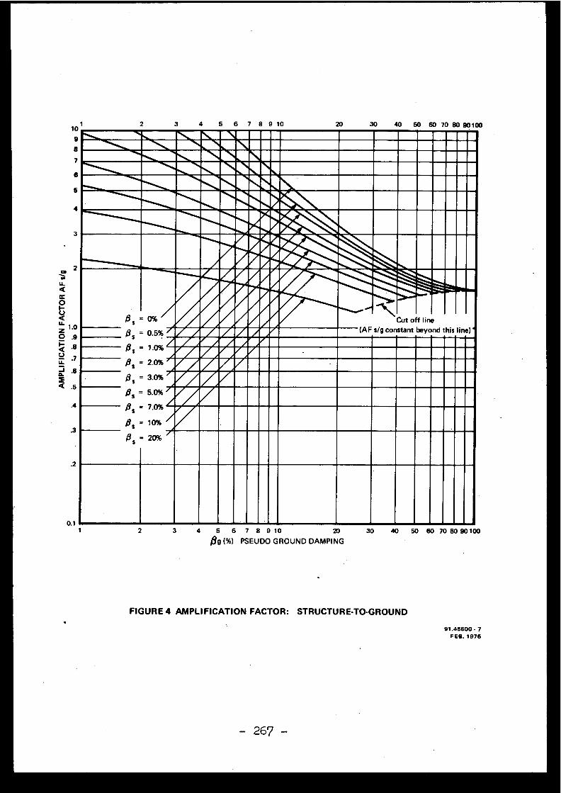
1 2 3
FIGURE 4 AMPLIFICATION FACTOR : STRUCTURE-TO-GROUND
91 .45600 . 7FEB . 1975
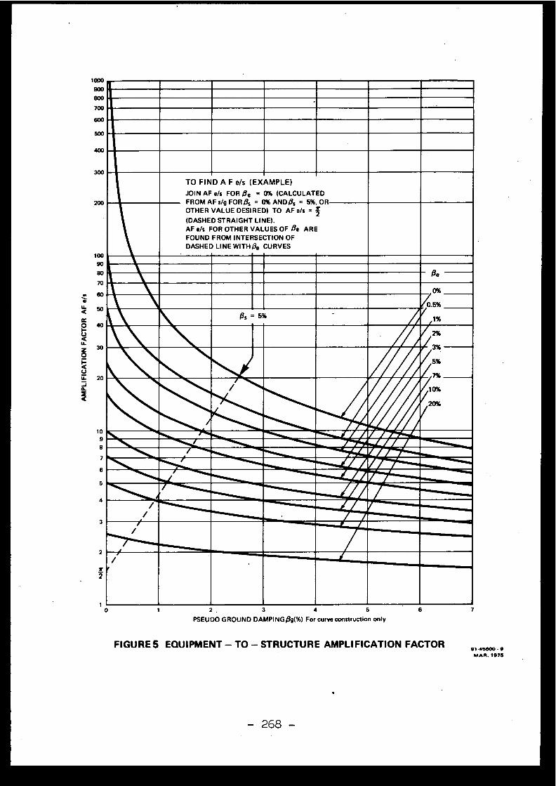
1900
800
700
60 0
50 0
40 0
300
top
TO FIND A F e/s (EXAMPLE )JOIN AF e/s FOR fie = 0% (CALCULATEDFROM AF VI; FOR Os = 0% AND as = 5%. O ROTHER VALUE DESIRED) TO AFe/s =
(DASHED STRAIGHT LINE) .AF e/s FOR OTHER VALUES OF Oe AR EFOUND FROM INTERSECTION O FDASHED LINE WITH/3e CURVE S
19000
80 - Qe70
~' ' 096
0.5%
1 %
50
l40 1, Ss=5%
LllknMn30
VIH,10%
20%
20
10
4 `
89~_V~_~~►i~~~'/I
Filar7
6
/
/
''"•01alIA-
~ffa ►
7r
_
0
2 .
3
4
5
6
7PSEUDO GROUND DAMPING A(%) For curve construction onl y
FIGURE 5 EQUIPMENT - TO - STRUCTURE AMPLIFICATION FACTOR91 . 45600 - 9
MAR . 1976
- 268 -
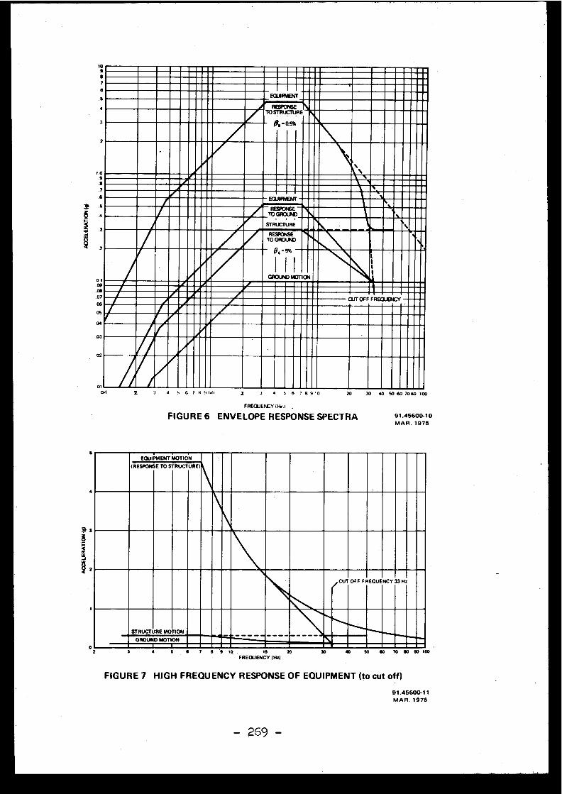
6
3
2
2
010a 4
6 7 H 11141 2 3
4
5 6 7 6 910 20 30 40 50 60 7080 100
FREQUENCY 11-le.r .
FIGURE 6 ENVELOPE RESPONSE SPECTR A
6
EQUIPMENT MOTION
IRESPONS E TO ST RUCTUREI
91 .45600-1 0MAR . 1975
02
4
3
STRUCTURE MOTIO N
GROUND MOTION
4 5 7 30 40 50
FIGURE 7 HIGH FREQUENCY RESPONSE OF EQUIPMENT (to cut off )
91 .45600-1 1MAR . 197 5
- 269 -
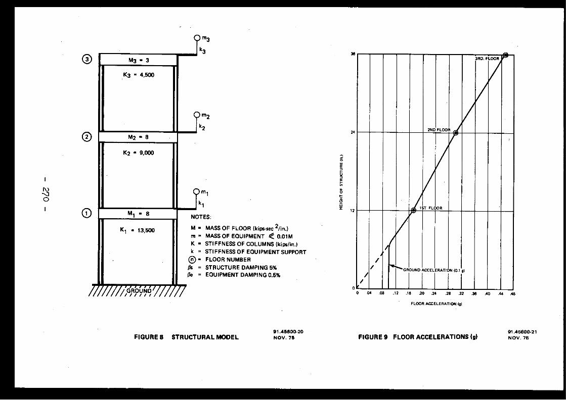
M3- 3
= 4,500
M 2 = 8
= 9,000
m 1
k 1
NOTES :
M = MASS OF FLOOR (kips-sec 2/in . )m = MASS OF EQUIPMENT < 0.01 MK = STIFFNESS OF COLUMNS (kips/in . )k = STIFFNESS OF EQUIPMENT SUPPORT
On = FLOOR NUMBE RQs = STRUCTURE DAMPING 5%(ie = EQUIPMENT DAMPING 0 .5%
M 1 = 8
K 1 = 13,500
///~GRÔÛND /// ///
/GROUND ACCELERATION (0 .1 g )
0
.04
.08
.12
.18
.20
.24
.28
.32
.36
.40
.44
.48
FLOOR ACCELERATION (g )
24
12
//
/o/
91 .45600-20FIGURE 8 STRUCTURAL MODEL
NOV. 7591 .45600-2 1
FIGURE 9 FLOOR ACCELERATIONS (g)
NOV . 75
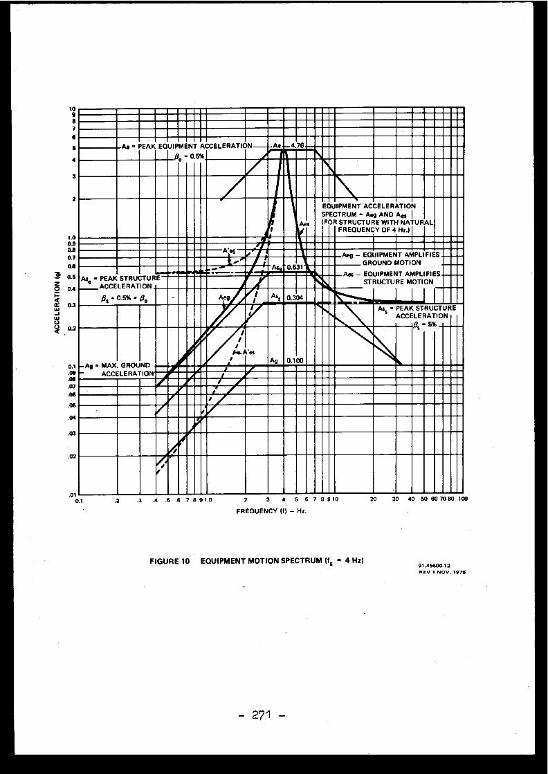
Ae = PEAK EQUIPMENT ACCELERATION Ae.._4.76~tie = 0.5%
Aes
EQUIPMENTSPECTRU M(FOR
ACCELERATION= Aeg AND Aes
STRUCTURE WITH NATURALFREQUENCY OF 4 Hz . )
AIS wig Aeg - EQUIPMEN TGROUND
Aes - EQUIPMENTSTRUCTUR E
MOTIONAMPLIFIES
AMPLIFIESMOTION
~ERWAN.111111, ~Ase =PEAK
ACCELERATIO N0.5% =
STRUCTUR E
Qe
" .
Ass 0.304 =/3s =
Ass = PEAKACCELERATION
STRUCTUR E
~s =5%
-Ag =MAX.-
ACCELERATIO NGROUND
A Ag 0 .100~/~~,-r
i.01
0.1 .3 30 40 50 60 70 80 10020.2 2
3
4 5 6 7 8 91 0.4
.5 .6 .7 .8 .9 1 . 0
3
2
1 .00.90.80.70.60 .5
zO 0 .4I-CCC 0.3WJWU
0. 2
0. 1.0 9.06.0 7.06.0 5.0 4
.03
.02
FREQUENCY (f) - Hz .
FIGURE 10 EQUIPMENT MOTION SPECTRUM Ifs = 4 Hz)91 .45600-1 2REV 1 NOV. 1975
271 -
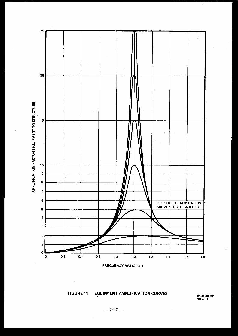
1 5
1 0
25
20
(FOR FREQUENCY RATIOSABOVE 1 .8, SEE TABLE II I
0 .2
0.4
0.6
0 .8
1 .0
1 .2
1 .4
1 .6
1 . 8
FREQUENCY RATIO fe/fs
FIGURE 11 EQUIPMENT AMPLIFICATION CURVES
- 272 -
91 .45600-2 2NOV . 75
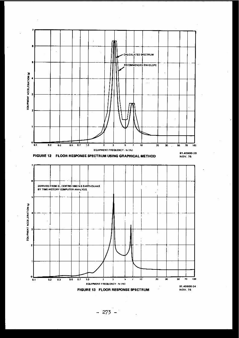
CALCULATED SPECTRU M
RECOMMENDED ENVELOPE
ww
0 ee>_.illIn rlfa®0.1
0 .2
0.3
0.5
0 .7
1 .0 2
3
5
7
10 20
30 .
50
70
100
EQUIPMENT FREQUENCY • fe (Hz)
FIGURE 12 FLOOR RESPONSE SPECTRUM USING GRAPHICAL METHO D
DERIVED FROM EL CENTRO 1940 NS EARTHQUAK EBY TIME-HISTORY COMPUTER ANALYSIS.
11 IIIM I I 1 11
- 273 -
91 .45600-23
NOV . 7 5
00.1
0.2
0.3
0.5
0. 7
FIGURE 13 FLOOR RESPONSE SPECTRU M
1 .0
2
3
5
7
10
20
30
50
70
100
EQUIPMENT FREQUENCY - to (Hz)91 .45600-2 4
NOV . 75
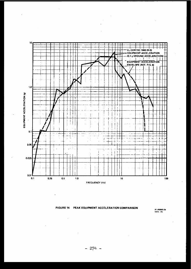
1 0
1 . 0
0. 1
0 .05
0.025
(0.1
GROUND
194 0ACCELERATION
(N-S)
ACCELERATION)=
--
r.. EL CENTR Or qe EQUIPMENT
_ w .c-
i~ I g
„' P EQUIPMEN TENVELOPE (REF .
ACCELERATIONFIG .6)
I I1
I 1 ,
milWaIMI1IMMIT111MIlm
-r-i-
__-n L t
! fi----~- ~
I -t -I
-t
_
I-1
- _ \IIr-f-~- -
_~
. . .1 __-.
I~I
' .
t . .~y_1. .
• ~1
I
1
0.25
0 .5
1 .0
10
100
FREQUENCY (Hz )
FIGURE 14 PEAK EQUIPMENT ACCELERATION COMPARISON91 .4560625NOV . 7 5
- 274 -
Discussions
J .L . ZEMAN, Austri a
One remark to the figures given in the comparison .In comparing ground floor and top floor response spectra fo rsix different time histories for the excitation, time historie swhich match the same given ground response spectrum, we founddifferences of about 5 % for the absolute maximum of the res -ponse curve and over 30 % for the second maximum, if there wa sany, and, astonishingly, 10-15 % for the rigid body portio nof the response curve . So, the differences just shown in thi spresentation are of about the same size as between differen ttime histories results .
J .V . PARKER, United Kingdom
Is the response spectrum shown in Figure 13 smoothed ?
C .G . DUFF, Canada
Only to the extent that a limited number of frequen -cy points were selected and the responses at these frequencie swere joined with a smooth curve . Actually, about 30 point swere selected, with an additional 10 points close to theexpected 3 modal frequencies . It should be noted that in orde rto achieve peak response for the three modes, frequencies hadto be determined to five decimal places (i .e . 6 significantfigures) . This suggests that peak responses can easily b emissed in practice .
D . COSTES, Franc e
La méthode présentée s'applique-t-elle aux mouve-ments verticaux ? Obtient-on des amplifications aussi élevées ?
C .G . DUFF, Canad a
The method presented was for a single horizontaldirection but can be applied equally to the other horizontaldirection and the vertical direction . In actual applications ,the .vertical responses are found in a similar way, althoughthe modal frequencies are, understandably, different . Also ,the vertical ground response spectra that we use are scale dto 2/3 of the horizontal spectra .
[ 4 .3 ]
METHODES USUELLES D'ANALYSE SISMIQUE DES CENTRALESOBTENTION DIRECTE DES SPECTRES DE PLANCHERAPPLICATION A UNE CENTRALE A NEUTRONS RAPIDES
ET UNE CENTRALE A EAU PRESSURISEE
M .Livolant et F .Jeanpierre - Commissariat à l'Energie AtomiqueCEN-Saclay- Gif sur Yvette (France )
La donnée de base pour l'analyse de la tenue des réacteurs nu-cléaires aux séismes est le spectre de sol . A partir de cett edonnée on utilise essentiellement deux méthodes pour effectue rl'analyse sismique : la méthode dynamique directe, et la métho-de spectrale . La méthode dynamique directe consiste à calcule rpar résolution numérique des équations en fonction du temps ,le mouvement des différents points, et les contraintes en ré-ponse à un ou plusieurs accélérogrammes représentant le mieu xpossible les spectres de sol . Cette méthode peut être utiliséelorsque le comportement des structures devient non linéaire ,par contre,elle est relativement lourde et peut étre coûteuse .La méthode spectrale utilise le spectre de sol pour obteni rl'amplitude des modes propres des structures . Une méthode d'ob-tention directe des spectres de plancher à partir des spectre sde sol est
présentée et appliquée à deux types de réacteur .
The basic data for seismic analysis of nuclear reactor is theground response spectrum . Frain this spectrum two methods ar eincurrent use for the seismic analysis the direct time inte-gration and the response spectrum method . In the direct timeintegration one resolves the motion equations and calculate sthe displacements and the stresses for one or many accelero-gramms representing as well as possible the ground spectrum .Such a method can be used in non linear analysis but appearsuneasy and expensive in computing time . The response spectrummethod calculates the eingen vector amplitudes . In the pape ra direct method of floor spectrùm calculation from the groundspectrum is presented and applied to two different nuclearpower plants .
-276 -
I-INTRODUCTION
Les données de base pour l'analyse sismique des struc-
tures sont les spectres de sol,généralement fournis sous l aforme suivante :
-Une accélération horizontale maximum de référence Y 0
-Une famille de courbes Au (v) d'amplification horizontale ,normalisées à une accélé ation horizontale maximu m - du so lunité, et correspondant à différentes valeurs de l'amor-tissement rédui t
-Une famille similaire de courbes AV(v) d'amplificationverticale,normalisées de la même façon à une accélératio nhorizontale unité .
Ces courbes d'amplification A(v) correspondent au ma-ximum de déplacement relatif durant le séisme d'un oscillateurharmonique à la fréquence v, .multiplié par v (spectre en pseu-do-vitesse) ou par v 2 ( Ar,(v) spectre en pseudo-accélération) .
La direction de l'accélération horizontale n'est pa sfixée . En fait,au cours du séisme, la direction du mouvement d usol est très variable, et il est raisonnable d'admettre qu el'accélération maximum est atteinte à un moment ou à un autr edans n'importe quelle direction .
L'accélération verticale maximum est généralement *con-sidérée comme inférieure à l'accélération horizontale (facteu rde réduction variant entre 1 pour les séismes lointains et 2/ 3pour les séismes proches) .
Suivant les pays, ces courbes d'amplification corres-pondent à l'amplification moyenne estimée au cours du séisme ,à une amplification moyenne plus un écart type, ou à une enve-loppe . Il est bien entendu nécessaire de tenir compte de ce sdifférentes définitions au niveau de l'analyse des contrainteset déplacements calculés .
De même ces définitions interviennent pour la sélec-tion d'accélérogrammes adaptés au site :à un spectre défini enmoyenne devra correspondre une famille d 'accélérogrammes ayantce spectre comme moyenne . A un spectre défini comme envelopp ecorrespondra une famille d'accélérogrammes dont l'enveloppe de sspectres est à toute fréquence supérieure ou égale au spectr ede référence .
A partir de ces données, l'analyse des mouvements e tde la tenue des structures s'effectue en trois étapes : étudede l'interaction sol-fondation, réponse du système principal ,incluant les effets de raideur et de masse du sol, réponse de ssous-systèmes connectés au système principal, mais dont la pris een compte dynamique n'est pas nécessaire au niveau de l'étud ede la réponse du système principal .
Les principales méthodes de calcul de réponse de sstructures à une sollicitation sismique sont la méthode quasi -statique, la méthode spectrale, et la méthode dynamique directe.
-2?7-
II- ANALYSE DE LA REPONSE DES STRUCTURES
Pour analyser la tenue d'une structure à un séisme,ilest nécessaire de savoir calculer,ou du moins estimer,le mou-vement de cette structure au cours du séisme . En pratique, onpeut toujours,pour formuler ce problème, se ramener à un sys-tème du type
KX + CX' + MX" =-MT' (t )
avec K matrice de rigidit éC matrice d'amortissementM matrice masseX vecteur déplacement relatif des différents points de
la structure (éventuellement rotation )r(t)vecteur correspondant à l'accélération du sol y(t )
reportée en tout point (ou le cas échéant à l'accé -lération du point de connexion du sous système su rle système principal) .
La détermination des points de la structure,le calcu ldes matrices de raideur K et masse M dépendent du type de sché-matisation choisi pour la structure . La méthode la plus simpl econsiste à décomposer la structure en systèmes masses-ressort scouplés ou non; les masses sont assez faciles à estimer, le sraideurs de ressorts sont plus délicates : on les détermine gé-néralement à partir de la déformation statique calculée ou es-timée, ou à partir de la connaissance de la première fréquenc epropre de vibration . La validité d'une telle schématisationdépend évidemment beaucoup du sens mécanique de l'utilisateur .Elle est surtout utilisée en génie sismique pour la tenue d'unbâtiment ou d'un ensemble de bâtiments .
Une méthode plus perfectionnée consiste à discrétise rles structures continues en un certain nombre de points . Le smatrices de rigidité et de masse correspondantes sont alorsobtenues par des méthodes type éléments finis,adaptées à l agéométrie à traiter : éléments finis de poutre, de coques ou demassifs .
La matrice d'amortissement est généralement très ma lconnue . On se contente souvent de déterminer ses coefficient spar des considérations empiriques .
Naturellement il faut adapter la précision de l'ana-lyse sismique à l'importance de la structure étudiée du poin tde vue fonctionnement et du point de vue sécurité . Les troisméthodes présentées ci-après, par ordre de complexité crois-
. sante,permettent ces différents niveaux d'analyse .
II-1 Méthode quasi statique
Soit X la déformée statique de la structure sous l'ac-tion de l'accélération y de référence dans la direction OX, e tv la première fréquence°propre de la structure dans cette di-rection . Compte tenu de l'amplification A(v ) fournie à cett efréquence par le spectre moyen d'oscillateurs pour l'amortis-sement estimé, on a approximativement :
- 278 -
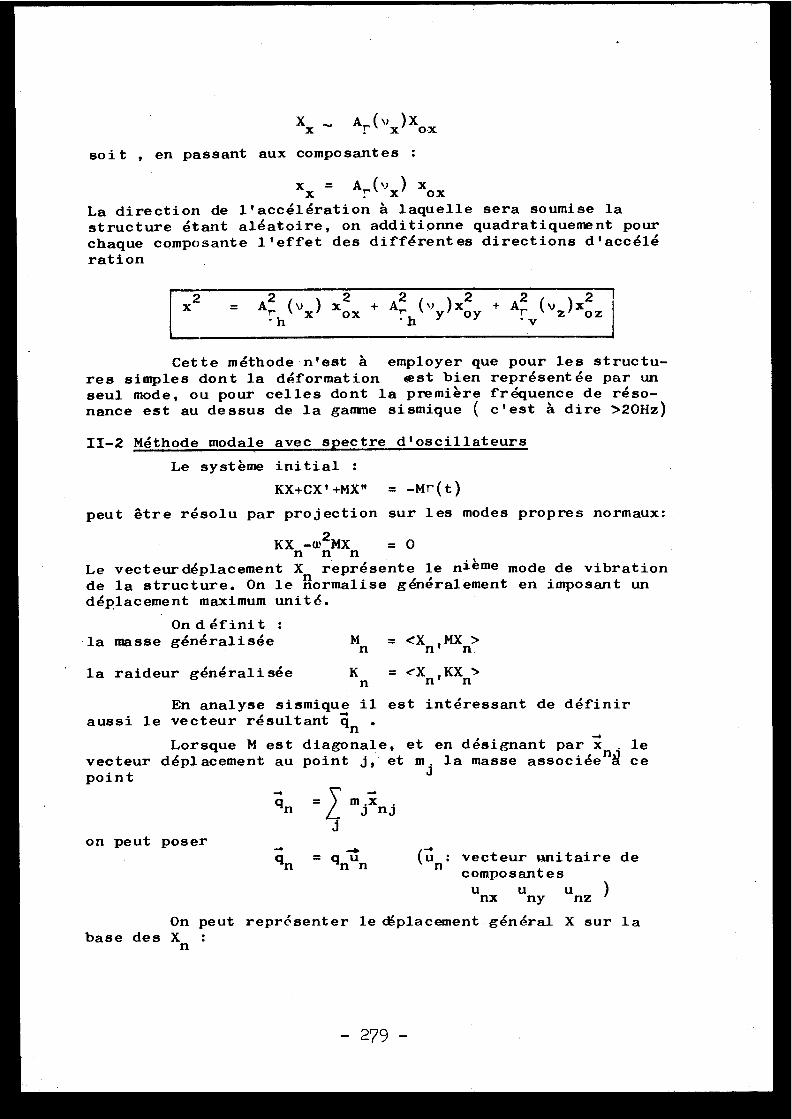
Xx
A,. ("x )Xox
soit , en passant aux composantes :
xx
Ar(vX)xO X
La direction de l'accélération â laquelle sera soumise lastructure étant aléatoire, on additionne quadratiquement pou rchaque composante l'effet des différentes directions d'accél ération
12 =A2h(vx)
xox + A2h (vy )xoy +A2rv(vz
)x2-7
Cette méthode n'est â employer que pour les structu-res simples dont la déformation est bien représentée par unseul mode, ou pour celles dont la première fréquence de réso-nance est au dessus de la gamme sismique ( c'est â dire >20Hz )
II-2 Méthode modale avec spectre d'oscillateur s
Le système initial :
KX+CX'+MX" = -Mr(t )
peut être résolu par projection sur les modes propres normaux :
KX -w2 MX
= 0n n nLe vecteur déplacement X représente le nième mode de vibrationde la structure . On le normalise généralement en imposant undéplacement maximum unité .
On définit :la masse généralisée
Mn = <Xn' MXn>
la raideur généralisée
K = <X ,KXn
n n
En analyse sismique il est intéressant de défini raussi le vecteur résultant qn .
Lorsque M est diagonale, et en désignant par x l evecteur déplacement au point j, et m j la masse associé e n 1 c epoint
qn - mjxn j
J
qn
gnon
(ûn : vecteur wnitaire d ecomposante s
nx uny unz )
On peut représenter le céplacement général X sur l abase des Xn
on peut poser
u
-279 -
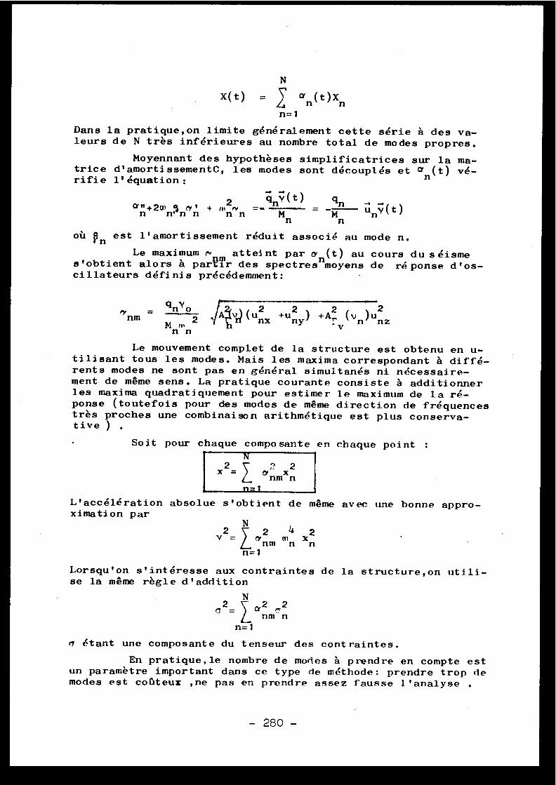
N
X(t)
Xan (t)Xn
n= 1
Dans la pratique,on limite généralement cette série à des va -leurs de N très inférieures au nombre total de modes propres .
Moyennant des hypothèses simplificatrices sur la ma -trice d'amortissementC, les modes sont découplés et an (t) vé-rifie l'équation :
2
q v ( t )ann+2wn4 nct~
n+ mn. n
Mn
qnM
unY( t )Mn
où Rn est l'amortissement réduit associé au mode n .
Le maximum r m atteint par o- n (t) au cours du séismes'obtient alors à parRir des spectres moyens de réponse d'os-cillateurs définis précédemment :
nm-
2~IA( 2unx +uny) +AZ ( `~n )unz
M n
' vn n
Le mouvement complet de la structure est obtenu en u -tilisant tous les modes . Mais les maxima correspondant à diffé -rents modes ne sont pas en général simultanés ni nécessaire -ment de même sens . La pratique courante consiste à additionne rles maxima quadratiquement pour estimer le maximum de la ré-ponse (toutefois pour des modes de même direction de fréquence strès proches une combinaison arithmétique est plus conserva-tive )
Soit pour chaque composante en chaque point :N
x2
? n=
Q'L. nm
xn
n= 1
L'accélération absolue s'obtient de même avec une bonne appro-ximation par
Nv2=
ey 2mn xn
n= 1
Lorsqu'on s'intéresse aux contraintes de la structure,on utili-se la même règle d'addition
N
Q2_n= 1
étant une composante du tenseur des contraintes .
En pratique,le nombre de modes à prendre en compte es tun paramètre important dans ce type de méthode : prendre trop d emodes est coûteux ,ne pas en prendre assez fausse l'analyse .
nm n
- 280 -
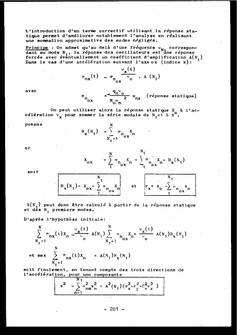
L'introduction d'un terme correctif utilisant la réponse sta-tique permet d'améliorer notablement l'analyse en réalisan tune sommation approximative des modes négligés .
Principe : On admet qu'au delà d'une fréquence v N correspon-dant au mode N 1 , la réponse des oscillateurs est aune répons eforcée avec éventuellement un coefficient d'amplification A(N 1 )Dans le cas d'une accélération suivant l'axe ox (indice x .) :
v x (t )
anx(t)
an
Y o
A ( N1 )o x
q van
_= ., no2unx (réponse statique )
ox
Mnmn
On , peut utiliser alors la réponse statique X àcélération vx pour sommer la série modale de N 1 n1 à No .
avec
1'ac -
N
Rx (N1 ) =
an )( riN1+1 o x
poson s
o r
soit
N
N 1
X
=
ry n Xn = ?c
nXn+ Rx (N 1 )
ri ox
L1 o xox
N1
Rx (N 1 ) .Xox-
ryn Xn
et
rx= xoox
xnox
R(N I ) peut donc être calculé à partir de la réponse statiqu eet des N1 premiers modes .
D'après l'hypothèse initiale :
N
rnx (t)XnN1 +1
Nv (t)
v x
oA(N1)
~noxxn=
x (o t)A(N 1 )Rx (N1 )v
N 1 + 1
N
et max
anx (t)Xn
= A(N 1 )Rx (N 1 )
N 1 + 1
soit finalement, en tenant compte des trois directionsl'accélération,
+ A2(N1)(r23'
,r2 +Cvr 2 )
depour une composant e
N1
rynmx n
n= 1
2x
281 -
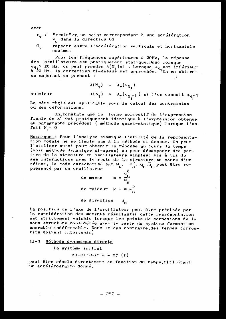
ave c
rx : "reste" en un point correspondant à une accélératio nv0
dans la direction O X
Cv
rapport entre l'accélération verticale et horizontal emaximum
Pour les fréquences supérieures à 20Hz, la répons edes oscillateurs est pratiquement statique .Donc lorsquevN
20 Hz, on peut prendre A(N ) .=1 . Lorsque , est inférieu rà 30 Hz, la correction ci-dessus est approchée . ' On en obtien tun majorant en prenant :
A(N 1 ) =
Ar (v N1 )
ou mieux A(N1 ) AT,( v X +l
) si l'on connait v N + 11 1
La même règle est applicabl eou des déformations .
pour le calcul des contraintes
On constate que le terme correctif de l'expressionfinale de x2 est pratiquement identique à l'expression obtenueau p'ragraphe précédent ( méthode quasi-statique) lorsque l'onfait N1 = O
Remarque_- Pour l'analyse sismique,l'utilité de la représenta-tion modale ne se limite pas à la méthode ci-dessus . On peu tl'utiliser aussi pour obtenir l.a réponse au cours du temp s(voir méthode dynamique ci-après) ou pour décomposer des par-ties de la structure en oscillateurs simples : vis à vis deses interactions avec le reste de la structure au cours d'u nwséisme, le mode caractérisé par Mn,
n
présenté par un oscillateu r
de raideur k = m m2n
de direction
un
La position de l'axe de l'oscillateur peut être précisée pa rla considération des-moments résultants( cette représentatio nest strictement valable lorsque les points de connexions de l . asous structure considérée avec le reste du système forment unensemble indéformable . Dans le cas contraire,des termes correc-tifs doivent intervenir )
II-3 Méthode dynamique direct e
Le système initia l
KX+CX' +MX"
- bi^ (t )
peut être résolu directement en fonction du temps,T'(t) étan tun accélérogramme donné .
2qn
de masse
m =Mn
- 282 -
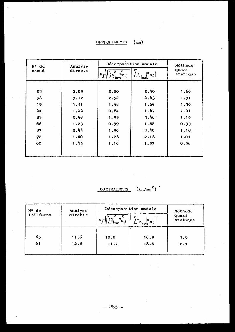
DEPLAC1Th11:NTS (cm )
N° du YseAnalysemodale Méthod e
noeud directe 2
2~,j~1 sa
Xn j Linmais
IXn jIquas istatique
23 2 .09 2 .00 2 .40 1 .66
98 3 .12 2 .52 4 .43 1 .3 1
19 1 .51 1 .48 1 .64 1 .36
44 1 .04 0 .84 1 .47 1 .0 1
83 2 .48 1 .99 3 .46 1 .1 9
66 1 .23 0 .99 1 .68 0 .9 3
87 2 .44 1 .96 3 .40 1 .1 8
72 1 .60 1 .28 2 .18 1 .0 1
60 1 .45 1 .16 1 .97 0 .96
CONTRAINTES (kg/mm2 ))
N° del'élément
Analys edirecte
Décomposition modaleMéthod equas istatique
2
247n
.Lnnnx hj Inn Injn
65
61
11, 6
12 .8
10 . 0
11 .1
16 . 9
18 .6
1 . 9
2 . 1
a) Méthode modal e- ------------ -
Comme au paragraphe précédent, on projette l'équatio ninitiale sur les modes propres, et on se ramène â un systèm ed'équations indépendantespour chaque mode, qui peut être aisé-ment résolu . Les mouvements correspondant à chacun de ces mo -des sont ensuite recombinés pour donner le mouvement en chaqu epoint .
b) Méthode direct e- --------------
Il existe de nombreuses méthodes numériques pour ré-soudre ce type de système ; lorsque la structure est représenté epar un grand nombre de degrés de liberté, le problème de sta-bilité de la méthode de résolution devient prépondérant . De sméthodes telles que Runge et Kutta è rayon de stabilité limit ésont alors inutilisables .
e) Direction de l'accélératio n
Les accélérogrammes verticaux et horizontaux suivan tles deux directions sont en principe différents, et en particu -lier, n' ont pas leur maxima au missile moment .
d) Combinaison des résultats de différents accélérogramme s
Suivant la relation entre
les accélérogrammes uti-lisés et le spectre de référence, il convient. de prendre pou rchaque composante en chaque point, la moyenne ou le maximum de smaximas obtenus pour chaque accé .l érogramme .
p ) Commentaire s
L'avantage principal de l'étude au cours du temps,es tde permettre la prise en compte de phénomènes non linéaires ,tels que la plasticité, la présence de jeux, les chocs ; pa rcontre cette méthode peut devenir coûteuse si le nombre d epoints en temps est trop grand . Tl faut donc choisir un pas qu idonne des résultats corrects sans nécessiter trop de calcul ssur la durée du séisme ( pour un séisme de 10 secondes, si l'o nveut représenter correctement les fréquences jusqu' h 25 liz, i lfaut prendre un pas de 10 -2 secondes ( i+ points par période) c equi conduit à 1000 points de calcul )
IT- te Application
Les trois méthodes : quasi statique,modale avec spectred'oscillateurs, et analyse directe,-ont été appliquées â ] .'en-semble bâtiment principal et structures internes d'une central enucléaire du type à neutrons rapides au sodium (figure 1) .
Les résultats sont portés dans le tableau ci-contre .
- 284 -
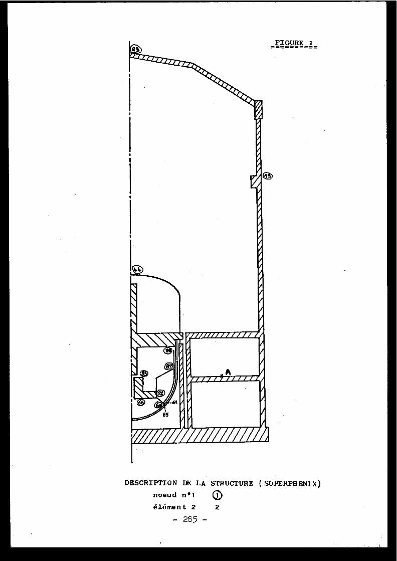
FIGURE 1
woortki/0 /zffmA
DESCRIPTION DE LA STRUCTURE (SUPERPHENIX )
noeud n• 1
élément 2
- 285 -
02
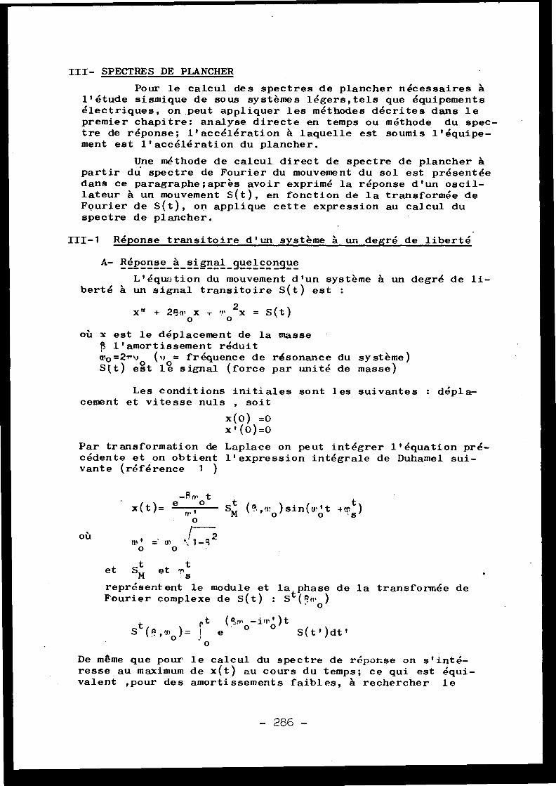
III- SPECTRES DE PLANCHER
Pour le calcul des spectres de plancher nécessaires àl'étude sismique de sous systèmes légers,tels que équipement sélectriques, on peut appliquer les méthodes décrites dans l epremier chapitre : analyse directe en temps ou méthode du spec-tre de réponse ; l'accélération à laquelle est soumis l'équipe -ment est l'accélération du plancher .
Une méthode de calcul direct de spectre de plancher àpartir du spectre de Fourier du mouvement du sol est présentéedans ce paragraphe ;après avoir exprimé la réponse d'un oscil-lateur à un mouvement S(t), en fonction de la transformée deFourier de S(t), on applique cette expression au calcul duspectre de plancher .
III-1 Réponse transitoire d'un système à un degré de libert é
A- Réponse à signal quelconque------------------------ --L'équation du mouvement d'un système à un degré de li -
berté à un signal transitoire S(t) est :
x" + 2pmOx T ,r+
o2x = S(t )
où x est le déplacement de la mass eg l'amortissement rédui tw0 =2nv (v = fréquence de résonance du système )S(t) est le signal (force par unité de masse )
Les conditions initiales sont les suivantes : dépla-cement et vitesse nuls , soi t
x(0) =0x'(0)=0
Par transformation de Laplace on peut intégrer l'équation pré-cédente et on obtient l'expression intégrale de Duhamel sui -vante (référence 1
-Rn+ t
x(t)=e
° St (' ,w )sin(n't +T t )0
n,' _ un ^:/1-3 2
tet SM
et -n t
représentent le module et la phase de la transformée d eFourier complexe de S(t) : St (
?m0
t
rt
(r,+° -irii ) t
S (A,u~o )=
e
S(t')dt 'o
De même que pour le calcul du spectre de réponse on s'inté-resse au maximum de x(t) au cours du temps ; ce qui est équi -valent ,pour des amortissements faibles, à rechercher l e
oûo
o
- 286 -
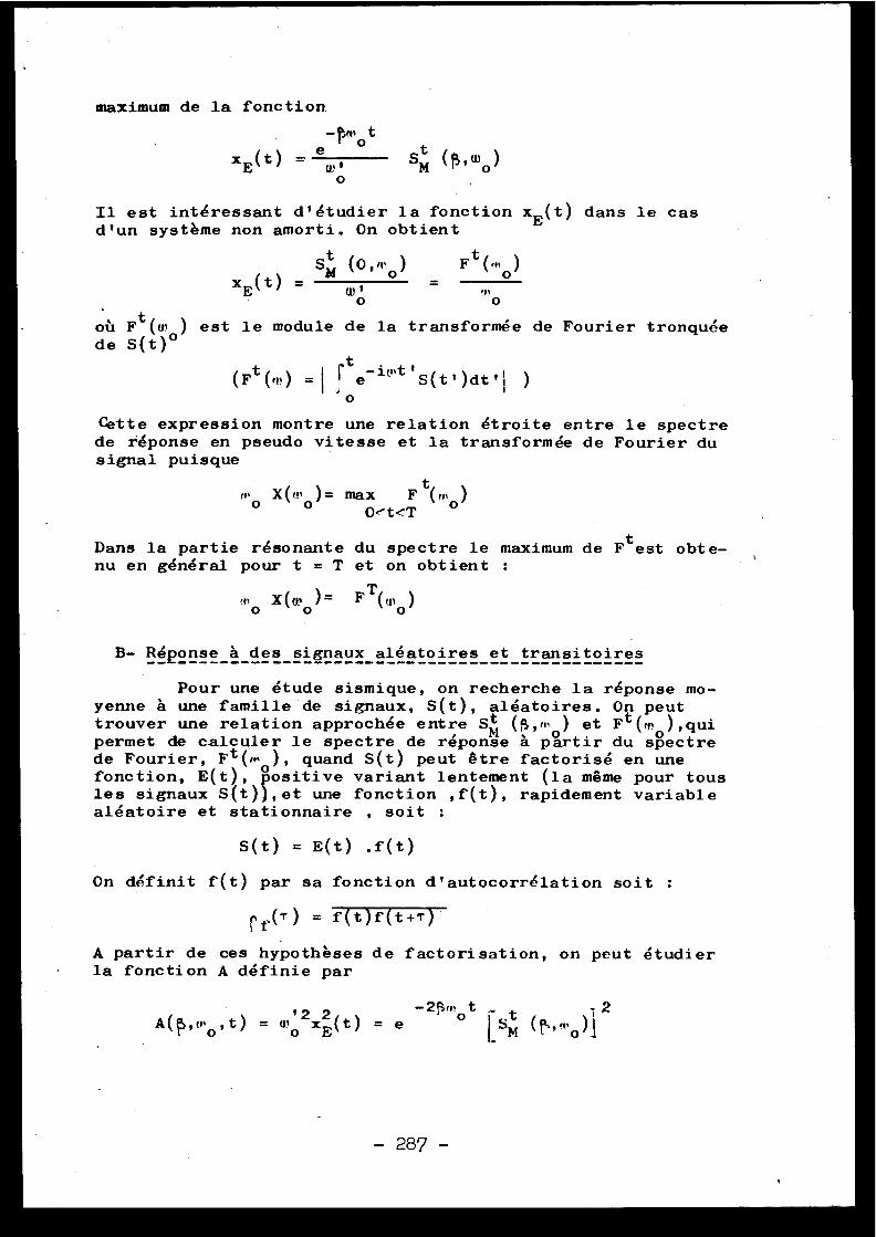
maximum de la fonction
-f5mot
exE (t) = w
0
Il est intéressant d'étudier la fonction xE (t) dans le casd'un système non amorti . On obtien t
Sm
(O,m)
F t (,t,o )xE (t)
w ,o
oû Ft ( ce ,o ) est le module de la transformée de Fourier tronquéede S(t)
r,,o
(Ft (',') =lte in,t' S(t' )dt' j
Otte expression montre une relation étroite entre le spectrede réponse en pseudo vitesse et la transformée de Fourier dusignal puisque
tm o X(w o )= max
F (mo )Oet<T
Dans la partie résonante du spectre le maximum de Ft est obte-nu en général pour t = T et on obtient :
rno
X(w o )= F T(«,o )
B- Réponse à des signaux aléatoires et transitoires----------------------------------------------- -
Pour une étude sismique, on recherche la réponse mo-yenne à une famille de signaux, S(t), aléatoires . On peu ttrouver une relation approchée entre S t (S,ir, ) et Ft (m ),quipermet de calculer le spectre de réponse à partir du spectr ede Fourier, Ft (m ), quand S(t) peut être factorisé en unefonction, E(t), positive variant lentement (la même pour tou sles signaux S(t)),et une fonction ,f(t), rapidement variabl ealéatoire et stationnaire , soit :
S(t) = E(t) .f(t )
On définit f(t) par sa fonction d'autocorrélation soit :
r f () = f(t)f(t+T )
A partir de ces hypothèses de factorisation, on peut étudie rla fonction A définie pa r
A(f) ,mo ,t) = wo2x2 (t) = eE
-2f1mo t
1 2lsM
(f','mo) 1
- 287 -
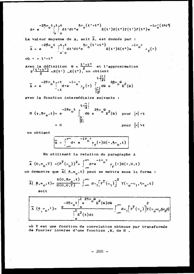
-2qm t l,t t
q
(t'+t")
-iri' ' (t l-t")A= e
° i I dt'dt "e °
E(t')E(t")f(t')f(t ")e
°`o 0
La valeur moyenne de A, soit A, est donnée par :
-2P, t t t
Sm (t ' +t " )
- 1C' T
A = e
°
r dt'dt"e °
E(t')E(t")e
°
f(T )
o o
où T = t'-t "
Avec la dfinition Q = t'+t" et l'approximatio n
E (tt+tu1 _.E(t') ,,,E(t"),2on obtien tT `
-2£m t +t
-im T
t~21 20w 9A = e
°
dTe
° pf (T)
dA e
° E2 (9 )
avec la fonction intermédiaire suivante :
1T I
-2Awot t 2, 2qwg
H (T,Rmo ,t)= e
` dQ e
E2 (g) pour 1T' et
= O
pour (Tl > t
on obtient
_
r+m
-1R! T
A = I d er e
° f(T)H(T,qm°,t )
-mn
En utilisant la relation du paragraphe A
_
in+
-i n n T
A (O, mo ,T ) =(FT(m°))2= ` dTe
° 0 (T)H(T,O,t ); Iron demontre que A( (i,n• o ,t) peut se mettre sous la forme :
H(0,5mo ,t) s'Y'A( . fÿ,mo,t)= H(O,O,T)
dv1'-
(v1 )]2 Y(v ° -v 1 ,Qjrr ° , t )
soit
où Y est une fonction de convolution obtenue par transformé ede Fourier inverse d'une fonction ,W, de H
t 2Am Q-2(~m° tf e
° E2 (8)dQ
2
rT 2
~ dv 11 FT(v1 )]Y ( vo1 ,5,"dt)I', E (t)d t
o
A
1
- 288 -
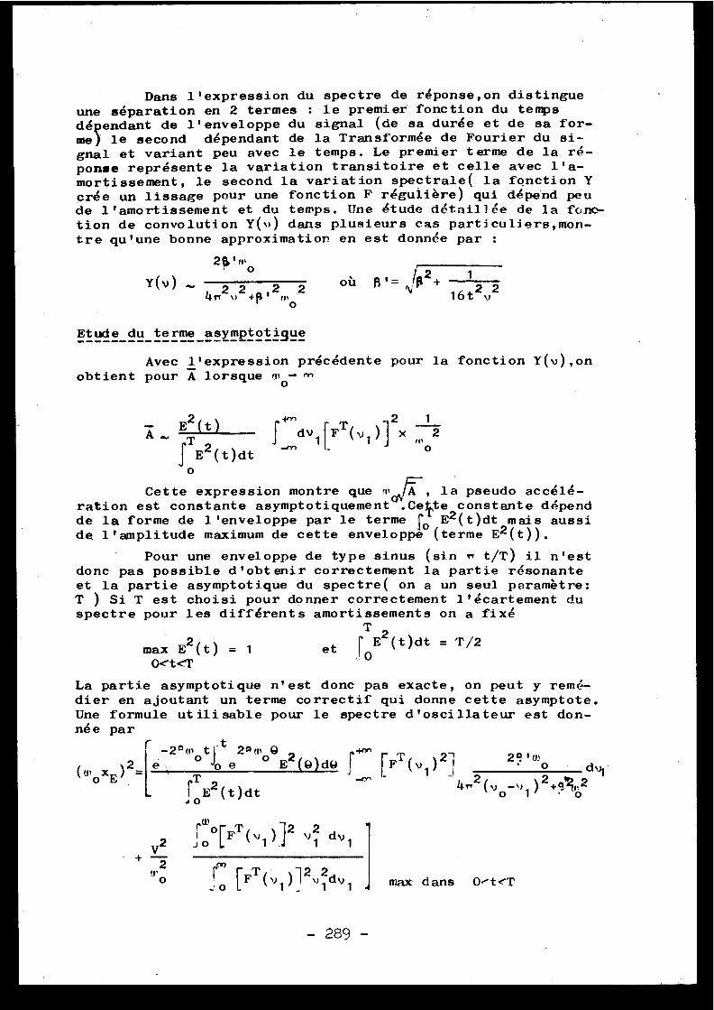
Dans l'expression du spectre de réponse,on distingueune séparation en 2 termes : le premier fonction du temp sdépendant de l'enveloppe du signal (de sa durée et de sa for-me) le second dépendant de la Transformée de Fourier du si-gnal et variant peu avec le temps . Le premier terme de la ré-ponse représente la variation transitoire et celle avec l'a-mortissement, le second la variation spectrale( la fonction Ycrée un lissage pour une fonction F régulière) qui dépend pe ude l'amortissement et du temps . Une étude détaillée de la fonc -tion de convolution Y(O dans plusieurs cas particuliers,mon-tre qu'une bonne approximation en est donnée par :
2$'m 0
Etude du terme asymptotiTl!Avec l'expression précédente pour la fonction Y(v),on
obtient pour A lorsque0
fE2 (t)dt0
Cette expression montre que la pseudo accélé-ration est constante asymptotiquement .Celte constante dépen dde la forme de l'enveloppe par le terme f E2 (t)dt mais ausside l'amplitude maximum de cette enveloppe (terme E 2 (t)) .
Pour une enveloppe de type sinus (sin n t/T) il n'estdonc pas possible d'obtenir correctement la partie résonant eet la partie asymptotique du spectre( on a un seul paramètre :T ) Si T est choisi pour donner correctement l'écartement duspectre pour les différents amortissements on a fix é
T
max E2 (t) = 1
et f E2 (t)dt = T/2
O.et<i'
, . 0
La partie asymptotique n'est donc pas exacte, on peut y remé-dier en ajoutant un terme correctif qui donne cette asymptote .Une formule utilisable pour le spectre d'oscillateur est don-né e par
-2°motJ 4:t 2Qwoe 2
I é'
oe
E (Q)dO f
-
Y(v)
où B'_ ,.. ..
1
4 v2 v 2 +~1' 2 mo2
16t 2, 2
A
E2 (t)
_
2
1
T
j dv1 [F
1 )] x f" 2-en
o
(u,oxE ) 2 =
+ 2
uo
ro[FT ( 1 )i 2 \,dU 1
~oTE2 (t)dt
y2
~0 [FT(v1)J21
dv 1
T
21
2R' mF (v 1 ) o (h --, 2
) 2 + s'R,, 20 1
0
max dans OiteT
- 289 -
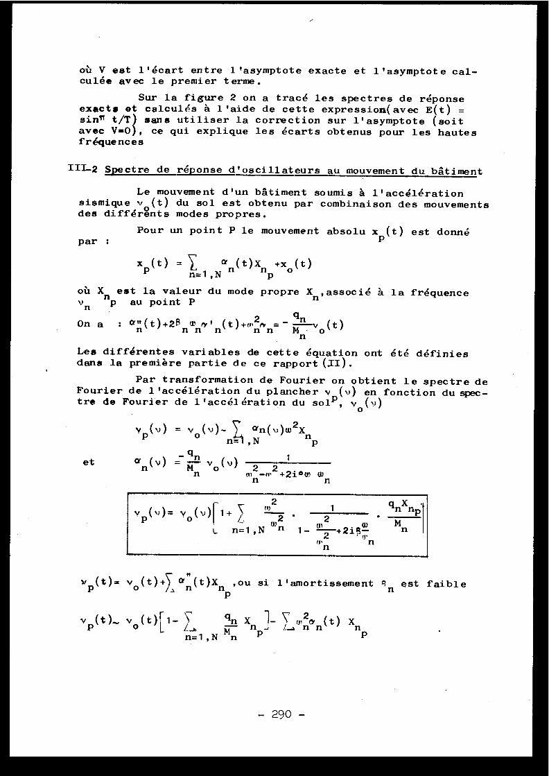
où V est l'écart entre l'asymptote exacte et l'asymptote cal-culée avec le premier terme .
Sur la figure 2 on a tracé les spectres de réponseexacts et calculés à l'aide de cette expression(avec E(t) =sin" t/T) sans utiliser la correction sur l'asymptote (soi tavec V=0 , ce qui explique les écarts obtenus pour les haute sfréquence s
In-2 Spectre de réponse d'oscillateurs au mouvement du bâtimen t
Le mouvement d'un bâtiment soumis à l'accélératio nsismique v (t) du sol est obtenu par combinaison des mouvement sdes différgnts modes propres .
Pour un point P le mouvement absolu xp (t) est donnépar :
xp (t) =
a (t)X +x(t )n=1,N n
np o
où X est la valeur du mode propre X ,associé à la fréquenc ev np au point P
nn
On a : au (t)+20 T
(t) +m2n =- qnv (t )n
n n n
n n Mn. o
Les différentes variables de cette équation ont été définie sdans la première partie de ce rapport W) .
Par transformation de Fourier on obtient le spectre d eFourier de l'accélération du plancher v (v) en fonction du spec-tre de Fourier de l'accélération du so1P, v o ( v )
Y (v) = v (v)- C an(v)w 2XP
°
n1 , N
nP
an (v)
Mn vo (v) 2 2 1n
m• -m +2i 0 w w
n
n
v
t"2 1 gnXnP= Y o ( ) r 1+ i,
w2
2n=1,N n 1-
+2igw
Mn
2
mnn
v p (t)= vo lt)+yS an( t )Xn ,ou si l'amortissement R n est faibl eP
v ..( t ) .. v (t) 1-LI.
qn Xn 1-
mnxn (t) Xn
n=1,N Mn P
p
et
- 290 -
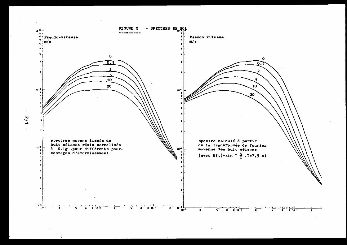
spectres moyens lissés dehuit séismes réels normalisé sà 0 .lg ,pour différents pour-centages d'amortissement
spectre calculé à parti rde la Transformée de Fouriermoyenne des huit séisme s
(avec E(t)=sin n T ,T=7,5 s)
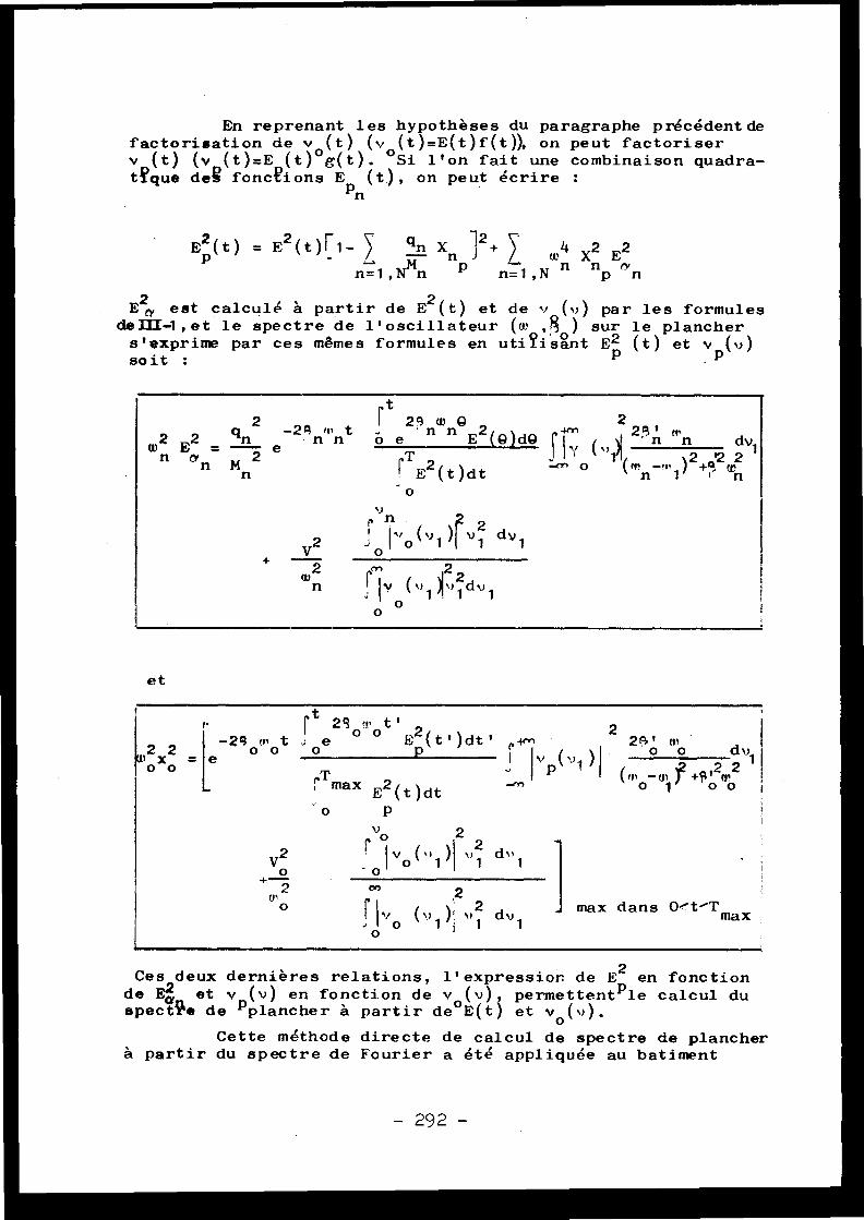
En reprenant les hypothèses du paragraphe précédent defactorisation de v (t) (v (t)=E(t)f(t)), on peut factorise r
(t) (v (t)=E (t)°g(t) . °Si l'on fait une combinaison quadra-t?que degs fonctions Ep (t), on peut écrire :
n
E2 (t) = E2(t)r1- Xn 12+ / ~~4 X2 E2
n 1,N n
n=1,N n np rn
E0, est calculé à partir de E2 (t) et de v (v) par les formule sdeIII1 , et le spectre de l'oscillateur (a, , f ) sur le planchers'exprime par ces mêmes formules en uti?isant E2 (t) et v p (v )soit :
et
Ste20fP0ttE2(tt)dtt
2
Itt 2 2
-29 omo t
m 1oxo
e p ( Iv v1 0 0
22"1
maxE2(t)dt
o
-o o
o
P
t
+V2
w2n
2 wn
2eE 2 (A)dAP n
23' noisdvl~!
n
21
-en o 1 (mn1)Z+atZwn
' ov
zro 1 „o (~~ 1 )I v 1 dy 1
! 1 v ( ~> 1 k, dv 1,
00
w2 E2 =
qn2
e-Zannto
n an m 2
T 2
n
r
(t)dt
2
2
(v1i
)l 21
dv 1 max dans O%t-T
V2o2
mo
2
max
)
Ces deux dernières relations, l'expressior de E 2 en fonctio nde E2 et v (v) en fonction de v (v), permettent ple calcul duspectre de plancher à partir de°E(t) et v o (v) .
Cette méthode directe de calcul de spectre de planche rà partir du spectre de Fourier a été appliquée au batimen t
- 292 -
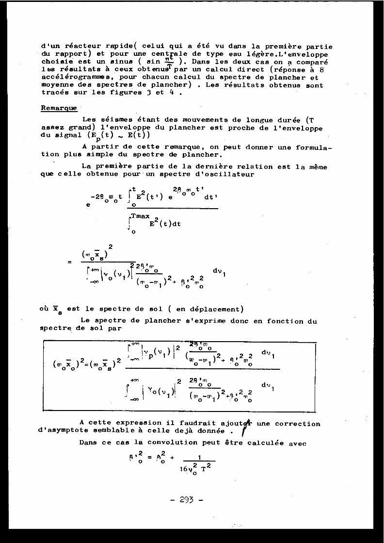
d'un réacteur rapide( celui qui a été vu dans la première parti edu rapport) et pour une centrale de type eau légére .L'enveloppechoisie est un sinus ( sin 74- ) . Dans les deux cas on a compar éles résultats à ceux obt enusT par un calcul direct (réponse à 8accélérogrammes, pour chacun calcul du spectre de plancher e tmoyenne des spectres de plancher) . Les résultats obtenus sonttracés sur les figures 3 et 4 .
Remarque
Les séismes étant des mouvements de longue durée (Tassez grand) l'enveloppe du plancher est proche de l'envelopp edu signal (Ep (t)
E(t) )
A partir de cette remarque, on peut donner une formula -tion plus simple du spectre de plancher .
La première partie de la dernière relation est la mêm eque celle obtenue pour un spectre d'oscillateu r
rt
2g m t '-2 } owot j E2 (t') e ° ° dt '
e
o
,Tmax1
E2 (t)dt
2
Jo
1dv
où 78 est le spectre de sol ( en déplacement )
Le spectre de plancher s'exprime donc en fonction d uspectre de sol pa r
A cette expression il faudrait ajout une correctiond'asymptote semblable à celle dejà donnée .
Dans ce cas la convolution peut être calculée ave c
R
2
2+ 1
~o - ~o1692 T 2
( . x ) 2_(m x0 0
o s
r
I .2
23'wo{yp(v1
(0)0_0,1 ) 2 + o2ô d ~~ 1
28' m~2 0o dv 1
Y0(v1
(mo -n+ 1 )2+9ô 2,"
2
-293-
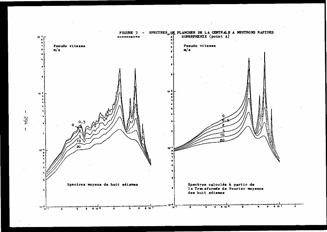
FIGURE 3====mam==a
SPECTRESm .AE PLANCHER DE LA CENTRALE A NEUTRONS RAPIDESa
SUPERPHENIX (point A )tI .c,
Pseudo vitesse
s•
m/s
Spectres calculés à partir dela Transformée de Fourier moyennedes huit séismes
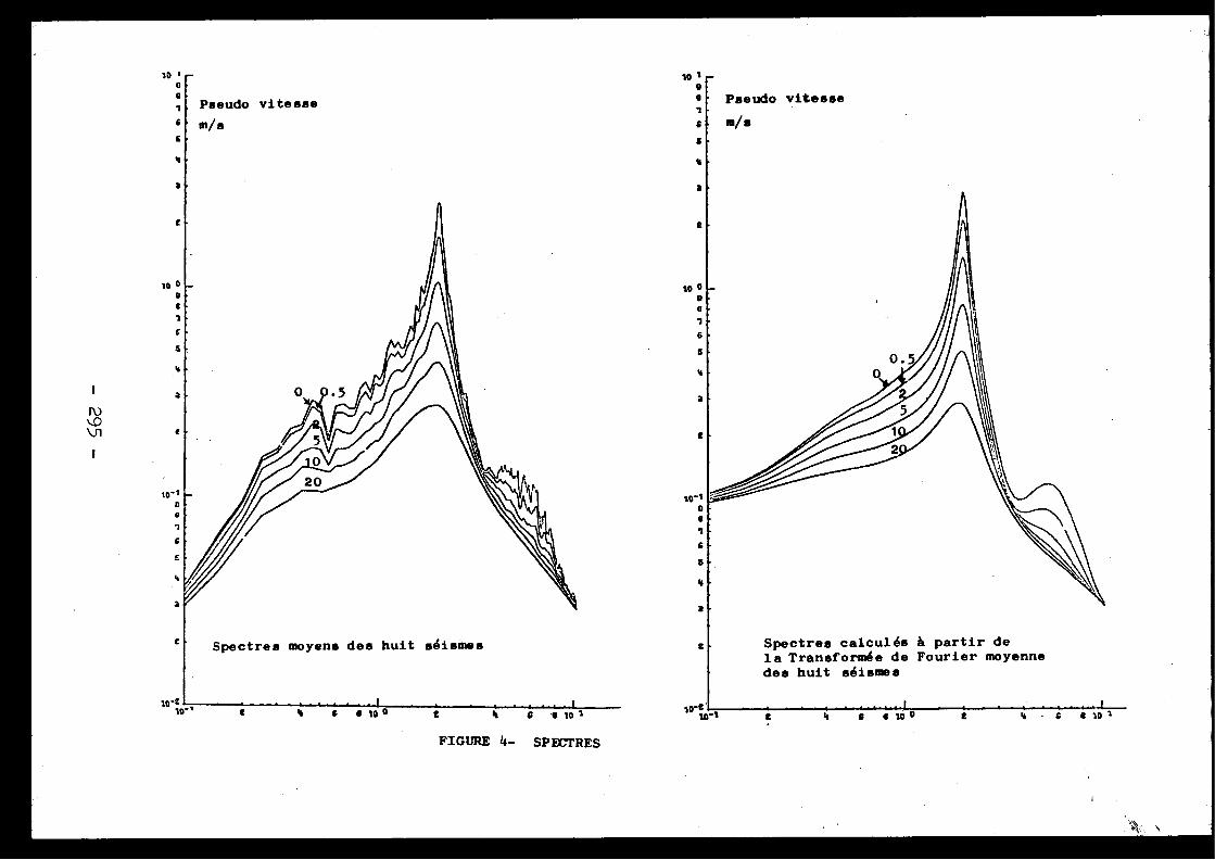
FIGURE 4- SPECTRES
Spectres calculés â partir d ela Transformée de Fourier moyennedes huit séismes
Pour tous les amortissements non nuls cette hypothèse est jus-tifiée . Une autre approximation consiste à re lecer le déno-minateur de l'expression précédente par v o (vfl . En effet,s ila convolution est importante pour les spectres de plancher ,elle l'est beaucoup moins pour les spectres d'oscillateurs .On a ainsi défini une formulation simplifiée du spectre deplancher .
IV- CONCLUSIO N
La comparaison entre les différentes méthodes de cal -cul de
réponse aux séismes montre que pour des systèmes com-plexes ,la méthode quasi statique ne peut donner de bons résul -tats . Par contre, la méthode modale fournit des résultats cor-rects par comparaison avec la méthode directe .
Cette méthode modale, compte tenu de son coût plu smodéré et de sa plus grande facilité d'utilisation est doncà employer dans la plupart des cas .
La méthode de calcul des spectres de plancher présen-tée dans ce rapport en est un complément naturel, et perme td'éviter toute référence à des accélérogrammes .
REFERENCES
F .JEANPIERRE et M .LIVOLANT"Direct calculation of the floor response spectr a"from the Fourier transform of the ground movement -"Application to the Super Phénix fast reactor Project "Séminaire ELCALAP -Berlin ,Septembre 1975 - U 1/6
J .M .BIGGS"Seismic response spectra for equipment design i n"nuclear power plant "ler SMIRT, Berlin ,Septembre 1971 - K 4/ 7
R .H .SCANLAN and K .SACHS"Floor response spectra for multi degree of freedo m"systems by Fourier Transform "3ème SMIRT, Londres,Septembre 1975 ,K 5/ 5
L .LAZZERI"Floor response spectra by the use of a modified whit e"noise technique "2ème SMIRT, Septembre 1973 -K 4/2
C .CHEN"Comments on floor response spectra "2ème SMIRT, Septembre 1973 - K 4/ 3
r i -1
r
r31
r 4 ,
r 5 i
- 296 -

Discussions
J .L.ZEMAN, Austri a
One remark on the superposition problem : We, too ,did compare results obtained by the SRSS (Square Root of theSum of the Squares) method with those obtained by what yo ucalled direct integration methods . We too found the firs tresults in many cases up to 25 % on the nonconservative side ,inothersup to 40 % on the conservative one . We found that theNRL-method (which uses the absolute value of the maximum con-tribution plus the SRSS of the remaining ones) to be in mos tcases conservative and if not conservative, then only to anegligible percentage .
In my opinion, we should abandon the SRSS metho dcompletely . Having doubts in the figures the geologists giv eus does not justify using deliberately nonconservative method son our side, at least not in a deterministic approach .
J .V . PARKER, United Kingdom
What methods have been used for direct integratio nof the equations of motion ?
M. LIVOLANT, Franc e
Une méthode inconditionnellement stable pour l arésolution directe du système initial . Dans le cas où uneprojection sur une base modale est traitée au préalable, un eméthode analytique par intervalles est utilisée, lorsqu'i ln'y a pas de couplage par amortissement .
D . COSTES, Franc e
Quelle est la différence de temps de calcul entr ele calcul historique direct et le calcul historique avec dé -composition modale ?
M. LIVOLANT, Franc e
Pour le calcul présenté, comportant environ 40 0degrés de liberté, le calcul avec décomposition modale demandeun temps inférieur au dixième de celui de l'autre méthode .
F.HENNING, Belgique
Etant donné le manque de conservatisme constaté dansles valeurs d'accélération à certains niveaux du modèle présent é
- 297 -

par M. Livolant, lorsqu'on effectue une analyse modale ave ccombinaison des réponses modales en SRSS (par rapport auxméthodes directes), l'auteur a-t-il essayé de regrouper le sréponses de modes de fréquences proches avant de sommer le scarrés ?
Que pensent les experts européens de la positionde l'USAEC à ce sujet (cfr . Regulatory Guide 1 .52) ?
M. LIVOLANT, France
Il n'y a pas eu de tentative de regrouper les ré -ponses de modes de fréquences proches, car l'écart relati fentre les fréquences prises en compte est supérieur à 20 % .
[4 .4]
AN ANALYSIS ON THE DYNAMIC BEHAVIO ROF BOILING WATER REACTOR CORE
Youichi Sasaki, Yukio Sasaki and Takuro Hayash iTokyo Shibaura Electric Co ., Ltd .
Tokyo, Japan
Paper presented by H . Shibata
In order to establish a method of anti-seismic design ofBWR core, we have prepared an experimental model to simulat ethe dynamic behavior of BWR core and carried out vibrationtesting. We have developed a theory in order to analyze thefuel motion on the assumption that the core is multi-degre eof freedom system which consists of the elastic beams sur -rounded by water .
From these investigations, we concluded that a singl edegree of freedom system is applicable to core for anti -seismic design of it .
Avec le but d'établir la méthode du dessin anti -sismiqu epour le réacteur d'eau bouillante avec . noyau BWR nous avon spréparé un modèle expérimental pour activer le fonctionne -ment dynamique du noyau BWR et nous avons réalisé des essai sde vibration . Nous avons aussi developpé une théorie laquell epermet d'analyser le mouvement du combustible, en supposan tque le noyau est du type â degrés multiples, système indé-pendant, lequel se compose de faisceaux élastiques entouré sd'eau, D'après cette recherche on a conclu qu'un seul degrédu système indépendant peut être employé dans le noyau pou rson dessin anti, sismique .
1.
IntroductionThe anti-seismic design of core fuel assemblies is on e
of the most important parts of the BWR nuclear power plan tdesign . The range of natural frequencies of the fuel assem-blies is similar to that of the natural frequency of the re -actor building and the predominant frequency of the earth -quake . The damage of the fuel assembly may lead the radio -active accident, so we must investigate the anti-seismi canalysis of the reactor core seriously .
Because the core consists of many fuel assemblies and i sin water, it is very difficult to investigate the dynamic be-havior of the reactor core . This difficulty mainly depend supon the fact that the reactor core is not only considered a sthemultidegrees of freedom system, but the interaction be-tween the water and the fuel assemblies must also be take ninto consideration . We have prepared 21 fuel assembly model son the scale of about a quarter, and set them in a rectangu-lar lattice shape in the tank, and carried out the vibratio ntests using the high power vibration testing machine . Thetheoretical results coincide with the experimental results .We are convinced that the dynamic characteristics of fue lassemblies in the core can be calculated by the approximat etheory and that the assumption that the fuel assemblies i nthe core move in the same phase is reasonable .
2.
Experiment2-1 Experimental apparatu sWe have planned a core model for testing in which th e
number of fuel assembly models can be changed and which w ecan vibrate using our testing machine . The natural frequenc yof the fuel models decreases according to the increment o fthe virtual mass, and the external force in water is influ-enced by the virtual mass and the displaced mass of water .The fundamental test plan is as follows ,(i) To increase the number of the fuel assembly models a s
far as possible .(ii) To increase the virtual mass in order to clear the dif-
ference between the natural frequency in air and tha tin water . For this purpose, the gaps between the tan kwall and the core are decreased as possible .
(iii)To increase the difference between the density of fue land that of water in order to increase the externa lforce .
(iv) To keep the natural frequency of the tank considerabl yhigher than that of the fuel assembly models .Based on this fundamental plan, we have decided tha t
the scale of the fuel assembly model is about 1/4, and se tthem in a rectangular lattice shape in the tank . The cros ssection of the tank and the details of this model fuel as-sembly are shown in Figs . 1 and 2 .
The fuel assembly models supported flexibly on th eplenum plates at the both ends . And their natural frequ-encies are adjustable in some range .
To treat the reactor core as two dimensional theoreti-cal model, we planned to prepare the wide spaces above an d
- 300 -
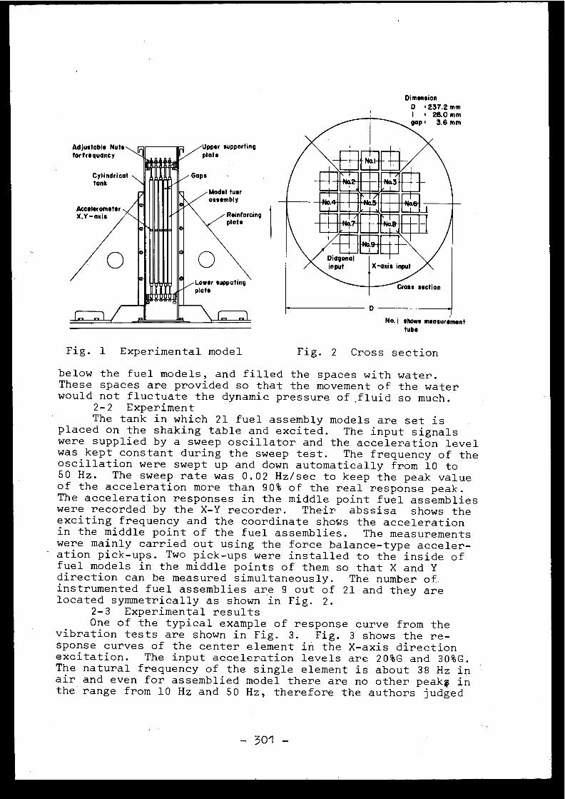
Adjustable Nuts
Upper supportin gplat sfort requancy
1111
M. .Ti IPPI'PPll l
Fig . 1 Experimental model
Fig . 2 Cross section
below the fuel models, and filled the spaces with water .These spaces are provided so that the movement of the wate rwould not fluctuate the dynamic pressure of . fluid so much .
2-2 ExperimentThe tank in which 21 fuel assembly models are set is
placed on the shaking table and excited . The input signal swere supplied by a sweep oscillator and the acceleration leve lwas kept constant during the sweep test . The frequency of th eoscillation were swept up and down automatically from 10 to50 Hz . The sweep rate was 0 .02 Hz/sec to keep the peak valueof the acceleration more than 90% of the real response peak .The acceleration responses in the middle point fuel assemblie swere recorded by the X-Y recorder . Their abssisa shows th eexciting frequency and the coordinate shows the acceleratio nin the middle point of the fuel assemblies . The measurement swere mainly carried out using the force balance-type acceler-ation pick-ups . Two pick-ups were installed to the inside o ffuel models in the middle points of them so that X and Ydirection can be measured simultaneously . Thé number o finstrumented fuel assemblies are 9 out of 21 and they arelocated symmetrically as shown in Fig . 2 .
2-3 Experimental result sOne of the typical example of response curve from th e
vibration tests are shown in Fig . 3 . Fig. 3 shows the re-sponse curves of the center element in the X-axis directio nexcitation . The input acceleration levels are 20%G and 30%G .The natural frequency of the single element is about 38 Hz i nair and even for assemblied model there are no other peak ; i nthe range from 10 Hz and 50 Hz, therefore the authors judge d
- 301 -
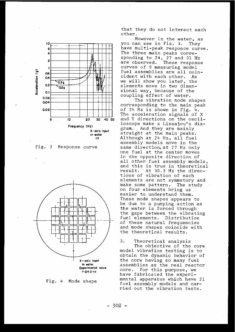
10
64
2
0.06
0.04
0.02
io
that they do not interact eachother .
However in the water, a syou can see in Fis . 3 . Theyhave multi-peak responce curve .The three main peaks corre-sponding to 24, 27 and 31 H zare observed . These respons ecurves of 9 measuring modelfuel assemblies are all coin -cident with each other . Aswe will show you later', th eelements move in two dimen-sional way, because of th ecoupling effect of water .
The vibration mode shape scorresponding to the main pea kof 24 Hz is shown in Fig . 4 .The acceleration signals of X
20 30 40 50 and Y directions on the oscil -loscope make a Lissajou's dia-gram. And they are mainl y
wate rix
inpu tin
straight at the main peaks .Although at 24 Hz, all fue lassembly models move in thesame direction, at 27 Hz onl yone fuel at the center move sin the opposite direction ofall other fuel assembly models ,and this is true in theoretica lresult . At 30 .3 Hz the direc-tions of vibration of eachelements are not symmetory andmake some pattern . The studyon four elements bring u seasier to understand them .These mode shapes appears tobe due to a pumping action a sthe water is forced throughthe gaps between the vibratin gfuel elements . Distributionof these natural frequenciesand mode shapes coincide withthe theoretical results .
(Hz )
X-axis
3 .
Theoretical analysi sThe objective of the cor e
model vibration testing is t oobtain the dynamic behavior o fthe core having so many fuelassemblies as the real reactorcore . For this purpose, wehave fabricated the experi-mental apparatus which have 2 1fuel assembly models and car-ried out the vibration tests .
i
'\ 0.3q----_
l
J~ )
-0.2q r
Frequenc y
Fig . 3 Response curve
Fig . 4 Mode shape
- 302 -
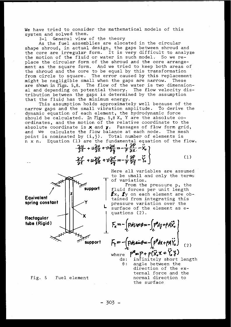
We have tried to consider the mathematical models of thi ssystem and solved them .
3-1 General view of the theoryAs the fuel assemblies are alocated in the circula r
shape shroud, in actual design, the gaps between shroud an dthe core are irregular form . It is very difficult to analyz ethe motion of the fluid or water in such model . So we re -place the circular form of the shroud and the core arrange -ment as the square form . And we tried to keep both areas o fthe shroud and the core to be equal by this transformationfrom circle to square . The error caused by this replacemen tmight be negligible small when the gaps are narrow . Thes eare shown in Figs . 5,8 . The flow of the water is two dimension -al and depending on potential theory . The flow velocity dis-tribution between the gaps is determined by the assumptionthat the fluid has the minimum energy .
This assumption holds approximately well because of th enarrow gaps and the small vibration amplitude . To derive th edynamic equation of each element, the hydrodynamic forc eshould be calculated . In Figs . 5,8 X, Y are the absolute co -ordinates, and the motion of the relative coordinate to th eabsolute coordinate is x and y . Passages of flow form grid ,and we calculate the flow balance at each node . The mes hpoint is nominated by (i,j) . Total number of elements i sn x n . Equation (1) are the fundamental equation of the flow .
+u.i tl -a
P ax ^~
tuli +v -_Q â
(1 )
Here all variables are assume d to be small and only the terms
of variation .From the pressure p, the
Support
fluid forces per unit lengt h(x,fy on each element are ob -Equivalent
tained from integrating thi sspring constant
L pressure variation over th esurface of the element as e -quations (2) .
Rectagular tube (Rigid) Fx~-fPd5~8~-f~d~+pAxo
-
G
C
6,=- prisa -fr%ttAYo (2 )
where po'p+ P(Xo' + ods : infinitely short lengt h6 : angle between th e
direction of the ex-ternal force and the
Fig . 5
Fuel element
normal direction t othe surfac e
-303-
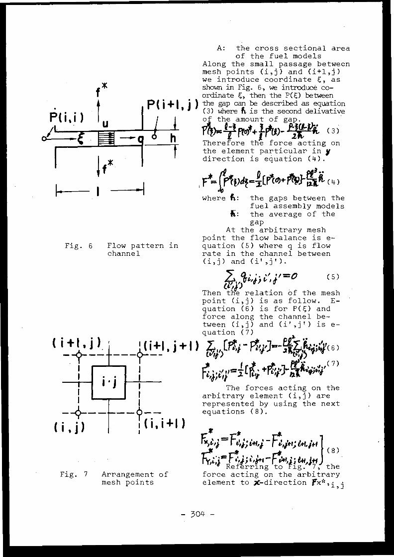
1
+I )
Fig . 6
Flow pattern inchanne l
Fig. 7 Arrangement o fmesh points
A: the cross sectional areaof the fuel model s
Along the small passage betwee nmesh points (i,j) and (i+l,j )we introduce coordinate , asshown in Fig . 6, we introduce co -ordinate , then the P() between
) the gap can be described as equation(3) where fi . is the second delivativeof the amount of gap .
p ;~ prod+Jew- ~r~%. (3 )
Therefore the force acting onthe element particular in ydirection is equation (4) .
I il)4=.Z(i%+ r,fl- (4 )
where fi, : the gaps between th efuel assembly model s
K : the average of th egap
At the arbitrary meshpoint the flow balance is e-quation (5) where q is flo wrate in the channel betwee n(i,j) and (i',j') .
Z c ,j; 4;'4'0
Then the relation of the mes hpoint (i,j) is as follow . E -quation (6) is for P() andforce along the channel be-tween (i,j) and (i',j') is e -quation (7)
Dot - -
toef)
'r
Citi)
f
(7 )
,a,t, ►t
I.
The forces acting on thearbitrary element (i,j) arerepresented by using the nextequations (8) .
Ç*
*ee .=F . .
-Ft ,641 144
t,p).ti;ttf,Al
sr
["
1
(8 )
Referring to ig . 7, theforce acting on the arbitraryelement to X-direction ~i, j
(5 )
-304 -
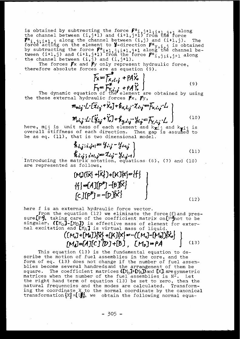
is obtained by subtracting the force Pi
+ alongthe channel between (i,j+l) and (i+l,j+13 from ta forc eFr*i,j ;i+1 - along the channel between (i,j) and (i+l,j) . Theforce act i
13ng on the element to u-direction Py,i~ is obtaine d
by subtracting the force f*i+l,j ;i+l,]+l along the channel be-tween (i+l,j) and (i+l,j+l) from the force
alongthe channel between (i,j) and (i,j+l) .
The forces fx and fy only represent hydraulic force ,therefore absolute forces are as equation (9) .
Fx Te,j. + PA$ 'Fir
*
+PAY
(9 )
The dynamic equation of the element are obtained by usin gthe these external hydraulic forces fx, fry ,
, .G. [ , .+ I•] .4
- N , .^r
,
(10 )
here, mij is unit mass of each element and kxij and kvil i soverall stiffness of each direction . Then gap is assuied t obe as eq . (11), that is two dimensional model .
.y~
t~ (11 )1001'444
''J
d~',~Introducing the matrix notation, equations (6) ,are represented as follows,
(7)
and (10)
here f is an external hydraulic force vector .From the equation (12) we eliminate the force{f}and pres-
sureCP'9, taking care of the coefficient matrix on(lnot to besingular ; ((Mo]-LMD]) is effective mass of element for exter-nal excitation and [MAI is virtual mass of liquid .
(1M.] +C► 1A 1iJ<34xJ =-CC H.j-CM;7)I3 JLM11=(41(CJ C7J+CB) , 010= PA
(13 )
This equation (13) is the fundamental equation to de -scribe the motion of fuel assemblies in the core, and theform of eq . (13) does not change if the number of fuel assem-blies become several handredsand the arrangement of them besquare . The coefficient matrices (t M03+EMA])and tKJ_aresymmetri cmatrices when the number of the fuel assemblies is N 2 . Letthe right hand term of equation (13) be set to zero, then th enatural frequencies and the modes are calculated . Transform-ing the coordinate X,,to the normal coordinate by the canonica ltransformation{X}=(i, we obtain the following normal equa -
_
C 4.)() .1x4)+CK74}=1f -Jff I ng(Ai) -Le*1[c3u93=-fr;1*1
(12 )
-305 -
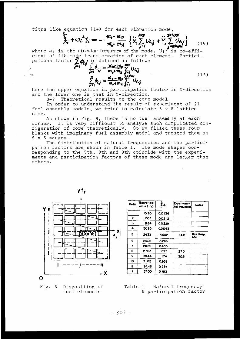
tions like equation (14) for each vibration mode ,
2 Itt p
ffi,,f txoZ4 0'4 't Ye 7- 01'4}
( 14 )
where wi is the circular frequency of the mode, Ui jiis o-effi -
cient of ith mo e transformation of each element . Partici-pations factor
01t,os
is defined as follows
w
Olt `►4
?Pt,+ m,,
`►k4t
aAtla/~~ - f/t e .}n6A t i
-
here the upper equation is participation factor in X-directio nand the lower one is that in Y-direction .
3-2 Theoretical results on the core mode lIn order to understand the result of experiment of 2 1
fuel assembly models, we tried to calculate 5 x 5 lattic ecase .
As shown in Fig . 8, there is no fuel assembly at eac hcorner . It is very difficult to analyze such complicated con -figuration of core theoretically . So we filled these fou rblanks with imaginary fuel assembly model and treated them a s5 x 5 square .
The distribution of natural frequencies and the partici-pation factors are shown in Table 1 . The mode shapes cor -responding to the 5th, 8th and 9th coincide with the experi-ments and participation factors of these mode are larger tha nothers .
j: f
yfr
(15 )
r_,
F r--i
L_J E -~:u. j
• XoŸô)
c
r ,L_ JH+-- j n
X
Order 7heoretico lvalue (Hz) 1•i 'Il
Ezperi men -toi vaiue(Hz) Note s
1 15 .90 0.01362 17.03 0.021 23 18 .64 0.02294 20.95 0.0043
5 24.33 r
4.602 24 .0 ArOX.Resp .
6 25 .06 0.26 3
7 2626
j 0.43 3
8 27.03 1 .095 27. 09 30.44 1 . 174 30 :3
10 31 .02 0.953
_
1
I 34.43 Q 236_12 37.00
_ _0.153
X Ifx
0
Fig . 8 Disposition o ffuel elements
Table 1
Natural frequenc ya participation factor
- 306 -
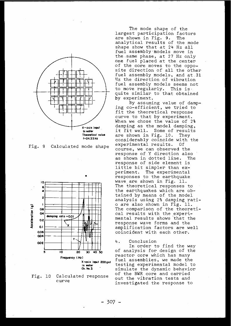
Fig . 9 Calculated mode shap e
e
damping ratio . 0.0I
r
5
I0
20 30 40 50
Frequency (Hz )X-axis input 200ga Iin wate rCh . No. 3
Fig . 10 Calculated respons ecurve
The mode shape of th elargest participation factorsare shown in Fig . 9 . Th eanalytical results of the modeshape show that at 24 Hz al lfuel assembly- models move inthe same phase, at 27 Hz onl yone fuel placed at the cente rof the core moves to the oppo-site direction of all the othe rfuel assembly models, and at 3 1Hz the direction of vibrationfuel assembly models seems notto move regularly . This is .quite similar to that obtainedby experiment .
By assuming value of damp-ing co-efficient, we tried t ofit the theoretical respons ecurve to that by experiment .When we chose the value of 2 %damping as the model damping ,it fit well . Some of result sare shown in Fig . 10 . Theyconsiderably coincide with th eexperimental results . O fcourse, we can observed theresponse of Y direction als oas shown in dotted line . Th eresponse of side element i slittle bit simpler than ex-periment . The experimenta lresponses to the earthquak ewave are shown in Fig . 11 .The theoretical responses t othe earthquakes which are ob-tained by means of the mode lanalysis using 2% damping rati -o are also shown in Fig . 11 .The comparison of the theoreti -cal results with the experi-mental results shows that th eresponse wave forms and th eamplification factors are wel lcoincident with each other .
4 .
ConclusionIn order to find the way
of analysis for design of thereactor core which has man yfuel assemblies, we made th etesting experimental model t osimulate the dynamic behavio rof the BWR core and carrie dout the vibration tests an dinvestigated the response t o
I0
64
2
0.6Q4
0 .2
0. 1
Q06Q04
Q02
-307 -
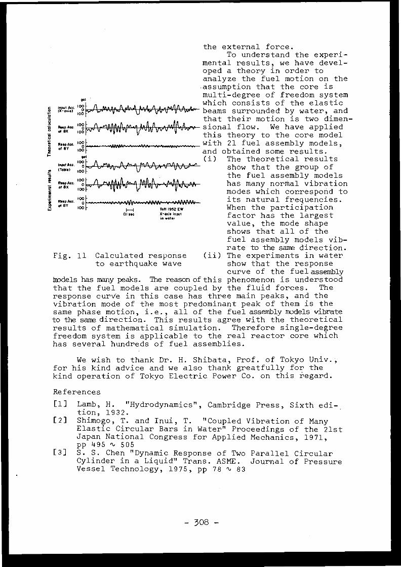
the external force .To understand the experi-
mental results, we have devel-oped a theory in order t oanalyze the fuel motion on th eassumption that the core i smulti-degree of freedom syste m
1n ut Ac4 10 which consists of the elasti c° 'rO"`' loô
beams surrounded by water, an dthat their motion is two dimen -
b %s°Aee 100-
,, „I
.,II ► .~ .
sional flow .
We have applie dof ax ,o$
t 1
t r~ ►
this theory to the core mode lR ° wAcc i oo
-
.,
with 21 fuel assembly models ,r of 8Y 100-
and obtained some results .(i) The theoretical result s
irAcc
1000 ~/~ ~, `ti ~.100
show that the group o fthe fuel assembly model s
ofRespAc 8X ° 100~,,,,n,, ~I`~ .M
has many normal vibrationafex 100
modes which correspond toÉResp Aac . l ô -
its natural frequencies .of er loo
H
Taft 1952 EW
When the participatio nIn inputin water
factor has the largest value, the mode shape
shows that all of thefuel assembly models vib -rate to the same direction .
Fig . 11 Calculated response
(ii) The experiments in wate rto earthquake wave
show that the respons ecurve of the fuel assembly
models has many peaks . The reason of this phenomenon is understoodthat the fuel models are coupled by the fluid forces . Theresponse curve in this case has three main peaks, and th evibration mode of the most predominant peak of them is th esame phase motion, i .e ., all of the fuel assembly models vibrateto the same direction . This results agree with the theoretica lresults of mathematical simulation . Therefore single-degreefreedom system is applicable to the real reactor core whic hhas several hundreds of fuel assemblies .
0.1 sec
We wish to thank Dr . H . Shibata, Prof . of Tokyo Univ . ,for his kind advice and we also thank greatfully for thekind operation of Tokyo Electric Power Co . on this regard .
Reference s
[1] Lamb, H . " Hydrodynamics", Cambridge Press, Sixth edi- _tion, 1932 .
[2] Shimogo, T . and Inui, T . "Coupled Vibration of ManyElastic Circular Bars in Water" Proceedings of the 21s tJapan National Congress for Applied Mechanics, 1971 ,pp 495 " 50 5
[3] S . S . Chen "Dynamic Response of Two Parallel Circula rCylinder in a Liquid" Trans . ASME . Journal of PressureVessel Technology, 1975, pp 78 ti 8 3
- 308 -
Discussions
J .L . ZEMAN, Austria
I would like to know what the natural frequency o fa fuel element bundle in an unbounded volume of water wouldbe in your case (neglecting the influence of the neighbouringbundles and the shroud surrounding the whole core) .
H. SHIBATA, Japan
I think that the natural frequency of a single fue lelement in the water is 26 .7 Hz .
C .G . DUFF, Canada
How does your analysis compare with that of Clough ?Specifically, Clough describes an attached-mass effect whic his the mass of water equal to a cylinder of diameter equal t othe width of the vibration body in the direction of motion .This attached mass is undependent of, say, velocity, wherea syour method treats the water as offering a resistance to mo -tion proportional to that motion . This resistance appears t obe due to a "pumping" effect as the water is forced throug hthe gaps between the vibrating fuel elements . Is this th ebasic effect you have considered for the water or do you con -sider Clough's attached-mass effect also ?
H. SHIBATA, Japan
The authors' analysis includes dynamic mass couplingphenomenon of fuel elements through water . Mass couplingeffect brings quite different results to compare to thos ewithout the consideration on it . Both authors' group and anothe rgroup are studying this problem in Japan . The "pumping" effect ,which Mr . Duff mentioned in his question, is very importan twith the virtual mass effect in the analysis of core internals ,because "pumping effect" is a physical expression of the dy-namic mass coupling effect . This effect makes the resonanc epeak to be multi-peaks . And, if their gaps is relatively narrowto the displacement, the effect becomes very significant to .evaluate their vibration characteristics .
C .G . DUFF, Canad a
Do you have any correlations for the increase indamping due to movement of the fuel elements in the water ?We have found this equivalent viscous damping to be propor-tional to the vibration amplitude (displacement) .
-309-

H. SHIBATA, Japan
The damping characteristics of actual core inter-nals are also governed by the non-linearity of fuel assemblies ,especially that of supporting mechanism. Therefore, we needto make survey on a full scale model with and without water .According to our experience the damping coefficient is strong-ly depending on the vibration displacement, but at this mo-ment I can not say it is proportional to the displacement i na certain case of BWR core .
E . ROBERT, Franc e
Le Tableau 1 de votre communication ne donne quetrois valeurs déduites de l'expérience . N'y a-t-il pas eud'autres valeurs mesurées, puisqu'il y a douze valeurs théo-riques indiquées ?
H. SHIBATA, Japan
The other eigen-modes than N° 5, N° 8 and N° 9 alsohave the possibility to resonate the input motion . However ,their participation factors are smaller than those of th ethree . Therefore, their peaks appear only as minor ones a swe can observe in their experimental results, for example inFigure 3 .
H.G. FENDLER, F .R . of Germany
As I understand you have got the results in a mode lfilled with water . But in the boiling water reactor you hav ein the mean 30 % steam, in the hottest channel up to 60 %or so . How will this alter your results ?
H. SHIBATA, Japan
The authors tried to clear the effect of void inthis regard through their experiment by using air . I under-stand that, as the effect of void can be expressed in thevirtual mass term m determined by the average density o fwater and air mixtuYe .
J .V . PARKER, United Kingdom
Mr. Despeyroux will now present not exactly a pape rbut a contribution to the discussion .
J. DESPEYROUX, Franc e
En effet, je voudrais faire quelques remarque sconcernant la détermination de la sécurité des structures .
Les communications concernant l'évaluation du risqu esismique et la prévision de la réponse des structures contri-buent à éclairer l'ingénieur sur les valeurs des actions qu'ildoit introduire dans les calculs . Il lui incombe ensuite d'as -surer la sécurité des ouvrages compte tenu du risque nucléair edans les diverses situations qui peuvent se présenter .
Dans l'approche probabiliste de la sécurité basé esur la considération d'états-limites, il dispose de méthode scorrespondant à des degrés de sophistication différents . Auniveau dit "Niveau I" les lois de distribution des actionset des résistances sont remplacées par des valeurs ponctuelle sconsidérées comme représentatives (valeurs caractéristiques )et l'on supplée à la perte d'information qui en résulte pa rl'introduction de coefficients de sécurité partiels appropriés .Au niveau II, on introduit les lois de distribution elles -mêmes et l'on opère effectivement la convolution entre cellesrelatives aux actions et celles relatives aux résistances .Les procédés correspondants restent cependant encore réservésaux spécialistes' .
Il convient de savoir - et ceci est important dan sun domaine aussi délicat que la sécurité nucléaire - quecertains problèmes solubles au niveau II n'ont pas de solu-tion correcte au niveau I dans sa formulation actuelle . Il enest ainsi pour les actions dont, non pas peut-être les inten-sités, mais les points d'application sont aléatoires : l'exem-ple type est celui de la nappe phréatique de niveau variable .En ce cas, l'application de coefficients de sécurité multi -plicatifs ne résoud pas la question . En matière de sécurit éaux séismes des réacteurs nucléaires, le cas peut se présente rlors de la mise en oscillation de la surface libre d'un fluid econtenu dans une enceinte .
Une deuxième remarque concerne la définition de sétats-limites à prendre en considération . Il est clair , , et i lest admis, que la répartition traditionnelle des divers états -limites entre états-limites de service et états ultimes es tà revoir dans chaque cas compte tenu de la situation qu'il ssont susceptibles de créer . C'est ainsi que certains états -limites de fissuration ou de déformation peuvent devenir de sétats-ultimes, même- s'ils n'épuisent pas les possibilités d erésistance des matériaux .
Une attention particulière doit être apportée à l adéfinition des états-ultimes envisagés dans le cas du séismedit SSE (ou séisme 2) . Vis-à-vis du SSE, la sécurité n'es tgénéralement assurée qu'avec des coefficients voisins d el'unité . En cas d'occurrence du SSE des répétitions ou alter -nances de sollicitations en phase post-élastique (quelque scycles) sont donc inévitables . Ceci pose d'une part le problème
- 311 -
de la réponse post-élastique de la structure, et d'autre par tcelui de l'altération de sa rigidité, éventuellement celui d el'altération de sa résistance .
Aux amplitudes modérées, les excursions en phas epost-élastique ne soulèvent pas de difficultés en ce qu iconcerne la réponse puisqu'on peut estimer - en très gros -qu'il est encore possible de définir un spectre et que cespectre se déduit de celui de la réponse élastique compt etenu d'un supplément d ' amortissement (exprimé en % de l'amor -tissement critique) de l'ordre de 4 % (Housner) . Toujours auxamplitudes modérées, il n'y a pas non plus d ' altération impor-tante des résistances, mais dans le cas des structures en bé -ton, la déformabilité peut être considérablement accrue, leplus souvent comme conséquence d'une destruction des proprié -tés d'adhérence acier-béton dans les zones de fort efforttranchant . Il s'ensuit que la fissuration peut se concentre ren certains points, l'ouverture des fissures pouvant prendrealors une valeur inusuelle, susceptible de représenter unétat ultime vis-à-vis du risque nucléaire . Cette déformabilit éaccrue est également à considérer dans l'étude des effets d usecond ordre susceptible de conduire à une instabilité .
Il est admis que la résistance ultime d'une pièceen béton armé n'est pas altérée par les sollicitations enphase post-élastique tant que ces dernières n'excèdent pa s80 à 85 % de la sollicitation ultime . On est beaucoup moinsbien renseigné sur ce qui se passe au delà, et il existe d efortes présomptions qu'on assiste à une réduction de la ré -sistance, notamment vis-à-vis des actions tangentes . Il estdonc à craindre que des répétitions de charge au voisinage d el'état ultime ne conduisent à un état ultime dégradé . Il con-vient donc de s'interroger sur ce que l'on doit considérercomme le critère de ruine .
Enfin, toujours aux approches de l'état ultime, o nassiste à un allongement des périodes propres, qui sont assezsouvent doublées, et dans certains cas, très rares il es tvrai, triplées . Cette situation est en général sans conséquen -ce 'pour le comportement au regard du seisme . Mais on peutmontrer qu'une structure amenée dans cet état devient trè ssensible aux effets d'autres actions dynamiques telles qu ele vent . Cette éventualité doit être examinée dans l'étud edes scénarios auxquels peut conduire l'occurrence d'un séisme .
J .V . PARKER, United Kingdom
I think with regard to this question of acceptabl elimits of response, when we are talking about response toearthquake loading, dynamic loading of this nature, the natureof the loading is quite different to the loading that thestructures normally see throughout the operating life . Onecan agree in certain areas in fact that the response of thestructure is strain-controlled rather than load-controlled ,although this is not true as a general statement . So if we
-312-
are going to consider two levels of earthquake, the OBE an dthe SSE, then so far as the OBE is concerned, the procedureseems to be a fairly obvious one : ensure that the respons eof the equipment and the structure is elastic . This is veryconservative, of course . So far as the SSE is concerned, andthe .problem here is really in deciding how much damage yo ucan allow to occur in equipment and structures, I am stillconvinced people the reactor can be shut down safely . Theamount of damage is quite unimportant provided there is noradiation hazard . Repeated loading does not really come int oit . Now, so far as making a decision after what the real li-mits should be in a safe shutdown case, this in fact is , verydifficult . Again one can be very conservative and design toelastic limits or limits in which in general the overall struc-ture is essentially elastic, this is still ultra-conservative ,and I think that there is much work yet to be done in thi sfield of limiting deformations or loads under dynamic condi-tions required before we can treat the SSE in what is not atoo conservative manner .
D . COSTES, Franc e
Je pense que la considération des états-limites es ttrès importante et que l'accord est très loin d'être obten usur la gamme d'états-limites qui peuvent être utilisés . Dansla nouvelle édition du rapport Rasmussen, on propose un cham ptrès large pour les états dégradés d'un système calculé pou r0,2 g : pour une accélération de 0,2 g, probabilité de ruptur e0,001 - pour une accélération de 1,0 g, probabilité de ruptur e0,1 . Un facteur 5 sur l'agression ne modifie donc pas considé -rablement la probabilité de rupture .
Cependant, Newmark a proposé récemment de limite rle facteur de plasticité, pour les structures nécessaires àla sûreté, à une valeur de l'ordre de 1,5 . Ceci correspond à ,une plage admissible de comportement relativement réduite .
Si l'on accepte la méthode des probabilités, o ndoit bien préciser l'ensemble des situations prises en compte ,même celles où la rupture est largement probable, pour pouvoi rfaire correctement l'intégration du produit :
probabilité du risque x probabilité conditionnelle de rupture .
J . DESPEYROUX, Franc e
On peut envisager d'autres états-limites que ceuxactuellement adoptés, avec de plus grandes déformations . Maisceci serait très difficile, compte tenu des incertitudes déj àrencontrées .

E. ROBERT, Franc e
Au sujet de cette question, assur ément difficile ,je voudrais exprimer quelques suggestions :
1. Le recours aux notions d ' états-limites (ultimes etd'utilisation), que M . Despeyroux a rappelés, est de pratiqu ecourante chez les constructeurs européens . Il convient dan sle domaine de la sûreté nucléaire de l'utiliser, en veillanta ne pas en modifier l'acception . Les états-limites doiventêtre décrits avec précision. Ils dépendent, en effet, de l astructure, du ou des matériaux dont elle est faite, de l afonction assignée à l'ouvrage et de la durabilité recherchée .
Il y a donc lieu, à l'amont, de définir du mieuxpossible ce qu'avec mes collègues français nous appelons le ssituations-limites à ne pas franchir du point de vue de l asûreté de fonctionnement de l'installation nucléaire .
2. La vérification des conditions d ' états-limites ,pour assurer la sécurité de la construction, découle de con -sidérations de •calcul des structures et de résistances de smatériaux. L'agression sismique est une action naturelle par -mi d'autres (vent, etc .) . L'étude de la combinaison de cesactions doit donc être faite .
3•
Le soin, avec lequel et à juste titre sont étudié sles problèmes de sûreté nucléaire, implique que soient appro -fondies les questions du comportement des structures autourdes états-limites en deçà et au delà .
J .V . PARKER, United Kingdom
So far as nuclear reactor structure is concerned ,we do this anyway . It is the combination of considering th ebasic earthquake criteria and the conservatism with whichyou select maximum stress limits for example, or maximumstrain limits, it is a combination of these two things thatmust be taken into account . If the input data is very poor ,you have to make sure that the maximum stress levels forexample are conservative . If you are very sure about the inputdata, then you can go to higher levels . But there is no realproblem here . The problem is knowing just how far you can g owith stress levels and strain limits in a dynamic situation .
General Discussion
Discussion générale
J .V . PARKER, United Kingdom
If we begin with the assumption that foundation o rsoil boundary conditions and loadings are known, it is tru eto say that, in principle, and mainly due to the availabilityof large digital computers we can calculate accurately theresponse of any structure and associated structural plant .
Even so, a nuclear power station is a highly sophis -ticated complex of structural components and the followingproblems still exist :
- lack of material properties ,
- integration of analysis with the design proces scost .
Of course, a balance must be acquired between th etype of analysis and design procedures adopted and the typ eof information available as input to the problem. This iswhere communication between the specialists, designer, seis -mologist, geologist, is most important but, unfortunately ,tends to be difficult .
The papers presented in this session have provide dthe meeting with a fairly reasonable idea as to the currentstate of the art so far as structural response calculation sare concerned . In paper 4 .3 most of the present day approache shave been referred to ; time history response for prescribe dacceleration, time history ground motion and using direc tintegration or modal decomposition, modal response using res -ponse spectra .
In paper 4.2 a graphical approach to the respons espectra method has been described which will allow floo rresponse spectra to be obtained with the minimum of computa-tional effort . As such, this appears to be an extremely usefu ltool for the initial design stage and the preparation of pre-liminary design specifications .
In paper 4 .1, the probabilistic approach has beenintroduced and shows great promise as a more logical an deconomic replacement for the time-history approach whic hmust use many acceleration-time histories directly as input .At this point in time however, I believe that time historyresponse calculations using either recorded or artificialground motion acceleration-time histories are necessary inorder to establish finalized floor response spectra . Theprobabilistic approach should be also developed and used bu tit will be some time I feel before probabilistic ideas ar eaccepted .
-315-
Simple procedures are available which will allowfloor response spectra to be obtained direct from the groundresponse spectra . These procedures are extremely useful fo rpreliminary design calculations .
With regard to time history response calculation sit is extremely important to include any off diagonal in thedamping matrix except in cases where the damping is very small .It is not generally conservative to ignore these off diagona lterms . The off diagonal terms in the damping matrix couple th eundamped modes and allow transfer of energy from one mode t oanother, thereby reducing the response in certain modes a tthe expense of increasing the response in others . Consequently ,the equations of motion must be integrated directly, or bycomplex modal transformation . Direct integration of course ,while being perhaps the most time consuming from the computerpoint of view, does have the advantage that non-linear effect scan be included .
At this point in time however, I believe that tim ehistory response calculations using either recorded or artifi -cial ground motion acceleration-time histories are necessaryin order to establish finalized floor response spectra . Th eprobabilities approach should be also developed and used bu tit will be some time I feel before probabilistic ideas ar eaccepted .
Simpler procedures are available which will allowfloor response spectra to be obtained direct from the groun dresponse spectra . There procedures are extremely useful forpreliminary design calculations .
With regard to time history response calculations i tis extremely important to include any off diagonal in the dam-ping matrix except in cases where the damping is very small .It is not generally conservative to ignore these off diagona lterms . The off diagonal terms in the damping matrix couple th eundamped modes and allow transfer of energy from one mode t oanother . Thereby reducing the response in certain modes at th eexpense of increasing the response of them. Consequently th eequation of matrix must be integrated directly, or by complexmodal transformation . Direct integration of course, while beingperhaps the most time consuming from the computer point o fview, does have the advantage that non-linear effects can b eincluded .
D . HITCHINGS, United Kingdom
When a series of time-history analyses are performedon a structure I would suggest that it is computationally moreefficient to average the time-histories before the analysis .Logically this leads to a probabilistic type of sum . Also whencalculating the linear response with arbitrary damping I hav efound that it is always more efficient to work in terms o fdamped normal modes rather than numerical integration of th e
- 316 -

equations of motion . This is especially true if a series oftime-histories are used .
J .L . ZEMAN, Austri a
A remark concerning non-linear problems and stochas-tic methods : many well-known methods are available .
H . SHIBATA, Japan
I have no doubt about the possibility of using th estochastic methods for the analysis of the nuclear structure ,except for non-linear systems . But in Japan we have an addi -tional problem : social acceptance . There are many opponent sin Japan . The stochastic method is quite difficult to under -stand by some scientists . Direct integration method is ver yclear .
J .V . PARKER, United Kingdom
Yes . That is a problem . But that problem will beovercome with time .
H . SHIBATA, Japan
We think that we can find some upper bounded valu eon earthquakes in a specified area . This value might be abso -lute, and can be determined without the concept of probabi -lity . In Japan seismologists tried to figure out these value son the map of Japan . For example, on the Pacific coastM = 8 .6, in the Western Kyushu area M = 7 .5, and so on . Suchupper bounded earthquakes can be S2 earthquakes in the rela -ted area .
J .L. ZEMAN, Austria
I agree on this point completely with Prof . Shibata.The arguments he just gave are of one group (the psychologicalone) of those that let me suggest just a few discussionsbefore not to relate the SSE with probability, at least notin its definition and not in the interpretation of results .The problem is a different one for the OBE, which is mainl yintroduced because of availability purposes . I would nowlike to receive a clarification of the statement Mr . Parke rmade in introducing the general discussion : You said with /respect to floor response spectra determination "using a tit ehistory (artificial or other)" . Does this a mean one or morethan one ? Finally, I would like to make tote observation that ,in my experience, it is advisable and use ^l to use at onestage the same model for determining floor response spectr aand design of the building . To obtain this model, quille often
-317"
more sophisticated ones (for special aspects) are necessar ywhich have to be simplified accordingly afterwards .
J .V . PARKER, United Kingdom
In calculating the structural response to seismi cloadings using a time history ground acceleration, many time -histories must be considered .
With regard to the psychological barrier agains tusing probabilistic arguments . I agree that this is a problem .Nevertheless, the probabilistic approach will eventually b eaccepted . In principle, there is no reason, other than th epsychological one, for not relating the SSE with probability .
I agree with your comments concerning modelling .Indeed, many models are used representing various component sin various degrees of detail . It is quite impractical to carryout a complete analysis for a nuclear power station using onlyone model .
H . SHIBATA, Japan
Although the design limit for SI earthquake or OB Eis usually within linear range for light water reactors, fo rgas cooled type reactors it cannot remain within linear range .Because the graphite core of GCR has non-linear vibrationcharacteristics, even for small amplitude range .
D . COSTES, Franc e
Le principal argument énoncé contre la présentationprobabiliste du SSE est que le public ne peut pas le comprendre .Je ne suis pas d'accord là-dessus . J'ai eu l'occasion de parleravec des personnes de tous les milieux sur ce sujet ; les gen scomprennent fort bien que toute décision soit assortie de ris-ques et que l'essentiel est que le risque soit correctementévalué avant acceptation .
A mon sens, ce qui a causé la difficulté d'accepta-tion de l'énergie atomique, ce n'est pas tant le précédent d ela bombe atomique que la présentation incorrecte des problème sde sûreté par la notion de "maximum credible accident" .
C .G . DUFF, Canad a
Mr . Parker indicated a preference for time-historyanalysis of a nuclear plant, as it gave a more reliable indi -cation of expected dynamic behaviour, including variable dam -ping effects . It was clarified by Mr . Parker and supported byMr. Hitchings that several time-histories had to be applie dand some kind of an average or worst effect selected . I should
- 318 -
like to comment first to Mr . Zeman of Austria regarding th equestion of whether an SSE should be probabilistically deter -mined . My comment is that in Canada we do, in fact, select the .DBE (same as SSE) probabilistically but do not have to defen dthe risk of exceedance to the public . An OBE is seldom require din Canada .
Regarding Mr. Parker's statement, I subscribe t othe principle of utilizing several time-histories, if a time -history analysis is required . However, the very need for se-veral time-histories is an admission that no single time -history is sufficient, as even in a given earthquake th eaccelerogram in the N-S direction differs from that in theE-W direction and another earthquake at the same site wil ldiffer once again . As no single accelerogram will ever b erepeated exactly a number are required to adequately defin ea probable earthquake effect at a given site . This is reallythe basis for developing a response spectrum, where an envelop eis prepared around the responses to a large number of earth-quakes, at a certain probability level .
If a response spectrum is then used for earthquak easeismic design, it already accomplishes the intent of the mul-tiple time-history analysis approach . The only uncertaintiesremaining with the response spectrum method are the adequacyof combining modal responses probabilistically (e .g . by thesquare root of the sum of the squares), and the problem ofdealing with unequal damping in the various modes or in th emodelling of a structure as a series of lumped masses withseveral kinds of spring materials . In fact, different damping scan be assigned to each mode, if desired, before combinin gthe effects and an "effective" damping value can be used t orepresent a mixture of damping values which may be requiredfor a complex structure (say of differing materials or type sof construction, level-to-level, or element-to-element) .
It is suggested, therefore, that modal analysi susing a response spectrum is just as good as a multiple time -history analysis or an artificial time-history which is care -fully adjusted to closely match a selected response spectrum .In addition, the modal-analysis, response-spectrum method isquicker, easier to use and less expensive in compûter tim e ,than a time-history analysis .
J .V . PARKER, United Kingdom
A nuclear power station is a sophisticated complexof many different types df structure and I believe that time -history analysis is essential at certain stages of the designprocess . However, I am also attracted to the type of approac hdescribed in Mr . Duff's paper but only at the early stage o fthe design process . That is, when initial design and prelimi -nary design specifications are being prepared . Beyond thi sstage a more rigorous analysis is necessary, in order to pro -vide floor response spectra for plant and equipment design .
-319-
So far as these more simple components are concerned, thengenerally, the modal analysis will be adequate .
M . LIVOLANT, Franc e
La méthode des spectres de réponse me paraît la plu sadaptée pour étudier les problèmes de reponse sismique auniveau de la conception, car elle permet de rendre en compt eaisément les variations des différents parametres . Il seraitsans doute souhaitable pour son utilisation d'améliorer, pa rdes études statistiques de la probabilité du maximum de l acombinaison de différents modes, l'estimation de ce maximum ,par rapport à la méthode actuelle de combinaison quadratiqu e((généralement satisfaisante, cependant) .
Un autre avantage de la méthode des spectres d eréponse est qu'elle permet une présentation plus compréhen-sible et plus facile à juger de l'étude sismique, ce qui es timportant en particulier pour l'analyse d'un dossier de sûreté .
Cependant, pour vérifier certains points particuliers ,ou pour prendre en compte des comportements non lineaires, i lest très utile d'effectuer, à un stade plus avancé du projet ,des calculs de réponse à des accélérogrammes convenablemen tchoisis . De toute façon, pour ce type de calcul aussi, uneanalyse statistique des résultats en fonction du nombre d'ac-céléroFammes et de leur relation au spectre de-réponse se -rait necessaire .
G. KLEIN, F .R . of Germany
I have a question about calculation methods forstructures and equipments .
With respect to the different accuracy of the mate -rial data for structures - for example the soil - and equip -ment and regarding the suitable . models for structure andequipment calculations do you calculate structure and equip-ment in one or two steps ?
J .V . PARKER, United Kingdom
Many structural models are of course used in th ecomplete dynamic analysis, e .g . detailed models of pipework ,reactor core, containment buildings etc . in addition to whatI have referred to as the "general model" or "complete struc-ture" . This general model must however include the soil, thefoundation raft, the various buildings and plant to be placedon the raft in sufficient detail to allow input data to b eused for the more detailed models . This general model is quitecomplex having many degrees of freedom and alternative idea-lizations may be necessary in order to confirm the result sof the analysis .
-320-
Session S - Experimental Techniquesand Instrumentationof Power. Plants
Séance S - Techniques expérimentales etinstrumentation des centrales
Chairman - Président
N .N . AMBRASEYS
Summary of Session S
A.Castoldi (Paper 5 .1) stressed the difficultie sof dealing mathematically with complex structures and th eimportance of the relevant response calculation . More detailedresults could be obtained from experiments which require daccurate modelling techniques and precise detection of thedeformations . It was possible either to determine naturalelastic modes or to reproduce time-histories of loading, some -times extending to rupture . The test could furthermore assis tthe choice of the calculational approach, as well as the spe -cification of components .
C . Berriaud (Paper 5 .2) described seismic tabl etests on a mock-up consisting of 910 keyed HTR (High Temperatur eReactor) core bricks . At frequencies other than the criticalresonance frequency, the interactions between the bricks them -selves and with the lateral support structures were governe dby different mechanisms ; a good understanding of these wa sobtained using a unidirectional, lumped-mass, non-linear, cal -culational model .
A . Zelikson (Paper 5 .3) described a systematic studyof the conditions of similitude in dynamic tests . In order t osimulate the high gravity field involved at earthquake epicen -tres, use could be made of centrifuges or pressure gradient sand the apparent weight of materials increased by using a"two-dimensional sand" made up of rollers, concentrating th eeffects of point contact along narrow rolling strips .
The meeting discussed how movements similar to thos eoccurring in earthquakes could be simulated in the ground it -self . The waves set up by explosions were essentially longitu-dinal and the source, unlike that of an earthquake, could no tbe an extended one ; such simulation experiments did not see mto have been convincing . Japanese workers had used natura learthquakes to study the movements of pipework on a supportingstructure, but there was a good case for carrying out a syste -matic analysis of the movements of the various parts of a nu -clear power station and of the neighbouring ground both on th esurface and underground, under the action of distant earth-quakes (1) .
All the countries represented acknowledged the valu eof oscillating tables for testing models and equipment . Therewere high power tables in the United States, Italy, France an dPortugal .
(1) See UCLA-ENG-7151, "Response of San Onofre Generatin gStation to Earthquakes", C .B . Smith, and al ., 1971 .
-322-
With regard to actual earthquake recording ,N .N . Ambraseys spoke of the extensive network of seismographsnow installed and stressed the need for them to be kept up ."Strong motion" seismograms should not be subjected to to omuch interpretative work before being made available to th escientific community . However they were only completely worth -while when the mechanisms at the focus could be understood ,which would require a fairly dense pattern of instrumentation ;in an area of low seismicity such as France, such a syste mcould be installed only for recording aftershocks . The scien-tists would like records systematically to be located at nuclearpower stations, but only the kind of instrument appropriate tosafety checks could be imposed . It appeared that purely passiv einstruments (seismoscopes) could be installed at a number o fpoints in a plant so that checks could be made following anearthquake ; inexpensive recorders would'also be available .
Logically speaking, the reactor should be shut downin the event of an earthquake exceeding the OBE level, bu tthe participants did not all agree that an automatic shutdow nwas necessary. It was pointed out that provision could be mad efor an automatic power reduction appropriate to the curren tsituation of the power station. Distant instruments for earlydetection did not seem to be used .
Résumé de la Séance 5
A .Castoldi (Communication 5 .1) fait ressortir le sdifficultés d'une schématisation mathématique des structure scomplexes et l'importance des calculs de réponse correspondants .Les techniques expérimentales, qui requièrent une modélisatio ncorrecte et la détection précise des déformations, peuventapporter des résultats plus détaillés . On peut soit détermine rdes modes propres élastiques, soit reproduire des historique sde chargement, parfois jusqu'à rupture . De plus, l'essai peu téclairer le choix des schématisations de calcul . Enfin, le sessais permettent la qualification de composants .
C . Berriaud (Communication 5 .2) décrit des essai ssur table sismique d'une maquette à 910 briques clavetées d ecoeur de réacteur à haute température . De part et d'autre dela période critique de résonance, les appuis des briques entr eelles et contre les structures de soutien latéral correspon-dent à des mécanismes différents, qui ont pu être bien compri sgrâce à un modèle de calcul unidirectionnel à blocs en appu inon linéaire .
A. Zelikson (Communication 5 .3) présente une étudesystématique des conditions de similitude en essais dynamiques .Pour représenter les grands champs de pesanteur impliqués dan sles mécanismes au foyer des séismes, on pourrait recourir auxcentrifugeuses ou aux gradients de pression et augmenter l epoids apparent du matériau en utilisant un "sable à deux di-mensions" composé de rouleaux, en concentrant les effets d econtacts ponctuels sur des bandes de roulement étroites .
Une discussion s'établit sur les moyens de simuler ,dans le sol lui-même, des mouvements analogues à ceux de sséismes . Les explosions créent des ondes essentiellement lon-gitudinales et leur source ne peut être étendue comme cell ed'un séisme ; les expériences de simulation correspondantes •ne paraissent pas avoir été convaincantes . Les Japonais on tutilisé des séismes naturels pour étudier les mouvements d etuyauteries sur une structure de supportage, mais il seraitopportun d'effectuer une analyse systématique des mouvement ssous l'action de séismes lointains des diverses parties d'un ecentrale nucléaire et du sol avoisinant, en surface et enprofondeur (1) .
Dans l'ensemble des pays représentés, on s'accord eà reconnaître l'intérêt des tables vibrantes pour les 'essai ssur modèles et les essais d'équipement . On note l'existenc e
(1) Noter UCLA-ENG-7151, "Response of San Onofre Generatin gStation to Earthquakes", C .B . Smith et al ., 1971 .
- 324 -
de tables puissantes aux Etats-Unis, en Italie, en France ,au Portugal .
En ce qui concerne l'enregistrement des séismesréels, N.N. Ambraseys rappelle l'étendue du réseau d'accélérographes actuellement implanté, et insiste sur la nécessité d eles entretenir . La diffusion des accélérogrammes "strongmotion" à la communauté scientifique devrait être effectué esans attendre de trop longs travaux d ' interprétation . Cepen-dant, leur utilité n'est complète que lorsque l'on peut com-prendre les mécanismes au foyer, et ceci suppose une couvertur eassez dense d'appareils ;en région peu sismique comme la France ,cette couverture ne peut être mise en place que pour l'enregis -trement de répliques . Les scientifiques aimeraient que de senregistreurs soient placés systématiquement dans les centrale snucleaires, mais on ne peut imposer que le type d ' apparei lcorrespondant à la vérification de la sûreté . Il semble quedes appareils purement passifs (sismoscopes) puissent êtr einstallés en de nombreux points d'une installation pour per -mettre les vérifications de comportement après séisme ; desenregistreurs peu onéreux seraient également disponibles .
Le réacteur doit logiquement être arrêté en cas d eséisme dépassant le niveau OBE, mais les participants ne sontpas tous d'accord sur la nécessité d'un arrêt automatique . Onsignale la possibilité d'une réduction de puissance automati-quement adaptée à la situation actuelle de la centrale . Le sdétecteurs à distance pour détection précoce ne paraissen tpas utilisés .
[5 .1 )
EXPERIMENTAL TECHNIQUES FOR THE DYNAMIC ANALYSIS OFCOMPLEX STRUCTURES
A.Castoldi t M . CasiratiDynamic Department, ISMES, Istituto Sperimentale Modelli E Struttur eBERGAMO, Italy
ABSTRACT
The experimental methods for the dynamic analysis of com-plex structures, both by means of models and in situ tests, are illustrat-ed through the description of the testing techniques and equipment, an dthe review of some of the most important researches carried out at ISMES .
With the use of the most sophisticated techniques availabl etoday, in particular as far as the data acquisition and processing system sare concerned, the results obtained from the tests are complete and ac-curate and the control of their reliability is easy to be made.
SOMMAIRE
Les méthodes expérimentales pour 1' analyse dynamique desstructures complèxes, soit par modèles que par essais en situ, sont il-lustrées par une description des techniques d' essais et des appareilla-ges, et par la présentation de quelques recherches les plus importante sexécutées à l' ISMES .
Par 1' emploi des techniques les plus sophistiquées, dont onpeut disposer aujourd' hui, particulièrement pour ce qui concerne les sy-stèmes d' enregistrement et de dépouillement des données, les résultatsqu' on obtient par les essais sont complets, soignés et contrôlables .
- 326 -

1 .
FOREWORDS
During recent years the new problems and requirements arising from the construction of structures of outstanding importance ha sforced the civil engineer to refine the calculation and verification methods . This trend, supported by the availability of powerful digital corputers, has led to rapid development and large-scale expansion of com-puting programmes able to cover a wide number of structural types .
The experimental approach has played, on the other hand, asecondary role, as a control tool in cases of definite necessity, in the opinion that the testing technique supplied limited and scarcely precise results at very high costs .
This situation, however, now is beginning to change . Adeeper experience of the analytical techniques allows some limits of th ecomputing methods to be recognized, in particular when dynamic pro blems are dealt with. Some aspects worthy of note are :
-
the complexity of the dynamic problems in addition to a lack of exp erience makes it difficult to produce proper mathematical models ;
the behaviour of a structure in presence of vibration sources is oftenaffected by neighbouring systems so that it can be adequately studie donly by extending the analysis to the whole;
the description of the motion ata given point of the structure may r equire the determination of many vibration modes, when the seismi cverification of secondary structures connected to that given poin thas to be carried out (for example, when floor response spectra ar ecalculated) . In such cases it is necessary to schematize the stru cture with a large number of degrees of freedom .
These characteristics, typical of dynamic problems, gene rate a number of difficulties for the analytical techniques, mainly connec ted with the problem of the determination of the eigenvalues . Long cornputing time and high numerical precision are required, leading to certai nlimitations as to the number of degrees of freedom and modes . In turn,the alternative analytical approach of direct integration of the equation sof motion, avoids thé necessity of solving the eigenvalue problem, bu tmay require excessively expensive computing time when, as in the cas eof seismic problems, many input functions have to be used .
On the contrary, the experimental approach by means of phy sical models does not face this kind of limits . A proper model contain sin itself the correct solution of the problem ; of course, a proper excitation technique is necessary to make it evident and suitable equipment t omeasure it. Nowadays, these requirements can be satisfied thanks tothe great improvement of the data acquisition and processing methods ,mainly due to the constant use of process minicomputers . This has madeit possible to improve the accuracy and reliability of the experimenta l
-327=
data, and to increase the number of the gauge points, thus yielding amore detailed picture of the structural behaviour .
The structures of nuclear power plants generally show manyof the above characteristics : structural complexity, interaction betweendifferent systems, necessity of detailed inspection, all of which are aserious hindrance to the use of analytical methods . In this field theexperimental approach, provided modern criteria and techniques ar eused, may be a very helpful instrument .
This paper, through a review of some of the most significan tresearches carried out by ISMES (Bergamo) in the field of earthquakeengineering, describes the new possibilities of the experimental method .
2 .
MODELLING TECHNIQUE S
Obviously, the design of the model must comply with the s imilitude laws, which it is not always possible to respect fully . In thiscase a " distorted" model is obtained, which does not respect the simi litude as far as some of the physical quantities involved are concerned ;nevertheless, such a model may be suitable for the proposed goals of th eresearch. Generally speaking, the aim and amplitude of the researc hdetermine, to a certain extent, the physical characteristics of the model .
From this point of view it is therefore advisable to make adistinction between two basic types of tests :
- the first studies the general dynamic behaviour of the structure ; itallows the characteristics of the vibration modes (natural fre-quencies, mode shapes, damping, stress distribution) to be dete rmined . The test is then equivalent to the analytical solution of th eeigenvalue problem . In this case the model can be of the " elastic "type; the similitude of the model materials should be limited t omeet Hook' s law, and the excitation has only to show the vibratio nmodes ;
- the second concerns the verification of the structure with respect t oa given excitation, such as an earthquake. In this case it is necessary that the model fully reproduce the prototype behaviour eve nbeyond the elastic range, and the excitation have all the characteristics of the vibration source .
2 .1 .
Elastic model s
For tests within the elastic range, the similitude require-ments are reduced. In particular, it is possible to use different mater ials from those of the prototype; moreover, it is not necessary to repr oduce, simultaneously with the dynamic loads, the static ones . It is thuspossible to construct highly accurate models .
Some examples of tests carried out at ISMES in differen tfields illustrate the possibilities of the modelling techniques in the ela s
- 328 -
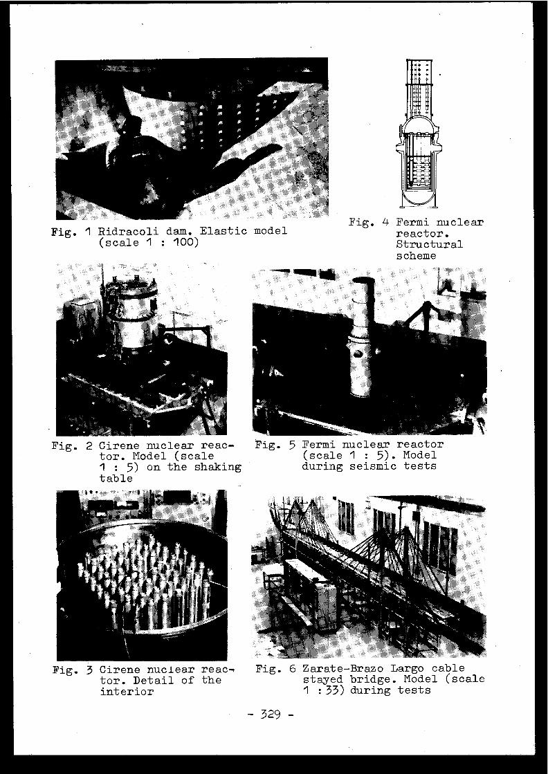
Fig. I Ridracoli dam . Elastic mode l(scale I : 100)
Fig . 4 Fermi nuclearreactor .Structuralscheme
Fig. 2 Cirene nuclear reac -tor . Model (scal eI : 5) on the shakingtable
Fig . 5 Fermi nuclear reactor(scale I : 5) . Modelduring seismic test s
Fig . 3 Cirene nuclear reac-tor. Detail of theinterior
Fig. 6 Zarate-Brazo Largo cablestayed bridge . Model (scal e1 :33) during test s
-329 -
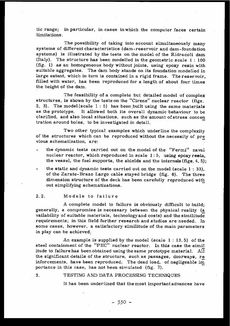
tic range ; in particular, in cases in which the computer faces certai nlimitations .
The possibility of taking into account simultaneously manysystems of different characteristics (dam-reservoir and dam-foundationsystems) is illustrated by the tests on the model of the Ridracoli da m(Italy) . The structure has been modelled in the geometric scale 1 : 10 0(fig . 1) as an homogeneous body without joints, using epoxy resin withsuitable aggregates . The dam body stands on its foundation modelled i nlarge extent, which in turn is contained in a rigid frame . The reservoir ,filled with water, has been reproduced for a length of about four time sthe height of the dam .
The feasibility of a complete but detailed model of comple xstructures, is shown by the tests on the " Cirene" nuclear reactor (figs .2, 3) . The model (scale 1 : 5) has been_built using the same materialsas the prototype . It allowed both its overall dynamic behaviour to b eclarified, and also local situations, such as the amount of stress conce ntration around holes, to be investigated in detail .
Two other typical examples which underline the complexityof the structures which can be reproduced without the necessity of previous schematization, are :
the dynamic tests carried out on the model of the "Fermi" navalnuclear reactor, which reproduced in scale 1 : 5, using epoxy resin,the vessel, the fuel supports, the shields and the internals (figs . 4, 5) ;
- the static and dynamic tests carried out on the model (scale 1 : 33) ,of the Zarate-Brazo Largo cable stayed bridge (fig . 6) . The thre edimension structure of the deck has been carefully reproduced without simplifying schematizations .
2 .2 .
Models to failur e
A complete model to failure is obviously difficult to build ;generally, a compromise is necessary between the physical reality (availability of suitable materials, technology and costs) and the similituderequirements ; in this field further research and studies are needed . Insome cases, however, a satisfactory similitude of the main parametersin play can be achieved :
An example is supplied by the model (scale 1 : 13 . 5) of thesteel containment of the "PEC" nuclear reactor . In this case the similitude to failure has been obtained using the same prototype material . Allthe significant details of the structure, such as passages, doorways, reinforcements, have been reproduced . The dead load, of negligeable importance in this case, has not been simulated (fig . 7) .
3 .
TESTING AND DATA PROCESSING TECHNIQUE S
It has been underlined that the most important advances hav e
- 330 -
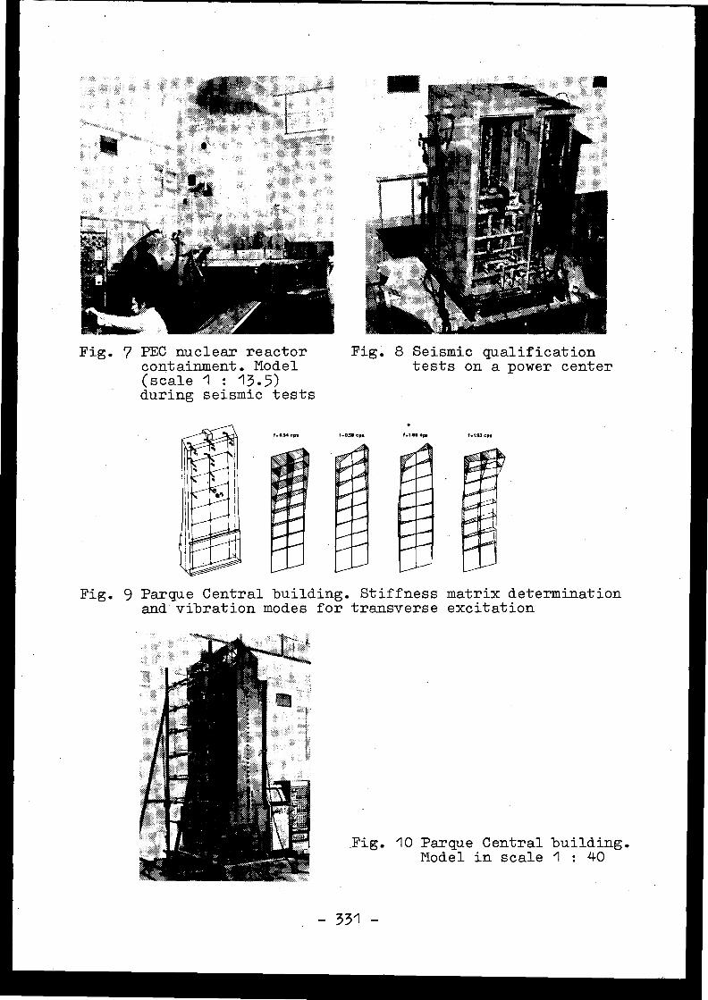
Fig. 8 Seismic qualificationtests on a power center
Fig . 7 PEC nuclear reactorcontainment . Mode l(scale 1 : 13 .5 )during seismic tests
V .1.00 o..
Fig . 9 Parque Central building . Stiffness matrix determinatio nand vibration modes for transverse excitatio n
Fig. 10 Parque Central building .Model in scale I : 40
- 331 -
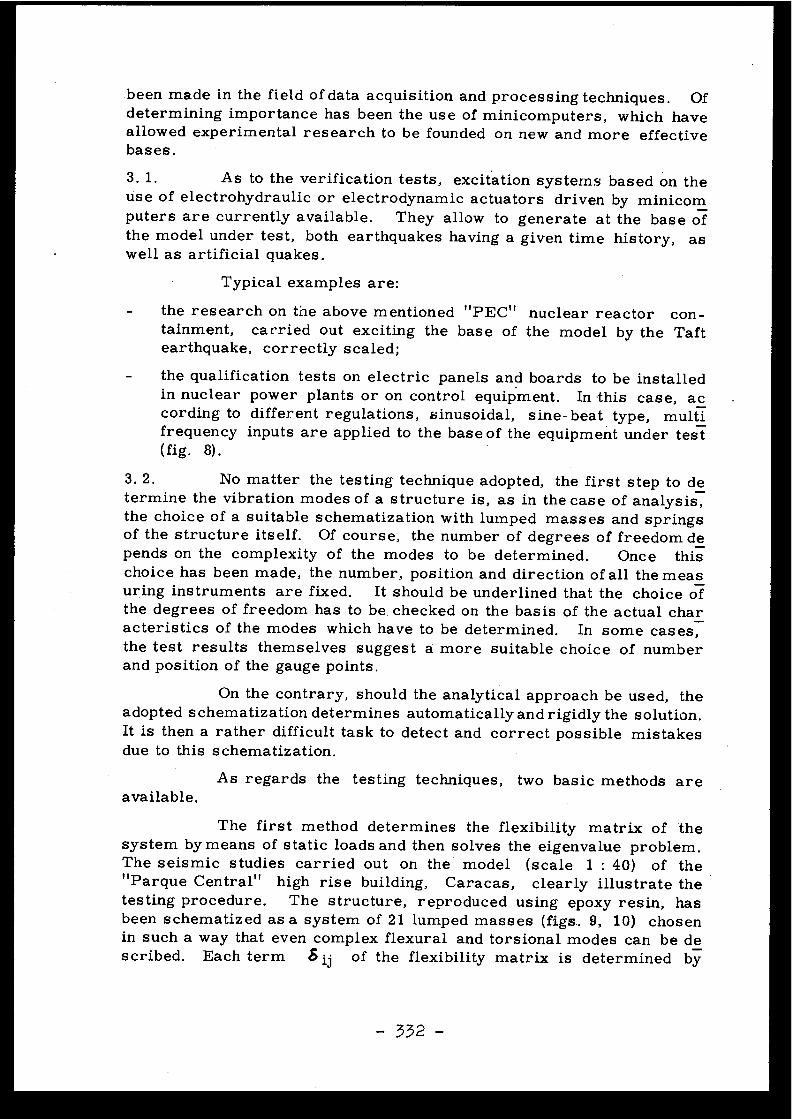
been made in the field of data acquisition and processing techniques . Ofdetermining importance has been the use of minicomputers, which hav eallowed experimental research to be founded on new and more effectiv ebases .
3 . 1 . As to the verification tests, excitation systems based on th elise of electrohydraulic or electrodynamic actuators driven by minico mputers are currently available. They allow to generate at the base o fthe model under test, both earthquakes having a given time history, a swell as artificial quakes .
Typical examples are :
- the research on the above mentioned "PEC" nuclear reactor
con -tainment,
carried out exciting the base of the model by the Taftearthquake, correctly scaled ;
- the qualification tests on electric panels and boards to be installedin nuclearcording tofrequency(fig .
8) .
power plants or on control equipment .
In-this case, acdifferent regulations, sinusoidal,
sine-beat . type,
multiinputs are applied to the base of the equipment under tes t
3 . 2 . No matter the testing technique adopted, the first step to determine the vibration modes of a structure is, as in the case of analysis ,the choice of a suitable schematization with lumped masses and spring sof the structure itself. Of course, the number of degrees of freedom depends on the complexity of the modes to be determined . Once thischoice has been made, the number, position and direction of all the mea suring instruments are fixed. It should be underlined that the choice ofthe degrees of freedom has to be . checked on the basis of the actual cha racteristics of the modes which have to be determined . In some cases,the test results themselves suggest a more suitable choice of numberand position of the gauge points .
On the contrary, should the analytical approach be used, theadopted s chematization determines automatically and rigidly the solution .It is then a rather difficult task to detect and correct possible mistake sdue to this schematization .
As regards the testing techniques, two basic methods ar eavailable .
The first method determines the flexibility matrix of th esystem by means of static loads and then solves the eigenvalue problem .The seismic studies carried out on the model (scale 1 : 40) of the" Parque Central " high rise building, Caracas, clearly illustrate thetesting procedure . The structure, reproduced using epoxy resin, hasbeen schematized as a system of 21 lumped masses (figs .. 9., 10) chosenin such a way that even complex flexural and torsional modes can be described . Each term .5 ij of the flexibility matrix is determined by
- 332 -
measuring the displacement qi induced by a . force Qj applied at point j :
Ô ij = g i/Qj
This procedure, theoretically simple, requires, however, a very larg enumber of measurements to be taken, as, in order to increase the r eliability of the $ ij coefficients, it is generally advisable to repeat, a teach measuring point, several loading cycles . By means of modern dataacquisition systems, the results are digitalized and sent to a compute rwhich arrays the flexibility matrix . During this phase the mean value sof the displacements obtained in the different cycles are computed, th esymmetries of the matrix (according to the Maxwell principle) and, ifany, of the structure, are checked. As the designer is directly concerne dwith the knowledge of the stresses induced by the- seismic forces, th ematrix which relates the external loads with the stresses in particularyimportant parts of the structure is determined simultaneously with th eflexibility matrix, using similar criteria .
The second method requires the structure is forced to vibrat eby a suitable system of forces, to make evident, in the structural r esponse, the modes of interest, the characteristics of which (frequency ,damping and shape) are obtained from the test results by means of prof •er processing techniques . The main advantage of this method, wit hrespect to the first (as well as to the analytical 'procedures), is that i tallows local vibrations (sometimes of great importance) to be discove red, which the overall schematization could miss . Besides, the proferties of the damping matrix can be obtained, and, hence, it is possibl eto check the assumption of the existence' of "normal" modes, or thenecessity of adopting " complex " modes . In the last few years tool shave become available (such as measurement transducers, data acquis ition and processing systems) which have made it possible to apply thi smethod in a fully satisfactory manner . Without going into details as totheoretical basis of the method, the two main techniques used are :
a) The model is excited by means of concentrated sinusoida lforces, acting in several points of the structure . Frequency, amplitudeand phase lag of each force are chosen in such a way as to excite a si ngle mode at a time, and to eliminate the contribution of the undesire dmodes . In such conditions, the measurement of the response acceler ations of the structure directly provides the modal shape, while the damEing coefficient can be obtained from the measurement of the input power .Moreover, by means of a suitable number of strain gauges, it is possibl eto determine the stress distribution corresponding to each mode . Theresearch carried out on the Ridracoli dam' is an example of this tec hnique. The schematization with 120 degrees of freedom has allowe dthe first six vibration modes to be detected, and their shapes and stres sdistribution to be described in detail (fig . 11) .
b) The test is carried out in two consecutive steps . During thefirst step the complex transfer function Hi (w) between the acceleration
- 333 -
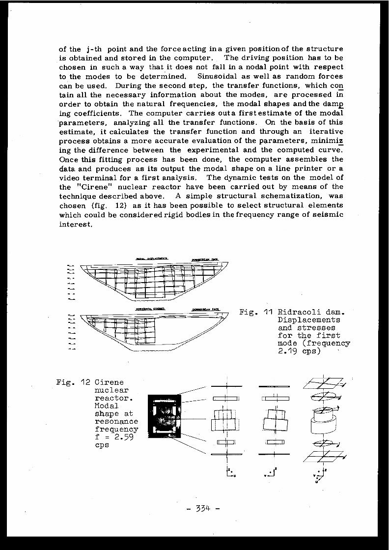
of the j-th point and the force acting in a given position of the structur eis obtained and stored in the computer . The driving position has to b echosen in such a way that it does not fall in a nodal point with respec tto the modes to be determined. Sinusoidal as well as random force scan be used. During the second step, the transfer functions, which contain all the necessary information about the modes, are processed i norder to obtain the natural frequencies, the modal shapes and the dam eing coefficients . The computer carries out a first estimate of the moda lparameters, analyzing all the transfer functions . On the basis of thi sestimate, it calculates the transfer function and through an iterativ eprocess obtains a more accurate evaluation of the parameters, minimi zing the difference between the experimental and the computed curve .Once this fitting process has been done, the computer assembles th edata and produces as its output the modal shape on a line printer or avideo terminal for a first analysis . The dynamic tests on the model ofthe " Cirene" nuclear reactor have been carried out by means of th etechnique described above . A simple structural schematization, waschosen (fig. 12) as it has been possible to select structural element swhich could be considered rigid bodies in the frequency range of seismi cinterest .
Fig . 11 Ridracoli dam .Displacementsand stresse sfor the firs tmode (frequency2 .19 cps )
Fur
Fig . 12 Cirenenuclearreactor .Modalshape atresonanc efrequencyf = 2 .59cp s
- 334 -
Only slight difference exists between the two methods jus tdescribed as to the first vibration modes ; as regards the more involve dhigher ones, the second method is more advantageous, owing to its easyapplicability.
3. 3 . The determination of the vibration modes, which is in anycase a rather involved job, can be by-passed by a very effective metho dof seismic verification which determines the transfer function betwee nthe response (accelerations, strains) in points of interest of the. structure, and the acceleration applied to the base of the model fixed on ashaking table. This method does not require complex exciting equipment ,as it is enough to apply an excitation of whatever characteristics . Besides, Wallows the response to any type of input motion to be obtained ina simple way, as given by the relatfariship :
qi (t) =
1 ( Hi ( w ) ' A ( 4)) )
where: A (w) is the Fourier transform of the input signal, and
- 1indicates the Fourier inverse transform algorithm .
4. CONCLUSIONS
On the basis of the considerations laid out above, the follow_ing conclusions can be drawn:
the experimental method is an effective tool as to the structural ve rification on models during the design stage . The same techniques ,used for in situ tests, allow the true characteristics of the actua lstructures to be determined, and a comparison with the compute d
data to be carried out ;
- within the elastic range, very accurate models and completely reliable results can always be obtained . The same accuracy can not b eexpected from the models to failure ; nonetheless, in a large numberof cases, they might contribute to the solution of very involved problems ;
- the main drawbacks which, in the past years, affected the expe rimental approach, have today been overcome. The results of thetests can be compared to those obtained by computing methods, evenfrom the point of view of their quantity;
- the cooperation between computer and model which is the basis ofthe most up to date testing techniques, could in future yield an inte rpretation of the experimental data through the automatic generationof suitable mathematical models .

Discussion s
D . COSTES, Franc e
L'ISMES a-t-il effectué des essais prenant e ncompte l'effet des séismes sur le sol ? Retrouve-t-on le srésultats des calculs concernant l ' interaction sol-structure ?
A . CASTOLDI, Italy
The tests carried out at ISMES on this subjectconcern mainly complex structures like dams ; in this parti-cular case, differences have been found between the computednatural frequencies of the structure and the experimentallydetermined values .
studied .Concerning buildings no significant cases have been
N.N . AMBRASEYS, United Kingdo m
Model testing is an ideal method for checking th etheories that describe the dynamic behaviour of the model . Doyou think that this method is describing the prototype beha -viour ? I agree that elements which do not lend themselve sto analytical consideration should be tested in a model form .
A . CASTOLDI, Italy
In my opinion, model testing isn't only an idealmethod for checking theories, but mainly a method to reproduc ethe prototype behaviour by bypassing theories . In fact, inderiving similitude laws for a certain physical phenomenon ,it is not necessary to know the theory beyond this phenomenon ;it is only necessary to know all the quantities involved i nthe problem . Concerning the simulation of the linear elasti cbehaviour of structures, the accuracy of the model is extre -mely high as shown by the comparison of experimental dat aobtained through models and testing the prototype structure .Model to failure, on the contrary, needs at the present tim emore research on materials .
A . ZELIKSON, Franc e
I have a completely different view on the subject ,as you will hear in a moment .

M. =VOLANT, Franc e
Lorsque vous avez testé des équipements complexes ,tels que des armoires électriques ou des tableaux de contrôle ,avez-vous vu la nécessité d'utiliser une excitation simultané edans les directions horizontales et verticales ?
A .CASTOLDI, Italy
A certain coupling between horizontal and vertica lmotion, which is always present in the response of the elec -trical boards and the strongly non linear behaviour of thes estructures at high acceleration level, may in principle requirethe use of equipment capable of generating motions in twodirections .
From a practical point of view however, I believ ethat the high cost of an extremely complex testing equipmentcannot be justified, especially taking into account the uncer -tainties connected with the determination of floor respons espectra .
E . ROBERT, France
Ma question n'est pas de sûreté nucléaire .
A-t-on fait à Bergame des essais sismiques concernantun barrage avec eau à l'amont ?
Je présume que la réponse est négative .
A.CASTOLDI, Italy
Tests on dams have been carried out with water o nthe reservoir only when the natural modes of vibration wer eto be determined . In this case, in fact, also a "distorted "model which does not reproduce the real load and the hydro -static pressure is adequate .
Concerning failure tests, special heavy liquids havebeen used to simultaneously simulate hydrostatic and hydro -dynamic effects .
[5 .2]
ESSAI SUR TABLE VIBRANTE D'UN COEUR DE REACTEURA HAUTE TEMPERATURE
COMPARAISON AVEC LES RESULTATS OBTENUS A L'AID ED'UN MODET1E MATHEMATIQUE NON LINEAIRE
C .Berriaud, E .Cèbe, M .Livolant - Département des Etude sMécaniques et Thermiques - CEA-Centre d'Etudes Nucléaires deSaclay - Gif sur Yvette - Franc e
P .Buland - Sté Métravib - Ecully Franc e
Résumé
Deux séries d'essais ont été réalisées à Saclay sur la tabl evibrante horizontale VESUVE : Essais sinusoïdaux et reproduc-tion de séismes.
Les essais sinusoïdaux ont montré le comportement no nlinéaire du coeur : La fréquence de résonance varie avec le ni-veau d'excitation . Ce phénomène est expliqué par les résultat sobtenus à l'aide d'un code de calcul dans lequel le coeur estconsidéré comme une masse unique se déplaçant entre deux bu-tées .
Le déplacement correspondant à celui de la base d ucoeur dans le cas d'un séisme identique à celui d'El Centro aété reproduit sur la table vibrante . Le calcul correspondan ta été fait avec le modèle analytique et une bonne concordanc ea été obtenue pour les forces et les vitesses .
Summary
Two series of horizontal tests have been performed at Saclayon the shaking table VESUVE : sinusoïdal test and time historyresponse .
Sinusoïdal tests have shown the strongly non-linea rdynamic behaviour of the core . The resonant frequency of th ecore is dependent on the level of the excitation .These pheno-mena have been explained by a computer code,which is a lumpedmass non linear model .
El Centro time history displacement at the level o fPCRV was reproduced on the shaking table . The analytical mode lwas applied to this excitation and good comparison was obtainedfor forces and velocities .
- 338 -
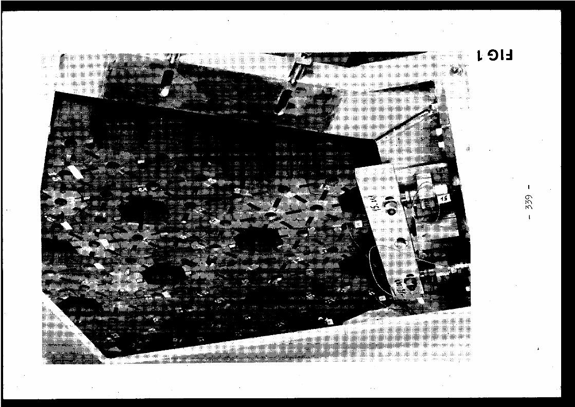
L Old
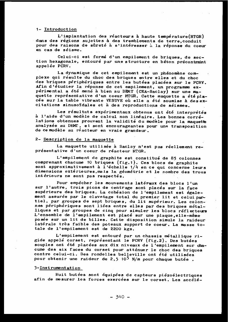
1- Introduction
L'implantation des réacteurs à haute température(HTGR )dans des régions sujettes à des tremblements de terre,conduitpour des raisons de sûreté à s'intéresser à la réponse du coeuren cas de séisme .
Celui-ci est formé d'un empilement de briques, de sec-tion hexagonale, entouré par une structure en béton précontraintappelée PCRV .
La dynamique de cet empilement est un phénomène com-plexe qui résulte du choc des briques entre elles et du cho cdes briques périphériques entre les butées placées sur le PCRV .Afin d'étudier la réponse de cet empilement, un programme ex-périmental a été mené à bien au DEMT (CEA-Saclay) sur une ma-quette représentative d'un coeur HTGR . Cette maquette a été pla-cée sur la table vibrante VESUVE où elle a été soumise à des ex-citations sinusoidales et à des reproductions de séismes .
Les résultats expérimentaux obtenus ont été interprété sà l'aide d'un modèle de calcul non linéaire . Les bonnes corré-lations obtenues prouvent la validité du modèle pour la maquett eanalysée au DENT, et sont encourageantes pour une transpositio nde ce modèle au réacteur en vraie grandeur .
2-Description de la maquett e
La maquette utilisée à Saclay n'est pas réellement re-présentative d'un coeur de réacteur HTGR .
L'empilement de graphite est constitué de 85 colonne scomprenant chacune 10 briques (fig .1) . Ces blocs de graphit esont approximativement à l'échelle 1/4 en ce qui concerne leur sdimensions extérieures,mais la géométrie et le nombre des trou sintérieurs ne sont pas respectés .
Pour empécher les mouvements latéraux des blocs l'unsur l'autre, trois pions de centrage sont placés sur la fac esupérieure des briques . La cohésion de l'empilement est égale -ment assurée par le clavetage total du premier lit et celui par -tiel, par groupes de sept briques, du lit supérieur . Les colon-nes périphériques sont liées entre elles par des briques métal-liques et par groupes de cinq pour simuler les blocs réflecteur sL'ensemble de l'empilement est placé sur une plaque,elle-mêmeposée sur un lit de billes . Cette disposition simule la raideurlatérale très faible des poteaux support de coeur . La masse to-tale de l'empilement est de 2200 kgs .
L'empilement est entouré par un chassis métallique ri-gide appelé corset, représentant le PCRV (fig .2) . Des butée ssouples ont été placées aux dix niveaux de l'empilement sur cha-cune des six faces du corset pour atténuer le choc des brique scontre celui-ci . Des rondelles belleville ont été utilisée spour obtenir une raideur de 2,5 10 5 N/m pour chaque butée .
3-Instrumentation
Huit butées sont équipées de capteurs piézoélectrique safin de mesurer les forces exercées sur le corset . Les accélé -
- 340 -
FIG 2- 341 -
rations de vingt briques peuvent être enregistrées de manièreà déterminer les valeurs pics et à observer la propagation de schocs dans l'empilement .
Des capteurs de vitesse et de déplacement permetten td'obtenir le mouvement relatif entre le corset et l'empilement .
4- Réponse à une excitation sinusoîdal e
4-1 Résultats expérimentaux
Deux types d'essais horizontaux et unidirectionnelsont été effectués : des points fixes en fréquence à accéléra -tion constante, des balayages à déplacement constant .
4-1-1
Accélération constant e
4-1-1-1
Force s
La courbe de réponse de force pour un niveau d'excita-tion de 0,2 g,présente un aspect non linéaire avec un phénomènede saut caractéristique (fig .3) . La fréquence de résonance d el'empilement qui est de 4 Hz pour 0,2 g croit avec le niveaud'excitation ,sante .
ce qui est typique d'un ressort à raideur crois-
Les forces sur les butées atteignent 2000 N (0,2 g) e nhaut de l'empilement et sont nettement plus faibles dans lapartie basse de celui-ci .
Les signaux de force sont en forme de demi-sinus,c equi est à rapprocher du schéma classique d'une masse tombantsur un ressort .
4-1-1-2 Déplacements et vitesse s
La fréquence de résonance et le phénomène de saut sontaussi détectés à l'aide des capteurs de déplacement . Ceux-c ipermettent par ailleurs d'évaluer la compression des butées aucours des chocs .
Les vitesses atteintes par les blocs périphériques sontrelativement faibles : 0,3 m/s pour 0,2 g à la résonance et n esemblent pas être dangereuses pour la bonne tenue des briques .
4-1-1-3 Temps de contact de l'empilement sur le corse t
Ce temps de contact est décroissant avec la période d el'excitation et est inférieur à la demi période (fig .5) . Cecimet donc en évidence un temps de transfert de l'empilementd'une butée à la butée opposée .
Période del'excitation
Temps decontact
Temps detransfert
3 Hz 332 ms 121
ms 45 ms
3,5 Hz 2 85 ms 113 ms 29 ms
4 Hz 252 ms 96 ms 29 ms
- 342 -
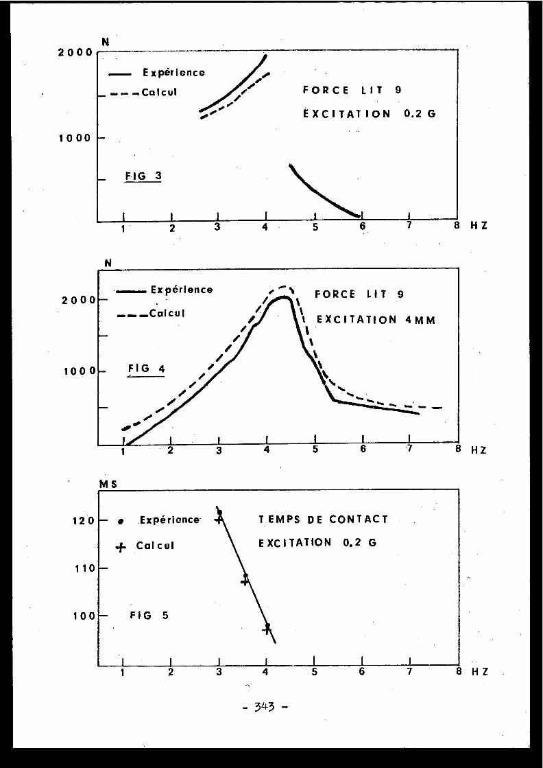
N
/
FORCE LIT 9i
EXCITATION 0 .2 G
Expérienc e
-Calcu l
FIG3
200 0
1000
2 8 H Z
N
1
2000
100 0
120
MS
- • Expérience- -~ TEMPS D E CONTAC T
+ Calcu l
110
EXCITATION 0.2 G
100 - FIG .5
I
I
i I l2
3
4
5
6 8 H Z
- 343 -
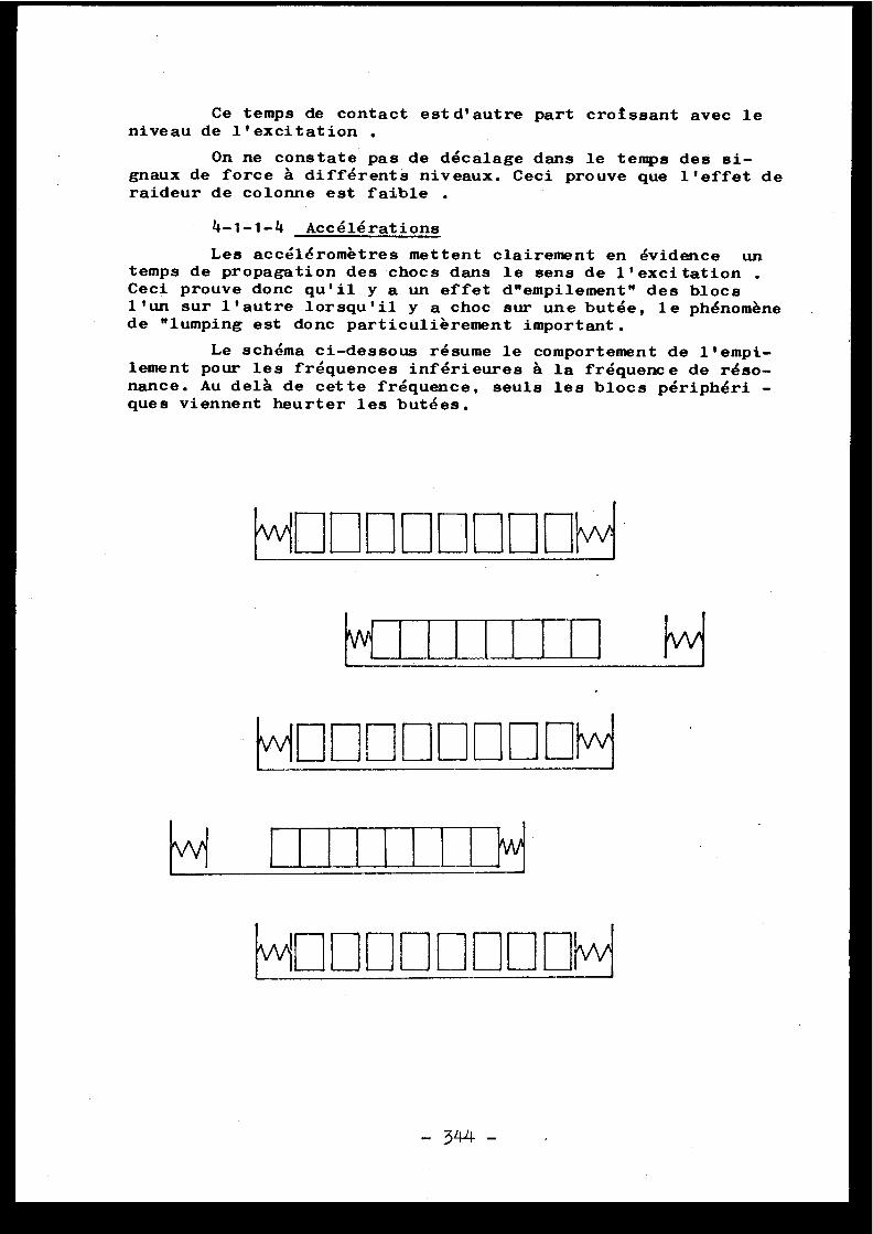
Ce temps de contact est d'autre part croissant avec leniveau de l'excitation .
On ne constate pas de décalage dans le temps des si-gnaux de force à différents niveaux . Ceci prouve que l'effet deraideur de colonne est faible .
4-1-1-4 Accélération s
Les accéléromètres mettent clairement en évidence untemps de propagation des chocs dans le sens de l'excitation .Ceci prouve donc qu'il y a un effet d"empilement" des bloc sl'un sur l'autre lorsqu'il y a choc sur une butée, le phénomènede "lumping est donc particulièrement important .
Le schéma ci-dessous résume le comportement de l'empi-lement pour les fréquences inférieures à la fréquence de réso-nance . Au delà de cette fréquence, seuls les blocs périphéri -ques viennent heurter les butées .
w
w
w
L
F-1
w
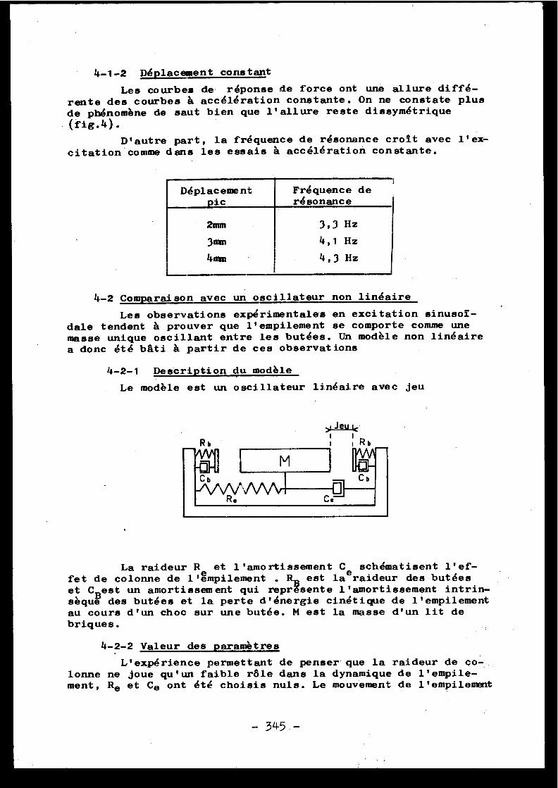
4-1-2 Déplacement constant
Lea courbes de réponse de force ont une allure diffé-rente des courbes â accélération constante . On ne constate plusde phénomène de saut bien que l'allure reste dissymétrique
(fig .4) .
D'autre part, la fréquence de résonance croit avec l'ex-
citation ' comme dans les essais â accélération constante .
Déplacement Fréquence d e-_pic résonanc e
2mm 3,3 Hz
3mm 4,1 Hz
4mm 4,3 Hz
4-2 Comparaison avec un oscillateur non linéair e
Les observations expérimentales en excitation sinusol-dale tendent â prouver que l'empilement se comporte comme un emasse unique oscillant entre les butées . Un modèle non linéairea donc été bâti â partir de ces observation s
4-2-1 Description du modèl e
Le modèle est un oscillateur linéaire avec je u
La raideur R et l'amortissement C e schématisent l'ef-fet de colonne de l'émpilement . Rn est laraideur des butée set CBest un amortissement qui reprësente l'amortissement intrin -sèque des butées et la perte d'énergie cinétique de l'empilemen tau cours d'un choc sur une butée . M est la masse d'un lit d ebriques .
4-2-2 Valeur des paramètre s
L'expérience permettant de penser que la raideur de co-lonne ne joue qu'un faible râle dans la dynamique de l'empile -ment, Re et Ce ont été choisis nuls . Le mouvement de L'empilement
- 345 . -
est donc traité comme un phénomène plan . M est la masse d'unlit & l'empilement : M = 240 kg . RR est la raideur d'une butée ;l'influence des butées latérales 'est pas prise en compte :RB= 2,5 105 N/m .
Il est impossible de connattre l'amortissement à priori ,deux valeurs ont été essayées : 10 % et 20%, soit :
CB = 1550 M/ms- 1
CB = _3100 >1/ms- 1
le jeu total est égal à 6m m
4-2-3 Comparaison: Accélération constant e
La courbe de réponse de la force exercée sur les butéesest tout à fait semblable à l'expérience( fig .3) . Au delà de4 Hz (0,2 g) i.e modèle ne tend pas vers une solution stable,c equi explique le phénomène de saut des courbes expérimentales .L'amortissement _de 20% donne les meilleurs résultats pour le sniveaux de force . Le temps de contact de l'empilement sur le sbutées est bien retrouvé par le calcul (fig .5 )
4-2-4 Comparaison: Déplacement constant
La comparaison expérience calcul a été effectuée pourun déplacement de 4mm (pic) . La fréquence de résonance est trè sbien retrouvée (4,25 Hz) et l'allure de la courbe de réponse desforces présente le même aspect dissymétrique que par l'expérien -ce (fig .4) . Le niveau des forces est bien respecté pour un amor -tissement de 20% .
5- Tests et calculs sismique s
Le séisme reproduit sur la table vibrante VESUVE es tcelui d'El Centro N .S .(0,3482 g au niveau du sol) transposé a univeau du PCRV (fig .6) . Compte tenu des possibilités de la tabl evibrante, ce séisme a été transposé à l'échelle 1/2 dans une si-militude de vitesse . La comparaison expérience calcul a port éessentiellement sur les forces conservant les mêmes valeurs de sparamètres que pour le calcul sinusoidal sauf pour l'amortisse-ment des butées qui est de 139 (fig .7 et 8) .
Les forces exercées sur le corset sont bien retrouvée spar le calcul aussi bien en amplitude que dans le temps . Onconstate que celles-ci sont maximum au début du séisme et attei-gnent 4000 N sur une butée .
Le calcul permet aussi de retrouver la vitesse maximumd'impact de l'empilement atteinte, 1,23 s après le début du séis -me . Celle ci est de 760 mm/s par le calcul et 745 mm/s par l'ex-périence .
6- Conclusion
L'étude effectuée au DEMT a montré qu'un modèle simpl epouvait parfaitement rendre compte du comportement dynamiqued'un empilement HTGR . Ce modèle étant valable aussi bien pou rune excitation sinusoîdale que pour une excitation sismique .
- 346 -
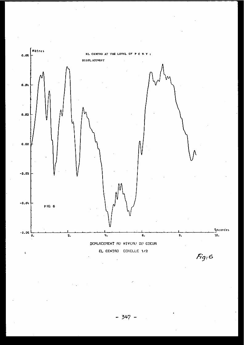
Métre s0 .06 EL. CENPRO AT THE LEVIL OF P C R V
DISPLACEMENT
0 .04
A
0 .02
0 .00
r
-0.02
-0.04FIG 6
-0 .06 1 I L Sleconde s
0 .
2 .
4 .
6 .
9 .
10 .
OEPLACEMENT RU NIVEAU OU COEU R
EL CENTRO ECIIELLE 1/2
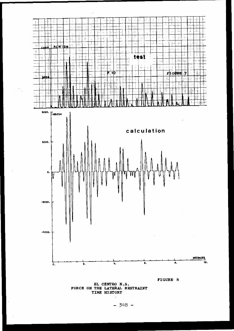
II =EMI Mar=- MIME
ENE EN® ®®®®®®®~ 01IMILM111MOWIMM119 II
mmirt riiui.INIMMMINNIMENINNEEj
IIIA ®
MB_®®®tII I111 0T MINMINIMIMI .
1®
4000 . rNCN70N
calculatio n2000 .
o ._ Y r -11
{
{
-1000 .
I
1
{

Il a permis d'expliquer les phénomènes non linéaire srencontrés au cours des essais et de prouver que le mouvemen tde'l'empilement pouvait être traité uniquement dans le plan .
Les bonnes corrélations entre l'expérience et le cal -cul obtenues pour les forces appliquées au PCRV et les vites -ses de choc des blocs périphériques sur les butées prouvent l avalidité du modèle .
La transposition éventuelle du modèle au réacteur e nvraie grandeur pose toutefois le problème de l'évaluation cor-recte de l'amortissement . En effet une estimation erronée d ecelui-ci pourrait conduire è des erreurs importantes sur le sforces et les vitesses . Ce n'est qu'après la détermination cer-taine de ce paramètre que la sûreté sismique du coeur des ré -acteurs HTGR pourra être assurée .

Discussion s
J .C . TIFFEVRE, France
On peut penser, pour expliquer le phénomène d esaut dans la réponse pour une excitation à fréquence variable ,observé expérimentalement, à l'intervention d'un frottementsec de type coulombien entre les blocs de graphite superposés .Le comportement instable observé serait alors bien représent épar la solution d'une équation de Mathieu . Ma question est :"A-t-on mis en évidence au cours des essais des mouvement srelatifs de glissement des blocs superposés, de nature. àfaire intervenir de façon significative le frottement cou-lombien ?" .
C . BERRIAUD, Franc e
Dans chaque colonne les briques sont positionnée sles unes sur les autres au moyen de trois pions s'engagean tdans les trous de la brique supérieure . Il ne peut donc yavoir de glissement sensible d'une brique sur l'autre .
[5 .3 ]
MODÈLES RÉDUITS POUR L ' ÉTUDE DE L ' INTERACTION
STRUCTURES-SOL S
PENDANT LES TREMBLEMENTS DE TERR E
------------------------------------------- -
A . ZELIKSON
ECOLE POLYTECHNIQUE-ECOLE NATIONALE SUPERIEURE DES MINES DE PARI S
LABORATOIRE DE MECANIQUE DES SOLIDES
EQUIPE DE RECHERCHE ASSOCIEE AU C .N .R .S .
Mule :
L'article traite des problèmes de réalisation des conditions de similitud epour les problèmes de tremblements de terre, compte tenu des trois échelle sdifférentes pour le temps, «es à l'inertie, la liquéfaction et la viscosité .
Les méthodes de centrifugation du gradient hydraulique et du sable a deux di-
mensions sont comparées entre elles . Des améliorations de la méthode du sabl eà deux dimensions, pour tenir compte de la viscosité, sont présentées .
Synap4iJ.
The paper deals with scale modelling for earthquake problems, taking in ac-count the three different time scales according to inertia, liquification an dviscosity .
The methods of centrifugation,hydraulic gradient and two dimensional sand ar ecompared to each other . Improvements to the method of two dimensional sand are
.
presented in order to take care of the influence of viscosity .
--------------------------------
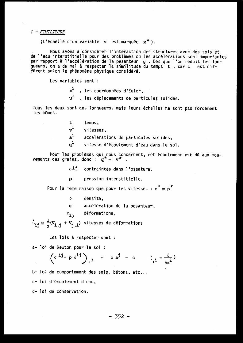
1 - SIMILITUDE
(L'échelle d'un variable x est marquée x*) .
Nous avons à considérer l'intéraction des structures avec des sols e tde l'eau interstitielle pour des problèmes où les accélérations sont importante spar rapport à l'accélération de la pesanteur g . Dès que l'on réduit les lon-gueurs, on a du mal à respecter la similitude du temps t , car t est dif-férent selon le phénomène physique considéré .
Les variables sont :
xi , les coordonnées d'Euler ,
ul , les déplacements de particules solides .
Tous les deux sont des longueurs, mais leurs échelles ne sont pas forcémen tles mêmes .
t temps ,
3 vitesses ,
al
accélérations de particules solides ,
ql
vitesse d'écoulement d'eau dans le sol .
Pour les problèmes qui nous oncernent, cet écoulement est dû aux mou-vements des grains, donc : q = Ir* .
a i l contraintes dans l'ossature ,
p
pression interstitielle .
Pour la même raison que pour les vitesses : a = p'
p
densité ,
g accélération de la pesanteur ,
cil
déformations ,
ei7= 2(
+ V) ,i) vitesses de déformation s
Les lois à respecter sont :
a- loi de Newton pour le sol :
( c ii + p
Sii l ) 1. + p ai = o
( i = a )/
axl
b- loi de comportement des sols, bétons, etc . . .
c- loi d'écoulement d'eau ,
d- loi de conservation .
- 352 -
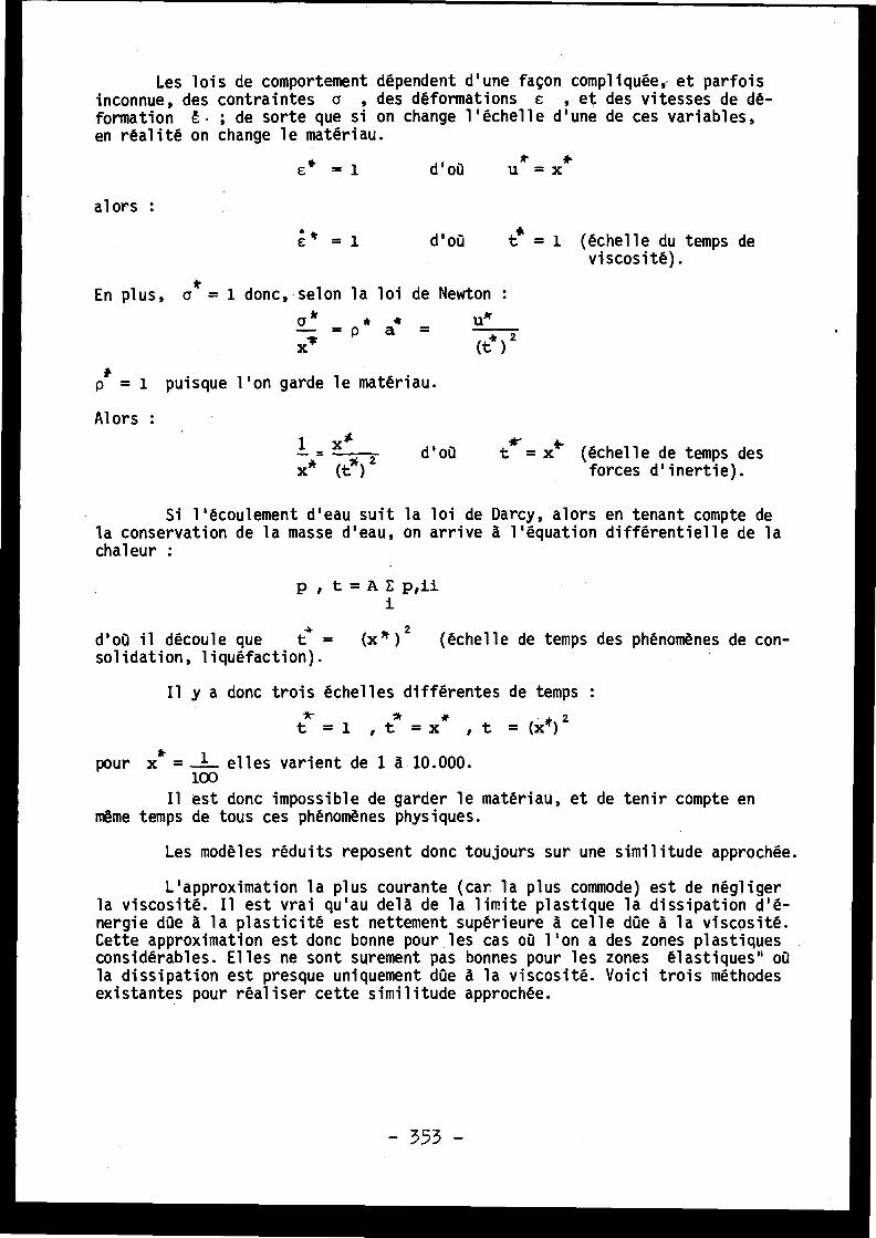
Les lois de comportement dépendent d'une façon compliquée, et parfoi sinconnue, des contraintes a , des déformations s , et des vitesses de dé-formation t . ; de sorte que si on change l'échelle d'une de ces variables ,en réalité on change le matériau .
e * = 1 d ' où u = x
alors
:
s
= 1 d'où t* = 1 (échelle du temps de
En plus,
viscosité) .
a* = 1 donc, selon la loi de Newton
a k
*
*
u~x~ = p a =
(t.'' )
2
p* = 1 puisque l'on garde le matériau .
Alors :
1
x*
91.d'où
t = x (échelle de temps de sx* (t" ) 2
forces d'inertie) .
Si l'écoulement d'eau suit la loi de Darcy, alors en tenant compte dela conservation de la masse d'eau, on arrive à l'équation différentielle de l achaleur :
p , t = A E p,iii
d'où il découle que
t =
(x *) 2
(échelle de temps des phénomènes de con-solidation, liquéfaction) .
Il y a donc trois échelles différentes de temp s
t =1 ,t =x* ,t =(x*) 2
pour x* = 1 elles varient de 1 à 10 .000 .100
Il est donc impossible de garder le matériau, et de tenir compte e nmême temps de tous ces phénomènes physiques .
Les modèles réduits reposent donc toujours sur une similitude approchée .
L'approximation la plus courante (car la plus commode) est de néglige rla viscosité . Il est vrai qu'au delà de la limite plastique la dissipation d'é -nergie dùe à la plasticité est nettement supérieure à celle dùe à la viscosité .Cette approximation est donc bonne pour les cas où l'on a des zones plastique sconsidérables . Elles ne sont surement pas bonnes pour les zones élastiques" o ùla dissipation est presque uniquement dùe à la viscosité . Voici trois méthode sexistantes pour réaliser cette similitude approchée .
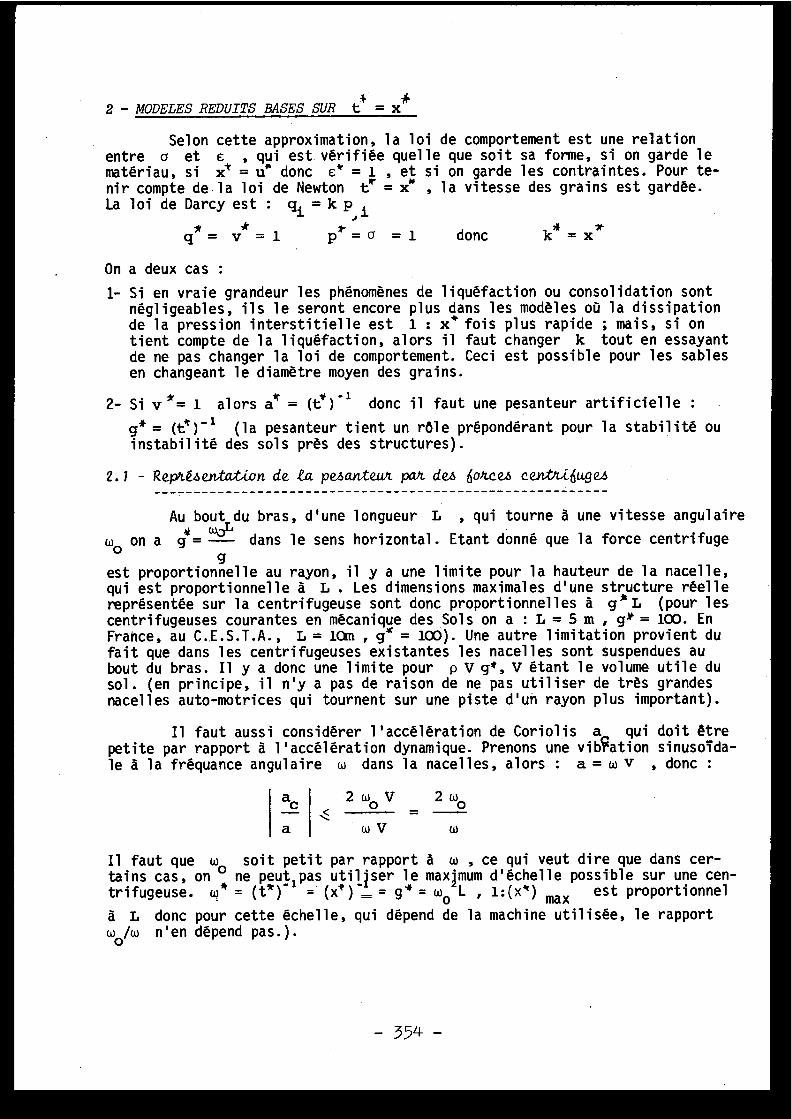
2 - MODELES REDUITSBASES SURt=x
Selon cette approximation, la loi de comportement est une relatio nentre c et e , qui est. vérifiée quelle que soit sa forme, si on garde l ematériau, si x'' = u* donc e* = 1 , et si on garde les contraintes . Pour te-nir compte de la loi de Newton te' = x" , la vitesse des grains est gardée .La loi de Darcy est : qi = k p i
q* = v = 1
p~ = a = 1
donc
k' = x *
On a deux cas :
1- Si en vraie grandeur les phénomènes de liquéfaction ou consolidation sontnégligeables, ils le seront encore plus dans les modèles où la dissipationde la pression interstitielle est 1 : x * fois plus rapide ; mais, si ontient compte de la liquéfaction, alors il faut changer k tout en essayan tde ne pas changer la loi de comportement . Ceci est possible pour les sablesen changeant le diamètre moyen des grains .
2- Si v *= 1 alors â = (t*r 1 donc il faut une pesanteur artificielle :
g* = (ti )" 1 (la pesanteur tient un rôle prépondérant pour la stabilité o uinstabilité des sols près des structures) .
2 . 1 - Rep' 4e.nta .iDn de ta pe6anteux pan deys 6oxces cen-tti6ugez-------------------------------------------------------- -Au bout du bras, d'une longueur L , qui tourne à une vitesse angulair e
wo on a g =- dans le sens horizontal . Etant donné que la force centrifuge
2 ô V
2 w0
=wV
w
Il faut que w_ soit petit par rapport à w , ce qui veut dire que dans cer-tains cas, on 0 ne peut pas utiliser le maximum d'échelle possible sur une cen-trifugeuse . w* = (te ) '
(x*) _ = g' = w o L , 1 :(e) max est proportionne l
à L donc pour cette échelle, qui dépend de la machine utilisée, le rapportô/w n'en dépend pas .) .
gest proportionnelle au rayon, il y a une limite pour la hauteur de la nacelle ,qui est proportionnelle à L . Les dimensions maximales d'une structure réell ereprésentée sur la centrifugeuse sont donc proportionnelles à g * L (pour lescentrifugeuses courantes en mécanique des Sols on a : L = 5 m , gx = 100. EnFrance, au C . .E .S .T .A ., L = 10nn , e = 100) . Une autre limitation provient dufait que dans les centrifugeuses existantes les nacelles sont suspendues a ubout du bras . Il y a donc une limite pour p V g*, V étant le volume utile du
sol . (en principe, il n'y a pas de raison de ne pas utiliser de très grande snacelles auto-motrices qui tournent sur une piste d'un rayon plus important) .
Il faut aussi considérer l'accélération de Coriolis a qui doit êtrepetite par rapport à l'accélération dynamique . Prenons une vibration sinusoida-le à la fréquance angulaire w dans la nacelles, alors : a = w v , donc :
ao
a
- 354 -
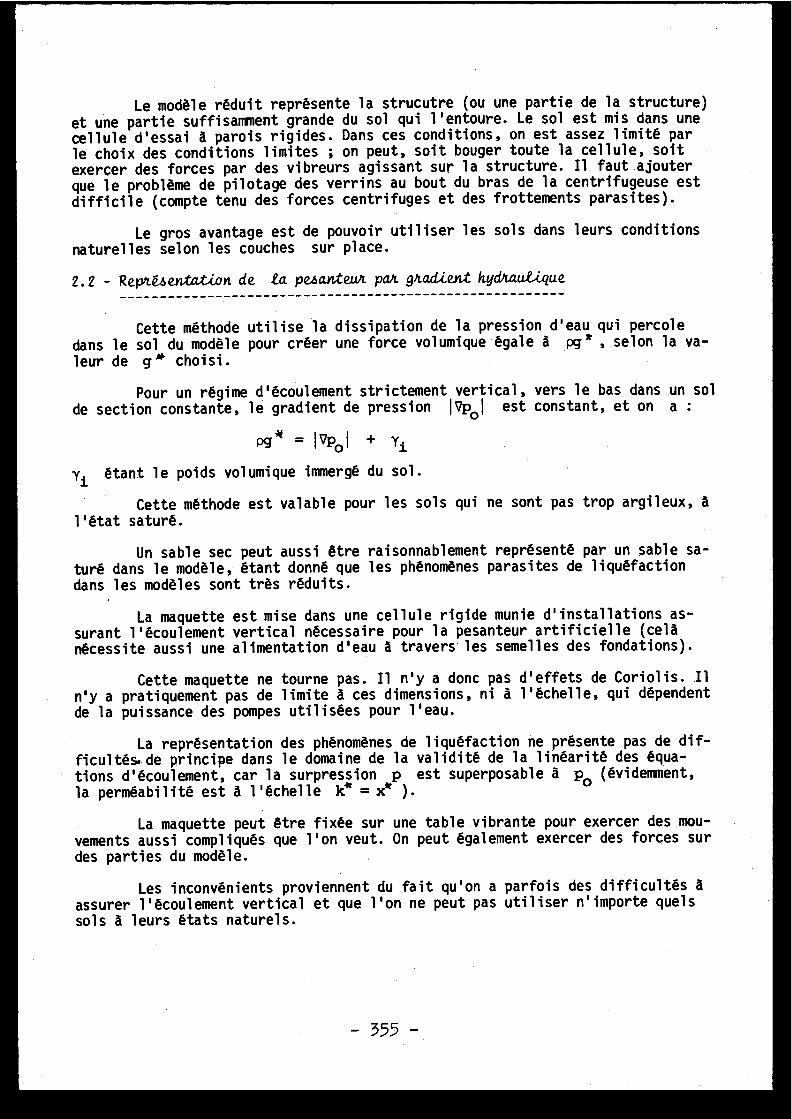
Le modèle réduit représente la strucutre (ou une partie de la structure )et une partie suffisamment grande du sol qui l'entoure . Le sol est mis dans unecellule d'essai à parois rigides . Dans ces conditions, on est assez limité pa rle choix des conditions limites ; on peut, soit bouger toute la cellule, soi texercer des forces par des vibreurs agissant sur la structure . Il faut ajouterque le problème de pilotage des verrins au bout du bras de la centrifugeuse es tdifficile (compte tenu des forces centrifuges et des frottements parasites) .
Le gros avantage est de pouvoir utiliser les sols dans leurs conditionsnaturelles selon les couches sur place .
2 .2 - Repké4 e vtav ion de ta pesanteur pan gna,d..i en t hydnau .que------------------------------------------------------- -
Cette méthode utilise la dissipation de la pression d'eau qui percol edans le sol du modèle pour créer une force volumique égale à pg k , selon la va-leur de g * choisi .
Pour un régime d'écoulement strictement vertical, vers le bas dans un so lde section constante, le gradient de pression IVpo l est constant, et on a :
Pg = I opol + Yl
Yi étant le poids volumique immergé du sol .
Cette méthode est valable pour les sols qui ne sont pas trop argileux, àl'état saturé .
Un sable sec peut aussi être raisonnablement représenté par un sable sa -turé dans le modèle, étant donné que les phénomènes parasites de liquéfactio ndans les modèles sont très réduits .
La maquette est mise dans une cellule rigide munie d'installations as -surant l'écoulement vertical nécessaire pour la pesanteur artificielle (cel anécessite aussi une alimentation d'eau à travers les semelles des fondations) .
Cette maquette ne tourne pas . Il n'y a donc pas d'effets de Coriolis . I1n'y a pratiquement pas de limite à ces dimensions, ni à l'échelle, qui dépenden tde la puissance des pompes utilisées pour l'eau .
La représentation des phénomènes de liquéfaction ne présente pas de dif -ficultés.de principe dans le domaine de la validité de la linéarité des équa -tions d'écoulement, car la surpression p est superposable à p (évidemment ,
la perméabilité est à l'échelle k* = x* ) .
°
La maquette peut être fixée sur une table vibrante pour exercer des mou -
vements aussi compliqués que l'on veut . On peut également exercer des forces sur
des parties du modèle .
Les inconvénients proviennent du fait qu'on a parfois des difficultés àassurer l'écoulement vertical et que l'on ne peut pas utiliser n'importe quel ssols à leurs états naturels .
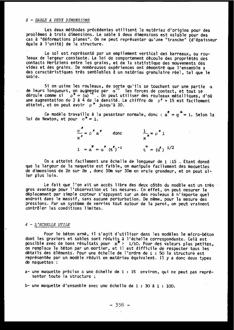
3 - SABLE A DEUX DIMENSIONS
Les deux méthodes précédentes utilisent le matériau d'origine pour de sproblèmes à trois dimensions . Le sable à deux dimensions est valable pour de scas à "déformations planes" . On ne peut représenter qu'une "tranche" (d'épaisseu régale à l'unité) de la structure .
Le sol est représenté par un empilement vertical des barreaux, ou rou-leaux de largeur constante . La loi de comportement découle des propriétés de scontacts Hertziens entre les grains, et de la statistique des mouvements de svides et des grains . De nombreuses expériences ont démontré que l'ensemble ades caractéristiques très semblables à un matériau granulaire réel, tel que l esable .
Si on usine les rouleaux, de sorte qu'ils se touchent sur une partie ade leurs longueurs, on augmeçte par a
les forces de contact, et tout s edéroule comme si
p* = (a) - . On peut utiliser des rouleaux métalliques, d'o ùune augmentation de 3 à 4 de la densité . Le chiffre de p* = 15 est facilemen tatteint, et on peut avoir p * jusqu'à 30 .
Ce modèle travaille à la pesanteur normale, donc : a* = g$= 1. Selon l aloi de Newton, et pour a* = 1 .
-= pa
donc
1 = p 1x
1 =â =u (t)-i
t = (u) 1/2
On a atteint facilement une échelle de longueur de 1 :15 . Etant donnéque la largeur de la maquette est faible, on manipule facilement des maquette sde dimensions de 2m sur 2m , donc 30m sur 30m en vraie grandeur, et on peut al -ler plus loin .
Le fait que l'on ait un accès libre des deux côtés du modèle est un trè sgros avantage pour l'observation et les mesures . En effet, on peut mesurer l edéplacement par simple capteur s'appuyant sur un des rouleaux à n'importe que lendroit dans le massif, sans aucune perturbation . De même, pour la mesure de spressions . Par un système de verrins tout autour de la paroi, on peut vraimen tcontrôler les conditions limites .
4 - L'ECHELLE UTILE
Pour le béton armé, il s'agit d'utiliser dans les modèles le micro-béto ndont les graviers et sables sont réduits à l'échelle correspondante . Celà estpossible avec de bons résultats pour x* > 1/10 . Pour des valeurs plus petites ,on remplace le béton par un mortier, et il est difficile de respecter tous le sdétails des éléments . Pour une échelle de l'ordre de 1 : 50 la structure estreprésentée par un modèle réduit en matériau équivalent . Il y a donc deux. typesde maquettes :
a- une maquette précise a une échelle de 1 : 15 environ, qui ne peut pas repré-senter toute la structure ;
b- une maquette d'ensemble avec une échelle de 1 : 30 à 1 : 100.
- 356 -
Là où l'échelle de vitesse est gardée (centrifugeuse et gradient hydrau -lique)
(~)
= (x )- 1
de sorte gue la part de contraintes dues à la viscosité linéaire est augmenté epar (x*)_
dans le modèle . Dans les modèles de sable à deux dimensions, ce scontraintes sont plus faibles, car tx =
=
. Les accélérations de Corio-
lis sont plus petites pour g» petits .
Pour tenir compte de la liquéfaction, il faut réduire la perméabilité ,c'est-à-dire le diamètre moyen des grains . Ceci est possible si l'échelle n'es tpas trop grande .
On voit bien que l'échelle utile est de l'ordre de 1 : 15 , et qu'i lsera nécessaire d'avoir les moyens de manipuler de grosses maquettes .
5 - LA STABILITE DES SOLUTIONS
Dans un modèle réduit, on contrôle le déroulement de l'expérience pa rl'intermédiaire des conditions initiales, et conditions limites que l'on impo-se . Celles-ci sont parfois données approximativement . La question de la stabi-lité est, d'après Hadamard, de savoir si la solution (ou l'expérience dans no-tre cas) dépend d'une façon continue (et unique) des conditions imposées . Sinon ,le fait de ne pas avoir dans le modèle exactement les mêmes conditions qu'e nvraie grandeur se traduira par une expérience en Laboratoire qui différera con-sidérablement du prototype .
Prenons comme exemple les surfaces de glissement dans le sol et le sfissures dans le béton . Leur formation est sûrement un phénomène d'instabilité .Une fois formée, la discontinuité (Au) de mouvement des deux côtés de la sur -face de glissement ou de la fissure est une nouvelle variable . Son amplitudedans le modèle dépend de l'échelle u * , mais aussi du nombre (n) de fis -sures . Le vecteur contrainte (s) sur cette surface dépend de du , normale -ment suivant une loi de radoucissement . Or,
.i est certainement plus peti tdans le modèle, même si
(Lu).` # x * . Pour le cas ou s ne dépend pas tropde tu , et la répartition des surfaces de glissement ou fissures est reproduit ;La dissipation globale de l'énergie est à l'échelle, car si : a * = 1 , ce' = 1 ,l'énergie volumique est conservée de sorte que la dissipation globale a l'échel-le
.(x)
3
(t)t
) '
La some des dissipati9ns d'énergie sur toutes les fissures dépend de leur air etotale (d'échelle (x*) ) et du tu (échelle x*) donc à l'échelle :
(x») 3 (t' ) 1
Pour un problème d'éboulement avec surfaces de glissement, la géométri evarie considérablement, donc il faut garder te=
. Par contre, pour des char-ges périodiques, il est possible d'avoir dans les modèles des déplacements supé -rieurs à ces données par l'échelle de longueurs, et ainsi rapprocher les condi-tions de radoucissement . Là aussi, il faut que x* ne soit pas trop petit .
6 - AMELIORATIONS PROPOSEES POUR LE SABLE A DEUX DIMENSIONS
6 .1 - Amé,LLona..i.on de L'échue------------------------ -
Les centrifugeuses sont limitées par le "poids" V p g qu'on peutmettre au bout du bras . Le volume V d'une maquette en sable à deux dimension sdépend de la longueur des rouleaux . On voit la possibilité de fixer sur la cen-trifugeuse des maquettes en sable à deux dimensions avec des rouleaux métal-liques (ce qui réduit l'échelle minimale par un facteur de 3 à 4), ou métal-lique usiné (ce qui le réduit par un facteur de 10 à 15) . L'échelle de 1 : 1000est ainsi possible .
Une autre méthode consiste à introduire dans la maquette un gradient hy-draulique semblable à la méthode mentionnée ci-dessus . Pour celà, il suffit d ele mettre entre deux plaques de verre, et d'utiliser des rouleaux dont les bout ssont usinés ou rongés par l'acide .
On peut également utiliser le frottement en remplaçant les plaques d everre par deux bandes souples à déroulement infini . Une pression entre les bandeset les rouleaux est traduit par une force de frottement . Cette force, spécifié epar unité de surface, est équivalente à une force volumique . Etant donné que l adirection de cette force est opposée à la vitesse du mouvement relative entr eles rouleaux et les bandes, il suffit que toutes les vitesses dans la maquett esoient petites par rapport à celles des bandes . Or, ces vitesses sont normale -ment petites .
6 .2 - Rep 4 enta ion de ta vJ co4A té----------------------------- -
La loi de comportement du sable à deux dimensions est très proche d ecelle des sables ordinaires . Si a* = 1 , u* = x" et t = 1 , elle est rigou-reusement respectée . Selon la loi de Newton :
6 - p*x (tit ) -.2
p* = 1
x*
(x)2
x * • 2a
x= x (t) = x
d'où la nécessité d'augmenter p * , et de diminuer e.Dans un sable à deux dimensions, on peut assez facilement avoir p = 25
d'où x'4 = 1 : 5 .
Pour réduire la pesanteur à l'échelle 1 : 5 on peut utiliser l'un edes deux méthodes proposées dans le paragraphe précédent, mais qui travaille e nsens inverse : écoulement ou mouvement de bas en haut .
Une deuxième méthode utilise une approximation de la loi de comportement .Le sable à deux dimensions est un matériau de Coulomb et le critère est :
x = 1+sind _
Iran'
1a
- sin
(
angle de frottement interne) .
- 358 -
CrLe rapport
max, désigné par g , est une variable sans dimension .
6
min
Le changement de volume
des sables et des sables à deux dimensions estliée à la pression moyenne P par vla relation :
P = A(£) a
a est de l'ordre de 2 à 2 .5 .
Dans l'élasticité linéaire, le rapport entre le module de cisaillement e tle module de changement de volume est :
1 - 2 v
2(1+v)
v est le coefficient de Poisson .a
Pour la pression moyenne P donnée, si on varie,max = S , v passemin
de vo (de l'ordre de 0.3) pour g = 1 à v = 0.5 pour Z = j , où le module d ecisaillement devient nul . Prenons comme lois d'élasticité approximatives :
v = v(E)
où v(E) est sans dimensions .(Pour g = j : v = 0.5 pour la charge , et vo pour la décharge) .
Ajoutons maintenant un terme de viscosité linéaire dans la deuxième équa-tion, alors :
P = A (cv ) a + B cv
d'où la similitude : P = A (cv ) Œ + B c.v
*
,lF
7t
ri
• i'
*a • ,1tpour : A =1 , B =1 , P =a , cv =c
on a aie = (c) = e
d'où :
(e*) a = f 1 (t' )1
La loi de Newton donne :
*
)26 4
donc :-1=1 t = p
(x*j
((*))
t(x
2
Ce sont les deux relations entre les quatre échelles : a *L , p , x '°' , t~ .
Exemple : pour a = 2 : a} = 13
t
x
\t~`
(x) 2
p
Prenons : a = 1
x e- = 1 : 8
alors : t* = (1 : 8) 1'3 = 1 : 2
x*
et la cinématique : e = v = atX
x'' x #
= p a
359 -
p_64- _
32
;
6 * = 32 .= 4
=
;2 8
.e =c .t =4x-=2 ; u
=ate - (t•1
) 2 =1-
2 4
On peut diminuer un peu l'échelle en augmentant a;r
avec une pesanteu rartificielle ; mais on ne peut pas aller très loin . Une échelle de 1 : 8 es tquand même intéressante .
REFERENCES
:
BRIDGMAN
P .W . (1946) V-Lme is i.ona2 ana€.y6-us
MANDEL J . (1962)
(Yole Univ .
P .) .
&suc-Vs Out modète6 tédu.c s . . .
ZELIKSON A . (1963)
(Revue Ind .
Minér . 44) .
Sut un procédé de 6imiti,tude nouveau . . .
ROWE P .W . (1971)
(Cte Rdu Ac .
Sci .
256) .
Tez .ng the tepte4entatcve mode.2 . Cowcse on
SCHOFIELD A .N . (1972)
ce zt LbugaL modee te6tLng .(U .M .I .S .T .
1971) .
The concept o6 cent' . agae -testing .
POKROVSKY G .I .
(U .M .I .S .T .
report) .
Model teati,ng in the con4tAuct-Lon indu .tky ,(1975 )
FYODOROV I .S . Dta6t t anb.eat i,on 6tom Ru4&Lon the B . R . E .
Eng.2and .
;Discussions
J .F . VERNET, Franc e
Une déformation permanente est une déformation qu isubsiste quand les forces qui la produisent ont cessé d'agir .L'élasticité est la propriété d'avoir des déformations nonpermanentes . La plasticité est la propriété qu'ont certain scorps de subir de grandes déformations permanentes sans per-dre leur unité . En général les petites déformations son télastiques, les grandes déformations sont élastoplastiques .
La difficulté des modèles réduits est de représen-ter la propagation d'ondes plastiques . M . Zelikson montr equ'on ne peut pas utiliser dans le modèle réduit le matériauréel, parce que l'échelle devrait alors être l'unité . Mais onpeut remplacer le matériau réel par du sable, dont les défor -mations plastiques se réalisent .facilement . D'ailleurs, l e"sable" en question peut être constitué en deux dimensionspar des rouleaux d'acier .
Je suggère que l'on pourrait représenter des onde sélastoplastiques en constituant le sable par des grains decaoutchouc, ou en deux dimensions par des rouleaux de caout -chouc .
Une autre façon de représenter dans un modèle réduitdes ondes élastoplastiques serait d'utiliser une sorte de gé -latine .
N .N. AMBRASEYS, United Kingdom
Centrifuge testing resolves many scaling problem sand it is an invaluable method but unfortunately it compli-cates model testing enormously .
D . COSTES, Franc e
Les essais peuvent prétendre soit à une représenta-tion réaliste d'une situation donnée, soit à la validationd'une méthode de calcul .
J'aimerais savoir si des essais ont été entrepris ,dans votre laboratoire ou ailleurs, pour la validation d eméthodes d'évaluation des phénomènes non linéaires dans lessols . D'autre part ; je me demande si les particularités desondes sismiques s'eloignant du foyer peuvent être retrouvée sdans des expériences globales à moyenne échelle, avec un esource produisant non une expansion comme les explosions, mai sun cisaillement .
- 361 -

A. ZELIKSON, Franc e
Dans notre laboratoire, à l'Ecole Polytechnique ,les modèles réduits utilisant la centrifugeuse de la C .E .S .T .A . .sont faits en liaison étroite avec des programmes de calculspour les problèmes des*hocs et des vibrations pour des struc-tures tels que des caissons en Mer du Nord et des cavités sou -terraines .
E . ROBERT, Franc e
La communication de M . Zelikson est dense et m'in-téresse beaucoup . Elle suppose une lecture attentive et de l aréflexion .
Je souhaiterais un éclaircissement sur le poin tsuivant : en mécanique des sols classique on caractérise le ssols d'une part par leur cohésion C l d'autre part par l'angl ey de frottement interne . Comment en utilisant des sables oudes rouleaux peut-on introduire la caractéristique physiqu etraduite par C ?
A.ZELIKSON, Franc e
Avec un matériau pulvérulent à angle ' de frottementinterne constant on fabrique facilement un matériau équivalentayant n'importe quelle cohésion en appliquant une pressionhydrostatique sur la paroi du sol .
J .L . ZEMAN, Austri a
I would like to know the opinion of the expert samong us on the validity of using results of undergroundexplosion tests for the prediction of the response of buil-dings to earthquakes .
C . PLICHON, Franc e
Nous sommes réunis pour la sûreté des installation snucléaires . Je ne crois pas que des essais sur modèles auss idifférents de la réalité puissent avoir valeur de preuve ;par contre ils ont 11ntérêt de permettre la compréhensio ndes phénomènes naturels ; on pourrait donc après coup instru -menter le voisinage d'un foyer et son épicentre pour vérifie rl'observation sur l &modèle .
E . ROBERT, Franc e
Ma deuxième question à M . Zelikson, vous l'ave zévoquée indirectement, M. le Président .
- 362 -

Le laboratoire de mécanique des solides de l'Ecol ePolytechnique a-t-il effectivement monté des essais sismique sdans l'esvrit des indications qu'il a fournies, même au prixd'un systeme d'essais assez complexe ?
A.ZELIKSON, Franc e
On a été intéressé par des phénomènes dynamique squi n'étaient pas des séismes :
- expériences de liquéfaction pour des forages sous -marins ,
- stabilité dynamique des cavités souterraines .
Avec les sables à deux dimensions, on a étudié de spropagations d'ondes .
N.N. AMBRASEYS, United Kingdom
I wonder whether radiation and soil interactio neffects can be scaled ? And tested in a model ? These ar eimportant considerations, that control the response of rea lstructures .
C . PLICHON, France
Les explosions, si l'on fait un test avec un niveausuffisant d'énergie, doivent être proches de la structureétudiée, et l'on se trouve pris alors avec l'obligation d ene pas la détruire . Les explosions ont aussi l'inconvénientde produire uniquement des hautes fréquences et des ondes d ecompression ; il est alors nécessaire de faire une centain ed'explosions successives pour reconstituer des basses fré-quences .
C .G. DUFF, Canada
Explosive tests have been performed on full-scal ereactor buildings in the USA by C .B . Smith and al . Tests wereperformed on the Enrico Fermi Station (now decommissioned )and on the San Onofre, California Station using up to 1 to nof closely-spaced explosive charges located near the founda -tion. The results achieved excitation of the base up to 3 gbut the mid-frequency excitation was about 1g and nil low -frequency response was obtained . As the duration of the shockwas short, the resulting response was equivalent to an earth-quake of less than 1g (probably of the order of 0 .3g for aduration of strong motion of 10 seconds or so) .
i
D . COSTES, Franc e
1.
Divers essais sur structures réelles ont déjà eulieu . Je mentionne les essais réalisés en France sur des cais-sons nucléaires, par vibrateurs et par la méthode du câbl etendu coupé .
2.
M . Ecollant a présenté à Pise en 1972 un projet deréalisation d'un signal simulant un signal sismique, au moye nde charges explosives décalées . Des essais ont été réalisés ,et je regrette que M . Ecollant n'ait pu présenter ici se srésultats .
3.
Une méthode d'analyse sismique des structures réelle sconsiste à analyser l'effet des séismes réels lointains . Dansl'hypothèse de la linéarité, on devrait, par la comparaisondes signaux reçus en divers points de l'installation et du so lavoisinant (en surface et profondeur), étudier la validité de scalculs . J'aimerais savoir si des études en ce sens ont étépubliées .
A . .ZELIKSON, Franc e
L'utilisation des systèmes d'asservissement (tel sque M .T .S .) permettra, en principe, d'imposer une accélératio ndonnée en un point voulu de la maquette, surtout en ce qu iconcerne le sable à deux dimensions . L'energie volumique es tconservée dans les modèles 9ui conservent les contraintes ,d'où la possibilité de representer de très grosses libération sd'énergie .
. General Discussion
Discussion générale
N .N . AMBRASEYS, United Kingdom
Apart from the shaking-table testing currently inprogress in France and Italy, is there any other testing inprogress ?
H .G . FENDLER, F .R . of Germany
In the FRG there is an experimental and theoreticalprogramme under way . It is . f inanced by the Ministry of Researchand Technology (BMFT) . The experimental work is done withshakers and explosions at the HDR at Karlstein near Francfort ,by the ANC (Applied Nucleonics Comp ., C .B . Smith) .
HDR is an experimental superheating reactor (15 MWe) ,which was only a very short time in operation . It is now usedfor many experiments related to nuclear safety . In the theore-tical programme it is foreseen that the industry the experts -and the ANC make independent calculations, in order to confirmthe experimental results .
C .G . DUFF, Canada
In Canada, we have resisted performing full-scaleearthquake simulation testing of nuclear power plants . Thisis partly because of the serious economic-scheduling constraint son a plant which is ready to be placed in operation but mor eparticularly the risk of serious damage to critical structure sand equipment, such as unseen fatigue damage . This is especial -ly important when a nuclear power-plant owner does not expecta damaging earthquake to ever occur during the life of hi splant, particularly in countries or regions of low seismicity ,so why should we run the risk of such costs, delays and conse-quential damage (and safety impairment) when careful analysi sand design can be performed ?
Shake testing of critical valves, pumps, electricalswitch gear, mounted electrical and electronic equipment ,control rods, etc ., is being performed as a means of seismi -cally qualifying such equipment, especially when of importanc eto safety .
M . LIVOLANT, Franc e
En matière d'essais sur table vibrante, nous distin-guons trois types de tests Mes tests fondamentaux, le stests de validation des modèles de calcul, et les tests de
- 365-
qualification . Parmi les tests réalisés, en cours ou program-més sur l'installation VESUVE du CEN de Saclay, on peut citer :
- Tests fondamentaux :
Tenue aux séismes de murs en briquesTenue aux séismes de poutres en béton armé .
- Tests de validation des modèles de calcul :Etude du mouvement d'un modèle à l'échelle 1/5de coeur de réacteur HTR
Etude du comportement d'une structure en bétonsupportée par des patins en néoprène avec plaquesde friction.
- Tests de qualification :
Vannes d'arrêt de circuit vapeur
Mécanisme de chute de barres de contrôle .
J .V . PARKER, United Kingdom
Now that the U .K. is involved with antiseismic designof nuclear power plant, it is inevitable that we shall b einvolved with experimental work . There are many safety relateditems such as machines and electrical installations which can-not be demonstrated to have adequate antiseismic capabilityby calculation only . It is essential that items such as thes eshould be tested using a shaking table facility . In additionthere may be certain reactor core components that require acertain amount of test work to validate analysis work .
M . BORK, F .R . of Germany
In Germany the providing of earthquake safety o felectrical equipment is based mainly on experimental proofs ,especially when the functional performance of electrical de -vices (e .g . relays) must be provided during and after theDesign Earthquake or the Safety Earthquake .
J .F .CHAVES, Portugal
Answering the question of Prof . Ambraseys aboutexperiences with shaking tables in Europe, I would like t ostate that the Structural Dynamics Department of LNEC (Nationa lLaboratory for Civil Engineering) in Lisbon has good experienc ein dynamic test analysis of structural models and equipementusing shaking tables .
Furthermore I would like to raise at this meetingthe question of international cooperation in the field o fstrong motion recordings and reliability of these data . Our
- 366 -
country is very interested in this subject and would like toknow the comments of other European countries .
N .N . AMBRASEYS, United Kingdom
Instrumentation becomes more and more reliable . Ther eare about 800 instruments : 128 in Italy, 220 in Iran, 100 i nYugoslavia, 4 or 5 in Portugal including 2 in the Azores ;they belong to organisations and institutions . Unfortunately ,it takes 2 or 3 years before the recordings are made available .Having a purchasing budget is not enough ; you have also toensure operation, record aftershocks, etc . Qualified personne lis too small in numbers, instruments should be exchanged mor efrequently . Maybe OECD could help . Also, instrumentation canbe very costly ($ 2,000 or more) ; perhaps simpler recorder sshould be recommended .
C. PLICHON, Franc e
Je recommande l'utilisation du sismoscope (pendul ehorizontal traçant son déplacement sur un verre de montre noir -ci) . M . Trifunac a même montré à Londres qu'il pouvait recons -tituer les accélérogrammes à partir des caractéristiques d el'appareil et de sa trace .
D. COSTES, Franc e
Je crois me rappeler qu'au Japon on utilise de senregistreurs simplifiés du type pendule .
C . WEBER, Franc e
J'approuve pleinement la proposition faite parM. le Président de développer une cooperation international een matière d'instrumentation en strong motion et de diffusiondes accélérogrammes . Pour accroître le nombre d'appareils e tassurer leur maintenance on ne peut arguer du coût d'une tell eopération. L'US Geological Survey a récemment testé tous le sappareils sur le marché ; et il est apparu qu'il existe au moinsun instrument bon marche ne nécessitant qu'une visite tous le squatre mois . Le BRGM dispose d'un réseau d'appareils de c etype en fonctionnement aux Antilles françaises .
Etant donné l'importance de ce problème, je pens eque, si les participants à cette réunion sont d'accord, un voeupourrait être émis pour que chaque installation nucléaire dis -pose d'un réseau d'accéléromètres .

J .F . VERNET, Franc e
Pour répondre aux soucis de M . Costes, on pourrai tutiliser un instrument très simple basé sur le principe dugravimètre . Une masse se trouve en position d'équilibre indif-f érent, et très sensible à toute variation de g .
D . COSTES, Franc e
Oui de tels pendules inversés pourraient être utili-sés comme enregistreurs simplifiés .
N .N . AMBRASEYS, United Kingdom
Is it then necessary to try to design cheape rinstruments ?
C . WEBER, Franc e
Il faut mettre des instruments éprouvés ; l'inves-tissement n'est pas très grand et la maintenance n'est pasréellement un problème .
A .BERGSTROM, Sweden
We have had an opportunity to make recordings o fexplosions in a mine, DANNEMORA near FORSMARK, a nuclearplant under construction . A few weeks ago there was reporteda pillar collapse in connection with one explosion when som e100,000 m3 of rock feel down up to about 100 in . We do notknow yet, but we hope, we will get something out of th erecordings done in the mine, at Forsmark and places far awaysuch as Uppsala .
M . BORK, F .R. of Germany
An additional remark to interpret our practice onseismic instrumentation requirements : a) in regions or site ssupposed to be sites for NPP in the future ; b) seismic ins-trumentation programme for the NPP themselves .
The subject of point a) is the task of our researc hprogrammes in order to get more precise input data for seismi cdesign calculations in the future . With the low earthquak efrequency in our country, this would be advisable only forregions in the FRG lying in the Earthquake Zone 3 in respec tto our preliminary map of Earthquake Zones .
The seismic instrumentation programme supposed t obe required in Germany is still in preparation . As far as wehave found, until now, we think that we must have some smal l
- 368 -

other instrumentation characteristics of our seismic instru-ments compared with those on the US market at the moment, t oregard our special seismic design requirements in respect toour seismic conditions .
A.BARBREAU, France
Les données obtenues à partir d'un réseau fixe d e"strong motion accelerographs" sont sans doute intéressantesmais il ne faut pas perdre de vue qu'un enregistrement sismique ,pour être vraiment utile, doit pouvoir être corrélé avec le scaractéristiques réelles du phénomène qui est à son origine(magnitude du séisme, distance focale, mécanisme au foyer ,etc .) . Il me paraît donc souhaitable d'utiliser pour cela u nréseau de stations sismologiques mobiles comme le fait e nFrance le Département de Sûreté Nucléaire du Commissariat à1'Energie Atomique . Ce réseau peut être implanté soit dans un erégion connue pour la fréquence élevée des séismes que l'on yrencontre, soit dans une région qui vient d'être affectée parun séisme afin d'en enregistrer les répliques . Il est alorspossible d'effectuer une étude exhaustive du phénomène et d'endégager toutes les caractéristiques qui peuvent être utiles àl'ingénieur .
N .N . AMBRASEYS, United Kingdom
Of course, strong-motion recordings are of realvalue only if they can be attributed to events for which foca lcontrol is reasonably good . This obviously will require areliable seismic network .
D . COSTES, Franc e
J'ai suggéré ce sujet de discussions des enregistreurssimplifiés . A mon sens, ils auraient pour but de vérifier l ecomportement de la centrale à ses divers niveaux, en utilisantles signaux sismiques naturels, à bas niveau et exceptionnel-lement à haut niveau . Il faut pour cela connaître les mouvement sdu sol ; des appareils analogues doivent être placés autour d el'installation et en profondeur . Cette installation est indé -pendante du réseau général d'observation sismique ; bien enten-du, le réseau général peut fournir des informations à coupleravec celles obtenues sur le site .
N .N . AMBRASEYS, United Kingdom
The global simulation of earthquakes, I am not quitesure that I understand this question . What do you mean by th epossibility of global simulation of earthquake ?
D . COSTES, Franc e
La simulation globale de séismes, dont j'ai propos éla discussion, pourrait être réalisée au laboratoire, mai splutôt en terrain réel, à une échelle à déterminer . Un problèmeserait de simuler l'excitation sismique par un phénomène plu sreprésentatif qu'une explosion et faisant intervenir des ci -saillements .
J .F . VERNET, Franc e
J'ai commencé ma carrière dans un centre d'étude sde modèles réduits d'hydraulique à Grenoble, et j'ai acqui sune grande confiance dans ce genre d'essais . Je suis person -nellement persuadé que leur utilisation systématique dans no sproblèmes sera féconde .
C . PLICHON, Franc e
Une bonne source d'énergie simulant de façon plu sproche un séisme qu'une explosion est le coup de toit de smines, ou mieux le foudroyage que l'on pourrait accélére rquoique les mineurs préfèrent le faire glus lentement . Un telessai mériterait une instrumentation tres dense .
N.N . AMBRASEYS, United Kingdom
Have results from Dannemora and Uppsala beenpublished ?
A.BERGSTROM, Sweden
The Dannemora event happened only a few weeks ag oand results from studies of available records are not publishe dyet .
C. WEBER, Franc e
L'installation d'accélérographes est vraimen tessentielle ; ne pourrions-nous émettre un voeu pour que le scentrales nucléaires soient toutes équipées d'enregistreur s"strong-motion" ?
D. COSTES, Franc e
L'installation de nombreux appareils scientifique set d'intérêt général n'est peut être pas à mettre à la charg edes producteurs d'électricité, sauf dans les régions sismique soù le niveau "OBE" pris en compte dans l'évaluation de sûret éa des chances significatives de survenir dans la vie de lacentrale .
- 370

C. PLICHON, Franc e
C'est le contribuable qui paye en définitive l'ins-trumentation ; or installer des appareils dans des centrale squi ne recevront jamais de séisme est une défense inutile . I lest préférable de les mettre dans des zones epicentrales asse zactives pour fournir rapidement des données . De plus, le pro -blème est aussi d'exploiter les enregistrements et ce n'éstpas la vocation d'un producteur d'électricité de faire de l asismologie scientifique .
J .P . ROTHE, Franc e
Dans le domaine de la collaboration internationaleen Europe, il existe deux organismes, la Commission sismolo-gique européenne et la Commission européenne de génie para-sismique que notre président de ce matin connaît bien . Quell eest actuellement l'activité de cette commission dans le domainedes "strong-motions" ?
N .N . AMBRASEYS, United Kingdom
I am responsible for these groups and I observe itis extremely difficult to obtain the recordings . NationalCommittees keep them . It is your task to make the data avai-lable, if you wish good coordination .
D. COSTES, Franc e
On peut se demander si des appareils sensible sdéclenchant à bas niveau, utiles pour les études de comporte -ment de la centrale, peuvent réellement être installés dansdes centrales, où le niveau de vibrations peut être élevé .
N.N . AMBRASEYS, United Kingdom
They can be triggered by an instrument located atsome distance of the power plant . Instruments must be adapte dto their anticipated function ; this would not entail substan-tial expenditure . We must define the functions of the instru-ments .
E. ROBERT, Franc e
Puis-je, M . le Président, vous proposer de demanderà nos collègues des pays européens si la question de l'ins-tallation de sismographes dans les centrales au titre de laprévention a été étudiée et quelles sont leurs idées à c esujet ?
E. COBB, United Kingdom
The discussion seems to have become confused on th erole of instrumentation . For the safety design engineer th emain interest is not to accumulate seismic records as suchbut to provide safety action for the plant if necessary . Forthis it is necessary to remember that redundant sensing i srequired to give high reliability and so reliability combine dwith low cost is important, possibly against the interests o fcomprehensive scientific information .
I would welcome views and advice on the point thatI understand that seismic waves could approach the stationsite from one direction only so that this would require manypositions around the site with possible redundancy in instru -mentation at each with associated increase in cost .
A.BARBREAU, France
Une installation de détection précoce a été étudié epour le Centre de Cadarache ; on a pensé disposer des détec-teurs à une certaine distance dans plusieurs directions, pourprocurer un préavis permettant"d'arrêter les réacteurs expé-rimentaux avant l'arrivée de l'onde sismique . Les risques d emauvais fonctionnement et le fait qu'il aurait fallu, pou rune détection efficace, ajouter des détecteurs en puits pro -fonds, ont fait renoncer à cette installation .
C .G . DUFF, Canada
In Canada., we have looked at distant early-warningseismic instrumentation to initiate a plant shutdown befor edamaging shocks reach the nuclear plant site . This has notbeen too promising . We have, however, examined the possibilityof placing accelerometers in the basement of our nuclear reac -tor buildings oriented in several directions, particularly fo rvertical motion . Vertical response is almost instantaneous ,whereas horizontal response take from one to a few seconds t obuild up fully . When such accelerometers indicate a certai nthreshold level of response, they might initiate a rapid com -puter-controlled survey program which would search out a serie sof critical parameters of plant operation, particularly rela -ting to the reactor and, if necessary, initiate an orderlyshutdown or power step back rather than a trip . In the eventof an extreme condition revealed by the computer, critical t othe safety of the plant, the reactor would be tripped . Thi sis especially important where stations are located on Pre-cambrian rock where the attenuation rate for ground motion i svery slow . This means that a single earthquake might trip outa whole network of high-power stations, unless a "need t otrip" logic were established, such as suggested above .

J .L.ZEMAN, Austria
Are in other countries than Canada, plans for devices ,or are devices in existence, which automatically shut down(orderly or by scram) the plant ?
C . PLICHON, Franc e
Non, je ne crois pas que nous ayons un plan spécia là appliquer en cas de séisme . Il n'y a pas d'arrêt automatiqueet ceci est laissé à l ' appréciation du chef de quart ou duchef de centrale . Mais on peut se poser la question de l'inté-rêt d'arrêter systématiquement une centrale qui ne se seraitpas arrêtée, c'est-à-dire basculer le réacteur sur des circuit squi auraient pu être endommagés alors que le circuit principalfonctionne correctement . Est-ce aussi bien utile de priver l eréseau d'une énergie dont il a besoin ?
En réalité, qu'il y ait ou non un dispositif, il yaura toujours un relais ou un disjoncteur qui provoquera ce tarrêt comme cela s'est produit pour le séisme de Ferndale .
A.BARBREAU, Franc e
Il y aurait arrêt automatique aux USA pour réacteur sd'essais mais non réacteurs de puissance, en vue de ne pa spriver la région d'électricité au moment où elle en a le plu sbesoin .
N .N . AMBRASEYS, United Kingdom
Would you agree that model testing is most valuabl eif it aims at the solution of the non-linear, or plastic res-ponse of the mode ?
E . COBB, United Kingdom
I see an important role for model testing of engi-neering structures in anti-seismic design . However, from whathas been said so far, I think that more attention will needto be paid to the extreme loading conditions which will b ethe basis of the safety case for the SSE . One would expect toargue the acceptability of some permanent deformation for thi scase and since this would be expected to affect the seismi cresponse of the structures does this not need to be takeninto account in design investigations, including model testing ?
J .F . VERNET, Franc e
Le problème de la sûreté nucléaire a la même philo -sophie que le problème de la sécurité en aviation, et pourdégager cette philosophie, il serait utile de tenir de sreunions communes .
373 -

Session 6 - Synthesis and Regulatio n
Séance 6 - Synthèse et réglementatio n
Chairman - Président
J .F . KISSENPFENNIG
Summary of Session 6
A. Barbreau, in a statement, said that an earthquakeprotection guide was being prepared under the auspices of th eInternational Atomic Energy Agency ; he himself was involve das a seismological expert . After discussion within the IAEA,the guide would be issued to Member States of the Agency fo rcomment and was expected to be published within two years .
It was noted that two earthquake levels SI and S 2were used which were equivalent to the American OBE and SSE .SI could be determined either by a probabilistic approach o rby a deterministic approach with reference to the adjacen tseismotectonic structures, while a deterministic approach wa srecommended for S2. If one of the two earthquake levels wa sdifficult to determine, it was possible to set a difference o funit between the intensity levels, i .e . a difference of afactor of two between the movements .
M . Livolant was involved in drawing up the "analysi sof structures" part of this guide and gave an outline descrip -tion thereof .
J .F.Kissenpfennig (Paper 6 .1) reviewed the variousstages of a paraseismic analysis and the relevant guarantee sfor risk limitation . He thought that on the whole the Unite dStates Nuclear Regulatory Commission approach was realistic an dhad no need of additional precautions . He described the modi-fications which could be made to this approach for sites i nregions of low seismicity .
In discussion, it was noted that when the OBE wa sabout one-half the SSE, the OBE could constitute a greaterconstraint in the calculation, owing to the stricter limit son deformations and the lower degree of damping used . Howeverthere was no compulsion about this ratio between the OBE an dSSE, especially for countries of low seismicity where th eprobabilistic definition of the OBE could lead to very lowlevels . It was pointed out that in Canada, no OBE verificatio nwas required .
M. Bork (Paper 6 .2) described the progress made withregulations in the F .R. of Germany, giving detailed comment son the first part dealing with basic principles and a summaryof the remaining sections . In particular, two reference earth -quakes were defined : the Design Earthquake and the SafetyEarthquake . The DE was equivalent to the greatest intensit ythat had ever been experienced within the same seismotectoni cprovince and within 50 km ; the SE corresponded to the greatestintensity that could occur within a radius of up to 200 km .
- 376 -
There was a discussion about the correlation betweenintensity and acceleration . The correlation was certainly veryloose and acceleration was not a very well-chosen paramete rto indicate the effects of an earthquake ; other informationsuch as the spectral content and duration was also needed .Maximum ground velocity was a better parameter but it too wa sinsufficient alone .
K. Zilch (Paper 6 .3) gave details of German directiveson the design of reinforced concrete components for nuclearpower stations with respect to extreme loads of external origin .These directives covered the methods of analysis, determinationof properties of materials, load combination and design crite -ria and special features . Any methods of dynamic analysis couldbe used with respect to earthquakes although a preference wa sstated for response spectra with modal breakdowns .
Discussions continued about the criteria used forselecting reference earthquakes, thus returning to the subjec tof session N° 2 . Stress was again laid on the difficulty o fobtaining a maximum excitation level on a deterministic basis .
. Résumé de la Séance 6
A. Barbreau, en communication non écrite, signalequ'un guide de protection parasismique est en préparation sou sl'égide de l'Agence Internationale de 1'Energie Atomique ; ilfait partie des experts pour la partie " sismologie" . Le guide ,après discussions au sein de l'AIEA, sera diffusé pour avi sauprès des états membres de l'Agence et devrait être publi édans deux ans .
On note la prise en compte de deux niveaux de séis-mes SI et S2, équivalents à l'OBE et au SSE américains . Le SIpeut être déterminé soit par une approche probabiliste, soi tpar une approche déterministe en se référant aus structure ssismotectoniques avoisinantes, tandis que pour le S2 une appro -che déterministe est recommandée . Si l'un des deux séismes estdifficile à déterminer, on peut adopter une différence unit édes niveaux d'intensité, soit un rapport 2 dans les mouvements .
M. Livolant participe à la rédaction de la parti e"analyse des structures" de ce guide et en indique les grande slignes .
J.F . Kissenpfennig (Communication 6 .1) présente unerevue des divers stades d'une analyse parasismique et des ga -ranties correspondantes de limitation des risques . Il estimeque dans l'ensemble l'approche de la Commission de réglemen -tation nucléaire des Etats-Unis est réaliste et qu'on n'a pa sà y ajouter un surcroît de précautions . Il indique les modif i -cations qui pourraient être apportées pour des sites de faibl esismicité .
En discussion, il est noté que lorsque l'OBE corres-pond à des niveaux moitié du SSE, 1'OBE peut être plus contrai -gnant pour le calcul, en raison des limitations plus sévèresdes déformations et des amortissements plus faibles pris encompte . Cependant, ce rapport entre OBE et SSE ne correspondà aucune obligation, en particulier pour les pays peu sismiquesoù la définition probabiliste de l'OBE peut conduire à des ni-veaux très bas . Il est signalé qu'au Canada on n'exige pas d evérification à un OBE .
M. Bork (Communication 6 .2) relate les travaux deréglementation en cours en République fédérale d'Allemagne ,et commente la première partie concernant les principes d ebase et résumant les autres parties . On définit en particulierdeux séismes de référence, le séisme de projet (Design Earth -quake) et le séisme de sûreté (Safety Earthquake) . Le DE corres-pond à la plus grande intensité historiquement survenue dan sla même province sismotectonique et à moins de 50 km ; le SEcorrespond à la plus grande intensité pouvant intervenir, enconsidérant un rayon jusqu'à 200 km .
- 378 -

Une discussion s'établit sur les corrélations entr eintensité et accélération . Cette corrélation est certainementtrès lâche et le paramètre d'accélération est mal choisi pourrésumer les effets d'un séisme ; il faudrait ajouter parexemple le contenu spectral et la durée . Le paramètre de vi-tesse maximale de Sol est meilleur, mais ne suffit pas nonplus .
K. Zilch (Communication 6 .3) détaille des directive srédil3ées en République fédérale d'Allemagne sur la conceptio ndes eléments en béton armé des centrales nucléaires à l'egarddes chargements extrêmes d'origine externe . Ces directivesconcernent les méthodes d'analyse, la détermination des pro-priétés des matériaux ; les combinaisons de charge ; les critèreset les particularités de conception . Toutes les methodes d'ana-lyse dynamique peuvent être utilisées à l'égard des séismes ,une préférence etant cependant exprimée pour les spectres d eréponse avec composition modale .
La discussion se poursuit sur les critères de choixdes séismes de référence, revenant au sujet de la séance n° 2 .La difficulté d'obtenir sur une base déterministe un niveaumaximal d'excitation est à nouveau soulignée .
[6 .1 1
A REVIEW OF THE ENTIRE SEISMIC DESIGN PROCESSRISK AND CONSERVATISM ASSESSMEN T
J . F . Kissenpfennig (1) and D . K . Shukla (2 )E . D'Appolonia Consulting Engineers, Inc. .
Brussels, Belgium
ABSTRACT
The paper reviews the basic steps involved in theentire seismic design process of a nuclear power plant .Noting that the currently instituted conservatism in eac hof these steps is reasonable, and that it is compounded fromone step to the next, the paper discourages the tendency t ouse upper bound inputs in any one of the steps . The paperalso shows that reducing the seismic risk will no tsignificantly affect the overall risk associated with anuclear power plant .
Les principales étapes de l'analyse sismique d'unecentrale nucléaire sont examinées dans cet article . Onremarque que le conservatisme d'usage courant qui es timpliqué à chacune de ces étapes est raisonable, mais qu'i lest additif d'étape en étape . En conséquence, cet articledécourage l'utilization de critères sévères dans chaqu eétape et démontre qu'en limitant les risques dûs auxseismes, on ne reduit pas d'une manière significative lerisque global associé à une centrale nucléaire .
(1) Coordinator and Project Manager, European Operation s(2) Assistant Project Engineer, European Operation s
- 380 -
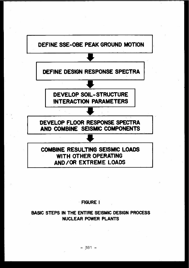
DEFINE SSE-OBE PEAK GROUND MOTION
a
DEFINE DESIGN RESPONSE SPECTR A
DEVELOP SOIL-STRUCTUREINTERACTION. PARAMETERS
DEVELOP FLOOR RESPONSE SPECTR AAND COMBINE SEISMIC COMPONENTS
COMBINE RESULTING SEISMIC LOAD SWITH OTHER OPERATING
AND/OR EXTREME LOADS
FIGURE I
BASIC STEPS IN THE ENTIRE SEISMIC DESIGN PROCES SNUCLEAR POWER PLANTS
1 .0 INTRODUCTION
The seismic design of nuclear power plants involves anumber of steps, from the definition of a design basis seismi cground motion, consideration of soil-structure interactio neffects, development of floor response spectra,- etc ., to thefinal stress analysis and design of the various components .The decisions on any one of these steps cannot be considere dindependently and/or without keeping in mind the overal lseismic design process . However, the Authors find thatlicensing of seismic design criteria is often undertaken i nseparate stages, sometimes with different groups .
Our experience indicates that almost all light wate rnuclear plants in the Western World under construction, i nlicensing or planning stage, follow the general guideline sfor seismic design as set forth by the United States Nuclea rRegulatory Commission (USNRC) or its local equivalent . Asillustrated below, this implies that each of the seismi cdesign steps in the entire design process usually involves areasonable amount of conservatism . The paper indicates tha tthe conservatism associated with each step should only b ereasonable, since its compounding, like compounding o finterest, may lead to undesirable levels of conservatism ,and to an uneconomic or impractical end product .
It is emphasized that the purpose of this paper is no tto suggest that the presently instituted conservatism b ediscarded . In fact, the paper only qualifies the conservatismassociated with present design practice, but no attempt ha sbeen made to provide the more complex quantification of thi sconservatism and its effect on the overall performanc eof the plant . Further, the Authors' experience in the fiel dindicates that the State-of-the-Art needs to advance in wel lthought out continuous increments rather than undertake th edrastic move of altering the overall philosophy presentl yused in nuclear power plant design . Finally, considering thesignificant environmental, social, economic and politica limpacts of nuclear power plants, the assurance of their safet yis necessary . However, the paper emphasizes that the curren tseismic design process is reasonably conservative and th eAuthors discourage the desire to implement an "upper bound"input at any of the design steps .
-
2 .0 SEISMIC DESIGN_ PROCESS - CONSERVATISM ASSESSMEN T
The following subparagraphs present the basic step sinvolved in the entire seismic design process (Fig 1) and poin tout areas where reasonable conservatism is believed to exist .
2 .1 Earthquake Input Motio nThe basic piece of input motion is the Safe Shutdow n
Earthquake (SSE) (1), i .e . that earthquake which is basedupon an evaluation of the maximum earthquake potentia lconsidering the regional and local geology and seismolog y
- 382 -
and specific characteristics of local subsurface material ,and which produces the maximum vibratory ground motion fo rwhich vital structures, systems and components are designedto remain functional .
Present State-of-the-Art predicates the use of adeterministic approach to the establishment of the SSE (1,2 )with emphasis placed on geology, tectonics, earthquak emechanisms and past seismicity . The Authors' experienc eindicates that every substep involved in this step of th edesign process (establishment of tectonic provinces, mappin gof major faults, definition of Intensity/Magnitude fo rhistorical events, regional attenuation characteristics ,etc .) is evaluated with a reasonable degree of conservatism .This is inherent to the fact that seismology is still a ninexact science . However, it is noted that the compoundin gof conservatism may already commence at this early stage .
After the SSE Intensity or Magnitude is determined, th eSSE zero period acceleration is obtained using Intensity-acceleration or Magnitude-distance-acceleration relationships .Several relationships are available in present literatur e(3,4,5,6,7), but the most conservative one is usually adopted .Earthquake records show that, for a given Intensity, groundmotion is lower as the distance from the epicenter increases(3) ; this effect, however, is usually ignored . Further, a talluvial or soft sites, amplification of rock motions may b econservatively postulated to occur using a one-dimensiona lshear wave propagation model (8,9) . However, such amplifi -cation is not prevalent in nature, partly due to thecontribution of surface waves to ground motion (10,11) .Finally, our experience indicates that the ultimate SS Evalue is often rounded up by the Applicant in an effort t oavoid licensing delays .
The second basic input motion, the Operating Basi sEarthquake (OBE) is ddfined (1) as that earthquake which ,considering the regional and local geology and seismology ,and specific characteristics of local subsurface material ,could reasonably be expected to affect the plant site durin gthe operating life of the plant . Present design practic enormally uses a deterministic OBE value equal to one-hal fthe SSE value . In our opinion, probabilistic evaluation sare more meaningful for an OBE event, whose recurrenc eperiod compares with the life of the plant and is, therefore ,considerably smaller than that associated with an SS Eevent (2) . These studies, in fact, tend to show that the 0 . 5SSE value might be too conservative . Also, structure an dequipment response studies (12) show that, because of th enature of the load cases considered in present practic e(combination of OBE with design accidents), and the lowe rstructural damping and allowable stresses associated wit hOBE design, the OBE, rather than the SSE, often control sseismic design . Because the SSE is intended to represen tthe ultimate resistance capacity of the plant, a nuxber o fProfessionals suggest the use of an OBE equivalent to orsmaller than one-third of the SSE .
- 383 -
2 .2 Design Response Spectr aCurrently used response spectra have been developed b y
the USNRC (13,14) from statistical (mean plus one standar ddeviation) analysis of a number of earthquake records .These include time histories recorded at soil and rock site sand for several earthquake Magnitudes and/or epicentra ldistances . The resulting normalized response spectra ,therefore, cover a wide range of conditions and ar econsidered at least conservative enough for any one site .For instance, recent studies for hard sites show that th esuggested USNRC spectra are too conservative in the vertica ldirection (15) . This is further confirmed by independen tstudies (16) which show that, even at soil sites, the presen tpractice of assuming vertical spectra equal to horizonta lfor frequencies above 3 .5 Hertz is not appropriate .
2 .3 Soil-Structure Interaction Effect sThe modification of structural seismic motions throug h
soil-structure interaction effects are routinely analyze dusing the lumped parameter approach (17,18,19) . Someparticularly unusual sites may require the support of finit eelement evaluations (19) . As the structure vibrates, par tof its kinetic energy is transmitted away into the soil i nthe form of elastic waves and this loss of energy is repre-sented in the analytical models by radiation damping . Thepeak structural response is usually reduced with increasin gradiation damping, especially at soft sites where soil -structure interaction may control structural response (20) .However, if a lumped parameter approach is implemented, eve nthough the estimated radiation damping for a typical nuclea rstructure in the Power Block area may be estimated to be 3 0to 80 per cent in sliding and vertical modes, respectively ,the actual value used in design is generally limited to amuch smaller value, resulting in a conservative structura lresponse . It is noted that the more delicate, expensive an dtime-consuming finite element analyses automatically incor -porate energy radiation, if performed properly . This ,incidentally, coupled to the small foundation damping value sused in the lumped parameter approach, explains most of th eapparent disagreements between the two methods documented i nthe literature (21) .
Further, present soil-structure interaction analyse simply that in-phase soil motion occurs at all point ssupporting the foundation . The model would be appropriateif all the surface motion was due to body waves travellin gfrom base rock . However, there is evidence that the surfac ewaves may be contributing significantly to the ground motio n(10,11) . In this case, surface wave ground motions wit hwavelengths comparable to the foundation size will tend tocancel out over a large foundation mat . Because free-fieldpeak accelerations are generally related to high frequenc ycomponents, say above 10 Hertz, the large reactor foundation swill experience significantly less intense motions than thefree field section . This effect is neglected in presen tState-of-the-Art design practice .
- 384 -
2 .4 Floor Response SpectraTraditionally, the design ground response spectra is
used to obtain the floor response spectra to check structural /equipment response . Although a number of methods ar eavailable for such an analysis (22,23,24), present practic egenerally calls for the use of an Artificial Time History(25,26), which envelops the design response spectra by abou t5 to 15 per cent on an average, with localized peaks as muc has 50 per cent higher . Additionally, structural and equipmentdamping factors suggested by the USNRC (27) may be lowe rthan those which are considered to be applicable (28) .Also, the response spectra is computed for a linear orelastic system whereas the maximum response of the structur emay be less, due to non-elastic behavior . Indeed, a slightamount of inelastic action will reduce the acceleratio nresponse spectra by significant amounts (29) . Further, theoverall process generally does not consider the feedbac kfrom the equipment into the structure ; which would reducethe equipment response (24) . Finally, comprehensive para -metric studies show that the arbitrary "broadening" of pea kresponse frequency generally used in design may be to oconservative (30) .
2 .5 Combination of Seismic ComponentsSeismic design of various structural components make s
several conservative assumptions . The seismic components inall the three directions, namely two horizontal and on evertical, are generally applied simultaneously (31) . Theratio between the two horizontal and vertical zero perio dpeak accelerations is commonly taken as 1 to 1 to 1 (14) ,whereas earthquake records indicate that the motion in ahorizontal direction perpendicular to the direction of th emaximum peak acceleration is usually smaller and that th epeak vertical acceleration may be near one-half of the pea khorizontal acceleration (16) .
2 .6 Load Cases and Combination sPresent practice calls for rather elaborate an d
relatively conservative load conditions and combinations (32) .For instance, the live and dead loads used in design ar echosen higher than the expected live and dead loads . Finally ,they are combined with unusual loads, such as pipe ruptur eloads and seismic loads, even though the pipes themselve sare designed to avoid rupture during occurrence of th edesign basis seismic event . Therefore, structures may havea resistance capacity largely in excess of that required t osustain seismic loads alone, since the additional load sconsidered in design will probably not exist during occurrenc eof an earthquake . This design philosophy may, in fact, hav esome drawbacks . For instance, an undue emphasis on unlikelyseismic loads on piping systems will increase the number an dnature of the supports to the extent that the operatin gthermal loads may become a day-to-day operational problem (12) .
-385-
3 .0 SEISMIC DESIGN PROCESS - RISK ASSESSMENT
In everyday language the term risk is used to describ ethe possibility of damage to people or property . In quantita-tive or scientific language, risk is defined as expectedmean annual damage . Thus, it is a product of the expectedfrequency of a catastrophic event, and the consequence ofthe occurrence of that event. In other words, a more frequen tevent with lower damage, such as automobile accidents, couldpossibly have the same element of risk as the infrequentevents with higher damage, for instance plane crashes . Thepublic, however, is more sensitive to the latter type ofevents .
Quantitative assessments of risks for nuclear powe rplants are indeed difficult to obtain . One 2f the problemsis that very small numbers, like 1 0-4 to 10-0 , are associatedwith risks from nuclear power plants (33,34) . The resultsof an extensive study by Rasmussen (33), indicate that th eoverall risks for human fatalities, as well as propertydamage, from 100 nuclear power plants may be about three tosix orders of magnitudes below that associated with natura land man-caused non-nuclear accidents . Whereas variousgroups have questioned these numbers, it appears that theseestimates may be appropriate within one order of magnitude .This assessment was generally concurred with in a recen tsymposium (34) by several worldwide experts working i nrelated fields .
Anyway, the essential point is that overall risks fromnuclear power plants depend upon a large number of inputs ,and seismic loads are only one of them . Reducing the seismicrisks to extremely low levels will not necessarily reducethe total risks to similarly low levels . Rather, it appearsthat a significant proportion of the total risk is contributedby small mechanical/electrical failures during norma loperation (33,34) . Further, as discussed above, there i ssome evidence that overdesigning for seismic loads may pu tunusual constraints on day-to-day structural behavior ,thereby increasing the risks due to other normal loads, suc has thermal loads, and possibly increasing the total risk .
4 .0 SUMMARY AND CONCLUSIONS
The overall seismic design of a nuclear power plan tinvolves a step-by-step selection of several design parametersand methodologies . Conservatism associated with each of thes esteps should only be reasonable, since unreasonably high con-servatism ill each or some of these steps will lead tounnecessarily high levels of overall conservatism and possiblyto uneconomic design alternatives . Further, unduly conserva -tive seismic design may not reduce the overall risk, sinc etotal risk depends heavily on a number of other independen tfactors .
- 386 -
LIST OF REFERENCE S
1. United States Nuclear Regulatory Commission, "Nuclea rPower Plants - Seismic and Geologic Siting," 10 CFR 100-Federal Register, Vol . 38, No . 218, Washington, D .C . ,November 13, 1973 .
2. Shukla, D . K ., and J . F . Kissenpfennig, "Safe ShutdownEarthquake Loading : Deterministic and Probabilisti cEvaluations," Paper K 1/3, Proceedings of the ThirdSMIRT Conference, London, September, 1975 .
3. Neumann, F ., Earthquake Intensity and Related Ground Motion ,University of Washington Press, Seattle, Washington, 1974 .
4. Trifunac, M. D ., and A . G . Brady, "On the Correlation ofSeismic Intensity Scales with the Peaks of Recorded Stron gMotion," Bulletin of the Seismological Society of America ,Vol . 65, No . 1, February, 1975 .
5. Gutenberg, B ., and C . Richter, "Earthquake Magnitude ,Intensity, Energy and Acceleration," Bulletin of theSeismological Society of America, Vo . 46, 1956 .
6. Schnabel, P . B ., and H . B . Seed, "Accelerations in Roc kfor Earthquakes in the Western United States," Bulletinof the Seismological Society of America, Vol . 63, No . 2 ,1973 .
7. Donovan, N . C ., "A Statistical Evaluation of Strong MotionData," Proceedings of the Fifth World Conference o nEarthquake Engineering, Rome, 1973 .
8. Schnabel, P . B ., J . Lysmer, and H . B . Seed, "SHAKE - AComputer Program for Earthquake Response Analysis o fHorizontally Layered Sites," Report No . EERC 72-12 ,Earthquake Engineering Research Center, University o fCalifornia, December, 1972 .
9. Seed, H . B ., "The Influence of Local Soil Conditions onEarthquake Damage," Specialty Session No . 2, Soi lDynamics, 7th International Conference on Soil Mechanicsand Foundation Engineering, Mexico City, 1969 .
10. Hall, W. J ., N . M . Newmark, and B . Mohraz, "Comments o nEarthquake Transmission from Basement Rock to Surface ,Fifth World Conference on Earthquake Engineering, Rome, 1973 .
11. Trifunac, M . D ., and F . E . Udwadia, "Variations of Stron gEarthquake Ground Shaking in the Los Angeles Area, "Bulletin of the Seismological Society of America, Vol . 64 ,1974 .
12. Stevenson, J . D ., "Rational Determination of th eOperational Basis Earthquake and Its Impact on Overal lSafety and Cost of Nuclear Facilities," Paper Kl/ll ,Proceedings of the Third SMIRT Conference, London ,September, 1975 .
-387-
13. Newmark, N . M ., J . A . Blume, and K . K . Kapur, " DesignResponse Spectra for Nuclear Power Plants," Journal ofthe Power Division, ASCE, Vol . 99, No . P02, November, 1973 .
14. United States Nuclear Regulatory Commission, "DesignResponse Spectra for Seismic Design of Nuclear PowerPlants," Regulatory Guide 1 .60, October, 1973, (Revised :December, 1973) .
15. Rizzo, P . C ., D . E . Shaw, and M . D . Snyder, "SeismicDesign Spectra for Nuclear Power Plants - State-of-the -Art," ELCALAP Seminar, Berlin, September, 1975 .
16. Hall, W . J ., N . M . Newmark, and B . Mohraz, "Statistica lAnalyses of Earthquake Response Spectra," Proceedings o fthe Third SMIRT Conference, London, September, 1975 .
17. Richart, F . E ., Jr ., J . R . Hall, Jr ., and R . D . Woods ,Vibrations of Soils and . Foundations, Prentice-Hall, Inc . ,New Jersey, 1970 .
18. Christiano, P . P ., P .C . Rizzo, and S . J . Jarecki ,"Compliances of Layered Elastic Systems," Proceedings ofthe Institution of Civil Engineers, London, December, 1974 .
19. Hall, J . R . Jr ., J . F . Kissenpfennig, and P . C . Rizzo ,"Continuum and Finite Element Analyses for Soil-StructureInteraction Analysis of Deeply Embedded Foundations, "Third SMIRT Conference, London, September, 1975 .
20. Whitman, R . V ., "Soil Structure Interaction " in SeismicDesign for Nuclear Power Plants, edited by R .J . Hansen ,The M.I .T . Press, Cambridge, Massachusetts, 1970 .
21. Seed, H . B ., J . Lysmer, and R . Hwang, "Soil-StructureInteraction Analyses for Seismic Response," Journal of theGeotechnical Engineering Division, ASCE, Vol . 101, No . GT5 ,May, 1975 .
22. Kapur, K . K ., and L . C . Shao, " Generation of Seismic FloorResponse Spectra for Equipment Design," SpecialtyConference on Structural Design of Nuclear Facilities ,ASCE, Chicago, Illinois, December, 1973 .
23. Lazzeri, L ., Floor Response Spectra by Use of a Modifie dWhite Noise Technique," Paper K 4/2, Proceedings of theSecond SMIRT Conference, Berlin, September, 1973 .
24. Newmark, N . M ., "Earthquake Response Analysis of Reacto rStructures," Nuclear Engineering and Design, North HollandPublishing Company, 20, 1972 .
25. Stoykovich, M ., "Development and Use of SeismicInstructure Response Spectra in Nuclear Plants, Pape rK 5/4, p roceedings of the Third SMIRT Conference, London ,September, 1975 .
- 388 -

26. Shaw, D . E ., P . C . Rizzo, and D . K . Shukla, "ProposedGuidelines for Synthetic Accelerogram Generation Methods, "Paper K 1/4, Proceedings of the Third SMIRT Conference ,London, September, 1975 .
27. United States Nuclear Regulatory Commission, "Dampin gValues for Seismic Design of Nuclear Power Plants, "Regulatory Guide 1 .61, October, 1973 .
28. Newmark, N . M ., and E . Rosenbleuth, Fundamentals ofEarthquake Engineering, Prentice-Hall, Inc ., New Jersey ,1971 .
29. Newmark, N . M ., "A Response Spectrum Approach fo rInelastic Seismic Design of Nuclear Reactor Facilities, "Paper K 5/1, proceedings of the Third SMIRT Conference ,London, September, 1975 .
30. Hadjian, A . H ., and C . W . Hamilton, " Impact of Soil -Structure Interaction on the Probabilistic Frequenc yVariation of Concrete Structures," Paper K 3/8 ,Proceedings of the Third SMIRT Conference, London ,September, 1975 .
31. United States Nuclear Regulatory Commission, "Combinatio nof Modes and Spatial Components in Seismic Respons eAnalysis," Regulatory Guide 1 .92, December, 1974 .
32. United States Nuclear Regulatory Commission, "Standar dFormat and Content of Safety Analysis Reports for Nuclea rPower Plants, Section 3 .0, Design of Structures ,Components, Equipment and Systems," Revision 1, October ,1972 .
33. United States Nuclear Regulatory Commission, "Draft -Reactor Safety Study, An Assessment of Risks i nUnited States Commercial Nuclear Power Plants, "WASH-1400, August, 1974 .
34. Rasmussen, N . C ., "Methodology of Risk Assessment inNuclear Power Plants," Proceedings of Symposium onReliability AnalysisofSystems and Components of NuclearPower Plants, Berlin, June, 1975 .

. Discussions
C .G . DUFF, Canada
In Canada, as I have mentioned before, we do no tnormally design for an OBE, unless for economic reasons (e .g .for piping behind shielding which is awkward to access an drepair) . We do, however, design for a DBE (similar to the SSE )treated as an "emergency condition", as defined in section II Iof the ASME Boiler and Pressure Vessel Code for Nuclear Powe rPlant Components . This allows primary stresses to reach theyield point but disregards secondary stresses, such as therma lbending stresses in a piping system, which are not importan tto single event failures . As the DBE is applied for safetyreasons only, we feel that the approach we are taking is rea -sonable . We also examine the possibility of low-cycle fatiguefailure, which does examine secondary stresses caused by th eearthquakes .
I would like to hear opinions regarding the elimi-nation of an OBE and designing only for a DBE, where the desig nlimits for the DBE are more stringent than generally applie dfor the SSE (in the latter case "faulted conditions" normall yapply where considerable plasticity is permitted) . It is sug-gested, that design for a DBE only, to emergency limits, pro -vides an adequate safety margin for the nuclear plant withou talso having to design for a lower-level OBE treated as a"normal" load, especially where in many locations a real OB Ewould probably pass unnoticed .
J .F . KISSENPFENNIG, United State s
Evidemment pour assurer la sûreté immédiate d el'installation, il suffit de la dimensionner pour résiste rà un DBE ou SSE ; mais si un séisme survient, il convien tavant de poursuivre l'exploitation de la centrale, de s'assu-rer que tous les composants ont bien supporté ce séisme, don cd'effectuer les calculs correspondants a un OBE .
D . COSTES, Franc e
Dans un pays peu sismique comme la Frame, un ORFcorrespondant à une probabilité de l'ordre de 10- par andevrait en général être fixé à un niveau très bas, n'inter-venant pratiquement pas sur la construction . Au contraire, unSSE relié par exemple à la possibilité d'un séisme intervenan tjuste sous le contrôle pourrait conduire à des précaution simportantes . L'écart entre l'OBE et le SSE devrait donc êtr eimportant dans de tels pays .

G.KLEIN, F .R . of Germany
I guess the question of the importance of SSE andOBE for the design can only be answered in connection withthe allowable stress, strain and damping as well as with th ecombination of load cases . Ïn Germany, for example, we haveoften the case that because of the mentioned reasons the OBEcontrols the design .
J .F . KISSENPFENNIG, United State s
Je suis d'accord avec M . Klein, il se peut qu'o nait à concevoir et dimensionner l'installation en fonction del'OBE. L'AIEA ne faisait pas référence à un OBE par le pass éet p crois comprendre qu'une sorte d'OBE est désormais envi-sage dans les recommandations futures . Certaines personne spensent qu'il se pourrait qu'il faille considérer 1'OBE comm eplus important que le SSE . L'OBE commande le dimensionnementlorsque ce séisme doit survenir fréquemment .
En pratique, il semble que l'installation doit êtr edimensionnée pour résister élastiquement à l'OBE tandis qu'ell edoit être dimensionnée pour résister sans ruine au SSE ; lejeu des facteurs existant entre la limite élastique et lalimite de rupture des matériaux et entre l'OBE et le SSE faitque toutes choses étant égales par ailleurs, il se, peut for tbien que ce soit l'OBE qui commande le dimensionnement .
Finalement je pense que le niveau de dimensionnementretenu vis-à-vis de 1'OBE résulte d'une analyse coût-bénéfic eque la compagnie d'électricité doit faire : ou bien ell es'assure une exploitation sans encombre en dimensionnant lar-gement, ou bien elle dimensionne au plus juste en prenant lerisque de se voir imposer une inspection complète de l'instal-lation si elle a subi un séisme plus important que l'OBE, cequi peut lui coûter une année d'exploitation de l'installation .
P .A . CORKERTON, United Kingdom
The question of the relationship between OBE andSSE has been studied in detail by the CEGB but we have no tyet come to a firm decision to specify an OBE . There is asafety argument for specifying an OBE but we do not believ ethat this should be a fixed relationship, such as a facto rof 2 which is used in the USA, for all countries or evendifferent districts within a single country . As I have said ,we have not yet come to a firm decision to specify an OBEbut if we did decide that this was the correct thing to d othen the OBE would possibly be 1/5 to 1/10 of the SSE .
[6 .2 ]
,EARTHQUAKE SAFETY OF NUCLEAR POWER PLANTS - AN INTERPRETIVE REVIEW O F
CURRENT DESIGN PRACTICE AND THE RELATED REGULATORY SYSTEM IN WEST GERMAN Y
by
Michael BORK
KERNTECHNISCHER AUSSCHUSS (KTA)-Geschaftsstelle beim Institut für Reaktor-sicherheit der TOV e . V .D 5000 Kbin 1, Glockengasse 2, Federal Republic of German y
Abstrac t
The preliminary results of the development of regulations for the seismi cdesign of nuclear power plants are discussed in respect to the intende dsix regulatory parts . While Part 1 : 'Basic principles' was issued fo rpublic comment in January 1975 and finally approved by the Nuclear Safet yStandard Commission (KTA, Kerntechnischer Ausschuss) in June 1975, th eother parts are still under development . Part 5 : ' Seismic instrumentation 'is nearing completion as a draft .
Special considerations are given to the presentation and discussion of som eof our design requirements in comparison with those defined in othercountries . Differences between the requirements of design regulations i nthese countries are primarily based upon the prevailing differences i nseismic conditions .
EARTHQUAKE SAFETY OF NUCLEAR POWER PLANTS ,
AN INTERPRETIVE REVIEW OF CURRENT DESIGN PRACTIC E
AND THE RELATED REGULATORY SYSTEM IN WEST GERMAN Y
by .
M . Bork
Geschâftsstelle des Kerntechnischen Ausschusse sbeim Institut für Reaktorsicherheit der TOV e .V . ,
Glockengasse 2, D-5000 Kdln ,Federal Republic of Germany
Preliminary results of the development of the standard KTA 220 1for the seismic design of nuclear power plants are discussed in relatio nto the intended six standard's parts :
Part 1 :
Basic principle sPart 2 :
Characteristic data on seismic inpu tPart 3 :
Dimensioning of structuresPart 4 :
Dimensioning of machinery and electrica lequipment ; functional proof
Part 5 :
Seismic instrumentationPart 6 :
Plant operation subsequent to an earthquak e
While Part 1 was issued for public comment in January 1975 an dfinally approved by the German Nuclear Standards Commission (Kern-technischer Ausschuss - KTA -)in June 1975, the other parts are stil lunder development . Part 5 is nearing completion as a draft .
Special considerations are given to the presentation and dis-cussion of some of our design requirements in comparison with thos edefined in other countries . Differences between the design requirements .are primarily based upon the prevailing differences in seismic conditions .
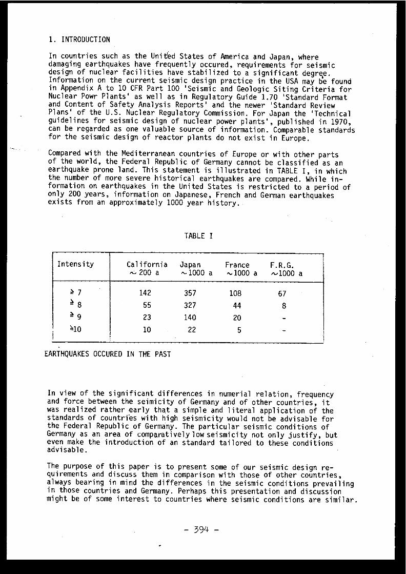
1 . INTRODUCTION
In countries such as the United States of America and Japan, wher edamaging earthquakes have frequently occured, requirements for seismi cdesign of nuclear facilities have stabilized to a significant degree .Information on the current seismic design practice in the USA may be foun din Appendix A to 10 CFR Part 100 'Seismic and Geologic Siting Criteria fo rNuclear Powr Plants' as well as in Regulatory Guide 1 .70 'Standard Forma tand Content of Safety Analysis Reports' and the newer 'Standard Revie wPlans' of the U .S . Nuclear Regulatory Commission . For Japan the 'Technica lguidelines for seismic design of nuclear power plants', published in 1970 ,can be regarded as one valuable source of information . Comparable standard sfor the seismic design of reactor plants do not exist in Europe .
Compared with the Mediterranean countries of Europe or with other part sof the world, the Federal Republic of Germany cannot be classified as a nearthquake prone land . This statement is illustrated in TABLE I, in whichthe number of more severe historical earthquakes are compared . While in-formation on earthquakes in the United States is restricted to a period o fonly 200 years, information on Japanese, French and German earthquake sexists from an approximately 1000 year history .
TABLE I
Intensity California Japan France F .R .G.^- 200 a -1000 a ti 1000 a ti 1000 a
7 142 357 108 67
8 55 327 44 8
9 23 140 20 -
10 22 5 -7
1
EARTHQUAKES OCCURED IN THE PAS T
In view of the significant differences in numerial relation, frequenc yand force between the seimicity of Germany and of other countries, i twas realized rather early that a simple and literal application of th estandards of countries with high seismicity would not be advisable fo rthe Federal Republic of Germany . The particular seismic conditions o fGermany as an area of comparatively low seismicity not only justify, bu teven make the introduction of an standard tailored to these condition sadvisable .
The purpose of this paper is to present some of our seismic design re-quirements and discuss them in comparison with those of other countries ,always bearing in mind the differences in the seismic conditions prevailin gin those countries and Germany . Perhaps this presentation and discussionmight be of some interest to countries where seismic conditions are similar .
- 394 -
2 . THE WORKING ON THE STANDARD KTA 2201
In February 1973 the German Nuclear Standards Commission (Kerntechnische rAusschuss - KTA -) commissioned a working group of experts to carry out astudy on the drawing-up of "regulations for the seismic design of nuclea r
. power plants " . This study should first of all clarify to what extent th erequirements have already been fulfilled in the sense of paragraph 2 o fthe Public Proclamation of the Foundation of a Nuclear Standards Commission .According to this paragraph, the Nuclear Standards Commission has the tas kto create and promulgate nuclear safety standards in those fields where ,based upon experience, a common opinion among manufacturers/vendors ,operators of nuclear installations, atomic licensing authorities an dreviewing organizantions can be anticipated .
One result of this study has been the recommendation to deal with the sub-ject of seismic design of nuclear power plants in the following six part sof the standard KTA 2201 :
Part 1 : Basic Principle sPart 2 : Characteristic data on seismic inpu tPart 3 : Dimensioning of structure sPart 4 : Dimensioning of machinery and electrica l
equipment ; functional proofPart 5 : Seismic instrumentationPart 6 : Plant operation subsequent to an earthquake
While Part 1 was issued for public comment in January 1975 and finall yapproved by the Nuclear Standards Commission in June 1975, the othe rparts are still under developement . Part 5 is nearing completion as a draft . .
The aim of Part 1 is to provide a general survey of the objectives an dmeasures required to maintain nuclear power plant safety in the event o fan earthquake . Along with an introductory note, the explanation of th epurpose and scope, the contents of Part 1 include :
- Reference earthquakes (definition of the Design Earthquake and Safet yEarthquake )
- Determination of reference earthquakes (earthquake zones and determinatio nof seismological engineering data )
- Classification of plant components (subdivision in two categories an dseismic design requirements )
- Loads (designation of loadings and reactions, principles for loadin gcombinations )
- Analysis (range of application for dynamic analysis, simplified analysi sor experimental proofs )
- Stresses and deformations (in the case of Design Earthquake or Safet yEarthquake permissible stresses and deformations )
Seismic instrumentation (number of seismic instruments and their delivery)
- Effects of Safety Earthquake to the site (required functional perfor-mance of Class I plant components if changes in soil foundation o rthe environs and if destruction of technical facilities occur )
In addition some citations of literature and a map of earthquakes zone sare given in this standard's part . Full information on the contents ofPart 1 can be found in this paper's appendix : A translation (10/75) of thesafety standard KTA 2201, Part 1 : Basic principles .
While Part 1 only provides a general survey on the objectives of seismi cdesign, the special details will be worked out in the other parts . Forexample Part 2 deals with the intensity/acceleration/distance - correlations ,regional and site - specific response spectra, determination of representa-tive earthquake time functions and standard investigations for the purpos eof determining dynamic characteristic data for soil foundation . Part 3 and4 will clarify especially the determination of realistic damping values ,permissible stress limits for certain materials, repercussions of simpli-fications and assumptions on the dynamic analysis processes . The number ,location and characteristic of seismic instrumentation as well as the re-quirements of plant inspection after the occurence of an earthquake will b ethe special contents of Part 5 and 6 .
In the following some design requirements will be presented in more detail eand discussed in comparison with those defined in other countries .
3 . COMPARISON OF SEISMIC DESIGN REQUIREMENT S
3 .1 Seismic input data
The German standard provides the two reference earthquakes, Design Earth -quake (DE) and Safety Earthquake (SE) . If compared with the America nOperating Basis Earthquake (OBE) and Safe Shutdown Earthquake (SSE), th edifferences between these reference earthquakes can be characterized a sfollows : The German Design Earthquake (which is the less severe of thereference earthquakes) takes the central position and forms the basis fo rthe design . The purpose of the German Safety Earthquake essentially con-sists in defining the necessary additional safety margin . According tothe definitions given in the standards's Part 1, the German reference earth -quakes are determined independently from each other on the basis of th egenerally well known seismic properties at the site and a restricted are aaround the site . Consequently, no fixed ratio between the ground accelera-tions of the two reference earthquakes has been set, as it can be found i nthe seismic criteria of the USA, which determine 'at least 50 % SSE' fo rthe OBE .
In Japan the maximum probable earthquake which is to be expected at a site ,and an earthquake which is 50 %'more severe, are considered as referenc eearthquakes . These two earthquake levels are usually designated as th eMaximum Design Earthquake (MOE) and the Safety Margin Check Earthquak e(SMCE) . The relative positions of these two Japanese reference earthquake sare the same as the positions of the reference earthquakes in Germany : th eminor one is the design basis, while the more severe one defines the re-quired safety margin . The Japanese guideline provides a fixed ratio for the
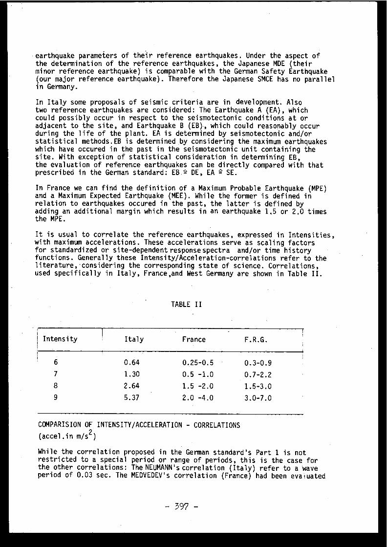
earthquake parameters of their reference earthquakes . Under the aspect ofthe determination of the reference earthquakes, the Japanese MDE (thei rminor reference earthquake) is comparable with the German Safety Earthquak e(our major reference earthquake) . Therefore the Japanese SMCE has no paralle lin Germany .
In Italy some proposals of seismic criteria are in development . Als otwo reference earthquakes are considered : The Earthquake A (EA), whichcould possibly occur in respect to the seismotectonic conditions at o radjacent to the site, and Earthquake B (EB), which could reasonably occu rduring the life of the plant . EA is determined by seismotectonic and/o rstatistical methods .EB is determined by considering the maximum earthquakeswhich have occured in the past in the seismotectonic unit containing th esite . With exception of statistical consideration in determining EB ,the evaluation of reference earthquakes can be directly compared with tha tprescribed in the German standard : EB ° DE, EA
SE .
In France we can find the definition of a Maximum Probable Earthquake (MPE )and a Maximum Expected Earthquake (MEE) . While the former is defined i nrelation to earthquakes occured in the past, the latter is defined b yadding an additional margin which results in an earthquake 1 .5 or 2 .0 timesthe MPE .
It is usual to correlate the reference earthquakes, expressed in Intensities ,with maximum accelerations . These accelerations serve as scaling factor sfor standardized or site-dependent response spectra and/or time histor yfunctions . Generally these Intensity/Acceleration-correlations refer to th eliterature,•considering the corresponding state of science . Correlations ,used specifically in Italy, France,and West Germany are shown in Table II .
TABLE I I
Intensityi
7
8
9
Italy France F .R .G .
0 .64 0 .25-0 .5 0 .3-0 . 9
1 .30 0 .5
-1 .0 0 .7-2 . 2
2 .64 1,5 -2 .0 1 .5-3 . 0
5 .37 2 .0 -4 .0 3 .0-7 .0
COMPARISION OF INTENSITY/ACCELERATION - CORRELATION S
(accel .in m/s 2 )
While the correlation proposed in the German standard's Part 1 is no trestricted to a special period or range of periods, this is the case fo rthe other correlations : The NEUMANN's correlation (Italy) refer to a wav eperiod of 0 .03 sec . The MEDVEDEV's correlation (France) had been evaluate d
- 397 -
for wave periods in the range of 0 .1 till 5 .0 sec . In Germany,th ecorrelation published in the report "Nuclear Reactors and Earthquakes ,TID-7024, Aug . 1963" had been accepted and is proposed for the assessmen tof seismic phenomina if more exact relationships are not available .
In addition to the maximum acceleration a correponding vertica lacceleration by a fixed ratio is often defined . Under the seismi cconditions existing in West Germany the maximum vertical acceleratio ncan be taken as being one-half of the maximum acceleration in the hori-zontal l direction . The reason behind this is that vertical components o fsliplike earthquakes can only play an important part at fairly great dis -tances from the epicentre of earthquakes . In West Germany, however ,dangerous earth tremors only occur in a relative proximity to the centr eso that the horizontal movements predominate by far . As this applies gene -rally to nearfield earthquakes it is not necessary to assume, as in othercountries, that the vertical motion is two-thirds or equal the horizonta lcomponent . For seismotectonic reasons the assumption of one-half of th emaximum acceleration is therefore sufficient for the maximum vertica lacceleration in West Germany .
The minimum ground acceleration for areas of minor seismicity is pre -scribed by the American seismic criteria with a ground acceleration o f1 .0 m/s2 . As far as I know the same applies to Japan and France . For Italythe minimum requirement for seismic input is 1 .8 m/s , with exception o fsome smaller regions and Sardinia . The cgrresponding value in the firs tpart of the standard KTA 2201 is 0 .5 m/s' . This acceleration correspond sto an Intensity 6, which does not represent a hazard to even conventiona lbuildings ; therefore the seismic design is essentially restricted t oinner plant components . According to the general map of earthquakeSzone sin Part 1 of the standard these minimum requirement applies to almost th ewhole northern area of the Federal Republic of Germany, more precisely said ,north from the German Central Range of Mountains, characterized as Earth -quake Zone O .
Time history and spectral functions of ground motion must be evaluate dfor the required dynamic analysis of plant components . In the Federa lRepublic of Germany the ground motion response spectra are usually de -rived by seismological institutes on the basis of foreign strong-motio nregistrations . Before the U .S . standard spectrum was published in Regu-latory Guide 1 .60 the response spectra have been specified by regardin gthe registrations of earthquakes in California with Richter magnitude scomparable with the expected severest earthquakes in our country . Thenewer requirements for the ground motion response spectra refer directl yto the standard spectrum of the Regulatory Guide neglecting the specia lseismotectonic conditions in Germany, where only magnitudes in the middl eof the Richter scale are to be expected . Further work still must be don eon this specific problem, which also will be subject of standard's Part 2 .
3.2 Design of structures and equipment
For the design of structures and equipment in Part 1 of the standar dKTA 2201 only basic requirements are given, aimed at . providing the frame -work for the drawing-up of the detailed technical requirements in th eParts 3 and 4 . As these parts still are in preparation as preliminary re -ports only a brief summary on some aspects,the discussions are concen -
- 398 -
trated on,is given in the following .
(1) Should the damping values of Regulatory Guide 1 .61 be introduced in th eanalysis of dynamic stresses acting on the plant components,but withou tregarding all the specific justifications prescribed in this Guide o rconsidering material differences,if additional design requirements ar eprovided? For reinforced concrete,forinstance,such an additional requiremen tmight' be admissable limits for the reinforcement to prevent brittl efailures . In addition - to that the calculated deformations of structura lmembers could be multiplied by a safety factor to consider the simplifie ddamping assumption in order to prove that these deformations will no tadversely affect the functional performance of Class I internals .
(2) Should the restrictions in using the lumped mass spring approches fo rsoil-structure interaction as listed in the Standard Review Plan, Sectio n
3 .7 .2, be regarded completely or only in a specific manner, consideringthe different seismotectonic situation in Germany ?
(3) Should the safety factors usually implemented for plant component sworking conditions be reduced for the dimensioning against the Desig nEarthquake ?
(4) Should the combination of the earthquake loads and the design acciden tloads (MCA) be regarded under the aspect that an earthquake might trigge rthe MCA or should be given credit to the fact, that all equipment must b eproperly designed to withstand such an earthquake ?
(5) Should the anticipated occurrence of two Design Earthquakes followe dby the one Safety Earthquake be taken as the basis for providing earth -quake safety of electrical equipment by experimental proofs in all th ecases where no precise estimation can be given by the seismologists ?In relation to that, the IEE-Standard 344-1975 propose the consideratio nof five Operating Basis Earthquakes .
(6) Should a two dimensional Diagramm be used as the first step to mak ethe decision whether a power plant site has a liquefaction potential o rnot? Only then, when the cross-point lies above a specific limit line, soi lliquefaction will be possible and experimental proofs have to be performed .
3 .3 Seismic Instrumentatio n
In Part 1 no precise requirements for number, installation and characte-ristic of seismic instruments can be found . The special standard's Part 5will deal specifically with earthquake instrumentation . As far as I know ,with exception of the USA, there can be found no detailed requirements fo rthis aspect . Some points out of the preliminary state of our discussionshould be presented and discussed in the following : That no seismic instru-ment has to be incorporated in the reactor safety system can be regarde das decisioned . If the plant should be shut down, when the instrumentationshows that the peak acceleration has exceeced the acceleration level of th eDesign Earthquake still must be discussed in view of the seismic desig nagainst the repeated occurrence of this earthquake and the Safety Earth -quake . The clarification of these aspects will be the subject of Part 6 . Weknow that this requirement stands for the USA in respect to the OBE and for Italy ,when the EB has been exceeded . A summary of our preliminary result o n
- 399 -
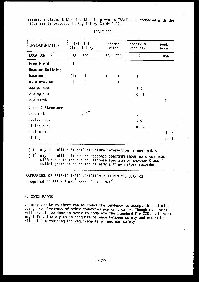
seismic instrumentation location is given in TABLE III, compared with th erequirements proposed in Regulatory Guide 1 .12 .
TABLE II I
1,INSTRUMENTATION triaxial
seismi ctime-history
switchspectrumrecorder
pea kaccel .
LOCATION USA - FRG
USA - FRG ' USA USA
Free Field 1
(1 )
1
1
1
( 1 ) x
1 1
1
1
1 o r
or 1
1
1 or
or 1
1
1 or
or 1
Reactor Buildin g
basemen t
at elevation
equip .
sup .
piping sup .
equipmen t
Class I Structur e
basement
equip .
sup .
piping sup .
equipmen t
piping
( )
may be omitted if soil-structure interaction is negligibl e
( ) x may be omitted if ground response spectrum shows no significan tdifference to the ground response spectrum of another Class Ibuilding/structure having already a time-history recorder .
COMPARISON OF SEISMIC INSTRUMENTATION REQUIREMENTS USA/FRG
(required if SSE
3 m/s 2 resp . SE
1 m/s2 )
4 . CONCLUSIONS
In many countries there can be found the tendency to accept the seismi cdesign requirements of other countries non critically . Though much workwill have to be done in order to complete the standard KTA 2201 this wor kmight find the way to an adaquate balance between safety and economic swithout compromising the requirements of nuclear safety .
i
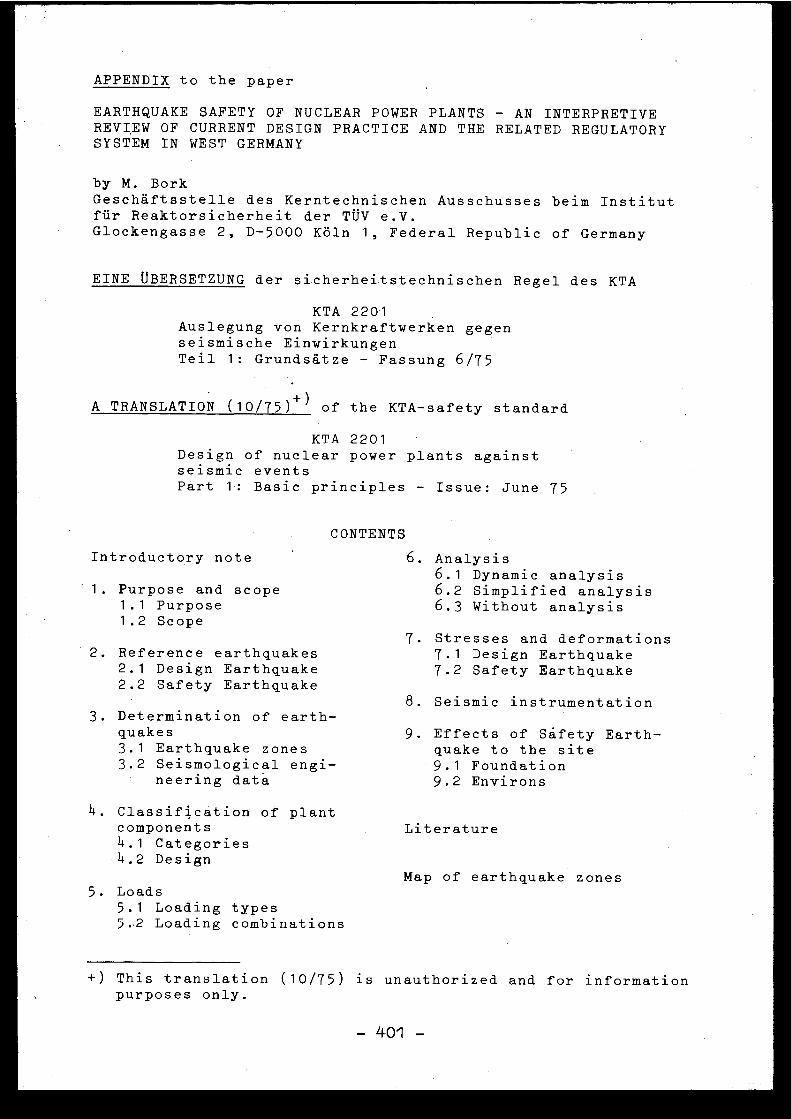
APPENDIX to the pape r
EARTHQUAKE SAFETY 'OF NUCLEAR POWER PLANTS - AN INTERPRETIV EREVIEW OF CURRENT DESIGN PRACTICE AND THE RELATED REGULATOR YSYSTEM IN WEST GERMAN Y
by M . BorkGeschâftsstelle des Kerntechnischen Ausschusses beim Institu tfür Reaktorsicherheit der TUV e .V .Glockengasse 2, D-5000 Kdln 1, Federal Republic of German y
EINE ÜBERSETZUNG der sicherheitstechnischen Regel des KT A
KTA 220 1Auslegung von Kernkraftwerken gege nseismische Einwirkunge nTeil 1 : Grundsâtze - Fassung 6/7 5
A TRANSLATION (10/75) +) of the KTA-safety standar d
KTA 220 1Design of nuclear power plants agains tseismic event sPart 1 : Basic principles - Issue : June 7 5
CONTENT S
Introductory note 6 . Analysi s6 .1
Dynamic analysi s1 . Purpose and scop e
1 .1
Purpos e1 .2
Scope
6 .2
Simplified analysi s6 .3 Without
analysi s
7 . Stresses and deformation s2 . Reference earthquake s
2 .1
Design Earthquak e2 .2 Safety Earthquake
7 .1
Design Earthquak e7 .2 Safety Earthquak e
8 . Seismic instrumentatio n3 . Determination of earth -
quake s3 .1
Earthquake zone s3 .2 Seismological engi -
9 . Effects of Sâ.fety Earth -quake to the sit e9 .1
Foundationneering dat a
4. Classification of plantcomponent s4 .1 Categorie s4 .2 Design
Map of earthquake zone s5. Load s
5 .1 Loading type s5 ..2 Loading combination s
+) This translation (10/75) is unauthorized and for informatio npurposes only .
9 .2 Environ s
Literatur e
-401 -

INTRODUCTORY NOTE
This Part 1 deals with the basic principles underlying th eseismic design of nuclear power plants . The additional part sof the standard are :
Part 2 :
Characteristic data on seismic input (under develop -ment )
Part 3 :
Dimensioning of structures (under development )Part 4 :
Dimensioning of machinery and electrica lequipment ; functional proof (under development )
Part 5 :
Seismic instrumentation (under development )Part 6 :
Plant operation subsequent to an earthquak e(presently postponed )
1. PURPOSE AND SCOPE
1 .1 P u r p o s e
The purpose of this standard is the provision of the basi cprinciples according to which a nuclear power plant has to b edesigned against seismic events .
1 .2 S c o p e
This standard shall apply to the design of all stationary nuclearpower plants in the Federal Republic of Germany . In additio nthis standard should also apply analogously to the design o fall other nuclear facilities .
2. REFERENCE EARTHQUAKE S
2 . 1 D e s i g n E a r t h q u a k e
The Design Earthquake is that earthquake with the greates tIntensity l) applying to the site that, considering a fairl yrestricted area around the site (in the same seismotectoni cunit up to about 50 km from the site), has occured in the past .
2 . 2 S a f e t y E a r t h q u a k e
The Safety Earthquake is that earthquake with the greates tIntensity applying to the site that, considering a greate rarea around the site (up t'o about 200 km from the site )/ mayoccure corresponding to scientific knowledge .
1) The " Intensit y " of an earthquake is a measure of its effect son men, structures and the surface of the earth . The termintensity, asides from the numerical value on the MEDVEDEV-SPONHEUER-KARNIK Scale (MSK 1964), also includes seismologi -cal engineering data .
-402 -
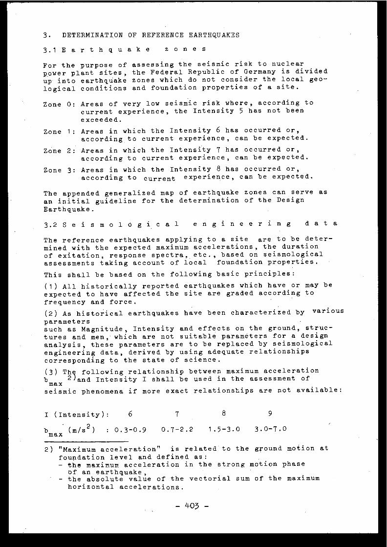
3 . DETERMINATION OF REFERENCE EARTHQUAKE S
3 . 1 E a r t h q u a k e
z o n e s
For the purpose of assessing the seismic risk to nuclea rpower plant sites, the Federal Republic of Germany is divide dup into earthquake zones which do not consider the local ge o -logical conditions and foundation properties of a site .
Zone 0 : Areas of very low seismic risk where, according t ocurrent experience, the Intensity 5 has not bee nexceeded .
Zone 1 : Areas in which the Intensity 6 has occurred or ,according to current experience, can be expected .
Zone 2 : Areas in which the Intensity 7 has occurred or ,according to current experience, can be expected .
Zone 3 : Areas in which the Intensity 8 has occurred or ,according to current experience, can be expected .
The appended generalized map of earthquake zones can serve a san initial guideline for the determination of the Desig nEarthquake .
3 . 2 S e i s m o l o g i c a l
e n g i n e e r i n g
d a t a
The reference earthquakes applying to a site are to be deter -mined with the expected maximum accelerations, the duratio nof exitation, response spectra, etc ., based on seismologica lassessments taking account of local foundation properties .
This shall be based on the following basic principles :
(1) All historically reported earthquakes which have or may b eexpected to have affected the site are graded according t o
frequency and force .
(2) As historical earthquakes have been characterized by variou s
parameter ssuch as Magnitude, Intensity and effects on the ground, struc -tures and men, which are not suitable parameters for a desig nanalysis, these parameters are to be replaced by seismologica lengineering data, derived by using adequate relationship scorresponding to the state of science .
(3) Th@ following relationship between maximum acceleratio n
bmax2 and Intensity I shall be used in the assessment o f
seismic phenomena if more exact relationships are not available :
I (Intensity) :
6
7
8
9
b max (m/s2)
: 0 .3-0 .9
0 .7-2 .2
1 .5-3 .0
3 .0-7 . 0
2) " Maximum acceleration " is related to the ground motion a tfoundation level and defined as :- the maximum acceleration in the strong motion phas e
of an earthquake ,- the absolute value of the vectorial sum of the maximu mhorizontal accelerations .
-403 -
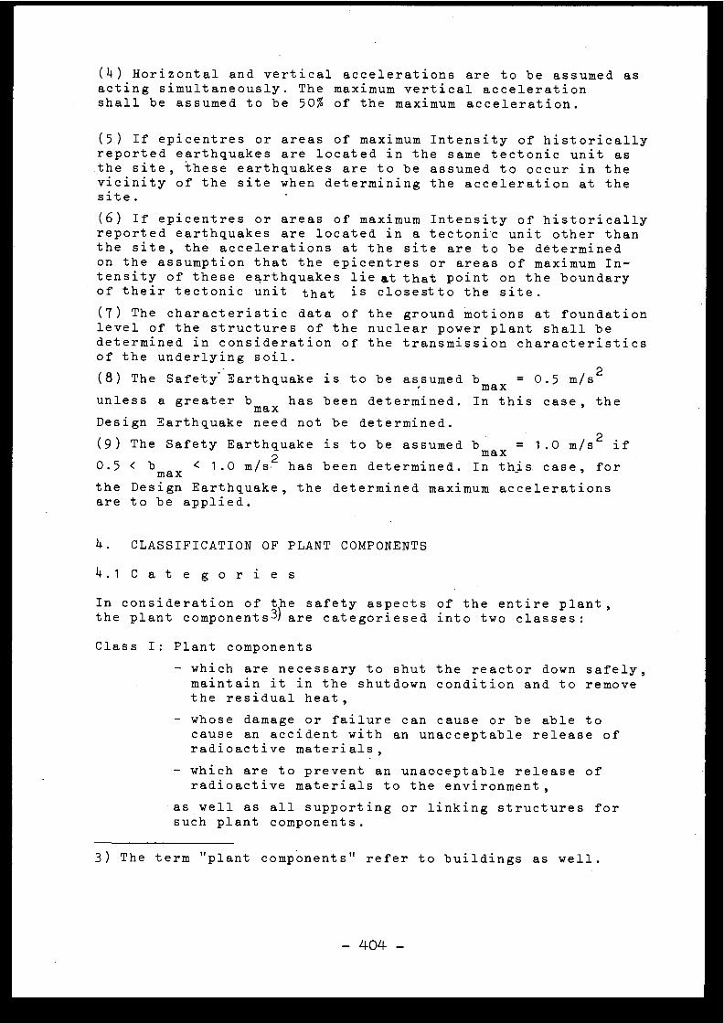
(4) Horizontal and vertical accelerations are to be assumed a sacting simultaneously . The maximum vertical acceleratio nshall be assumed to be 50% of the maximum acceleration .
(5) If epicentres or areas of maximum Intensity of historicall yreported earthquakes are located in the same tectonic unit a sthe site, these earthquakes are to be assumed to occur in th evicinity of the site when determining the acceleration at th esite .
(6) If epicentres or areas of maximum Intensity of historicall yreported earthquakes are located in a tectonic unit other tha nthe site, the accelerations at the site are to be determine don the assumption that the epicentres or areas of maximum In -tensity of these earthquakes lie at that point on the boundar yof their tectonic unit that is closestto the site .
(7) The characteristic data of the ground motions at foundatio nlevel of the structures of the nuclear power plant shall b edetermined in consideration of the transmission characteristic sof the underlying soil .
(8) The Safety Earthquake is to be assumedbmax
0 .5m/s 2
unless a greaterbmax
has been determined . In this case, th e
Design Earthquake need not be determined .
(9) The Safety Earthquake is to be assumed bmax = 1
.0 m/s 2 i f
0 .5 < bmax < 1 .0 m/s 2 has been determined . In this case, fo r
the Design Earthquake, the determined maximum acceleration sare to be applied .
4 . CLASSIFICATION OF PLANT COMPONENT S
4 . 1 C a t e g o r i e s
In consideration of the safety aspects of the entire plant ,the plant components 3) are categoriesed into two classes :
Class I : Plant component s
- which are necessary to shut the reactor down safely ,maintain it in the shutdown condition and to remov ethe residual heat ,
- whose damage or failure can cause or be able t ocause an accident with an unacceptable release o fradioactive materials ,
- which are to prevent an unacceptable release o fradioactive materials to the environment ,
as well as all supporting or linking structures fo rsuch plant components .
3) The term " plant components " refer to buildings as well .
- 404 -
Class II : All other plant components of the nuclear power plant .
1 1 .2 . D e s i g n
In compliance with this standard
all Class I plant compo -nents are to be designed that they are able to continu eoperation even after several recurrences of the Design Earth -quake and remain capable of functioning after a single occur -rence of the Safety Earthquake . A coordination of the seismi cdesign of all plant components has to be assured .
For Class II plant components, no proof according t o
this standard
is required . It is however to be proved (if .necessary, in accordance with Sec . 6) that through the effect sand damage they may be exposed to,no adversely affect of capableof functioning can be at any of the Class I plant components .
5 . LOAD S
5 . 1 L o a d i n g
t y p e s
- external loads in operating condition ,e .g . dead weight, permanent loads, live loads, operationa lloads (considering operating conditions such as scram ,refuelling), snow loads, wind loads, soil pressure, wate rpressure, slow-down and start-up forces ;
- reactions from constraint in operation condition ,e .g . forces and moments caused by temperature, creeping ,shrinkage and support displacements ;
- reactions from earthquakes, considering seperatly'th eDesign Earthquak e , and Safety Earthquake, and their resultin gconsequential effects ;
- external loads caused by damage to plant components notsafely -designed against earthquake ,e .g . pressure build-up, pressure differences, radiatio nforces, projectiles, temperature, debris loads .
5 . 2 L o a d i n g
c o m b i n a t i o n s
When combining any of the loadings and reactions listed unde r5 .1, it is to be investigated as to how far a simultaneous or sub-sequent occurrence of these loads must be considered . Transientloads counteracting the seismically induced loads are not t obe considered .
Combinations of loadings resulting from earthquakes and eart h -quake-induced accident or consequential accident loads are t o 'be taken into account .
6
ANALYSI S
6 .1 D y n a m i c
a n a l y s i s
The analysis required for seismic design are to be carrie dout by such methods (spetral-methods, time-methods) whic htake sufficient account of the characteristics of earthquake sas well as the behaviour of the soil and of the plant compo-nents .
6 .2 S i m p l i f i e d
a n a l y s i s
For nuclear power plants on sites for which the maximum Safet yEarthquake accelerations have been evaluated to less than1 .0 m/s 2 , simplified analysis may replace for the dynami canalysis .
6 .3 W i t h o u t
a n a l y s i s
If the construction as such provide for a sufficient degre eof safety or if such a degree has been proved in experimenta ltestings, an analysis can be dispensed .
7 . STRESSES AND DEFORMATION S
7 . 1 D e s i g n
E a r t h q u a k e
All Class I plant components .are to be so designed that the yare able to withstand the seismically induced loads resultin gfrom the Design Earthquake together with other loadings (se eSec . 5) within their elastic limits or the admissipJ)e corres -ponding limits according to the relevant standards 44 , in sucha way that they are able to continue operating even afte rseveral earthquakes of this type .
7 . 2 S a f e t y
E a r t h q u a k e
Class I units can be designed in such a way that the seismi cloads resulting from the Safety Earthquake together wit hother loadings (see Sec . 5) cause the stresses and/or defor-mations to exceed the elastic limits if it is proven tha tthis does not have an adverse affect on the functional per-formance of these items .
8 . SEISMIC INSTRUMENTATION
If the maximum accelerations of the Safety Earthquake wer eestablished to be
1 .0 m/ s 2 , at least two seismic instrument sare to be installed at suitable locations in the reacto r
1+) The specific standards are indicated in the Parts 3 an d
- 406 -
building - one of them on basement of the reactor building -so that it will be possible to establish whether the calculate dparameters for the Design Earthquake have been exceeded . I fa Design Earthquake parameter has been exceeded, the nuclea rpower plant must be inspected .
In addition, another seismic instrument should be installe din the 'free field' in order to provide information on the soil -structure interaction .
9 . EFFECTS OF THE SAFETY EARTHQUAKE TO THE SIT E
9 .1 F o u n d a t i o n
Changes to the - possibly improved - foundation as a resul tof earthquakes must not adversely affect the functional per-formance of Class I plant components .
9 .2 E n v i r o n s
Changes in the environs and the destruction of technica lfacilities such as can result from earthquakes (e .g . dam o rdike bursts) must not adversly affect the functional performanc eof Class I plant components .
LITERATUR E
E a r t h q u a k e
d i s t r i b u t i o n
o n
t h et e r r i t o r i u m
o f
t h e
F e d e r a l
R e -p u b l i c
o f
G e r m a n y
L1: AHORNER, L ., H . MURAWSKI und G . SCHNEIDER, " Die Verbreitun gvon schadenverursachenden Erdbeben auf dem Gebiet de rBundesrepublik Deutschland " (The distribution of damagin gearthquakes on the territorium of the Federa lRepublic of Germany), Zeitschrift für Geophysik 36 (1970 )313 ff .
L2: SPONHEUER, W ., "Untersuchung zur Seismizitâ.t von Deutsch -land "
(An investigation of seismicity in Germany),
Insti -tut für Bodendynamik und Erdbebenforschung, Jena 7 2(1962) 23 ff .
R e l a t i o n s h i p b e t w e e n n a t
i o n a la n d
i n t e r n a t i o n a l s
e
i s m i
cd e
s
i
g n r e g u l a t i o n s :
L3: BORK, M ., W . SCHWARZER, " Earthquake Safety of NuclearPower Plants,, Based on a Balanced Risk Concept " , Proceed Cng sof a Symposium on 'principles and standards of reacto rsafety', Jülich 5-9 Febr . 1973, IAEA-SSM 169/20, IAEA ,Vienna (August 1973) 181 ff .

I n t e r n a t i o n a l
a n d
n a t i o n a ls e i s m i c
d e s i g n
r e g u l a t i o n s :
L4: INTERNATIONAL ATOMIC ENERGY AGENC Y
" Earthquake Guidelines for Reactor Sitin g " , TechnicalReports Series No . 139, IAEA, Vienna (Sept . 1972 )
L5: JAPAN
" Technical Guidelines for Aseismic Design of Nuclea rPower Plants " , Japan (1970), vorgetragen in : Nucl .Engng . and Design 20 (1972) 339 ff .
L6: US A
" Seismic and Geologic Siting Criteria for Nuclear Powe rPlants " , USAEC, Appendix A, 10 CFR Part 10 0
USAEC Regulatory Guides :
- Instrumentation for Earthquake s
- Seismic Design Classificatio n
- Design Limits and Loading Combinations for Seismi cCategory I Fluid System Component s
- Design Limits and Loading Combinations for Meta lPrimary Reactor Containment System Component s
- Requirements for Assessing Ability of Material Un-derneath Nuclear Power Plant Foundations to Withstan dSafe Shutdown Earthquak e
- Design Response Spectra for Seismic Design of Nuclea rPower Plant s
- Seismic Input Motion to Uncoupled Structural Mode l
- Damping Values for Seismic Design of Nuclear Power Plant s
....L108 -
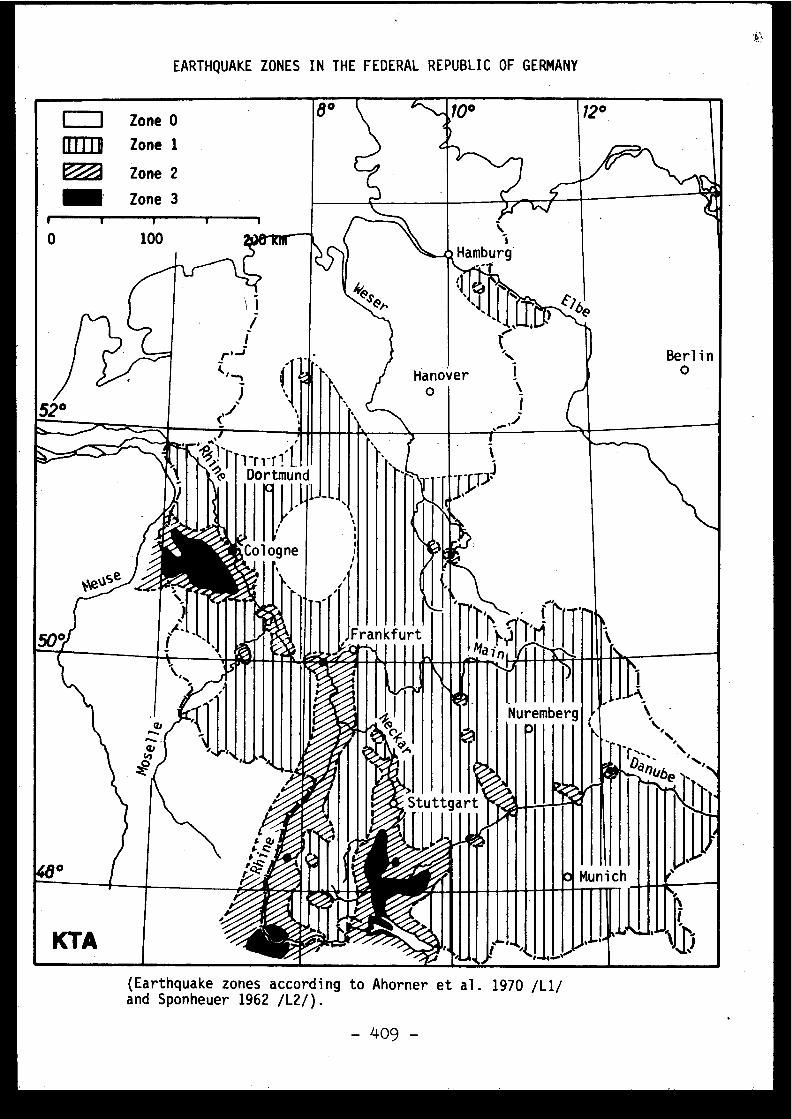
EARTHQUAKE ZONES IN THE FEDERAL REPUBLIC OF GERMAN Y
1-ri-rl ' LDortmund
c [1
[it_
Cologne
(Earthquake zones according to Ahorner et al . 1970 /L1/and Sponheuer 1962 /L2/) .
- 409 -
Discussions
J. IRVING, United Kingdom
Two levels of earthquake are specified in Mr . Bork' spaper ; what probability levels are they associated with ?
M . BORK, F .R . of Germany
For the determination of the DE, only deterministic .
J . IRVING, United Kingdom
Acceleration/intensity scaling is referred to i nthe paper for the derivation of reference ground motion data .What correlation formula has been used in the table in ar-riving at the figures given ? In our on work, reported earlierin the conference, we came to the conclusion that such correla-tions were unreliable but even so the published formula woul dgive higher figures for peak acceleration than these given inMr. Bork's paper . Which correlation formula was used in th etable of values ?
M . BORK, F .R. of Germany
For the determination of the SE, seismotectoni cresearches and the probabilities from general statistics onlyserve as additional information .
J .F . KISSENPJENNIG, United State s
Il est probable que la corrélation entre l'intensit éet l'accélération maximale d'un séisme ne s'applique pas sys -tématiquement à tous les cas et qu'il faille distinguer entr eles effets des séismes dont l'épicentre est éloigné et pou rlequel une corrélation peut s'appliquer et les effets de sséismes dont l'épicentre est proche et pour lesquels les accé -lérations semblent être plus importantes que celles indiquée spar les corrélations ; en contrepartie nous avons noté e tindiqué précédemment que l'effet d'un contenu plus importan ten haute fréquence pouvait être atténué par l'utilisation d egrands radiers .
La corrélation utilisée par Newman semble bonne s il'on se souvient que l'écart type est du même ordre de gran-deur que la valeur moyenne .
J'ajoute qu'il ne convient pas d'ajouter la valeu rd'un écart type à l'accélération pour entrer dans un spectr edu type de celui proposé par le NRC dans la mesure où ce spec-tre contient déjà une certaine marge analogue à cet écart type .
-410-

B. MOHAMMADIOUN, Franc e
Je souhaite que M. Bork supprime dans son Tableau IIla correspondance intensité-accélération pour la France .
M . BORK, F .R. of Germany
This correlation was published by the Commissio nof the European Communities as being practice in France . Ireported on the practice .
D . COSIES, Franc e
Ainsi qu'il a été exposé dans d'autres séances ,nous avons été amenés récemment à considérer des séismes pro -ches et à haute fréquence . Dans ces conditions, la corrélatio nintensité-accélération doit être tout à fait modifiée, mai snous ne voyons pas encore bien comment .
M . BORK, F .R. of Germany
As I have said in the paper the intensity/acceleratio nrelation must be regarded in the context with the respons espectra and/or time-history functions . Near site earthquake swill have a high peak acceleration but this acceleration onlycomes once or twice . If you do a correlation with high peakacceleration, after the San Fernando earthquake you must cor-relate the intensities with even higher values . In respect t othe visible non-linear effects if high intensity acceleratio noccur it might be not unconservative to take only middle value sfor our linear design calculations .
C. PLICHON, Franc e
M. Bork a fait part d'une pratique et il a euraison ; nous utilisons effectivement cette corrélation . Parcontre, quand il parle de l'état de la science, il vaudrai tmieux employer le terme de "règles de l'art", on sait eneffet qu'une structure dimensionnée avec 0,2 g, un spectr enormal et la limite élastique peut supporter des accelérationsbeaucoup plus fortes pendant un temps très court .
J .F . KISSENPFENNIG, United State s
Je suis d'accord avec M . Plichon sur le fait qu edes battements calculés avec corrélations ont résisté à desséismes d'intensité égale ou supérieure à ceux pour lesquel sils avaient été dimensionnés .
C. WEBER, Franc e
La discussion pi précède montre, s'il en était "nécessaire, que "dans l'etat actuel de la science" on peu taffirmer qu'il existe une relation claire entre intensité e taccélération maximum, surtout à proximité de l ' épicentre .
D. COSTES, Franc e
La correspondance intensité-accélération étan tentièrement fonction du contenu en fréquences et de la durée ,on veut se demander vourquoi nous continuons à utiliser l'ac-céleration comme repere de niveau, même en l'associant à unspectre de réponse . Je pense que la vitesse de sol devrai têtre un meilleur paramètre de corrélation, moins dépendan tde la fréquence .
J .F . KISSENPFENNIG, United State s
On utilise, je crois en Italie, une corrélationde Newman même si l'on pense que cela peut ne pas être bie napplicable aux séismes proches .
P .A . CORKERTON, United Kingdom
I would like to ask about the view in areas of lo wseismicity that future events can be forecast from historica levents . This is an important aspect of the specification o fseismic criteria and regulation and it is essential that wedo not finish with every country having different ways o fspecifying the SSE .
M . BORK, F .R . of Germany
To clarify the philosophy behind our practice ,perhaps it is allowed to quote a few sentences from one o fmy papers I presented two years ago at a conference :
If one can assume that the seismic conditions o fan area do not change drastically, suddenly and" unforeseeablyduring a period (plant lifetime) which is short in compariso nwith the known seismic history, then one is justified in usin gthe actual historical events as a basis for the design earth -quake(deterministically) and then derive the required safetymargin from the existing geological potential . The DE isdefined deterministically, the SE primarily considering th eseismotectonic situation of the site or the adjacent region .
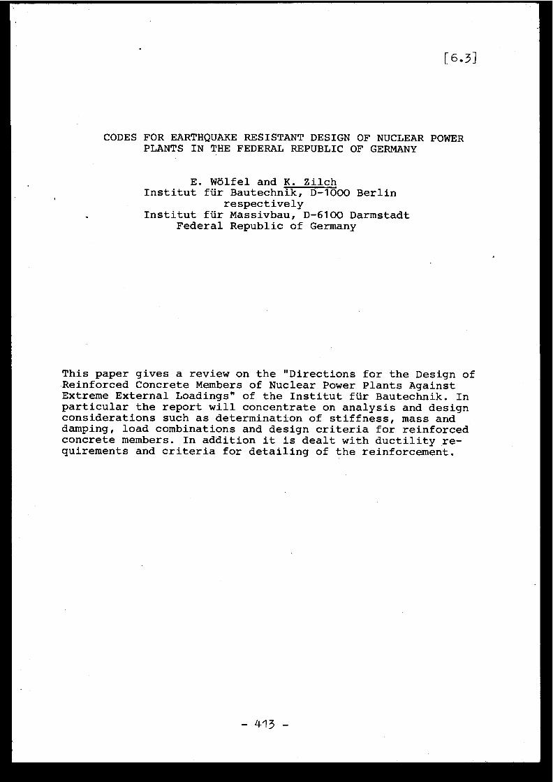
[ 6 .3 ]
CODES FOR EARTHQUAKE RESISTANT DESIGN OF NUCLEAR POWE RPLANTS IN THE FEDERAL REPUBLIC OF GERMAN Y
E . Wolfel and K . Zilc hInstitut für Bautechnik, D-1000 Berli n
respectivelyInstitut für Massivbau, D-6100 Darmstad t
Federal Republic of German y
This paper gives a review on the "Directions for the Design o fReinforced Concrete Members of Nuclear Power Plants Agains tExtreme External Loadings" of the Institut für Bautechnik . Inparticular the report will concentrate on analysis and designconsiderations such as determination of stiffness, mass an ddamping, load combinations and design criteria for reinforcedconcrete members . In addition it is dealt with ductility re-quirements and criteria for detailing of the reinforcement .
1. Introduction
In the Federal Republic of Germany it is worked on a KTA-Stan-dard on " Design of Nuclear Power Plants Against Seismic Ef-fects" . This standard is divided into 6 parts and a review o nit is given in reference [1] . Only the first part of this KTA-Standard has been finished yet . However, information for thedesign of nuclear power plants is needed today . Therefore, un -der the auspices of the Institut für Bautechnik "Direction sfor the Design of Reinforced Concrete Members of Nuclear Po-wer Plants Against Extreme External Loadings" have been pre -pared in the years 1973 and 1974 . These directions [2] ar eaimed to give uniform design criteria and to clarify ope nquestions in the design of reinforced concrete structures fo rextreme loadings . They will be used for a transition perio d
• until the respective part of the KTA-Standard has been adop-ted . However, after several meetings of the working group i tis the opinion of the anthors of this paper that the part o fthe KTA-Standard on the design of reinforced concrete member swill not differ much from the directions .
The directions cover the design of reinforced concrete member sof nuclear power plants against extreme external loadings ,that is earthquake, external explosion and aircraft crash .They are thought to supplement the German Standard DIN 104 5Dion reinforced concrete design in respect to such loadings .The directions cover only capacity requirements of the struc-ture but not other questions such as limits on deformation sor on crack width . Some of- the considerations of the commit -tee in developping the directions are discussed in a comment-ary [4] . In this report essential criteria of the direction sconcerning earthquake resistant design are to be discussed .
2. Methods of Analysi s
All methods of dynamic analysis taking into account characte-ristics .of the earthquake and of the soil as well as proper -ties of the structure are acceptable . Specially the Respons eSpectrum Method and the Time History Method are mentioned . Acertain preference is given to the Response Spectrum Method .For the design of structures the root of the sum of the squa-res is in almost any case an acceptable way of combining th emodal responses of multi-degree-of-freedom systems . This me -thod can be proved by probabilistic considerations L43 . Thatmeans, the main disadvantage of this method does not have agreat deal of meaning in the design of structures . On theother hand, by using this simple method the results dependupon the input values in a clear way and variations of para -meters may be done easily . The Time History Method gives anexact solution for a known excitation even for multi degree-of-freedom systems, however, a sufficient solution for an un -known future event is sought . This means that several time
- 414 -
histories have to be analysed or a synthetic time history ha sto be used which is a very high and in many cases unjustifiednumerical effort for the design of structures .
3. Determination of Stiffness, Mass and Damping
The static modulus of elasticity of the concrete as given inthe German Standard DIN 1045 on reinforced concrete desig n[3j may be used in the dynamic analysis . The bending stiffnes smay be determined for uncracked sections following the usua lpractice in reinforced concrete design[3) . Generally, thi sgives sufficient results . In the calculation of the mass thedead load of the structure and components, the permanent li-ve loads and a fraction of the non-permanent live loads haveto be considered . This fraction should be investigated on aprobability basis and be at least 1/2 .
The damping of a structure depends upon the actual strain le-vel (compare e .g . W) . The
directions give different per -centages of critical damping for the Design Earthquake andthe Safety Earthquake independent of the actual strain level .This simplification is . justified by requirements on the struc-tural detailing which guarantee an adequate amount of ducti -lity . The detailing requirements are discussed lateron . Forreinforced concrete members the damping may be assumed as 4percent of critical in the analysis of the Design Earthquakeand 7 percent of critical in the analysis of the SafetyEarthquake . The value of 4 percent corresponds to a strai nlevel at service loads, the value of 7 percent to a strain le -vel of yield of the reinforcement . The global assumption of th edamping avoids a step by step procedure in which damping andstrain level have to be adjusted to each other in the dynami canalysis . As the strain level changes from location to loca -tion in the structure, a strain dependent damping is also on -ly a rough approximation . An analysis with a realistic des-cription of the behavior of the material is still an unjust i-fied numerical effort for practical applications . In addition ,uncertainties in other parameters, e .g . the damping of thesoil, may have an even larger effect on the results . It i sthought that adequate structural detailing increases the sa-fety level at least as much as reducing the damping by one ortwo percent .
4. Load Combinations
Earthquake loads are to be combined with dead loads, liv eloads, and loads caused by damage or failure of components no tdesigned against earthquake . In the case of the Design Earth-quake temperature and shrinkage loads have to be considered .In addition, combinations of earthquake loads and acciden tloads caused by the earthquake must be taken into account .
-415 -
5. Strength Design of Members for the Design Earthquak e
The strength requirements for the Design Earthquake are con-sistent with the rules of the German Standard DIN 1045 131 onreinforced concrete design which gives an ultimate strent hmethod reduced by a global safety factor to service cond i-tions . However, in the case of design of members for flexur eand axial loads reduced safety factors may be used which ran -ge from 1 .4 for failure caused by the reinforcement to 1 . 7for failure caused by the concrete . This safety factors arereduced by a factor of 1 .25 compared to those of the Germa nStandard DIN 1045 [3]which is valid for usual buildings an dnormal service conditions . The German Standard DIN 1045 onreinforced concrete design contains a global factor of safe -ty, which may be splitted into three groups of partial safe -ty factors : for uncertainties in the material assumptions ,in the load assumptions, and in the general assumptions . Inthe analysis of the Design Earthquake the load safety facto rmay be omitted as it is contained in the definition of th eloading by a small probability of occurence and further un -certainties are covered by the design for the Safety Earth -quake .
For the design of members for shear and torsion the safet yfactor may not be reduced . This requirement was thought t obe necessary at the present time because of additional unce r-tainties in the behavior against cyclic shear loading .
6. Strength Design of Members for the Safety Earthquake
The strength design of members for the Safety Earthquake fo rflexure and axial load is based on the ultimate strenth me-thod . The static values for the yield strength of the rein-forcement according to the Standard DIN 1045 are taken .The re -lationship between the concrete compressive stress distribu-tion and the concrete strain is a parabola according to th eStandard DIN 1045, however, the maximum of the concrete stres sis increased to 0 .9 8
(cube strength), which is approxima-tely the cylinder strength .
In the design of shear and torsion the principal compressio nstress is limited to 0 .8 A
. However, allowable nominalshear stresses are used t owaecide on the type of analysiswhich has to be done to determine the necessary shear rein -forcement . For example, for an average concrete quality + u pto a nominal shear stress of 18 kp/c m2 analysis for the shearreinforcement is not necessary ; up to 24 kp/cm2 the concreteis considered to carry some shear and a reduction of the cal-culated shear reinforcement is possible ; and over 24 kp/cmthe shear reinforcement has to be designed for the full shearforce .
+ In this paper a concrete Bn 350 and a reinforcing stee lBSt 42/50 according to the German Standard DIN 1045 [3] areindicated as average qualities .
- .416 -
7. Details of Reinforcement
For dynamically loaded structures ductility is a major requi -rement . Avoiding brittle failure gives reserves to develo padequate damping . For reinforced concrete structures limit son the reinforcement ratio may ensure a certain ductility .Some requirements for flexural members are discussed in th efollowing .
At any section a minimum reinforcement is required at th etension side . This minimum reinforcement shall avoid brittl efailure of an under-reinforced section . The ratio dependsupon the tensile strength of the concrete and is given a smin .10 = 2 .2 • 10-5 Eb/g swith concrete modulus of elasticity Eb and the yield stres sof the reinforcement 8s according to the Standard DIN 1045 .For average concrete and reinforcement qualities minty, i sabout 0 .0018 .
On the other hand over-reinforced sections may show a brittl efailure . Therefore an upper bound for the reinforcement ha sto be established. To get ductility in flexural members th etension reinforcement must yield before the concrete com-pressive strength is reached. This condition may be used tocalculate the maximum reinforcement ratio . In the directions[2]an overall ductility factor of about 1 .3 is requested (com-pare the commentary [4] ), which results in the following for-mula for the maximum reinforcement ratio for rectangular crosssections b d
max Fe
+ f,Z l ~Max µ~
b d
v
S ( 0 .30 + 0.16 n )
with p, tension reinforcement rati oies
reinforcement ratioyield strength of the stee l
n reduced axial load n= N/bd
For average concrete and steel qualities the maximum reinfor -cement ratio difference max N°-No is about 0 .023 .
8. Conclusions
The earthquake loading is influenced by the stiffness and thedamping of the structure and the soil . The stiffness and thedamping, however, depend upon the reponse level . The deter-mination of the stiffness, mass, and damping are interrela-ted with the response and the structural detailing . Specialprovisions for ductile behavior may increase the earthquakesafety considerably and at least as much as a small decreas ein damping . Therefore, a code on earthquake resistant desig nshould have in view this fact and should give adequate inter -related provisions on the entire scope .
-417-
9 . References
0] Bork, M . : Earthquake Safety of Nuclear Power Plants, anInterpretive Review of Current Design Practice and the Re -lated Regulatory System in West-Germany . Paper presentedat the OECD - NEA Specialist Meeting on the Anti-SeismicDesign of Nuclear Installations, Paris, 1 - 3 December1975 .
[2] Richtlinien für die Bemessung von Stahlbetonbauteilen vo nKernkraftwerken für auf3ergew8hnliche auBere Belastunge n(Erdbeben, üul3ere Explosionen, Flugzeugabsturz) .Mitteilungendes Instituts für Bautechnik Berlin, 6/1974 .Revision of eôtion 7 .1 : Mitteilungen des InstitutsifürBautechnik Berlin, 1/1976 .
!
[31 DIN 1045 : Beton- und Stahlbetonbau, Bemessung und Ausfüh-rung . Ausgabe Januar 1972 .
[4] Stangenberg, F . ; Zilch, K . : Erluterungen zu den "Richtli -nien für die Bemessung von Stahlbetonbauteilen von Kern-kraftwerken für auBergewôhnliche auBere Belastungen (Erd-beben,ul3ere Explosionen, Flugzeugabsturz) " .Mitteilungen des Instituts für Bautechnik Berlin, 1/1976 .
[5] Newmark, N .M ./Rosenblueth, E . : Fundamentals of Earthquak eEngineering . Englewood Cliffs, New Jersey : Prentice-Hal l1971 .
[6] Newmark, N .M . : Earthquake Response Analysis of ReactorStructures .Nuclear Engineering and Design 20 (1972), p . 303-322 .
Discussions
J .Z . ZEMAN, Austria
If I remember correctly, Mr . Zilch has stated thatthe SRSS (Square Root of the Sum of Squares) method can b eproved by probabilistic methods . If he attaches to the wordproof the same meaning than I do, this statement is wrong .If one uses a lot of assumptions, all that can be shown i sthat the result obtained by means of the SRSS method has any -thing to do with the standard deviation of a response .
K . ZILCH, F .R. of Germany
The earthquake is a probabilistic event and thereforeprobabilistic methods must be accepted in dealing with thi sproblem. To justify combining the modal responses by the roo tof the sum of the squares one needs only assumptions which ar ecommon within the frame of random vibration theory (comparereferences) .
//

General Discussion
Discussion générale
C .G . DUFF, Canada
The question was asked how other countries wit hlimited historical seismicity obtained their SSE . Can you us ehistorical data alone, how, and if not what can you do ? W ehave a similar problem in Canada where the regions in whic hnuclear plants are being built are not close to known activ eor even capable faults, although there are clusters of earth -quake activity called earthquake "trends" .
While historical events must be used, an examinationof world seismicity as a means of compressing historical tim e(as related to a particular site) must be used, suitably ad-justed to account for local and regional geology, as well a sfor seismotectonics pertinent to the site . This is a compli-cated process but can lead to reasonable prediction s . with anupper-bound magnitude related to the strength of the rocks .The location of the focus of such a maximum-magnitude even tis the only real uncertainty, as it is completely random ,within the seismotectonic province containing the site . Thi sis where historical seismicity comes in . It is used to helpdetermine the probability of a given magnitude event occurrin gclose to the plant site, including the maximum-magnitude event .
N .N . AMBRASEYS, United Kingdom
Historical seismicity is invaluable for the assess -ment of seismic risk . Long periods of seismic activity o rquiescence are common and unless studied carefully we may hav esurprises .
As for the correlation between intensity and acce-leration mentioned earlier, this is so weak that if one ha sto play a hunch on the data one might as well play a hunc hon the results .
J .F . KISSENPFENNIG, United States
Je suis d'accord avec le Professeur Ambraseys su rle plan technique mais je pense qu'il convient de regarde rl'ensemble du processus de dimensionnement de l'installation .
M. Costes se demande si une coordination des travauxsur le problème des séismes pourrait être envisagée entre le sdifférents pays .
Nous sommes au troisième jour de notre réunion e tje vois que nous en revenons au sujet du premier jour qu'étai tla détermination du séisme à prendre en compte et de ses ca-ractéristiques ; il existe une grande incertitude dans ce domain e
- 420 -

alors qu'il semble qu'il y ait moins d'incertitude en ce qu iconcerne les techniques d'analyses .
Le Professeur Ambraseys a dit que si nous voulon saméliorer nos données et nos calculs, nous avons beaucoup d eprogrès à faire dans de nombreux domaines .
Je propose que nous en revenions aux oints indi-qués dans l'ordre du jour : la cohérence des precautions para-sismiques avec l'ensemble des précautions de sûreté nucléaire ,avec peut-être avec un certain souci de ne pas prendre desprécautions excessives ; la standardisation des précaution speut-elle être envisagée malgré la diversité des condition srencontrées dans les différents pays ; quelles sont les pers-pectives de collaboration dans le domaine réglementaire ?
D . COSrES, Franc e
Je propose qu'un voeu sur la coordination des tra-vaux soit inclus dans les conclusions - de la réunion .
J .P . ROTHE, Franc e
Je pense qu'il serait intéressant que des exemple sde travaux de sismicité exécutés dans tel ou tel pays soien tlargement diffusés accompagnés des données qui ont été utili-sées . Je pense en particulier aux cartes sismotectonique sactuellement préparées en France ou bien à la carte de cour -bes d'isoprobabilité dont M . Giuliani a parlé lundi pourl'Italie . En possession de ces documents, chacun serait mieu xen mesure de juger si ces méthodes peuvent s'appliquer dan sson propre pays .
G.KLEIN, F .R . of Germany
Regarding the last statement of Professor Ambrasey sI completely agree that the correlation intensity/acceleratio nis very poor. But which figures can we use as engineers in ou rcalculations ?
N .N. AMBRASEYS, United Kingdom
We have to work more with the seismologists and tryto solve the problem which will give us a more realistic mea -sure of the intensity
G.KLEIN, F .R. of Germany
But we cannot draw figures out of a hat !

N.N. AMBRASEYS, United Kingdom
It is a fact that seismologists begin to giv efigures .
G . KLEIN, F .R . of Germany
I am skeptic .
N.N . AMBRASEYS, United Kingdom
and talk. Seismologists and engineers should come togethe r
G. KLEIN, F .R. of Germany
Personnally,I would like to congratulate Mr . Costesin organizing this meeting . I have got a lot of informatio nfrom different countries about earthquake influences o nnuclear power stations . But for future meetings, which coul dbe of great use, the topics should be a bit narrower so tha twe could present and discuss them in detail .
D. COSTES, Franc e
Je vous remercie,M . Klein . Je reviens à la cohérenc edes précautions parasismiques avec l'ensemble des précautions .Examinant l'ensemble des maillons de la chaîne de raisonnements ,on revient au premier ; mais des incertitudes subsistent dan sd'autres .
Les deux principaux domaines d'incertitude parais -sent les suivants :
- données d'entré e
- résistance des structures dans les domaines d edétériorations partielles .
Il semble qu'un certain accord se rencontre dan sles autres domaines où l'on pourrait se concentrer .
E. COBB, United Kingdom
While this meeting has concentrated on aspects o fanti-seismic design it must be remembered that there may b erequirements to design a nuclear power station against othe rexternal hazards (e .g. aircraft crash) .
This will not allow the ideal solutions for anti -seismic design to be applied (assuming that they can be spe -cified) but will demand compromises to best meet the variou sdifferent conditions which are specified .
-422 -
G.KLEIN, F.R . of Germany
I would like to make some modifying remarks to th estatements of Mr . Costes . If we have a consensus on some pointsit is only the consensus that our knowledge about these point sis still poor . So I would recommend to bring also those point sas for example intensity/acceleration-correlation or soil -structure interaction for presentation and discussion forfuture meetings .
D . COSTES, France
Je pense qu'il faudrait étendre la question de lacorrélation intensité-accélération, puisque l'accélérationparaît systématiquement très mal corrélée avec l'intensité .Il faudrait soit définir un ensemble de paramètres physiques ,soit se limiter au meilleur, qui me semble devoir être plutôtla vitesse maximale de sol que l'accélération .
A. LOPEZ ARROYO, Spain
I would like to insist on the two points raised byProfessor Ambraseys ; the time stationarity of the seismicityand the correlation between intensity and acceleration .
With regard to the first point, Mr . Bork has saidthat seismologist believe seismicity does not change withtime in the large . I remember the "non-law"given by Richterand quoted by Lomnitz "at places where there have been n oearthquakes, there will not be any in the future ; but if oneoccurs, it is bound to occur more" . That uncertainty shoul dbe considered in both the determination made through th edeterminist and the probabilistic approach . My feeling i sthat the deterministic method is more sensitive to this . Asfor the intensity-acceleration correlation, a main difficul-ty comes from the present definition of intensity . Our seismo-logists are working on a new definition in which factors suc has duration and time-history are considered ; some are als oconsidering the possibility of giving different values fordifferent frequency ranges, thus solving, perhaps, the problem sinvolved with the interpretation of the data presented byProfessor Ambraseys .
D . COSTES, Franc e
Comme question générale à l'assemblée, j'aimerai ssavoir si la procédure de détermination des séismes de réfé-rence, décrite dans les "Regulatory Guides" des Etats-Unis ,est suivie dans les autres pays .

J .P . ROTHE, Franc e
L'application stricte des Règles américaines àl'Europe occidentale est très difficile ; les grands accident saméricains de plusieurs centaines de kilomètres de longueu rne se rencontrent pas en Europe . Le règlement américain pré -voit l'étude des accidents tectoniques autour d'un site dan sun rayon de 320 km . En Europe occidentale de telles distance sintéressent plusieurs provinces sismotectoniques .
J .F .KISSENPFENNIG, United States
Or course, Appendix A 10 Cr'E 100 proposed by th eUSNRC needs to be adapted to local conditions and countries .However, it appears that the general "philosophy" of determi-nistic criteria for SSE are accepted worldwide .
E . ROBERT, Franc e
Je formule d'abord une suggestion tendant à prévoi rau titre des travaux ultérieurs la collecte d'information ssur les séismes observés dans les différents pays et l'examendes enseignements que l'on peut en tirer pour l'élaboratio nde la réglementation et des règles constructives antisismique sen matière d'installations nucléaires .
Certains de nos collègues ont, d'autre part, marqué ,me semble-t-il, un certain pessimisme en raison des difficulte srencontrées pour l ' élaboration de normes détaillées et précise sd'application générale .
Pour tempérer ce pessimisme, je citerai le cas de sgrands barrages . Des questions importantes de sécurité s' ytrouvent posees . Il y a par année en moyenne un accident gravedans le monde . Malgré l'expérience acquise par les construc -teurs depuis une cinquantaine d'années, la Commission interna -tionale des grands barrages, qui groupe tous les intéressé sdans ce domaine, a estimé préférable, notamment pour la fixa-tion de la capacité d'évacuation des crues, de s'en tenir àdes recommandations d'ordre général à l'intention des construc -teurs, à qui il appartient pour chaque ouvrage de détermine rles précisions nécessaires .
On retrouve ici les problèmes posés par un phénomèn enaturel extrême, comme en matiere de séismes .
J'indique, enfin, que la Commission précitée vien tde publier une brochure faisant le point de la question de l aprotection parasismique des barrages (Commission international edes grands barrages, Comité des tremblements de terre, "Un erévision du calcul sismique des barrages", Bulletin 27 ,mars 1974) .
-424-
GENERAL CONCLUSIONS OF THE MEETING
D.Costes, before closing the meeting, asked whichmajor conclusions should be included in the proceedings . Thecontribution was summarised as follows :
- The principal conclusion was that current knowledgewas inadequate but it was unanimously felt that furthermeetings would be valuable, for example a similar plenarymeeting in two years time, but that there was a particularneed for more restricted meetings on specific subjects .
- The technical subject giving rise to most discussio nwas the determination of reference earthquakes and of thenumerical parameters corresponding to the chosen intensities .
- A finer description of seismic movements was neces -sary in order to assess their effect on foundations ; methodsfor calculating the interaction were already well advance dand it should be possible for them to be adapted to the phys -ical requirements .
- Calculations relative to structures and equipmentwere also limited by the lack of data about materials in thedamaged state, which were bound to be considered in any over-all probabilistic approach .
- There was overall agreement about this probabilisti capproach, although there were reservations about the diffi-culty of assessing probabilities of rare phenomena and th eproblems of public information .
CONCLUSIONS GÉNÉRALES DE LA RÉUNION
D . Costes demande avant clôture de la réunion quelle ssont les conclusions majeures à reporter sur le compte rendu .Les interventions peuvent être ainsi résumées :
- Bien qu'il soit noté que le consensus rencontr éconcerne surtout l'insuffisance de nos connaissances, onconsidère unanimement que des rencontres ultérieures serontutiles, par exemple une telle réunion plénière dans deux ans ,mais surtout des réunions plus restreintes sur des sujet sprécis .
- Le sujet technique le plus discuté demeure le choixdes séismes de référence et des paramètres numériques corres -pondants aux intensités retenues .
- Une description plus fine des mouvements sismique sest nécessaire pour apprécier leur effet sur les fondations ;les méthodes de calcul de l'interaction sont déjà bien déve-loppées et devraient pouvoir être adaptées aux nécessité sphysiques .
- Les calculs de structure et d'équipements trouven tégalement leurs limites dans le manque de données sur le sétats dégradés des matériaux, qu'il faut bien considérer dan sune approche probabiliste globale .
- Cette approche probabiliste donne lieu à un accor dde principe sur le fond, sous réserve des difficultés d'aapré -ciation des probabilités de phénomènes rares et des problemesde présentation au public .
REPORT BY THE CHAIRMAN OF THE MEETIN G
~ .
Antiseismic Precautions in Different Countries
Many of the papers presented dealt with generaltopics ; however in conjunction with the discussions tha ttook place they do enable a comparison to be made betweenthe antiseismic precautions adopted in the different countriesand the occasionally substantial problems which remain .
The best . known and most frequently used method i sthat of the United States, based upon official documents . Itmay be summarised as follows :
- Calculations are done in terms of two referenceearthquake levels, the OBE (Operating Basis Earthquake) whic his relatively probable and following which no further safet yexamination is required before the plant is put back int oservice, and the SSE (Safe Shutdown Earthquake) which is muc hless probable and for which it can be guaranteed that th eessential safety systems will function .
- The OBE and SSE levels are defined in a primaril y"deterministic" manner using a detailed procedure involvin gfixing earthquake magnitudes and their location on identifiedseismotectonic structures as close to the site as possible .In practice, the OBE is taken to be one-half the SSE .
- The local earthquake level is defined by an energydiffusion law appropriate to the region and not specifiedbeforehand .
- The spectral content of the free movement of th eground is given by an imposed response spectrum .
- Any method may be used for obtaining the respons eof the structure but a direct time-history calculation isrecommended, with a collection of actual seismograms or asynthetic seismogram, compatible with the chosen spectrumwhich should cover the actual spectrum except for a few peaks .
- The damping coefficients of the structure and thepermissible limiting states are imposed, and related to th edifferent instances of loading .
- In order to determine the movement of equipment ,the peaks of the floor spectrum are arbitrarily broadened inorder to avoid resonances linked to evaluation errors : Con-versely, the influence of equipment on the structure is notusually taken into consideration ; its effects would b eattenuating .
-427-

- Combinations of loadings are imposed ; no consider-ation is given to simultaneous SSE and the major primary rup -ture accident .
A guide has been drawn up for the equally wel lestablished Japanese procedure . The "Maximal Design. Earth-quake" corresponds to the evaluation of the most intens eearthquake experienced on the site, which seems to be particu-larly suitable in this country where earthquake focuses aredeep and the effects extensive . A "Safety Margin Check Earth-quake" is obtained by multiplying the movement of the MDE by
/a factor 1 .5, and corresponds to the SSE . The ground spectra ,which are not specified in the guide, must correspond to th emagnitude of the earthquakes and be appropriate to the site .All methods of dynamic analysis are permissible, and advic eis given for their application, as well as for ground tests ,the anti-seismic design of structures and so on . For the SMCE ,the hypothesis of simultaneous rupture of the primary circui tis disregarded .
Germany is in the process of drawing up detaile dregulations ; these resemble the American system, but consi -deration will be given to the special features of this regionof low seismicity . Precise directives are already in forc ewith regard to reinforced or prestressed concrete structure ssubjected to dynamic loading .
In France, the United States method has been appliedto power station schemes of the American type ; the difficultyhas been to reconcile the excitation levels likely in Franc e(shallow, low energy earthquakes) to the American type ofspectrum . Current practice is to maintain the principle o fchecking installations at two earthquake levels evaluated onthe basis of historical and seismotectonic observations ;however, national regulations are now being drawn up and th eentire system may well be revised according to specific seismi cfeatures of the country . The primary aim is to draw up anaccurate seismic map and specify local earthquake probabili-ties . Over the greater part of the country seismicity is verylow and it would appear that the earthquake risk can be evalu-ated only on a statistical basis considering very large regions ;however certain regions have highly specific characteristic sand the evaluation should take account of seismotectonic data .
In the United Kingdom, such developments are at anearly stage owing to the low seismicity . Since it is doubt -ful whether seismotectonic provinces can be identified, th ehypothesis of the uniform risk probability has been adopted ,leading to a simple evaluation of local risks using al lhistorical data . If a risk level of the OBE type were to b etaken into consideration, it would be at a very low level .Current work is also concerned with analytical methods, pre -ference being expressed for direct time-history method sallowing non-linear elements to be taken into account .
-428 -
In Canada, there are a number of original ideas . Inthe East, where seismicity is low, no OBE is worked out ,except for certain parts of a plant to which access is diffi-cult and repairs unlikely but for which continued performanc eis desirable in the event of an unlikely earthquake . Earthquakeprobabilities are expressed on the basis of general distribu-tion laws, calibrated from regional observations . The methodof dynamic analysis is highly simplified ; algebraic movement sare taken into consideration with the result that the respons escales can be ranked according to the chosen spectrum . Devel-opment work is continuing with regard to a real-time calcula -tion on the power variations that should be imposed on a reacto rin the event of an earthquake, having regard to the situatio nin the various parts of the plant .
The following sections review the principles dis -cussed in the main fields of interest .
2 .
Determination of the Safety Earthquake (SSE )
This question gave rise to wide ranging discussion ,with the seismologists claiming that they were unable to pro -vide rigorous quantitative evaluations in this field of earthsciences and the engineers requesting calculated values . Itwas acknowledged that meetings such as this would have tothrow light on the questions of terminology and the criteriaused in decision-making .
In the process of determining the safety earthquak eit is possible in principle to distinguish the "deterministic "approach and the "probabilistic" approach, but there are nuanceswithin each .
The deterministic approach tries directly to obtaina maximum earthquake level possible on the site . The procedurerecommended by the USNRC causes problems in regions of lowseismicity and complex geology such as France . The maximummagnitude worked out from historical and seismotectonic argu -ments is relatively low and one can therefore confine one' sattention to a fairly restricted zone, but it is not easy t odefine faults capable of activity because they do not generallycome to the surface . Historical epicentres have to be locatedwith precision, if guidance is sought for geophysical research .Intensities observed historically over restricted areas arealso difficult to define .
In the probabilistic approach, one tries to determinethe probabilities for each level of earthquake on the site .A distinction is made between the overall regional evaluationwhich assumes that the earthquakes are distributed randomlyand the differentiated evaluation made by considering theknown seismogenic structures and distributing earthquak eprobability functions over them, thus producing local riskmaps . This differentiated evaluation is possible only for a .region of relatively high seismicity in which the seismogeni cstructures can be considered as historically well demonstrated .
-429 -
An intermediate process consists in measuring an overal laverage risk and then differentiating it on the basis o fqualitative arguments of seismotectonic and seismic history .Having obtained the probabilities for various earthquake level son the site in question, the SSE is set at a level appropriat eto the safety options, introducing the margin involved in theday to day calculations .
To be able to determine the overall risk of a seriou saccident due to an earthquake, the product of the probabilitythat a given level will occur and the conditional probabilityof rupture at this level would have to be integrated over. al learthquake levels . This would involve complicated calculationsand it is possible to be content with a single verificatio nat a single earthquake level . For exmple, it can be taken thatthe overall risk does not e ceed 10-66 a year if the earthquakewith the probability of 10-, a year leads to a conditiona lrupture probability of less than 10- 2 . The probabilistic metho dis generally acknowledged as being more coherent in principle ,but stress is laid on the difficulties of assessing the proba -bilities of very rare events . The author points out for exampl ethat with regard to floods, the determination of the thousandyears or an arbitrary extrapolation based upon observation sover a shorter period, since the phenomenon is considered onlyin the valley liable to be affected . In an area of low seis-micity considered to be homogeneous, the local rareness of anearthquake is linked basically to the random dispersion o fearthquakes over the whole country, for the phenomenon may wellbe studied historically at other points . This geometric effectmakes it possible to take into consideration local probabili -ties at a level much lower than for floods . The safety earth-quake (SSE) can be evaluated either directly in terms o fphysical parameters based upon the magnitude, distance an dlocal data, or via the macroseismic intensity . The problem i sthus one of correlating this intensity with the physical para -meters of the movement .
The question of the existence in the underlying landof faults capable of activity, and the possible consequence sof higher dams being damaged by earthquakes were not deal twith .
3 .
Correlation between Intensity and the Physica lParameters of the Movement
The movement of the ground can be defined eithe ron the surface or at the bedrock by means of a time-historydescription (seismogram) or by a frequency description whic hpresents the essential data in the form of a spectrum, astatistical figure simpler to read than a seismogram . Theground spectrum is characterised by a shape and by a level ;the level may be fixed by a maximum value of the acceleration ,velocity or displacement, or by any combination of thes equantities . The maximum acceleration of the ground, measure don the seismogram, does not correspond in principle with th emaximum acceleration shown on the spectrum, because the variou sfrequency components combine to produce the overall movement .
- 430 -
In calculating the effects of earthquakes by th equasistatic method, the practice has been to describe theintensity in terms of an acceleration . In fact, it is wellknown that short-duration and non-destructive earthquakes canshow very high acceleration peaks . A priori the maximum groundvelocity would be a better parameter for correlating withintensity ; SE EBALIN has published a formula which also intro -duces the dominant period and the duration of the earthquake .
In principle the movement of a point on the groundis not sifficient for defining the intensity, because theground-foundation interaction depends upon the characteristic sof the. ground and on those of the seismic waves being propa-gated ; this interaction is fundamental in consideration o fdestructive effects . The characteristics of buildings arealso significant . In any event therefore the correlationbetween intensity and the physical parameters of the movementmay be expected to be fairly loose .
The large number of recordings now available ,obtained notably by seismographs in Europe, should now enabl ea systematic study to be made of the correlation between thedestructive effects of earthquakes and of the physical para-meters of the movement ; one could thus better interpret pas tearthquakes known to us by their destructive effects . Ofparticular interest are the readings given by interconnectedinstruments which show the effects related to the response sof foundations and buildings .
4 .
Methods of Dynamic Analysi s
The ground and structures are schematised eithe ras lumped masses or as finite elements .
The local movement of the ground is described eitherby time-dependent laws x (t), or by a spectrum which is theoutcome of a statistical treatment of an x (t) law and asmoothing process . Synthetic x (t) laws can be developedto correspond to a given spectrum, but so far it does notseem that a given law can be made to correspond to the complete ,response spectra which has been proposed with the variousvalues of damping coefficients .
To obtain the dynamic response of the plant, it i spossible :
- to determine the modal responses from the respons espectrum and combine these according to proven laws (th estraightforward quadratic combination seems too optimisti cin view of the possibility that response peaks may coincid ein these transient movements) ,
- to follow the modal responses and to sum them u pat each moment using a step-by-step time calculation wit hrecorded or synthetic x (t) functions ,
-431 -
- to calculate the overall response in a step-by-steptime calculation without embarking upon a modal breakdown ,thus making it possible to take account of any damping value ,non-linearities, and variations in characteristics due t ofatigue .
These methods differ in their probability content ,(shown in decreasing order above) and in the length of th ecalculation (for which they are in increasing order) .
A new method was described in which the law x (t )is given as a time-modulated random function, but it has no tyet been applied .
There was general agreement that the simplest method swere very satisfactory for initial studies but opinions differe das to the degree of complexity finally required . A balance mustcertainly be struck between the degree of refinement of th ecalculations and the lumped nature of the assumptions mad eregarding the movement ; comparisons between the result sobtained using various methods for a given case are therefore ,extremely interesting and should provide future guidance .
5. Behaviour of Materials and Construction s
The nuclear aspect of installations, their safetyranking and the permissible limiting situations did not giv erise to any particular discussions . It appears necessary t ofix an earthquake threshold of the "Operating Basis Earthquake "type for which it is shown that the installation suffers n odamage and if exceeded would result in the plant being re -examined . The threshold itself can be fixed very loosely ,for example by the user on an economic basis . In principle ,it is accepted that the effects of the earthquake and o faccidents induced by the earthquake may be simultaneous ,although there was no discussion of the corresponding chronol-ogy . Opinions differed as to whether the effects of the SS Eearthquake and the most serious reference accident - los sof coolant - should systematically be taken into consideration .Certain draft regulations state that the stress level due t othe earthquake should be compared with the operational stres slevels before it is decided whether accidents were triggeredby the earthquake .
Permissible limiting states in materials were deal twith from a primarily theoretical standpoint .
The behaviour of soil and foundations were similarlydealt with theoretically in discussions on the inclusion o fnon-linearities in calculations . There was also discussio non how representative were measurements on specimens .
6. Tests
See the proceedings of Session N° 5 .
-432-
7 .
Instrumentation
A great deal has been done to set up strong motio nscientific instruments in the various countries . As alreadymentioned, centralisation and use of the recordings shouldbe made more systematic and speeded up .
The problem arises of requiring the nuclear operatorsto be responsible for the scientific instruments . This require -ment could coincide with that to qualify site movements fromthe standpoint of the OBE, insofar as the additional load ona more accurate instrument is not too high. Meanwhile ther eis a scarcity of experimental data about the movements o frigid structures like nuclear power stations, and instrumen-tation arranged at a nomber of points (including undisturbedground), sensitive to medium amplitude movements, would advance .knowledge or confirm assumptions made for the plans in question .Such instrumentation systems could therefore be mandatoril yplaced on sites of relatively high seismicity .
It is also possible to conceive of using very simpl einstruments such as seismoscopes and direct-reading device sshowing maximum deformation and relative movement, in relatio nto operating safety .
s
8.
Regulations
Various countries are now in the process of drawin gup anti-seismic regulations or standards for nuclear reactors .Compared with the specifications applied in the United State sand Japan where there are regions of high seismicity, thetendency is to adapt legislation to a lower seismicity andto existing national regulatory practices .
The IAEA Guide now under preparation, the presentmeeting organised by the OECD Nuclear Energy Agency and th eestablishment of an ISO (International Organisation forStandardization) group on the same subject are indicationsof the will of the international organisations to encourageco-ordination .
It seems that national regulations should be broughtunder comparative study before being made official . However ,the discussions dealt only with scientific and technical co -operation for which general or restricted meetings seemnecessary .
9.
Conclusions
a) The participants were glad of the opportunity tomeet in view of the many questions now arising with regar dto the consideration of seismic risks ; discussions wer ehighly illuminating .
b) A further plenary meeting was desirable withinabout two years .
- 433 -
•
c) In the meanwhile, more restricted meetings shouldbe held on specific subjects, primarily :
- the correlation between earthquake intensity andthe physical parameters of movements, so as to throwlight on historical data ;
- the preparation of seismic risk maps ;
- the criteria to be used in determining the greatestreference earthquake known as "SSE", particularl yin regions of low seismicity ;
- the general criteria applied in standards andregulations .
d) Other subjects could usefully be debated in restric-ted meetings, notably :
- methods of taking into account limiting states an ddamaged states ;
- the overall probabilistic evaluation ;
- seismic instrumentation incorporated in plant .
g) The various techniques for numerical analysis seeme dto be producing convergent results and could incorporate com -plex assumptions . The principal uncertainties lay in assump -tions regarding seismic movements and properties of materials ,however methods could be improved and sometimes simplified .Although these questions are widely discussed in scientifi cconferences, restricted meetings could also be encouraged inthis field .
h) For restricted meetings, it would not be necessar yto describe original work but rather to present ordered pro -gress reports and proposals, the primary aim being to form anoverall view .
i) The arrangements for the meetings would be decidedby the international organisations concerned .
j) Sdme of the topics dealt with could be made th esubject of similar discussions in non-nuclear circles, namelyamongst seismologists ; specialists concerned are invited t osend their suggestions to the OECD Nuclear Energy Agency inorder to encourage all relevant exchanges of information .

RAPPORT DU PRÉSIDENT DE LA RÉUNION
1 .
Situation des précautions parasismiques dans le sdivers pays
Les communications portaient fréquemment sir de ssujets généraux ; ointes aux discussions, elles permetten tde comparer les precautions parasismiques adoptées dans le sdivers pays et les problèmes parfois importants qui subsistent .
La méthode la plus connue et la plus utilisée es tcelle des Etats-Unis, fondée sur des documents officiels . Ellepeut être ainsi résumée :
- La protection est obtenue par référence à deux ni -veaux de séisme, l'OBE (Operating Basis Earthquake) relative -ment probable et après lequel aucun nouvel examen de sûret én'est requis pour la remise en marche de l'installation, e tle SSE (Safe Shutdown Earthquake), beaucoup moins probable ,pour lequel on peut garantir le fonctionnement des système sessentiels de sûreté .
- Les OBE et SSE sont définis de manière surtou t"déterministe" selon une procédure détaillée comportant l afixation des magnitudes de séismes et leur emplacement surles structures sismotectoniques identifiées, au plus près d usite . En pratique, l'OBE est pris égal à la moitié du SSE .
- Le niveau local du séisme est défini par une lo ide diffusion de l'énergie adaptée à la région et non spécifié ea priori .
- Le contenu spectral du mouvement libr e. du sol es tdonné par un spectre de réponse imposé .
- La méthode d'obtention de la réponse de la structur eest libre, mais un calcul historique direct est recommandé ,avec une collection d'accélérogrammes réels ou un accéléro -gramme synthétique, compatible avec le spectre choisi qui doi tenvelopper le spectre reel moins quelques pics .
- Les coefficients d'amortissement de la structure e tles états limites admissibles sont imposés, en relation ave cles cas de charge .
- Pour déterminer le mouvement des équipements, le spics du spectre de plancher sont arbitrairement élargis envue d'éviter des résonances liées à des erreurs d'évaluation,.L'influence en retour des équipements sur la structure n'es tpas habituellement prise en compte ; son effet serait atté -nuateur.
- 435
- Les combinaisons de chargement sont imposées ; l asimultanéité du SSE et de l'accident majeur de rupture primair en'est pas considérée .
La méthode japonaise, également bien établie, a fai tl'objet d'un guide . Le "Maximal Design Earthquake" correspondà l'évaluation du plus haut séisme historique sur le site, c equi semble pouvoir s'appliquer particulièrement bien dans c epays où les foyers sont profonds et les effets étendus . Un"Safety Margin Check Earthquake" est obtenu par multiplicationdes mouvements par 1,5, et correspond au SSE . Les spectres d esol, non spécifiés par le guide, doivent correspondre à l'im -por4ance des séismes et au site . Les diverses methodes d'ana -lyse dynamique sont admises, et des conseils sont donnés pourleur application, ainsi que pour les essais de sol, la concep-tion antisismique des structures, etc . Pour le SMCE, on n eprend pas en compte l'hypothèse de rupture simultanée d ucircuit primaire .
La République fédérale d'Allemagne procède à l arédaction d'une réglementation détaillée, rappelant la régl e -mentation américaine, mais où l'on prend en compte les parti -cularités de cette region peu sismique . Des directives pré -cises sont déjà appliquées en ce qui concerne les structure sde béton armé ou précontraint soumises aux chargements dyna -miques .
En France, la méthode américaine a été appliquée pou rles projets de centrales de type américain ; la difficulté aété de faire correspondre les excitations prévisibles e nFrance (séismes à faible prodondeur et faible énergie) a uspectre type américain . Dans l'évolution en cours, on maintien tle principe de la vérification des installations à deux niveauxde séismes, évalués d'après des observations historiques e tsismotectoniques ; cependant, la rédaction d'une réglementa -tion nationale a été lancée et l'ensemble des principes pourr aêtre revu en fonction des particularités sismiques du pays .On s'attache à préciser la carte sismique et les probabilité slocales de séisme . Sur la majeure partie du territoire, l asismicité est très basse et l'évaluation du risque paraît n epouvoir être menée que sur une base statistique en considéran tde très grandes régions ; mais certaines régions sont trèsparticularisées et l'évaluation devrait être menée en consi -dérant des données sismotectoniques précises .
En Grande-Bretagne, la réflexion est à un stad epréliminaire en raison de la très basse sismicité . La possi -bilité de discerner des provinces sismotectoniques étant mis een doute, l'hypothèse d'une densité de risque uniforme perme tune évaluation simple du risque local à partir de l'ensembl edes données historiques . Si un niveau de risque tTpe "OBE" es tpris en compte, il pourrait l'être à un niveau tres bas . Le sréflexions concernent également les méthodes d'analyse, etdes préférences sont exprimées pour les méthodes temporelle sdirectes, qui permettent la prise en compte des non-linéarités .
- 436 -

Le Canada présente plusieurs conceptions originales .En raison de la faible sismicité dans l'Est, on renonce àprendre en compte un OBE, sauf pour certaines parties d'instal -lation peu accessibles et peu reparables où la garantie detenue en cas de séisme peu probable garde de l'intérêt . Lesprobabilités de séisme sont exprimées en s'appuyant sur de slois générales de distribution, étalonnées d'après les obser-vations régionales . La méthode d'analyse dynamique est trè ssimplifiée, la prise en compte de mouvements algébriques per-mettant de classer des abaques de réponse à partir du spectr echoisi . On note encore la recherche d'un calcul en temps rée lde l'évolution de puissance à faire subir aux réacteur en ca sde séisme, compte tenu des situations dans les diverses par-ties de l'installation .
Les chapitres suivants visent à faire le point de sconceptions échangées, dans les principaux domaines d'intérêt .
2 .
Détermination du séisme de sécurité (SSE )
Cette détermination a soulevé de larges discussions ,les sismologues défendant de pouvoir fournir des évaluationsquantitatives rigoureuses dans ce domaine des sciences de l aterre, et les ingénieurs demandant des valeurs de calcul . Ilest reconnu que les questions de langage et les critères d echoix doivent être éclairés par des réunions telles que celle -ci .
Pour cette détermination, on distingue en principel'approche "déterministe" et l'approche " probabiliste", maisdes nuances interviennent à l'interieur de chacune .
L'approche déterministe vise à obtenir directemen tun niveau maximum du séisme possible sur le site . La procédurepréconisée par la Commission de réglementation nucléaire desEtats-Unis donne lieu à des difficultés dans les régions peusismiques et à géologie complexe comme la France . La magnitud emaximale évaluée grâce à des arguments historiques et sismo -tectoniques est relativement faible et l'on peut donc limiterson attention à une zone assez restreinte, mais la définitio ndes failles capables d'activité n'est pas aisée, car elle sn'apparaissent généralement pas en surface . Les épicentre shistoriques doivent être placés avec précision si l'on veutobtenir un guide pour les recherches géophysiques . D'autrepart ; les intensités ressenties historiquement, sur des aire speu etendues, sont difficiles à définir .
Dans l'approche probabiliste, on cherche à détermi -ner les probabilites attachées à chaque niveau de séisme surle site . On distingue l'évaluation globale régionale, effec -tuée en supposant les séismes répartis au hasard, et l'évalua-tion différenciée, effectuée en considérant les structuressismogènes connues et en distribuant sur elles des fonctionsde probabilité d ' apparition de séisme, ce qui permet d'arrive rà des cartes de risque local . Cette évaluation différencié ene peut être effectuée qu'en région relativement sismique o ù
- 437 -
les structures sismogènes peuvent être considérées comme bienmanifestées historiquement . Une évaluation intermédiaire con -siste à mesurer globalement un risque moyen et à le différen -cier sur la base d'arguments qualitatifs de sismotectoniqu eet d'histoire sismique . Lorsqu'on a obtenu les probabilité scorrespondant aux divers niveaux de séisme sur le site consi -déré, on fixe le SSE à un niveau en cohérence avec l'ensembl edes options de sdreté et avec la marge impliquée dans de scalculs de vérification .
Pour pouvoir déterminer le risque globale d'acciden tgrave dd à un seisme, il faut intégrer sur l'ensemble des ni -veaux de séisme le produit de la probabilité d'apparition d ece niveau par la probabilité conditionnelle de rupture sou sce niveau . Ceci necessiterait des évaluations compliquées e tl'on peut se contenter de la vérification forfaitaire sous unseul niveau de séisme . Par exemple, on peut estimer que l erisque Vlobale ne dépasse pas 10 -6 par an si le séisme de pro -babilite 10-5 par an donne lieu à une probabilité conditionnell ede rupture inferieure à 10- 2 .
La méthode probabiliste est généralement reconnu ecomme plus cohérente en principe, mais on souligne des diff i -cultés d'appréciation des probabilités d'événements très rares .Le rédacteur remarque que pour les crues par exemple, la fixa-tion de la crue millénaire réclame soit des relevés d'observa -tion sur un millier d'années, soit une extrapolation arbitrair efondée sur des relevés plus courts, car le phénomène n'es tconsidéré que dans la vallée où on le craint . Dans un terri -toire peu sismique considéré comme homogène, la rareté local ed'un séisme est liée essentiellement à la dispersion aléatoir ede séismes sur l'ensemble du territoire, le phénomène pouvantêtre étudié historiquement dans d'autres emplacements . Ce teffet géométrique permet de prendre en compte des probabilité slocales à un niveau beaucoup plus bas que pour les crues .
Les évaluations du séisme de sécurité (SSE) peuven têtre faites soit directement en paramètres physiques à partirde la magnitude, de la distance et des données locales, soi tpar l'intermédiaire de l'intensité macrosismique . Le problèmese pose donc de la corrélation entre cette intensité et le sparamètres physiques du mouvement .
La question de la présence dans le terrain de fon -dation de failles capables d'activité, et celle des effets d erupture de barrages amont par séismes, n'ont pas été évoquées .
3 .
Corrélation entre l'intensité et les paramètre sphysiques du mouvement
Le mouvement du sol peut être défini soit en surface ,soit à la roche de fond (bedrock), par une description tempo -relle (accélérogramme) ou par une description fréquentiell equi rassemble l'essentiel des données par un spectr e ? figurede nature statistique plus simple 'A lire qu'un accélerogramme .Le spectre de sol est qualifié par une forme et par un niveau ;
-438 -
le niveau peut être fixé par une valeur maximale de l'accélé -ration, de la vitesse ou du déplacement, ou de toute combinai-son de ces grandeurs . L'accélération maximale du sol, mesuré esur l'accélerogramme, ne correspond pas en principe à l'accé-lération maximale reportée sur le spectre, car les diverse scomposantes fréquentielles se composent pour fournir le mouve -ment global .
Lorsqu'on calculait les effets des séismes par l améthode pseudo-statique on a pris l'habitude de qualifie rl'intensité par une accelération . En réalité, on sait chue de sséismes de faible durée et non destructeurs peuvent presente rdes pointes d'accélération très élevées . La vitesse maximal ede sol constituerait a priori un meilleur paramètre de corré-lation avec l'intensité ; SHEBALIN a publié une formule fai-sant également intervenir la période dominante et la durée duséisme .
Le mouvement d'un point du sol ne suffit pas enprincipe à définir l'intensité, car l'interaction sol-fondationdépend des caractéristiques du sol et de celles des ondes sis-miques en propagation ; or, cette interaction est essentiell edans les effets destructeurs . Les caractéristiques des cons-tructions interviennent également . On peut donc s'attendre ,de toute manière, à une corrélation assez lâche entre l'in-tensité et les paramètres physiques du mouvement .
Le grand nombre d'enregistrements maintenant dispo-nibles, procures notamment par des accélérographes placés enEurope, devrait maintenant permettre une étude systématiquede la corrélation entre les effets destructeurs des séisme set les paramètres physiques du mouvement ; on pourrait ains imieux interpréter les seismes du passé qui nous sont connu spar leurs effets destructeurs . Les indications des appareil sgroupés, mettant en évidence les effets liés aux réponses de sfondations et des bâtiments, sont particulièrement intéressantes .
4 .
Méthodes d'analyse dynamiqu e
On considère une schématisation du sol et de sstructures, soit par blocs (lumped masses), soit par élément sfinis ..
Le mouvement local du sol est décrit soit par de slois temporelles x (t), soit par un spectre, résultat d'u ndépouillement statistique d'une loi x (t) et d'un. lissage .Des lois x (t) synthétiques peuvent être développées pou rcorrespondre à un spectre donné, mais il ne semble pas qu'un emême loi puisse bien correspondre, jusqu'ici, aux spectres d eréponse complets qui ont été proposés, avec les diverses va-leurs des coefficients d'amortissement .
on peut: Pour obtenir la réponse dynamique de l'installation,
- partant du spectre de réponse, déterminer les ré-ponses modales et les combiner selon des lois éprouvées (lacombinaison quadratique pure paraissant trop optimiste en -raison des possibilités de coincidence despics de répons edans ces mouvements transitoires) ,
- en calcul temporel pas à pas, avec des fonctions x (t )enregistrées ou synthétiques, suivre les réponses modales etles additionner à chaque instant ,
- en calcul temporel pas à pas, calculer la réponseglobale sans utiliser la décomposition modale, ce qui permetla prise en compte d'amortissements quelconques, de nonlinéarités, et de variations des caractéristiques par fatigue .
Ces méthodes diffèrent par le degré de probabilism eintégré, qui va décroissant, et par la longueur des calculs ,qui va croissant .
Une méthode nouvelle a été présentée, où la loi x (t )est donnée comme une fonction aléatoire modulée temporellement :Elle n'a pas encore donné lieu à applications .
Il est unanimement considéré que les méthodes le splus simples sont excellentes en début d'étude ; les avi sdiffèrent sur le degré de complexité finalement requis . Unéquilibre doit certainement être tenu entre le raffinemen tdes calculs et le caractère forfaitaire des hypothèses prise spour le mouvement ; les comparaisons entre les résultats de sdiverses méthodes pour un cas donné sont donc très intéressante set devraient guider les choix à l'avenir .
5 .
Comportement des matériaux et des construction s
Le caractère nucléaire des installations et leu rclassement en vue de la sécurité, ainsi que les situation slimites admissibles, n'ont pas donné lieu à développement snotables . Il semble nécessaire de fixer un seuil de séism edu genre "Operating Basis Earthquake" pour lequel on démontr equ'aucun dommage n'est infligé à l'installation, et qui né-cessiterait en cas de dépassement un réexamende celle-ci . Leseuil lui-même peut être fixé très librement, par exemple parl'utilisateur sur une base économique . La simultanéité de seffets du séisme et des accidents induits par le séisme esten principe acceptée, sans qu'on ait discuté des évolutionstemporelles correspondantes . Les opinions divergent en ce qu iconcerne la prise en compte systématique des effets du séism eSSE et de l'accident de référence le plus grave, l'accidentde perte de réfrigérant . Il est indiqué dans certains projet sde réglementation, que l'on doit comparer le niveau de solli -citation dû au séisme au niveau atteint en fonctionnement ,avant de conclure ou non au déclenchement d'accidents par l eséisme .
Les états-limites admissibles dans les matériauxont été évoqués sur un plan surtout théorique .
- 1140 -
Le comportement des sols et fondations a de même ét éévoqué théoriquement à l'occasion de la prise en compte de snon-linéarités dans les calculs . Une discussion a concernéla représentativité des mesures sur échantillons .
6.
Essais
On peut se reporter au compte rendu de la Séance n° 5 .7.
Instrumentation
En ce qui concerne la mise en place d'appareilsscientifiques à mouvements forts dans les divers pays, ungros effort a été fait . Comme indiqué plus haut, la centra-lisation et l'exploitation des enregistrements devraient êtrerendues plus systématiques et rapides .
Le problème se pose d'imposer aux exploitants nu -cléaires la gestion d'appareils scientifiques . Cette obliga-tion pourrait coïncider avec celle de qualifier du point d evue de l'OBE les mouvements du site, dans la mesure où lesupplément de sujétions pour un appareil plus précis n'es tpas trop élevé . Cependant, on manque de données expérimentale ssur les mouvements des structures rigides comme les centrale snucléaires et une instrumentation disposée en divers point s(y compris le sol non perturbé), sensible à des mouvement sde moyenne amplitude, permettrait l'avancement des connais-sances ou la démonstration des hypothèses prises pour l'ins-tallation considérée . Cette instrumentation développée pourrai tdonc être imposée pour les sites relativement sismiques .
On peut aussi concevoir l'utilisation d'appareil strès simples comme les sismoscopes, et de témoins directs de smaxima de déformations et déplacements relatifs, en relationavec la sécurité de fonctionnement .
8.
Réglementation
On a pu constater que divers pays préparent actuel-lement une réglementation ou une norme parasismique pour lesréacteurs nucléaires . Par'rapport à l'état de l'Art représent épar les spécifications des Etats-Unis et du Japon où existen tdes régions fortement sismiques, la tendance se manifest ed'adapter les textes à une plus faible sismicité, ainsi qu'auxtraditions réglementaires nationales .
Le Guide de l'AIEA en préparation, la présent eréunion organisée par l'Agence de l'OCDE pour l'Energi eNucléaire, et la création d'un groupe ISO (Internationa lOrganisation for Standardisation - Organisation internationalede normalisation) sur le même sujet, montrent le désir de sorganisations internationales de favoriser cette coordination .
Il semble que les travaux nationaux devraient donnerlieu à des comparaisons avant d'être officialisés . La discus-sion n'a cependant concerné que la collaboration technique etscientifique, pour laquelle des réunions générales ou restreinte sparaissent nécessaires .
- 441 -

9 .
Conclusions
a) Les participants ont été heureux de se rencontreren raison des nombreuses questions actuellement posées pourla prise en compte des risques sismiques ; les discussionsont été très éclairantes .
b) Une nouvelle réunion générale est souhaitable dansun délai de l'ordre de deux ans .
c) D'ici là, des réunions plus restreintes sont souhai-tables, sur des sujets définis, essentiellement :
- la corrélation entre l'intensité et les paramètresphysiques des mouvements, de manière à éclairer le srenseignements d'ordre historique ,
- l'élaboration des cartes de risque sismique ,
- les critères de choix du plus grand séisme d eréférence dit "SSE", notamment dans les régionspeu sismiques .
- les critères généraux des normes et réglementations .
d) D'autres sujets seraient débattus utilement enréunions restreintes, notamment :
- les méthodes de prise en compte des états-limite set des états dégradés ,
- l'évaluation probabiliste globale ,
- l'instrumentation sismique intégrée aux installa-tions .
e) Les diverses techniques d'analyse numérique parais -sent arriver à des résultats convergents et peuvent prendr een compte des hypothèses complexes . L'essentiel des incerti-tudes réside dans les hypotheses sur des mouvements sismique set les propriétés des matériaux ; cependant, les méthode spourraient être améliorées et parfois simplifiées . Bien queces questions soient largement débattues dans les conférence sscientifiques, des réunions restreintes peuvent être encoura-gées dans ce domaine également .
f) Pour des réunions restreintes, il ne serait pa snécessaire de présenter des travaux originaux, mais plutôtdes rapports ordonnés sur l'état des techniques et des vro -positions, le but essentiel étant d'arriver à des syntheses .
g) Le cadre et l'organisation des réunions seraient àdéfinir par les organisations internationales concernées .
h) Certains des sujets évoques pouvant faire l'objetde discussions analogues dans des cadres non nucléaires ,
- 442 -

notamment en matière sismologique ; les spécialistes concerné ssont invités à présenter toutes suggestions à l'Agence del'OCDE pour l'Energie Nucléaire, en vue de favoriser des échan-ges d'information convenables .


LIST OF PARTICIPANTS
LISTE DES PARTICIPANTS

AUSTRIA -AUTRICHE
ZEMAN, J .L., Technischer Überwachungs-Verein Wien, Kruger-strasse 16, 1015 Wien
BELGIUM -BELGIQUE
HENNING, F ., Traction et Electricité, rue de la Science 31 ,1040 Bruxelles
RENARD, J .D ., Compagnie générale d'entreprises électriques e tindustrielles "Electrobel", 1 Place du Trône ,1000 Bruxelles
CANAD A
DUFF, C .G., Atomic Energy of Canada Limited, Power Projects ,Sheridan Park Research Community, Mississauga ,Ontario L5K 1B2
FRANCE
BARBREAU, A ., Commissariat à l'Energie Atomique, Centr ed'Etudes Nucléaires de Saclay, Département de sûret énucléaire, Service d'études de sûreté radiologique ,Section d'études de sûreté des sites nucléaires ,B.P. n° 2, 91190 Gif-sur-Yvett e
BERRIAUD, C ., Commissariat à l'Energie Atomique, Centr ed'Etudes Nucléaires de Saclay, Département des étude smécaniques et thermiques, B .P. n° 2, 91190 Gif-sur-Yvette
BETBEDER-MATIBET, J ., Electricité de France, Service de sétudes et projets thermiques et nucléaires, Tour EDF-GDF ,92000 Paris-la-Défense Cedex 8
BORDET, C ., Electricité de France, Division de géologie etgéotechnique, 3 rue de Messine, 75008 Pari s
COSTES, D ., Commissariat à l'Energie Atomique, Centred'Etudes Nucléaires de Saclay, Département de sûret énucléaire, B .P . n° 2, 91190 Gif-sur-Yvette
DESPEYROUX, J ., Société de contrôle technique et d'expertis econstruction, 17 place Etienne Pernet, 75015 Paris
- 446 -

FERRIEUX, H ., Commissariat à l'Energie Atomique, Centr ed'Etudes Nucléaires de Saclay, Département de sûret énucléaire, Service d'études de sûreté radiologique ,B .P . n° 2, 91190 Gif-sur-Yvette
HABIB, P., Ecole Polytechnique, Laboratoire de mécanique de ssolides, 91120 Palaiseau
HOUZE, C ., Ministère de l'Industrie et de la Recherche ,Service central de sûreté des installations nucléaires ,13 rue de Bourgogne, 75007 Pari s
JEANPIERRE, F ., Commissariat à l'Energie Atomique ,Centre d'Etudes Nucléaires de Saclay, Département desétudes mécaniques et thermiques, B .P . n° 2, 91190 Gif -sur-Yvette
LEFEVRE, J-C ., Centre d'Etudes Nucléaires de Saclay, CIRNA ,B .P . n° 27, 91190 Gif-sur-Yvett e
LE QUINIO, R ., Ministère de l'Industrie et de la RechercheService central de sûreté des installations nucléaires ,13 rue de Bourgogne, 75007 Pari s
LE ROUX, G., Technicatome, Service "Circuits", B .P . n° 18 ,91190 Gif-sur-Yvett e
L
VOLANT, M ., Commissariat à l'Energie Atomique, Centr ed'Etudes Nucléaires de Saclay, Département des étudesmécaniques et thermiques, B .P . n° 2, 91190 Gif-sur-Yvett e
MECHLER, P ., Université de Paris VI, Géophysiqu eappliquée, 4 place Jussieu, 75005 Pari s
MOHAMNLAD IOUN, B ., Commissariat à l'Energie Atomique, Centr ed'Etudes Nucléaires de Saclay, Département de sûret énucléaire, Section d'études de sûreté des sites nuclé -aires, B .P. n° 2, 91190 Gif-sur-Yvette
PLANTET, J-L., Commissariat à l'Energie Atomique, Laboratoir ede détection et géophysique, Section traitement d edonnées - Géophysique, B .P. 136, 92120 Montroug e
PLICHON, C ., Electricité de France, Service des études e tprojets thermiques et nucléaires, Tour EDF-GDF ,92000 Paris-la-Défense Cedex 8
QUENIART, D ., Ministère de l'Industrie et de la Recherche ,Service central de sûreté des installations nucléaires ,13 rue de Bourgogne, 75007 Pari s
RICHLI, M ., Société parisienne d'industrie électrique ,Batignolles, 78140 Vélizy-Villacoublay
ROBERT, E ., Direction du gaz, de l'électricité et du charbon ,9 rue de Milan, 75009 Paris
ROTHE, J-P., Université de Strasbourg, Institut dephysique du globe, 5 rue René Descartes, 67000 Strasbour g
VERNET, J-F . Ecole Polytechnique, Laboratoire de mécaniqu edes solides, 91120 Palaiseau
WEBER, C ., Service géologique national, Bureau de recherchesgéologiques et minières, B .P. n° 6009, 45018 Orléans Cedex
ZELIKSON, A ., Ecole Polytechnique, Laboratoire de mécaniquedes solides, 91120 Palaiseau
FEDERAL REPUBLIC OFGERMA - REPUBLIQUE FEDERATRD'ALLEMAGNE
BORK, M ., Institut für Reaktorsicherheit der TUV e .V . ,Geschftsstelle des Kerntechnischen Ausschusses ,Glockengasse 2, 5000 Kgln 1
FENDLER, H .G., Technischer Überwachungsverein Baden e .V . ,Po stf ach 2420, 6800 Mannheim 1
KLEIN, G ., Fa . Preussen-Elektra AG ., Papenstieg 10-12 ,3000 Hannover
MATTHEES, W ., Bundesanstalt für Materialprüfung, Unter de nEichen 87, 1000 Berlin 45
MAUBACH, K .M ., Energie-Versorgung Schwaben, 7000 Stuttgart 1
WOLFEL, E ., Institut für Bautechnik, 30 Reichpietschufer 72-76 ,1000 Berlin
WUTSCHIG, R ., Technischer Überwachungs-Verein Stuttgart ,7000 Stuttgart 1
ZILCH, K ., Technische Hochschule Darmstadt, Institut fürMassivbau, Alexanderstrasse 5, 6100 Darmstad t
ITALY - ITALJJ
BELTRAMI, F ., Nucleare Italiana Reattori Avanzati, Piazz aCarignano 2, 16128 Genova
CASTOLDI, A ., Istituto Sperimentale Modelli e Strutture ,Viale Giulio Cesare 29, 24100 Bergamo
GIULIANI, P ., Comitato Nazionale per l'Energia Nucleare ,Direzione Centrale della Sicurezza Nucleare e dell aProtezione Sanitaria, Site Analysis Service, Vial eRegina Margherit.a 125, 00198 Rom a
- 448 -
ROCCHI, A ., Ente Nazionale per l'Energia Elettrica, Vi aG .B . Martini 3, 00198 Roma
JAPAN -JAPON
SHIBATA, H ., University of Tokyo, Institute o fIndustrial Science, 22-1, Roppongi 7 chome, Minato-ku ,Tokyo 106
PORTUGAL
CHAVES, J .F ., Junta de Energia Nuclear, Avenida da Republica45-5° Esq ., Lisboa 1
SPAIN -ESPAGNE
DE ACHA, A ., Junta de Energia Nuclear, Avenida Complutense 22 ,Madrid 3
LOPEZ ARROYO, A ., Instituto Geografico y Catastral, GralIbanez de Ibero 3, Madrid 3
MEZCUA, J., Instituto Geografico y Catastral, Gral Ibanezde Ibero 3, Madrid 3
MUNUERA, J .M ., Instituto Geografico y Catastral, Gral Ibane zde Ibero 3, Madrid 3
SWEDEN - SUEDE
BERGSTRoM, A., Swedish State Power Board, 162 87 Vallingby
SWITZERLAND -SUISSE
GLAUSER, E ., Institut Fédéral de Recherches en matière d eRéacteurs, Division pour la sécurité des installationsnucléaires, 5303 Würenlingen
HAGMANN, A ., Institut Fédéral de Recherches en matière d eRéacteurs, Division pour la sécurité des installationsnucléaires, 5303 Würenlingen
449

SKRIKERUD, P ., Elektrowatt Ingénieurs-Conseils S .A . , Cas ePostale, 8022 Zürich
WOLF, J .P., Electrowatt Ingenieurs -Conseils S .A ., Case Postale ,8022 Zürich
UNITED KINGDOM -ROYAUME-UNI
ALDERSON, M .A ., United Kingdom Atomic Energy Authority ,Safety and Reliability Directorate, Wigshaw Lane ,Culcheth, Warrington, Cheshire WA3 4NE
AMBRASEYS, N .N ., Imperial College of Science andTechnology, Department of Civil Engineering, Princ eConsort Road, London SW7 2BY
BROWN, D .H ., Health and Safety Executive, Nuclear Installa-tions Inspectorate, Thames House North, Millbank ,London SW1P 4QL
COBB, E ., Nuclear Power Company (Risley) Ltd ., WarringtonRoad, Risley, Warrington, Cheshire WA3 6A T
CORKERTON, P .A ., Central Electricity Generating Board, NuclearHealth and Safety Department, Safeguards Branch ,Courtenay House, 18 Warwick Lane, London EC4P 4EB
FULLARD, K ., Central Electricity Generating Board, Berkele yNuclear Laboratories, Berkeley, Gloucestershir e
HITCHINGS, D ., Imperial College of Science and Technology ,Department of Aeronautics, Prince Consort Road ,London SW7 2BY
IRVING, J ., Central Electricity Generating Board, Generatio nDevelopment and Construction Division, Barnwood ,Gloucester GL4 7RS
PARKER, J .V ., Nuclear Power Company (Risley) Ltd ., WarringtonRoad, Risley, Warrington, Cheshire WA3 6A T
UNITED STATES - ETATS-UNIS
HALL, J .R ., E . D'Appolonia Consulting Engineers, Inc . ,European Operations, Avenue du Jonc, 1180 Bruxelles(Belgium)
KISSENPFENNIG, J .F ., E . D'Appolonia Consulting Engineers, Inc . ,European Operations, Avenue du Jonc, 1180 Bruxelle s(Belgium)
-450 -
SHUKLA, D .K ., E . D'Appolonia Consulting Engineers, Inc . ,European Operations, Avenue du Jonc, 1180 Bruxelle s(Belgium)
COMMISSION OF THE EUROPEAN COMMUNITIES-COMMISSION DES COMMUNATTES EUROPEENNES
MAURER, H ., CEC, Directorate-General for Industrial andTechnological Affairs, rue de la Loi 200, 1040 Bruxelles(Belgium)
OECD NUCT,FAR ENERGY AGENCY-AGENCEDE L'OCDEPOUR L'ENERGIE NUCLFAIR E
ROYEN, IT ., AEN, 38 boulevard Suchet, 75016 Paris (France )
STADIE, K ., AEN, 38 boulevard Suchet, 75016 Paris (France)

0
Related Documents