Table of Contents HOL-SDC-1419 - VMware NSX for Multi-Hypervisor Environments .................................... 2 Introduction............................................................................................................. 3 Lab Scenario ........................................................................................................... 6 Module 1 - NSX Components........................................................................................... 10 NSX Components .................................................................................................. 11 ESXi and NSX vSwitch ........................................................................................... 21 KVM and Open vSwitch ......................................................................................... 35 NSX Manager ........................................................................................................ 40 Module 2 - Logical Switching ........................................................................................... 49 Lab Topology ......................................................................................................... 50 Lab Fast Forward ................................................................................................... 51 Create Logical Switches ........................................................................................ 52 Create Logical Ports .............................................................................................. 60 Module 3 - Logical Routing .............................................................................................. 75 Lab Topology ......................................................................................................... 76 Lab Fast Forward ................................................................................................... 77 Create L3 Gateway Service ................................................................................... 78 Module 4 - Physical to Logical ....................................................................................... 100 Lab Topology ....................................................................................................... 101 Migrate Legacy Server ........................................................................................ 102 Create Legacy Logical Switch .............................................................................. 108 Create L2 Gateway Service ................................................................................. 115 Module 5 – Security....................................................................................................... 122 Lab Fast Forward Script ...................................................................................... 123 Port Isolation ....................................................................................................... 127 Access Control Lists ............................................................................................ 133 Port Security........................................................................................................ 148 Module 6 - NSX API ....................................................................................................... 157 Using the API Inspector ....................................................................................... 158 Using the REST client .......................................................................................... 174 Module 7 – Troubleshooting .......................................................................................... 189 Port Connections ................................................................................................. 190 Logical Port Monitoring........................................................................................ 195 Traceflow ............................................................................................................ 198 Conclusion .......................................................................................................... 203 HOL-SDC-1419 Page 1 HOL-SDC-1419

Welcome message from author
This document is posted to help you gain knowledge. Please leave a comment to let me know what you think about it! Share it to your friends and learn new things together.
Transcript

Table of ContentsHOL-SDC-1419 - VMware NSX for Multi-Hypervisor Environments ....................................2
Introduction............................................................................................................. 3Lab Scenario ........................................................................................................... 6
Module 1 - NSX Components........................................................................................... 10NSX Components .................................................................................................. 11ESXi and NSX vSwitch ........................................................................................... 21KVM and Open vSwitch ......................................................................................... 35NSX Manager ........................................................................................................ 40
Module 2 - Logical Switching........................................................................................... 49Lab Topology ......................................................................................................... 50Lab Fast Forward ................................................................................................... 51Create Logical Switches ........................................................................................ 52Create Logical Ports .............................................................................................. 60
Module 3 - Logical Routing.............................................................................................. 75Lab Topology ......................................................................................................... 76Lab Fast Forward ................................................................................................... 77Create L3 Gateway Service ................................................................................... 78
Module 4 - Physical to Logical ....................................................................................... 100Lab Topology ....................................................................................................... 101Migrate Legacy Server ........................................................................................ 102Create Legacy Logical Switch.............................................................................. 108Create L2 Gateway Service ................................................................................. 115
Module 5 – Security....................................................................................................... 122Lab Fast Forward Script ...................................................................................... 123Port Isolation ....................................................................................................... 127Access Control Lists ............................................................................................ 133Port Security........................................................................................................ 148
Module 6 - NSX API ....................................................................................................... 157Using the API Inspector ....................................................................................... 158Using the REST client .......................................................................................... 174
Module 7 – Troubleshooting .......................................................................................... 189Port Connections ................................................................................................. 190Logical Port Monitoring........................................................................................ 195Traceflow ............................................................................................................ 198Conclusion .......................................................................................................... 203
HOL-SDC-1419
Page 1HOL-SDC-1419

HOL-SDC-1419 - VMwareNSX for Multi-Hypervisor
Environments
HOL-SDC-1419
Page 2HOL-SDC-1419

IntroductionPlease Read:
Many of the modules will have you enter Command Line Interface (CLI)commands. A text file has been placed on the desktop of the environmentallowing you to easily copy and paste complex commands or passwords in theassociated utility (CMD, Putty, console, etc). Certain characters are often notpresent on keyboards throughout the world. This text file is also included forkeyboard layouts which do not provide those characters.
The text file is named kb-input.txt. The file is divided into module sectionsand numbered. The manual will have a number associated with every CLIcommand. That command will be numbered in the file for you to copy andpaste.
Note: It will potentially take more than 90 minutes to complete the lab. Werequest that you complete Modules 1, 2, and 3 in your first sitting. The rest ofthe modules can be completed in the second sitting.Modules 5, 6 and 7 aredependent on Modules 2 and 3 to be completed, therefore we have created ascript to complete Modules 2 and 3 so that you can advance when you loginthe second time. Details on running the script are articulated in Module 5.
Thank you and enjoy the labs!
Virtualization reaches its full potential when all data center resources -- includingnetworking and networks services -- are virtualized. Today, each virtual machine's IPaddressing, L2/L3 connectivity, and associated network services (i.e. NAT, security, andQoS policies) are defined in network hardware, tying that virtual machine to its physicallocation in the data center.
Network virtualization overcomes this limitation by allowing virtual machines to connectto logical networks rather than attaching directly to physical networking hardware.
In the lab we will demonstrate how virtual machines on multiple Hypervisors can beconnected to logical networks using the NSX platform. Once the virtual machines areconnected to logical networks they become completely mobile and decoupled from theunderlying network infrastructure. The NSX platform also pins various network servicesdirectly to the virtual machine ports, thus allowing those services to move along withthe virtual machines.
In this lab you will also get a preview of the new NSX vSwitch for ESXi.
Lab Module List:
Module 1: Gives and overview of the lab and explains various components (30 Minutes)
HOL-SDC-1419
Page 3HOL-SDC-1419

Module 2: Gives detailed instructions on creating logical switches and attaching VMs tothem. (30 Minutes)
Module 3: Talks about the NSX L3 Gateway service that is used to access the workloadsattached to logical networks. (30 Minutes)
Module 4: Talks about the NSX L2 Gateway service that is used to bridge the workloadson the logical networks to the workloads on the traditional VLAN backed networks. (30Minutes)
Module 5: Focuses on security for virtual machines attached to logical networks. (30Minutes)
Module 6: Focuses on the NSX API (30 Minutes)
Module 7: Troubleshooting NSX (45 Minutes)
Lab Captains: Ray Budavari, Ben Lin, and Amit Kumar Agrawal
HOL-SDC-1419
Page 4HOL-SDC-1419

NSX
NSX is a network virtualization platform that enables programmatic control ofnetworking capabilities in cloud data centers. Just as server virtualization providesflexible control of virtual machines running on a pool of server hardware, networkvirtualization with NSX provides a centralized API to provision and configure manyisolated logical networks that run on a single physical network.
Logical networks decouple virtual machine connectivity and network services from thephysical network, giving cloud providers and enterprises the flexibility to place ormigrate virtual machines on any hypervisor anywhere in the data center (or spanningmultiple data centers) while still supporting layer-2 / layer-3 connectivity and layer 4-7network services.
HOL-SDC-1419
Page 5HOL-SDC-1419

Lab ScenarioABC Medical is a multi-national medical technology company headquartered in SanFrancisco, CA. They plan to expand their existing datacenter by acquiring more spacefrom their hosting provider. This new infrastructure will host new SaaS applications andexisting applications that will be migrated at a later date.
A new web based SaaS application will be the first to be deployed in the newenvironment. This is a three tier application with web servers, application servers anddatabase servers. The requirements for this application are:
• The web servers should be accessible by the users via TLS and SSL.• The users should not be able to communicate with application and database
servers.• Communication is allowed between web servers and application servers and
between application servers and database servers. No communication is alloweddirectly between the web servers and database servers.
• The web servers are front-ended with a load balancer.
We will use NSX to improve the speed and agility of deploying networking and security.
Lab Goals
Module 1 - Review the configured NSX environment and associated components.
Module 2 - Create Logical Switches for web, application, and database workloads.Configure Logical Ports to connect virtual machines to Logical Switches. Verifyconnectivity between virtual machines across heterogenous hypervisors in different L2segments.
Module 3 - Create a distributed L3 Gateway Service to route between Logical Switches.Validate routing between Logical Switches.
Module 4 - Create an L2 Gateway Service connected to a physical network to enable aP2V of an existing physical server
Module 5 - Secure logical networks with Security ACLs, Security Profiles, and PortIsolation.
Module 6- Use the NSX API inspector to browse the API and provision virtual networks
Module 7 - Troubleshoot NSX environment using available tools
HOL-SDC-1419
Page 6HOL-SDC-1419

Lab Components
NSX Controller Cluster nodes:
The NSX Controller Cluster is a distributed system that accepts logical networkconfiguration instructions, calculates the required flow entries, and inserts flow entriesinto virtual switches running on the transport nodes (hypervisor switches and NSXappliances).
NSX Service Node:
NSX Service Nodes assist with the packet replication required for broadcast/multicastand unknown unicast flooding in overlay logical networks. The Controller Clustermanages all Service Node appliances as a resource pool, automatically spreading trafficacross the available Service Nodes and masking individual node failures.
NSX Gateway nodes and Gateway Services:
An NSX Gateway Service consists of one or more NSX Gateways nodes that attach alogical network to a physical network not managed by NSX. Each Gateway Service canoperate as an L2 Gateway Service sending traffic to a physical L2 segment, or as an L3Gateway Service mapped to a physical router port.
Open vSwitch for KVM:
Open vSwitch is an open source virtual switch that enables network automation throughprogrammatic extension, while still supporting standard management interfaces andprotocols.
NSX vSwitch for ESXi:
A new virtual switch providing kernel level integration for VMware vSphere andmanaged by the NSX Controller Cluster.
HOL-SDC-1419
Page 7HOL-SDC-1419

Lab Architecture
In this lab, a routed transport network is used to demonstrate how virtual networks canspan across L3 boundaries.
Please take sometime to understand the network topology presented.
In the physical network topology (shown in the Grey box) there are multiple routednetworks. The vPod router handles routing between the different networks.
• There are 2 routed transport networks, the 192.168.150.0/24 network connectsthe ESXi hosts and the NSX Gateway and Service nodes, while the 192.168.250.0/24 connects the KVM Hypervisor.
• The vSphere Management network is the main management network of thesystem and it connects the ESXi hosts, NSX components (Controller, Service andGateway nodes) and vCenter.
• The KVM management network connects the KVM host.• The Storage network gives access to shared storage across the Hypervisors.
The virtual network topology has been created by using NSX Network VirtualizationPlatform.
• The lab will demonstrate how to create the Web-Tier, App-Tier and DB-Tier logicalswitches for connecting the Web, Application and Database virtual machines.
HOL-SDC-1419
Page 8HOL-SDC-1419

• The Web servers give access to a classic 3 tiered web application (called the "NSXWeb Application" - created for this lab).
• Once the logical network has been created you will get access to the "NSX WebApplication" via the NSX L3 Gateway Service.
• A legacy application which is currently hosted on the lgcy-sv-01a VM (on KVM)directly on the 192.168.130.0/24 network will be migrated to an ESXi host andconnected to the logical network and accessed via the NSX L2 Gateway service.
Virtual Machines
• The ESXi hosts have pre-provisioned with web-sv-01a, app-sv01a and db-sv-01aVMs and will be connected to the logical networks.
• The KVM host has pre-provisioned with web-sv-02a and web-sv-03a VMs and willbe connected to the Web-Tier logical network.
HOL-SDC-1419
Page 9HOL-SDC-1419

Module 1 - NSXComponents
HOL-SDC-1419
Page 10HOL-SDC-1419

NSX ComponentsVMware NSX is a platform for network virtualization that exposes a complete suite oflogical networking elements and services (logical switches, routers, firewalls, etc.) withisolation and multi-tenancy through programmable APIs.
The VMware NSX platform is assembled with five basic components: Controller Cluster,Hypervisor vSwitches, Service Nodes, Gateways, and NSX Manager.
NSX Controller
The NSX Controller Cluster is the focal point, a cluster of x86 systems that managestransport nodes, holds a global view of the network, and exposes a web services API.
The Controller Cluster maintains the entire state of the network and enforcesconsistency between the logical network view (defined by the NSX API) and thetransport network view (implemented by remote virtual switches).
Features:
• Massive scalability• Fault-tolerance• API driven for integration with any CMP (Cloud Management Platform)• Not in the data path.
NOTE: The installation and configuration of NSX components has already beencompleted. Your task is to verify each component status.
HOL-SDC-1419
Page 11HOL-SDC-1419

Login to Controller
Launch the Putty client, select nsx-ctl-01a from the saved sessions, and click Open.
Login credentials: admin/VMware1!
Note: The login credentials are also listed in the file called kb-input.txt on thedesktop.
HOL-SDC-1419
Page 12HOL-SDC-1419

View Controller interfaces
View the network interfaces of the NSX Controller. There is a single interface connectedto the Management network. The controller does not have a connection to the Transportnetwork, all communication to the hypervisors is through the Management network. {1}
# show network interfaces
HOL-SDC-1419
Page 13HOL-SDC-1419

View controller roles
Each Controller Node is assigned a set of roles that define the type of tasks the nodecan implement. By default, each Controller Node is assigned all roles. Controller Nodescan perform the following roles:
• switch_manager: Maintains management connections for one or more vSwitches.• logical_manager: Monitors when end hosts arrive or leave vSwitches and
configures the virtual switch forwarding states to implement logical connectivityand policies.
• persistence_server: Stores data from the API and vSwitches that must bepersisted across all Controller Nodes in case of node failures or shutdowns.
• api_provider: Handles HTTP web service requests from external clients andinitiates processing by other Controller Node tasks.
Type the following to view the control cluster roles. {2}
# show control-cluster management-address
# show control-cluster roles
HOL-SDC-1419
Page 14HOL-SDC-1419

View cluster status
View the nodes that are part of the controller cluster {3}
# show control-cluster startup-nodes
In this lab, there is a single controller node. For production, the control cluster requiresat least three controller nodes to provide high availability. Persistent data is replicatedacross multiple Controller nodes to prevent data loss.
Next, view the controller cluster status: {3}
# show control-cluster status
The cluster is up with all roles enabled and activated.
Close the Putty session before proceeding further.
NSX Service Node
The Service Node offloads the task of packet replication from the hypervisorsparticipating in the transport zone. This includes:
• L2 broadcast• Multicast• Unknown Unicast
HOL-SDC-1419
Page 15HOL-SDC-1419

Login to Service Node
Launch the Putty client and SSH to the Service Node (nsx-sn-01a).
Use credentials: admin/VMware1!
HOL-SDC-1419
Page 16HOL-SDC-1419

View Service Node interfaces
For network interface information, type: {4}
# show network interfaces
breth0 is connected to the management network (192.168.110.0/24).
breth1 is connected to the transport network (192.168.150.0/24).
The service node has a tunnel to each hypervisor in the transport zone for offloadingpacket replication.
View cluster connection
Validate the connection to the controller cluster by typing: {5}
# show switch managers
Connections established between the controller cluster and the Service NodeOpenvSwitch are displayed.
Close the Putty session before proceeding further.
HOL-SDC-1419
Page 17HOL-SDC-1419

NSX Gateway
An NSX Gateway is a physical x86 appliance that connects logical networks to the datacenter’s physical network or to physical applications. Logical network traffic is tunneledto the NSX Gateway, which decapsulates the traffic and sends it to a directly attachedphysical network.
There are several deployment options. A Gateway can provide L3 access to workloadsconnected to logical networks via a physical upstream router that is connected to theInternet, or the Gateway can reside in a remote customer premises, enabling a cloudcustomer to seamlessly link (L2 bridging) their physical and cloud networks.
Login to Gateway
Launch two instances of the Putty client and SSH to the Gateway nodes (nsx-gw-01a)and (nsx-gw-02a)
Use credentials: admin/VMware1!
View Gateway interfaces
{6}
HOL-SDC-1419
Page 18HOL-SDC-1419

# show network interfaces
breth0 is connected to the management network (192.168.110.0/24).
breth1 is connected to the transport network (192.168.150.0/24).
HOL-SDC-1419
Page 19HOL-SDC-1419

View cluster connection
To view the connection between the gateway and the controller cluster: {7}
# show switch managers
Close the Putty session before proceeding further.
HOL-SDC-1419
Page 20HOL-SDC-1419

ESXi and NSX vSwitchNSX introduces kernel-level virtual switch integration for VMware vSphere with the NSXvSwitch. The installation and configuration of the NSX vSwitch has already beenperformed in the lab.
HOL-SDC-1419
Page 21HOL-SDC-1419

Login to NSX Manager
Launch the Chrome web browser (this provides the best experience for NSX Managerand the vSphere Web Client). The default home page is the NSX Manager login screen.
Enter credentials: admin/VMware1!
Note: The login credentials are also listed in the file called kb-input.txt on thedesktop.
HOL-SDC-1419
Page 22HOL-SDC-1419

View ESXi configuration
From the NSX Manager dashboard, under Hypervisor Software Version Summary, clickon the number next to ESXi
List ESXi hosts
The status of both ESXi servers are listed. Click on one of the ESXi hosts to get moredetails.
HOL-SDC-1419
Page 23HOL-SDC-1419

View ESXi details
View the properties and inspect the bridges configured on the ESXi host. Notice thatsystem type is listed as "ESXi" indicating direct integration with ESXi through the NSXvSwitch.
HOL-SDC-1419
Page 24HOL-SDC-1419

NSX vSwitch
The NSX vSwitch is a next-generation virtual switch for VMware vSphere designed to beremotely programmed by the NSX Controller Cluster. Installed on the ESXi kernel, theNSX vSwitch is the best option for performance, integration and supportability in an NSXenvironment.
The Controller Cluster populates the NSX vSwitch with two types of state information:
Logical Network State
• Attachment = Virtual Machine interface to Logical Switch Port• Logical Switch properties (Switch Port, QoS, Security)• Logical Router properties (Router Port, NAT)
Logical Transport State
• Tunnel connections between virtual switches required to support Logical Switchesand Routers
In the diagram above, the virtual machines connected to the NVS integration bridgebelong to two Logical Switches. The integration bridge is a special bridge (switch)created on each hypervisor. All virtual machines on each hypervisor connect to theintegration bridge, which is managed by the NSX Controller Cluster.
HOL-SDC-1419
Page 25HOL-SDC-1419

HOL-SDC-1419
Page 26HOL-SDC-1419

Login to vSphere Client
Launch a new tab from the Chrome web browser and click on the vSphere Web Clientbookmark.
Enter credentials: root/VMware1!
Note: The login credentials are also listed in the file called kb-input.txt on thedesktop.
HOL-SDC-1419
Page 27HOL-SDC-1419

List vCenter objects
Click on vCenter in the left navigation bar.
HOL-SDC-1419
Page 28HOL-SDC-1419

List Hosts
Click on Hosts in the left navigation bar.
Select Host
Click on esx-01a.corp.local
View VMkernel adapters
1. Click on Manage
2. Click on Networking
3. Click on VMkernel adapters
HOL-SDC-1419
Page 29HOL-SDC-1419

vmk3 is used by the NSX vSwitch and connected to the Transport network(192.168.150.0/24).
View Physical adapters
Click on Physical adapters
vmnic1 is the uplink for the nsx-vswitch.
HOL-SDC-1419
Page 30HOL-SDC-1419

View TCP/IP stacks
Click on TCP/IP configuration
NSX vSwitch is using a separate TCP/IP Stack - nsxTcpipStack
View ESXi virtual machines
View the virtual machines which will be attached to logical switches.
HOL-SDC-1419
Page 31HOL-SDC-1419

List vCenter objects
Click on vCenter in the left navigation bar
HOL-SDC-1419
Page 32HOL-SDC-1419

List Virtual Machines
Next, click on Virtual Machines in the left navigation bar
HOL-SDC-1419
Page 33HOL-SDC-1419

View VM power state
Verify that the following virtual machines are powered on:
• web-sv-01a• app-sv-01a• db-sv-01a• lb-sv-01a
The lgcy-sv-01a virtual machine will be powered on in a later module.
HOL-SDC-1419
Page 34HOL-SDC-1419

KVM and Open vSwitchKernel-based VIrtual Machine (KVM) provides hardware virtualization for the Linuxkernel.
Open vSwitch is an open source software switch designed to be used as a vSwitch invirtualized server environments. Open vSwitch currently is available for any Linux-basedvirtualization platform and is part of the mainline kernel as for Linux 3.3.
View Open vSwitch configuration
NOTE For this lab the Open vSwitch on the KVM Hypervisor has already been configuredto be managed by the NSX Controller. Please verify the configuration.
Launch putty and open a connection to the KVM host (kvm-01b)
Enter credentials: nsx-admin/VMware1!
Note: The login credentials are also listed in the file called kb-input.txt on thedesktop.
HOL-SDC-1419
Page 35HOL-SDC-1419

View network configuration
Validate transport network interface IP address and routes to various networks. {8}
# ifconfig eth2
# route -n
10.20.20.0/24 is the KVM storage network
192.168.150.0/24 is the transport network for ESXi hosts
192.168.210.0/24 is the KVM management network
192.168.250.0/24 is the KVM Transport network
HOL-SDC-1419
Page 36HOL-SDC-1419

Verify connectivity to ESXi hosts
Validate connectivity to ESXi servers. {9}
# ping -c 3 192.168.150.51
# ping -c 3 192.168.150.52
HOL-SDC-1419
Page 37HOL-SDC-1419

Verify Open vSwitch configuration
Change to root user (password: VMware1!)
{10}
# sudo bash -login
Review the contents of the openvswitch folder and existing configuration
# ls -al /etc/openvswitch
# ovs-vsctl show
You should see a connection to the controller cluster and an integration bridge (br-int).
HOL-SDC-1419
Page 38HOL-SDC-1419

View Tenant virtual machines
Libvirt is an open source API and management tool for platform virtualization. It is usedin this lab to manage the KVM virtual machines.
List virtual machines
Validate KVM domains (virtual machines) defined on the KVM host {10}
# virsh list --all
Close the Putty session before proceeding further.
HOL-SDC-1419
Page 39HOL-SDC-1419

NSX ManagerNSX Manager is a web-based graphical interface built using the NSX API.
Primary uses:
• Troubleshooting an NSX environment• Configure and connect Transport Network and Logical Network elements
Not intended for:
• Day to day provisioning• Automated Wizard based configuration
For this lab, NSX Manager is used to provide a greater understanding of how logicalnetworking components are configured and operated. Actual deployments leverage acloud management platform (i.e. vCloud Automation Center or OpenStack) to automate
the provisioning of virtual networks via the NSX API.
HOL-SDC-1419
Page 40HOL-SDC-1419

Login to NSX Manager
Launch the Putty client and SSH to the NSX Manager (nsx-mgr-01a)
Enter credentials: admin/VMware1!
Note: The login credentials are also listed in the file called kb-input.txt on thedesktop.
HOL-SDC-1419
Page 41HOL-SDC-1419

View network interfaces
Verify the configured interfaces. {11}
# show network interfaces
There is a single configured bridge, breth0, connected to the management network.
Close the Putty session before proceeding further.
HOL-SDC-1419
Page 42HOL-SDC-1419

Login to NSX Manager
Launch a web browser. The default home page is the NSX Manager login screen.
Enter credentials: admin/VMware1!
View Dashboard
The NSX Manager “Dashboard” tab provides a summarized view of:
• Logical Network Summary - logical networks, transport nodes, and transportzones
HOL-SDC-1419
Page 43HOL-SDC-1419

• Software Summary - summary of transport node software version• Controller Cluster and Service Node Summaries - summarized view fo NSX
Controller Cluster and Service Nodes• Recent Log Summary - any recent log messages from the NSX Controller Cluster
Take a moment to inspect all the presented information, then select Controller Clusterfrom the top menu bar.
HOL-SDC-1419
Page 44HOL-SDC-1419

View Controller Cluster
This page provides details on the controller cluster configuration. In standardenvironments, three to five controllers are deployed for availability and fault tolerance.
NOTE: If NSX Manager does not show any information (blank page), re-size the browserto a larger size. This will fix the issue.
HOL-SDC-1419
Page 45HOL-SDC-1419

View Network Components
Click on Network Components from the top menu. This gives us a view of all thetransport elements configured. Ensure that all components are showing admin status ofEnabled and connected status of Yes.
Clicking on any component provides a detailed view including component properties,status, statistics, transport connectors, physical interfaces, logical switch ports, etc.
HOL-SDC-1419
Page 46HOL-SDC-1419

View Transport Zone
Physical network connectivity between transport nodes is modeled in the API as atransport zone. A transport zone corresponds to a physical network used to send datatraffic between OVS devices.
From the Network Components view, Click on Global-TZ under Transport Zone to viewdetails.
End of Module 1
This concludes the walk through and review of the following components:
• NSX Controller• NSX Service Node• NSX Gateway• NSX Manager
HOL-SDC-1419
Page 47HOL-SDC-1419

• ESXi hypervisor• KVM hypervisor• NSX vSwitch• Open vSwitch
HOL-SDC-1419
Page 48HOL-SDC-1419

Module 2 - LogicalSwitching
HOL-SDC-1419
Page 49HOL-SDC-1419

Lab TopologyFor module 2, create logical switches for Web-Tier, App-Tier, and DB-Tier. Attach virtualmachines to ports on each logical switch and verify connectivity. The logical switchesspan compute domains in a routed transport network.
Logical View
The target state logical view is shown above.
HOL-SDC-1419
Page 50HOL-SDC-1419

Lab Fast ForwardImportant Note on the Fast-Forward-NSX Script:
Modules 5, 6 and 7 of this lab depend on modules 2 and 3 to be completed.
If you decide to complete modules 2 and 3 now and come back later to complete theremaining modules, then you will have to run a python script called "fast-forward-nsx".This script will complete modules 2 and 3 for you so that you can proceed with theremaining modules. Note that Module 4 does not have a dependency on Modules 2 and3.
Details on how to run this script are described in Module 5.
HOL-SDC-1419
Page 51HOL-SDC-1419

Create Logical SwitchesA Logical Switch is an abstraction that implements L2 Ethernet services similar to aphysical Ethernet switches.
In this module, we'll create logical switches for web, application, and database tiers.
NOTE: For the lab we are manually creating logical entities to provide the contextaround how NSX wires up each component. Typically a cloud management platform(CMP) is used to automate the provisioning of networks via the NSX API. For moreinformation on CMP integration, visit the VMware booth.
Logical Switch Topology
HOL-SDC-1419
Page 52HOL-SDC-1419

Create Web Logical Switch
From the Dashboard, click the Add button next to Switches.
Logical Switch name
In the dialog box:
Set the Display Name for the logical switch to 'Web-Tier'
Click Next
HOL-SDC-1419
Page 53HOL-SDC-1419

Switch Properties
Leave Port Isolation Enabled unchecked
Use default setting for Replication Mode (Service Nodes)
Click Next
Add Binding
Next, add a binding that specifies the encapsulation and transport zone associated withthe logical switch
Click on Add Binding
HOL-SDC-1419
Page 54HOL-SDC-1419

Create Transport Zone Binding
A transport zone represents a physical transport network in your datacenter. Definingmultiple transport zones can be useful if your data center uses multiple physicaltransport networks that have different performance or security characteristics. Thetransport zone allows the Controller Cluster to understand what transport connectorscan communicate directly when implementing a logical switch.
The transport zone binding connects a logical switch to the transport network that willcarry its traffic. The binding specifies the transport zone and the transport type.
Select Transport Type and Transport Zone type
• Transport Type: STT• Transport Zone UUID: Global-TZ
Click OK to create the binding
STT (Stateless Transport Tunneling) is a tunnel encapsulation protocol that enablesoverlay networks, similar to VXLAN. STT utilizes a TCP-like header inside the IP header toleverage TSO (TCP Segmentation Offload) on physical NICs for increased performance.
HOL-SDC-1419
Page 55HOL-SDC-1419

Verify Transport Zone Binding
View transport zone binding information and click Save. (skip the Logical Router stepfor now)
Create App / DB Switches
Follow the same procedure to create Logical Switches for App and DB tiers.
App-Tier Logical Switch:
• Logical Switch name: App-Tier• Transport Type: STT• Transport Zone: Global-TZ
DB-Tier Logical Switch:
• Logical Switch name: DB-Tier• Transport Type: STT• Transport Zone: Global-TZ
HOL-SDC-1419
Page 56HOL-SDC-1419

Verify Logical Switches
In the Dashboard, the Summary of Logical Components lists the logical componenttypes as well as the number of registered and active components.
Click on the number next to Switches.
Confirm that Fabric status is Up for all three logical switches.
Verify connectivity between web servers
Prior to connecting servers to the Web-Tier logical switch, verify that they do not haveconnectivity.
HOL-SDC-1419
Page 57HOL-SDC-1419

Login to vSphere Web Client
From the web browser click on the vSphere Web Client bookmark.
Enter credentials: root/VMware1!
Open console for web-sv-01a
Right click on the web-sv-01a virtual machine and select Open Console.
The Console may take a few moments to open, then click within the console and hitENTER repeatedly to bring up the login prompt. It may take a while for the consolesession to load.
Ping web servers
Login to web-sv-01a using credentials root/VMware1!
Ping web-sv-02a (on KVM host) {10}
# ping -c 3 172.16.10.12
HOL-SDC-1419
Page 58HOL-SDC-1419

Ping web-sv-03a (on KVM host)
# ping -c 3 172.16.10.13
Ping lb-sv-01a (on the same exs-01a host)
# ping -c 3 172.16.10.10
All ping attempts should fail since the virtual machines are not connected to the logicalswitch yet.
HOL-SDC-1419
Page 59HOL-SDC-1419

Create Logical PortsLogical networks are exposed using the logical switch and logical router entities, andeach logical switch or logical router includes one or more logical ports. Logical ports canimplement security and QoS policies, and expose port counters for metering ordebugging.
Each logical port includes an Attachment that describes either the VM interface orphysical network that acts as a source/sink of traffic sent in and out of that logical port.
NOTE: For the lab we are manually creating logical entities to provide the contextaround how NSX wires up each component. Typically a cloud management platform(CMP) is used to automate the provisioning of networks via the NSX API. For moreinformation on CMP integration, visit the VMware booth.
Attach web-sv-01a VM to the Web-Tier Logical Switch
From the dashboard, click the Add button next to Switch Ports
HOL-SDC-1419
Page 60HOL-SDC-1419

Select Logical Switch
From the drop down menu, choose Web-Tier logical switch.
Click Next.
Logical Port name
In the dialog box:
Set the Display Name for the logical switch to 'web-sv-01a'
Click Next
Switch Port Properties
Leave Port Number and Logical Queue UUID blank
HOL-SDC-1419
Page 61HOL-SDC-1419

Leave Admin Status Enabled checked
Click Next
Mirror Targets
Do not add a mirror target. Click Next.
Attachment
Click on the Attachment Type drop down menu and select VIF. A VIF Attachmentconnects the VM’s virtual interface (VIF) to a logical switch port.
Click on the Hypervisor drop down menu and select esx-01a
Click on the VIF drop down menu and select the MAC ending in 28:c3
Click Save & View to finish
HOL-SDC-1419
Page 62HOL-SDC-1419

HOL-SDC-1419
Page 63HOL-SDC-1419

Verify switch configuration
Once you hit Save & View in the above step, the Logical Switch Port details aredisplayed.
Ensure that the Fabric, Admin and Link status are up.
Attach web-sv-02a VM to the Web-Tier Logical Switch
Follow the same procedure as before to attach the web-sv-02a VM on KVM host to theWeb-Tier logical switch.
Click on Dashboard, then under the Summary of Logical Components section clickAdd next to Switch Ports.
web-sv-02 Logical Switch Port
• Logical Switch: Web-Tier• Name: web-sv-02a• Attachment Type: VIF• Hypervisor: kvm-01b
HOL-SDC-1419
Page 64HOL-SDC-1419

• VIF: ending with MAC 03:71
HOL-SDC-1419
Page 65HOL-SDC-1419

Attach web-sv-03a VM to the Web-Tier Logical Switch
Follow the same procedure as before to attach the web-sv-03a VM on KVM host to theWeb-Tier logical switch.
Click on Dashboard, then under the Summary of Logical Components section clickAdd next to Switch Ports.
web-sv-03a Logical Switch Port
• Logical Switch: Web-Tier• Name: web-sv-03a• Attachment Type: VIF• Hypervisor: kvm-01b• VIF: ending with MAC e5:71
Attach app-sv-01a VM to the App-Tier Logical Switch
Follow the same procedure as before to attach the app-sv-01a VM on ESX-01a host tothe App-Tier logical switch.
Click on Dashboard, then under the Summary of Logical Components section clickAdd next to Switch Ports.
HOL-SDC-1419
Page 66HOL-SDC-1419

app-sv-01a Logical Switch Port
• Logical Switch: App-Tier• Name: app-sv-01a• Attachment Type: VIF• Hypervisor: esx-01a• VIF: ending with attached MAC 8e:bb
HOL-SDC-1419
Page 67HOL-SDC-1419

Attach db-sv-01a VM to the DB-Tier Logical Switch
Follow the same procedure as before to attach the db-sv-01a VM on ESX-02a host to theDB-Tier logical switch.
Click on Dashboard, then under the Summary of Logical Components section clickAdd next to Switch Ports.
db-sv-01a Logical Switch Port
• Logical Switch: DB-Tier• Name: db-sv-01a• Attachment Type: VIF• Hypervisor: esx-02a• VIF: ending with attached MAC: 6b:af
Attach lb-sv-01a VM to the Web-Tier Logical Switch
Follow the same procedure as before to attach the load balancer lb-sv-01a VM onESX-01a host to the Web-Tier logical switch.
Click on Dashboard, then under the Summary of Logical Components section clickAdd next to Switch Ports.
HOL-SDC-1419
Page 68HOL-SDC-1419

lb-sv-01a Logical Switch Port
• Logical Switch: Web-Tier• Name: lb-sv-01a• Attachment Type: VIF• Hypervisor: esx-01a• VIF: ending with attached MAC e5:79
Verify Logical Switch Port Status
In the Dashboard, the Summary of Logical Components section lists the logicalcomponent types as well as the number of registered and active components.
Click on the number next to Switch Ports to view the list of logical switch ports.
Confirm that Link and Fabric is Up for all six logical switch ports.
HOL-SDC-1419
Page 69HOL-SDC-1419

Verify connectivity between web servers
Now the web, application, and database virtual machines are connected to thecorresponding logical switches. The virtual machines reside on a mix of hypervisors(ESXi, KVM) located in different L2 segments.
Verify that the load balancer and web servers have connectivity since they areconnected to the same logical switch.
Login to vSphere Web Client
From the web browser click on the vSphere Web Client bookmark.
Enter credentials: root/VMware1!
Open console for web-sv-01a
Right click on the web-sv-01a virtual machine and select Open Console.
Click within the console and hit ENTER or CTRL+ATL+DELETE to bring up the loginprompt.
HOL-SDC-1419
Page 70HOL-SDC-1419

Ping web servers
Login to web-sv-01a using credentials root/VMware1!
{11}
Ping web-sv-02a
# ping -c 3 172.16.10.12
Ping web-sv-03a
# ping -c 3 172.16.10.13
Ping lb-sv-01a
# ping -c 3 172.16.10.10
The ping attempts succeed because all three virtual machines are now connected to thesame logical switch. You have created a logical network that spans between twoseparate layer 2 segments and different hypervisors!
Note: You may see DUP ping packets because this lab is hosted in a nestedpromiscuous environment
HOL-SDC-1419
Page 71HOL-SDC-1419

Verify ARP cache
View the ARP cache to validate that web-sv-01a has entries for the other web servervirtual machines {12}
# arp -n
Ping other servers
Ping app-sv-01a
HOL-SDC-1419
Page 72HOL-SDC-1419

# ping -c 3 172.16.20.11
Ping db-sv-01a
# ping -c 3 172.16.30.11
The pings fail since there is no routing configured between the logical switches.
HOL-SDC-1419
Page 73HOL-SDC-1419

Access web application
From the web browser click on the NSX Web Application bookmark. The NSX WebApplication fails to load since there is no connection from the desktop to the webservers.
HOL-SDC-1419
Page 74HOL-SDC-1419

Module 3 - LogicalRouting
HOL-SDC-1419
Page 75HOL-SDC-1419

Lab TopologyIn Module 3, enable routing by creating an L3 Gateway Service and a Logical Router.This allows for routing between logical switches and routing between the desktop andthe logical networks through the L3 Gateway Service.
Logical View
The target state logical view is shown above.
HOL-SDC-1419
Page 76HOL-SDC-1419

Lab Fast ForwardImportant Note on the Fast-Forward-NSX Script:
Modules 5, 6 and 7 of this lab depend on modules 2 and 3 to be completed.
If you decide to complete modules 2 and 3 now and come back later to complete theremaining modules, then you will have to run a python script called "fast-forward-nsx".This script will complete modules 2 and 3 for you so that you can proceed with theremaining modules. Note that Module 4 does not have a dependency on Modules 2 and3.
Details on how to run this script are described in Module 5.
HOL-SDC-1419
Page 77HOL-SDC-1419

Create L3 Gateway ServiceAn L3 Gateway Service lets you connect logical router ports to physical networks viainterfaces on NSX Gateway nodes. Multiple Gateways can be attached to an L3 GatewayService to provides increased scalability and availability to the logical routers that relyon it.
To provide routing between the web, application, database, and physical networks:
• Create an L3 Gateway Service• Attach a NSX Gateway• Create a Logical Router• Attach Logical Switches to Logical Router
Create L3 Gateway Service
From the dashboard, click Add next to Gateway Services.
HOL-SDC-1419
Page 78HOL-SDC-1419

Service Type
Select L3 Gateway Service as the Gateway Service Type
Click Next.
Service Name
Enter L3GWService for the Display Name.
Click Next.
HOL-SDC-1419
Page 79HOL-SDC-1419

Transport Nodes
Click on Add Gateway
Add Gateway
Select nsx-gw-01a
For Device ID choose breth0
Click OK
HOL-SDC-1419
Page 80HOL-SDC-1419

View Gateway details
Verify the Gateway and click Save
HOL-SDC-1419
Page 81HOL-SDC-1419

Create Logical Router
A Logical Router is an abstraction that provides a standard IPv4 service model forlayer-3 packet forwarding.
Logical routers are often configured as layer-3 gateways to external, physical networks.Optionally, on each logical router you may configure destination NAT (DNAT) rules toalter the destination address of packets and/or source NAT (SNAT) rules to alter thesource address of packets.
From the Dashboard, click on Add next to Routers
HOL-SDC-1419
Page 82HOL-SDC-1419

Display Name
Enter Distributed-Router as the Display Name.
Click Next.
Properties
Change Routing Type to Single Default Route
Enter 192.168.130.2 as the default gateway IP address
Click Next.
HOL-SDC-1419
Page 83HOL-SDC-1419

Distribution
Select Distributed Logical Router. This provides one-hop routing of VM-to-VM trafficamong virtual machines connected over the logical router.
Click Next.
L3 Gateway Service
Select the L3 Gateway Service created previously (L3GWService)
Choose Advanced under Logical Router Port
Click on Update
HOL-SDC-1419
Page 84HOL-SDC-1419

Configure Logical Router Port
Enter L3Uplink for Logical Router Port
Click Next.
Properties
Click on Add IP Address
Create IP Address Prefix
Enter IP address Prefix: 192.168.130.10/24 (This prefix is in the VM vDSwitch Network)
HOL-SDC-1419
Page 85HOL-SDC-1419

Click OK
View details
Click OK to go back to the L3 Router wizard.
Click Save to finish.
HOL-SDC-1419
Page 86HOL-SDC-1419

Create Logical Router Patch Port
From the Dashboard, click on Add next to Router Ports
Select Logical Router
Select the Logical Router created in the previous step (Distributed-Router)
Click Next
HOL-SDC-1419
Page 87HOL-SDC-1419

Display Name
Enter the name for the patch port (Web-GW)
This patch port will be the gateway for the Web-Tier Logical Switch.
Properties
Click on Add IP Address
HOL-SDC-1419
Page 88HOL-SDC-1419

Create IP Address Prefix
Enter the IP Address Prefix: 172.16.10.1/24
This is the default gateway of the Web-Tier logical network.
Click OK thenclick Next
Attachment Type
Leave attachment type set to None. This creates an empty router port that will be usedby the Logical Switch.
Click Save
Create Patch Ports for App and DB
Repeat the steps to create patch ports for App-Tier and DB-Tier networks. Use thefollowing parameters:
App-Tier
• Logical Router: Distributed-Router• Display Name: App-GW• IP Address Prefix: 172.16.20.1/24• Attachment Type: None
HOL-SDC-1419
Page 89HOL-SDC-1419

DB-Tier
• Logical Router: Distributed-Router• Display Name: DB-GW• IP Address Prefix: 172.16.30.1/24• Attachment Type: None
View router ports
From the Dashboard, under the Summary of Logical Components section click onthe number next to Router Ports. The routers ports created for Web/App/DB have alink status of Unknown since we have not yet connected Logical Switches to the RouterPatch Ports.
Attach Logical Switches to Patch Port
The final step is to connect the logical switches to the logical router patch ports.
HOL-SDC-1419
Page 90HOL-SDC-1419

Create Logical Switch Port
From the dashboard, click on Add next to Switch Ports
Select Logical Switch
From the drop down, select the Web-Tier Logical Switch
Click Next
HOL-SDC-1419
Page 91HOL-SDC-1419

Display Name
Enter Web-Patch as the Display Name
Click Next
Properties
Leave properties at defaults
Click Next
HOL-SDC-1419
Page 92HOL-SDC-1419

Mirror Targets
Do not add a mirror target
Click Next
HOL-SDC-1419
Page 93HOL-SDC-1419

Attachment Type
Click on the Attachment Type drop down and select Patch to Logical Router Port
Click on the Logical Router drop down and select Distributed-Router
Click on the Peer Port UUID drop down and select Web-GW
Click Save
Attach App and DB to patch ports
Repeat the steps to connect App-Tier and DB-Tier Logical Switches to previously createdLogical Router patch ports.
Use the following parameters:
App-Tier
• Logical Switch: App-Tier• Display Name: App-Patch• Attachment Type: Patch to Logical Router Port• Logical Router: Distributed-Router• Peer Port UUID: App-GW
HOL-SDC-1419
Page 94HOL-SDC-1419

DB-Tier
• Logical Switch: DB-Tier• Display Name: DB-Patch• Attachment Type: Patch to Logical Router Port• Logical Router: Distributed-Router• Peer Port UUID: DB-GW
View Switch Ports
At this point, the logical switches are connected to the logical router.
From the Dashboard, under the Summary of Logical Components click on thenumber next to Switch Ports. All switch ports should show Up for Link and Fabricstates.
HOL-SDC-1419
Page 95HOL-SDC-1419

View Router Ports
From the dashboard, click on the number next to Router Ports. All routers ports shouldnow show Up for Link and Fabric states.
Test Connectivity
Now the web, application, and database logical switches are connected to the logicalrouter. The virtual machines reside on a mix of hypervisors (ESXi, KVM) located indifferent L2 segments.
Verify that the routing works between all the logical switches.
Login to vSphere Web Client
From the web browser click on the vSphere Web Client bookmark.
Enter credentials: root/VMware1!
HOL-SDC-1419
Page 96HOL-SDC-1419

Open console for web-sv-01a
Right click on the web-sv-01a virtual machine and select Open Console.
Click within the console and hit ENTER to bring up the login prompt.
HOL-SDC-1419
Page 97HOL-SDC-1419

Ping gateway / App / DB servers
Login to web-sv-01a using credentials root/VMware1!
Ping web default gateway {13}
# ping -c 3 172.16.10.1
Ping App and DB default gateways
# ping -c 3 172.16.20.1
# ping -c 3 172.16.30.1
Ping App and DB servers
# ping -c 3 172.16.20.11
# ping -c 3 172.16.30.11
The ping attempts succeed because the logical switches are now routed through thelogical router.
HOL-SDC-1419
Page 98HOL-SDC-1419

Access web application
Since the logical router has an uplink to the physical gateway, the web application isnow reachable from the desktop.
From the web browser click on the NSX Web Application bookmark to load the webapplication.
HOL-SDC-1419
Page 99HOL-SDC-1419

Module 4 - Physical toLogical
HOL-SDC-1419
Page 100HOL-SDC-1419

Lab TopologyIn this module, the legacy application on the physical network will be migrated to alogical network. Through an L2 Gateway Service, the logical network will be bridged tothe physical network, ensuring that the application remains accessible to users. The IPaddress of the legacy machine will not be changed.
Logical View
The target state logical view is shown above.
HOL-SDC-1419
Page 101HOL-SDC-1419

Migrate Legacy ServerABC Medical is in the process of migrating existing legacy applications to the next-generation cloud infrastructure for improved performance and availability. To simplifythe migration process, L2 bridging will be configured so that IP addressing does nothave to change.
The following steps are needed:
• Decommission existing Legacy Server (the implication is that it will be P2Ved)• Power on new Legacy virtual machine• Create new Legacy Logical Switch and connect Legacy virtual machine• Create an L2 Gateway Service and add a Gateway• Connect Legacy logical switch to L2 Gateway Service (bridging logical to physical)• Verify that the Legacy Application is accessible
The goal is to seamlessly migrate the application into the logical space without havingto re-IP the virtual machine.
Review Legacy Application
Open a new tab in the Chrome web browser and click the NSX Legacy Applicationbookmark.
HOL-SDC-1419
Page 102HOL-SDC-1419

View Legacy Application
The page for the NSX Legacy Test Application appears.
HOL-SDC-1419
Page 103HOL-SDC-1419

Decommission Server
The legacy server (lgcy-sv-01a) is hosted on the kvm-01b. We need to decommissionthe legacy server before proceeding with the migration.
Launch putty and connect to kvm-01b
Use credentials: nsx-admin/VMware1!
List virtual machines
View all virtual machines on kvm-01b {14}
# virsh list --all
lgcy-sv-01a is the legacy server.
HOL-SDC-1419
Page 104HOL-SDC-1419

Power off lgcy-sv-01a
Power off lgcy-sv-01a {14}
# virsh shutdown lgcy-sv-01a
# virsh list --all
Test Connectivity
Return to the Chrome web browser and click the NSX Legacy Application bookmark.
Note: It may take a few seconds for the page to refresh.
HOL-SDC-1419
Page 105HOL-SDC-1419

View Legacy Application
Since the Legacy Application has been decommissioned, the web page will return anerror.
New Legacy Application
After decommissioning the legacy application, it has been converted and uploaded tothe next-generation cloud environment.
Login to the vSphere Web Client
Credentials: root/VMware1!
HOL-SDC-1419
Page 106HOL-SDC-1419

Power on new Legacy Application
Navigate to the list of Virtual Machines.
Right click on lgcy-sv-01a and select Power On.
HOL-SDC-1419
Page 107HOL-SDC-1419

Create Legacy Logical SwitchTo provide connectivity for the new Legacy Application, create a logical switch andlogical port connection
From the browser, load the NSX Manager interface.
Create Logical Switch
From the dashboard, click the Add button next to Switches
HOL-SDC-1419
Page 108HOL-SDC-1419

Logical Switch name
In the dialog box:
Set the Display Name for the logical switch to 'Legacy'
Click Next
Switch Properties
Leave Port Isolation Enabled unchecked
Use default for Replication Mode
Click Next
Add Binding
Next, add a binding that specifies the encapsulation and transport zone associated withthe logical switch
HOL-SDC-1419
Page 109HOL-SDC-1419

Click on Add Binding
Create Transport Zone Binding
Select Transport Type and Transport Zone type
• Transport Type: STT• Transport Zone UUID: Global-TZ
Click OK
HOL-SDC-1419
Page 110HOL-SDC-1419

Verify Transport Zone Binding
View transport zone binding information and click Save. (skip the Logical Router stepfor now)
Create Legacy Logical Port
From the dashboard, click the Add button next to Switch Ports
HOL-SDC-1419
Page 111HOL-SDC-1419

Select Logical Switch
From the drop down menu, choose Legacy logical switch.
Click Next.
Logical Port name
In the dialog box:
Set the Display Name for the logical switch to 'lgcy-sv-01a'
Click Next
HOL-SDC-1419
Page 112HOL-SDC-1419

Switch Port Properties
Leave Port Number and Logical Queue UUID blank
Leave Admin Status Enabled checked
Click Next
Mirror Targets
Do not add a mirror target. Click Next.
Attachment
Click on the Attachment Type drop down menu and select VIF. A VIF Attachmentconnects the VM’s virtual interface (VIF) to a logical switch port.
Click on the Hypervisor drop down menu and select esx-02a
HOL-SDC-1419
Page 113HOL-SDC-1419

Click on the VIF drop down menu and select the MAC ending in eb:34
Click Save to finish
HOL-SDC-1419
Page 114HOL-SDC-1419

Create L2 Gateway ServiceAn L2 Gateway Service lets you connect logical switch ports to physical networkinterfaces exposed via an NSX Gateway. For each such interface, the Gateway exposes abridge-id (for example, breth0 for physical interface eth0). Multiple Gateways can beattached to the same L2 Gateway Service for increased scalability and redundancy.
Here we will create an L2 Gateway Service, add a Gateway node, then connect theLegacy Logical Switch to the L2 Gateway Service.
Create L2 Gateway Service
From the dashboard, click Add next to Gateway Services.
Service Type
Select L2 Gateway Service as the Gateway Service Type
Click Next
HOL-SDC-1419
Page 115HOL-SDC-1419

Service Name
Enter L2GWService for the name
Click Next
Transport Nodes
Click on Add Gateway
HOL-SDC-1419
Page 116HOL-SDC-1419

Add Gateway
Select nsx-gw-02a
For Device ID choose breth0
Click OK
View Gateway details
Verify the Gateway and click Save
HOL-SDC-1419
Page 117HOL-SDC-1419

Create Logical Port for Gateway Service
From the dashboard, click the Add button next to Switch Ports
Select Logical Switch
From the drop down menu, choose Legacy logical switch.
Click Next.
Logical Port name
In the dialog box:
Set the Display Name for the logical switch to 'L2GWS'
HOL-SDC-1419
Page 118HOL-SDC-1419

Click Next
Switch Port Properties
Leave Port Number and Logical Queue UUID blank
Leave Admin Status Enabled checked
Click Next
HOL-SDC-1419
Page 119HOL-SDC-1419

Mirror Targets
Do not add a mirror target. Click Next.
Attachment
Configure the following:
Attachment Type: L2 Gateway
L2 Gateway Service: L2GWService
Leave VLAN blank
Click Save to finish
HOL-SDC-1419
Page 120HOL-SDC-1419

Test Connectivity
Return to the web browser and click the NSX Legacy Application bookmark.
Note: It may take a few seconds for the page to refresh.
View Legacy Application
With the L2 Gateway Service bridging between the Legacy Logical Switch and thephysical network, we can now access the migrated legacy application hosted in thenext-generation environment. No IP addresses were changed in the migration of theapplication.
One of the key benefits of moving the application to a virtual network is the ability toapply performance and security controls through NSX. These topics will be explored inthe next module.
NOTE: In NSX Manager the Legacy Logical Switch and L2GWS logical port may showlink down and fabric down. If L2 bridging is working, do not worry about the switch andport statuses.
HOL-SDC-1419
Page 121HOL-SDC-1419

Module 5 – Security
HOL-SDC-1419
Page 122HOL-SDC-1419

Lab Fast Forward ScriptAs previously mentioned the modules 5, 6 and 7 of this lab depend on modules 2 and 3to be completed.
If you are returning back to this lab or have decided to skip modules 2 and 3, you canrun the python script called "fast-forward-nsx". This script will complete modules 2 and3 for you so that you can proceed with the remaining modules.
Details on how to run this script are clearly articulated below.
Access the KVM Hypervisor
Using the putty tool on the control center desktop, access the kvm-01b hypervisor.
HOL-SDC-1419
Page 123HOL-SDC-1419

Login to KVM Hypervisor
login: nsx-admin
password: VMware1!
HOL-SDC-1419
Page 124HOL-SDC-1419

Run the script
{15} Run the executable python script called fast-forward-nsx.py
Command: python ./fast-forward-nsx.py create
The output of the script will return the last line as "NSX environment configured upto the end of Module 3, you can now continue with your lab"
You are now ready to proceed with the remaining modules.
Verify the script worked
Access the Chrome browser on the control center desktop.
Click the NSX Manager-Login bookmark.
login:admin
password: admin
Click on Dashboard
HOL-SDC-1419
Page 125HOL-SDC-1419

You should see that the Logical and Transport components are already configured.
HOL-SDC-1419
Page 126HOL-SDC-1419

Port IsolationABC Medical would like the ability to segment the Web Servers so they cannotcommunicate with each other.
Overview
Port Isolation configures a Logical Switch in isolated mode similar to Private VLANfunctionality on a physical switch. Logical Port to Logical Port communication is blockedon the isolated Logical Switch. Only traffic entering or leaving the logical switch througha L2/L3 Gateway Service is allowed.
• When port isolation is configured, NSX creates a blacklist of all MAC addressesbelonging to a logical switch and uses the blacklist to construct flow entries oneach hypervisor.
• Traffic to or from known MAC addresses will be dropped.• Traffic to or from unknown MAC addresses will be allowed.• The list of unknown MAC addresses includes devices that are on the external
network connected via the L2 Gateway (if present).
Primary use cases include shared services networks such as Internet access or L4-7Services networks where virtual machines may be on one VLAN/Subnet.
Enable Port Isolation for Web-Tier
To segment the web servers, enable port isolation for the Web-Tier logical switch.
From the Dashboard, click on the number next to Switches.
HOL-SDC-1419
Page 127HOL-SDC-1419

Select Logical Switch
Click on the settings gear next to Web-Tier LogicalSwitch and select Edit configuration.
HOL-SDC-1419
Page 128HOL-SDC-1419

Enable Port Isolation
Go to the Properties tab and select Port Isolation Enabled.
Click Save.
Verify configuration
View Logical Switches. The Web-Tier logical switch now has Port Isolation enabled.
Verify Port Isolation
Once Port Isolation is enabled, all virtual machines on the Web-Tier logical switch willnot be able to communicate.
Use the vSphere Web Client to verify lack of connectivity.
HOL-SDC-1419
Page 129HOL-SDC-1419

Login to vSphere Web Client
From the web browser click on the vSphere Web Client bookmark.
Enter credentials: root/VMware1!
Open console for web-sv-01a
Right click on the web-sv-01a virtual machine and select Open Console.
Click within the console and hit ENTER to bring up the login prompt.
Ping web servers
Login to web-sv-01a using credentials root/VMware1!
{16}
Ping lb-sv-01a
# ping -c 3 172.16.10.10
HOL-SDC-1419
Page 130HOL-SDC-1419

Ping web-sv-02a
# ping -c 3 172.16.10.12
Ping web-sv-03a
# ping -c 3 172.16.10.13
The ping attempts fail because Port Isolation is enabled on the logical switch.
Port Isolation does not apply to resources bridged to the logical switch through an L2Gateway. In that scenario, virtual machines would be able communicate with resourcesconnected to the physical network.
HOL-SDC-1419
Page 131HOL-SDC-1419

Disable Port Isolation
Revert the changes made to the Web-Tier Logical Switch.
Select Logical Switch
Click on the settings gear next to Web-Tier and select Edit configuration.
Disable Port Isolation
In the Edit wizard, go to the Properties tab and deselect Port Isolation Enabled.
Click Save.
Verify configuration
View Logical Switches. The Web-Tier logical switch has Port Isolation disabled.
HOL-SDC-1419
Page 132HOL-SDC-1419

Access Control ListsAfter configuring the logical entities to provide connectivity to the web application,secure the environment so only required communication is allowed.
Application security requirements are:
• Allow inbound TCP 80 & 443 to the Web logical switch from external networks• Allow TCP 8443 from Web Logical Switch to the App Logical Switch• Allow TCP 3306 from the App tier to the Database Tier.• All other traffic flows should be denied.
Access Control Lists (ACLs) provide L3/L4-aware distributed firewall services that filtersecurity on a per-logical port basis and support filtering traffic into/out of networks.
Web-Tier Security ACL
Only allow inbound TCP 80 & 443 to the Web-Tier Logical Switch.
From the dashboard, click the Add button next to ACLs
HOL-SDC-1419
Page 133HOL-SDC-1419

Display Name
Set the Display Name to Web-ACL
Click Next
Egress
Egress refers to rules applying to traffic egressing from the Logical Router Port to thevirtual machine.
Click on Add Egress Rule
Add Egress Rules
Add four egress rules to the Security ACL. Rules are applied from top to bottom.
Rule number: 1
• Ethertype: IPv4• Protocol: TCP• Action: Allow
HOL-SDC-1419
Page 134HOL-SDC-1419

• Source Section: Leave Blank (This implies any source)• Destination Minimum Port Range 80• Destination Maximum Port Range 80
Rule number: 2
• Ethertype: IPv4• Protocol: TCP• Action: Allow• Source Section: Leave Blank (This implies any source)• Destination Minimum Port Range: 443• Destination Maximum Port Range: 443
Rule number: 3
• Ethertype: IPv4• Protocol: TCP• Action: Allow• Source IP Prefix: 172.16.20.0/24• Source Minimum Port Range 8443• Source Maximum Port Range 8443• Destination Section: Leave Blank (This implies that the rule will apply to all
packets destined to the Web VMs)
Rule number: 4
• Ethertype: IPv4• Protocol: Leave Blank (This implies all Protocols)• Action: Deny
Click Next
HOL-SDC-1419
Page 135HOL-SDC-1419

Ingress Rules
Ingress refers to rules applying to traffic ingressing to the Logical Router Port from thevirtual machine.
Do not add any Ingress Rules
Click Save
Edit Logical Router Port
From Dashboard, click on the number next to the Router Ports.
Edit the Web-GW Logical Router Port and add the Web-ACL.
HOL-SDC-1419
Page 136HOL-SDC-1419

Add ACL
Under Access Control, select Web-ACL from the dropdown
Click Save
App-Tier Security ACL
Only allow TCP 8443 from the Web-Tier to the App-Tier.
From the dashboard, click the Add button next to ACLs
HOL-SDC-1419
Page 137HOL-SDC-1419

Display Name
Set the Display Name to App-ACL
Click Next
Egress
Egress refers to rules applying to traffic egressing from the Logical Router Port to thevirtual machine.
Click on Add Egress Rule
Add Egress Rules
Add three egress rules:
Rule number: 1
• Ethertype: IPv4• Protocol: TCP• Action: Allow
HOL-SDC-1419
Page 138HOL-SDC-1419

• Source IP Prefix: 172.16.10.0/24• Destination Minimum Port Range 8443• Destination Maximum Port Range 8443
Rule number: 2
• Ethertype: IPv4• Protocol: TCP• Action: Allow• Source IP Prefix: 172.16.30.0/24• Source Minimum Port Range: 3306• Source Maximum Port Range: 3306
Rule number: 3
• Ethertype: IPv4• Action: Deny
Click Next
HOL-SDC-1419
Page 139HOL-SDC-1419

Ingress Rules
Ingress refers to rules applying to traffic ingressing to the Logical Router Port from thevirtual machine.
Do not add any Ingress Rules
Click Save
Edit Logical Router Port
Edit the App-GW Logical Router Port and add the App-ACL.
Add ACL
Under Access Control, select App-ACL from the dropdown
Click Save
HOL-SDC-1419
Page 140HOL-SDC-1419

DB-Tier Security ACL
Only allow TCP 3306 from the App-Tier to the DB-Tier
From the dashboard, click the Add button next to ACLs
Display Name
Set the Display Name to DB-ACL
Click Next
HOL-SDC-1419
Page 141HOL-SDC-1419

Egress
Egress refers to rules applying to traffic egressing from the Logical Router Port to thevirtual machine.
Click on Add Egress Rule
Add Egress Rules
Add two egress rules:
Rule number: 1
• Ethertype: IPv4• Protocol: TCP• Action: Allow• Source IP Prefix: 172.16.20.0/24• Destination Minimum Port Range 3306• Destination Maximum Port Range 3306
Rule number: 2
• Ethertype: IPv4• Action: Deny
Click Next
HOL-SDC-1419
Page 142HOL-SDC-1419

Ingress Rules
Ingress refers to rules applying to traffic ingressing to the Logical Router Port from thevirtual machine.
Do not add any Ingress Rules
Click Save
Edit Logical Router Port
Edit each DB-GW Logical Router Port and add the DB-ACL
HOL-SDC-1419
Page 143HOL-SDC-1419

Add ACL
Under Access Control, select DB-ACL from the drop down
Click Save
Test Connectivity
Now that security policies are in place, verify that the web application is still accessiblewhile communication between application tiers are enforced.
Ping virtual machines from desktop
Open a command prompt and ping the web (172.16.10.10-13), application(172.16.20.11), and database servers (172.16.30.11). {16}-{17}
All pings will fail.
Close the command prompt
Open console for web-sv-01a
Login to the vSphere Web Client.
HOL-SDC-1419
Page 144HOL-SDC-1419

Right click on the web-sv-01a virtual machine and select Open Console.
Click within the console and hit ENTER to bring up the login prompt.
HOL-SDC-1419
Page 145HOL-SDC-1419

Ping servers
Login to web-sv-01a using credentials root/VMware1!
{17}
Ping app-sv-01a
# ping -c 3 172.16.20.11
Ping db-sv-01a
# ping -c 3 172.16.30.11
The ACL blocks communication from the web servers to the other servers. Open upconsoles to app-sv-01a and db-sv-01a and run ping tests.
HOL-SDC-1419
Page 146HOL-SDC-1419

Access web application
The final test is to see if we can still access the web application. Click on the NSX WebApplication bookmark to load the web application.
Since the required application ports are allowed between logical networks, theapplication loads properly.
HOL-SDC-1419
Page 147HOL-SDC-1419

Port SecurityPort security provides a mechanism to whitelist a set of MAC and IP addresses pairswhose packets can travel through a given logical switch port. Each entry in the whitelistis called an allowed address pair. Optionally, an allowed address pair may consist of anallowed MAC address only, without a corresponding IP address.
For any port on which port security is active, traffic is filtered as follows.
• On logical port ingress, a packet is dropped unless its source MAC and source IP matchan allowed address pair.
• On logical port egress, a packet is dropped unless its destination MAC and destinationIP match an allowed address pair.
Configure Port Security
Configure address-pairs on web-sv-01a, which is connected to the Web-Tier logicalswitch.
From the Dashboard, click on the number next to Switch Ports.
HOL-SDC-1419
Page 148HOL-SDC-1419

Edit Logical Switch Port
Click on the gear next to web-sv-01a and select Edit
Add Address Pair
Under Port Security, click on Add Address Pair
HOL-SDC-1419
Page 149HOL-SDC-1419

Create Address Pair
Click on Insert Attached Mac, this populates the MAC address of virtual machineconnected to the port.
Enter IP address 172.16.10.11, this is the IP address of the web-sv-01a virtual machine
Click OK then click Save
Verify connectivity between web servers
Verify that the load balancer and web servers do not have connectivity when web serverIP address is changed.
Login to vSphere Web Client
From the web browser click on the vSphere Web Client bookmark.
Enter credentials: root/VMware1!
HOL-SDC-1419
Page 150HOL-SDC-1419

Open console for web-sv-01a
Right click on the web-sv-01a virtual machine and select Open Console.
Click within the console and hit ENTER to bring up the login prompt.
HOL-SDC-1419
Page 151HOL-SDC-1419

Ping web servers
Login to web-sv-01a using credentials root/VMware1!
Ping web-sv-02a
# ping -c 3 172.16.10.12
Ping web-sv-03a
# ping -c 3 172.16.10.13
Ping lb-sv-01a
# ping -c 3 172.16.10.10
The ping attempts succeed.
HOL-SDC-1419
Page 152HOL-SDC-1419

HOL-SDC-1419
Page 153HOL-SDC-1419

Change IP address
Verify the IP address of the web-sv-01a {18}
# ifconfig
Change the IP address of the web-sv-01a
# ifconfig eth0 172.16.10.23 netmask 255.255.255.0 up
Ping web servers
Ping web-sv-02a
# ping -c 3 172.16.10.12
Ping web-sv-03a
# ping -c 3 172.16.10.13
HOL-SDC-1419
Page 154HOL-SDC-1419

The pings fail with Destination Host Unreachable.
HOL-SDC-1419
Page 155HOL-SDC-1419

Revert IP Address
Revert the IP address of the web-sv-01a {19}
# ifconfig eth0 172.16.10.11 netmask 255.255.255.0 up
Ping web-sv-02a
# ping -c 3 172.16.10.12
Since the IP / MAC matches the configured address pair, the pings are successful.
HOL-SDC-1419
Page 156HOL-SDC-1419

Module 6 - NSX API
HOL-SDC-1419
Page 157HOL-SDC-1419

Using the API InspectorOne of the developers has requested access to web-sv-03a in an isolated environmentto perform testing. ABC Medical is currently working on integrating their CloudManagement Platform with the NSX API.
For now, use the API Inspector to make API calls that migrate web-sv-03a to a newlogical switch.
Important Note: Lab Fast Forward Script
Modules 2 and 3 are required to be completed before you continue with this module. Wehave created a python script "fast-forward-nsx.py" to complete those modules for youso that you can proceed with the lab. Please refer to the Lab Fast Forward Script sectionin Module 5 for detailed instructions on running the script.
NSX API
In previous modules we created and configured network elements through NSX Managerto provide context. In real-world deployments, a Cloud Management Platform integrateswith NSX to automate the provisioning of network components.
The NSX API is a RESTful JSON API. Each API call is an HTTP request and response pair,with request and response data objects formatted as JSON text. In a RESTful API, APIcalls are operations on objects, with each object being represented by a unique URL.Different HTTP methods correspond to different operations on these objects. Developerscan use a variety of programming languages to communicate with the NSX API. Anylanguage with libraries for HTTP requests and JSON parsing will work.
HOL-SDC-1419
Page 158HOL-SDC-1419

Documentation
Access API Documentation by going to Tools & Troubleshooting and clicking on APIDocumentation
The API Inspector
The API Inspector provides access to a searchable list of all API calls to simplifyintegration with the NSX API. Clicking on an individual API method name shows an auto-generated web form based on the JSON schema for that lets you to exercise all API callsand see the raw output.
The API Inspector helps developers understand the exact code required to perform afunction and speeds up integration efforts.
Mouse over Tools & Troubleshooting and then click on API Inspector
Detach web-sv-03a
Before web-sv-03a can be attached to another logical switch, delete the logical portattachment.
HOL-SDC-1419
Page 159HOL-SDC-1419

Delete Logical Port
In the API Inspector search box, type "delete logical" to filter the list of API calls.
Select Delete Logical Switch Port
HOL-SDC-1419
Page 160HOL-SDC-1419

Enter parameters
The API Inspector prompts for all the required URI tokens associated with the API call.
For Delete Logical Switch Port, enter the following:
• Lswitch UUID: Web-Tier• Lport UUID: web-sv-03a
When all required tokens are provided, a green checkbox appears next to Forms Valid.
Click on Submit Request
HOL-SDC-1419
Page 161HOL-SDC-1419
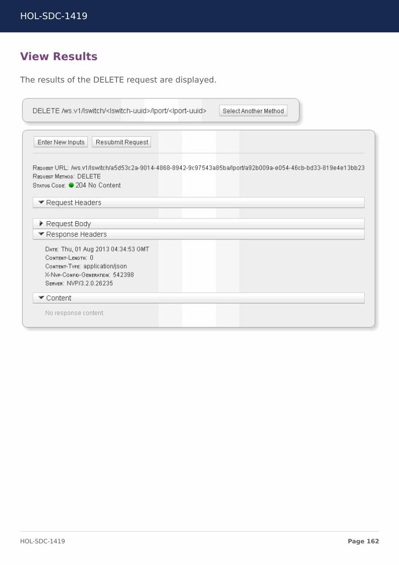
View Results
The results of the DELETE request are displayed.
HOL-SDC-1419
Page 162HOL-SDC-1419

Verify Deletion
From Dashboard, in the Summary of Logical Components section, click on numbernext to Switch Ports. You should not see the web-sv-03a switch port in the list.
The port mapped to web-sv-03a VM has been deleted and the VM can be attached toany other logical switch.
Create Logical Switch
Create a new logical switch called Test using the NSX API.
Create Test Logical Switch
In the API Inspector search box, type "create logical" to filter the list of API calls.
Select Create a Logical Switch
HOL-SDC-1419
Page 163HOL-SDC-1419

Enter parameters
Enter the following:
• display_name = Test• zone_uuid = Global-TZ• transport_type = stt
(click on the + next to Transport Zone to show more fields)
Click Submit Request
HOL-SDC-1419
Page 164HOL-SDC-1419

HOL-SDC-1419
Page 165HOL-SDC-1419

View Results
The request generates the following response from the NSX Controller.
• Status Code 201 Created means the POST request was successful.• The request body has the URI tokens entered previously in JSON format.• The response body has the UUID of the new Test logical switch.
Create Logical Switch Port
Create a Logical Switch Port on the Test Logical Switch
HOL-SDC-1419
Page 166HOL-SDC-1419

Create Logical Switch Port
In the API Inspector search box, type "create logical" to filter the list of API calls.
Select Create a Logical Switch Port
HOL-SDC-1419
Page 167HOL-SDC-1419

Enter parameters
Enter the following:
• lswitch-uuid = Test• display_name = web-sv-03a
Click Submit Request
HOL-SDC-1419
Page 168HOL-SDC-1419

View Results
The request generates the following response from the NSX Controller.
• Status Code 201 Created means the POST request was successful.• The request body has the URI tokens entered previously in JSON format.• The response body has the UUID of the new logical port.
Update Logical Switch Port Attachment
The final step is to attach web-sv-03a to the previously created Logical Switch Port.
HOL-SDC-1419
Page 169HOL-SDC-1419

Update Logical Switch Port Attachment
In the API Inspector search box, type "attachment" to filter the list of API calls.
Select Update Logical Switch Port Attachment
HOL-SDC-1419
Page 170HOL-SDC-1419

Enter parameters
Enter the following:
• lswitch-uuid = Test• lport-uuid = web-sv-03a• vif_uuid = (choose the MAC address ending in e5:71)
(Click on the Request Body drop down and choose VifAttachment)
Click Submit Request
View Results
The request generates the following response from the NSX Controller.
• Status Code 200 OK means UPDATE request was successful.• The request body has the URI tokens entered previously in JSON format.
HOL-SDC-1419
Page 171HOL-SDC-1419

• The response body has the VIF UUID of the attached VIF.
HOL-SDC-1419
Page 172HOL-SDC-1419

Verify Results
Navigate within NSX Manager to view the results of the API calls. There should be:
• Test Logical Switch• web-sv-03a Logical Switch Port
The API Inspector is a powerful tool that significantly simplifies integration with the NSXAPI.
HOL-SDC-1419
Page 173HOL-SDC-1419

Using the REST clientThe developer has completed development and testing of the web server in the isolatednetwork. The web server needs to be moved back to the Web-Tier network.
Use a standard REST client to invoke the NSX API calls for migrating web-sv-03a backto the Web-Tier network.
Detach web-sv-03a
Before web-sv-03a can be attached to another logical switch, delete the current logicalport attachment.
Delete Logical Switch Port
From NSX Manager, navigate to the list of logical switch ports.
Click on the gear on the right of web-sv-03a and select Delete
REST Overview
Representational state transfer (REST) defines a set of simple principles which areloosely followed by most API implementations. REST leverages strength and constraintsof HTTP to send data (Headers and Bodies) between Clients and Servers. REST elementsinclude:
• Resource (the object- the source of specific information)• Global Permanent Identifier (every resource is uniquely identified - i.e. HTTP URI)• Standard Interface (used to exchange the representation of resources (i.e. HTTP
protocol)
HOL-SDC-1419
Page 174HOL-SDC-1419

REST Client
From the desktop, launch the Firefox web browser.
Click on the RESTClient icon to launch the extension.
HOL-SDC-1419
Page 175HOL-SDC-1419

Set Content Type
Click on Headers and select Custom Header {20}
• Name: Content-Type• Value: application/x-www-form-urlencoded
Click Okay
HOL-SDC-1419
Page 176HOL-SDC-1419

Login
To interact with the NSX API, first login and retrieve an authentication token. {21}
Set the following:
• Method: POST• URL: https://nsx-ctl-01a/ws.v1/login• Headers: Content-Type: application/x-www-form-urlencoded• Body: username=admin&password=admin
Click SEND
NOTE: If you receive a 404 error, (Tools > Clear Recent History > Select Cache > ClearNow) flush the firefox cache, and relaunch the browser.
HOL-SDC-1419
Page 177HOL-SDC-1419

Login Response
The POST request response is displayed below.
Select and copy the nvp_sessionid value
HOL-SDC-1419
Page 178HOL-SDC-1419

Set cookie
Add a new custom header
• Name: set-cookie• Value: <paste previously copied nvp_sessionid>
Click Okay
NOTE: If a subsequent API request fails due to authentication, relogin to get a newtoken.
Create Logical Switch Port
Create a Logical Switch Port on the Web-Tier Logical Switch
HOL-SDC-1419
Page 179HOL-SDC-1419

Create Logical Switch Port
In the API Inspector search box, type "create logical" to filter the list of API calls.
Select Create a Logical Switch Port
HOL-SDC-1419
Page 180HOL-SDC-1419

Enter parameters
Enter the following:
• lswitch-uuid = Web-Tier• display_name = web-sv-03a
Clickon Show Formatted Request
HOL-SDC-1419
Page 181HOL-SDC-1419

View Formatted Request
The formatted request to create a logical switch port is displayed.
Copy the Request URL and Request BODY into the RESTClient as specified in the nextstep.
The Content-Type specified in the Request Headers will also be required in the nextstep.
Submit request via RESTClient
• URL:<paste the formatted request URI into the RESTClient with URL prefix ofhttps://nsx-ctl-01a>
• Method: POST• Content-Type: application/json; charset=utf-8
Request Body:
{
"display_name": "web-sv-03a",
"type": "LogicalSwitchPortConfig"
}
HOL-SDC-1419
Page 182HOL-SDC-1419

The Request Body can also be copied and pasted from the API Inspector
Click SEND
View Results
The request generates the following response from the NSX Controller.
• Status Code 201 Created means the POST request was successful.• The request body has the URI tokens entered previously in JSON format.• The response body has the UUID of the new logical port.
Update Logical Switch Port Attachment
The final step is to attach web-sv-03a to the previously created Logical Switch Port.
HOL-SDC-1419
Page 183HOL-SDC-1419

Update Logical Switch Port Attachment
In the API Inspector search box, type "attachment" to filter the list of API calls.
Select Update Logical Switch Port Attachment
HOL-SDC-1419
Page 184HOL-SDC-1419

Enter parameters
Enter the following:
• lswitch-uuid = Web-Tier• lport-uuid = web-sv-03a• vif_uuid = (choose the MAC address ending in e5:71)
(Click on the Request Body drop down and choose VifAttachment)
Click Show Formatted Request
HOL-SDC-1419
Page 185HOL-SDC-1419

View Formatted Request
The formatted request to update a logical switch port attachment is displayed.
Copy the Request URL and Request Body into the RESTClient as specified in the nextstep.
HOL-SDC-1419
Page 186HOL-SDC-1419
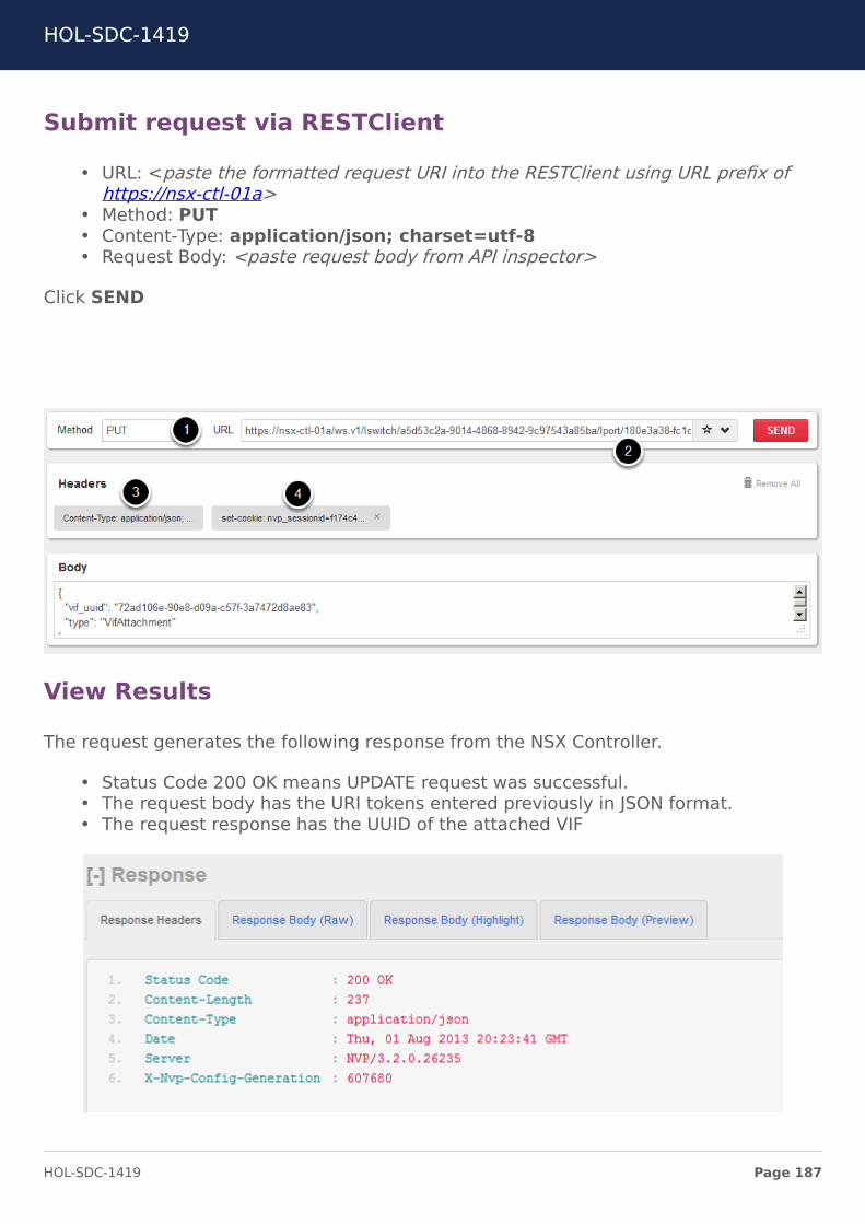
Submit request via RESTClient
• URL: <paste the formatted request URI into the RESTClient using URL prefix ofhttps://nsx-ctl-01a>
• Method: PUT• Content-Type: application/json; charset=utf-8• Request Body: <paste request body from API inspector>
Click SEND
View Results
The request generates the following response from the NSX Controller.
• Status Code 200 OK means UPDATE request was successful.• The request body has the URI tokens entered previously in JSON format.• The request response has the UUID of the attached VIF
HOL-SDC-1419
Page 187HOL-SDC-1419

Verify Results
Navigate within NSX Manager to view the results of the API calls. The third web server isreconnected to Web-Tier logical switch.
HOL-SDC-1419
Page 188HOL-SDC-1419

Module 7 –Troubleshooting
HOL-SDC-1419
Page 189HOL-SDC-1419

Port ConnectionsBeing able to quickly monitor and troubleshoot networking issues in the logical andphysical space is of paramount importance. Just as server virtualization led to newinnovations in the management space, tools built on top of network virtualizationplatforms can provide similar benefits.
NSX Manager includes a Port Connections Tool to test connectivity between a pair oflogical ports. It provides a visual depiction of all forwarding elements required in orderto provide network forwarding between logical ports.
Important Note: Lab Fast Forward Script
Modules 2 and 3 are required to be completed before you continue with this module. Wehave created a python script "fast-forward-nsx.py" to complete those modules for youso that you can proceed with the lab. Please refer to the Lab Fast Forward Script sectionin Module 5 for detailed instructions on running the script.
Port Connections Tool
The Port Connections Tool accepts input for logical ports on a given logical switch andreturns detailed information about the relevant logical and transport layer components.This allows the operator to quickly visualize the path between a given pair of logicalports and troubleshoot any problems that may be present. The sections of the tool aresummarized below.
• VM – displays UUID/MAC information for VMs connected to each lport• Logical Switch Port – displays the status of each lport• Logical Forwarding Elements – displays the status of the logical components used
to forward traffic between the lports (eg. lswitches)• Transport Node – displays status and bridge information for each NVP component
involved in forwarding traffic between the lports• Transport Connector – displays status of each transport connector used for data
forwarding.• Tunnels – displays status for tunnels used between transport nodes• Traceflow – used to inject traffic into logical space. see following slides.
HOL-SDC-1419
Page 190HOL-SDC-1419

Access Port Connections
Mouse over Tools & Troubleshooting tab then select Port Connections
Verify logical port to logical port connectivity on the samelogical switch
Select Web-Tier as the Logical switch.
Select web-sv-01a and web-sv-02a for Logical Switch Ports
Click Go
Click on All Sections: Expand
VM Section
View the VM section. This displays MAC and UUID information of the connected Webvirtual machines.
HOL-SDC-1419
Page 191HOL-SDC-1419

Logical Switch Port
View the Logical Switch Port section. This shows information on the status of the logicalswitches and their associated UUIDs.
Logical Forwarding Elements
View Logical Forwarding Elements. This displays information about the the logical switchand the logical router that the virtual machines are connected to.
Traceflow
View Traceflow, click the Ping button that corresponds to the source port from whichthe test packet will be injected. A result of Delivered indicates success. To see a moredetailed trace of the packet’s route, use the Logical Switch Port inspector page asexplained in the next section.
NOTE: If the Destination Port is not a VIF Attachment, Traceflow will send a broadcast.The button text changes to Broadcast Ping to indicate this.
Transport Nodes
View Transport Nodes. This gives information of the hypervisors and the integrationbridges on which these virtual machines are provisioned.
HOL-SDC-1419
Page 192HOL-SDC-1419

Review the information associated with the NSX vSwitch integration bridge on the ESXihost and the Open vSwitch integration bridge on the KVM host.
Transport Connectors
View Transport Connections. This gives information on the tunneling protocol used, theTransport Zone UUID, and the IP address end points for the tunnels (the ESXi and KVMHypervisors).
HOL-SDC-1419
Page 193HOL-SDC-1419

Tunnels
This is the most popular view, showing a graphical view of all the components necessaryfor end-to-end connectivity.
Green arrows indicate that unidirectional tunnels are up between the components(Hypervisors, Service Nodes, and Gateways)
HOL-SDC-1419
Page 194HOL-SDC-1419

Logical Port MonitoringNSX provides the ability to monitor workloads attached to logical ports. A workload is atenant virtual machine or a physical application attached to a logical port. Workloadsand logical ports are logical entities in NSX, and this allows NSX to ensure that thenetwork policies and statistics associated with a workload follow that workload when itis moved in the NSX domain.
Logical Port Statistics
Logical port counters provide statistics information about the actual workload or VLANattached to a logical port. The statistics remain associated with the virtual machine,even when the virtual machine is powered down or migrated within the NSX domain.
Collect port statistics
From the API Inspector, select the Read Logical Switch Port Statistics API
HOL-SDC-1419
Page 195HOL-SDC-1419

Enter URI Tokens
• lswitch-uuid = Web-Tier• lport-uuid = web-sv-01a
Click Submit Request
HOL-SDC-1419
Page 196HOL-SDC-1419

View Response
The response gives the port statistics for the web-sv-01a virtual machine.
NOTE: If the port statistics are showing all values to be zero, start a ping to the web-sv-01 (172.16.10.11) from the command line of the control center and redo the APIrequest.
HOL-SDC-1419
Page 197HOL-SDC-1419

TraceflowTraceflow
Traceflow is used to inject traffic into logical space and provides a mechanism to testconnectivity between a pair of logical ports. Keep the following in mind when using thetool:
• Traceflow injects ICMP echo requests directly into the virtual switch at the bridgeport where the virtual machine is connected.
• The virtual machine on either side of the connection never see the data injectedby Traceflow since it originates and terminates directly within the virtual switchitself
• Traceflow cannot detect connectivity issues beyond the logical switch port level.For instance, Traceflow cannot detect whether the virtual machine is filtering orwhether the network beyond a Gateway is filtering or otherwise problematic.
Port Connections includes a simple Traceflow validation method.
From the dashboard, click on the number next to Switch Ports.
HOL-SDC-1419
Page 198HOL-SDC-1419

Select the Logical Switch Port
Click on the web-sv-01a logical switch port
Inject Traceflow
In the Traceflow section click Inject.
Build a packet to be injected
In the Inject Packet window, choose the Source MACand Destination MACaddresses.
HOL-SDC-1419
Page 199HOL-SDC-1419

Source MAC = web-sv-01 MAC address = 00:50:56:87:28:c3
Destination MAC = web-sv-02a MAC address = 52:54:00:08:03:71
You may provide a Payload for the packet. If a payload is not provided, a defaultpayload is inserted.
Choose the Frame Size. Be sure toleave sufficient space for all headers and thepayload you are sending. For this example, 1500 is used.
Specify the Timeout in milliseconds (min. 1000 ms; max. 10000 ms). This specifies howlong Traceflow will wait to observe whether the packet has been delivered to alldestinations in the Logical Switch.
Select Ethertype to be an IP packet.
Click Save
Interpret Traceflow Results
If the test produces observations, the results display a Delivered summary row and a setof per-hop observation rows.
Summary results
The summary row shows the following information:
HOL-SDC-1419
Page 200HOL-SDC-1419

• Response: OK if the packet successfully reached its destination; Error otherwise.
• Delivered: Delivered or Not Delivered. A status of Delivered indicates the packet wasdelivered to all destinations successfully.
• Source and Destination MAC address
• Frame Size: Total size of test packet, including headers
• Ethertype: Type of test packet sent.
• Observations: How many times the packet was observed being forwarded ordelivered.
• Forwards: How many times the packet was forwarded.
• Timeout: User-specified length of this test in milliseconds. Traceflow reports allforwards and deliveries that occur within this period. Do not confuse this withTimestamp Delta (ms), described below.
• Time Stamp: Time when this test started.
Per-hop results
For a given test, the Traceflow results also display one row per hop in the packet’straversal of the Logical Switch. Each row shows:
• Type: Whether this hop represented forwarding or delivery.
• Source and Destination Transport Node: These are links to the Transport Nodeinspector page for the starting and ending node of this hop.
• Timestamp Delta (ms): Elapsed time in milliseconds from start of test until the NSXController received the observation of this hop.
• Remote IP Address: Shown only for forwards, this is the IP address to which thepacket was forwarded.
• Connector:Shown only for forwards, this is the Transport Zone on which the packetwas forwarded.
• Logical Port: Shown only for deliveries, this is the logical port to which the packetwas delivered.
HOL-SDC-1419
Page 201HOL-SDC-1419

HOL-SDC-1419
Page 202HOL-SDC-1419

ConclusionCongratulations on completing the NSX lab and joining the network virtualizationrevolution! In the lab you demonstrated the power and flexibility of NSX by:
• Connecting virtual machines across hypervisors and networks through LogicalSwitches
• Routing virtual machines across Logical Switches through Logical Routers and L3Gateway Services
• Migrating a server to a Logical Switch while maintaining connectivity bypreserving the IP address
• Using security controls to secure Logical Switches• Exploring the NSX API Inspector and various troubleshooting options
For more information, visit the VMware booth in the Solutions Exchange. Also check outthe following sessions:
• NET5184 Designing Your Next Generation Datacenter for Network Virtualization• NET5516 An Introduction to Network Virtualization• NET5716 Advanced VMware NSX Architecture• NET7388-S Network Virtualization: Moving Beyond the Obvious
HOL-SDC-1419
Page 203HOL-SDC-1419

ConclusionThank you for participating in the VMware Hands-on Labs. Be sure to visithttp://hol.vmware.com/ to continue your lab experience online.
Lab SKU: HOL-SDC-1419
Version: 20150227-060847
HOL-SDC-1419
Page 204HOL-SDC-1419
Related Documents


