Table of Contents A Phone: (605) 225-0360 Fax: (605) 225-0567 HELICAL GEAR UNITS . . . . . . . . . . . . . . . . . . . . . . . . . . . . . . . . . . . . . .A2 ACCESSORIES . . . . . . . . . . . . . . . . . . . . . . . . . . . . . . . . . . . . . . . . . . . .A3 REDUCER APPLICATION DATA . . . . . . . . . . . . . . . . . . . . . . . . . . . . .A4-A6 CONCENTRIC SHAFT REDUCERS HP & TORQUE RATINGS 1750 RPM . . . . . . . . . . . . . . . . . . . . . . . . . . . . . . . . . . . . . . .A7 1450 RPM . . . . . . . . . . . . . . . . . . . . . . . . . . . . . . . . . . . . . . .A8 1170 RPM . . . . . . . . . . . . . . . . . . . . . . . . . . . . . . . . . . . . . . .A9 870 RPM . . . . . . . . . . . . . . . . . . . . . . . . . . . . . . . . . . . . . . .A10 580 RPM . . . . . . . . . . . . . . . . . . . . . . . . . . . . . . . . . . . . . . .A11 TABLES OF ACTUAL RATIOS . . . . . . . . . . . . . . . . . . . . . . . . . . . . . . . .A12 OVERHUNG LOAD CAPACITIES IN POUNDS-OUTPUT SHAFT . . . . .A13 OVERHUNG LOAD CAPACITIES IN POUNDS-INPUT SHAFT . . .A14-A15 GEAR REDUCER DIMS. . . . . . . . . . . . . . . . . . . . . . . . . . . . . . . . . .A16-A21 DOUBLE REDUCTION . . . . . . . . . . . . . . . . . . . . . . . .A16-A17 TRIPLE REDUCTION . . . . . . . . . . . . . . . . . . . . . . . . .A18-A19 QUADRUPLE REDUCTION . . . . . . . . . . . . . . . . . . . . .A20-A21 BASEMOUNT HORZ. GEAR REDUCER DIMENSIONS DOUBLE REDUCTION . . . . . . . . . . . . . . . . . . . . . . . . . . . .A22 TRIPLE REDUCTION . . . . . . . . . . . . . . . . . . . . . . . . . . . . .A23 QUADRUPLE REDUCTION . . . . . . . . . . . . . . . . . . . . . . . .A24 REDUCERS W/COOLING FAN DIMS. . . . . . . . . . . . . . . . . . . . . . . . . . .A25 LINE-O-MOUNT HORZ. GEAR REDUCER DIMS. DOUBLE REDUCTION . . . . . . . . . . . . . . . . . . . . . . . .A26-A27 TRIPLE REDUCTION . . . . . . . . . . . . . . . . . . . . . . . . .A28-A29 WK 2 VALUES . . . . . . . . . . . . . . . . . . . . . . . . . . . . . . . . . . . . . . . . . . . . .A30 LINE-O- POWER ™ Concentric Shaft Reducers

Welcome message from author
This document is posted to help you gain knowledge. Please leave a comment to let me know what you think about it! Share it to your friends and learn new things together.
Transcript
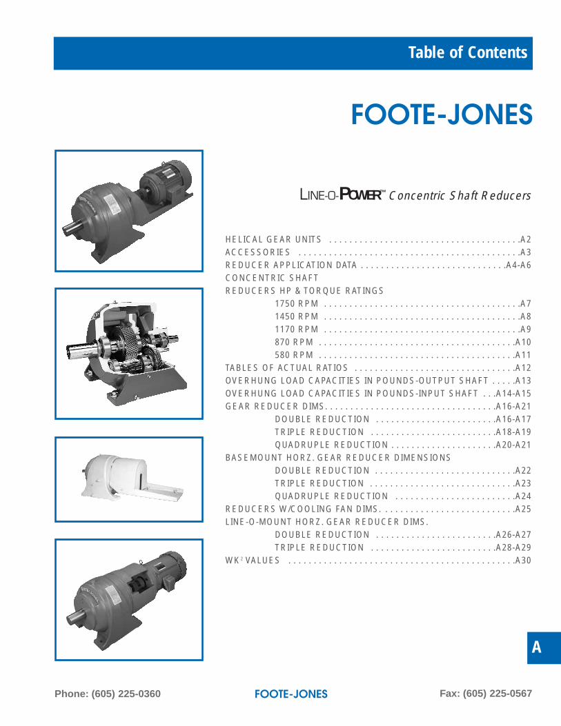
Table of Contents
A
Phone: (605) 225-0360 Fax: (605) 225-0567
HELICAL GEAR UNITS . . . . . . . . . . . . . . . . . . . . . . . . . . . . . . . . . . . . . .A2ACCESSORIES . . . . . . . . . . . . . . . . . . . . . . . . . . . . . . . . . . . . . . . . . . . .A3REDUCER APPLICATION DATA . . . . . . . . . . . . . . . . . . . . . . . . . . . . .A4-A6CONCENTRIC SHAFT REDUCERS HP & TORQUE RATINGS
1750 RPM . . . . . . . . . . . . . . . . . . . . . . . . . . . . . . . . . . . . . . .A71450 RPM . . . . . . . . . . . . . . . . . . . . . . . . . . . . . . . . . . . . . . .A81170 RPM . . . . . . . . . . . . . . . . . . . . . . . . . . . . . . . . . . . . . . .A9870 RPM . . . . . . . . . . . . . . . . . . . . . . . . . . . . . . . . . . . . . . .A10580 RPM . . . . . . . . . . . . . . . . . . . . . . . . . . . . . . . . . . . . . . .A11
TABLES OF ACTUAL RATIOS . . . . . . . . . . . . . . . . . . . . . . . . . . . . . . . .A12OVERHUNG LOAD CAPACITIES IN POUNDS-OUTPUT SHAFT . . . . .A13OVERHUNG LOAD CAPACITIES IN POUNDS-INPUT SHAFT . . .A14-A15GEAR REDUCER DIMS. . . . . . . . . . . . . . . . . . . . . . . . . . . . . . . . . .A16-A21
DOUBLE REDUCTION . . . . . . . . . . . . . . . . . . . . . . . .A16-A17TRIPLE REDUCTION . . . . . . . . . . . . . . . . . . . . . . . . .A18-A19QUADRUPLE REDUCTION . . . . . . . . . . . . . . . . . . . . .A20-A21
BASEMOUNT HORZ. GEAR REDUCER DIMENSIONSDOUBLE REDUCTION . . . . . . . . . . . . . . . . . . . . . . . . . . . .A22TRIPLE REDUCTION . . . . . . . . . . . . . . . . . . . . . . . . . . . . .A23QUADRUPLE REDUCTION . . . . . . . . . . . . . . . . . . . . . . . .A24
REDUCERS W/COOLING FAN DIMS. . . . . . . . . . . . . . . . . . . . . . . . . . .A25LINE-O-MOUNT HORZ. GEAR REDUCER DIMS.
DOUBLE REDUCTION . . . . . . . . . . . . . . . . . . . . . . . .A26-A27TRIPLE REDUCTION . . . . . . . . . . . . . . . . . . . . . . . . .A28-A29
WK2 VALUES . . . . . . . . . . . . . . . . . . . . . . . . . . . . . . . . . . . . . . . . . . . . .A30
LINE-O-POWER™ Concentric Shaft Reducers

Phone: (605) 225-0360 Fax: (605) 225-0567
Helical Gear UnitsA2
LINE-O-POWER™ Concentric Shaft Reducers
SELECT THE TYPE OF HELICAL GEAR UNIT YOU NEED
Type SLMultiple Reduction HelicalHorizontal Foot Mount
Type VSLMultiple Reduction HelicalVertical Flange Mount
Type PSLMultiple ReductionHelical with Motor Mount
Type BSLMultiple ReductionHelical with Baseplate
Type KSLMultiple ReductionHelical with Backstop
Type LMultiple Reduction HelicalHorizontal Foot Mount with Motor Scoop
Type CMultiple Reduction HelicalHorizontal Foot Mount with “C” Face Motor Mount
Type VLMultiple Reduction HelicalVertical Flange Mount with Motor Scoop
Type VCMultiple Reduction HelicalVertical Flange Mount with“C” Face Motor Mount
Line-O-Motor Coupled Gearmotor Line-O-Motor NEMA“C”-Face Coupled Gearmotor
Web: www.footejones.comE-mail: [email protected]
Accessories A3
A
LINE-O-POWER™ Concentric Shaft Reducers
The 800 Series line of Concentric Shaft Speed Reducershas the latest state-of-the art engineering improvements,using higher capacity bearings, selectively ground orskived gearing, and larger diameter shafts.
There are ten sizes up to 429,300 inch pounds outputtorque. Double, triple, and quadruple reduction units areavailable in modular design. The surface hardened helicalgearing is rated in accordance with applicable AGMAstandards.
Tapered roller bearings on all shafts provide anticipatedbearing life in excess of AGMA standards and normalindustry requirements.
Housings are made of Cast Iron in the eight smaller sizes.The two larger sizes have fabricated steel housings.Dual lip oil seals on input and output shafts, with option forgrease purging available.
Available adaptations are: Vertical ring mount adapter –low speed shaft down, scoop motor mount, C face motormount, motor mount for V belt drive, and common base-plate. Available accessories also include backstop, slidebase, standard or OSHA guards, cooling fan, heatexchanger and special assemblies.
BACKSTOPThe ratchet and pawl type backstop isavailable for in line reducers as a stan-dard accessory to prevent reversal ofshaft rotation, and may be used asfrequently as needed; it is mounted onthe high speed shaft extension. Thepawls pivot on oilite bearings eliminatingthe need for relubricating. The entirebackstop is enclosed in a dust-tight casesuitable for use in dirty atmosphere.
When ordering a reducer with backstop, it is important toclearly state the required direction of free rotation of theoutput shaft when viewing reducer at the low speed end.Backstop not available when cooling fan is used.
Our Backstops Do Not run in oil.
COOLING FANFor applications wheremechanical horsepowerrequirements exceed reducerthermal capacities, thecooling fan provides an inexpensive way to dissipateexcessive heat. The coolingfan adds approximately 25% to catalog thermal ratings.Where additional cooling is needed, a forced feed oilsystem with heat exchanger can be furnished.
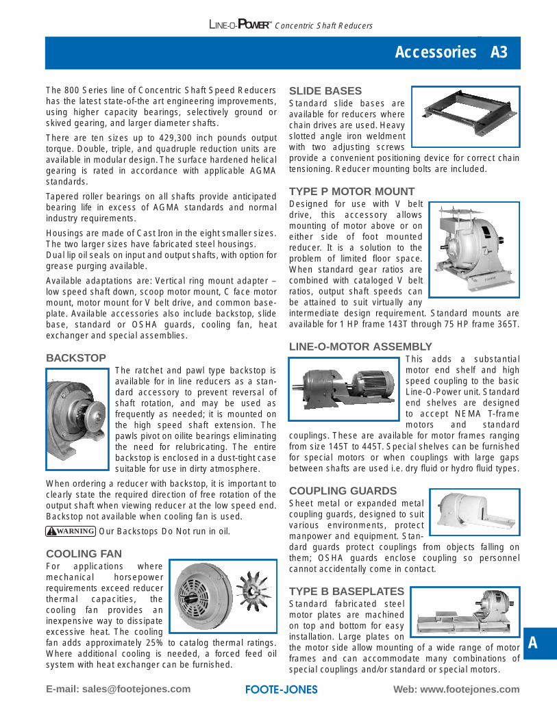
SLIDE BASESStandard slide bases areavailable for reducers wherechain drives are used. Heavyslotted angle iron weldmentwith two adjusting screwsprovide a convenient positioning device for correct chaintensioning. Reducer mounting bolts are included.
TYPE P MOTOR MOUNTDesigned for use with V beltdrive, this accessory allowsmounting of motor above or oneither side of foot mountedreducer. It is a solution to theproblem of limited floor space.When standard gear ratios arecombined with cataloged V beltratios, output shaft speeds canbe attained to suit virtually anyintermediate design requirement. Standard mounts areavailable for 1 HP frame 143T through 75 HP frame 365T.
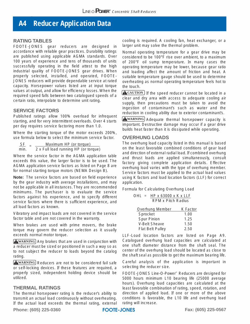
LINE-O-MOTOR ASSEMBLYThis adds a substantialmotor end shelf and highspeed coupling to the basicLine-O-Power unit. Standardend shelves are designed to accept NEMA T-framemotors and standard
couplings. These are available for motor frames rangingfrom size 145T to 445T. Special shelves can be furnishedfor special motors or when couplings with large gapsbetween shafts are used i.e. dry fluid or hydro fluid types.
COUPLING GUARDSSheet metal or expanded metalcoupling guards, designed to suitvarious environments, protectmanpower and equipment. Stan-dard guards protect couplings from objects falling onthem; OSHA guards enclose coupling so personnelcannot accidentally come in contact.
TYPE B BASEPLATESStandard fabricated steelmotor plates are machinedon top and bottom for easyinstallation. Large plates onthe motor side allow mounting of a wide range of motorframes and can accommodate many combinations ofspecial couplings and/or standard or special motors.
WARNING
Phone: (605) 225-0360 Fax: (605) 225-0567
Reducer Application DataA4
LINE-O-POWER™ Concentric Shaft Reducers
RATING TABLESFOOTE-JONES gear reducers are designed in accordance with reliable gear practices. Durability ratingsare published using applicable AGMA standards. Over100 years of experience and tens of thousands of unitssuccessfully operating in the field attest to the high industrial quality of FOOTE-JONES gear drives. Whenproperly selected, installed, and operated, FOOTE-JONES reducers will provide dependable service at ratedcapacity. Horsepower values listed are at input torquevalues at output, and allow for efficiency losses. When therequired speed falls between two catalogued speeds of acertain ratio, interpolate to determine unit rating.
SERVICE FACTORSPublished ratings allow 100% overload for infrequentstarting, and for very intermittent overloads. Over 4 startsper day requires service factoring more than 1.0.
Where the starting torque of the motor exceeds 200%,use formula below to select the minimum service factor.
SF = Maximum HP (or torque)min. 2 x Full load running HP (or torque)
Where the service factor in the AGMA application tableexceeds this value, the larger factor is to be used. TheAGMA application service factors as listed on Page 8 arefor normal starting torque motors (NEMA Design B).
Note: The service factors are based on field experienceby the gear industry with average installations, and maynot be applicable in all instances. They are recommendedminimums. The purchaser is to evaluate the servicefactors against his experience, and to specify differentservice factors where there is sufficient experience, andall load factors as known.
Vibratory and impact loads are not covered in the servicefactor table and are not covered in the warranty.
When brakes are used with prime movers, the braketorque may govern the reducer selection as it usuallyexceeds normal motor torque.
Any brakes that are used in conjunction witha reducer must be sized or positioned in such a way so asto not subject the reducer to loads beyond the catalograting.
Reducers are not to be considered fail safeor self-locking devices. If these features are required, aproperly sized, independent holding device should beutilized.
THERMAL RATINGSThe thermal horsepower rating is the reducer’s ability totransmit an actual load continuously without overheating.If the actual load exceeds the thermal rating, external
cooling is required. A cooling fan, heat exchanger, or alarger unit may solve the thermal problem.
Normal operating temperature for a gear drive may beconsidered to be 100°F rise over ambient, to a maximumof 200°F oil sump temperature. In many cases the operating temperature may be lower, because gear ratioand loading affect the amount of friction and heat. A suitable temperature gauge should be used to determineoverheating as normal operating temperature feels hot tothe touch.
If the speed reducer cannot be located in aclear and dry area with access to adequate cooling airsupply, then precautions must be taken to avoid the ingestion of contaminant’s such as water and the reduction in cooling ability due to exterior contaminant’s.
Adequate thermal horsepower capacity is important. Destructive damage may occur if a gear drive builds heat faster than it is dissipated while operating.
OVERHUNG LOADSThe overhung load capacity listed in this manual is basedon the least favorable combined conditions of gear loadand direction of external radial load. If combined overhungand thrust loads are applied simultaneously, consultfactory giving complete application details. Effective overhung load varies with the type of overhung member.Service factors must be applied to the actual load valuesusing K factors and load location factors (LLF) for correctapplication.
Formula for Calculating Overhung Load
OHL = HP x 63000 x K x LLFRPM x Pitch Radius
Overhung Member K FactorSprocket 1.00Spur Pinion 1.25V-Belt Sheave 1.50Flat Belt Pulley 2.50
LLF-Load location factors are listed on Page A9.Catalogued overhung load capacities are calculated atone shaft diameter distance from the shaft seal. Thecenter of the overhung load should be located as close tothe shaft seal as possible to get the maximum bearing life.
Careful analysis of the application is important inselecting the reducer size.
FOOTE-JONES Line-O-Power™ Reducers are designed for5000 hours minimum L10 bearing life (25000 averagehours). Overhung load capacities are calculated at theleast favorable combination of rating, speed, rotation, anddirection of applied load. If one or more of the aboveconditions is favorable, the L10 life and overhung loadrating will increase.
WARNING
CAUTION
WARNING
WARNING
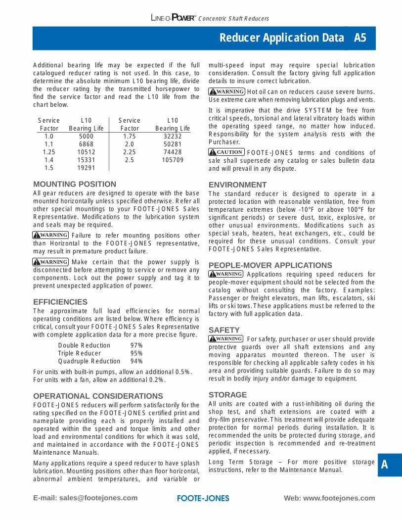
Additional bearing life may be expected if the full catalogued reducer rating is not used. In this case, todetermine the absolute minimum L10 bearing life, dividethe reducer rating by the transmitted horsepower to find the service factor and read the L10 life from the chart below.
Service L10 Service L10Factor Bearing Life Factor Bearing Life
1.0 5000 1.75 322321.1 6868 2.0 502811.25 10512 2.25 744281.4 15331 2.5 1057091.5 19291
MOUNTING POSITIONAll gear reducers are designed to operate with the basemounted horizontally unless specified otherwise. Refer allother special mountings to your FOOTE-JONES SalesRepresentative. Modifications to the lubrication systemand seals may be required.
Failure to refer mounting positions otherthan Horizontal to the FOOTE-JONES representative,may result in premature product failure.
Make certain that the power supply isdisconnected before attempting to service or remove anycomponents. Lock out the power supply and tag it toprevent unexpected application of power.
EFFICIENCIESThe approximate full load efficiencies for normal operating conditions are listed below. Where efficiency iscritical, consult your FOOTE-JONES Sales Representativewith complete application data for a more precise figure.
Double Reduction 97%Triple Reducer 95%Quadruple Reduction 94%
For units with built-in pumps, allow an additional 0.5%.For units with a fan, allow an additional 0.2%.
OPERATIONAL CONSIDERATIONSFOOTE-JONES reducers will perform satisfactorily for therating specified on the FOOTE-JONES certified print andnameplate providing each is properly installed and operated within the speed and torque limits and otherload and environmental conditions for which it was sold,and maintained in accordance with the FOOTE-JONESMaintenance Manuals.
Many applications require a speed reducer to have splashlubrication. Mounting positions other than floor horizontal,abnormal ambient temperatures, and variable or
multi-speed input may require special lubrication consideration. Consult the factory giving full applicationdetails to insure correct lubrication.
Hot oil can on reducers cause severe burns.Use extreme care when removing lubrication plugs and vents.
It is imperative that the drive SYSTEM be free from critical speeds, torsional and lateral vibratory loads withinthe operating speed range, no matter how induced.Responsibility for the system analysis rests with thePurchaser.
FOOTE-JONES terms and conditions ofsale shall supersede any catalog or sales bulletin dataand will prevail in any dispute.
ENVIRONMENTThe standard reducer is designed to operate in aprotected location with reasonable ventilation, free fromtemperature extremes (below -10°F or above 100°F forsignificant periods) or severe dust, toxic, explosive, orother unusual environments. Modifications such asspecial seals, heaters, heat exchangers, etc., could berequired for these unusual conditions. Consult yourFOOTE-JONES Sales Representative.
PEOPLE-MOVER APPLICATIONSApplications requiring speed reducers for
people-mover equipment should not be selected from thecatalog without consulting the factory. Examples:Passenger or freight elevators, man lifts, escalators, skilifts or ski tows. These applications must be referred to thefactory with full application data.
SAFETYFor safety, purchaser or user should provide
protective guards over all shaft extensions and anymoving apparatus mounted thereon. The user is responsible for checking all applicable safety codes in hisarea and providing suitable guards. Failure to do so mayresult in bodily injury and/or damage to equipment.
STORAGEAll units are coated with a rust-inhibiting oil during theshop test, and shaft extensions are coated with a dry-film preservative. This treatment will provide adequateprotection for normal periods during installation. It isrecommended the units be protected during storage, andperiodic inspection is recommended and re-treatmentapplied, if necessary.
Long Term Storage – For more positive storage instructions, refer to the Maintenance Manual.
Web: www.footejones.comE-mail: [email protected]
Reducer Application Data A5
A
LINE-O-POWER™ Concentric Shaft Reducers
WARNING
WARNING
WARNING
CAUTION
WARNING
WARNING

Phone: (605) 225-0360 Fax: (605) 225-0567
Reducer Application DataA6
LINE-O-POWER™ Concentric Shaft Reducers
SELECTION EXAMPLE:
APPLICATION:Skip Hoist 8 hrs./day using a 7-1/2 HP AC electric motor, high torque 5-8% slip (275% starting torque) 1690 RPM, at68 RPM output; input shaft is coupling connected, output shaft has chain drive using 8.0 inch PD sprocket with centerof load at midpoint of standard catalog shaft keyway.
Selection ProcedureA. Determine service factor from AGMA load
classification table on Section K.Determine minimum service factor from formula on Page A4 SFmin.
B. Calculate equivalent horsepower.(Transmitted HP x service factor)
C. Determine RatioInput RPMOutput RPM
D. Determine reducer size. Interpolate rating for 1690 RPM. Select reducer from 1750 RPM table on PageA7 for 10.31 HP.
E. Check rating table for possible thermal problem, shaded area will indicate.Thermal capacity considers transmitted HP only, (not equivalent HP). Check for 7-1/2 HP.
F. Check overhung loadOHL = HP x 63000 x K x LLF
RPM x R
Selection ExampleA. 1.25
SFmin. = 2.75 x 71/2 = 2.75 = 1.3752 x 71/2 2
B. 7-1/2 x 1.375 = 10.31 HP
C. 1690 = 24.8:1.68
Use closest AGMA ratio 25.6:1
D. 1750 x 10.31 = 10.68 HP required in 1750 RPM table1690 Select size 822 SL, ratio 25.6:1HP rating is 1690 x 12.4 = 11.97 at 1690 RPM input
1750
E. No thermal problem.
F. 7-1/2 x 63000 x 1.00 x 1.0 = 1790 lbs.66 x 4
OHL capacity is 4051 lbs. from the Table on A13.
Web: www.footejones.comE-mail: [email protected]
Concentric Shaft Reducers HP & Torque Ratings A7
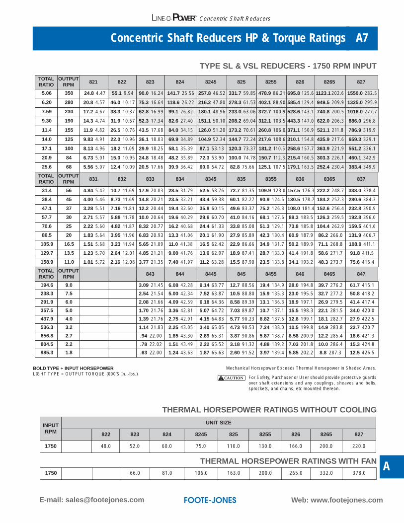
TYPE SL & VSL REDUCERS - 1750 RPM INPUT
TOTALRATIO
OUTPUTRPM 821 822 823 824 8245 825 8255 826 8265 827
5.06 350 24.8 4.47 55.1 9.94 90.0 16.24 141.7 25.56 257.8 46.52 331.7 59.85 478.9 86.21 695.8 125.6 1123.1 202.6 1550.0 282.5
6.20 280 20.8 4.57 46.0 10.17 75.3 16.64 118.6 26.22 216.2 47.80 278.3 61.53 402.1 88.90 585.4 129.4 949.5 209.9 1325.0 295.9
7.59 230 17.2 4.67 38.3 10.37 62.8 16.99 99.1 26.82 180.1 48.96 233.0 63.06 372.7 100.9 528.6 143.1 740.8 200.5 1016.0 277.7
9.30 190 14.3 4.74 31.9 10.57 52.3 17.34 82.6 27.40 151.1 50.10 208.2 69.04 312.1 103.5 443.3 147.0 622.0 206.3 886.0 296.8
11.4 155 11.9 4.82 26.5 10.76 43.5 17.68 84.0 34.15 126.0 51.20 173.2 70.61 260.8 106.0 371.1 150.9 521.1 211.8 786.9 319.9
14.0 125 9.83 4.91 22.0 10.96 36.1 18.03 69.9 34.89 104.9 52.34 144.7 72.24 217.6 108.6 310.1 154.8 435.9 217.6 659.3 329.1
17.1 100 8.13 4.96 18.2 11.09 29.9 18.25 58.1 35.39 87.1 53.13 120.3 73.37 181.2 110.5 258.6 157.7 363.9 221.9 551.2 336.1
20.9 84 6.73 5.01 15.0 10.95 24.8 18.48 48.2 35.89 72.3 53.90 100.0 74.78 150.7 112.3 215.4 160.5 303.3 226.1 460.1 342.9
25.6 68 5.56 5.07 12.4 10.09 20.5 17.66 39.9 36.42 60.0 54.72 82.8 75.66 125.1 107.5 179.1 163.5 252.4 230.4 383.4 349.9
TOTALRATIO
OUTPUTRPM 831 832 833 834 8345 835 8355 836 8365 837
31.4 56 4.84 5.42 10.7 11.69 17.9 20.03 28.5 31.79 52.5 58.76 72.7 81.35 109.9 123.0 157.5 176.3 222.2 248.7 338.0 378.4
38.4 45 4.00 5.46 8.73 11.69 14.8 20.21 23.5 32.21 43.4 59.38 60.1 82.27 90.9 124.5 130.5 178.7 184.2 252.3 280.6 384.3
47.1 37 3.28 5.51 7.16 11.81 12.2 20.44 19.4 32.60 35.8 60.15 49.6 83.37 75.2 126.3 108.0 181.4 152.6 256.4 232.8 390.9
57.7 30 2.71 5.57 5.88 11.78 10.0 20.64 19.6 40.29 29.6 60.70 41.0 84.16 68.1 127.6 89.3 183.5 126.3 259.5 192.8 396.0
70.6 25 2.22 5.60 4.82 11.87 8.32 20.77 16.2 40.68 24.4 61.33 33.8 85.08 51.3 129.1 73.8 185.8 104.4 262.9 159.5 401.6
86.5 20 1.83 5.64 3.95 11.96 6.83 20.93 13.3 41.06 20.1 61.90 27.9 85.89 42.3 130.4 60.9 187.9 86.2 266.0 131.9 406.7
105.9 16.5 1.51 5.68 3.23 11.94 5.65 21.09 11.0 41.38 16.5 62.42 22.9 86.66 34.9 131.7 50.2 189.9 71.1 268.8 108.9 411.1
129.7 13.5 1.23 5.70 2.64 12.01 4.85 21.21 9.00 41.76 13.6 62.97 18.9 87.41 28.7 133.0 41.4 191.8 58.6 271.7 91.8 411.5
158.9 11.0 1.01 5.72 2.16 12.08 3.77 21.35 7.40 41.97 11.2 63.28 15.5 87.90 23.5 133.8 34.1 193.2 48.3 273.7 75.6 415.4
TOTALRATIO
OUTPUTRPM 843 844 8445 845 8455 846 8465 847
194.6 9.0 3.09 21.45 6.08 42.28 9.14 63.77 12.7 88.56 19.4 134.9 28.0 194.8 39.7 276.2 61.7 415.1
238.3 7.5 2.54 21.54 5.00 42.34 7.52 63.87 10.5 88.80 15.9 135.3 23.0 195.5 32.7 277.2 50.8 418.2
291.9 6.0 2.08 21.66 4.09 42.59 6.18 64.36 8.58 89.39 13.1 136.3 18.9 197.1 26.9 279.5 41.4 417.4
357.5 5.0 1.70 21.76 3.36 42.81 5.07 64.72 7.03 89.87 10.7 137.1 15.5 198.3 22.1 281.5 34.0 420.0
437.9 4.0 1.39 21.76 2.75 42.91 4.15 64.83 5.77 90.23 8.82 137.6 12.8 199.1 18.1 282.7 27.9 422.5
536.3 3.2 1.14 21.83 2.25 43.05 3.40 65.05 4.73 90.53 7.24 138.0 10.5 199.8 14.9 283.8 22.7 420.7
656.8 2.7 .94 22.00 1.85 43.30 2.89 65.31 3.87 90.86 5.87 138.7 8.58 200.9 12.2 285.4 18.6 421.3
804.5 2.2 .78 22.02 1.51 43.49 2.22 65.52 3.18 91.32 4.88 139.2 7.03 201.8 10.0 286.4 15.3 424.8
985.3 1.8 .63 22.00 1.24 43.63 1.87 65.63 2.60 91.52 3.97 139.4 5.85 202.2 8.8 287.3 12.5 426.5
Mechanical Horsepower Exceeds Thermal Horsepower in Shaded Areas.
For Safety, Purchaser or User should provide protective guardsover shaft extensions and any couplings, sheaves and belts,sprockets, and chains, etc mounted thereon.
THERMAL HORSEPOWER RATINGS WITHOUT COOLING
INPUTRPM
UNIT SIZE
822 823 824 8245 825 8255 826 8265 827
1750 48.0 52.0 60.0 75.0 110.0 130.0 166.0 200.0 220.0
THERMAL HORSEPOWER RATINGS WITH FAN1750 66.0 81.0 106.0 163.0 200.0 265.0 332.0 378.0
CAUTION
BOLD TYPE + INPUT HORSEPOWERLIGHT TYPE = OUTPUT TORQUE (000’S In..-lbs.)
A
LINE-O-POWER™ Concentric Shaft Reducers
Phone: (605) 225-0360 Fax: (605) 225-0567
Concentric Shaft Reducers HP & Torque RatingsA8
LINE-O-POWER™ Concentric Shaft Reducers
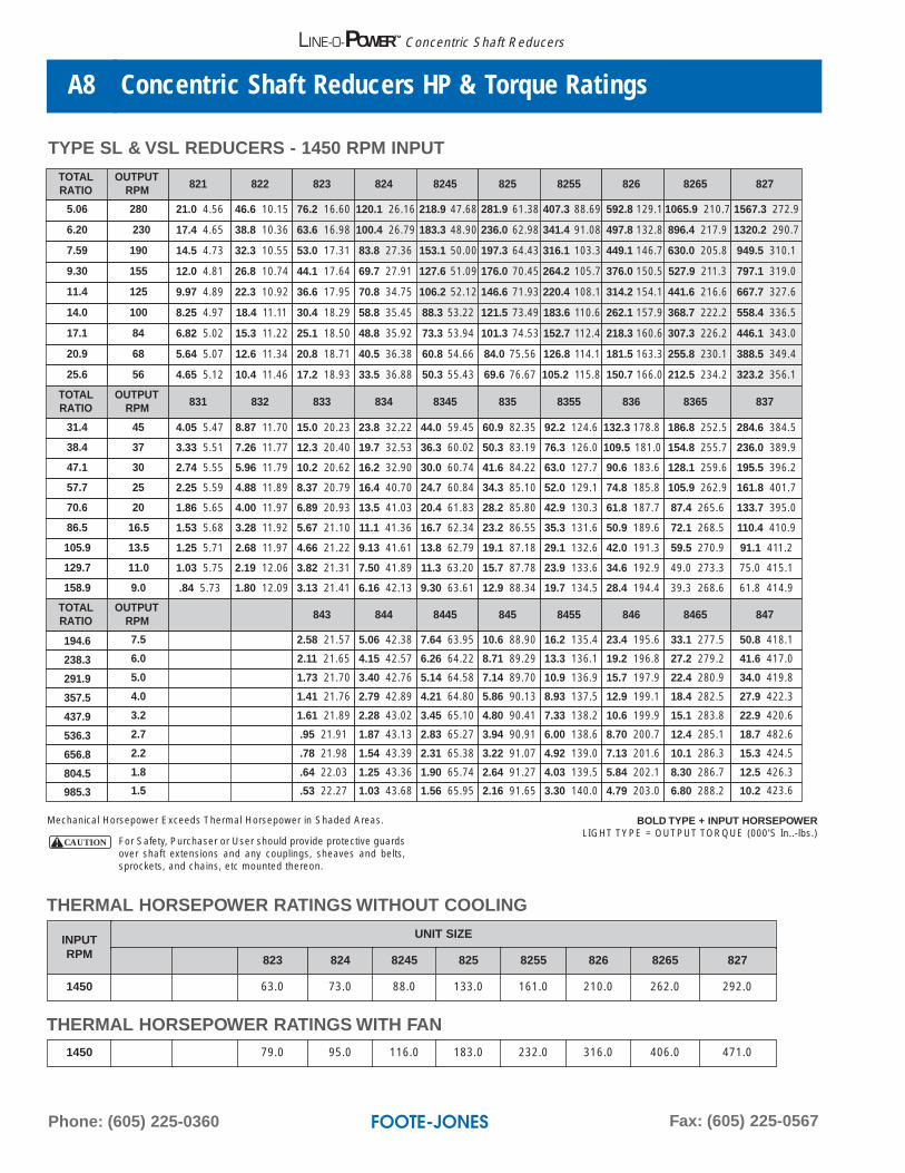
TYPE SL & VSL REDUCERS - 1450 RPM INPUT
TOTALRATIO
OUTPUTRPM 821 822 823 824 8245 825 8255 826 8265 827
5.06 280 21.0 4.56 46.6 10.15 76.2 16.60 120.1 26.16 218.9 47.68 281.9 61.38 407.3 88.69 592.8 129.1 1065.9 210.7 1567.3 272.9
6.20 230 17.4 4.65 38.8 10.36 63.6 16.98 100.4 26.79 183.3 48.90 236.0 62.98 341.4 91.08 497.8 132.8 896.4 217.9 1320.2 290.7
7.59 190 14.5 4.73 32.3 10.55 53.0 17.31 83.8 27.36 153.1 50.00 197.3 64.43 316.1 103.3 449.1 146.7 630.0 205.8 949.5 310.1
9.30 155 12.0 4.81 26.8 10.74 44.1 17.64 69.7 27.91 127.6 51.09 176.0 70.45 264.2 105.7 376.0 150.5 527.9 211.3 797.1 319.0
11.4 125 9.97 4.89 22.3 10.92 36.6 17.95 70.8 34.75 106.2 52.12 146.6 71.93 220.4 108.1 314.2 154.1 441.6 216.6 667.7 327.6
14.0 100 8.25 4.97 18.4 11.11 30.4 18.29 58.8 35.45 88.3 53.22 121.5 73.49 183.6 110.6 262.1 157.9 368.7 222.2 558.4 336.5
17.1 84 6.82 5.02 15.3 11.22 25.1 18.50 48.8 35.92 73.3 53.94 101.3 74.53 152.7 112.4 218.3 160.6 307.3 226.2 446.1 343.0
20.9 68 5.64 5.07 12.6 11.34 20.8 18.71 40.5 36.38 60.8 54.66 84.0 75.56 126.8 114.1 181.5 163.3 255.8 230.1 388.5 349.4
25.6 56 4.65 5.12 10.4 11.46 17.2 18.93 33.5 36.88 50.3 55.43 69.6 76.67 105.2 115.8 150.7 166.0 212.5 234.2 323.2 356.1
TOTALRATIO
OUTPUTRPM 831 832 833 834 8345 835 8355 836 8365 837
31.4 45 4.05 5.47 8.87 11.70 15.0 20.23 23.8 32.22 44.0 59.45 60.9 82.35 92.2 124.6 132.3 178.8 186.8 252.5 284.6 384.5
38.4 37 3.33 5.51 7.26 11.77 12.3 20.40 19.7 32.53 36.3 60.02 50.3 83.19 76.3 126.0 109.5 181.0 154.8 255.7 236.0 389.9
47.1 30 2.74 5.55 5.96 11.79 10.2 20.62 16.2 32.90 30.0 60.74 41.6 84.22 63.0 127.7 90.6 183.6 128.1 259.6 195.5 396.2
57.7 25 2.25 5.59 4.88 11.89 8.37 20.79 16.4 40.70 24.7 60.84 34.3 85.10 52.0 129.1 74.8 185.8 105.9 262.9 161.8 401.7
70.6 20 1.86 5.65 4.00 11.97 6.89 20.93 13.5 41.03 20.4 61.83 28.2 85.80 42.9 130.3 61.8 187.7 87.4 265.6 133.7 395.0
86.5 16.5 1.53 5.68 3.28 11.92 5.67 21.10 11.1 41.36 16.7 62.34 23.2 86.55 35.3 131.6 50.9 189.6 72.1 268.5 110.4 410.9
105.9 13.5 1.25 5.71 2.68 11.97 4.66 21.22 9.13 41.61 13.8 62.79 19.1 87.18 29.1 132.6 42.0 191.3 59.5 270.9 91.1 411.2
129.7 11.0 1.03 5.75 2.19 12.06 3.82 21.31 7.50 41.89 11.3 63.20 15.7 87.78 23.9 133.6 34.6 192.9 49.0 273.3 75.0 415.1
158.9 9.0 .84 5.73 1.80 12.09 3.13 21.41 6.16 42.13 9.30 63.61 12.9 88.34 19.7 134.5 28.4 194.4 39.3 268.6 61.8 414.9
TOTALRATIO
OUTPUTRPM 843 844 8445 845 8455 846 8465 847
194.6 7.5 2.58 21.57 5.06 42.38 7.64 63.95 10.6 88.90 16.2 135.4 23.4 195.6 33.1 277.5 50.8 418.1
238.3 6.0 2.11 21.65 4.15 42.57 6.26 64.22 8.71 89.29 13.3 136.1 19.2 196.8 27.2 279.2 41.6 417.0
291.9 5.0 1.73 21.70 3.40 42.76 5.14 64.58 7.14 89.70 10.9 136.9 15.7 197.9 22.4 280.9 34.0 419.8
357.5 4.0 1.41 21.76 2.79 42.89 4.21 64.80 5.86 90.13 8.93 137.5 12.9 199.1 18.4 282.5 27.9 422.3
437.9 3.2 1.61 21.89 2.28 43.02 3.45 65.10 4.80 90.41 7.33 138.2 10.6 199.9 15.1 283.8 22.9 420.6
536.3 2.7 .95 21.91 1.87 43.13 2.83 65.27 3.94 90.91 6.00 138.6 8.70 200.7 12.4 285.1 18.7 482.6
656.8 2.2 .78 21.98 1.54 43.39 2.31 65.38 3.22 91.07 4.92 139.0 7.13 201.6 10.1 286.3 15.3 424.5
804.5 1.8 .64 22.03 1.25 43.36 1.90 65.74 2.64 91.27 4.03 139.5 5.84 202.1 8.30 286.7 12.5 426.3
985.3 1.5 .53 22.27 1.03 43.68 1.56 65.95 2.16 91.65 3.30 140.0 4.79 203.0 6.80 288.2 10.2 423.6
THERMAL HORSEPOWER RATINGS WITHOUT COOLING
INPUTRPM
UNIT SIZE
823 824 8245 825 8255 826 8265 827
1450 63.0 73.0 88.0 133.0 161.0 210.0 262.0 292.0
THERMAL HORSEPOWER RATINGS WITH FAN1450 79.0 95.0 116.0 183.0 232.0 316.0 406.0 471.0
Mechanical Horsepower Exceeds Thermal Horsepower in Shaded Areas.
For Safety, Purchaser or User should provide protective guardsover shaft extensions and any couplings, sheaves and belts,sprockets, and chains, etc mounted thereon.
CAUTION
BOLD TYPE + INPUT HORSEPOWERLIGHT TYPE = OUTPUT TORQUE (000’S In..-lbs.)

Web: www.footejones.comE-mail: [email protected]
Concentric Shaft Reducers HP & Torque Ratings A9
A
LINE-O-POWER™ Concentric Shaft Reducers
TYPE SL & VSL REDUCERS - 1170 RPM INPUTTOTALRATIO
OUTPUTRPM 821 822 823 824 8245 825 8255 826 8265 827
5.06 230 17.2 4.65 38.4 10.37 62.9 16.98 99.3 26.81 181.3 48.93 233.6 63.04 337.9 91.18 492.7 133.0 814.0 219.7 1035.5 279.5
6.20 190 14.3 4.74 32.0 10.57 52.4 17.33 82.9 27.40 151.5 50.09 195.2 64.55 282.6 93.45 412.9 136.5 686.1 226.9 899.2 297.3
7.59 155 11.9 4.82 26.5 10.75 43.6 17.65 69.0 27.93 126.3 51.12 162.8 65.92 261.5 105.8 372.1 150.6 522.5 211.5 789.0 319.4
9.30 125 9.85 4.89 22.0 10.92 36.2 17.96 57.4 28.45 105.1 52.14 145.1 71.96 218.1 108.2 310.9 154.2 437.0 216.8 660.9 327.8
11.4 100 8.16 4.96 18.2 11.08 30.0 18.25 58.2 35.38 87.4 53.12 120.7 73.35 181.6 110.4 259.3 157.7 364.8 221.8 552.6 336.0
14.0 84 6.75 5.04 15.1 11.26 24.9 18.57 48.3 36.06 72.5 54.14 100.2 74.81 151.1 112.8 215.9 161.2 304.1 227.5 461.2 344.4
17.1 68 5.56 5.08 12.5 11.37 20.6 18.75 40.0 36.48 60.1 54.81 83.1 75.77 125.4 114.4 179.5 163.7 253.0 230.7 384.3 350.5
20.9 56 4.60 5.12 10.3 11.47 17.0 18.95 33.1 36.89 49.8 55.46 68.8 76.71 104.0 116.0 149.1 166.2 210.3 234.4 319.8 356.4
25.6 45 3.79 5.17 8.48 11.58 14.0 19.15 27.4 37.36 41.1 56.17 56.9 77.74 86.1 117.6 123.6 168.8 174.4 238.2 260.5 366.4
TOTALRATIO
OUTPUTRPM 831 832 833 834 8345 835 8355 836 8365 837
31.4 37 3.29 5.51 7.19 11.81 12.2 20.45 19.5 32.59 35.9 60.18 49.8 83.41 75.4 126.3 108.4 181.5 153.1 256.4 233.5 391.0
38.4 30 2.71 5.54 5.86 11.77 10.1 20.58 16.1 32.87 29.6 60.69 41.1 84.17 62.3 127.6 89.6 183.5 126.7 259.4 193.3 396.0
47.1 25 2.22 5.61 4.82 11.87 8.27 20.78 13.2 33.21 24.4 61.37 33.9 85.12 51.4 129.2 74.0 185.9 104.7 263.0 160.0 401.8
57.7 20 1.83 5.63 3.97 11.97 6.81 20.95 13.3 41.06 20.1 61.92 27.9 85.91 42.4 130.5 61.1 188.0 86.5 266.1 132.2 406.9
70.6 16.5 1.51 5.67 3.23 11.94 5.60 21.07 11.0 41.34 16.6 62.37 23.0 86.56 34.9 131.6 50.4 189.7 71.3 268.5 109.2 411.0
86.5 13.5 1.23 5.69 2.66 12.02 4.60 21.20 9.03 41.66 13.6 62.86 18.9 87.23 28.8 132.7 41.5 191.4 58.8 271.2 91.1 411.6
105.9 11.0 1.01 5.71 2.17 12.04 3.77 21.34 7.41 41.93 11.2 63.21 15.5 87.79 23.7 133.7 34.2 192.9 48.4 273.4 75.0 415.2
129.7 9.0 .83 5.73 1.78 12.09 3.10 21.45 6.09 42.13 9.19 63.58 12.8 88.38 19.5 134.6 28.1 194.4 39.8 275.6 61.2 414.9
158.9 7.5 .68 5.74 1.45 12.16 2.55 21.57 5.00 42.37 7.55 63.94 10.5 88.93 16.0 135.4 23.1 195.8 32.8 277.6 50.4 418.3
TOTALRATIO
OUTPUTRPM 843 844 8445 845 8455 846 8465 847
194.6 6.0 2.08 21.59 4.10 42.56 6.19 64.26 8.61 89.31 13.1 136.2 19.0 197.0 30.0 310.8 41.5 417.2
238.3 5.0 1.70 21.69 3.39 42.75 5.08 64.57 7.06 89.73 10.8 136.8 15.6 198.1 22.1 281.0 34.1 419.9
291.9 4.0 1.40 21.87 2.75 42.93 4.16 64.78 5.79 90.10 8.84 137.6 12.8 199.1 18.2 282.6 28.0 422.5
357.5 3.3 1.15 21.95 2.26 43.14 3.41 65.09 4.75 90.51 7.24 138.1 10.5 200.0 14.9 283.9 22.8 420.8
437.9 2.7 .94 21.94 1.85 43.17 2.80 65.34 3.89 90.82 5.94 138.7 8.60 200.7 12.2 285.2 18.7 422.7
536.3 2.2 .77 21.96 1.51 43.33 2.29 65.58 3.18 91.00 4.87 139.3 7.05 201.7 10.0 286.3 15.3 424.7
656.8 1.8 .63 21.94 1.24 43.52 1.87 65.81 2.61 91.28 3.98 139.4 5.78 202.4 8.20 287.3 12.6 426.3
804.5 1.5 .52 22.09 1.01 43.77 1.53 65.87 2.13 91.44 3.26 140.0 4.73 202.8 6.72 288.2 10.3 427.7
985.3 1.2 .42 22.29 .83 43.52 1.30 68.47 1.75 91.82 2.73 139.1 3.87 203.3 5.51 289.3 8.4 429.4
THERMAL HORSEPOWER RATINGS WITHOUT COOLING
INPUTRPM
UNIT SIZE
824 8245 825 8255 826 8265 827
1170 80.0 102.0 157.0 193.0 257.0 322.0 365.0
THERMAL HORSEPOWER RATINGS WITH FAN1170 106.0 125.0 203.0 260.0 357.0 467.0 547.0
Mechanical Horsepower Exceeds Thermal Horsepower in Shaded Areas.
For Safety, Purchaser or User should provide protective guardsover shaft extensions and any couplings, sheaves and belts,sprockets, and chains, etc mounted thereon.
CAUTION
BOLD TYPE + INPUT HORSEPOWERLIGHT TYPE = OUTPUT TORQUE (000’S In..-lbs.)

Phone: (605) 225-0360 Fax: (605) 225-0567
Concentric Shaft Reducers HP & Torque RatingsA10
LINE-O-POWER™ Concentric Shaft Reducers
TYPE SL & VSL REDUCERS - 870 RPM INPUT
TOTALRATIO
OUTPUTRPM 821 822 823 824 8245 825 8255 826 8265 827
5.06 172 13.2 4.77 29.3 10.65 48.2 17.47 76.2 27.64 139.3 50.55 179.6 65.17 260.1 94.40 380.3 138.0 626.8 227.5 789.4 286.5
6.20 138 10.9 4.85 24.4 10.83 40.0 17.80 63.4 28.18 116.1 51.61 149.7 66.57 217.0 96.50 317.8 141.3 536.9 238.8 684.7 304.5
7.59 115 9.03 4.92 20.2 11.00 33.2 18.08 52.7 28.67 96.6 52.56 124.6 67.82 200.5 109.2 286.0 155.7 402.2 219.0 608.7 331.4
9.30 94 7.47 4.99 16.7 11.14 27.5 18.36 43.7 29.14 80.2 53.49 110.8 73.89 166.9 111.3 238.4 159.0 335.5 223.8 508.5 339.2
11.4 77 6.17 5.05 13.8 11.30 22.8 18.62 44.3 36.20 66.5 54.37 91.9 75.15 138.7 113.4 198.3 162.2 279.4 228.5 424.1 346.7
14.0 62 5.10 5.12 11.4 11.46 18.8 18.92 36.7 36.82 55.1 55.31 76.2 76.50 115.1 115.6 164.8 165.5 232.3 233.3 353.1 345.6
17.1 51 4.20 5.15 9.41 11.55 15.6 19.08 30.3 37.18 45.6 55.89 63.1 77.34 95.3 116.9 136.7 167.7 192.9 236.6 293.5 360.0
20.9 42 3.46 5.19 7.77 11.64 12.8 19.24 25.1 37.55 37.7 56.47 52.2 78.17 78.9 118.3 113.3 169.9 160.0 239.8 243.7 365.3
25.6 34 2.85 5.23 6.39 11.74 10.6 19.42 20.7 37.94 31.1 57.10 43.1 79.08 65.3 119.8 93.8 172.2 132.5 243.2 202.0 370.9
TOTALRATIO
OUTPUTRPM 831 832 833 834 8345 835 8355 836 8365 837
31.4 28 2.48 5.57 5.38 11.83 9.20 20.72 14.7 33.05 27.1 61.10 37.6 84.71 57.1 128.5 82.1 184.9 116.1 261.4 177.3 399.2
38.4 23 2.04 5.62 4.40 11.91 7.57 20.84 12.1 33.30 22.3 61.53 31.0 85.37 47.1 129.6 67.8 186.6 95.9 264.1 146.5 403.6
47.1 18.5 1.68 5.66 3.61 11.89 6.22 21.02 10.0 33.61 18.4 62.15 25.5 86.22 38.8 131.0 55.9 188.8 79.1 267.3 121.0 408.9
57.7 15.0 1.37 5.69 2.95 12.00 5.11 21.15 10.0 41.51 15.1 62.62 21.0 86.94 32.0 132.2 46.1 190.7 65.3 270.0 101.3 409.6
70.6 12.3 1.13 5.73 2.42 12.02 4.20 21.28 8.25 41.79 12.4 63.01 17.3 87.51 26.3 133.1 37.9 192.1 53.8 272.8 83.1 413.3
86.5 10.0 .93 5.77 1.98 12.09 3.44 21.37 6.78 42.05 10.2 63.42 14.2 88.10 21.6 134.1 31.2 193.7 44.3 274.5 68.2 413.3
105.9 8.2 .76 5.75 1.62 12.05 2.83 21.48 5.57 42.27 8.39 63.75 11.7 88.61 17.8 135.0 25.7 195.0 36.4 276.5 56.9 416.5
129.7 6.7 .63 5.83 1.32 12.03 2.32 21.61 4.57 42.47 6.89 64.08 9.58 89.07 14.6 135.8 21.1 196.3 29.9 278.4 45.8 415.7
158.9 5.5 .51 5.76 1.09 12.07 1.90 21.64 3.75 42.71 5.66 64.46 7.86 89.56 12.0 136.5 17.3 197.5 24.6 280.2 37.5 418.5
TOTALRATIO
OUTPUTRPM 843 844 8445 845 8455 846 8465 847
194.6 4.5 1.56 21.71 3.07 42.86 4.64 64.71 6.44 89.94 9.83 137.2 14.2 198.5 20.2 281.2 31.1 421.1
238.3 3.7 1.27 21.75 2.52 43.00 3.80 64.91 5.28 90.29 8.06 137.8 11.7 199.4 16.6 283.1 25.4 423.3
291.9 3.0 1.06 21.99 2.06 43.14 3.11 65.13 4.33 90.72 6.61 138.3 9.58 200.5 13.6 284.4 20.8 421.7
357.5 2.4 .86 22.01 1.69 43.25 2.56 65.52 3.55 90.90 5.07 138.8 7.85 201.2 11.1 285.7 17.0 423.4
437.9 2.0 .70 21.89 1.38 43.46 2.09 65.67 2.91 91.36 4.15 139.3 6.43 202.1 9.13 286.8 13.9 425.1
536.3 1.6 .58 22.15 1.13 43.51 1.71 65.66 2.37 91.30 3.40 139.9 5.26 202.4 7.48 287.9 11.4 427.0
656.8 1.3 .47 21.89 .93 43.77 1.40 66.14 1.95 91.83 2.79 138.9 4.30 203.2 6.13 288.9 9.33 424.0
804.5 1.1 .38 22.15 .76 43.71 1.14 65.86 1.60 92.08 2.49 139.3 3.54 204.0 5.02 289.7 7.62 425.5
985.3 .88 .31 22.13 .62 43.54 .94 66.38 1.30 92.08 2.03 139.2 2.89 204.1 4.11 290.5 6.23 427.6
THERMAL HORSEPOWER RATINGS WITHOUT COOLING
INPUTRPM
UNIT SIZE
8245 825 8255 826 8265 827
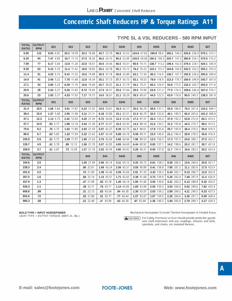
870 115.0 181.0 226.0 303.0 382.0 440.0
THERMAL HORSEPOWER RATINGS WITH FAN
870 140.0 217.0 280.0 392.0 515.0 611.0
Mechanical Horsepower Exceeds Thermal Horsepower in Shaded Areas.
For Safety, Purchaser or User should provide protective guardsover shaft extensions and any couplings, sheaves and belts,sprockets, and chains, etc mounted thereon.
CAUTION
BOLD TYPE + INPUT HORSEPOWERLIGHT TYPE = OUTPUT TORQUE (000’S In..-lbs.)
Web: www.footejones.comE-mail: [email protected]
Concentric Shaft Reducers HP & Torque Ratings A11
A
LINE-O-POWER™ Concentric Shaft Reducers
TYPE SL & VSL REDUCERS - 580 RPM INPUTTOTALRATIO
OUTPUTRPM 821 822 823 824 8245 825 8255 826 8265 827
5.06 115 9.03 4.92 20.2 10.99 33.2 18.08 43.7 23.79 96.5 52.55 124.6 67.82 180.8 98.4 265.1 144.3 433.6 236.0 575.1 313.1
6.20 94 7.47 4.99 16.7 11.14 27.5 18.36 36.2 24.15 80.2 53.49 103.5 69.06 150.3 100.3 220.7 147.2 380.9 254.1 472.5 315.2
7.59 77 6.17 5.04 13.8 11.28 22.8 18.61 30.0 24.46 66.5 54.31 85.9 70.15 138.7 113.2 198.4 162.0 279.4 228.1 424.1 345.9
9.30 63 5.10 5.10 11.4 11.42 18.8 18.85 25.1 24.78 55.1 55.12 76.2 76.23 115.1 115.1 164.8 164.9 232.3 232.5 353.1 353.3
11.4 51 4.20 5.15 9.41 11.55 15.6 19.08 30.3 37.18 45.6 55.89 63.1 77.34 95.3 116.9 136.7 167.7 192.9 236.6 293.5 360.0
14.0 41 3.46 5.22 7.76 11.68 12.8 19.34 25.1 37.73 37.7 56.73 52.1 78.53 78.9 118.9 113.3 170.7 160.0 240.9 243.7 367.0
17.1 34 2.85 5.24 6.39 11.76 10.6 19.46 20.7 38.02 31.1 57.19 43.1 79.21 65.2 120.9 93.8 172.5 132.4 243.7 202.0 371.6
20.9 28 2.34 5.27 5.26 11.83 8.72 19.60 17.0 38.31 25.6 57.66 35.5 79.90 53.9 121.2 77.5 174.3 109.6 246.4 167.3 376.1
25.6 23 1.93 5.31 4.33 11.93 7.17 19.75 14.0 38.67 21.1 58.20 29.3 80.67 44.5 122.5 63.9 176.0 90.5 249.3 138.3 381.0
TOTALRATIO
OUTPUTRPM 831 832 833 834 8345 835 8355 836 8365 837
31.4 18.5 1.68 5.66 3.61 11.87 6.22 21.02 10.0 33.61 18.4 62.17 25.5 86.29 38.8 131.1 55.9 188.9 79.2 267.4 123.2 409.1
38.4 15.0 1.37 5.68 2.95 11.98 5.11 21.11 8.18 33.80 15.1 62.51 21.0 86.79 32.0 132.0 46.1 190.3 65.3 265.6 101.3 408.9
47.1 12.3 1.13 5.73 2.42 12.03 4.20 21.29 6.72 34.04 12.4 63.06 17.3 87.57 26.3 133.3 37.9 192.2 53.8 272.4 83.1 413.5
57.7 10.0 .93 5.77 1.98 12.10 3.44 21.38 6.77 42.07 10.2 63.45 14.2 88.16 21.6 134.2 31.2 193.8 44.3 274.7 68.2 413.5
70.6 8.2 .76 5.75 1.62 11.89 2.83 21.50 5.57 42.27 8.39 63.75 11.7 88.61 17.8 135.0 25.7 195.0 36.4 276.5 55.9 416.5
86.5 6.7 .63 5.83 1.32 11.94 2.32 21.62 4.57 42.49 6.89 64.10 9.58 89.11 15.0 140.0 21.1 196.4 29.9 278.5 45.8 416.4
105.9 5.5 .51 5.75 1.09 11.97 1.90 21.63 3.75 42.69 5.66 64.44 7.86 89.53 12.0 136.5 17.3 197.5 24.6 280.1 37.5 422.2
129.7 4.5 .41 5.78 .89 12.12 1.56 21.70 3.07 42.85 4.65 64.69 6.44 89.92 9.83 137.1 14.2 198.4 20.2 281.7 30.7 421.0
158.9 3.7 .31 5.87 .72 12.09 1.27 21.76 2.52 42.99 3.80 64.92 5.28 90.31 8.06 137.8 11.7 199.4 16.6 283.2 25.2 423.4
TOTALRATIO
OUTPUTRPM 843 844 8445 845 8455 846 8465 847
194.6 3.0 1.05 21.99 2.06 43.14 3.11 65.13 4.33 90.72 6.61 138.3 9.58 200.5 13.6 284.6 20.8 421.7
238.3 2.4 .86 22.01 1.69 43.24 2.56 65.51 3.55 90.89 5.41 138.8 7.85 201.2 11.1 285.6 17.0 423.4
291.9 2.0 .70 21.89 1.38 43.40 2.09 65.66 2.91 91.35 4.43 139.3 6.43 202.1 9.13 286.7 13.9 425.0
357.5 1.6 .58 22.14 1.13 43.51 1.71 65.65 2.38 91.68 3.73 139.9 5.26 202.4 7.48 287.9 11.4 426.9
437.9 1.3 .47 21.89 .93 43.78 1.40 66.14 1.95 91.84 3.05 139.0 4.31 203.2 6.13 288.8 9.32 424.5
536.3 1.1 .38 22.11 .76 43.71 1.14 65.85 1.60 92.08 2.50 139.3 3.54 204.0 5.02 289.6 7.62 425.4
656.8 .89 .31 22.13 .62 43.54 .94 66.38 1.30 92.07 2.03 139.2 2.89 204.2 4.11 290.5 6.23 427.5
804.5 .72 .25 21.86 .51 43.71 .77 66.44 1.07 92.67 1.67 139.9 2.36 204.6 3.36 291.1 5.09 428.4
985.3 .59 .21 22.48 .41 43.90 .63 66.38 .87 92.08 1.36 140.3 1.94 205.6 2.79 289.1 4.17 429.3
Mechanical Horsepower Exceeds Thermal Horsepower in Shaded Areas.
For Safety, Purchaser or User should provide protective guardsover shaft extensions and any couplings, sheaves and belts,sprockets, and chains, etc mounted thereon.
CAUTION
BOLD TYPE + INPUT HORSEPOWERLIGHT TYPE = OUTPUT TORQUE (000’S In..-lbs.)
Phone: (605) 225-0360 Fax: (605) 225-0567
Tables of Actual RatiosA12
LINE-O-POWER™ Concentric Shaft Reducers
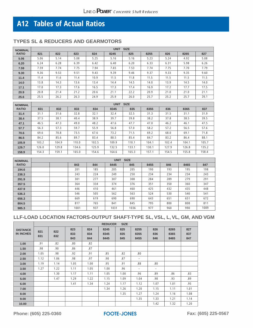
TYPES SL & REDUCERS AND GEARMOTORS
NOMINALRATIO
UNIT SIZE
831 832 833 834 8345 835 8355 836 8365 837
31.4 31.1 31.6 32.8 32.1 32.4 32.5 31.3 31.5 31.1 31.9
38.4 37.5 38.1 40.4 38.9 39.7 39.8 38.2 37.8 38.5 39.5
47.1 46.5 47.3 49.0 48.2 47.6 47.7 47.0 46.2 46.1 47.5
57.7 56.3 57.3 59.7 55.9 56.8 57.0 58.2 57.2 56.5 57.6
70.6 69.6 70.8 73.5 67.6 73.2 71.5 69.2 68.0 69.1 71.8
86.5 84.2 85.6 89.7 83.4 88.5 85.4 84.7 83.2 86.4 88.1
105.9 103.2 104.9 110.0 102.5 109.9 110.1 104.1 102.4 104.1 105.7
129.7 126.0 129.8 134.6 125.9 132.5 133.1 130.1 127.9 126.8 135.2
158.9 154.3 159.1 165.0 154.6 164.6 165.3 157.1 154.5 155.8 158.4
NOMINALRATIO
UNIT SIZE
843 844 8445 845 8455 846 8465 847
194.6 201 185 205 205 190 193 195 198
238.3 243 224 249 250 234 234 234 243
291.9 301 277 307 308 284 289 279 291
357.5 364 334 374 376 351 350 360 347
437.9 446 410 461 460 425 432 435 448
536.3 546 505 562 563 524 530 540 541
656.3 669 619 690 690 643 651 651 672
804.5 817 765 841 845 795 800 808 811
985.3 1001 937 1031 1036 977 960 990 1009
NOMINALRATIO
UNIT SIZE
821 822 823 824 8245 825 8255 826 8265 827
5.06 5.06 5.14 5.08 5.25 5.16 5.16 5.23 5.24 4.92 5.08
6.20 6.24 6.28 6.39 6.42 6.40 6.20 6.33 6.31 5.98 6.26
7.59 7.59 7.74 7.75 7.94 7.65 7.53 7.74 7.75 7.70 7.79
9.30 9.36 9.53 9.51 9.43 9.39 9.46 9.37 9.33 9.35 9.60
11.4 11.4 11.6 11.4 10.9 11.5 11.8 11.5 11.5 11.5 11.5
14.0 13.8 14.3 13.6 13.4 14.4 14.5 14.0 13.9 14.5 14.0
17.1 17.0 17.3 17.6 16.5 17.3 17.4 16.9 17.2 17.7 17.5
20.9 20.8 21.4 21.2 20.6 21.1 22.2 20.9 21.0 21.0 21.1
25.6 25.5 26.2 26.3 24.9 25.9 26.0 25.7 25.2 25.7 26.1
DISTANCEIN INCHES
REDUCER SIZE
821
831
822
832
823
833
843
824
834
844
8245
8345
8445
825
835
845
8255
8355
8455
826
836
846
8265
8365
8465
827
837
847
1.00 .91 .82 .80 .82
1.50 .98 .90 .86 .87
2.00 1.05 .98 .92 .91 .85 .82 .80
2.50 1.12 1.06 .98 .97 .90 .87 –
3.00 1.19 1.14 1.05 1.00 .95 .91 .88 .80
3.50 1.27 1.22 1.11 1.05 1.00 .96 – –
4.00 1.30 1.17 1.11 1.05 1.00 .96 .89 .86 .83
5.00 1.47 1.29 1.22 1.15 1.09 1.04 .98 .93 .89
6.00 1.41 1.34 1.24 1.17 1.12 1.07 1.01 .95
7.00 1.34 1.26 1.20 1.15 1.11 1.01
8.00 1.35 1.27 1.24 1.16 1.08
9.00 1.35 1.33 1.21 1.14
10.00 1.42 1.32 1.20
LLF-LOAD LOCATION FACTORS-OUTPUT SHAFT-TYPE SL, VSL, L, VL, GM, AND VGM

Web: www.footejones.comE-mail: [email protected]
Overhung Load Capacities ◆ In Pounds – Output Shaft A13
A
LINE-O-POWER™ Concentric Shaft Reducers
◆ Capacities are for radial loads only, with load location at one shaft diameter distance from shaft seal.If radial and thrust loads are applied simultaneously, consult factory.
Nominal
Output
Speed
REDUCER SIZE
821
831
822
832
823
833
843
824
834
844
8245
8345
8445
825
835
845
8255
8355
8455
826
836
846
8265
8365
8465
827
837
847
350 2093 2728 4058 5632 7108 6915 12573 11384 9888 13703
280 2249 2932 4433 6035 7687 7412 13447 12190 10738 14390
230 2405 3160 4773 6497 8204 7977 14336 13170 12607 16363
190 2582 3404 5161 6894 8835 8368 15336 14102 13596 17780
155 2757 3648 5527 7035 9507 9114 16496 15245 14752 19106
125 2757 3934 5912 7557 10305 9864 17679 16349 16147 20669
100 2757 4051 6323 8126 11079 10579 18871 17673 17421 22570
84 2757 4051 6323 8370 11692 11697 20353 19016 18635 24318
68 2757 4051 6323 8370 11692 12345 21924 20327 20145 26475
56 2757 4051 6323 8370 11692 13168 21924 21681 21179 27898
45 2757 4051 6323 8370 11692 14235 21924 23182 23032 30393
37 2757 4051 6323 8370 11692 15237 21924 24947 24682 32681
30 2757 4051 6323 8370 11692 16287 21924 26957 26689 35264
25 2757 4051 6323 8370 11692 16534 21924 28686 28819 38414
20 2757 4051 6323 8370 11692 16534 21924 29157 31340 41566
16.5 2757 4051 6323 8370 11692 16534 21924 29157 33597 44550
13.5 2757 4051 6323 8370 11692 16534 21924 29157 36144 48886
11 & Lower 2757 4051 6323 8370 11692 16534 21924 29157 36756 51514
OUTPUT SHAFT OVERHUNG LOAD CAPACITY AT NOMINAL OUTPUT SPEEDS
Phone: (605) 225-0360 Fax: (605) 225-0567
Overhung Load Capacities ◆ In Pounds – Input ShaftA14
LINE-O-POWER™ Concentric Shaft Reducers
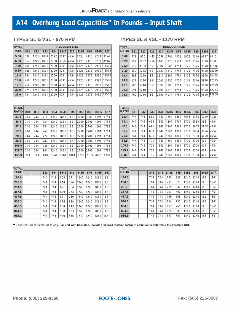
TOTALRATIO
REDUCER SIZE
821 822 823 824 8245 825 8255 826 8265 827
5.06 479 950 1443 2099 2902 4053 5002 7376 6697 6715
6.20 552 1062 1756 2403 3375 4524 5377 7376 7390 6658
7.59 612 1158 1861 2584 3585 4754 6125 7376 9990 11516
9.30 650 1228 1861 2627 3817 4754 6125 7376 9990 12040
11.4 665 1240 1861 2617 3892 4754 6125 7376 9990 12405
14.0 677 1240 1861 2663 3950 4754 6125 7376 9990 12575
17.1 686 1240 1861 2697 3988 4754 6125 7376 9990 12699
20.9 694 1240 1861 2700 4018 4754 6125 7376 9990 12783
25.6 700 1240 1861 2700 4074 4754 6125 7376 9990 12860
TYPES SL & VSL - 1170 RPMTYPES SL & VSL - 870 RPM
TOTALRATIO 831 832 833 834 8345 835 8355 836 8365 837
31.4 744 744 615 1240 1861 1462 2654 1735 3719 4038
38.4 744 744 654 1240 1861 1707 2700 2533 3831 4754
47.1 744 744 671 1240 1861 1861 2700 2603 3908 4751
57.7 744 744 683 1240 1861 1861 2700 2664 3994 4754
70.6 744 744 691 1240 1861 1861 2700 2700 4050 4754
86.5 744 744 701 1240 1861 1861 2700 2700 4091 4754
105.9 744 744 706 1240 1861 1861 2700 2700 4091 4754
129.7 744 744 762 1240 1861 1861 2700 2700 4091 4754
158.9 744 744 766 1240 1861 1861 2700 2700 4091 4754
TOTALRATIO 843 844 8445 845 8455 846 8465 847
194.6 744 744 723 660 1240 1240 1861 1861
238.3 744 744 732 673 1240 1240 1861 1861
291.9 744 744 739 682 1240 1240 1861 1861
357.5 744 744 747 692 1240 1240 1861 1861
437.9 744 744 789 699 1240 1240 1861 1861
536.3 744 744 794 757 1240 1240 1861 1861
656.3 744 744 822 761 1240 1240 1861 1861
804.5 744 744 825 801 1240 1240 1861 1861
985.3 744 744 827 803 1240 1240 1861 1861
TOTALRATIO
REDUCER SIZE
821 822 823 824 8245 825 8255 826 8265 827
5.06 590 1153 1840 2592 3637 4754 6033 7376 8204 9124
6.20 667 1240 1861 2700 3965 4754 6125 7376 8733 8916
7.59 708 1240 1861 2700 4091 4754 6125 7376 9990 13319
9.30 728 1240 1861 2700 4091 4754 6125 7376 9990 13502
11.4 744 1240 1861 2700 4091 4754 6125 7376 9990 13502
14.0 756 1240 1861 2700 4091 4754 6125 7376 9990 13502
17.1 766 1240 1861 2700 4091 4754 6125 7376 9990 13502
20.9 775 1240 1861 2700 4091 4754 6125 7376 9990 13502
25.6 781 1240 1861 2700 4091 4754 6125 7376 9990 13502
TOTALRATIO 831 832 833 834 8345 835 8355 836 8365 837
31.4 744 744 714 1240 1861 1861 2700 2281 4091 4754
38.4 744 744 734 1240 1861 1861 2700 2700 4091 4754
47.1 744 744 751 1240 1861 1861 2700 2700 4091 4754
57.7 744 744 763 1240 1861 1861 2700 2700 4091 4754
70.6 744 744 772 1240 1861 1861 2700 2700 4091 4754
86.5 744 744 782 1240 1861 1861 2700 2700 4091 4754
105.9 744 744 788 1240 1861 1861 2700 2700 4091 4754
129.7 744 744 844 1240 1861 1861 2700 2700 4091 4754
158.9 744 744 848 1240 1861 1861 2700 2700 4091 4754
TOTALRATIO 843 844 8445 845 8455 846 8465 847
194.6 744 744 805 741 1240 1240 1861 1861
238.3 744 744 814 754 1240 1240 1861 1861
291.9 744 744 821 764 1240 1240 1861 1861
357.5 744 744 829 774 1240 1240 1861 1861
437.9 744 744 871 780 1240 1240 1861 1861
536.3 744 744 876 839 1240 1240 1861 1861
656.3 744 744 904 843 1240 1240 1861 1861
804.5 744 744 908 883 1240 1240 1861 1861
985.3 744 744 910 886 1240 1240 1861 1861
◆ Capacities are for radial loads only. For unit with backstop, include 1.10 load location factor in equation to determine the effective OHL.

Web: www.footejones.comE-mail: [email protected]
Overhung Load Capacities ◆ In Pounds – Input Shaft A15
A
LINE-O-POWER™ Concentric Shaft Reducers
TYPES SL & VSL - 1750 RPMTYPES SL & VSL - 1450 RPM
TOTALRATIO
REDUCER SIZE
821 822 823 824 8245 825 8255 826 8265 827
5.06 350 715 992 1538 2070 3059 3828 6067 4622 3153
6.20 350 818 1291 1811 2601 3479 4151 6446 5916 2940
7.59 350 905 1495 2049 2878 3848 5895 7376 9990 9433
9.30 418 968 1591 2206 3087 4366 6125 7376 9990 9878
11.4 473 1023 1675 2141 3227 4452 6125 7376 9990 10185
14.0 521 1071 1704 2312 3350 4515 6125 7376 9990 10451
17.1 559 1113 1727 2344 3485 4565 6125 7376 9990 10677
20.9 581 1175 1742 2369 3511 4623 6125 7376 9990 10819
25.6 590 1159 1755 2432 3567 4637 6125 7376 9990 10937
TOTALRATIO
REDUCER SIZE
821 822 823 824 8245 825 8255 826 8265 827
5.06 407 819 1191 1785 2435 3497 4345 6773 5837 5068
6.20 478 926 1503 2073 2994 3941 4693 7183 6558 4985
7.59 535 1018 1665 2323 3192 4331 6125 7376 9990 10356
9.30 585 1084 1764 2436 3412 4663 6125 7376 9990 10838
11.4 613 1141 1800 2426 3561 4752 6125 7376 9990 11172
14.0 624 1192 1823 2470 3668 4754 6125 7376 9990 11465
17.1 633 1236 1847 2503 3710 4754 6125 7376 9990 11717
20.9 641 1240 1861 2528 3737 4754 6125 7376 9990 11878
25.6 647 1240 1861 2589 3795 4754 6125 7376 9990 11989
TOTALRATIO 831 832 833 834 8345 835 8355 836 8365 837
31.4 597 647 466 1162 1704 932 2300 1097 3006 2891
38.4 603 657 518 1215 1738 1163 2356 1875 3317 4283
47.1 736 668 562 1240 1767 1349 2449 2168 3390 4384
57.7 740 676 585 1240 1786 1486 2489 2307 3472 4474
70.6 744 683 593 1240 1805 1692 2515 2345 3525 4561
86.5 744 689 602 1240 1819 1717 2547 2390 3572 4621
105.9 744 693 607 1240 1831 1694 2567 2419 3604 4678
129.7 744 728 662 1240 1861 1842 2580 2439 3624 4712
158.9 744 731 666 1240 1861 1853 2595 2460 3650 4745
TOTALRATIO 831 832 833 834 8345 835 8355 836 8365 837
31.4 744 693 533 1240 1824 1168 2460 1381 3439 3401
38.4 744 703 587 1240 1859 1406 2517 2174 3548 4585
47.1 744 714 617 1240 1861 1598 2611 2409 3623 4689
57.7 744 722 629 1240 1861 1738 2652 2468 3708 4754
70.6 744 729 637 1240 1861 1807 2679 2507 3762 4754
86.5 744 735 646 1240 1861 1833 2700 2553 3810 4754
105.9 744 740 652 1240 1861 1826 2700 2583 3842 4754
129.7 744 744 707 1240 1861 1861 2700 2603 3864 4754
158.9 744 744 711 1240 1861 1861 2700 2624 3890 4754
TOTALRATIO 843 844 8445 845 8455 846 8465 847
194.6 744 689 623 519 1240 1191 1765 1586
238.3 744 695 633 556 1240 1240 1794 1678
291.9 744 701 640 583 1240 1240 1813 1714
357.5 744 706 647 593 1240 1240 1832 1739
437.9 744 710 688 599 1240 1240 1847 1763
536.3 744 739 693 657 1240 1240 1858 1782
656.3 744 741 721 661 1240 1240 1861 1797
804.5 744 744 724 700 1240 1240 1861 1861
985.3 744 744 726 703 1240 1240 1861 1861
TOTALRATIO 843 844 8445 845 8455 846 8465 847
194.6 744 735 668 590 1240 1240 1861 1759
238.3 744 742 678 618 1240 1240 1861 1802
291.9 744 744 685 628 1240 1240 1861 1838
357.5 744 744 692 638 1240 1240 1861 1861
437.9 744 744 734 644 1240 1240 1861 1861
536.3 744 744 739 702 1240 1240 1861 1861
656.3 744 744 766 706 1240 1240 1861 1861
804.5 744 744 770 745 1240 1240 1861 1861
985.3 744 744 772 748 1240 1240 1861 1861
◆ Capacities are for radial loads only. For unit with backstop, include 1.10 load location factor in equation to determine the effective OHL.

Phone: (605) 225-0360 Fax: (605) 225-0567
Gear Reducer DimensionsA16
LINE-O-POWER™ Concentric Shaft Reducers
C
R
N
U
GK
L
V
EH
AE
J
O
D
F
B
XU
XN
XV Foote-Jones
XU
KN
KV
KC
TYPE SL TYPE KSL
DOUBLE REDUCTION
TYPE VSL TYPE HSL
VF
VH-HOLESVF
VH-HOLES
VT
VJ
VB
VRVG
VEVL
VC
VA
U
LUBE PUMPFURNISHED
ON VERTICALUNITS ONLY
CC
*
CMTYPE CLM C
LD
GAP
LCTYPE L
UNITSIZE
CM
CC
ADAPTER&
COUPLINGWEIGHT
143TC-
145TC
182TC-
256TC
284TC-
286TC
324TC-
326TC
821 21.00 21.00 - - 16.64 55
822 23.43 24.83 - - 20.60 65
823 26.63 28.03 28.88 29.08 23.37 85
824 - 32.60 33.45 33.65 27.25 90
UNITSIZE
MOTORFRAME LD ➁
821 213-5T 6.50
822 254-6T 7.25
823 324-6T 9.25
824 364-5T 10.50
8245 404-5T 11.75
*The 821-256TC requires RiserBlocks to equal 7.25” dimensions
Available in the same MotorFrame sizes as Type L Units.
Fig. I4 Mounting HolesEqually Spaced
Fig. II6 Mounting HolesEqually Spaced
Reducer with Backstop

Web: www.footejones.comE-mail: [email protected]
Gear Reducer Dimensions A17
A
LINE-O-POWER™ Concentric Shaft Reducers
TYPES SL DIMENSIONS
DOUBLE REDUCTION
UNITSIZE
A B C KC D E F G H J K L N O R UNITWEIGHT
821 11.38 11.50 16.65 18.06 5.75 4.25 10.00 0.62 0.69 2.50 1.38 1.25 2.88 11.44 12.31 100
822 12.50 12.50 20.62 22.38 6.25 4.50 11.00 0.75 0.69 3.25 1.50 1.25 3.88 11.94 14.75 140
823 15.25 15.00 23.38 24.93 8.00 5.50 12.50 1.00 0.94 4.00 2.12 1.88 4.50 15.25 16.00 280
824 18.50 18.00 27.25 28.63 9.25 7.00 15.50 1.25 1.06 4.25 2.25 1.75 5.88 18.50 20.56 520
8245 20.50 20.00 31.38 32.88 10.50 7.75 17.00 1.50 1.19 5.00 3.50 2.00 6.38 20.25 23.00 600
825 22.75 21.75 33.62 35.12 11.50 8.62 18.75 1.50 1.31 5.50 3.50 2.00 6.88 22.88 24.62 850
8255 26.00 26.00 41.00 42.80 13.25 10.00 22.00 1.75 1.56 6.00 3.50 2.50 7.88 25.25 29.50 1150
826 31.00 25.50 42.12 43.87 15.75 12.50 22.00 2.00 1.56 6.00 5.75 3.00 8.62 29.75 29.25 1700
8265 35.50 27.00 47.00 49.25 18.75 16.25 24.00 1.50 1.56 6.00 6.00 1.70 9.68 34.75 33.88 2300827 40.00 31.50 54.00 56.25 21.75 17.50 28.00 1.75 1.81 6.00 7.00 2.00 10.38 40.00 38.25 3100
UNITSIZE
OUTPUT SHAFTINPUT SHAFT
BACKSTOPWEIGHT
WITHOUT BACKSTOP WITH BACKSTOPU① V KEY SIZE XU① XN XV KEY SIZE KN KV KEY SIZE
821 1.625 2.38 0.38 x 0.38 x 2.12 1.250 2.00 2.00 0.25 x 0.25 x 1.75 1.75 1.50 0.25 x 0.25 x 1.50 10822 2.125 3.38 0.50 x 0.50 x 3.00 1.375 2.12 2.00 0.31 x 0.31 x 1.72 2.00 2.00 0.31 x 0.31 x 1.72 10823 2.625 4.00 0.62 x 0.62 x 3.50 1.625 3.00 2.88 0.38 x 0.38 x 2.50 2.63 2.63 0.38 x 0.38 x 2.19 20824 3.000 5.38 0.75 x 0.75 x 4.88 1.875 3.00 3.00 0.50 x 0.50 x 2.50 2.63 2.63 0.50 x 0.50 x 2.13 208245 3.500 5.88 0.88 x 0.88 x 5.38 2.250 3.62 3.50 0.50 x 0.50 x 3.00 3.06 3.06 0.50 x 0.50 x 2.50 20825 4.000 6.38 1.00 x 1.00 x 5.75 2.500 4.00 3.88 0.62 x 0.62 x 3.25 3.13 3.13 0.62 x 0.62 x 2.63 308255 4.500 7.38 1.00 x 1.00 x 6.75 2.750 4.38 4.38 0.62 x 0.62 x 3.88 3.75 3.75 0.62 x 0.62 x 3.13 30826 5.250 8.12 1.25 x 1.25 x 7.38 3.000 5.00 4.88 0.75 x 0.75 x 4.12 4.00 4.00 0.75 x 0.75 x 3.25 308265 5.750 9.68 1.50 x 1.50 x 8.00 3.500 5.25 5.13 0.88 x 0.88 x 4.50 5.00 5.00 0.88 x 0.88 x 4.38 80827 6.750 10.25 1.75 x 1.50 x 8.75 4.000 6.88 6.75 1.00 x 1.00 x 5.50 6.75 6.50 1.00 x 1.00 x 5.00 80
TYPES VSL & HSL DIMENSIONSUNITSIZE
FIG. VA VB➁ VC KVC VE VF VG VHOUTPUT SHAFT UNIT
WEIGHTU① VJ KEY SIZE VL VR VT
821 I 14.00 7.00 17.41 18.81 .25 12.75 1.50 .68 1.625 .44 .38 x .38 x 1.75 2.38 13.06 12.1 135
822 I 14.75 8.50 21.38 23.18 .25 13.50 1.50 .68 2.125 .50 .50 x .50 x 2.62 3.38 15.50 12.6 180
823 I 18.75 10.00 24.38 25.93 .25 17.25 1.75 .81 2.625 .69 .62 x .62 x 3.00 4.00 17.00 14.3 360
824 II 24.81 12.00 28.25 29.63 .25 23.31 1.75 .81 3.000 .75 .75 x .75 x 4.25 5.38 21.56 15.6 660
8245 II 27.06 14.00 32.38 33.38 .25 25.63 1.75 .81 3.500 .94 .88 x .88 x 4.50 5.88 24.00 16.8 770
825 II 30.19 16.00 34.88 36.38 .25 28.50 2.00 .94 4.000 1.00 1.00 x 1.00 x 4.88 6.38 25.88 17.8 1020
8255 II 34.19 18.00 42.25 44.06 .25 32.50 2.00 .94 4.500 1.00 1.00 x 1.00 x 5.88 7.38 30.75 19.6 1390
826 II 39.94 20.00 43.38 45.12 .25 38.31 2.00 .94 5.250 1.25 1.25 x 1.25 x 6.25 8.12 30.50 22.1 2100
TYPES L DIMENSIONS
UNITSIZE
MOTOR FRAME143-5T 182-4T 213-5T 254-6T 284-6T 324-6T 364-5T 404-5T 444-5T
LC LM LC LM LC LM LC LM LC LM LC LM LC LM LC LM LC LM821 34.8 16.0 35.3 17.3 38.3 20.1822 37.3 14.4 37.8 15.7 40.8 18.5 44.3 21.3823 38.5 12.9 39.0 14.2 42.0 17.0 48.0 22.1 50.0 24.1 51.5 25.6824 43.6 14.9 46.6 17.7 52.6 22.8 59.6 30.1 61.6 32.3 63.6 34.88245 50.5 17.5 56.5 22.6 63.5 29.9 65.5 32.1 67.5 34.6 69.0 35.7825 58.1 22.0 63.6 27.8 65.6 30.0 67.6 32.5 70.6 35.1 76.1 40.68255 63.0 19.5 68.5 25.3 70.5 27.5 72.5 30.0 77.0 34.1 81.0 38.1826 68.3 23.9 70.3 26.1 72.3 28.6 75.3 31.2 80.8 36.78265 76.9 28.4 79.9 31.0 85.4 36.5
Scoop &CouplingWeight
20 35 50 100 140 150 190 290 370
For Safety, Purchaser or User should provide protective guards overshaft extensions and any couplings, sheaves and belts, sprockets and chains, etc.mounted thereon.All dimensions are in inches. Weights are in pounds. Motor scoops will accommodate T, TS, U,and US frame motors. Gap: The minimum required shaft gap is .25. The Maximum available shaftgap using slots provided is LM minus the following motor dimensions, 2F + BA + (N-W); if the
unit is equipped with a backstop, deduct the difference between KC and C. The pump is a stan-dard industrial rotary positive displacement self-priming type, close coupled to a .33 HP, 3-phase,60/50 hertz, 208-230/460 volt, 1725/1425 rpm TEFC motor, and operates in either direction ofrotation.
For reference only; use certified prints for construction purposes.
CAUTION
CAUTION
TOLERANCES➀ +.0000 to -.0005
for Diameters up to 1.625
+.0000 to -.0010 for Diameters 1.625 and larger
➁ 821 and 822+ .003 to -.000
823 to 826 + .005 to -.000
Phone: (605) 225-0360 Fax: (605) 225-0567
Gear Reducer DimensionsA18
LINE-O-POWER™ Concentric Shaft Reducers
C
R
N
U
GK
L
V
EH
AE
J
O
D
F
B
XU
XN
XV Foote-Jones
XU
KN
KV
KC
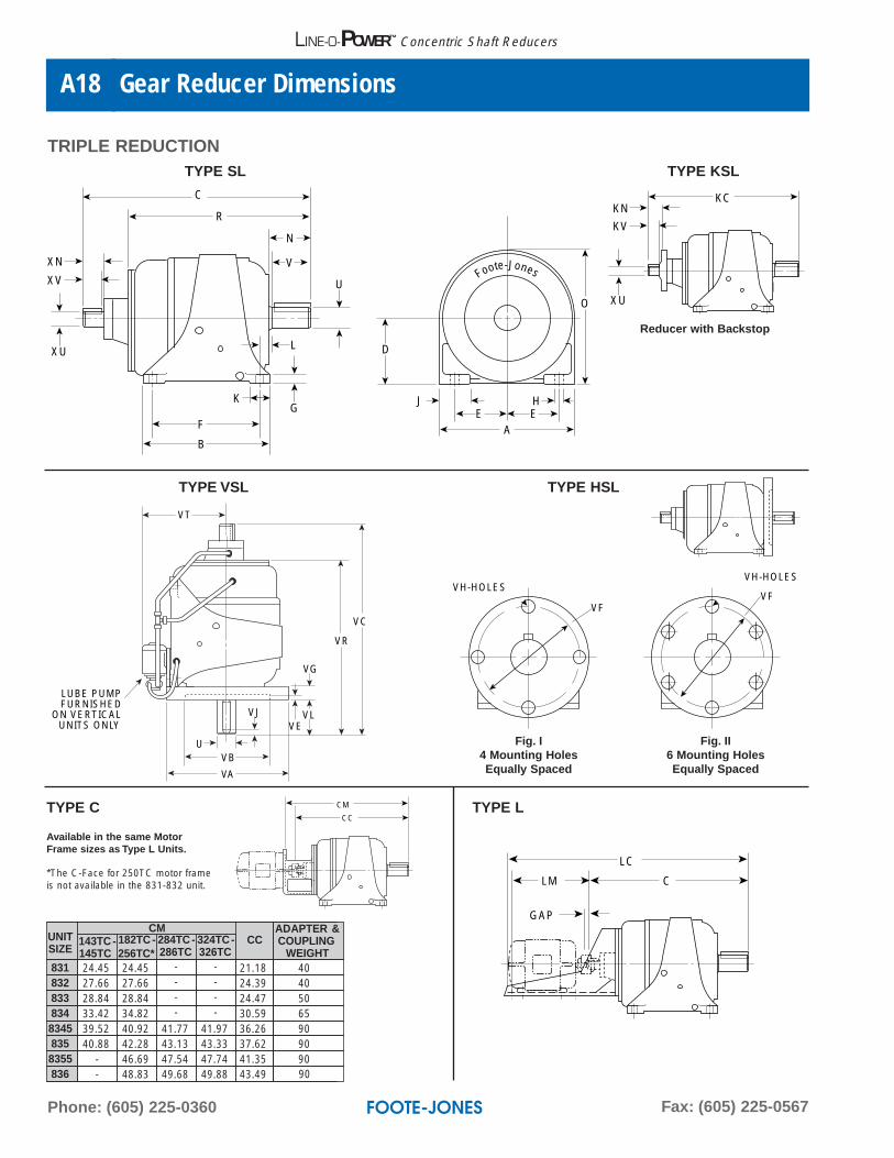
TYPE SL TYPE KSL
TRIPLE REDUCTION
TYPE VSL TYPE HSL
VF
VH-HOLESVF
VH-HOLES
VT
VJ
VB
VR
VG
VEVL
VC
VA
U
LUBE PUMPFURNISHED
ON VERTICALUNITS ONLY
CC
CMTYPE C TYPE L
Available in the same MotorFrame sizes as Type L Units.
*The C-Face for 250TC motor frameis not available in the 831-832 unit. LM C
GAP
LC
Fig. I4 Mounting HolesEqually Spaced
Fig. II6 Mounting HolesEqually Spaced
Reducer with Backstop
UNITSIZE
CMCC
ADAPTER &COUPLING
WEIGHT143TC -145TC
182TC -256TC*
284TC -286TC
324TC -326TC
831 24.45 24.45 - - 21.18 40832 27.66 27.66 - - 24.39 40833 28.84 28.84 - - 24.47 50834 33.42 34.82 - - 30.59 658345 39.52 40.92 41.77 41.97 36.26 90835 40.88 42.28 43.13 43.33 37.62 908355 - 46.69 47.54 47.74 41.35 90836 - 48.83 49.68 49.88 43.49 90
Web: www.footejones.comE-mail: [email protected]
Gear Reducer Dimensions A19
A
LINE-O-POWER™ Concentric Shaft Reducers
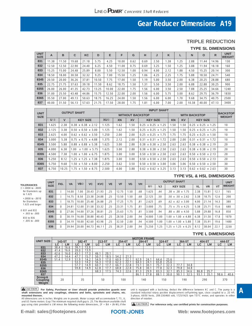
TYPE SL DIMENSIONS
TRIPLE REDUCTION
UNITSIZE
A B C KC D E F G H J K L N O R UNITWEIGHT
831 11.38 11.50 19.68 21.18 5.75 4.25 10.00 0.62 0.69 2.50 1.38 1.25 2.88 11.44 14.96 130
832 12.50 12.50 22.90 24.40 6.25 4.50 11.00 0.75 0.69 3.25 1.50 1.25 3.88 11.94 18.18 160
833 15.25 15.00 24.48 25.89 8.00 5.50 12.50 1.00 0.94 4.00 2.12 1.88 4.50 15.25 20.14 300
834 18.50 18.00 30.58 32.32 9.25 7.00 15.50 1.25 1.06 4.25 2.25 1.75 5.88 18.50 24.71 540
8345 20.50 20.00 36.26 37.81 10.50 7.75 17.00 1.50 1.19 5.00 3.50 2.00 6.38 20.25 28.88 680
835 22.75 21.75 37.63 39.18 11.50 8.62 18.75 1.50 1.31 5.50 3.50 2.00 6.88 22.88 30.25 900
8355 26.00 26.00 41.35 42.73 13.25 10.00 22.00 1.75 1.56 6.00 3.50 2.50 7.88 25.25 34.66 1240
836 31.00 25.50 43.48 44.86 15.75 12.50 22.00 2.00 1.56 6.00 5.75 3.00 8.62 29.75 36.79 1830
8365 35.50 27.00 49.13 50.63 18.75 16.25 24.00 1.50 1.56 6.00 6.00 1.70 9.68 34.75 40.75 2500
837 40.00 31.50 56.13 57.63 21.75 17.50 28.00 1.75 1.81 6.00 7.00 2.00 10.38 40.00 47.13 3400
UNITSIZE
OUTPUT SHAFTINPUT SHAFT
BACKSTOPWEIGHT
WITHOUT BACKSTOP WITH BACKSTOP
U ① V KEY SIZE XU① XN XV KEY SIZE KN KV KEY SIZE
831 1.625 2.38 0.38 x 0.38 x 2.12 1.125 1.62 1.50 0.25 x 0.25 x 1.25 1.50 1.50 0.25 x 0.25 x 1.25 10
832 2.125 3.38 0.50 x 0.50 x 3.00 1.125 1.62 1.50 0.25 x 0.25 x 1.25 1.50 1.50 0.25 x 0.25 x 1.25 10
833 2.625 4.00 0.62 x 0.62 x 3.50 1.250 2.00 2.00 0.25 x 0.25 x 1.75 1.75 1.75 0.25 x 0.25 x 1.50 10
834 3.000 5.38 0.75 x 0.75 x 4.88 1.375 2.12 2.00 0.31 x 0.31 x 1.72 2.00 2.00 0.31 x 0.31 x 1.72 10
8345 3.500 5.88 0.88 x 0.88 x 5.38 1.625 3.00 2.88 0.38 x 0.38 x 2.50 2.63 2.63 0.38 x 0.38 x 2.19 20
835 4.000 6.38 1.00 x 1.00 x 5.75 1.625 3.00 2.88 0.38 x 0.38 x 2.50 2.63 2.63 0.38 x 0.38 x 2.19 20
8355 4.500 7.38 1.00 x 1.00 x 6.75 1.875 3.00 3.00 0.50 x 0.50 x 2.50 2.63 2.63 0.50 x 0.50 x 2.13 20
20836 5.250 8.12 1.25 x 1.25 x 7.38 1.875 3.00 3.00 0.50 x 0.50 x 2.50 2.63 2.63 0.50 x 0.50 x 2.13
8365 5.750 9.68 1.50 x 1.50 x 8.00 2.250 3.62 3.50 0.50 x 0.50 x 3.00 3.06 3.06 0.50 x 0.50 x 2.50 30
30837 6.750 10.25 1.75 x 1.50 x 8.75 2.500 4.00 3.88 0.62 x 0.62 x 3.25 3.13 3.13 0.62 x 0.62 x 2.63
TYPE VSL & HSL DIMENSIONSUNITSIZE
FIG. VA VB➁ VC KVC VE VF VG VHOUTPUT SHAFT UNIT
WEIGHTU① VJ KEY SIZE VL VR VT
831 I 14.00 7.00 20.43 21.93 .25 12.75 1.50 .68 1.625 .44 .38 x .38 x 1.75 2.38 15.81 12.1 165
832 I 14.75 8.50 23.38 24.88 .25 13.50 1.50 .68 2.125 .50 .50 x .50 x 2.62 3.38 18.75 12.6 200
833 I 18.75 10.00 25.48 26.88 .25 17.25 1.75 .81 2.625 .69 .62 x .62 x 3.00 4.00 21.14 14.3 380
834 II 24.81 12.00 31.58 33.32 .25 23.31 1.75 .81 3.000 .75 .75 x .75 x 4.25 5.38 25.71 15.6 680
8345 II 27.06 14.00 37.26 38.81 .25 25.63 1.75 .81 3.500 .94 .88 x .88 x 4.50 5.88 29.88 16.8 850
835 II 30.19 16.00 38.88 40.43 .25 28.50 2.00 .94 4.000 1.00 1.00 x 1.00 x 4.88 6.38 31.50 17.8 1070
8355 II 34.19 18.00 42.60 43.98 .25 32.50 2.00 .94 4.500 1.00 1.00 x 1.00 x 5.88 7.38 35.91 19.6 1480
836 II 39.94 20.00 44.73 46.1 1 .25 38.31 2.00 .94 5.250 1.25 1.25 x 1.25 x 6.25 8.12 38.04 22.1 2230
TYPE L DIMENSIONS
UNIT SIZEMOTOR FRAME
143-5T 182-4T 213-5T 254-6T 284-6T 324-6T 364-5T 404-5T 444-5TLC LM LC LM LC LM LC LM LC LM LC LM LC LM LC LM LC LM
831 38.4 16.6 36.1 13.9832 41.4 16.6 39.0 13.9833 42.6 16.0 43.1 17.3 46.1 20.1834 47.2 14.4 47.7 15.7 50.7 18.5 54.2 21.3
8345 51.4 12.9 51.9 14.2 54.9 17.0 60.9 22.1 62.9 24.1 64.4 25.6835 53.3 14.2 56.3 17.0 62.3 22.1 64.3 24.1 65.8 25.6
8355 57.7 14.9 60.7 17.7 66.7 22.8 73.1 30.1 75.7 32.3 77.7 34.8836 59.8 14.9 62.8 17.7 68.8 22.8 75.8 30.1 77.8 32.3 79.8 34.8
8365 68.3 17.5 74.3 22.6 81.3 29.9 83.3 32.1 85.3 34.6 86.8 35.7
CouplingWeight
20 35 50 100 140 150 190 290 370
837 86.1 27.8 88.1 30.0 90.1 32.5 93.1 35.1 98.6 40.6Scoop &
For Safety, Purchaser or User should provide protective guards overshaft extensions and any couplings, sheaves and belts, sprockets and chains, etc.mounted thereon.All dimensions are in inches. Weights are in pounds. Motor scoops will accommodate T, TS, U,and US frame motors. Gap:The minimum required shaft gap is .25.The Maximum available shaftgap using slots provided is LM minus the following motor dimensions, 2F + BA + (N-W); if the
unit is equipped with a backstop, deduct the difference between KC and C. The pump is a standard industrial rotary positive displacement self-priming type, close coupled to a .33 HP, 3-phase, 60/50 hertz, 208-230/460 volt, 1725/1425 rpm TEFC motor, and operates in eitherdirection of rotation.
For reference only; use certified prints for construction purposes.
CAUTION
CAUTION
TOLERANCES➀ +.0000 to -.0005
for Diameters up to 1.625
+.0000 to -.0010 for Diameters 1.625 and larger
➁ 831 and 832+ .003 to -.000
833 to 836 + .005 to -.000
Phone: (605) 225-0360 Fax: (605) 225-0567
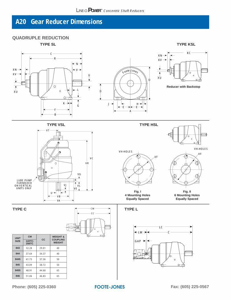
Gear Reducer DimensionsA20
LINE-O-POWER™ Concentric Shaft Reducers
C
R
N
U
GK
L
V
EH
AE
J
O
D
F
B
XU
XN
XV Foote-Jones
XU
KN
KV
KC
TYPE SL TYPE KSL
QUADRUPLE REDUCTION
TYPE VSL TYPE HSLVT
VJ
VB
VR
VG
VEVL
VC
VA
U
LUBE PUMPFURNISHED
ON VERTICALUNITS ONLY
CC
CMTYPE C TYPE L
LM C
GAP
LC
VF
VH-HOLESVF
VH-HOLES
Fig. I4 Mounting HolesEqually Spaced
Fig. II6 Mounting HolesEqually Spaced
UNITSIZE
CMCC
WEIGHT &COUPLING
WEIGHT
843 32.28 29.01 40
844 37.64 34.37 40
8445 41.73 37.36 50
845 43.09 38.72 50
8455 48.91 44.68 65
846 51.06 46.83 65
143TC-256TC
Reducer with Backstop
Web: www.footejones.comE-mail: [email protected]
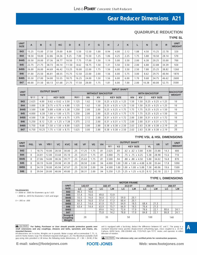
Gear Reducer Dimensions A21
A
LINE-O-POWER™ Concentric Shaft Reducers
TYPE SL
UNITSIZE
A B C KC D E F G H J K L N O RUNIT
WEIGHT
843 15.25 15.00 27.50 29.00 8.00 5.50 12.50 1.00 0.94 4.00 2.12 1.88 4.50 15.25 22.78 320
844 18.50 18.00 32.86 34.36 9.25 7.00 15.50 1.25 1.06 4.25 2.25 1.75 5.88 18.50 28.14 570
8445 20.50 20.00 37.36 38.77 10.50 7.75 17.00 1.50 1.19 5.00 3.50 2.00 6.38 20.25 33.00 700
845 22.75 21.75 38.73 40.14 11.50 8.62 18.75 1.50 1.31 5.50 3.50 2.00 6.88 22.88 34.39 920
8455 26.00 26.00 44.69 46.42 13.25 10.00 22.00 1.75 1.56 6.00 3.50 2.50 7.88 25.25 38.82 1260
846 31.00 25.50 46.81 48.55 15.75 12.50 22.00 2.00 1.56 6.00 5.75 3.00 8.62 29.75 40.94 1870
8465 35.50 27.00 54.00 55.55 18.75 16.25 24.00 1.50 1.56 6.00 6.00 1.70 9.68 34.75 46.62 2600
847 40.00 31.50 60.13 61.68 21.75 17.50 28.00 1.75 1.81 6.00 7.00 2.00 10.38 40.00 52.75 3500
UNITSIZE
OUTPUT SHAFTINPUT SHAFT
BACKSTOPWEIGHT
WITHOUT BACKSTOP WITH BACKSTOP
U ① V KEY SIZE XU① XN XV KEY SIZE KN KV KEY SIZE
843 2.625 4.00 0.62 x 0.62 x 3.50 1.125 1.62 1.50 0.25 x 0.25 x 1.25 1.50 1.50 0.25 x 0.25 x 1.25 10
844 3.000 5.38 0.75 x 0.75 x 4.88 1.125 1.62 1.50 0.25 x 0.25 x 1.25 1.50 1.50 0.25 x 0.25 x 1.25 10
8445 3.500 5.88 0.88 x 0.88 x 5.38 1.250 2.00 2.00 0.25 x 0.25 x 1.75 1.75 1.75 0.25 x 0.25 x 1.50 10
845 4.000 6.38 1.00 x 1.00 x 5.75 1.250 2.00 2.00 0.25 x 0.25 x 1.75 1.75 1.75 0.25 x 0.25 x 1.50 10
8455 4.500 7.38 1.00 x 1.00 x 6.75 1.375 2.12 2.00 0.31 x 0.31 x 1.72 2.00 2.00 0.31 x 0.31 x 1.72 10
846 5.250 8.12 1.25 x 1.25 x 7.38 1.375 2.12 2.00 0.31 x 0.31 x 1.72 2.00 2.00 0.31 x 0.31 x 1.72 10
8465 5.750 9.68 1.50 x 1.50 x 8.00 1.625 3.00 2.88 0.38 x 0.38 x 2.50 2.63 2.63 0.38 x 0.38 x 2.19 20
847 6.750 10.25 1.75 x 1.50 x 8.75 1.625 3.00 2.88 0.38 x 0.38 x 2.50 2.63 2.63 0.38 x 0.38 x 2.19 20
TYPE VSL & HSL DIMENSIONS
UNITSIZE
FIG. VA VB➁ VC KVC VE VF VG VHOUTPUT SHAFT
VR VTUNIT
WEIGHTU① VJ KEY SIZE VL
843 I 18.75 10.00 28.50 30.00 .25 17.25 1.75 .81 2.625 .69 .62 x .62 x 3.00 4.00 23.88 14.3 400
844 II 24.81 12.00 33.60 35.10 .25 23.31 1.75 .81 3.000 .75 .75 x .75 x 4.25 5.38 28.98 15.6 710
8445 II 27.06 14.00 38.36 39.77 .25 25.63 1.75 .81 3.500 .94 .88 x .88 x 4.50 5.88 34.02 16.8 870
845 II 30.19 16.00 39.98 41.39 .25 28.50 2.00 .94 4.000 1.00 1.00 x 1.00 x 4.88 6.38 35.64 17.8 1090
8455 II 34.19 18.00 45.94 47.67 .25 32.50 2.00 .94 4.500 1.00 1.00 x 1.00 x 5.88 7.38 40.06 19.6 1500
846 II 39.94 20.00 48.06 49.80 .25 38.31 2.00 .94 5.250 1.25 1.25 x 1.25 x 6.25 8.12 42.18 22.1 2270
TYPE L DIMENSIONS
UNIT SIZE
MOTOR FRAME143-5T 182-4T 213-5T 254-6T 284-5T
LC LM LC LM LC LM LC LM LC LM843 46.3 16.6844 51.4 16.6 49.0 13.98445 55.5 16.0 56.0 17.3 59.0 20.1845 56.9 16.0 57.4 17.3 60.4 20.18455 61.3 14.4 61.9 15.7 64.9 18.5 68.4 21.3846 63.4 14.4 63.9 15.7 66.9 18.5 70.4 21.38465 69.6 14.2 72.6 17.0 78.6 22.1 80.6 24.1847 75.8 14.2 78.8 17.0 84.8 22.1 86.8 24.1
Scoop &Coupling
Weight20 35 50 100 140
QUADRUPLE REDUCTION
For Safety, Purchaser or User should provide protective guards overshaft extensions and any couplings, sheaves and belts, sprockets and chains, etc.mounted thereon.All dimensions are in inches. Weights are in pounds. Motor scoops will accommodate T, TS, U,and US frame motors. Gap: The minimum required shaft gap is .25. The Maximum available shaftgap using slots provided is LM minus the following motor dimensions, 2F + BA + (N-W); if the
unit is equipped with a backstop, deduct the difference between KC and C. The pump is a standard industrial rotary positive displacement self-priming type, close coupled to a .33 HP, 3-phase, 60/50 hertz, 208-230/460 volt, 1725/1425 rpm TEFC motor, and operates in eitherdirection of rotation.
For reference only; use certified prints for construction purposes.
CAUTION
CAUTION
TOLERANCES➀ +.0000 to -.0005 for Diameters up to 1.625
+.0000 to -.0010 for Diameters 1.625 and larger
➁ + .005 to -.000
Phone: (605) 225-0360 Fax: (605) 225-0567
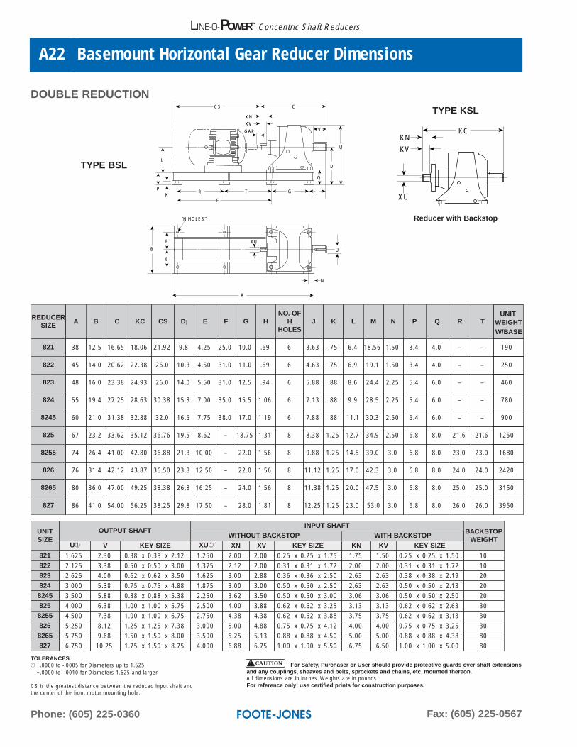
Basemount Horizontal Gear Reducer DimensionsA22
LINE-O-POWER™ Concentric Shaft Reducers
DOUBLE REDUCTION
L
PK
E
U
XU
N
E
B
R
F
T G J
V
C
D
M
Q
CS
XNXV
GAP
A
“H HOLES”
XU
KN
KV
KC
REDUCERSIZE
A B C KC CS D¡ E F G HNO. OF
HHOLES
J K L N P
821 38 12.5 16.65 18.06 21.92 9.8 4.25 25.0 10.0 .69 6 3.63 .75 6.4 1.50 3.4
822 45 14.0 20.62 22.38 26.0 10.3 4.50 31.0 11.0 .69 6 4.63 .75 6.9 1.50 3.4
823 48 16.0 23.38 24.93 26.0 14.0 5.50 31.0 12.5 .94 6 5.88 .88 8.6 2.25 5.4
824 55 19.4 27.25 28.63 30.38 15.3 7.00 35.0 15.5 1.06 6 7.13 .88 9.9 2.25 5.4
8245 60 21.0 31.38 32.88 32.0 16.5 7.75 38.0 17.0 1.19 6 7.88 .88 11.1 2.50 5.4
825 67 23.2 33.62 35.12 36.76 19.5 8.62 – 18.75 1.31 8 8.38 1.25 12.7 2.50 6.8
8255 74 26.4 41.00 42.80 36.88 21.3 10.00 – 22.0 1.56 8 9.88 1.25 14.5 3.0 6.8
826 76 31.4 42.12 43.87 36.50 23.8 12.50 – 22.0 1.56 8 11.12 1.25 17.0 3.0 6.8
8265 80 36.0 47.00 49.25 38.38 26.8 16.25 – 24.0 1.56 8 11.38 1.25 20.0 3.0 6.8
827 86 41.0 54.00 56.25 38.25 29.8 17.50 – 28.0 1.81 8 12.25 1.25 23.0 3.0 6.8 8.0
8.0
8.0
8.0
8.0
6.0
6.0
6.0
4.0
4.0
Q
26.0
25.0
24.0
23.0
21.6
–
–
–
–
–
R
26.0
25.0
24.0
23.0
21.6
–
–
–
–
–
T
3950
3150
2420
1680
1250
900
780
460
250
190
UNITWEIGHTW/BASE
M
18.56
19.1
24.4
28.5
30.3
34.9
39.0
42.3
47.5
53.0
TYPE KSL
UNITSIZE
OUTPUT SHAFT
827 6.750
INPUT SHAFT
10.25 1.75 x 1.50 x 8.75 4.000 6.88 6.75 1.00 x 1.00 x 5.50
BACKSTOPWEIGHT
6.75 6.50 1.00 x 1.00 x 5.00 80
U① V KEY SIZE XU① XN XV KEY SIZE KN KV KEY SIZE821 1.625 2.30 0.38 x 0.38 x 2.12 1.250 2.00 2.00 0.25 x 0.25 x 1.75 1.75 1.50 0.25 x 0.25 x 1.50 10822 2.125 3.38 0.50 x 0.50 x 3.00 1.375 2.12 2.00 0.31 x 0.31 x 1.72 2.00 2.00 0.31 x 0.31 x 1.72 10823 2.625 4.00 0.62 x 0.62 x 3.50 1.625 3.00 2.88 0.36 x 0.36 x 2.50 2.63 2.63 0.38 x 0.38 x 2.19 20824 3.000 5.38 0.75 x 0.75 x 4.88 1.875 3.00 3.00 0.50 x 0.50 x 2.50 2.63 2.63 0.50 x 0.50 x 2.13 208245 3.500 5.88 0.88 x 0.88 x 5.38 2.250 3.62 3.50 0.50 x 0.50 x 3.00 3.06 3.06 0.50 x 0.50 x 2.50 20825 4.000 6.38 1.00 x 1.00 x 5.75 2.500 4.00 3.88 0.62 x 0.62 x 3.25 3.13 3.13 0.62 x 0.62 x 2.63 308255 4.500 7.38 1.00 x 1.00 x 6.75 2.750 4.38 4.38 0.62 x 0.62 x 3.88 3.75 3.75 0.62 x 0.62 x 3.13 30826 5.250 8.12 1.25 x 1.25 x 7.38 3.000 5.00 4.88 0.75 x 0.75 x 4.12 4.00 4.00 0.75 x 0.75 x 3.25 308265 5.750 9.68 1.50 x 1.50 x 8.00 3.500 5.25 5.13 0.88 x 0.88 x 4.50 5.00 5.00 0.88 x 0.88 x 4.38 80
WITH BACKSTOPWITHOUT BACKSTOP
Reducer with Backstop
TYPE BSL
TOLERANCES➀ +.0000 to -.0005 for Diameters up to 1.625
+.0000 to -.0010 for Diameters 1.625 and larger
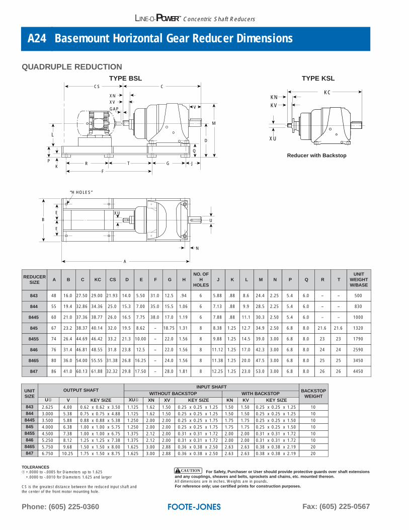
CS is the greatest distance between the reduced input shaft andthe center of the front motor mounting hole.
For Safety, Purchaser or User should provide protective guards over shaft extensionsand any couplings, sheaves and belts, sprockets and chains, etc. mounted thereon.All dimensions are in inches. Weights are in pounds.For reference only; use certified prints for construction purposes.
CAUTION
Web: www.footejones.comE-mail: [email protected]
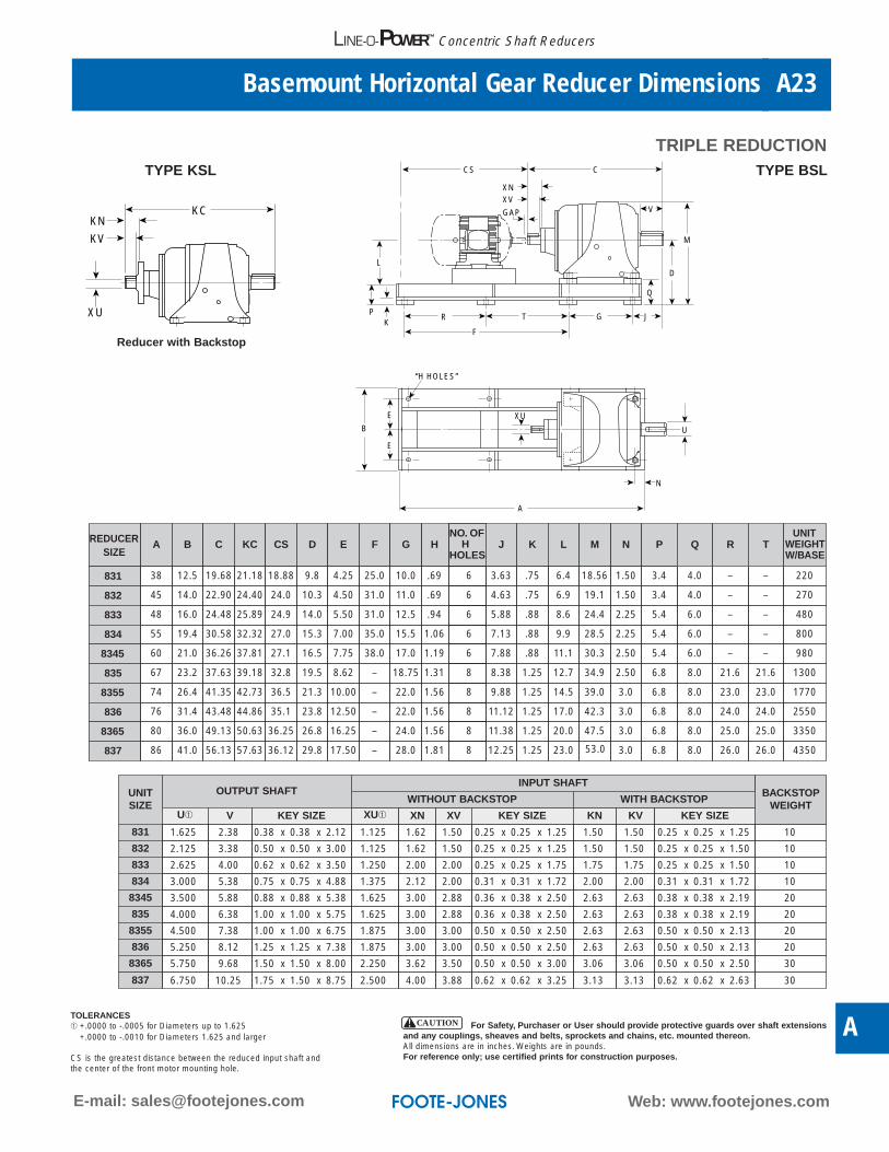
Basemount Horizontal Gear Reducer Dimensions A23
A
LINE-O-POWER™ Concentric Shaft Reducers
TRIPLE REDUCTION
L
PK
E
U
XU
N
E
B
R
F
T G J
V
C
D
M
Q
CS
XNXV
GAP
A
“H HOLES”
XU
KN
KV
KC
TYPE KSL
UNITSIZE
OUTPUT SHAFT
837 6.750
INPUT SHAFT
10.25 1.75 x 1.50 x 8.75 2.500 4.00 3.88 0.62 x 0.62 x 3.25
BACKSTOPWEIGHT
3.13 3.13 0.62 x 0.62 x 2.63 30
U➀ V KEY SIZE XU➀ XN XV KEY SIZE KN KV KEY SIZE
831 1.625 2.38 0.38 x 0.38 x 2.12 1.125 1.62 1.50 0.25 x 0.25 x 1.25 1.50 1.50 0.25 x 0.25 x 1.25 10
832 2.125 3.38 0.50 x 0.50 x 3.00 1.125 1.62 1.50 0.25 x 0.25 x 1.25 1.50 1.50 0.25 x 0.25 x 1.50 10
833 2.625 4.00 0.62 x 0.62 x 3.50 1.250 2.00 2.00 0.25 x 0.25 x 1.75 1.75 1.75 0.25 x 0.25 x 1.50 10
834 3.000 5.38 0.75 x 0.75 x 4.88 1.375 2.12 2.00 0.31 x 0.31 x 1.72 2.00 2.00 0.31 x 0.31 x 1.72 10
8345 3.500 5.88 0.88 x 0.88 x 5.38 1.625 3.00 2.88 0.36 x 0.38 x 2.50 2.63 2.63 0.38 x 0.38 x 2.19 20
835 4.000 6.38 1.00 x 1.00 x 5.75 1.625 3.00 2.88 0.36 x 0.38 x 2.50 2.63 2.63 0.38 x 0.38 x 2.19 20
8355 4.500 7.38 1.00 x 1.00 x 6.75 1.875 3.00 3.00 0.50 x 0.50 x 2.50 2.63 2.63 0.50 x 0.50 x 2.13 20
836 5.250 8.12 1.25 x 1.25 x 7.38 1.875 3.00 3.00 0.50 x 0.50 x 2.50 2.63 2.63 0.50 x 0.50 x 2.13 20
8365 5.750 9.68 1.50 x 1.50 x 8.00 2.250 3.62 3.50 0.50 x 0.50 x 3.00 3.06 3.06 0.50 x 0.50 x 2.50 30
WITHOUT BACKSTOP WITH BACKSTOP
SIZEA B C KC CS D E F G H
NO.H J K L N P
831 38 12.5 19.68 21.18 18.88 9.8 4.25 25.0 10.0 .69 6 3.63 .75 6.4 1.50 3.4
832 45 14.0 22.90 24.40 24.0 10.3 4.50 31.0 11.0 .69 6 4.63 .75 6.9 1.50 3.4
833 48 16.0 24.48 25.89 24.9 14.0 5.50 31.0 12.5 .94 6 5.88 .88 8.6 2.25 5.4
834 55 19.4 30.58 32.32 27.0 15.3 7.00 35.0 15.5 1.06 6 7.13 .88 9.9 2.25 5.4
8345 60 21.0 36.26 37.81 27.1 16.5 7.75 38.0 17.0 1.19 6 7.88 .88 11.1 2.50 5.4
835 67 23.2 37.63 39.18 32.8 19.5 8.62 – 18.75 1.31 8 8.38 1.25 12.7 2.50 6.8
8355 74 26.4 41.35 42.73 36.5 21.3 10.00 – 22.0 1.56 8 9.88 1.25 14.5 3.0 6.8
836 76 31.4 43.48 44.86 35.1 23.8 12.50 – 22.0 1.56 8 11.12 1.25 17.0 3.0 6.8
8365 80 36.0 49.13 50.63 36.25 26.8 16.25 – 24.0 1.56 8 11.38 1.25 20.0 3.0 6.8
837 86 41.0 56.13 57.63 36.12 29.8 17.50 – 28.0 1.81 8 12.25 1.25 23.0 3.0 6.8 8.0
8.0
8.0
8.0
8.0
6.0
6.0
6.0
4.0
4.0
Q
26.0
25.0
24.0
23.0
21.6
–
–
–
–
–
R
26.0
25.0
24.0
23.0
21.6
–
–
–
–
–
T
4350
3350
2550
1770
1300
980
800
480
270
220
UNITWEIGHTW/BASE
M
18.56
19.1
24.4
28.5
30.3
34.9
39.0
42.3
47.5
53.0
HOLES
REDUCER OF
Reducer with Backstop
TYPE BSL
TOLERANCES➀ +.0000 to -.0005 for Diameters up to 1.625
+.0000 to -.0010 for Diameters 1.625 and larger
CS is the greatest distance between the reduced input shaft andthe center of the front motor mounting hole.
For Safety, Purchaser or User should provide protective guards over shaft extensionsand any couplings, sheaves and belts, sprockets and chains, etc. mounted thereon.All dimensions are in inches. Weights are in pounds.For reference only; use certified prints for construction purposes.
CAUTION
Phone: (605) 225-0360 Fax: (605) 225-0567
Basemount Horizontal Gear Reducer DimensionsA24
LINE-O-POWER™ Concentric Shaft Reducers
QUADRUPLE REDUCTION
L
PK
E
U
N
E
B
R
F
T G J
V
C
D
M
Q
CS
XNXV
GAP
A
“H HOLES”
XU
XU
KN
KV
KC
Reducer with Backstop
REDUCERSIZE
A B C KC CS D E F G HNO. OF
HHOLES
J K M N P
843 48 16.0 27.50 29.00 21.93 14.0 5.50 31.0 12.5 .94 6 5.88 .88 24.4 2.25 5.4
844 55 19.4 32.86 34.36 25.0 15.3 7.00 35.0 15.5 1.06 6 7.13 .88 28.5 2.25 5.4
8445 60 21.0 37.36 38.77 26.0 16.5 7.75 38.0 17.0 1.19 6 7.88 .88 30.3 2.50 5.4
845 67 23.2 38.37 40.14 32.0 19.5 8.62 – 18.75 1.31 8 8.38 1.25 34.9 2.50 6.8
8455 74 26.4 44.69 46.42 33.2 21.3 10.00 – 22.0 1.56 8 9.88 1.25 39.0 3.00 6.8
846 76 31.4 46.81 48.55 31.8 23.8 12.5 – 22.0 1.56 8 11.12 1.25 42.3 3.00 6.8
8465 80 36.0 54.00 55.55 31.38 26.8 16.25 – 24.0 1.56 8 11.38 1.25 47.5 3.00 6.8
847 86 41.0 60.13 61.88 32.32 29.8 17.50 – 28.0 1.81 8 12.25 1.25 53.0 3.00 6.8 8.0
8.0
8.0
8.0
8.0
6.0
6.0
6.0
Q
26
25
24
23
21.6
–
–
–
R
26
25
24
23
21.6
–
–
–
T
4450
3450
2590
1790
1320
1000
830
500
UNITWEIGHTW/BASE
L
8.6
9.9
11.1
12.7
14.5
17.0
20.0
23.0
UNITSIZE
OUTPUT SHAFTINPUT SHAFT
BACKSTOPWEIGHT
WITH BACKSTOPU① V KEY SIZE XU① XN XV KEY SIZE KN KV KEY SIZE
843 2.625 4.00 0.62 x 0.62 x 3.50 1.125 1.62 1.50 0.25 x 0.25 x 1.25 1.50 1.50 0.25 x 0.25 x 1.25 10844 3.000 5.38 0.75 x 0.75 x 4.88 1.125 1.62 1.50 0.25 x 0.25 x 1.25 1.50 1.50 0.25 x 0.25 x 1.25 108445 3.500 5.88 0.88 x 0.88 x 5.38 1.250 2.00 2.00 0.25 x 0.25 x 1.75 1.75 1.75 0.25 x 0.25 x 1.50 10845 4.000 6.38 1.00 x 1.00 x 5.75 1.250 2.00 2.00 0.25 x 0.25 x 1.75 1.75 1.75 0.25 x 0.25 x 1.50 108455 4.500 7.38 1.00 x 1.00 x 6.75 1.375 2.12 2.00 0.31 x 0.31 x 1.72 2.00 2.00 0.31 x 0.31 x 1.72 10846 5.250 8.12 1.25 x 1.25 x 7.38 1.375 2.12 2.00 0.31 x 0.31 x 1.72 2.00 2.00 0.31 x 0.31 x 1.72 108465 5.750 9.68 1.50 x 1.50 x 8.00 1.625 3.00 2.88 0.36 x 0.38 x 2.50 2.63 2.63 0.38 x 0.38 x 2.19 20847 6.750 10.25 1.75 x 1.50 x 8.75 1.625 3.00 2.88 0.36 x 0.38 x 2.50 2.63 2.63 0.38 x 0.38 x 2.19 20
WITHOUT BACKSTOP
TYPE BSL TYPE KSL
TOLERANCES➀ +.0000 to -.0005 for Diameters up to 1.625
+.0000 to -.0010 for Diameters 1.625 and larger
CS is the greatest distance between the reduced input shaft andthe center of the front motor mounting hole.
For Safety, Purchaser or User should provide protective guards over shaft extensionsand any couplings, sheaves and belts, sprockets and chains, etc. mounted thereon.All dimensions are in inches. Weights are in pounds.For reference only; use certified prints for construction purposes.
CAUTION
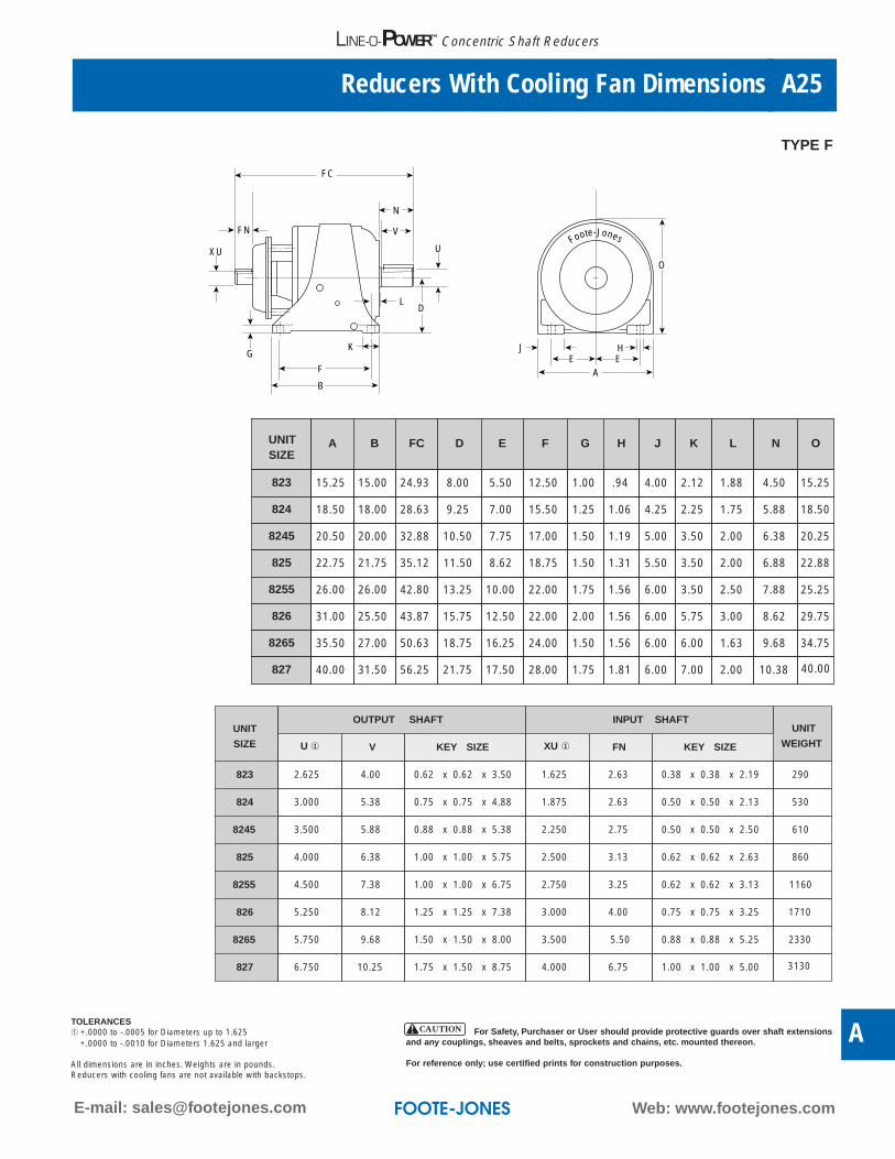
Web: www.footejones.comE-mail: [email protected]
Reducers With Cooling Fan Dimensions A25
A
LINE-O-POWER™ Concentric Shaft Reducers
EH
AE
J
O
FC
N
U
GK
V
F
B
XU
FNFoote-Jones
LD
UNIT SIZE
A B FC D E F G H J K L N O
823 15.25 15.00 24.93 8.00 5.50 12.50 1.00 .94 4.00 2.12 1.88 4.50 15.25
824 18.50 18.00 28.63 9.25 7.00 15.50 1.25 1.06 4.25 2.25 1.75 5.88 18.50
8245 20.50 20.00 32.88 10.50 7.75 17.00 1.50 1.19 5.00 3.50 2.00 6.38 20.25
825 22.75 21.75 35.12 11.50 8.62 18.75 1.50 1.31 5.50 3.50 2.00 6.88 22.88
8255 26.00 26.00 42.80 13.25 10.00 22.00 1.75 1.56 6.00 3.50 2.50 7.88 25.25
826 31.00 25.50 43.87 15.75 12.50 22.00 2.00 1.56 6.00 5.75 3.00 8.62 29.75
8265 35.50 27.00 50.63 18.75 16.25 24.00 1.50 1.56 6.00 6.00 1.63 9.68 34.75
827 40.00 31.50 56.25 21.75 17.50 28.00 1.75 1.81 6.00 7.00 2.00 10.38 40.00
UNIT
SIZE
OUTPUT SHAFT INPUT SHAFTUNIT
WEIGHTU ① V KEY SIZE XU ① FN KEY SIZE
823 2.625 4.00 0.62 x 0.62 x 3.50 1.625 2.63 0.38 x 0.38 x 2.19 290
824 3.000 5.38 0.75 x 0.75 x 4.88 1.875 2.63 0.50 x 0.50 x 2.13 530
8245 3.500 5.88 0.88 x 0.88 x 5.38 2.250 2.75 0.50 x 0.50 x 2.50 610
825 4.000 6.38 1.00 x 1.00 x 5.75 2.500 3.13 0.62 x 0.62 x 2.63 860
8255 4.500 7.38 1.00 x 1.00 x 6.75 2.750 3.25 0.62 x 0.62 x 3.13 1160
826 5.250 8.12 1.25 x 1.25 x 7.38 3.000 4.00 0.75 x 0.75 x 3.25 1710
8265 5.750 9.68 1.50 x 1.50 x 8.00 3.500 5.50 0.88 x 0.88 x 5.25 2330
827 6.750 10.25 1.75 x 1.50 x 8.75 4.000 6.75 1.00 x 1.00 x 5.00 3130
TYPE F
TOLERANCES➀ +.0000 to -.0005 for Diameters up to 1.625
+.0000 to -.0010 for Diameters 1.625 and larger
All dimensions are in inches. Weights are in pounds.Reducers with cooling fans are not available with backstops.
For Safety, Purchaser or User should provide protective guards over shaft extensionsand any couplings, sheaves and belts, sprockets and chains, etc. mounted thereon.
For reference only; use certified prints for construction purposes.
CAUTION

Phone: (605) 225-0360 Fax: (605) 225-0567
LINE-O- Mount Horizontal Gear Reducer DimensionsA26
LINE-O-POWER™ Concentric Shaft Reducers
DOUBLE REDUCTION
C
MCME
G
U
XU
K
LV
N
H
F
B
MD
O
XD
DXN
XV
MF
E E
A
J
MA
MB
XU
KN
KV
KC
POSITION NO. 3
POSITION NO. 2
OPTIONAL MOUNTING POSITIONS
TYPE KSL
REDUCER WITH BACKSTOP
Where shown, riser blocks producing XD dimensionwill be furnished to provide floor line clearance ofmotor bracket when side mounted.
UNIT SIZE A B C KC D E F G H J K L N OUNIT
WEIGHT
821 11.38 11.50 16.65 18.06 5.75 4.25 10.00 0.62 0.69 2.50 1.38 1.25 2.25 11.44 140
822 12.50 12.50 20.62 22.38 6.25 4.50 11.00 0.75 0.69 3.25 1.50 1.25 3.25 11.94 180
823 15.25 15.00 23.38 24.93 8.00 5.50 12.50 1.00 0.94 4.00 2.12 1.88 3.50 15.25 385
824 18.50 18.00 27.25 28.63 9.25 7.00 15.50 1.25 1.06 4.25 2.25 1.75 4.63 18.50 710
8245 20.50 20.00 31.38 32.88 10.50 7.75 17.00 1.50 1.19 5.00 3.50 2.00 5.13 20.25 800
825 22.75 21.75 33.62 35.12 11.50 8.62 18.75 1.50 1.31 5.50 3.50 2.00 5.63 22.88 1055
8255 26.00 26.00 41.00 42.80 13.25 10.00 22.00 1.75 1.56 6.00 3.50 2.50 6.63 25.25 1365
826 31.00 25.50 42.12 43.87 15.75 12.50 22.00 2.00 1.56 6.00 5.75 3.00 8.25 29.75 1930
8265 35.50 27.00 47.00 49.25 18.75 16.25 24.00 1.50 1.56 6.00 6.00 1.63 10.00 34.75 2600
TYPE PSL
TOLERANCES➀ +.0000 to -.0005 for Diameters up to 1.625
+.0000 to -.0010 for Diameters 1.625 and larger
All dimensions are in inches. Weights are in pounds.Unit weight includes reducer and motor mounts.
For Safety, Purchaser or User should provide protective guards over shaft extensionsand any couplings, sheaves and belts, sprockets and chains, etc. mounted thereon.
For reference only; use certified prints for construction purposes.
CAUTION
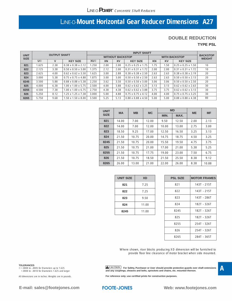
Web: www.footejones.comE-mail: [email protected]
LINE-O-Mount Horizontal Gear Reducer Dimensions A27
A
LINE-O-POWER™ Concentric Shaft Reducers
UNITSIZE
OUTPUT SHAFTINPUT SHAFT
BACKSTOPWEIGHT
WITHOUT BACKSTOP WITH BACKSTOPU① V KEY SIZE XU① XN XV KEY SIZE KN KV KEY SIZE
821 1.625 2.38 0.38 x 0.38 x 2.12 1.250 2.00 2.00 0.25 x 0.25 x 1.75 1.75 1.50 0.25 x 0.25 x 1.50 10
822 2.125 3.38 0.50 x 0.50 x 3.00 1.375 2.12 2.00 0.31 x 0.31 x 1.72 2.00 2.00 0.31 x 0.31 x 1.72 10
823 2.625 4.00 0.62 x 0.62 x 3.50 1.625 3.00 2.88 0.38 x 0.38 x 2.50 2.63 2.63 0.38 x 0.38 x 2.19 20
824 3.000 5.38 0.75 x 0.75 x 4.88 1.875 3.00 3.00 0.50 x 0.50 x 2.50 2.63 2.63 0.50 x 0.50 x 2.13 20
8245 3.500 5.88 0.88 x 0.88 x 5.38 2.250 3.62 3.50 0.50 x 0.50 x 3.00 3.06 3.06 0.50 x 0.50 x 2.50 20
825 4.000 6.38 1.00 x 1.00 x 5.75 2.500 4.00 3.88 0.62 x 0.62 x 3.25 3.13 3.13 0.62 x 0.62 x 2.63 30
8255 4.500 7.38 1.00 x 1.00 x 6.75 2.750 4.38 4.38 0.62 x 0.62 x 3.88 3.75 3.75 0.62 x 0.62 x 3.13 30
826 5.250 8.12 1.25 x 1.25 x 7.38 3.000 5.00 4.88 0.75 x 0.75 x 4.12 4.00 4.00 0.75 x 0.75 x 3.25 30
8265 5.750 9.68 1.50 x 1.50 x 8.00 3.500 5.25 5.13 0.88 x 0.88 x 4.50 5.00 5.00 0.88 x 0.88 x 4.38 80
DOUBLE REDUCTION
UNITSIZE
MA MB MCMD
ME MFMIN. MAX.
821 14.00 7.00 12.00 9.50 12.50 2.00 2.13
822 14.00 7.00 12.00 10.00 13.00 2.75 3.00
823 18.50 9.25 17.00 12.50 16.50 3.25 3.13
824 21.50 10.75 20.00 14.75 18.75 4.50 3.25
8245 21.50 10.75 20.00 15.50 19.50 4.75 3.75
825 21.50 10.75 21.00 17.00 21.00 5.38 5.25
8255 21.50 10.75 17.75 19.00 23.00 7.50 6.75
826 21.50 10.75 18.50 21.50 25.50 8.38 9.12
8265 26.00 13.00 21.00 22.00 26.00 8.38 10.88
Where shown, riser blocks producing XD dimension will be furnished toprovide floor line clearance of motor bracket when side mounted.
UNIT SIZE XD
821 7.25
822 7.25
823 9.50
11.00
8245 11.00
PSL SIZE MOTOR FRAMES
821 143T - 215T
822 143T - 215T
823 143T - 286T
824 182T - 326T
8245 182T - 326T
825 182T - 326T
8255 254T - 326T
826 254T - 326T
8265 284T - 365T
TYPE PSL
TOLERANCES➀ +.0000 to -.0005 for Diameters up to 1.625
+.0000 to -.0010 for Diameters 1.625 and larger
All dimensions are in inches. Weights are in pounds.
For Safety, Purchaser or User should provide protective guards over shaft extensionsand any couplings, sheaves and belts, sprockets and chains, etc. mounted thereon.
For reference only; use certified prints for construction purposes.
CAUTION
824

Phone: (605) 225-0360 Fax: (605) 225-0567
LINE-O-Mount Horizontal Gear Reducer DimensionsA28
LINE-O-POWER™ Concentric Shaft Reducers
TRIPLE REDUCTION
C
MCME
G
U
XU
K
LV
N
H
F
B
MD
O
DXN
XV
MF
E E
A
J
MA
MB
XU
KN
KV
KC
TYPE KSL
REDUCER WITH BACKSTOP
POSITION NO. 3
POSITION NO. 2
OPTIONAL MOUNTING POSITIONS
UNIT SIZE A B C KC D E F G H J K L N OUNIT
WEIGHT
831 11.38 11.50 19.68 21.18 5.75 4.25 10.00 0.62 0.69 2.50 1.38 1.25 2.88 11.44 154
832 12.50 12.50 22.90 24.40 6.25 4.50 11.00 0.75 0.69 3.25 1.50 1.25 3.88 11.94 185
833 15.25 15.00 24.48 25.89 8.00 5.50 12.50 1.00 0.94 4.00 2.12 1.88 4.50 15.25 371
834 18.50 18.00 30.58 32.32 9.25 7.00 15.50 1.25 1.06 4.25 2.25 1.75 5.88 18.50 617
8345 20.50 20.00 36.26 37.81 10.50 7.75 17.00 1.50 1.19 5.00 3.50 2.00 6.38 20.25 845
835 22.75 21.75 37.63 39.18 11.50 8.62 18.75 1.50 1.31 5.50 3.50 2.00 6.88 22.88 1081
8355 26.00 26.00 41.35 42.73 13.25 10.00 20.00 1.75 1.56 6.00 3.50 2.50 7.88 25.25 1426
836 31.00 25.50 43.48 44.86 15.75 12.50 22.00 2.00 1.56 6.00 5.75 3.00 8.62 29.75 2077
8365 35.50 27.00 49.13 50.63 18.75 16.25 24.00 1.50 1.56 6.00 6.00 1.63 9.87 34.75 2863
TYPE PSL
TOLERANCES➀ +.0000 to -.0005 for Diameters up to 1.625
+.0000 to -.0010 for Diameters 1.625 and larger
All dimensions are in inches. Weights are in pounds.Unit weight includes reducer and motor mounts.
For Safety, Purchaser or User should provide protective guards over shaft extensionsand any couplings, sheaves and belts, sprockets and chains, etc. mounted thereon.
For reference only; use certified prints for construction purposes.
CAUTION
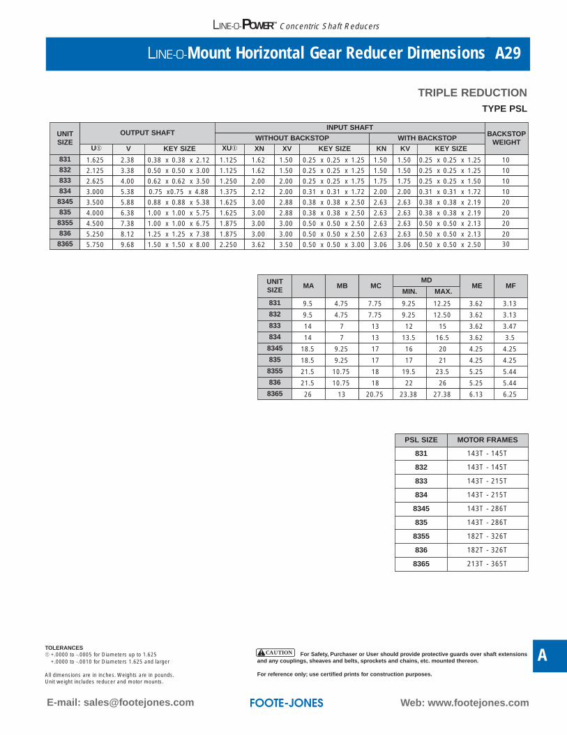
Web: www.footejones.comE-mail: [email protected]
LINE-O-Mount Horizontal Gear Reducer Dimensions A29
A
LINE-O-POWER™ Concentric Shaft Reducers
TRIPLE REDUCTION
UNITSIZE
OUTPUT SHAFTINPUT SHAFT
BACKSTOPWEIGHT
WITHOUT BACKSTOP WITH BACKSTOPU① V KEY SIZE XU① XN XV KEY SIZE KN KV KEY SIZE
831 1.625 2.38 0.38 x 0.38 x 2.12 1.125 1.62 1.50 0.25 x 0.25 x 1.25 1.50 1.50 0.25 x 0.25 x 1.25 10832 2.125 3.38 0.50 x 0.50 x 3.00 1.125 1.62 1.50 0.25 x 0.25 x 1.25 1.50 1.50 0.25 x 0.25 x 1.25 10833 2.625 4.00 0.62 x 0.62 x 3.50 1.250 2.00 2.00 0.25 x 0.25 x 1.75 1.75 1.75 0.25 x 0.25 x 1.50 10834 3.000 5.38 0.75 x0.75 x 4.88 1.375 2.12 2.00 0.31 x 0.31 x 1.72 2.00 2.00 0.31 x 0.31 x 1.72 108345 3.500 5.88 0.88 x 0.88 x 5.38 1.625 3.00 2.88 0.38 x 0.38 x 2.50 2.63 2.63 0.38 x 0.38 x 2.19 20835 4.000 6.38 1.00 x 1.00 x 5.75 1.625 3.00 2.88 0.38 x 0.38 x 2.50 2.63 2.63 0.38 x 0.38 x 2.19 208355 4.500 7.38 1.00 x 1.00 x 6.75 1.875 3.00 3.00 0.50 x 0.50 x 2.50 2.63 2.63 0.50 x 0.50 x 2.13 20836 5.250 8.12 1.25 x 1.25 x 7.38 1.875 3.00 3.00 0.50 x 0.50 x 2.50 2.63 2.63 0.50 x 0.50 x 2.13 208365 5.750 9.68 1.50 x 1.50 x 8.00 2.250 3.62 3.50 0.50 x 0.50 x 3.00 3.06 3.06 0.50 x 0.50 x 2.50 30
UNITSIZE
MA MB MCMD
ME MFMIN. MAX.
831 9.5 4.75 7.75 9.25 12.25 3.62 3.13
832 9.5 4.75 7.75 9.25 12.50 3.62 3.13
833 14 7 13 12 15 3.62 3.47
834 14 7 13 13.5 16.5 3.62 3.5
8345 18.5 9.25 17 16 20 4.25 4.25
835 18.5 9.25 17 17 21 4.25 4.25
8355 21.5 10.75 18 19.5 23.5 5.25 5.44
836 21.5 10.75 18 22 26 5.25 5.44
8365 26 13 20.75 23.38 27.38 6.13 6.25
PSL SIZE MOTOR FRAMES
831 143T - 145T
832 143T - 145T
833 143T - 215T
834 143T - 215T
8345 143T - 286T
835 143T - 286T
8355 182T - 326T
836 182T - 326T
8365 213T - 365T
TYPE PSL
TOLERANCES➀ +.0000 to -.0005 for Diameters up to 1.625
+.0000 to -.0010 for Diameters 1.625 and larger
All dimensions are in inches. Weights are in pounds.Unit weight includes reducer and motor mounts.
For Safety, Purchaser or User should provide protective guards over shaft extensionsand any couplings, sheaves and belts, sprockets and chains, etc. mounted thereon.
For reference only; use certified prints for construction purposes.
CAUTION
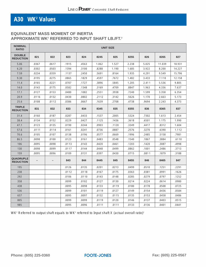
Phone: (605) 225-0360 Fax: (605) 225-0567
WK2 ValuesA30
LINE-O-POWER™ Concentric Shaft Reducers
EQUIVALENT MASS MOMENT OF INERTIAAPPROXIMATE WK2 REFERRED TO INPUT SHAFT LB./FT.2
NOMINALRATIO
UNIT SIZE
DOUBLEREDUCTION 821 822 823 824 8245 825 8255 826 8265 827
5.06 .0367 .0617 .1915 .4563 1.062 1.527 2.238 5.025 11.039 18.931
6.20 .0302 .0503 .1394 .3100 .8288 1.190 1.685 3.922 8.200 14.227
7.59 .0234 .0359 .1137 .2450 .5691 .8164 1.935 4.291 9.549 15.796
9.30 .0195 .0275 .0865 .1829 .4597 .7672 1.482 3.433 7.110 12.158
11.4 .0165 .0221 .0707 .1727 .3896 .5845 1.205 2.41 1 5.536 9.805
14.0 .0143 .0175 .0582 .1348 .3169 .4709 .8847 1.963 4.336 7.637
17.1 .0127 .0153 .0480 .1082 .2551 .3938 .7240 1.599 3.358 6.354
20.9 .0116 .0132 .0430 .0802 .2112 .3142 .5626 1.170 2.663 5.173
25.6 .0108 .0112 .0386 .0667 .1639 .2708 .4738 .9694 2.243 4.373
TRIPLEREDUCTION 831 832 833 834 8345 835 8355 836 8365 837
31.4 .0160 .0187 .0287 .0433 .1537 .2005 .5324 .7302 1.613 2.454
38.4 .0134 .0152 .0229 .0427 .1125 .1436 .3618 .6501 1.175 1.990
47.1 .0123 .0135 .0190 .0244 .0903 .1120 .3349 .4417 .8312 1.604
57.6 .0111 .0114 .0161 .0241 .0736 .0887 .2576 .3270 .6390 1.112
70.6 .0105 .0107 .0138 .0196 .0577 .0669 .1996 .2485 .5158 .7981
86.5 .0098 .0100 .0123 .0161 .0483 .0548 .1540 .1867 .3884 .6110
106 .0095 .0098 .0113 .0143 .0420 .0461 .1203 .1420 .3087 .4998
130 .0098 .0099 .0117 .0144 .0448 .0499 .0862 .1001 .2486 .3713
159 .0095 .0096 .0109 .0131 .0397 .0430 .0715 .081 1 .1879 .3188
QUADRUPLEREDUCTION – – 843 844 8445 845 8455 846 8465 847
195 .0126 .0135 .0201 .0213 .0499 .0510 .1251 .2291
238 .0112 .0118 .0167 .0175 .0363 .0381 .0991 .1626
292 .0106 .0110 .0143 .0148 .0285 .0279 .0797 .1252
358 .0099 .0102 .0127 .0130 .0214 .0224 .0614 .0980
438 .0095 .0098 .0133 .0119 .0180 .0178 .0508 .0725
536 .0099 .0101 .0119 .0127 .0149 .0154 .0436 .0584
657 .0095 .0097 .0132 .0115 .0135 .0153 .0458 .0486
805 .0099 .0099 .0119 .0120 .0146 .0137 .0403 .0515
985 .0095 .0096 .0111 .0111 .0133 .0136 .0401 .0441
WK2 Referred to output shaft equals to WK2 referred to Input shaft X (actual overall ratio)2
Related Documents