System 1 System Manual version 0.2 Manual version 0.2 February 2007 PO Box 87 19 Demott St. Lacona, New York 13083 PHONE 315-387-3414 FAX 315-387-3415 TOLL FREE US/CAN 800-441-3414 www.biospherix.com 1. First, adapt the generic chamber. In the “ Adapting a Generic Chamber” manual, refer to the: “ Inst allation Overview” section, for an overview of how to install the generic chamber. Also use the “ Adapting a Chamber for a ProCO2” section for information and directions on how to adapt the chamber for a ProCO2. 2. Now, installing the ProCO2. In the “ ProCO2 Model 120” manual refer to the: “ BioS pherix Supplied Part s” and “ User Supplied Part s” sections for a parts list. Also refer to the: “ Setup of Gas Supply”, “ ProCO2 Front Panel Inst allation” and “ ProCO2 Back Panel Inst al- lation” for how to make all the connections. 3. Next, familiarize yourself with the push button interface. In the “ ProCO2 Model 120” manual refer to the: “ Operation”, “ Program Functions Menu” and “ Configuration” sections for information regarding the push button interface. 4. Now, calibration. In the “ ProCO2 Model 120” manual refer to the: “ Calibration” section for information on how to calibrate the sensor. 5. Next, tuning. In the “ ProCO2 Model 120” manual refer to the: “ T uning” section for spe- cific information on fine tuning. You shouldn’t have to use this section much, because most tuning is done at the factory. 6. Now, operating. In the “ ProCO2 Model 120” manual refer to the: “ Single Setpoint Con- trol” section for information on how to operate with the ProCO2. Also refer to the: “ Setting the Alarm Setpoint” section for directions for how to set a specific alarm setpoint. 7. Finally, maintenance issues. In all of the manuals refer to; “ Maintenance” sections on how to maintain the respective equipment. “ ProCO2” Manual v1.0 d0207 “Adapting a Generic Chamber” Manual v0.2 d0506 This section will provide you with a list of the order in which the equip- ment should be: installed, setup, calibrated etc. After you have com- pleted a step refer back to this page to see what the next step is. There will be times when the manuals with need to be used in con- junction with one another. This list is here to help you use the equip- ment more efficiently, you should still read all of the manuals thor- oughly before using this list. By reading all of the manuals and then referring to this list you will have a better understanding of how the equipment works. This system consists of many parts. Each part has it’s own manual. The name of the each individual manual and it’s version number are as follows:

Welcome message from author
This document is posted to help you gain knowledge. Please leave a comment to let me know what you think about it! Share it to your friends and learn new things together.
Transcript

System 1System Manual
version 0.2Manualversion 0.2 February 2007
PO Box 8719 Demott St.
Lacona, New York 13083PHONE 315-387-3414
FAX 315-387-3415TOLL FREE US/CAN 800-441-3414
www.biospherix.com
1. First, adapt the generic chamber. In the “Adapting a Generic Chamber” manual, refer to the:“Installation Overview” section, for an overview of how to install the generic chamber. Also usethe “Adapting a Chamber for a ProCO2” section for information and directions on how toadapt the chamber for a ProCO2.
2. Now, installing the ProCO2. In the “ProCO2 Model 120” manual refer to the: “BioSpherixSupplied Parts” and “User Supplied Parts” sections for a parts list. Also refer to the:“Setup of Gas Supply”, “ProCO2 Front Panel Installation” and “ProCO2 Back Panel Instal-lation” for how to make all the connections.
3. Next, familiarize yourself with the push button interface. In the “ProCO2 Model 120”manual refer to the: “Operation”, “Program Functions Menu” and “Configuration” sectionsfor information regarding the push button interface.
4. Now, calibration. In the “ProCO2 Model 120” manual refer to the: “Calibration” sectionfor information on how to calibrate the sensor.
5. Next, tuning. In the “ProCO2 Model 120” manual refer to the: “Tuning” section for spe-cific information on fine tuning. You shouldn’t have to use this section much, because mosttuning is done at the factory.
6. Now, operating. In the “ProCO2 Model 120” manual refer to the: “Single Setpoint Con-trol” section for information on how to operate with the ProCO2. Also refer to the: “Settingthe Alarm Setpoint” section for directions for how to set a specific alarm setpoint.
7. Finally, maintenance issues. In all of the manuals refer to; “Maintenance” sections onhow to maintain the respective equipment.
“ProCO2” Manual v1.0 d0207“Adapting a Generic Chamber” Manualv0.2 d0506
This section will provide you with a list of the order in which the equip-ment should be: installed, setup, calibrated etc. After you have com-
pleted a step refer back to this page to see what the next step is.There will be times when the manuals with need to be used in con-
junction with one another. This list is here to help you use the equip-ment more efficiently, you should still read all of the manuals thor-
oughly before using this list. By reading all of the manuals and thenreferring to this list you will have a better understanding of how the
equipment works.
This system consists of many parts. Eachpart has it’s own manual. The name of theeach individual manual and it’s version
number are as follows:

ProCO2 Model 120
Manualversion 1.0 Feb 2007
This manual is intended to help our customers efficientlysetup and operate the equipment. We encourage not only allinstallers, but also all users, to read this manual thoroughly.
Keep it handy and refer to it often. Save it for futurereference. If you have any problems or questions, please do
not hesitate to call. We are here to help.
IntroductionThe ProCO2 is a versatile and compact gas carbon dioxide controller for people who docarbon dioxide sensitive work. Though designed to work with BioSpherix chambers the
ProCO2 works in incubators, gloveboxes, animal cages, refrigerators,plant growth chambers, and many othersemi-sealable chambers. Practicallyany small-medium enclosure can befitted. Even cardboard boxes andplastic bags. The unit works fromoutside of the host chamber by re-
motely sensing and displacing the air inside the chamber with CO2.
The nominal range of carbon dioxide concetration is 0.1-20.0%. Advanced feedback algo-rithms handle practically any carbon dioxide gas dynamic.Infusion rates are adjustable up to 35 SCFH, sufficient formost lab chambers. Installation is easy. Operation is simple.The unit moves easily from one host chamber to another.Please read and follow the safety and operations instructionson the following pages. Be careful. Any pressurized gas canbe dangerous. Know what you are doing and do it safely.
1ProCO2 model 120
version 1.0
! !Anyone who has not thoroughly read and under-stood this manual, must never attempt to operate
the equipment.
PO Box 8719 Demott St.
Lacona, New York 13083PHONE 315-387-3414
FAX 315-387-3415TOLL FREE US/CAN 800-441-3414
www.biospherix.com

Table of Contents
Safety Instructions........................................................................3
BioSpherix Supplied Parts............................................................4
User Supplied Parts.......................................................................5
Setup of Gas Supply......................................................................6
ProCO2Front Panel Installation.....................................................7
ProCO2 Back Panel Installation....................................................8
Operation........................................................................................9
Program Functions Menu............................................................10
Configuration...............................................................................11
Calibration...............................................................................12-13
Tuning......................................................................................14-17
Single Setpoint Control...............................................................18
Setting the Alarm Setpoint..........................................................19
Maintenance.................................................................................20
Warranty........................................................................................21
2ProCO2 model 120
version 1.0

SAFETY INSTRUCTIONS
ELECTRICAL POWER SOURCE unit should be connected to a power supply only of the type described in the operating instructions or as marked on unit.
POWER CORD PROTECTION power supply cords should be routed so that they are notlikely to be walked on or pinched by items placed upon or against them.
ELECTRIC SHOCK do not remove cover of ProCO2 due to presence of uninsulated "dan-gerous voltage" within product's enclosure.
ELECTRIC SHOCK unit should never be used where it can fall or be pushed into water.
ELECTRIC SHOCK if modifying host chamber, be careful not to drill or cut into electricalwires hidden behind chamber wall. Never drill or cut blindly.
NONUSE PERIODS power cord of unit should be unplugged from electrical outlet when leftunused for long period of time.
FALLING OBJECTS AND LIQUID SPLASH care should be taken so that objects do not fallon equipment and liquids do not spill, splash, or drip onto or into unit enclosure orpower cord.
PRESSURIZED GAS secure all connections with hose clamps. Never exceed pressurelimits. Bleed all lines before disconnecting. Wear safety glasses at all times.
LOW OXYGEN ATMOSPHERES never enter a chamber which has a low oxygen atmo-sphere because of severe danger of suffocation. Host chamber should be in well venti-lated room. Control gas (nitrogen or other low oxygen gas) continuously leaks out ofchamber and should never be allowed to build up in room outside of chamber.
HIGH OXYGEN ATMOSPHERES never enter a chamber which has a high oxygen atmo-sphere due to danger of oxygen toxicity. Never smoke or allow any source of fire orspark in or around a chamber with high oxygen atmosphere. Oxygen radically promotescombustion and can be explosive. Host chamber should always be in well ventilatedroom. Oxygen continuously leaks out of chamber and should never be allowed to buildup in room outside chamber.
VENTILATION unit should be situated so that its' location or position does not interferewith proper ventilation. Neither ProCO2 nor host chamber should be in poorly ventilatedareas.
HEAT unit should be situated away from heat sources such as radiators, heat registers,stoves, or other appliances or processes that produce heat.
CLEANING do not immerse unit in water. Do not wipe unit with wet cloth or sponge orpaper. Clean only with a dry cloth.
3ProCO2 model 120
version 1.0

BioSpherix Supplied Parts
This section will familiarize you with the components that come withthe ProCO2.
12VDC power supply
Gas FittingsInfusion tubing
Calibration chamberwith tubing
Carbon dioxide gas sensor and sensor cable
ProCO2 unit
4ProCO2 model 120
version 1.0
Short piece of 1/8 in. IDtubing

User Supplied Parts 5ProCO2 model 120
version 1.0
1. Qty. 2 regulators, either a one stage regulator or a two staged regulator. Either way youwill need two gauges, one for the amount of gas in the tank and one for the gas coming outof the tank. (2500 PSIG input 0-60 PSIG output, recommended). PSIG stands for Poundsper Square Inch Gauge as opposed to PSIA which stands for Pounds per Square InchAbsolute.
2. Qty. 1 compressed gas source (tank) of carbon dioxide.
3. Qty. 1 compressed gas source (tank) of carbon dioxide/oxygen mix (ratio should be 10-90).
4. Qty. 1 compressed gas source (tank) of nitrogen (optional, see “Calibration” section forinformation).
This section will list the parts that the user will need to supply in order tooperate the equipment.

Control gas must be supplied through a 1/8 in. ID tube to the back panel of theProCO2. If the tubing coming from the compressed gas source (tank) isn’t 1/8 in. then useone of the provided gas fittings to adapt the tubing to 1/8 in. The pressure must be regu-lated to 0-25 PSIG. For best results use approximately 2 PSIG in aCulture Chamber anduse 15 PSIG in an Animal Chamber. (refer to “Tuning” section under the “Power” headingfor further information). Do not connect any tubing yet, wait until told to do so in the “Cali-bration” section and “Single Setpoint Control” section.
The amount of gas used is determined by how the chamber is used, not the ProCO2.The ProCO2 uses the least amount of gas possible, which is only what the chamber needs.The amount of gas used is dependent on: (1) The size and leakiness of the chamber, (2)The amount of times and how long the chamber door(s) are opened, (3) The carbon diox-ide level being controlled.
Use a one or a two stage, 2500 PSIG input, 0-60 PSIG output regulator at the sourceof the compressed gas. It is best to have two gauges so that you can monitor the amountof gas in the compressed source and also monitor the amount passing through the output.Never allow the pressure coming out of the compressed source to exceed 25 PSIG ordamage will occur to the ProCO2. If the regulator is not near the ProCO2 then thereshould be a shutoff valve placed upstream of the unit. When taking off gas supply tubealways make sure to shut off compressed gas at the source first, then bleed the pressureout of the line and then take off the tube from back of ProCO2.
Step-by-Step Procedure for Connecting Gas to Machine
1. Before connecting the regulator to the tank, close the regulator and make sure the tankis also closed off.
2. Connect the regulator to the compressed nitrogen (if applicable), compressed carbondioxide and to the compressed carbon dioxide/oxygen mix gas sources.
3. Connect the tubing from each compressed gas source to the ProCO2 when told to do soin the calibration procedures and the operation procedures.
4. At this point you don’t have to open the regulator or turn on the gas. You will be turningthe gas on at the beginning of the calibration/single setpoint control procedures, for nowjust connect the regulator.
Setup of Gas Supply
This section will describe how to setup the gas supply, for informationon how to connect the gas supply to the machine, see the calibration
sections and the “Single Setpoint Control” section.
6ProCO2 model 120
version 1.0

ProCO2 Front Panel Installation
The following steps will explain how to set up the ProCO2 front paneland prepare it for installation to a chamber.
1. Placing the UnitPlace the unit on a level secure surface either on the
chamber or within seven feet of the chamber. Make sureyou can easily access the front panel.
2. Gas Connected ProperlyEach time you connect a gas supply, make sure that
the gas is connected properly open the bleed valve byturning the knob on the front of the ProCO2 counterclock-wise. If gas is heard expelling out the “BLEED” barb onthe front panel then the gas is connected properly. Onceyou have confirmed then close the valve. Do this afteryou have followed the procedure in the “Setup of GasSupply” section and are beginning either operation orcalibration.
3. Connecting Calibration ChamberAttach the calibration chamber by connecting the
1/16 in. ID tubing to the barb labeled “BLEED” on thefront of the ProCO2, when calibrating.
4. Gas and Alarm SwitchesFlip the “GAS” switch up to allow the gas to flow to
the chamber. Flip the “ALARM” switch down to enablethe alarm to sound.
2
3
4
7ProCO2 model 120
version 1.0

ProCO2 Back Panel Installation 8ProCO2 model 120
version 1.0
3. Connecting SensorPlug the sensor cable into the port labeled
“SENSOR” on back of ProCO2 by twisting the sensorcable into the port until it pushes in, then push in until“click is heard. When removing pull the ring back andpull cable off. Plug the other end of the sensor cable intothe sensor itself by lining up the key on the terminal withthe key on the connector of the sensor cable. Push inand twist the ring on. The display on the front of theProCO2 should respond.
2. Connecting GasAttach 1/8 in. ID tubing to hose barb labeled “IN” on
the back of the ProCO2. Making sure that the gas com-ing in Never exceeds 25 PSIG or damage will occur tothe ProCO2. Depending on if you are calibrating oroperating will determine what type of gas you will beusing. (see “Calibration” and “Single Setpoint Control”sections).
1. Power Supply Plug the jack end into the port labeled “12VDC” onback of ProCO2. Plug the 12VDC power supply into awall outlet. The display on the front of ProCO2 shouldturn on.
4. Connecting Infusion TubeAttach 1/8 in. infusion tube to “OUT” barb on back of
ProCO2.
1
4
2
3
This section will describe how to setup the back panel of the ProCO2.

This section will give an overview of some of the different modes andfunctions within the ProCO2
RESET ALARM/ERRORMESSAGESWhen the alarm orerror condition hasbeen cleared,momentarily pressboth upkey anddownkey at the
same time.
CHANGE SETPOINTPress and hold starkey. Press up key toincrease setpoint.Press downkey todecrease setpoint. Ifchange requirescontrol output, SP1indicator will flash.
VIEW SETPOINTIn work mode,press and holdstar key. Setpointis shown inalternating display.
CHANGE OPTIONIndex to required function. Press andhold star key (current optiondisplayed). Press up and/or down keys
to display new setting.Release star key.IMPORTANT: Checknew selection(alternating withfunction) beforemoving to anotherfunction or exiting
program mode.
VIEW FUNCTION/OPTIONOn release of up ordown key atfunction, displayalternates with theoption selected.
ENTER/EXIT PROGRAM MODESimultaneously hold both up and downkeys for 3 seconds. You enter
program mode fromnormal operatingmode at the tunefunction on level 1 inthe menu. You exitprogram mode atany point in the
menu, returning to normal operatingmode. With exit, any new instructionsget entered into memory.
ENTRY TO HIDDEN LEVEL 4At "VEr" function onlevel 3, press and holdboth upkey anddownkeysimultaneously for 10seconds. To enter level4
PROGRAM MODEAll configuration, calibration,
and tuning operations take place inprogram mode. You access theprogram menu, navigate through it,select appropriate options, and exitback to work mode.
Entry into menu is always atsame point, the "tunE" function onlevel 1.
During programming, controlwith existing settings is maintained.New settings are written to memoryonly upon exiting program mode.Settings are retained in non-volatilememory for years even if unit isunpowered.
Security locks can configurecertain options unadjustable. How-ever, all functions and locked op-tions may be viewed even whenlocked.
Exit program mode from anyplace in menu. Exiting programmode returns to work mode with newsettings.
WORK MODEWork mode is the normal day-
to-day operating mode. Whethercontrolling or not (parked), carbondioxide concentration at the sensoris continuously displayed, unlesspre-empted by other operations.
Operations in work mode arelimited to: (1) view setpoint, (2)change setpoint, (3) reset alarm/error message, (4) enter programmode.
CHANGE LEVELSMulti-level menu of functions requiresnavigating from level to level.
Index down key tolevel function.
Release down keyto display currentlevel.
Press and hold starkey while usingdown key or up keyto select new level.
Release star key todisplay new level.
SINGLE LEVEL NAVIGATIONPress upor downkey onceto move tothe nextfunction.
Hold up or down keys to automaticallyindex through the functions. Alwaysindex down to get to level function.
OPERATION 9ProCO2 model 120
version 1.0
Sele
ct A
utot
une o
r Par
k
Prop
ortio
nal B
and /
Gai
nor
Dea
d ba
nd w
idth
Inte
gral
time /
Res
et(A
utom
atic
offs
et)
Der
ivat
ive t
ime /
Rat
e
Der
ivativ
e app
roac
hco
ntro
l
Prop
ortio
nal c
ycle
-tim
eor
ON
/OFF
Offs
et / M
anua
l rese
t
Lock
mai
n set
poin
t SP1
Adju
st al
arm
SP2
setp
oint
Sel
ect S
P2
dead
band
wid
th o
rP
ropo
rtion
al b
and
Sele
ct S
P2 O
N/O
FFor
Cyc
le-ti
me
Rea
d con
trol S
P1ou
tput
pow
er %
SP1 m
anua
l pow
erco
ntro
l %
Set S
P1 po
wer
limit %
Set S
P2 po
wer
limit %
Subs
idia
ry al
arm
SP2
mod
e: la
tch/
sequ
ence
Mai
n ala
rm S
P2m
ode:
stra
tegy
.
Sele
ct di
spla
y res
olut
ion
(dec
imal
poin
t)
Set s
cale
max
imum
Set s
cale
min
imum
Sele
ct se
nsor
inpu
t
Rea
d SP1
cont
rol
outp
ut de
vice
Rea
d SP2
alar
mou
tput
devi
ce
Burn
-out
prot
ectio
n
Sele
ct ou
tput
mod
es:
Dire
ct/R
ever
se
Selec
t SP1
/SP2
L.E.
D. m
odes
Sens
or sp
an ad
just
Sens
or ze
ro ad
just
Sele
ct co
ntro
lac
cura
cy m
onito
r
Rea
d mon
itor r
esul
ts
Rea
d Aut
otun
etu
ning
data
Func
tions
rese
t
Der
ivat
ive s
ensi
tivity
Dis
play
sens
itivi
ty
Disa
ble a
larm
annu
ncia
tor
Disa
ble p
rogr
amau
to-e
xit
Secu
rity l
ock
Softw
are v
ersio
n
2
1
4
3
PROGRAM ENTRY POINT
PROGRAM FUNCTIONS MENU
Sele
ct un
its of
mea
sure
men
t
PROGRAM MODE FUNCTIONS MENU is arranged on 4 levels. Entry into menu isbottom of level 1. Exit menu from any point. Level 4 is hidden for security;there's one way in. Menu items are loosely grouped together according tosimilar functions. Some functions are defaults(hard or soft). Some are read only. Some are onlyactive depending on other function settings. Someare used only in rare instances. Chances are99.99% you'll have to become intimately familiarwith only a few of the important ones.
10ProCO2 model 120
version 1.0

11ProCO2 model 120
version 1.0
CONFIGURATION
Extensive configuration options in alarming, security, and displayfunctions all can be set later, if necessary. Only one main
configuration setting is required to start carbon dioxide level
SECONDARYCONFIGURATIONS
Alarm configuration options in-clude deviation, band, and fullscale.Output can be reverse or direct act-ing. Alarm intensity is configurableby timed pulse proportioning.
Security options against peopleerrors include set point lock, setpoint range limits, and limited menuaccess to prevent unauthorizedchanges. Burnout contingencies andoutput overload limits protect againstmachine malfunctions.
Display resolution and sensi-tivity, alarm annunciator priority, andflashing indicator lights are adjust-able too.
All these settings are second-ary to the main job of carbon dioxidecontrol. They are explained else-where.
HIGH/LOW CARBON DIOX-IDE
Enter program mode. Navigateto "rEV.d" function on level 3.
Control output is either director reverse. Direct means carbondioxide decreases as output de-creases on approach to set point.Reverse means carbon dioxide in-creases as output decreases on ap-proach to set point.
To control high carbon dioxidelevels, set SP1 (setpoint 1) outputmode to reverse. To control lowcarbon dioxide, set SP1 output modeto direct. Mnemonic: "1r" or "1d".
Alarm SP2 output also sets butis not active until alarm is configured.Set "2r" or"2d" later ifnecessary.

SENSORSThe sensor drives the controller.
If the sensor is not calibrated, it won'tbe accurate. If the sensor is notaccurate, control won't be either.
Every sensor must be calibratedboth (1) initially when installed, newor used, and (2) periodically over thelife of the sensor to compensate forfilm blocking infrared part of sensor.
Sensors generate an electricalsignal (output) which is linear anddirectly proportional with gas carbondioxide concentration:
Although always linear and di-rectly proportional, raw output can bequite different for each sensor:
Sensor output also changes overtime (drift), generally in a slow down-ward direction. Sensors remain linearbut gradually lose power:
CALIBRATION
Calibration is the key to control accuracy. Check calibration onceevery two weeks to have as much confidence as necessary in
accuracy.CALIBRATION
Calibration electronically cor-rects for the difference among sen-sors. Makes raw output line super-impose on calibrated line. Then allsensors read accurately:
Calibration also compensatesfor drift. Monitor drift with periodiccalibration checks. Recalibratewhen necessary:
12ProCO2 model 120
version 1.0
CALIBRATIONSTANDARDS
Sensors are calibrated to stan-dard gas mixtures with known car-bon dioxide concentrations. Sincesensor output is linear, calibrating attwo known points makes all otherpoints accurate as well.
One standard for calibration isa compressed gas source of 10%carbon dioxide and 90% oxygen.Immerse the sensor in gas by usinga calibration chamber. Set the"SPAn" to read "10" in work mode.
Compressed nitrogen can beused as a standard. Immerse sen-sor in control gas by using calibra-tion chamber and bleed valve. Or,you could use room air as the sec-ond standard. In both instances youwould set the "ZEro" to read "0.0".
Of course, other standards canbe used as well. Or calibrate to thirdparty carbon dioxide analyzers. Justbe confident in your standard.
CALIBRATION MENUFUNCTIONS
"SPAn" and "ZEro" functionson level 3 of the menu calibrate thesensor. Both adjust sensor outputline without disrupting linearity, buteach works differently.
The "ZEro" function affects onlythe Y-intercept of the line, not theslope. It moves the line up and downwithout changing the slope. Alwaysdo the "ZEro" function first:
Increasing makes the y-intercept morepositive (moves the line up) -
Decreasing makes the y-interceptmore negative (moves the line down)
The "SPAn" function adjuststhe slope of the line, but does notaffect the Y-intercept (set by "ZEro"function). Always do "SPAn" after"ZEro":
Raising increases slope:
Lowering decreases slope:
REMEMBER: never adjust"ZEro" function without adjusting"SPAn" function afterwards. "ZEro"affects "SPAn" setting, but "SPAn"does not affect "ZEro" setting.

HOW TO USECALIBRATION CHAMBER
The calibration chamber is atool for immersing the sensor in cali-bration gases. It connects to the gassource via 1/16 in. ID tubing. It holdsthe tip of the sensor in the gasstream.
First, connect the calibrationchamber tubing to the "BLEED"hose barb on the front panel of theProCO2.Then insert the sensor tip intothe calibration chamber. The sensorhole is sized for a snug fit and allowsthe sensor to be in the gas streamwithin the chamber:
Finally, open the bleed valveknob on the front panel of the ProCO2until you hear gas expelling slightlythrough the calibration chamber:
CALIBRATIONPROCEDURE FORCARBON DIOXIDECONTROL
There are two ways to cali-brate the "ZEro" setting. The firstway is to use room air as a stan-dard and set the controller toread "0.0", the second way is touse compressed nitrogen as astandard (BioSpherix recom-mends to use nitrogen, as shownin the following instructions).
1. Connect the 1/8 in. ID tubingcoming from the compressed nitro-gen gas source to the "IN" barb onthe back of the ProCO2. Make surethe gas is regulated 0-25 PSIG.Never exceed 25 PSIG. Use ap-proximately 2 PSIG for Culture Cham-ber and use 15 PSIG for an AnimalChamber.
2. Hook up calibration cham-ber to "BLEED" hose barb on frontpanel of ProCO2. Slightly open bleedvalve knob on front panel until youcan hear gas expelling slightlythrough calibration chamber this willestablish a 0% carbon dioxide levelwithin the calibration chamber.
3. Insert sensor tip into calibra-tion chamber and let sensor stabilizein 0% carbon dioxide (minute or two).Watch sensor response to immer-sion in nitrogen in work mode to tellwhen it stabilizes. Note whethercarbon dioxide reading is above orbelow "0.0" and by how much.
4. Enter program mode by hold-ing down the up and down buttons forthree seconds, navigate to"LEVL"function and while holding down the" * " button push the up button untilyou reach "3". Then navigate to the"ZEro" function and raise the settingif reading was low, or decrease thesetting if reading was high.The num-ber in the "ZEro" function stands forthe same amount in work mode. Forexample: if you change the numberin "ZEro" function by ".2" the num-ber in work mode will change by ".2".Exit program mode to see new read-ing by holding the up and down but-tons for three seconds. Repeat untilreading is what it should be "0.0".
5. Close the bleed valve knobthen remove the calibration chambertubing from the "BLEED" barb. Turnoff the nitrogen at the compressedgas source, open the bleed valveknob again and allow the gas toescape out the "BLEED" barb. Whenthe gas has all escaped close thebleed valve knob. Then disconnectthe 1/8 tubing from the "IN" barb onthe back of the ProCO2.
13ProCO2 model 120
version 1.0
6. Connect the carbon dioxide/oxygen mix compressed gas with a1/8 in. ID tubing to the "IN" barb onthe back of the ProCO2. The mixshould be a ratio of 10% (carbondioxide) - 90% (oxygen), check thelabel on the compressed source forexact percentage. Making sure thegas is regulated to 0-25 PSIG. Neverexceed 25 PSIG. Connect the cali-bration chamber tubing to the"BLEED" barb on the front of theProCO2. Slightly open bleed valveknob on the front panel until you canhear gas expelling slightly from cali-bration chamber this will establish a10%-90% ratio of carbon dioxide-oxygen mix within the calibrationchamber.
7. Insert the sensor tip into thecalibration chamber and let the sen-sor stabilize in 10% carbon dioxide(minute or two). Watch sensor re-sponse in work mode to tell when ithas stabilized. Note whether carbondioxide reading is above or below"10.0" and by how much.
8. Enter program mode,change the "LEVL" to "3", navigateto "SPAn" function, and raise thesetting if reading in work mode waslow, or decrease the setting if read-ing in work mode was high. Exitprogram mode to see new reading.Repeat until reading is what it shouldbe "10.0". The number in "SPAn"function isn't an exact corresponsewith the number in work mode, it is acoarse adjustment.
Sensor is calibrated when itreads 0% carbon dioxide after stabi-lization in nitrogen and 10% carbondioxide after stabilization in carbondioxide/oxygen mixture.
When calibration is completeclose the bleed valve knob and dis-connect the calibration chamber tub-ing. Then turn off the compressedgas supply and open the bleed valveknob to expell the remaining gas.Once the gas has all escaped, closethe bleed valve knob, and disconnectthe 1/8 in. tubing from the "IN" barbon the back of the ProCO2. Nowconnect the 100% carbon dioxidegas to the "IN" barb, making sure theregulator is set to 0-25 PSIG. Neverexceed 25 PSIG.
TUNING
Tuning matches control parameters of ProCO2 to gas dynamics ofhost chamber to achieve effective control.
TUNINGDifferent carbon dioxide control
jobs in different chambers requirespecific control parameters. Tuningmeans setting those control param-eters that result in acceptable con-trol.
Which parameters to set, andhow to set them, depends on the job.Is oscillation acceptable? If so howmuch? Is overshoot permissable?Undershoot? How much? For howlong? Is the load fixed or variable?Does setpoint change? Must recov-ery be fast?
Capability exists to handle prac-tically any carbon dioxide control job.However, the more complex and de-manding the job, the more involvedtuning becomes.
Tune only what's necessary toaccomplish the job. Any additionalcontrol parameters probably won'thelp, and might hurt. Excessive tun-ing can reduce control stability.
Most carbon dioxide control jobsare simple. Thus tuning is easy. Onlya few parameters need to be set.Advanced control capabilities are avail-able, but use them only if you need to.
Just watch the control processand see how each control parameteraffects it. This is the only definitiveway. Usually it's the easiest too.
Tuning takes time. It takes gas.It means sitting and watching thecontrol process, sometimes over andover. There is no shortcut. Trial anderror is the only way to tell if a tune setworks. Along with the ProCO2 you areprovided with a "Control ParametersChart", this chart has all the pretuninginformation that was done at the fac-tory. Don't lose this chart, but if youdo then call the number at the front ofthis manual to receive a new copy.
Always change only one controlparameter at a time. See how thatsetting works first, before changinganother. Record each tune set. Whensatisfied with control, copy and setaside for safekeeping.
A tune doesn't have to be per-fect to work. But don't stop shorteither. Once tuning is done and done
right, it may never need further at-tention.
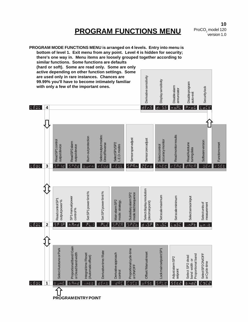
POWERFirst adjust power. Power is
the only control parameter not set inprogram mode. Once power is set,other control parameters may betuned.
Power is a function of infusionrate. The more gas infused per unittime, the higher the power. Infusionrate is adjustable up to 35 SCFH(Standard Cubic Feet an Hour).
Infusion rate is a function ofgas supply delivery pressure. Thehigher the pressure, the faster theinfusion rate. Gas supply deliverypressure is set at the pressure regu-lator on gas source. Infusion rate isdependent on the pressure of thegas coming from the compressedgas source. Never exceed 25PSIG.
ProCO2 power must roughlymatch dynamic gas load of cham-ber. Too little power and it takesforever to reach set point. Too muchpower and control is unstable.
The bigger the chamber, themore power (gas) it takes. Forexample, a small baby incubatormight take 2-5 SCFH , but a tissueculture incubator might take 10-30SCFH.
The leakier the chamber, themore power (gas) it takes. Forexample, an incubator with a tightseal might take 10 SCFH, but onewith a loose seal might take 20SCFH.
There are methods to calcu-late power, but it's faster and easierto adjust power empirically. Watchthe control process and adjust infu-sion rate so ProCO2 is able to delib-erately push carbon dioxide fromambient to past set point undernormal load conditions.
Most jobs can be tuned over arelatively wide power range. Oncethe other control parameters aretuned, however, any change in thepower/load balance may require re-tuning those parameters.
STEPS:1. Set gas supply delivery pressure.
Range 0-25 PSIG.2. Watch the number in work mode
approach the set point. If too fastand unstable, turn down pres-sure to lower infusion rate. If tooslow, turn up pressure toincrease infusion rate. Neverexceed 25 PSIG.
ON/OFF CONTROLCrude basic control. Suitable
when precise carbon dioxide levelsare not necessary.
Infusion stops when carbon di-oxide reaches setpoint and resumesonly when carbon dioxide drifts backpast setpoint. Output is either 100%or 0%. Oscillations are natural.
The only tune adjustment isthe dead band width. Dead bandwidth is distance between on-to-offpoint and off-to-on point above andbelow setpoint. Defines where noswitching occurs, but oscillation doesoccur.
The larger the dead band width,the larger the oscillation, but the lessswitching on and off. Maximize thedead band width to minimize wearand tear on equipment. Set for larg-est acceptable oscillation.
The smaller the dead bandwidth, the less oscillation, but themore wear and tear.
On/off tuning has no provisionfor fluctuating loads. Blindly respondsonly to on-to-off point and off-to-onpoint. Change in load may changeoscillation amplitude and/or period.
14ProCO2 model 120
version 1.0

STEPS:1. For on/off control, enter program
mode, navigate to "CYC.t"function on level 1. Set "on.of".Have to go down to "0" byholding "*" button and pressingdown to get to "on.oF".
2. Then set dead band width. Indexdown to "bAnd" function and setdistance between on-to-off pointand off-to-on point.
PROPORTIONAL CON-TROL
Proportional control eliminatesoscillation. It controls steady-stateby weakening power as carbon diox-ide level approaches setpoint. Whenpower (gas infused per unit time)exactly matches load (gas leakingout per unit time), carbon dioxidestabilizes.
Unlike ON/OFF control wherepower is either 100% or 0%, propor-tional control can adjust power any-where between 100% and 0%. Poweris adjusted by timing gas pulses."Proportional" means gas pulses getproportionately smaller as the dis-tance between carbon dioxide leveland setpoint (SP1) gets smaller.
Pulses are timed by setting acycle time and varied by percentageof the cycle time. Maximum pulsesare 100% of cycle time. Minimumpulses are 0% of cycle time. Propor-tioned pulses are in between.
Timed pulse proportioning oc-curs only over a narrow band of car-bon dioxide levels centered aroundset point. Control gas is infused fullblast (100% output) with no timinguntil it reaches this band. Then itcycles. The deeper it goes into theproportional band, the shorter thepulses. Band size determines howquick pulses shorten and power thusweakens.
Somewhere between 100%and 0% of the cycle time there's apulse time that holds steady state.However, if proportional band is toosmall, it may not be easy to find.Small changes in carbon dioxide willcause huge changes in output, simi-lar to ON/OFF control. Carbon diox-ide will oscillate and never reachsteady state.
On the other hand, if propor-tional band is too wide, proportioninginhibits approach to setpoint. Powerstarts decreasing way to soon.
Proportional band should bebig enough so there's no gross over-shoot everytime proportioning kicksin, but not so big that there's need-less pulsing long before carbon diox-ide level gets even close to setpoint.
Cycle time should be as longas possible to minimize wear andtear on equipment, but not so longthat it becomes unresponsive.
If no other control parametersare set, proportional band centersaround setpoint SP1. All additionalparameters accentuate proportionalcontrol. Without proportional control( prop. band and cycle time), no otherparameters are active. Some affectthe position of the band, but not thesize. Some affect the size, but notthe position. None affect the cycletime.
STEPS:1. To tune proportional control, enter
program mode, navigate to"CYC.t" function on level 1. Setcycle time, anywhere from 0.1 -81 seconds.
2. Then index down to "bAnd"function and set proportionalband. Gas power is reduced, bytime proportioning action, acrossthis band centered around SP1.
3. Exit program mode to work modeand watch control process. Notewhether process overshoots andoscillates, or undershoots fromcycling long before reachingsetpoint.
4. Enter program mode, andnavigate to "bAnd" functionagain. If process overshot andoscillated, increase band size. Ifprocess undershot and took longto reach setpoint, decrease bandsize.
5. Repeat steps 3-4 till steady stateis achieved, whether steady stateis at setpoint or not.
MANUAL OFFSETProportional band is basically
a "blind" control parameter. Whenset alone, it positions itself arbitrarilly,centered around the setpoint.Chances are steady-state will not beat setpoint.
If proportional control steady-state is not at setpoint, the offsetmust be eliminated to move steady-state to setpoint.
Manual Offset moves propor-
tional band by a fixed distance sothat steady-state is at setpoint. Ifsteady-state is +0.3% carbon diox-ide above setpoint, then an offset of-0.3 will move proportional band downso pulse is perfectly proportioned tomatch load at setpoint.
Manual offset works good whencontrolling against a fixed load. Onceset, it makes proportional controlnearly perfect. No overshoot either.
STEPS:1. Watch control process in work
mode till steady state is reached.Note the variance from setpoint.
2. Enter program mode, navigate to"oFSt" function on level 1, andset number that offsets variance.
NOTE: "int.t" function on level 1must be set to "oFF" to manuallyadjust offset, otherwise "oFSt"function is not active but read-only.
INTEGRAL CONTROLAUTOMATIC OFFSETRESET
Proportional control jobs, withfluctuating loads require automaticoffset to keep steady state atsetpoint.
Integral control parameter au-tomatically and continuously moni-tors divergences between setpointand steady state, and acts to correctoffset by repositioning proportionalband. Changes the area between setpoint line and carbon dioxide levelline, and shifts proportional band inproper direction to minimize area.As load changes, steady state fol-lows setpoint if integral is tuned prop-erly.
Integral control overshoots oninitial start up and after significantinterruptions. Far away from setpointit senses big offset, so it shootsproportional band as far as possiblein corrective direction. Only afterpassing setpoint does integral pickup the need to bring proportionalband back to near setpoint.
Integral control parameter istime. Resets offset as frequently asyou specify. If integral time is tooshort, it recalculates too many timesbefore carbon dioxide moves muchand moves proportional band too fartoo fast. Result is oscillation. Even-tually oscillation will dampen to steadystate, if load hasn't changed yet.
If integral time is too long, it'sslow to respond. Steady state andsetpoint take a long time to merge.
15ProCO2 model 120
version 1.0

STEPS:1. Watch carbon dioxide control
process in work mode undernormal load change. Note offsetat one load. While loadchanges, note time till new offsetstabilizes at steady state. Tochange load open the chamberdoor and ventilate.
2. Enter program mode, navigate to"int.t" function on level 1, andset integral time to 30-70% ofnoted time. Range is 0.1 - 60minutes.
3. Exit program mode to work mode.Watch as normal load changesoccur, and note time till offsetsdisappear.
4. Repeat steps 2 and 3 until controlis acceptable.
DERIVATIVE CONTROLThe most demanding control
job is the one that has to be fast andtight under fluctuating loads. Withpower and proportional band tunedaggressively (high power, narrowband), conditions are ripe for over-shoot. Add integral action and over-shoot is virtually guaranteed, atstartup and after large disturbances.
Derivative control suppressesovershoot. It also speeds responseto disturbances, large or small.
Derivative algorithms measurerate and direction of change of car-bon dioxide in relation to setpoint.Then temporarily but quickly shiftsproportional band in opposite direc-tion, by a distance proportional tothe rate of change. The faster thechange, the further it shifts. Shift isjust long enough to "extract" an out-put determination.
The effect is to quickly weakenpower on approach to setpoint, andquickly boost power if carbon dioxidesuddenly pulls away from setpoint.Properly tuned, derivative should notdisturb proportional or integral actionat steady state.
On fast approach to setpointwithout derivative, when carbon diox-ide first hits proportional band the
initial pulse might be 97% of cycletime. That's not very weak. The nextpulse might be significantly less, butby that time it's too late. Carbondioxide changed too fast. Overshootalready occurred. When integralaction finally kicks in, it's way toolate.
With derivative, fast carbon di-oxide change immediately pulls upproportional band. Then first pulsemight be 1% of cycle time. Thisquickly slows approach to setpoint.Slower rate of change calculationmight only "extract" a pulse of 12%of cycle time. Slower still, maybe19%.
As rate of change of carbondioxide decreases, derivative actiondecreases. At steady state there'sno derivative action. Ideally at thatpoint carbon dioxide is near setpointand integral action takes over.
Derivative also speeds re-sponse to disturbances. Without it,as carbon dioxide quickly divergesaway from setpoint, the first pulsefrom proportional control band mightbe only 22% of cycle time, the sec-ond pulse 53%, the third 87%, andby the time output goes to 100%,carbon dioxide is far away.
With derivative, the fast changein carbon dioxide away from setpointwould immediately pull proportionalband back toward setpoint and resultin 100% output before carbon diox-ide gets too far.
Derivative control is hardest totune. Proper setting is very sensitiveto gas dynamics and other controlparameters. If it is not required, keepit off as it will tend to reduce controlstability.
Derivative parameter is time.Sets rate of corrective action. Rule-of-thumb: set 3-8 times faster thanintegral. If too short it inhibits reach-ing setpoint and slows response toupsets. If too long, it oscillates andovercorrects. Is only active in pro-portional band.
STEPS:1. With power, proportional, and
integral parameters set, watchcontrol process in work mode.Note overshoot. Next openchamber briefly to induce largeupset in control. Note speed ofresponse.
2. Enter program mode, navigate to"dEr.t" function on level 1,andset derivative time. Range 0.1 -0.4 of integral time.
3. Exit program mode, air outchamber, watch control processand note overshoot on approachand response to disturbance.
4. Re-enter program mode, andnavigate to "dEr.t" functionagain. If too much overshoot onapproach and too slow responseto upset, decrease derivativetime. If approach to setpoint isinhibited and response undercorrects, increase derivativetime.
5. Repeat steps 3-4 until overshooton approach and response toupset is acceptable.
16ProCO2 model 120
version 1.0

DERIVATIVE APPROACHCONTROL
Derivative action (1) sup-presses overshoot and (2) speedsresponse to upsets. However, it maynot always be possible to do bothwith one setting. Depending on thepower/load balance, sometimes de-rivative tuned for quick response willnot suppress overshoot enough.
Derivative approach controlparameter "dAC" solves this prob-lem. It tunes overshoot independentof normal operating parameters bycontrolling when derivative actionstarts on approach to setpoint. Nor-mally derivative action is only in pro-portional band. "dAC" is a multiplierof proportional band.
The smaller the "dAC" setting,the closer to setpoint derivative ac-tion begins. Too small and carbondioxide overshoots. Too large andapproach is slowed and stepped.
STEPS:1. With power, proportional, and
integral parameters tuned, andderivative time tuned for fastresponse to upsets, watchcontrol process in work mode.Note approach to setpoint.
2. Enter program mode and navi-gate to "dAC" function on level 1.If overshoot suppression isneeded, increase multiple ofproportional band. Range is0.5 - 5.0. If approach is steppedand slow, decrease multiple.
3. Repeat steps 1-2 until control isacceptable.
DERIVATIVE SENSITIVITYThis parameter compensates
when power/load balance is suchthat derivative suppresses overshootbut does not sufficiently speed upresponse to upsets.
Derivative sensitivity is frac-tion multiplier of derivative time.Range is 0.1 - 1.0. By fractioningderivative time it speeds action up to10 times faster.
STEPS:1. With power, proportional, and
integral parameters tuned, andderivative time tuned for over-shoot suppression, watchcontrol process in work mode,introduce upset by openingchamber door(s), and notespeed of response to upset.
17ProCO2 model 120
version 1.0
2. Enter program mode and navigateto "dEr.S" function on level 4. Toget to level 4 go to "VEr" on level3 and press both up and downbuttons and hold for 10 sec-onds. If response to upset is tooslow, decrease setting (limit is0.1). If response is too fastresulting in overcompensation,increase setting (limit is 1.0).
3. Repeat steps 1-2 until control isacceptable.
AUTOMATIC TUNINGIf carbon dioxide setpoint is
sufficiently far away from outside airlevel, ProCO2 can calculate it's owncontrol parameters. It runs a fewtests on host chamber. Takes a fewmeasurements. Calculates optimumcontrol parameters, and sets itself.
If setpoint is not far from ambi-ent, autotuning will not work.
Autotuning sets all control pa-rameters. Can't distinguish whensome are not needed. Thus somejobs autotuned are overtuned.
Even jobs that are autotunable,usually require some manual tuningafterwards to fine tune.
Autotuning is most useful intough jobs that require complex tun-ing. Gets you close fast (sometimesvery close). Thus saves on time andgas.
Autotuning instructions will bein the next version of this manual.

Single Setpoint Control 18ProCO2 model 120
version 1.0
This section will describe how to use single setpoint control with theProCO2. Single setpoint control is a way to control the level of gas in
the chamber. For more information, see the “Operation” section of thismanual. The ProCO2 can only use 0-20 for a set point. Other wise the
sensor will overload.To set a setpoint on the controller, follow thesesteps:
1. Make sure the compressed carbon dioxide gas supply is connected to the back panel ofthe ProCo2 at the “IN” barb.
2. Open the regulator on the compressed carbon dioxide source to 0-25 PSIG, Neverexceed 25 PSIG or damage will occur to the unit. For the best results use approxi-mately 2 PSIG in a Culture Chamber and 15 PSIG in an Animal Chamber when operating.
3. Check to make sure that the gas is connected properly by opening the bleed valve onthe front panel. If gas is heard expelling from the “BLEED” barb then it is connected cor-rectly. Once you have confirmed that the gas is connected properly, close the bleed valve.
4. To set a setpoint, push and hold the “*” button. While holding the “*” button use the upand down buttons to adjust the “set” to read what you want the setpoint to be. Once youhave adjusted the number to the desired reading, release the “*” button and the controllerwill begin to go towards the new setpoint. Remember you can only use 0-20 for a setpointanything higher will overload the sensor.
5. Flip the switch on the front panel labeled “GAS” upward. This will allow the gas to enterthe chamber.

Setting the Alarm Setpoint 19ProCO2 model 120
version 1.0
This section will explain how to set the alarm setpoint. Remember,when you want the alarm function to be active you must make sure the
alarm switch on the front of the controller is on.
1. Push the up and down buttons at the same time for 3 seconds.
2. Now, go to “LEVL 2”. In ‘LEVL 2” navigate to “SP2.A”. Change this number to either “DV.hi”(Deviation High) or “DV.Lo” (Deviation Low). This will determine whether the alarm activatesbelow or above the “SEt.2” (alarm setpoint).
3. In “LEVL 1” navigate to “SEt.2”. Adjust this number by holding the “*” button and using the upor down buttons. Change this number to the desired alarm setpoint.
4. In “LEVL 1” navigate to “bnd.2”. This number will determine the range of the alarm setpoint.The “bnd.2” number is a coarse adjustment, the number that you change this to willnot be the exact size of the band width. To set the alarm to activate as quickly as possible,set the band to “0.1”. Increase the number to increase the range. Remember it is a coarseadjustment.
5.Remember, if you want the alarm to have the ability to come on you must flip the “Alarm”switch on the front panel.

Maintenance
The sensor’s calibration will need to be checked at least once every two weeks. Tocheck the calibration you have to disconnect the sensor from the chamber. You will needthe calibration chamber and 1/16 in. tubing to check the calibration. Follow steps 1-3 of“Calibration Procedure for Carbon Dioxide Control” to check zero calibration and followsteps 5-7“Calibration Procedure for Carbon Dioxide Control” for SPAN calibration. If it isn’taccurate then it will need to be recalibrated. To recalibrate the sensor follow the full set ofprocedures as was used for the original calibration. It may not require calibrating, but overtime dust will accumulate on the infrared part of the sensor and it will need to berecalibrated to compensate. The sensor should last indefinitely.
New Sensor
In the event that the sensor quits functioning call the number on the side of the sensorto purchase a new one. To replace the sensor follow step “6” of “ProCO2 Installation”.
Check Calibration and Re-calibration
This section will describe how to check calibrate, recalibrate and how toreplace the sensor.
20ProCO2 model 120
version 1.0

WARRANTY
BIOSPHERIX, LTD.ONE-YEAR WARRANTY
Except to the extent specifically stipulated, BioSpherix, Ltd. shall have noliability or obligation under warranty, express or implied, including the impliedwarranty of merchantability and any implied warranty of fitness for a particularpurpose; statutory or otherwise except as stated.
BioSpherix, Ltd. (BioSpherix) warrants that all apparatus of its manufacture hasbeen factory inspected and is free from defects in material and workmanship. And thatwhen such apparatus receives normal use and service, BioSpherix will correct defectsin material and workmanship that might occur within a twelve (12) month period fromthe date of delivery to customer. This warranty is limited to the repair, replacement orexchange of parts, subject to the exceptions listed below, which prove defective onexamination by BioSpherix. Costs assumed by BioSpherix under this warranty coveronly the cost of material and workmanship. This warranty does not cover sensors.
GENERAL CONDITIONS OF WARRANTY
This warranty shall be void if apparatus, in the judgement of BioSpherix, has beensubject to mis-use, negligence, chemical action, accident or operated contrary to thoseoperating procedures recommended by BioSpherix, or if the serial number and/or trade-marks have been altered, defaced or removed.
BioSpherix shall not be liable for any delay in performance under this warrantycaused by any contingency beyond the control of BioSpherix, including War, govern-ment restriction or restraints, strikes, acts of God, or short or reduced supply of rawmaterials.
Costs borne by BioSpherix do not reflect the cost of labor involved; nor willBioSpherix assume the responsibility for payment of same except when expresslyconsented to in writing.
Determination of whether or not apparatus has been used properly or improperly(thereby voiding any warranty) is solely at the discretion of BioSpherix.
BioSpherix reserves the right to inspect any and all equipment or parts of saidequipment claimed to be defective prior to authorizing warranty repairs.
All apparatus claimed to be defective and sent to BioSpherix for repairs must bereturned freight prepaid.
BioSpherix disclaims all liability to its customers, dealers and all others concernedfor special or consequential damages arising out of any circumstances or incidentwhatsoever, connected with the use, operation, manufacture, sale, handling, repair,maintenance, replacement or any other circumstance connected with the use of saidapparatus.
BioSpherix, Ltd.Lacona, New York, USA
21ProCO2 model 120
version 1.0

Adapting a Generic Chamber
Manual version 0.2 May 2006
This manual will describe how to install and adapt a generic chamber. Read this manual thoroughly before installing and adapting.
PO Box 8719 Demott St.
Lacona, New York 13083PHONE 315-387-3414
FAX 315-387-3415TOLL FREE US/CAN 800-441-3414
www.biospherix.com
Anyone who has not thoroughly read and understood this manual, must never attempt to operate the
equipment
�Adapting a Ge-neric Chamber
version 0.2
! !

Table of Contents
Safety Instructions.........................................................................................3
Installation Overview.....................................................................................4
Adapting a Chamber for a ProCO2................................................................5
Mounting an Adapter Plate to the Chamber for a ProCO2...........................6
Adapting a Chamber for a Proox ��0............................................................7
Mounting an Adapter Plate to the Chamber for a Proox ��0......................8
Adapting a Chamber for a Proox 360...........................................................9
Mounting an Adapter Plate to the Chamber for a Proox 360....................�0
Mounting a Pod to the Chamber for a Proox C2�......................................��
2Adapting a Ge-neric Chamber
version 0.2

SAFETY INSTRUCTIONS
POWER CORD PROTECTION power supply cords should be routed so that they are not likely to be walked on or pinched by items placed upon or against them.
ELECTRIC SHOCK if modifying host chamber, be careful not to drill or cut into electrical wires hidden behind chamber wall. Never drill or cut blindly.
LOW OXYGEN ATMOSPHERES never enter a chamber which has a low oxygen atmo-sphere because of severe danger of suffocation. Host chamber should be in well ventilated room. Control gas (nitrogen or other low oxygen gas) continuously leaks out of chamber and should never be allowed to build up in room outside of chamber.
HIGH OXYGEN ATMOSPHERES never enter a chamber which has a high oxygen at-mosphere due to danger of oxygen toxicity. Never smoke or allow any source of fire or spark in or around a chamber with high oxygen atmosphere. Oxygen radically promotes combustion and can be explosive. Host chamber should always be in well ventilated room. Oxygen continuously leaks out of chamber and should never be allowed to build up in room outside chamber.
VENTILATION unit should be situated so that its’ location or position does not interfere with proper ventilation. Host chamber should never be in a poorly ventilated area.
HEAT host chamber should be situated away from heat sources such as radiators, heat registers, stoves, or other appliances or processes that produce heat.
HIGH CONCETRATION OF GAS never adapt host chamber when gas is evident inside of chamber.
DRILLING PRECAUTIONS keep a firm grasp on the drill at all times, drill slowly and cau-tiously. Beware of sharp drill bit.
MAKING CUTOUT FOR ADAPTER PLATE the cutout for the adapter plate should only be made by an experience fabricator.
3Adapting a Ge-neric Chamber
version 0.2

Installation Overview
If the chamber being used is not one from BioSpherix then follow these guidelines to adapt the chamber for a BioSpherix unit.
The chamber must be in a well ventilated room. Control gas will continually leak out of chamber and should never be allowed to build up outside of chamber.
The chamber must be semi-sealed. If the chamber is sealed too tight then it may de-velop positive pressure which sensors can’t tolerate. Positive pressure is when there is no small opening for the gases inside the chamber to vent out or for the outside air to vent in. The chamber can’t be too leaky or you won’t be able to hold an inner atmosphere inside of the chamber.
It is important to have leaks when you are doing an experiment that deals with both low levels of oxygen and high levels of oxygen. With a low level oxygen experiment you will be infusing nitrogen (or an oxygen poor gas), which will bring the level of oxygen down, and through the leak(s) the outside air will be bringing up the level of oxygen. This is im-portant because without the outside air coming in, the oxygen level would drop to 0% and stay there. With a high level of oxygen experiment, you will be infusing oxygen (or an oxygen rich gas), which will bring the level of oxygen in the chamber up, and through the leak(s) the outside air will be bringing down the level of oxygen, because the outside air is made up of only 20.8% oxygen. This is important because without the outside air coming inside the chamber the oxygen level would rise to 100% and stay there.
Plan the best access point(s) into the chamber for the sensor and the infusion tube. Any passageway will work as long as the sensor can monitor the inside of the chamber and gas can be infused into the chamber.
There are three ways to install the sensor and infusion tubing: either on the chamber, in the chamber or by mounting a BioSpherix adapter plate to the cham-ber (see the appropriate unit’s section for information on how to adapt the chamber three ways). Along with the instrument you will also receive a muffler, which can be attached to the end of the infusion tube if you wish.
Muffler
4Adapting a Ge-neric Chamber
version 0.2

Adapting a Chamber for a ProCO2
There are three ways to adapt the generic chamber for a ProCO2. One way is having the sensor inside of the chamber and routing the cables through an access port. The second way is to drill a hole in the cham-
ber to accomodate a port that is supplied by BioSpherix. The third way is to make a cutout on the chamber that will accomodate a Bio-
Spherix adapter plate.
.
Inside of Chamber:The first way to install the sensor is inside of the chamber. You will have to drill a hole
(specific size, below) so that the sensor cable and the infusion tube can both fit through. Once the hole is drilled you can slide the sensor cable then the infusion tube through the opening. Then, you can connect the sensor to the sensor cable inside of the chamber and attach the muffler to the infusion tube. By installing the sensor in this manner you have cre-ated a small leak for the gas inside to vent out and the outside air to vent in. You may need more of a leak depending on the size of the chamber.
IMPORTANT: If you place the sensor inside the chamber it must be placed in such a way so that it can be pulled out of the chamber for calibration purposes. In order to cali-brate the sensor it has to be outside the chamber in the outside air.
Placing the Sensor Inside of the Chamber:
�. Drill an opening into the chamber, approximately 5/8in. for the sensor cable and infusion tubing. With the sensor cable and infusion tube inside of the chamber, make sure to attach the sensor to the sensor cable and attach the muffler to the infusion tube.
Mounting the Sensor on the Chamber:Remember: If you are using your own bulkhead, use your own specific measure-ments for drilling an opening to properly fit the bulkhead.
The second way to install the sensor is to mount it on the chamber. You will have to drill a hole (specific size, below) so that the bulkhead (provided) snugly fits in the open-ing. Once you have drilled the hole simply place the bulkhead in and tighten down with nut. Then mount the sensor into the bulkhead. This will allow the sensor to be mounted outside of the chamber, but still monitor the inner atmosphere. You will also need a sepa-rate hole(specific size, below) for the muffler to fit through so that gas can be infused into the chamber. If you use this manner then make sure there is a small opening for the gas to leak slightly so as not to create positive pressure. The size of the hole is dependent upon how big your chamber is, the bigger the chamber the bigger the opening, the smaller the chamber the smaller the opening. The chamber may be leaky enough without an opening.
Mounting the Sensor on the Chamber:�. Drill an opening into the chamber approximately 1in. for the bulkhead and a separate 5/16in. hole for the infusion tube. Attach the muffler to the infusion tube, once the tube is inside of the chamber.
5Adapting a Ge-neric Chamber
version 0.2

Mounting an Adapter Plate to the Chamber for a ProCO2
Use the following drawing to determine the correct size of the holes and the cutout size you will need to fit the BioSpherix adapter plate to the
chamber. You may not need to use the supplied muffler if you are adapting the chamber in this manner.
6Adapting a Ge-neric Chamber
version 0.2

Adapting a Chamber for a Proox ��0
There are three ways to adapt the generic chamber for a Proox ��0. One way is having the sensor inside of the chamber and routing the cables through an access port. The second way is to drill a hole in the cham-
ber to accomodate a port that is supplied by BioSpherix. The third way is to make a cutout on the chamber that will accomodate a Bio-
Spherix adapter plate.Inside of Chamber:
The first way to install the sensor is inside of the chamber. You will have to drill a hole (specific size, below) so that the sensor cable and the infusion tube can both fit through. Once the hole is drilled you can slide the sensor cable then the infusion tube through the opening. Then, you can connect the sensor to the sensor cable inside of the chamber and attach the muffler to the infusion tube. By installing the sensor in this manner you have cre-ated a small leak for the gas inside to vent out and the outside air to vent in. You may need more of a leak depending on the size of the chamber.
IMPORTANT: If you place the sensor inside the chamber it must be placed in such a way so that it can be pulled out of the chamber for calibration purposes. In order to cali-brate the sensor it has to be outside the chamber in the outside air.
Placing Sensor Inside of Chamber:�. Drill an opening into the chamber, approximately 9/16in. for the sensor cable and infu-sion tubing of 1/8in. ID. Once the infusion tube is routed into the chamber attach the muf-fler. From inside of the chamber route the smaller end of the sensor cable outside of the chamber and to the unit. Make sure to connect the sensor to the sensor cable inside of the chamber.
Mounted on Chamber with Supplied Bulkhead:Remember: If you are using your own bulkhead, use your own specific measure-ments for drilling an opening to properly fit the bulkhead.
The second way to install the sensor is to mount it on the chamber. You will have to drill a hole (specific size, below) so that the bulkhead (provided) snugly fits in the open-ing. Once you have drilled the hole simply place the bulkhead in and tighten down with nut. Then mount the sensor into the bulkhead. This will allow the sensor to be mounted outside of the chamber, but still monitor the inner atmosphere. You will also need a separate hole (specific size, below) for the muffler to fit through so that gas can be infused into the cham-ber. If you use this manner then make sure there is a small opening for the gas to leak slightly so as not to create positive pressure. The size of the hole is dependent upon how big your chamber is, the bigger the chamber the bigger the opening, the smaller the cham-ber the smaller the opening. The chamber may be leaky enough without an opening.
Mounting the Sensor on the Chamber:�. Drill an opening approximately 3/4in. for the bulkhead and a separate 5/16in. hole for the infusion tubing of 1/8in. ID. Route the infusion tube through the hole and place the muffler on the end of the tube.
7Adapting a Ge-neric Chamber
version 0.2

Mounting an Adapter Plate to the Chamber for a Proox ��0
Use the following drawing to determine the correct size of the holes and the cutout size you will need to fit the BioSpherix adapter plate to the
chamber. You may not need to use the supplied muffler if you are adapting the chamber in this manner.
8Adapting a Ge-neric Chamber
version 0.2

Adapting a Chamber for a Proox 360
There are three ways to adapt the generic chamber for a Proox 360. One way is having the sensor inside of the chamber and routing the cables through an access port. The second way is to drill a hole in the cham-
ber to accomodate a port that is supplied by BioSpherix. The third way is to make a cutout on the chamber that will accomodate a Bio-
Spherix adapter plate.Inside of Chamber:
The first way to install the sensor is inside of the chamber. You will have to drill a hole (specific size, below) so that the sensor cable and the infusion tube can both fit through. Once the hole is drilled you can slide the sensor cable then the infusion tube through the opening. Then, you can connect the sensor to the sensor cable inside of the chamber and attach the muffler to the infusion tube. By installing the sensor in this manner you have cre-ated a small leak for the gas inside to vent out and the outside air to vent in. You may need more of a leak depending on the size of the chamber.
IMPORTANT: If you place the sensor inside the chamber it must be placed in such a way so that it can be pulled out of the chamber for calibration purposes. In order to cali-brate the sensor it has to be outside the chamber in the outside air.
Placing Sensor Inside of Chamber:�. Attach the provided gas fitting to the 1/4 in. ID infusion tubing. Attach the 1/8 in. ID tubing to the other end of this gas fitting. Now, drill an opening into the chamber, approxi-mately 9/16in. for the sensor cable and infusion tubing (which is now 1/8 in. ID). Once the infusion tube is routed into the chamber attach the muffler. From inside of the chamber route the smaller end of the sensor cable to outside of the chamber and to the unit. Make sure to connect the sensor to the sensor cable inside of the chamber.
Mounted on Chamber with Supplied Bulkhead:The second way to install the sensor is to mount it on the chamber. You will have to
drill a hole (specific size, below) so that the bulkhead (provided) snugly fits in the open-ing. Once you have drilled the hole simply place the bulkhead in and tighten down with nut. Then mount the sensor into the bulkhead. This will allow the sensor to be mounted outside of the chamber, but still monitor the inner atmosphere. You will also need a sepa-rate hole(specific size, below) for the muffler to fit through so that gas can be infused into the chamber. If you use this manner then make sure there is a small opening for the gas to leak slightly so as not to create positive pressure. The size of the hole is dependent upon how big your chamber is, the bigger the chamber the bigger the opening, the smaller the chamber the smaller the opening. The chamber may be leaky enough without an opening.
On the Chamber with Oxygen Sensor:Remember: If you are using your own bulkhead, use your own specific measure-ments for drilling an opening to properly fit the bulkhead.
�. Attach the provided gas fitting to the 1/4 in. ID infusion tube. Attach the 1/8in. ID tubing to the other end of this gas fitting. Now, drill an opening approximately 3/4in. for the bulkhead and a separate 5/16in. hole for the infusion tube (which is now 1/8 in. ID.). Once the infusion tube is routed into the chamber attach the muffler.
9Adapting a Ge-neric Chamber
version 0.2

Mounting an Adapter Plate to the Chamber for a Proox 360
Use the following drawing to determine the correct size of the holes and the cutout size you will need to fit the BioSpherix adapter plate to the
chamber. You may not need to use the supplied muffler if you are adapting the chamber in this manner.
�0Adapting a Ge-neric Chamber
version 0.2

Mounting a Pod to the Chamber for a Proox C2�
Use the following drawing to determine the correct size of the holes and the cutout size you will need to fit the BioSpherix Proox Model C21’s
Pod to the chamber.
��Adapting a Ge-neric Chamber
version 0.2
Related Documents