System Impact Study Report PID 220 41 MW Plant Prepared by: Southwest Power Pool, Independent Coordinator of Transmission (SPP ICT) 415 North McKinley, Suite 140 Little Rock, AR 72205 Revision: 0 Rev Issue Date Description of Revision Revised By Project Manager 0 11/18/08 Posted HDE JDH

Welcome message from author
This document is posted to help you gain knowledge. Please leave a comment to let me know what you think about it! Share it to your friends and learn new things together.
Transcript
System Impact Study Report PID 220
41 MW Plant
Prepared by: Southwest Power Pool, Independent Coordinator of
Transmission (SPP ICT) 415 North McKinley, Suite 140
Little Rock, AR 72205
Revision: 0
Rev Issue
Date Description of Revision Revised By Project Manager
0 11/18/08 Posted HDE JDH
Objective: This System Impact Study is the second step of the interconnection process and is based on the PID-220 request
for interconnection on Entergy’s transmission system at the Good Hope substation. This report is organized in
two sections, namely, Section – A, Energy Resource Interconnection Service (ERIS) and Section – B, Network
Resource Interconnection Service (NRIS – Section B).
The Scope for the ERIS section (Section – A) includes load flow (steady state) analysis, transient stability
analysis and short circuit analysis as defined in FERC orders 2003, 2003A and 2003B. The NRIS section
(Section – B) contains details of load flow (steady state) analysis only, however, transient stability analysis and
short circuit analysis of Section – A are also applicable to Section – B. Additional information on scope for
NRIS study can be found in Section – B.
Requestor for PID-220 did request ERIS, however it was determined that a load flow (steady state) analysis was
not required because the generator would not be exporting power. Therefore Section-B is not included in
this report.
PID 220 intends to install a generator with a maximum capacity of 41 MW. The point of interconnection will
be connected at the existing Good Hope substation using a 13.8/69 kV step up transformer and two (2) 69/230
autotransformers. The study evaluates connection of 41 MW to the Entergy Transmission System.
The proposed in-service date for this facility is April 30, 2010.
Section – A
Energy Resource Interconnection Service
TABLE OF CONTENTS FOR SECTION –A (ERIS)
I. INTRODUCTION
II. SHORT CIRCUIT ANALYSIS / BREAKER RATING ANALYSIS
A. Model Information ............................................................................................................................ . B. Short Circuit Analysis ....................................................................................................................... . C. Analysis Results ................................................................................................................................ . D. Problem Resolution........................................................................................................................... .
III. LOAD FLOW ANALYSIS
IV. STABILITY ANALYSIS
I. Introduction
This Energy Resource Interconnection Service (ERIS) is based on the PID 220 request
for interconnection on Entergy’s transmission system at the Good Hope substation. The
objective of this study is to assess the reliability impact of the new facility on the Entergy
transmission system with respect to the steady state and transient stability performance of
the system as well as its effects on the system’s existing short circuit current capability. It
is also intended to determine whether the transmission system meets standards
established by NERC Reliability Standards and Entergy’s planning guidelines when the
plant is connected to Entergy’s transmission system. If not, transmission improvements
will be identified.
The System Impact Study process required a load flow analysis to determine if the
existing transmission lines are adequate to handle the full output from the plant for
simulated transfers to adjacent control areas. A short circuit analysis was performed to
determine if the generation would cause the available fault current to surpass the fault
duty of existing equipment within the Entergy transmission system. A transient stability
analysis was conducted to determine if the new units would cause a stability problem on
the Entergy system.
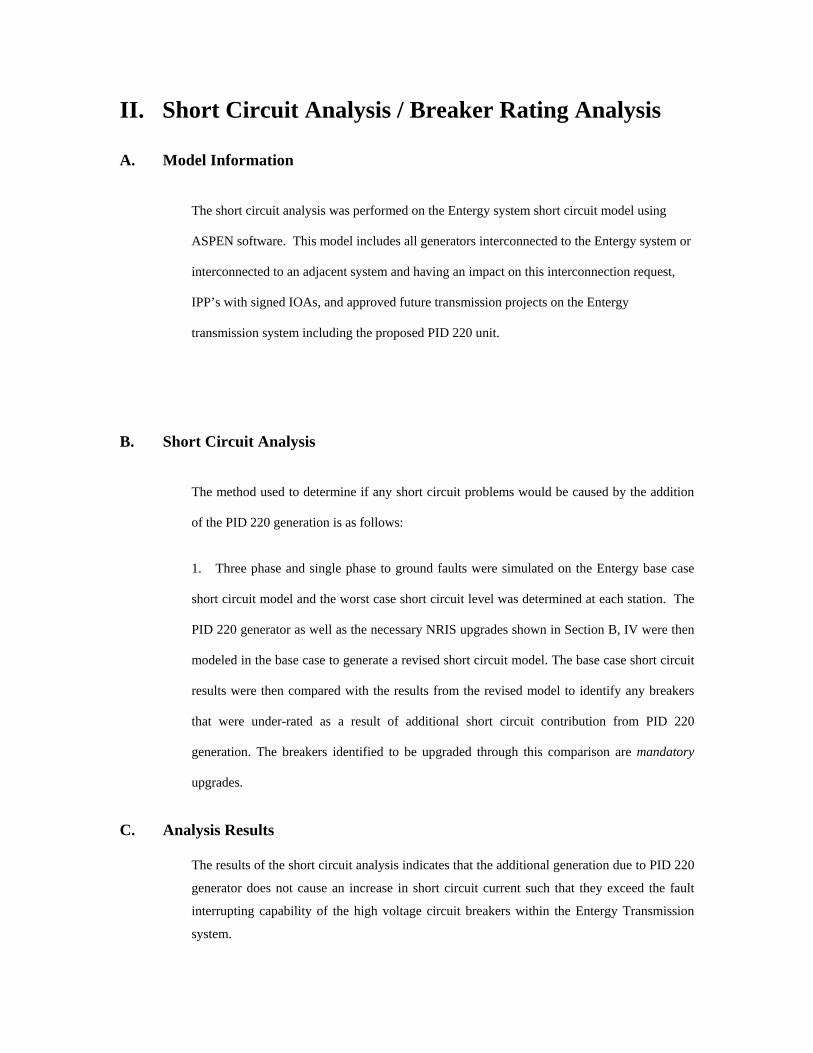
II. Short Circuit Analysis / Breaker Rating Analysis
A. Model Information
The short circuit analysis was performed on the Entergy system short circuit model using
ASPEN software. This model includes all generators interconnected to the Entergy system or
interconnected to an adjacent system and having an impact on this interconnection request,
IPP’s with signed IOAs, and approved future transmission projects on the Entergy
transmission system including the proposed PID 220 unit.
B. Short Circuit Analysis
The method used to determine if any short circuit problems would be caused by the addition
of the PID 220 generation is as follows:
1. Three phase and single phase to ground faults were simulated on the Entergy base case
short circuit model and the worst case short circuit level was determined at each station. The
PID 220 generator as well as the necessary NRIS upgrades shown in Section B, IV were then
modeled in the base case to generate a revised short circuit model. The base case short circuit
results were then compared with the results from the revised model to identify any breakers
that were under-rated as a result of additional short circuit contribution from PID 220
generation. The breakers identified to be upgraded through this comparison are mandatory
upgrades.
C. Analysis Results
The results of the short circuit analysis indicates that the additional generation due to PID 220
generator does not cause an increase in short circuit current such that they exceed the fault
interrupting capability of the high voltage circuit breakers within the Entergy Transmission
system.
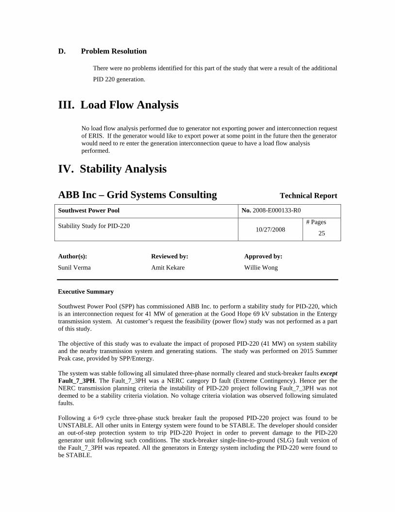
D. Problem Resolution
There were no problems identified for this part of the study that were a result of the additional
PID 220 generation.
III. Load Flow Analysis
No load flow analysis performed due to generator not exporting power and interconnection request of ERIS. If the generator would like to export power at some point in the future then the generator would need to re enter the generation interconnection queue to have a load flow analysis performed.
IV. Stability Analysis
ABB Inc – Grid Systems Consulting Technical Report
Southwest Power Pool No. 2008-E000133-R0
Stability Study for PID-220 10/27/2008
# Pages
25
Author(s): Reviewed by: Approved by:
Sunil Verma Amit Kekare Willie Wong Executive Summary Southwest Power Pool (SPP) has commissioned ABB Inc. to perform a stability study for PID-220, which is an interconnection request for 41 MW of generation at the Good Hope 69 kV substation in the Entergy transmission system. At customer’s request the feasibility (power flow) study was not performed as a part of this study. The objective of this study was to evaluate the impact of proposed PID-220 (41 MW) on system stability and the nearby transmission system and generating stations. The study was performed on 2015 Summer Peak case, provided by SPP/Entergy. The system was stable following all simulated three-phase normally cleared and stuck-breaker faults except Fault_7_3PH. The Fault_7_3PH was a NERC category D fault (Extreme Contingency). Hence per the NERC transmission planning criteria the instability of PID-220 project following Fault_7_3PH was not deemed to be a stability criteria violation. No voltage criteria violation was observed following simulated faults. Following a 6+9 cycle three-phase stuck breaker fault the proposed PID-220 project was found to be UNSTABLE. All other units in Entergy system were found to be STABLE. The developer should consider an out-of-step protection system to trip PID-220 Project in order to prevent damage to the PID-220 generator unit following such conditions. The stuck-breaker single-line-to-ground (SLG) fault version of the Fault_7_3PH was repeated. All the generators in Entergy system including the PID-220 were found to be STABLE.

Based on the results of stability analysis it can be concluded that interconnection of the proposed
PID-220 (41 MW) generation at the Good Hope 69 kV bus does not adversely impact the stability of the Entergy System in the local area.
The results of this analysis are based on available data and assumptions made at the time of conducting this study. If any of the data and/or assumptions made in developing the study model change, the results provided in this report may not apply.
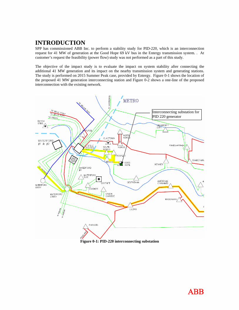
INTRODUCTION SPP has commissioned ABB Inc. to perform a stability study for PID-220, which is an interconnection request for 41 MW of generation at the Good Hope 69 kV bus in the Entergy transmission system. . At customer’s request the feasibility (power flow) study was not performed as a part of this study. The objective of the impact study is to evaluate the impact on system stability after connecting the additional 41 MW generation and its impact on the nearby transmission system and generating stations. The study is performed on 2015 Summer Peak case, provided by Entergy. Figure 0-1 shows the location of the proposed 41 MW generation interconnecting station and Figure 0-2 shows a one-line of the proposed interconnection with the existing network.
Interconnecting substation for PID 220 generator
Figure 0-1: PID-220 interconnecting substation
ΑΒΒ
G
PROSPECT 230 kV
S4799
S8206
S7726
T
HARAHAN 230 kV
GOOD HOPE230 kV
KENNER 230 kV
DESTRENAN230 kV
TO AVONDALE
NINE MILE PT
LOAD
13.8 kV
GOOD HOPE69 kV
TR #1
TR #2 TR #4
TR #1
TR #4
TR #2
A B
D C
TR #3
S6404
S8272 S3930
S4824
S6601
S6430
S6455
S6403
TR #3
Load transfer to PID-220 Bus
PID-220
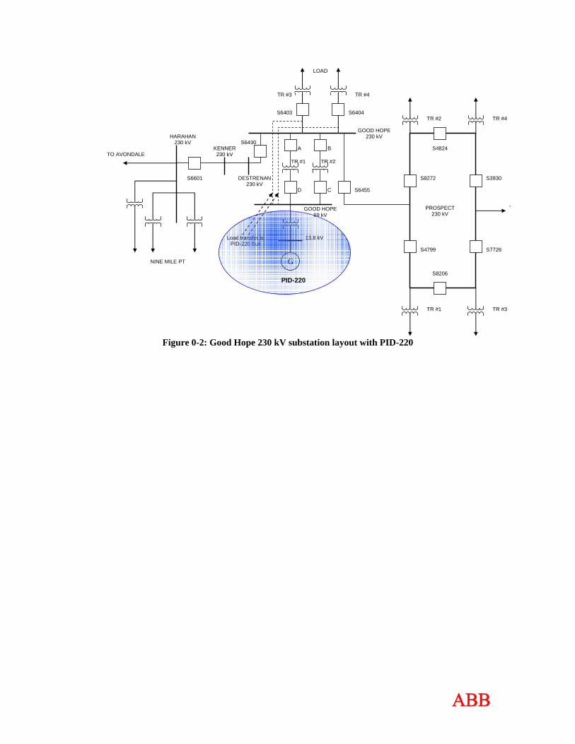
Figure 0-2: Good Hope 230 kV substation layout with PID-220
ΑΒΒ
STABILITY ANALYSIS Stability Analysis Methodology Using Planning Standards approved by NERC, the following stability definition was applied in the Transient Stability Analysis: “Power system stability is defined as that condition in which the differences of the angular positions of synchronous machine rotors become constant following an aperiodic system disturbance.” Stability analysis was performed using Siemens-PTI’s PSS/ETM dynamics program V30.3.2. Three-phase and single-phase line faults were simulated for the specified durations and the synchronous machine rotor angles were monitored to make sure they maintained synchronism following the fault removal. All the breakers at Good Hope 230 kV substation are assumed to be common trip breakers. Based on the Entergy study criteria, three-phase faults with normal clearing and delayed clearing were simulated. The stability analysis was performed using the PSS/E dynamics program, which only simulates the positive sequence network. Unbalanced faults involve the positive, negative, and zero sequence networks. For unbalanced faults, the equivalent fault admittance must be inserted in the PSS/E positive sequence model between the faulted bus and ground to simulate the effect of the negative and zero sequence networks. For a single-line-to-ground (SLG) fault, the fault admittance equals the inverse of the sum of the positive, negative and zero sequence Thevenin impedances at the faulted bus. Since PSS/E inherently models the positive sequence fault impedance, the sum of the negative and zero sequence Thevenin impedances needs to be added and entered as the fault impedance at the faulted bus. For three-phase faults, a fault admittance of –j2E9 is used (essentially infinite admittance or zero impedance).
ΑΒΒ
ΑΒΒ
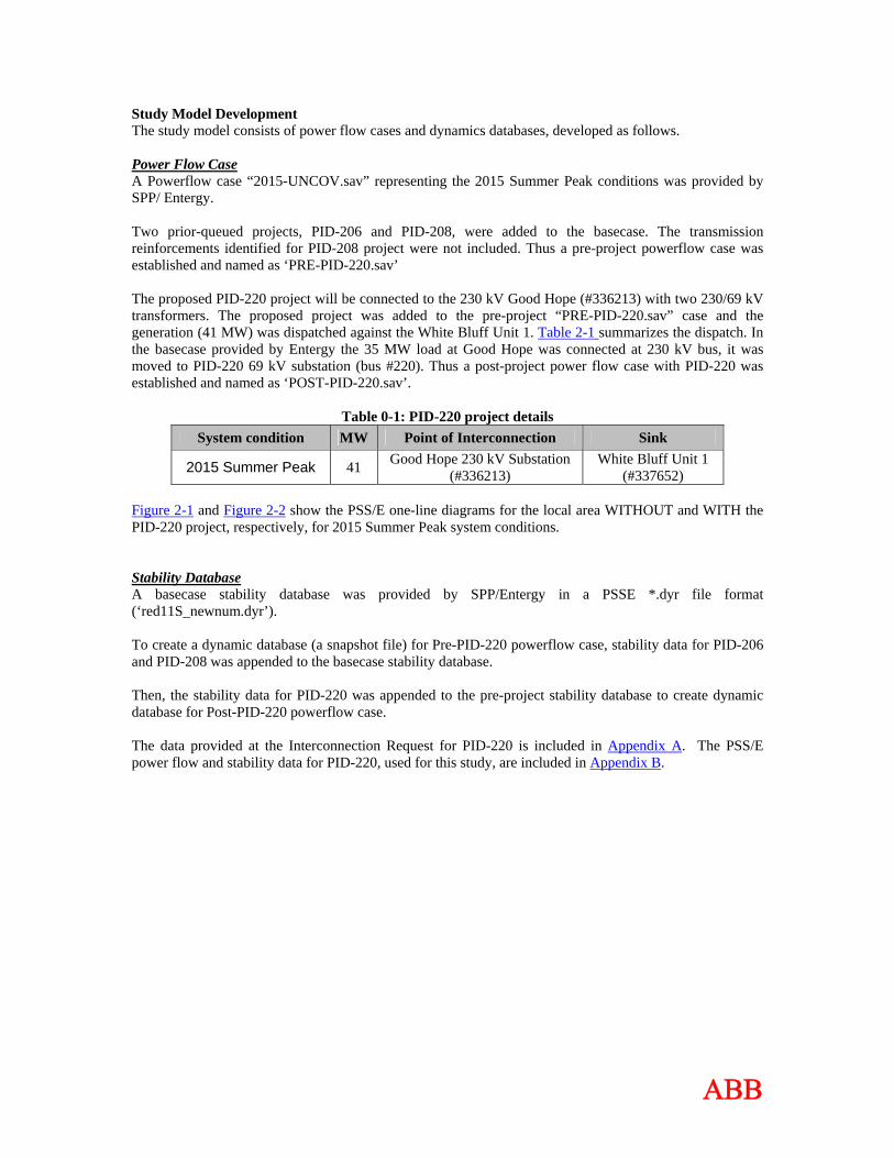
Study Model Development The study model consists of power flow cases and dynamics databases, developed as follows. Power Flow Case A Powerflow case “2015-UNCOV.sav” representing the 2015 Summer Peak conditions was provided by SPP/ Entergy. Two prior-queued projects, PID-206 and PID-208, were added to the basecase. The transmission reinforcements identified for PID-208 project were not included. Thus a pre-project powerflow case was established and named as ‘PRE-PID-220.sav’ The proposed PID-220 project will be connected to the 230 kV Good Hope (#336213) with two 230/69 kV transformers. The proposed project was added to the pre-project “PRE-PID-220.sav” case and the generation (41 MW) was dispatched against the White Bluff Unit 1. Table 2-1 summarizes the dispatch. In the basecase provided by Entergy the 35 MW load at Good Hope was connected at 230 kV bus, it was moved to PID-220 69 kV substation (bus #220). Thus a post-project power flow case with PID-220 was established and named as ‘POST-PID-220.sav’.
Table 0-1: PID-220 project details System condition MW Point of Interconnection Sink
2015 Summer Peak 41 Good Hope 230 kV Substation (#336213)
White Bluff Unit 1 (#337652)
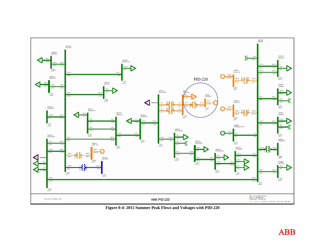
Figure 2-1 and Figure 2-2 show the PSS/E one-line diagrams for the local area WITHOUT and WITH the PID-220 project, respectively, for 2015 Summer Peak system conditions. Stability Database A basecase stability database was provided by SPP/Entergy in a PSSE *.dyr file format (‘red11S_newnum.dyr’). To create a dynamic database (a snapshot file) for Pre-PID-220 powerflow case, stability data for PID-206 and PID-208 was appended to the basecase stability database. Then, the stability data for PID-220 was appended to the pre-project stability database to create dynamic database for Post-PID-220 powerflow case. The data provided at the Interconnection Request for PID-220 is included in Appendix A. The PSS/E power flow and stability data for PID-220, used for this study, are included in Appendix B.
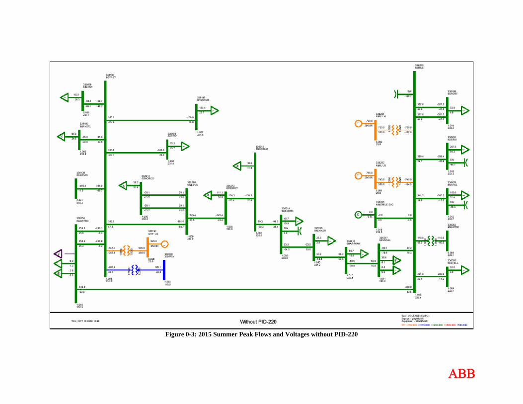
Figure 0-3: 2015 Summer Peak Flows and Voltages without PID-220
ΑΒΒ
ΑΒΒ
Figure 0-4: 2015 Summer Peak Flows and Voltages with PID-220
PID-220
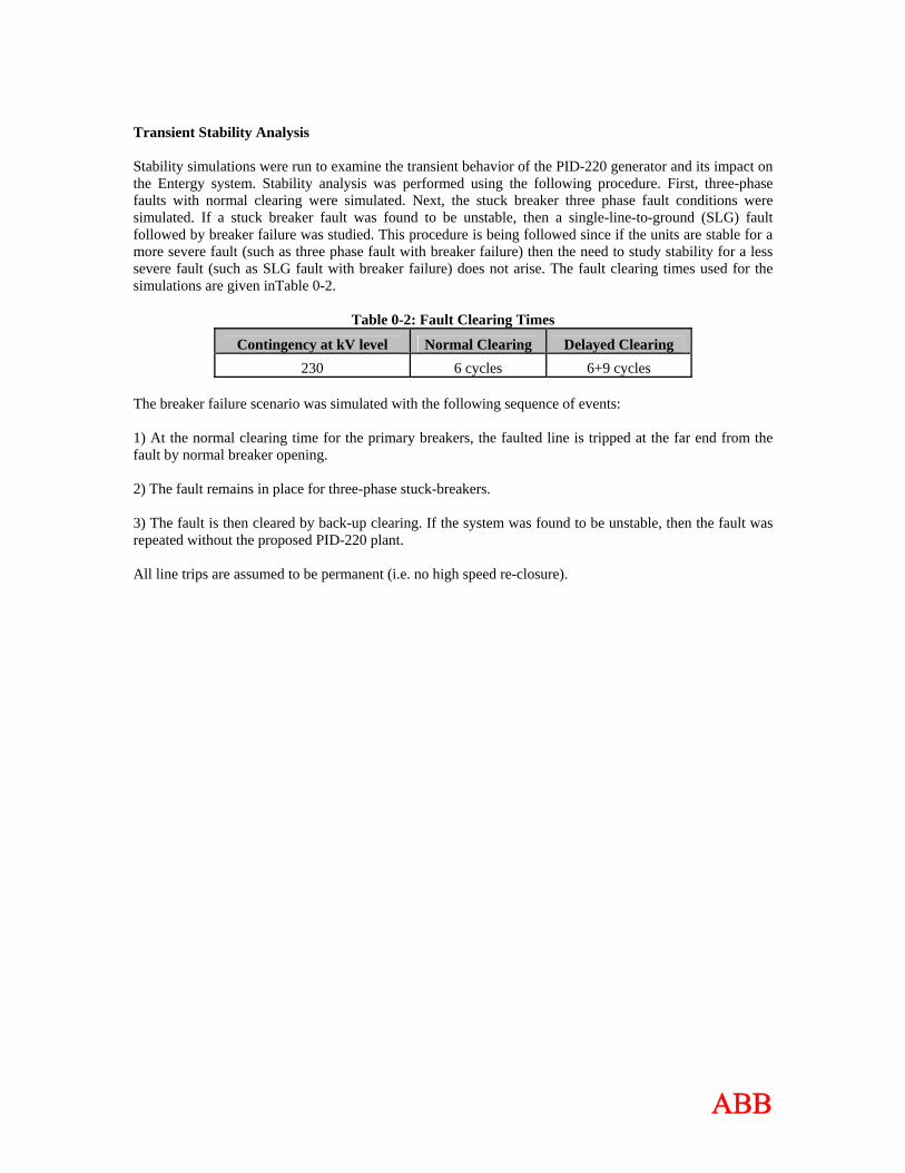
Transient Stability Analysis Stability simulations were run to examine the transient behavior of the PID-220 generator and its impact on the Entergy system. Stability analysis was performed using the following procedure. First, three-phase faults with normal clearing were simulated. Next, the stuck breaker three phase fault conditions were simulated. If a stuck breaker fault was found to be unstable, then a single-line-to-ground (SLG) fault followed by breaker failure was studied. This procedure is being followed since if the units are stable for a more severe fault (such as three phase fault with breaker failure) then the need to study stability for a less severe fault (such as SLG fault with breaker failure) does not arise. The fault clearing times used for the simulations are given inTable 0-2.
Table 0-2: Fault Clearing Times
Contingency at kV level Normal Clearing Delayed Clearing 230 6 cycles 6+9 cycles
The breaker failure scenario was simulated with the following sequence of events: 1) At the normal clearing time for the primary breakers, the faulted line is tripped at the far end from the fault by normal breaker opening. 2) The fault remains in place for three-phase stuck-breakers. 3) The fault is then cleared by back-up clearing. If the system was found to be unstable, then the fault was repeated without the proposed PID-220 plant. All line trips are assumed to be permanent (i.e. no high speed re-closure).
ΑΒΒ

ΑΒΒ
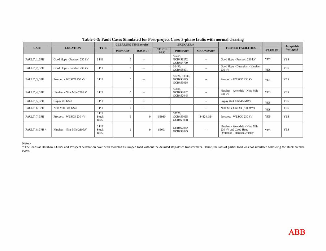
Table 0-3 lists all the fault cases that were simulated in this study. Fault scenarios were formulated by examining the system configuration shown in Figure 0-2. FLT_1_3PH to FLT_6_3PH represent the normally cleared 3-phase faults. FLT_7_3PH and FLT_8_3PH Faults represent the 3-phase stuck breaker faults. For all cases analyzed, the initial disturbance was applied at t = 0.1 seconds. The breaker clearing was applied at the appropriate time following this fault inception.
ΑΒΒ
Table 0-3: Fault Cases Simulated for Post-project Case: 3-phase faults with normal clearing CLEARING TIME (cycles) BREKAER #
CASE LOCATION TYPE PRIMARY BACKUP STUCK
BRK PRIMARY SECONDARY TRIPPED FACILITIES
STABLE? Acceptable Voltages?
FAULT_1_3PH Good Hope - Prospect 230 kV 3 PH 6 -- S6455, GCB#S8272, GCB#S4799
-- Good Hope - Prospect 230 kV YES YES
FAULT_2_3PH Good Hope - Harahan 230 kV 3 PH 6 -- S6430, GCB#S8801 -- Good Hope - Destrehan - Harahan
230 kV YES YES
FAULT_3_3PH Prospect - WESCO 230 kV 3 PH 6 -- S7726, S3930, GCB#S3095, GCB#S3098
-- Prospect - WESCO 230 kV
YES YES
FAULT_4_3PH Harahan - Nine Mile 230 kV 3 PH 6 -- S6601, GCB#S2042, GCB#S2045
-- Harahan - Avondale - Nine Mile 230 kV
YES YES
FAULT_5_3PH Gypsy U3 GSU 3 PH 6 -- -- Gypsy Unit #3 (545 MW) YES YES
FAULT_6_3PH Nine Mile U4 GSU 3 PH 6 -- -- Nine Mile Unit #4 (730 MW) YES YES
FAULT_7_3PH Prospect - WESCO 230 kV 3 PH Stuck BRK
6 9 S3930 S7726, GCB#S3095, GCB#S3098
S4824, M4 Prospect - WESCO 230 kV YES YES
FAULT_8_3PH * Harahan - Nine Mile 230 kV 3 PH Stuck BRK
6 9 S6601 GCB#S2042, GCB#S2045 --
Harahan - Avondale - Nine Mile 230 kV and Good Hope - Destrehan - Harahan 230 kV
YES YES
Note:- * The loads at Harahan 230 kV and Prospect Substation have been modeled as lumped load without the detailed step-down transformers. Hence, the loss of partial load was not simulated following the stuck breaker event.
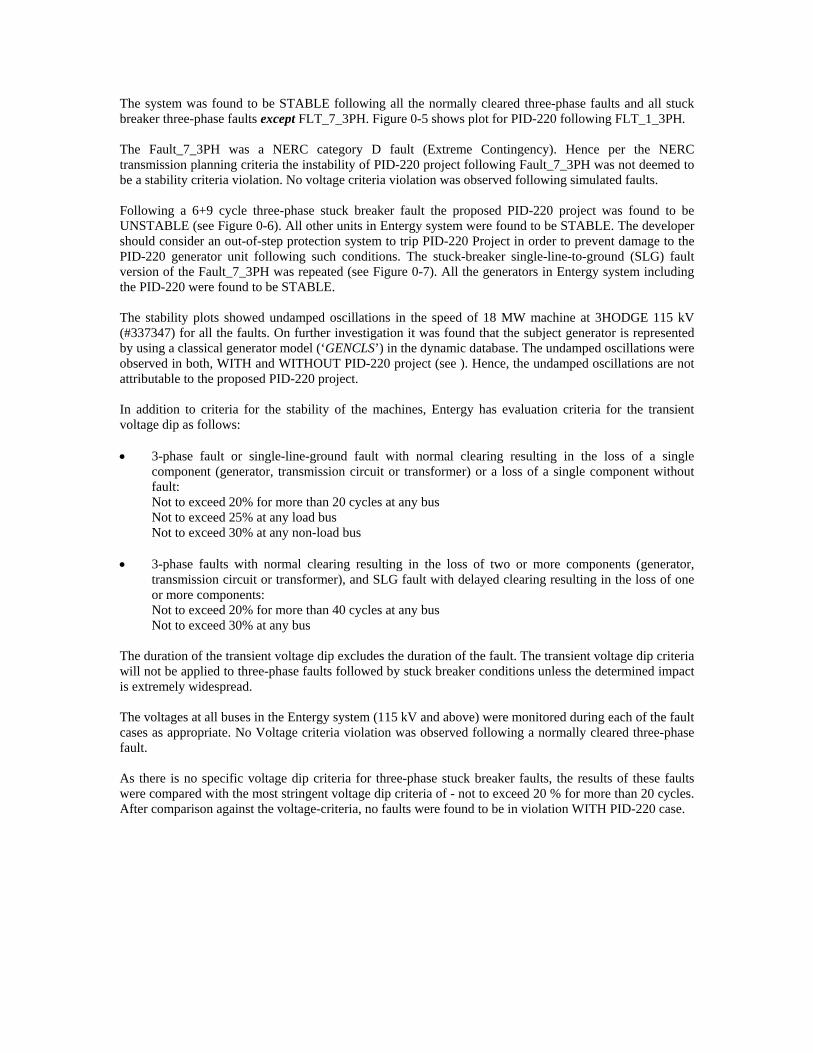
The system was found to be STABLE following all the normally cleared three-phase faults and all stuck breaker three-phase faults except FLT_7_3PH. Figure 0-5 shows plot for PID-220 following FLT_1_3PH. The Fault_7_3PH was a NERC category D fault (Extreme Contingency). Hence per the NERC transmission planning criteria the instability of PID-220 project following Fault_7_3PH was not deemed to be a stability criteria violation. No voltage criteria violation was observed following simulated faults. Following a 6+9 cycle three-phase stuck breaker fault the proposed PID-220 project was found to be UNSTABLE (see Figure 0-6). All other units in Entergy system were found to be STABLE. The developer should consider an out-of-step protection system to trip PID-220 Project in order to prevent damage to the PID-220 generator unit following such conditions. The stuck-breaker single-line-to-ground (SLG) fault version of the Fault_7_3PH was repeated (see Figure 0-7). All the generators in Entergy system including the PID-220 were found to be STABLE. The stability plots showed undamped oscillations in the speed of 18 MW machine at 3HODGE 115 kV (#337347) for all the faults. On further investigation it was found that the subject generator is represented by using a classical generator model (‘GENCLS’) in the dynamic database. The undamped oscillations were observed in both, WITH and WITHOUT PID-220 project (see ). Hence, the undamped oscillations are not attributable to the proposed PID-220 project. In addition to criteria for the stability of the machines, Entergy has evaluation criteria for the transient voltage dip as follows: • 3-phase fault or single-line-ground fault with normal clearing resulting in the loss of a single
component (generator, transmission circuit or transformer) or a loss of a single component without fault: Not to exceed 20% for more than 20 cycles at any bus Not to exceed 25% at any load bus Not to exceed 30% at any non-load bus
• 3-phase faults with normal clearing resulting in the loss of two or more components (generator, transmission circuit or transformer), and SLG fault with delayed clearing resulting in the loss of one or more components: Not to exceed 20% for more than 40 cycles at any bus Not to exceed 30% at any bus
The duration of the transient voltage dip excludes the duration of the fault. The transient voltage dip criteria will not be applied to three-phase faults followed by stuck breaker conditions unless the determined impact is extremely widespread. The voltages at all buses in the Entergy system (115 kV and above) were monitored during each of the fault cases as appropriate. No Voltage criteria violation was observed following a normally cleared three-phase fault. As there is no specific voltage dip criteria for three-phase stuck breaker faults, the results of these faults were compared with the most stringent voltage dip criteria of - not to exceed 20 % for more than 20 cycles. After comparison against the voltage-criteria, no faults were found to be in violation WITH PID-220 case.
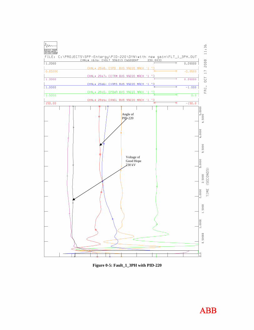
Figure 0-5: Fault_1_3PH with PID-220
Voltage of Good Hope 230 kV
Angle of PID-220
ΑΒΒ

Figure 0-6: Fault_7_3PH with PID-220
Angle of PID-220
ΑΒΒ
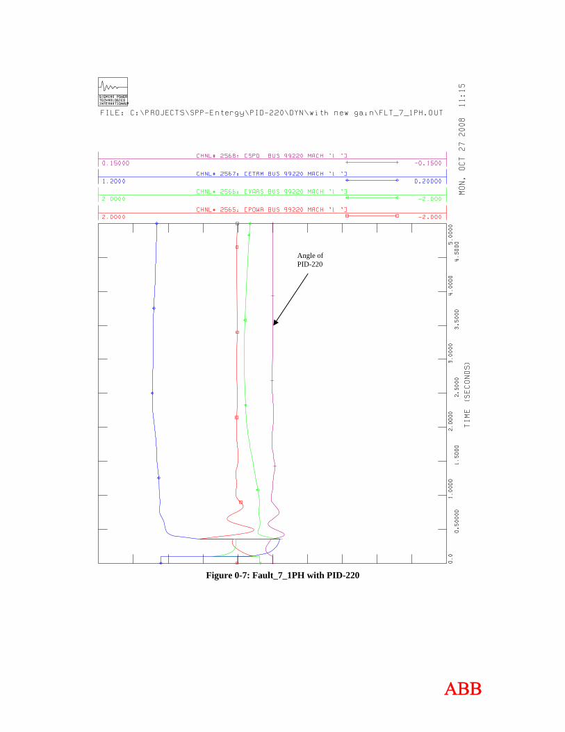
Figure 0-7: Fault_7_1PH with PID-220
Angle of PID-220
ΑΒΒ
Figure 0-8: Fault_1_3PH without and with PID-220
Speed of machine at #337347
ΑΒΒ
CONCLUSIONS The objective of this study was to evaluate the impact of proposed PID-220 (41 MW) on system stability and the nearby transmission system and generating stations. The study was performed on 2015 Summer Peak case, provided by SPP/Entergy. The system was stable following all simulated three-phase normally cleared and stuck-breaker faults except Fault_7_3PH. The Fault_7_3PH was a NERC category D fault (Extreme Contingency). Hence per the NERC transmission planning criteria the instability of PID-220 project following Fault_7_3PH was not deemed to be a stability criteria violation. No voltage criteria violation was observed following simulated faults. Following a 6+9 cycle three-phase stuck breaker fault the proposed PID-220 project was found to be UNSTABLE. All other units in Entergy system were found to be STABLE. The developer should consider an out-of-step protection system to trip PID-220 Project in order to prevent damage to the PID-220 generator unit following such conditions. The stuck-breaker single-line-to-ground (SLG) fault version of the Fault_7_3PH was repeated. All the generators in Entergy system including the PID-220 were found to be STABLE.
Based on the results of stability analysis it can be concluded that interconnection of the proposed PID-220 (41 MW) generation at the Good Hope 69 kV bus does not adversely impact the stability of the Entergy System in the local area.
The results of this analysis are based on available data and assumptions made at the time of conducting this study. If any of the data and/or assumptions made in developing the study model change, the results provided in this report may not apply.
ΑΒΒ
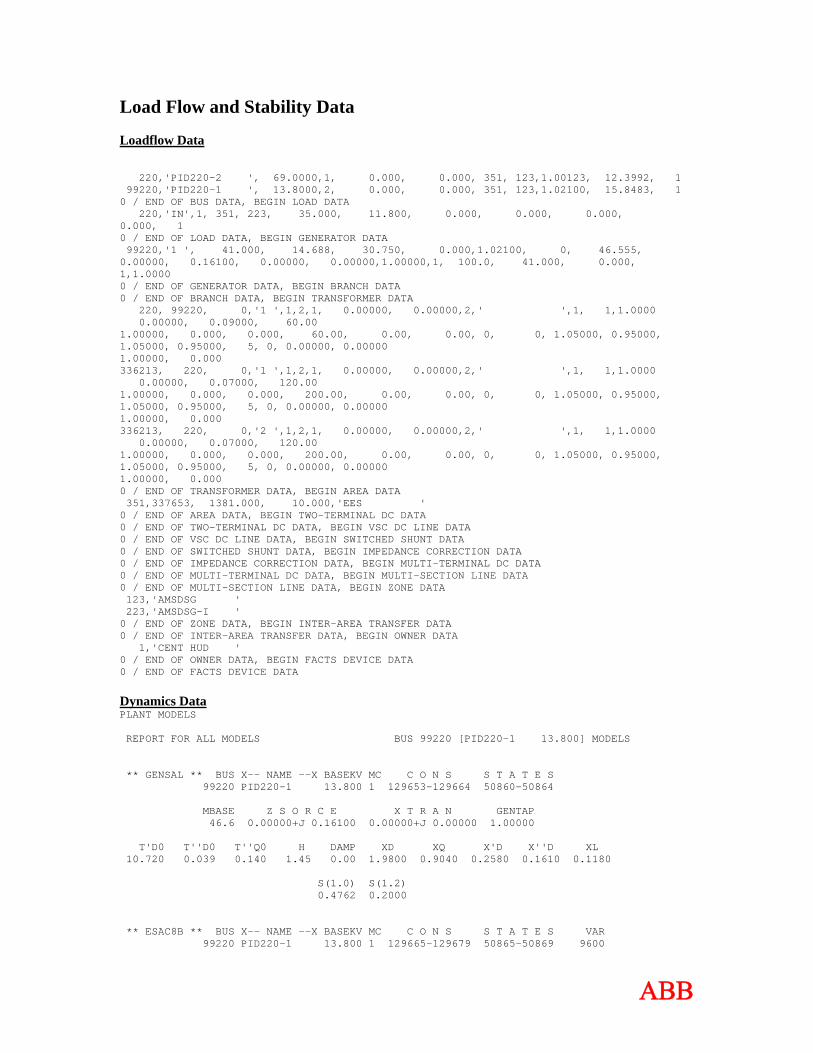
Load Flow and Stability Data Loadflow Data 220,'PID220-2 ', 69.0000,1, 0.000, 0.000, 351, 123,1.00123, 12.3992, 1 99220,'PID220-1 ', 13.8000,2, 0.000, 0.000, 351, 123,1.02100, 15.8483, 1 0 / END OF BUS DATA, BEGIN LOAD DATA 220,'IN',1, 351, 223, 35.000, 11.800, 0.000, 0.000, 0.000, 0.000, 1 0 / END OF LOAD DATA, BEGIN GENERATOR DATA 99220,'1 ', 41.000, 14.688, 30.750, 0.000,1.02100, 0, 46.555, 0.00000, 0.16100, 0.00000, 0.00000,1.00000,1, 100.0, 41.000, 0.000, 1,1.0000 0 / END OF GENERATOR DATA, BEGIN BRANCH DATA 0 / END OF BRANCH DATA, BEGIN TRANSFORMER DATA 220, 99220, 0,'1 ',1,2,1, 0.00000, 0.00000,2,' ',1, 1,1.0000 0.00000, 0.09000, 60.00 1.00000, 0.000, 0.000, 60.00, 0.00, 0.00, 0, 0, 1.05000, 0.95000, 1.05000, 0.95000, 5, 0, 0.00000, 0.00000 1.00000, 0.000 336213, 220, 0,'1 ',1,2,1, 0.00000, 0.00000,2,' ',1, 1,1.0000 0.00000, 0.07000, 120.00 1.00000, 0.000, 0.000, 200.00, 0.00, 0.00, 0, 0, 1.05000, 0.95000, 1.05000, 0.95000, 5, 0, 0.00000, 0.00000 1.00000, 0.000 336213, 220, 0,'2 ',1,2,1, 0.00000, 0.00000,2,' ',1, 1,1.0000 0.00000, 0.07000, 120.00 1.00000, 0.000, 0.000, 200.00, 0.00, 0.00, 0, 0, 1.05000, 0.95000, 1.05000, 0.95000, 5, 0, 0.00000, 0.00000 1.00000, 0.000 0 / END OF TRANSFORMER DATA, BEGIN AREA DATA 351,337653, 1381.000, 10.000,'EES ' 0 / END OF AREA DATA, BEGIN TWO-TERMINAL DC DATA 0 / END OF TWO-TERMINAL DC DATA, BEGIN VSC DC LINE DATA 0 / END OF VSC DC LINE DATA, BEGIN SWITCHED SHUNT DATA 0 / END OF SWITCHED SHUNT DATA, BEGIN IMPEDANCE CORRECTION DATA 0 / END OF IMPEDANCE CORRECTION DATA, BEGIN MULTI-TERMINAL DC DATA 0 / END OF MULTI-TERMINAL DC DATA, BEGIN MULTI-SECTION LINE DATA 0 / END OF MULTI-SECTION LINE DATA, BEGIN ZONE DATA 123,'AMSDSG ' 223,'AMSDSG-I ' 0 / END OF ZONE DATA, BEGIN INTER-AREA TRANSFER DATA 0 / END OF INTER-AREA TRANSFER DATA, BEGIN OWNER DATA 1,'CENT HUD ' 0 / END OF OWNER DATA, BEGIN FACTS DEVICE DATA 0 / END OF FACTS DEVICE DATA Dynamics Data PLANT MODELS REPORT FOR ALL MODELS BUS 99220 [PID220-1 13.800] MODELS ** GENSAL ** BUS X-- NAME --X BASEKV MC C O N S S T A T E S 99220 PID220-1 13.800 1 129653-129664 50860-50864 MBASE Z S O R C E X T R A N GENTAP 46.6 0.00000+J 0.16100 0.00000+J 0.00000 1.00000 T'D0 T''D0 T''Q0 H DAMP XD XQ X'D X''D XL 10.720 0.039 0.140 1.45 0.00 1.9800 0.9040 0.2580 0.1610 0.1180 S(1.0) S(1.2) 0.4762 0.2000 ** ESAC8B ** BUS X-- NAME --X BASEKV MC C O N S S T A T E S VAR 99220 PID220-1 13.800 1 129665-129679 50865-50869 9600
ΑΒΒ
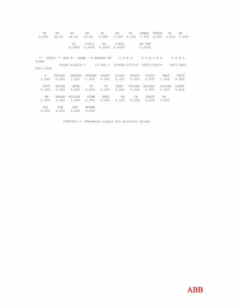
TR KP KI KD TD KA TA VRMAX VRMIN TE KE 0.005 50.00 28.00 19.00 0.080 1.000 0.000 7.300 0.000 0.410 1.000 E1 S(E1) E2 S(E2) KE VAR 6.5000 0.3000 9.0000 3.0000 0.0000 ** GGOV1 ** BUS X-- NAME --X BASEKV MC C O N S S T A T E S V A R S ICONS 99220 PID220-1 13.800 1 129680-129712 50870-50879 9601-9620 5957-5958 R TPELEC MAXERR MINERR KPGOV KIGOV KDGOV TDGOV VMAX VMIN 0.040 0.200 1.000 -1.000 4.000 0.067 0.000 0.000 1.000 0.000 TACT KTURB WFNL TB TC TENG TFLOAD KPLOAD KILOAD LDREF 0.200 0.000 0.000 0.000 0.000 0.000 0.000 0.000 0.000 0.000 DM ROPEN RCLOSE KIMW ASET KA TA TRATE DB 0.000 3.000 3.000 0.000 0.000 0.000 0.000 0.000 0.000 TSA TSB RUP RDOWN 0.000 0.000 0.000 0.000 ICON(M)=-1 (Feedback signal for governor droop)
ΑΒΒ
Related Documents