System bus

System bus. Overview Computer components The von Neumann architecture is based on three key concepts: Data and instructions are stored in a single read-
Dec 31, 2015
Welcome message from author
This document is posted to help you gain knowledge. Please leave a comment to let me know what you think about it! Share it to your friends and learn new things together.
Transcript
System bus

Overview
Computer components

The von Neumann architecture is based on
three key concepts:• Data and instructions are stored in a single read-
write memory
• The contents of this memory are addressable by location, without regard to the type of data contained there
• Execution occurs in a sequential fashion (unless explicitly modified) from one instruction to the next

Two approaches to programming
• Hardwired programming• Software

Other components needed
• I/O Components• Main memory

Interactions among Computer Components
• Memory Address Register• Memory Buffer Register • I/O address register• I/O buffer register• Memory module

Computer Function
• Processing required for a single instruction is called an instruction cycle
• Simple POV (Point-Of-View): 2 steps– Fetch– Execute
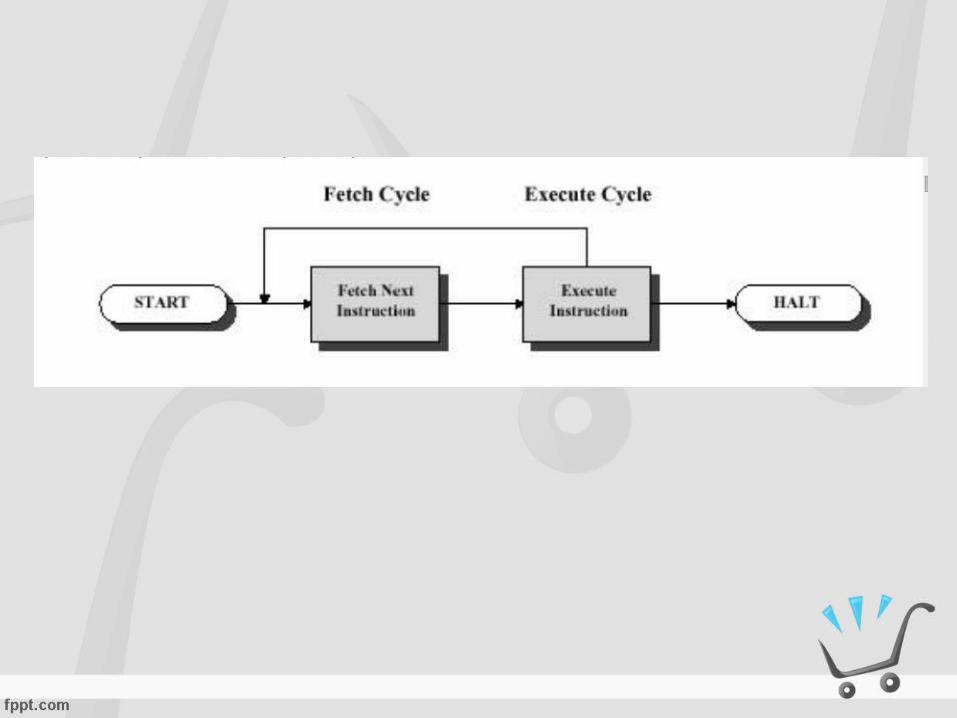

Fetch
• Program counter (PC) register keeps track of which instruction executes next
• Normally, CPU increments PC after each fetch
• Fetched instruction is loaded into the instruction register (IR)

Execute
• May involve several operations• May utilize previously changed state of CPU and
(indirectly) other devices• General categories:
– CPU-Memory: Data may be transferred from CPU to memory or vice-versa
– CPU-IO: Data may be transferred between CPU and an I/O module
– Data Processing: CPU may perform some arithmetic or logic operation on the data
– Control: An instruction may specify that the sequence of execution be altered

More complex instructions
• May combine these categories
• May perform more than one reference to memory
• May specify I/O operation instead of memory reference
• May specify an operation to be performed on a vector of numbers or a string of characters

Expanded execution cycle
• Instruction Address Calculation• Instruction Fetch• Instruction Operation Decoding• Operand Address Calculation• Operand Fetch• Data Operation• Operand Store

Interrupts
• Mechanism by which other modules may interrupt the normal processing of the CPU
• Classes– Program - as a result of program execution– Timer - generated by hardware timer– I/O - to signal completion of I/O or error– Hardware failure

Instruction cycle with interrupts

When an interrupt signal is generated, the
processor:• Suspends execution of the current
program and saves its context
• Sets PC to starting address of an interrupt handler routine
Multiple interrupts
• Can be handled by disabling some or all interrupts. Disabled interrupts generally remain pending and are handled sequentially
• Can be handled by prioritizing interrupts, allowing a higher priority interrupt to interrupt one of lower priority

Physical Interrupts
• Interrupts are represented as one or more lines in the system bus
– One line• Polling
– Multiple lines• Addressable interrupts

Interconnection Structures
• The collection of paths connecting the various modules of a computer (CPU, memory, I/O) is called the interconnection structure.

Memory
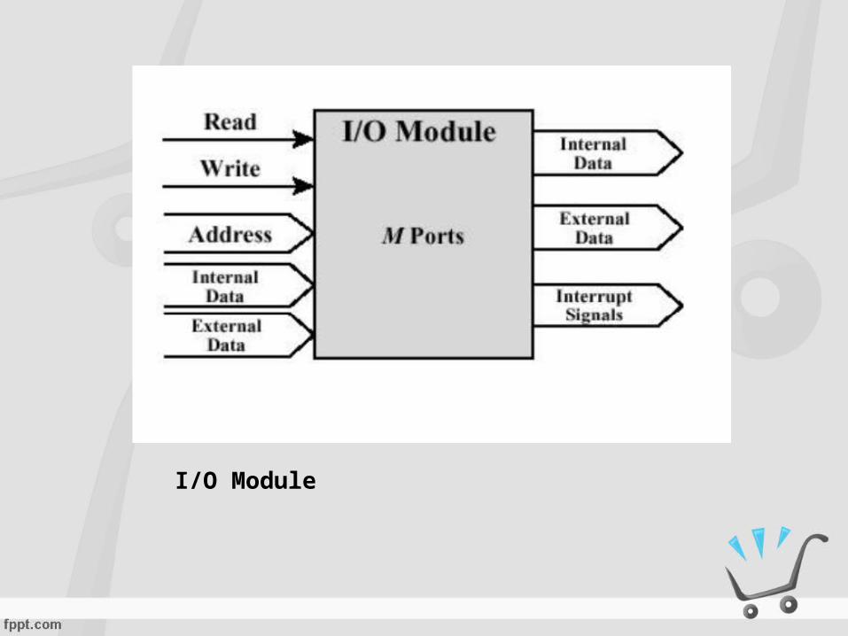
I/O Module

CPU

It must support the following types of transfers
• Memory to CPU
• CPU to Memory
• I/O to CPU
• CPU to I/O
• I/O to or from Memory - using Direct Memory Access (DMA)

Bus Interconnection
• A bus is a shared transmission medium– Must only be used by one device at a
time– When used to connect major computer
components (CPU, memory, I/O) is called a system bus

System busData busAddress busControl bus
Three functional groups of communication lines
• Data bus• Address bus• Control bus

• If one module wishes to send data to another?
• If one module wishes to request data from another?

Typical physical arrangement of a system
bus• A number of parallel electrical conductors
• Each system component taps into some or all of the bus lines
• System can be expanded by adding more boards
• A bad component can be replaced by replacing the board where it resides

Multiple Bus Hierarchies
• A great number of devices on a bus will cause performance to suffer– Propagation delay– Bottleneck

Traditional Hierarchical Bus Architecture

High-performance Hierarchical Bus Architecture

Elements of Bus Design
• Bus Types• Physical dedication• Method of Arbitration• Timing• Bus Width• Data Transfer Type• Combination operations• Block data transfer
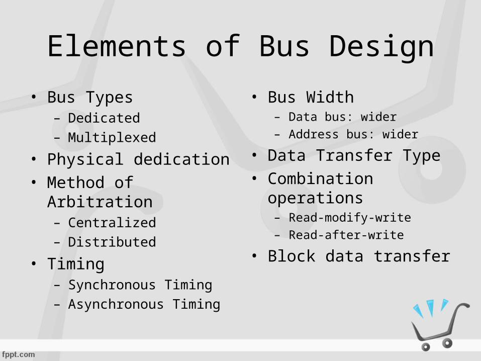
Elements of Bus Design
• Bus Types– Dedicated– Multiplexed
• Physical dedication• Method of Arbitration
– Centralized– Distributed
• Timing– Synchronous Timing– Asynchronous Timing
• Bus Width– Data bus: wider– Address bus: wider
• Data Transfer Type• Combination
operations– Read-modify-write– Read-after-write
• Block data transfer


PCI
• PCI=Peripheral Component Interconnect
– High-bandwidth– Processor independent– Can function as a mezzanine or
peripheral bus
Related Documents