Synthesis, characterization, and hydrogen storage capacities of hierarchical porous carbide derived carbon monolith† Jiacheng Wang, Martin Oschatz, Tim Biemelt, Lars Borchardt, Irena Senkovska, Martin R. Lohe and Stefan Kaskel * Received 9th July 2012, Accepted 26th September 2012 DOI: 10.1039/c2jm34472f Hierarchical porous carbide-derived carbon monoliths (HPCDCM) were prepared by selective extraction of silicon from ordered mesoporous silicon carbide monoliths (OMSCM) through chlorination at high temperature. The OMSCM was firstly synthesized by pressure-assisted nanocasting procedure using KIT-6 silica as the hard template and polycarbosilane (PCS-800) as the preceramic precursor. The OMSCM showed cubic ordered mesoporous structure with specific surface area of over 600 m 2 g 1 . After the chlorination, the resulting HPCDCM demonstrated very high specific surface area (2933 m 2 g 1 ), large pore volume (2.101 cm 3 g 1 ) with large volume of micropores (0.981 cm 3 g 1 ), and narrow dual pore size distributions (micropore: 0.9 nm, and mesopore: 3.1 nm). Macropores in the micron range were observed in the HPCDCM. The mesostructural ordering was not maintained in the HPCDCM and the volume of the HPCDCM had greatly shrunk, by 21.2% compared to that of the OMSCM, but the tablet-like appearance was well retained in the HPCDCM. At 196 C, the HPCDCM shows good hydrogen uptakes of 2.4 wt% and 4.4 wt% at 1 bar and 36 bar, respectively. The calculated volumetric hydrogen storage capacity is 11.6 g L 1 at 36 bar. The gravimetric hydrogen uptake capacity of the HPCDCM is comparable to, or higher than, those of previously reported ordered mesoporous carbide-derived carbon (CDC) powder and microporous CDC powder. 1. Introduction Porous carbon materials with high surface areas and uniform pore size distributions have received increasing attention in various applications, such as gas adsorbents, 1–3 bioimaging, 4 catalytic supports, 5,6 the electrode materials in various electro- chemical devices, 7,8 etc., 9,10 because they have the significant advantages of wide availability, adjustable microstructure, low- cost, high chemical and thermal stability, and many variable forms. 11 Till now, much effort has been made to synthesize and tailor the microstructure of porous carbon materials by using various solid, liquid and gaseous precursors via various syntheses and activation procedures, such as the template method, 11 chemical activation, 12 physical activation, 12 etc. Templated porous carbons, normally synthesized using a ‘‘hard template’’ or ‘‘soft template’’ method, show well-controlled pore size distri- bution, and an interconnected pore structure. 11,13 Various chemical and physical activation procedures have been applied in industry to prepare activated carbons with high surface areas. 12,14 CDCs, prepared through the selective etching of metal carbides (e.g. SiC, TiC, and ZrC) using chlorine at high temperatures, have narrow pore size distributions, large pore volumes, and high surface areas of up to 3000 m 2 g 1 . 15,16 The reaction proceeds as shown in eqn (a). The metal element is removed in the form of gaseous MCl 4 , and solid carbon remains. The microstructure of the resulting CDC materials totally depends on both different metal carbide precursors and various chlorination parameters, such as temperature, time, etc. MC (s) + 2Cl 2 (g) / MCl 4 (g) + C (s) (a) Generally, the chlorination of various non-porous metal carbide precursors leads to microporous CDC materials with random pore orientation. 16–21 Microporous CDC materials exhibit great potential for hydrogen storage, 18,19 the electrode materials in supercapacitors, 16,20,22 and catalytic supports. 23,24 Introduction of uniform mesopores into CDC materials by a two-stage synthetic procedure resulted in bimodal micro-meso- porous CDCs in our group. Firstly, ordered mesoporous SiC was produced from liquid preceramic precursors (PCS-800 and SMPT-10) by the nanocasting method, in which various ordered mesoporous silicas (SBA-15 and KIT-6) were used as hard templates. 25,26 The ordered mesoporous SiC ceramics obtained were further transformed into ordered mesoporous CDC (OM-CDC) by chlorination at high temperatures. 27–31 OM-CDC Department of Inorganic Chemistry, Dresden University of Technology, Bergstrasse-66, 01069 Dresden, Germany. E-mail: Stefan.kaskel@ chemie.tu-dresden.de; Fax: +49 351 46337287; Tel: +49 351 46334885 † Electronic supplementary information (ESI) available. See DOI: 10.1039/c2jm34472f This journal is ª The Royal Society of Chemistry 2012 J. Mater. Chem., 2012, 22, 23893–23899 | 23893 Dynamic Article Links C < Journal of Materials Chemistry Cite this: J. Mater. Chem., 2012, 22, 23893 www.rsc.org/materials PAPER Downloaded by Cardiff University on 31 October 2012 Published on 26 September 2012 on http://pubs.rsc.org | doi:10.1039/C2JM34472F View Online / Journal Homepage / Table of Contents for this issue

Welcome message from author
This document is posted to help you gain knowledge. Please leave a comment to let me know what you think about it! Share it to your friends and learn new things together.
Transcript

Dynamic Article LinksC<Journal ofMaterials Chemistry
Cite this: J. Mater. Chem., 2012, 22, 23893
www.rsc.org/materials PAPER
Dow
nloa
ded
by C
ardi
ff U
nive
rsity
on
31 O
ctob
er 2
012
Publ
ishe
d on
26
Sept
embe
r 20
12 o
n ht
tp://
pubs
.rsc
.org
| do
i:10.
1039
/C2J
M34
472F
View Online / Journal Homepage / Table of Contents for this issue
Synthesis, characterization, and hydrogen storage capacities of hierarchicalporous carbide derived carbon monolith†
Jiacheng Wang, Martin Oschatz, Tim Biemelt, Lars Borchardt, Irena Senkovska, Martin R. Loheand Stefan Kaskel*
Received 9th July 2012, Accepted 26th September 2012
DOI: 10.1039/c2jm34472f
Hierarchical porous carbide-derived carbon monoliths (HPCDCM) were prepared by selective
extraction of silicon from ordered mesoporous silicon carbide monoliths (OMSCM) through
chlorination at high temperature. The OMSCM was firstly synthesized by pressure-assisted
nanocasting procedure using KIT-6 silica as the hard template and polycarbosilane (PCS-800) as the
preceramic precursor. The OMSCM showed cubic ordered mesoporous structure with specific surface
area of over 600 m2 g�1. After the chlorination, the resulting HPCDCM demonstrated very high
specific surface area (2933 m2 g�1), large pore volume (2.101 cm3 g�1) with large volume of micropores
(0.981 cm3 g�1), and narrow dual pore size distributions (micropore: 0.9 nm, and mesopore: 3.1 nm).
Macropores in the micron range were observed in the HPCDCM. The mesostructural ordering was not
maintained in the HPCDCM and the volume of the HPCDCMhad greatly shrunk, by 21.2% compared
to that of the OMSCM, but the tablet-like appearance was well retained in the HPCDCM. At�196 �C,the HPCDCM shows good hydrogen uptakes of 2.4 wt% and 4.4 wt% at 1 bar and 36 bar, respectively.
The calculated volumetric hydrogen storage capacity is 11.6 g L�1 at 36 bar. The gravimetric hydrogen
uptake capacity of the HPCDCM is comparable to, or higher than, those of previously reported
ordered mesoporous carbide-derived carbon (CDC) powder and microporous CDC powder.
1. Introduction
Porous carbon materials with high surface areas and uniform
pore size distributions have received increasing attention in
various applications, such as gas adsorbents,1–3 bioimaging,4
catalytic supports,5,6 the electrode materials in various electro-
chemical devices,7,8 etc.,9,10 because they have the significant
advantages of wide availability, adjustable microstructure, low-
cost, high chemical and thermal stability, and many variable
forms.11 Till now, much effort has been made to synthesize and
tailor the microstructure of porous carbon materials by using
various solid, liquid and gaseous precursors via various syntheses
and activation procedures, such as the template method,11
chemical activation,12 physical activation,12 etc. Templated
porous carbons, normally synthesized using a ‘‘hard template’’ or
‘‘soft template’’ method, show well-controlled pore size distri-
bution, and an interconnected pore structure.11,13 Various
chemical and physical activation procedures have been applied in
industry to prepare activated carbons with high surface areas.12,14
Department of Inorganic Chemistry, Dresden University of Technology,Bergstrasse-66, 01069 Dresden, Germany. E-mail: [email protected]; Fax: +49 351 46337287; Tel: +49 351 46334885
† Electronic supplementary information (ESI) available. See DOI:10.1039/c2jm34472f
This journal is ª The Royal Society of Chemistry 2012
CDCs, prepared through the selective etching of metal
carbides (e.g. SiC, TiC, and ZrC) using chlorine at high
temperatures, have narrow pore size distributions, large pore
volumes, and high surface areas of up to 3000 m2 g�1.15,16 The
reaction proceeds as shown in eqn (a). The metal element is
removed in the form of gaseous MCl4, and solid carbon remains.
The microstructure of the resulting CDC materials totally
depends on both different metal carbide precursors and various
chlorination parameters, such as temperature, time, etc.
MC (s) + 2Cl2 (g) / MCl4 (g) + C (s) (a)
Generally, the chlorination of various non-porous metal
carbide precursors leads to microporous CDC materials with
random pore orientation.16–21 Microporous CDC materials
exhibit great potential for hydrogen storage,18,19 the electrode
materials in supercapacitors,16,20,22 and catalytic supports.23,24
Introduction of uniform mesopores into CDC materials by a
two-stage synthetic procedure resulted in bimodal micro-meso-
porous CDCs in our group. Firstly, ordered mesoporous SiC was
produced from liquid preceramic precursors (PCS-800 and
SMPT-10) by the nanocasting method, in which various ordered
mesoporous silicas (SBA-15 and KIT-6) were used as hard
templates.25,26 The ordered mesoporous SiC ceramics obtained
were further transformed into ordered mesoporous CDC
(OM-CDC) by chlorination at high temperatures.27–31 OM-CDC
J. Mater. Chem., 2012, 22, 23893–23899 | 23893

Dow
nloa
ded
by C
ardi
ff U
nive
rsity
on
31 O
ctob
er 2
012
Publ
ishe
d on
26
Sept
embe
r 20
12 o
n ht
tp://
pubs
.rsc
.org
| do
i:10.
1039
/C2J
M34
472F
View Online
materials demonstrated larger pore volume and higher surface
area compared to those of microporous CDC materials prepared
by chlorination of non-porous SiC.28 Thus, OM-CDC materials
showed better performances for hydrogen storage and electrode
materials in supercapacitors. For example, the surface area of
OM-CDC (2200–2600 m2 g�1) are evidently higher than that of
microporous CDC (1578 m2 g�1), both of which were chlorinated
under the same parameters.28 The saturated hydrogen excess
storage capacities (48–51 mg g�1) of OM-CDC materials were
higher than those (39 mg g�1) of microporous CDCs.28
For practical applications, shaping of porous solids is an
essential processing step. For gas storage applications, monoliths
are ideally suited. However, an essential requirement is the
integration of transport pores in monoliths in order to allow
rapid diffusion.
Recently, Gogotsi and co-workers reported the synthesis of
monolithic CDCs and CDC film by the extraction of the titanium
element in full density titanium carbide (TiC) ceramics and film,
respectively.32–34 These monolithic microporous CDCs have a
moderate surface area of 1600 m2 g�1 and a pore volume of up to
0.9 cm3 g�1.33 Herein, we report a synthetic procedure for hier-
archical porous CDC monolith (HPCDCM) through chlorina-
tion of ordered mesoporous SiC monolith (OMSCM). The
OMSCMwas first produced by the pressure-assisted nanocasting
method, using polycarbosilane precursor PCS-800 and KIT-6
silica as the hard template. The OMSCM has tablet-like
morphology and shows high surface area of 642 m2 g�1, uniform
mesopore size distribution (3.1 nm), and cubic ordered meso-
porous structure. The selective etching of silicon in the OMSCM
at high temperature causes the formation of the HPCDCM, with
well retained tablet-like morphology. As far as we know, this is
the first time a mesoporous SiC monolith has been successfully
transformed to a bimodal CDC monolith.35 The gravimetric
hydrogen uptake capacity of the HPCDCM is comparable to, or
higher than, those of previously reported OM-CDC powder and
microporous CDC powder. Thus, this HPCDCM with regular
bulky morphology can be expected to replace CDC powders as
the storage media for H2.
2. Experimental section
2.1 Material synthesis
Synthesis of KIT-6 silica.36 33.3 g of triblock copolymer Pluronic
P123 (EO20PO70EO20, Aldrich) was dissolved in 1204 g of
deionized water and 65.8 g of concentrated HCl (37%), and
stirred overnight at 35 �C. To this solution 33.3 g of butanol was
added under stirring at 35 �C. After 1 h, 71.67 g of tetraethyl
orthosilicate (TEOS) were quickly added and stirred for 24 h at
35 �C. The milky suspension was transferred to an autoclave and
annealed at 130 �C for 24 h. The white solid was filtered, washed
using an ethanol–water mixture (1 : 1 volume), and then calcined
at 550 �C for 5 h in air.
Synthesis of OMSCM. Typically, 2 g of as-prepared KIT-6
was added to the solution containing 2.96 g of PCS-800
(Aldrich), 40 g of n-heptane, and 1.8 g of 1-butanol. The resulting
mixture was vigorously stirred in an open beaker for the evap-
oration of the solvents at room temperature, until a white dry
powder was obtained. Subsequently, the resulting powder was
23894 | J. Mater. Chem., 2012, 22, 23893–23899
thoroughly mixed with 10 wt% of P123, as the binder, using a
mortar and pestle. Then, the composite powder containing the
binder was pressed into PCS-800/KIT-6 tablet-like monoliths
(�0.3 g per piece) with a diameter of 10 mm at a compression
force of 20 kN. These fresh monoliths were heated in an alumina
tube furnace under an argon flow to decompose the binder and
pyrolyze the preceramic precursor PCS-800 according to the
following temperature program: room temperature to 350 �C at
120 �C h�1, then 5 h at 350 �C; 350–700 �C at 60 �C h�1; and 700–
1000 �C at 150 �C h�1, then 2 h at 1000 �C. After cooling to room
temperature, the resulting SiC/KIT-6 composite monoliths were
immersed in 40% HF solution for 1 week to etch the silica
framework, followed by washing with ethanol and then drying at
80 �C to obtain OMSCM.37
Synthesis of HPCDCM. HPCDCM was prepared by direct
chlorination of OMSCM using chlorine to remove silicon at high
temperature. Several pieces of OMSCM were heated in a quartz
boat inside a horizontal quartz tube furnace under an argon flow.
When the temperature reached to 800 �C, chlorine was intro-
duced for 40 min while argon was kept at the same level. After
that time, chlorine was shut off and the furnace cooled down to
room temperature under an argon flow.
2.2 Material characterization
Small-angle X-ray diffraction (XRD) experiments were per-
formed on a Bruker Nanostar (sealed tube, Cu Ka1; l ¼ 0.15406
nm) with a position sensitive Histar 2D detector. Transmission
electron microscopy (TEM) investigations were performed using
a 200 kV TEM FEI Tecnai T20 instrument. Scanning electron
microscopy (SEM) coupled with energy dispersive X-ray analysis
(EDX) was performed on a ‘DSM-982 Gemini’ using a back-
scattered electron detector from Zeiss. Prior to all adsorption
measurements, the samples were degassed overnight at 150 �Cusing the evacuation equipment of the adsorption devices.
Nitrogen sorption isotherms were collected at �196 �C using a
Quantachrome Autosorb 1C apparatus. Specific surface areas
were calculated using the Brunauer–Emmett–Teller (BET)
equation (p/p0 ¼ 0.05–0.2). The pore size distributions were
determined by the non-local density functional theory (NLDFT)
or quenched solid density functional theory (QSDFT) method
using the equilibrium model. The total pore volume was deter-
mined at relative pressure p/p0 ¼ 0.98. Thermogravimetric
analysis (TGA) was performed using a Netzsch STA-409
instrument. Micro-Raman spectroscopy was performed using a
laser wavelength of 785 nm on a Hololab Series 5000 research
spectrometer (Kaiser Optical Systems) equipped with a 100�objective. The laser was operated at 5 mW. The spectrum was
obtained in ten accumulations with 60 s and the extended regime
in the range is 800–1800 cm�1.
2.3 Hydrogen storage measurements at ambient and high
pressure
Before measurements, the sample was degassed at 150 �Cin vacuum overnight. Hydrogen physisorption isotherms at
�196 �C and ambient pressure were collected using a Quan-
tachrome Autosorb 1C apparatus.
This journal is ª The Royal Society of Chemistry 2012
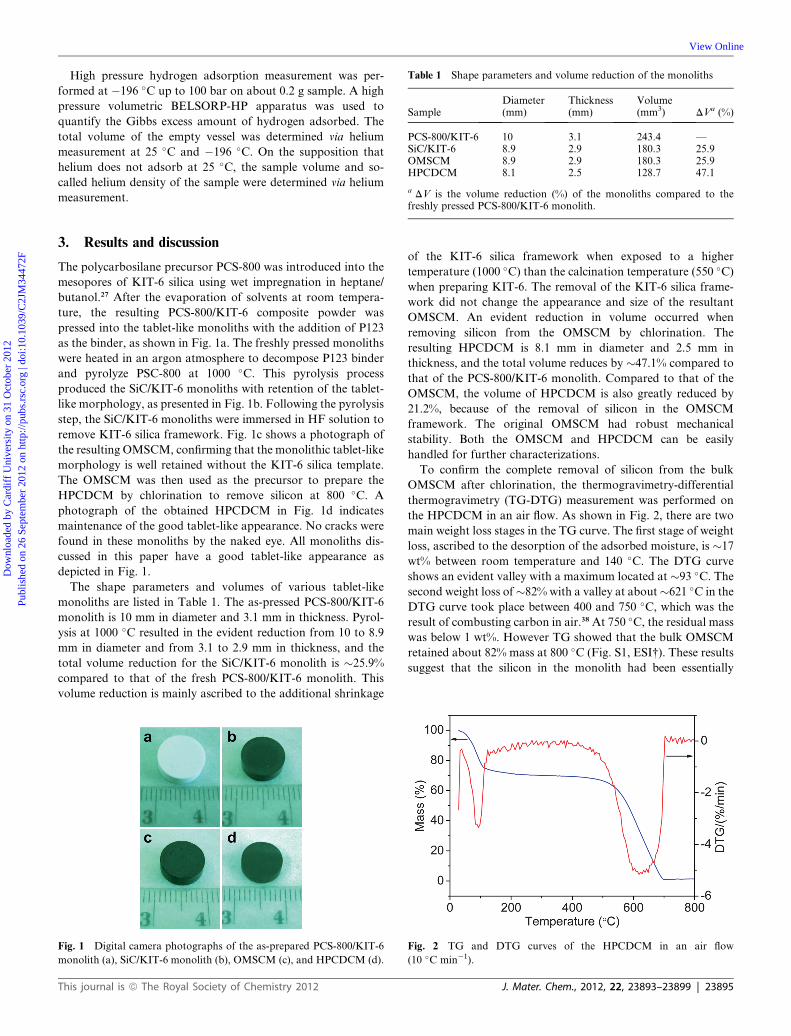
Table 1 Shape parameters and volume reduction of the monoliths
SampleDiameter(mm)
Thickness(mm)
Volume(mm3) DVa (%)
PCS-800/KIT-6 10 3.1 243.4 —SiC/KIT-6 8.9 2.9 180.3 25.9OMSCM 8.9 2.9 180.3 25.9HPCDCM 8.1 2.5 128.7 47.1
a DV is the volume reduction (%) of the monoliths compared to the
Dow
nloa
ded
by C
ardi
ff U
nive
rsity
on
31 O
ctob
er 2
012
Publ
ishe
d on
26
Sept
embe
r 20
12 o
n ht
tp://
pubs
.rsc
.org
| do
i:10.
1039
/C2J
M34
472F
View Online
High pressure hydrogen adsorption measurement was per-
formed at �196 �C up to 100 bar on about 0.2 g sample. A high
pressure volumetric BELSORP-HP apparatus was used to
quantify the Gibbs excess amount of hydrogen adsorbed. The
total volume of the empty vessel was determined via helium
measurement at 25 �C and �196 �C. On the supposition that
helium does not adsorb at 25 �C, the sample volume and so-
called helium density of the sample were determined via helium
measurement.
freshly pressed PCS-800/KIT-6 monolith.3. Results and discussion
The polycarbosilane precursor PCS-800 was introduced into the
mesopores of KIT-6 silica using wet impregnation in heptane/
butanol.27 After the evaporation of solvents at room tempera-
ture, the resulting PCS-800/KIT-6 composite powder was
pressed into the tablet-like monoliths with the addition of P123
as the binder, as shown in Fig. 1a. The freshly pressed monoliths
were heated in an argon atmosphere to decompose P123 binder
and pyrolyze PSC-800 at 1000 �C. This pyrolysis process
produced the SiC/KIT-6 monoliths with retention of the tablet-
like morphology, as presented in Fig. 1b. Following the pyrolysis
step, the SiC/KIT-6 monoliths were immersed in HF solution to
remove KIT-6 silica framework. Fig. 1c shows a photograph of
the resulting OMSCM, confirming that the monolithic tablet-like
morphology is well retained without the KIT-6 silica template.
The OMSCM was then used as the precursor to prepare the
HPCDCM by chlorination to remove silicon at 800 �C. A
photograph of the obtained HPCDCM in Fig. 1d indicates
maintenance of the good tablet-like appearance. No cracks were
found in these monoliths by the naked eye. All monoliths dis-
cussed in this paper have a good tablet-like appearance as
depicted in Fig. 1.
The shape parameters and volumes of various tablet-like
monoliths are listed in Table 1. The as-pressed PCS-800/KIT-6
monolith is 10 mm in diameter and 3.1 mm in thickness. Pyrol-
ysis at 1000 �C resulted in the evident reduction from 10 to 8.9
mm in diameter and from 3.1 to 2.9 mm in thickness, and the
total volume reduction for the SiC/KIT-6 monolith is �25.9%
compared to that of the fresh PCS-800/KIT-6 monolith. This
volume reduction is mainly ascribed to the additional shrinkage
Fig. 1 Digital camera photographs of the as-prepared PCS-800/KIT-6
monolith (a), SiC/KIT-6 monolith (b), OMSCM (c), and HPCDCM (d).
This journal is ª The Royal Society of Chemistry 2012
of the KIT-6 silica framework when exposed to a higher
temperature (1000 �C) than the calcination temperature (550 �C)when preparing KIT-6. The removal of the KIT-6 silica frame-
work did not change the appearance and size of the resultant
OMSCM. An evident reduction in volume occurred when
removing silicon from the OMSCM by chlorination. The
resulting HPCDCM is 8.1 mm in diameter and 2.5 mm in
thickness, and the total volume reduces by �47.1% compared to
that of the PCS-800/KIT-6 monolith. Compared to that of the
OMSCM, the volume of HPCDCM is also greatly reduced by
21.2%, because of the removal of silicon in the OMSCM
framework. The original OMSCM had robust mechanical
stability. Both the OMSCM and HPCDCM can be easily
handled for further characterizations.
To confirm the complete removal of silicon from the bulk
OMSCM after chlorination, the thermogravimetry-differential
thermogravimetry (TG-DTG) measurement was performed on
the HPCDCM in an air flow. As shown in Fig. 2, there are two
main weight loss stages in the TG curve. The first stage of weight
loss, ascribed to the desorption of the adsorbed moisture, is �17
wt% between room temperature and 140 �C. The DTG curve
shows an evident valley with a maximum located at �93 �C. Thesecond weight loss of�82% with a valley at about�621 �C in the
DTG curve took place between 400 and 750 �C, which was the
result of combusting carbon in air.38 At 750 �C, the residual mass
was below 1 wt%. However TG showed that the bulk OMSCM
retained about 82% mass at 800 �C (Fig. S1, ESI†). These results
suggest that the silicon in the monolith had been essentially
Fig. 2 TG and DTG curves of the HPCDCM in an air flow
(10 �C min�1).
J. Mater. Chem., 2012, 22, 23893–23899 | 23895
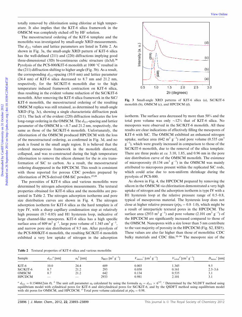
Fig. 3 Small-angle XRD patterns of KIT-6 silica (a), SiC/KIT-6
monolith (b), OMSCM (c), and HPCDCM (d).
Dow
nloa
ded
by C
ardi
ff U
nive
rsity
on
31 O
ctob
er 2
012
Publ
ishe
d on
26
Sept
embe
r 20
12 o
n ht
tp://
pubs
.rsc
.org
| do
i:10.
1039
/C2J
M34
472F
View Online
totally removed by chlorination using chlorine at high temper-
ature. It also implies that the KIT-6 silica framework in the
OMSCM was completely etched off by HF solution.
The mesostructural ordering of the KIT-6 template and the
monoliths was investigated by small-angle XRD measurements.
The d211 values and lattice parameters are listed in Table 2. As
shown in Fig. 3a, the small-angle XRD pattern of KIT-6 silica
has the well-defined (211) and (220) diffractions implying good
three-dimensional (3D) bi-continuous cubic structure (Ia3d).36
Pyrolysis of the PCS-800/KIT-6 monolith at 1000 �C resulted in
the (211) diffraction shifting to higher angle (Fig. 3b). As a result,
the corresponding d211-spacing (10.0 nm) and lattice parameter
(24.4 nm) of KIT-6 silica decreased to 8.7 nm and 21.2 nm,
respectively, for the SiC/KIT-6 monolith due to the high
temperature induced framework contraction on KIT-6 silica,
thus resulting in the evident volume reduction of the SiC/KIT-6
monolith. After removing the KIT-6 silica framework in the SiC/
KIT-6 monolith, the mesostructural ordering of the resulting
OMSCM replica was still retained, as determined by small-angle
XRD (Fig. 3c), showing a single characteristic diffraction peak
(211). The lack of the evident (220) diffraction indicates the low
long-range ordering in the OMSCM. The d211-spacing and lattice
parameter of the OMSCM is �8.7 and 21.2 nm, respectively, the
same as those of the SiC/KIT-6 monolith. Unfortunately, the
chlorination of the OMSCM produced HPCDCM with the loss
of the mesostructural ordering, as confirmed in Fig. 3d, and no
peak is found in the small angle region. It is believed that the
ordered mesoporous framework in the monolith distorted,
collapsed, and was re-constructed during the high temperature
chlorination to remove the silicon element for the in situ trans-
formation of SiC to carbon. As a result, the mesostructural
ordering disappeared in the HPCDCM. This result is consistent
with those reported for porous CDC powders prepared by
chlorination of PCS-derived OM-SiC powders.27,29
The porosities of KIT-6 silica and various monoliths were
determined by nitrogen adsorption measurements. The textural
properties obtained for KIT-6 silica and the monoliths are pre-
sented in Table 2. The nitrogen adsorption isotherms and pore
size distribution curves are shown in Fig. 4. The nitrogen
adsorption isotherm for KIT-6 silica as the hard template is of
type IV, with a sharp capillary condensation step at relatively
high pressure (0.7–0.85) and H1 hysteresis loop, indicative of
large channel-like mesopores. KIT-6 silica has a high specific
surface area of 609 m2 g�1, large pore volume of 1.345 cm3 g�1,
and narrow pore size distribution of 9.5 nm. After pyrolysis of
the PCS-800/KIT-6 monolith, the resulting SiC/KIT-6 monolith
exhibited a very low uptake of nitrogen in the adsorption
Table 2 Textural properties of KIT-6 silica and various monoliths
Sample d211a [nm] a0
b [nm] SBET [m2 g�1]
KIT-6 10.0 24.4 609SiC/KIT-6 8.7 21.2 293OMSCM 8.7 21.2 642HPCDCM — — 2933
a d211 ¼ 0.15406/(2sin q). b The unit cell parameter a0 calculated by using thequilibrium model with cylindrical pores for KIT-6 and slit/cylindrical porewith slit pores for OMSCM, and HPCDCM. d Total pore volume calculated
23896 | J. Mater. Chem., 2012, 22, 23893–23899
isotherm. The surface area decreased by more than 50% and the
total pore volume was only �12% that of KIT-6 silica. No
mesopores were observed in the SiC/KIT-6 monolith. All these
results are clear indications of effectively filling the mesopores of
KIT-6 with SiC. The OMSCM exhibited an enhanced nitrogen
uptake, surface area (642 m2 g�1) and pore volume (0.535 cm3
g�1), which were greatly increased in comparison to those of the
SiC/KIT-6 monolith, due to the removal of the silica template.
There are three peaks at ca. 3.10, 1.85, and 0.96 nm in the pore
size distribution curve of the OMSCM monolith. The existence
of microporosity (0.134 cm3 g�1) in the OMSCM was mainly
attributed to micropores present within the replicated SiC rods,
which could arise due to non-uniform shrinkage during the
pyrolysis of PCS-800.
As shown in Fig. 4, the HPCDCM prepared by removing the
silicon in the OMSCM via chlorination demonstrated a very high
uptake of nitrogen and the adsorption isotherm is type IV with a
H1 hysteresis loop at the relative pressure range of 0.5–0.8,
typical of mesoporous material. The hysteresis loop does not
close at higher relative pressure (p/p0 ¼ 0.8–1.0), which might be
a result of interparticle textural pores in the HPCDCM. The
surface area (2933 m2 g�1) and pore volume (2.101 cm3 g�1) of
the HPCDCM are significantly increased compared to those of
the OMSCM. Nanopores with a size lower than 5 nm contribute
to the vast majority of porosity in the HPCDCM (Fig. S2, ESI†).
These values are also far higher than those of monolithic CDC
bulky materials and CDC film.32–34 The mesopore size of the
Vmicroc [cm3 g�1] Vtotal
d [cm3 g�1] Dmesoc [nm]
0.003 1.345 9.50.050 0.161 2.5–3.60.134 0.535 3.10.981 2.101 3.1
e formula a0 ¼ d211 � 61/2. c Determined by the NLDFT method usings for SiC/KIT-6, and by the QSDFT method using equilibrium modelat p/p0 ¼ 0.98.
This journal is ª The Royal Society of Chemistry 2012

Fig. 4 N2 adsorption–desorption isotherms (a) and pore size distribu-
tion curves (b) of KIT-6, SiC/KIT-6 monolith, OMSCM, and
HPCDCM.
Dow
nloa
ded
by C
ardi
ff U
nive
rsity
on
31 O
ctob
er 2
012
Publ
ishe
d on
26
Sept
embe
r 20
12 o
n ht
tp://
pubs
.rsc
.org
| do
i:10.
1039
/C2J
M34
472F
View Online
HPCDCM is 3.1 nm, exactly the same as that of the OMSCM,
which implied that chlorination could not change the textural
mesopore sizes in the OMSCM. However the total volume of the
HPCDCM decreased by 21.2% compared to that of the
OMSCM. Thus, this reduction is certainly due to the framework
contraction resulting from the in situ transformation of SiC to
carbon. An evident micropore size of �0.9 nm and high micro-
pore volume (0.981 cm3 g�1) are also obtained in the HPCDCM.
The high specific surface area and large pore volume with a large
portion of micropore volume in the HPCDCM are beneficial for
its application in gas storage.
The morphologies of the particles obtained from deliberately
crushing the monoliths were collected by SEM. As presented in
Fig. 5a and b, the particles from the OMSCM show a bulky
structure containing some small particles and no pores could be
found. After the transformation of the OMSCM to HPCDCM
by chlorination, lots of large to small irregular particles with
smooth surfaces generated by crushing the HPCDCM are
observed in Fig. 5c and d. This observation is consistent with the
monolithic morphology from which the particles are derived.39
At the same time, slit macropores of �1 mm in width appeared in
the HPCDCM, possibly due to the evident framework contrac-
tion when chlorinating SiC to carbon.33 These slit macropores
Fig. 5 SEM images of the OMSCM (a and b) and HPCDCM (c and d).
This journal is ª The Royal Society of Chemistry 2012
formed in the HPCDCM are advantageous for the diffusion of
various gases and organic molecules into the mesopores and
micropores. EDX detected the existence of chlorine with �4.3
wt% in the HPCDCM. The existence of chlorine is observed in
various CDC powders prepared by chlorination of carbides with
chlorine at high temperature.
The microstructure of the OMSCM and HPCDCM was
further confirmed by TEM. As shown in Fig. 6a and b, some
circular and stripe-like patterns were observed in the TEM
images of the OMSCM, implying the replication of an ordered
pore structure in the OMSCM after the removal of the silica
template. This result matches well with the small-angle XRD
analysis. Transformation of the OMSCM to HPCDCM by
chlorination resulted in the non-ordered pore structure as shown
in Fig. 6c, although unclear stripes could be observed in some
regions, confirmed by high resolution TEM image (Fig. 6d).
TEM images also indicate that the uniform mesopore size
distribution is well retained, which is necessary for high meso-
porosity in the HPCDCM. This result is consistent with that of
nitrogen adsorption measurement.
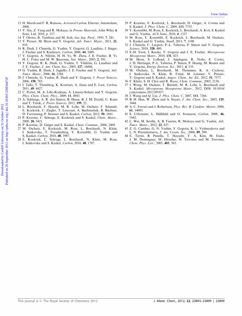
In the Raman spectrum of the HPCDCM shown in Fig. 7, two
broad peaks are observed. One peak at �1300 cm�1 is indicative
of the D band of disordered carbon, and another one at �1600
cm�1 is ascribed to the G-band deriving from graphitic
carbon.28,30,31 The larger ratio of the D-band and G-band
intensities (ID/IG) is consistent with carbon microstructural dis-
ordering and more defects in carbon materials.40 This ID/IGrelative ratio is typical for porous carbons with high degree of
structural disorder, correlating well with the previously reported
amorphous carbons and other CDC materials.30,41–43 This is also
in agreement with the formation of amorphous carbon structure
as observed by TEM measurements.
The hydrogen physisorption isotherm of the HPCDCM up to
1 bar at �196 �C is shown in Fig. 8a. A hydrogen uptake of
�24 mg g�1 is obtained in the HPCDCM at 1 bar. This hydrogen
uptake value is comparable to the previously reported values for
OM-CDC28 and microporous CDC powders.18 The hydrogen
storage capacity of the HPCDCM was also investigated by high
pressure hydrogen adsorption measurement over the pressure
Fig. 6 TEM images of the OMSCM (a and b) and HPCDCM (c and d).
J. Mater. Chem., 2012, 22, 23893–23899 | 23897
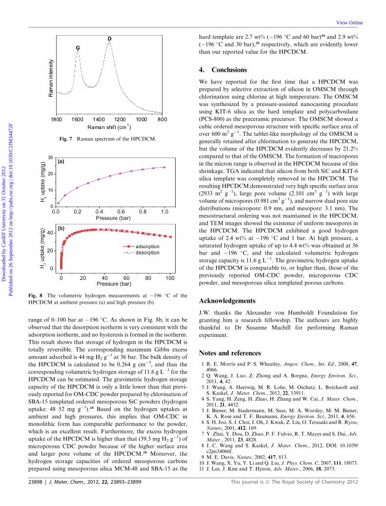
Fig. 7 Raman spectrum of the HPCDCM.
Fig. 8 The volumetric hydrogen measurements at �196 �C of the
HPCDCM at ambient pressure (a) and high pressure (b).
Dow
nloa
ded
by C
ardi
ff U
nive
rsity
on
31 O
ctob
er 2
012
Publ
ishe
d on
26
Sept
embe
r 20
12 o
n ht
tp://
pubs
.rsc
.org
| do
i:10.
1039
/C2J
M34
472F
View Online
range of 0–100 bar at �196 �C. As shown in Fig. 8b, it can be
observed that the desorption isotherm is very consistent with the
adsorption isotherm, and no hysteresis is formed in the isotherm.
This result shows that storage of hydrogen in the HPCDCM is
totally reversible. The corresponding maximum Gibbs excess
amount adsorbed is 44 mg H2 g�1 at 36 bar. The bulk density of
the HPCDCM is calculated to be 0.264 g cm�3, and thus the
corresponding volumetric hydrogen storage of 11.6 g L�1 for the
HPCDCM can be estimated. The gravimetric hydrogen storage
capacity of the HPCDCM is only a little lower than that previ-
ously reported for OM-CDC powder prepared by chlorination of
SBA-15 templated ordered mesoporous SiC powders (hydrogen
uptake: 48–52 mg g�1).28 Based on the hydrogen uptakes at
ambient and high pressures, this implies that OM-CDC in
monolithic form has comparable performance to the powder,
which is an excellent result. Furthermore, the excess hydrogen
uptake of the HPCDCM is higher than that (39.3 mg H2 g�1) of
microporous CDC powder because of the higher surface area
and larger pore volume of the HPCDCM.28 Moreover, the
hydrogen storage capacities of ordered mesoporous carbons
prepared using mesoporous silica MCM-48 and SBA-15 as the
23898 | J. Mater. Chem., 2012, 22, 23893–23899
hard template are 2.7 wt% (�196 �C and 60 bar)44 and 2.9 wt%
(�196 �C and 30 bar),28 respectively, which are evidently lower
than our reported value for the HPCDCM.
4. Conclusions
We have reported for the first time that a HPCDCM was
prepared by selective extraction of silicon in OMSCM through
chlorination using chlorine at high temperature. The OMSCM
was synthesized by a pressure-assisted nanocasting procedure
using KIT-6 silica as the hard template and polycarbosilane
(PCS-800) as the preceramic precursor. The OMSCM showed a
cubic ordered mesoporous structure with specific surface area of
over 600 m2 g�1. The tablet-like morphology of the OMSCM is
generally retained after chlorination to generate the HPCDCM,
but the volume of the HPCDCM evidently decreases by 21.2%
compared to that of the OMSCM. The formation of macropores
in the micron range is observed in the HPCDCM because of this
shrinkage. TGA indicated that silicon from both SiC and KIT-6
silica template was completely removed in the HPCDCM. The
resulting HPCDCM demonstrated very high specific surface area
(2933 m2 g�1), large pore volume (2.101 cm3 g�1) with large
volume of micropores (0.981 cm3 g�1), and narrow dual pore size
distributions (micropore: 0.9 nm, and mesopore: 3.1 nm). The
mesostructural ordering was not maintained in the HPCDCM,
and TEM images showed the existence of uniform mesopores in
the HPCDCM. The HPCDCM exhibited a good hydrogen
uptake of 2.4 wt% at �196 �C and 1 bar. At high pressure, a
saturated hydrogen uptake of up to 4.4 wt% was obtained at 36
bar and �196 �C, and the calculated volumetric hydrogen
storage capacity is 11.6 g L�1. The gravimetric hydrogen uptake
of the HPCDCM is comparable to, or higher than, those of the
previously reported OM-CDC powder, microporous CDC
powder, and mesoporous silica templated porous carbons.
Acknowledgements
J.W. thanks the Alexander von Humboldt Foundation for
granting him a research fellowship. The authours are highly
thankful to Dr Susanne Machill for performing Raman
experiment.
Notes and references
1 R. E. Morris and P. S. Wheatley, Angew. Chem., Int. Ed., 2008, 47,4966.
2 Q. Wang, J. Luo, Z. Zhong and A. Borgna, Energy Environ. Sci.,2011, 4, 42.
3 J. Wang, A. Heerwig, M. R. Lohe, M. Oschatz, L. Borchardt andS. Kaskel, J. Mater. Chem., 2012, 22, 13911.
4 S. Yang, H. Zeng, H. Zhao, H. Zhang and W. Cai, J. Mater. Chem.,2011, 21, 4432.
5 J. Biener, M. Stadermann, M. Suss, M. A. Worsley, M. M. Biener,K. A. Rose and T. F. Baumann, Energy Environ. Sci., 2011, 4, 656.
6 S. H. Joo, S. J. Choi, I. Oh, J. Kwak, Z. Liu, O. Terasaki and R. Ryoo,Nature, 2001, 412, 169.
7 Y. Zhai, Y. Dou, D. Zhao, P. F. Fulvio, R. T. Mayes and S. Dai, Adv.Mater., 2011, 23, 4828.
8 J. C. Wang and S. Kaskel, J. Mater. Chem., 2012, DOI: 10.1039/c2jm34066f.
9 M. E. Davis, Nature, 2002, 417, 813.10 J. Wang, X. Yu, Y. Li and Q. Liu, J. Phys. Chem. C, 2007, 111, 18073.11 J. Lee, J. Kim and T. Hyeon, Adv. Mater., 2006, 18, 2073.
This journal is ª The Royal Society of Chemistry 2012
Dow
nloa
ded
by C
ardi
ff U
nive
rsity
on
31 O
ctob
er 2
012
Publ
ishe
d on
26
Sept
embe
r 20
12 o
n ht
tp://
pubs
.rsc
.org
| do
i:10.
1039
/C2J
M34
472F
View Online
12 H.Marsh and F. R. Reinoso,Activated Carbon, Elsevier, Amsterdam,2006.
13 Y. Xia, Z. Yang and R. Mokaya, in Porous Materials, John Wiley &Sons, Ltd, 2010, p. 217.
14 T. Otowa, R. Tanibata and M. Itoh, Gas Sep. Purif., 1993, 7, 241.15 V. Presser, M. Heon and Y. Gogotsi, Adv. Funct. Mater., 2011, 21,
810.16 R. Dash, J. Chmiola, G. Yushin, Y. Gogotsi, G. Laudisio, J. Singer,
J. Fischer and S. Kucheyev, Carbon, 2006, 44, 2489.17 Y. Gogotsi, A. Nikitin, H. H. Ye, W. Zhou, J. E. Fischer, B. Yi,
H. C. Foley and M. W. Barsoum, Nat. Mater., 2003, 2, 591.18 Y. Gogotsi, R. K. Dash, G. Yushin, T. Yildirim, G. Laudisio and
J. E. Fischer, J. Am. Chem. Soc., 2005, 127, 16006.19 G. Yushin, R. Dash, J. Jagiello, J. E. Fischer and Y. Gogotsi, Adv.
Funct. Mater., 2006, 16, 2288.20 J. Chmiola, G. Yushin, R. Dash and Y. Gogotsi, J. Power Sources,
2006, 158, 765.21 I. Tallo, T. Thomberg, K. Kontturi, A. J€anes and E. Lust, Carbon,
2011, 49, 4427.22 C. Portet, M. A. Lillo-Rodenas, A. Linares-Solano and Y. Gogotsi,
Phys. Chem. Chem. Phys., 2009, 11, 4943.23 A. Schlange, A. R. dos Santos, B. Hasse, B. J. M. Etzold, U. Kunz
and T. Turek, J. Power Sources, 2012, 199, 22.24 L. Borchardt, F. Hasch�e, M. R. Lohe, M. Oschatz, F. Schmidt,
E. Kockrick, C. Ziegler, T. Lescouet, A. Bachmatiuk, B. B€uchner,D. Farrusseng, P. Strasser and S. Kaskel, Carbon, 2012, 50, 1861.
25 P. Krawiec, C. Schrage, E. Kockrick and S. Kaskel, Chem. Mater.,2008, 20, 5421.
26 P. Krawiec, D. Geiger and S. Kaskel, Chem. Commun., 2006, 2469.27 M. Oschatz, E. Kockrick, M. Rose, L. Borchardt, N. Klein,
I. Senkovska, T. Freudenberg, Y. Korenblit, G. Yushin andS. Kaskel, Carbon, 2010, 48, 3987.
28 E. Kockrick, C. Schrage, L. Borchardt, N. Klein, M. Rose,I. Senkovska and S. Kaskel, Carbon, 2010, 48, 1707.
This journal is ª The Royal Society of Chemistry 2012
29 P. Krawiec, E. Kockrick, L. Borchardt, D. Geiger, A. Corma andS. Kaskel, J. Phys. Chem. C, 2009, 113, 7755.
30 Y. Korenblit, M. Rose, E. Kockrick, L. Borchardt, A. Kvit, S. Kaskeland G. Yushin, ACS Nano, 2010, 4, 1337.
31 M. Rose, Y. Korenblit, E. Kockrick, L. Borchardt, M. Oschatz,S. Kaskel and G. Yushin, Small, 2011, 7, 1108.
32 J. Chmiola, C. Largeot, P.-L. Taberna, P. Simon and Y. Gogotsi,Science, 2010, 328, 480.
33 S.-H. Yeon, I. Knoke, Y. Gogotsi and J. E. Fischer, MicroporousMesoporous Mater., 2010, 131, 423.
34 M. Heon, S. Lofland, J. Applegate, R. Nolte, E. Cortes,J. D. Hettinger, P.-L. Taberna, P. Simon, P. Huang, M. Brunet andY. Gogotsi, Energy Environ. Sci., 2011, 4, 135.
35 M. Oschatz, L. Borchardt, M. Thommes, K. A. Cychosz,I. Senkovska, N. Klein, R. Frind, M. Leistner, V. Presser,Y. Gogotsi and S. Kaskel, Angew. Chem., Int. Ed., 2012, 51, 7577.
36 F. Kleitz, S. H. Choi and R. Ryoo, Chem. Commun., 2003, 2136.37 J. Wang, M. Oschatz, T. Biemelt, M. R. Lohe, L. Borchardt and
S. Kaskel, Microporous Mesoporous Mater., 2012, DOI: 10.1016/j.micromeso.2012.09.037.
38 J. Wang and Q. Liu, J. Phys. Chem. C, 2007, 111, 7266.39 B. H. Han, W. Zhou and A. Sayari, J. Am. Chem. Soc., 2003, 125,
3444.40 A. C. Ferrari and J. Robertson, Phys. Rev. B: Condens. Matter, 2000,
61, 14095.41 S. Urbonaite, L. H€alldahl and G. Svensson, Carbon, 2008, 46,
1942.42 L. Wei, M. Sevilla, A. B. Fuertes, R. Mokaya and G. Yushin, Adv.
Funct. Mater., 2012, 22, 827.43 Z. G. Cambaz, G. N. Yushin, Y. Gogotsi, K. L. Vyshnyakova and
L. N. Pereselentseva, J. Am. Ceram. Soc., 2006, 89, 509.44 E. Terr�es, B. Panella, T. Hayashi, Y. A. Kim, M. Endo,
J. M. Dominguez, M. Hirscher, H. Terrones and M. Terrones,Chem. Phys. Lett., 2005, 403, 363.
J. Mater. Chem., 2012, 22, 23893–23899 | 23899
Related Documents


![Fast and efficient synthesis of microporous polymer ......in organic electronics [8]. Among the microporous materials, conjugated microporous polymers (CMPs) [9,10] or porous aro-matic](https://static.cupdf.com/doc/110x72/5ed931156714ca7f47695094/fast-and-efficient-synthesis-of-microporous-polymer-in-organic-electronics.jpg)


