IOP PUBLISHING NANOTECHNOLOGY Nanotechnology 20 (2009) 245607 (6pp) doi:10.1088/0957-4484/20/24/245607 Templated growth of graphenic materials Nolan W Nicholas 1,2,7 , L Matthew Connors 1 , Feng Ding 3 , Boris I Yakobson 4 , Howard K Schmidt 2,5 and Robert H Hauge 2,6 1 Department of Physics, Rice University, 6100 Main, Houston, TX, USA 2 Richard E Smalley Institute for Nanoscale Science and Technology, Rice University, 6100 Main, Houston, TX, USA 3 Institute of Textile and Clothing, Hong Kong Polytechnic University, Kowloon, Hong Kong 4 Department of Mechanical Engineering and Materials Science, Rice University, 6100 Main, Houston, TX, USA 5 Department of Chemical and Biomolecular Engineering, Rice University, 6100 Main, Houston, TX, USA 6 Department of Chemistry, Rice University, 6100 Main, Houston, TX, USA E-mail: [email protected] Received 6 March 2009, in final form 20 April 2009 Published 27 May 2009 Online at stacks.iop.org/Nano/20/245607 Abstract A novel strategy is proposed for the topologically controlled synthesis of extended graphenic sheets by additively reacting carbon into a pre-existing graphene sheet which is on top of a templating substrate. This concept is implemented and demonstrated using chemical vapor deposition (CVD). Novel morphological features observed in this study suggest unusual aspects of the CVD growth process. CVD results demonstrate the basic soundness of the synthesis strategy but highlight the sensitivity of the process to certain types of disruption and the need for alternative forms of embodiment. (Some figures in this article are in colour only in the electronic version) 1. Introduction Since the discovery of carbon nanotubes the remarkable structural, thermal and electronic properties of graphenic lattice materials have become widely appreciated. Planar graphene has recently received a great deal of attention for potential use in a wide range of applications [1–3]. Planar graphene has many remarkable properties including extremely high sheet-strength and the largest diamagnetic response of any bulk room-temperature material [4], and has shown some indications of nanoscopically controllable ferromagnetism [5]. Graphene has attracted particular attention as being useful for high speed nanoelectronics applications and being potentially more easily integrated with existing microelectronics technology [6]. However, graphene suffers from a dearth of scalable sample preparation techniques. Commercially viable applications, particularly electronics, will require reliable large scale production of quality graphene; beyond the production capabilities of current technologies [7]. In graphenic lattice structures topology is 7 Author to whom any correspondence should be addressed. Present address: MATRIC Incorporated, 3200 Kanawha Turnpike, South Charleston, WV 25303, USA. critical to the physical properties of the structure. Electronic properties including metallicity [8], coherence length [9], and charge localization [10] are dictated by the topological characteristics of the graphene lattice. Much of the experimental characterization of graphene has employed small graphene sheets extracted from larger graphite samples. Various methods have been used, such as rubbing planar graphite [11], lithographic etching with micromanipulation [12], and chemically solubilizing ‘platelets’ from graphite [13, 14]. This approach is also inherently size limited by the currently available graphite materials (generally 10 μ or smaller) [15] and provides no feasible route to precise topological control. The most successful technique to date for producing graphene directly, and which has been widely used to study its promising electronic properties, has been the heteroepitaxial synthesis of graphene materials onto a 6H-SiC substrate by selective evaporation of silicon from the substrate so that the remaining excess carbon assembles into a graphene coating on the surface [16]. While this approach has demonstrated the potential for high quality electronics devices built from graphene, the inherent materials and UHV process limitations of this technique have led to the exploration of other techniques 0957-4484/09/245607+06$30.00 © 2009 IOP Publishing Ltd Printed in the UK 1

Welcome message from author
This document is posted to help you gain knowledge. Please leave a comment to let me know what you think about it! Share it to your friends and learn new things together.
Transcript
IOP PUBLISHING NANOTECHNOLOGY
Nanotechnology 20 (2009) 245607 (6pp) doi:10.1088/0957-4484/20/24/245607
Templated growth of graphenic materialsNolan W Nicholas1,2,7, L Matthew Connors1, Feng Ding3,Boris I Yakobson4, Howard K Schmidt2,5 and Robert H Hauge2,6
1 Department of Physics, Rice University, 6100 Main, Houston, TX, USA2 Richard E Smalley Institute for Nanoscale Science and Technology, Rice University, 6100Main, Houston, TX, USA3 Institute of Textile and Clothing, Hong Kong Polytechnic University, Kowloon, Hong Kong4 Department of Mechanical Engineering and Materials Science, Rice University, 6100 Main,Houston, TX, USA5 Department of Chemical and Biomolecular Engineering, Rice University, 6100 Main,Houston, TX, USA6 Department of Chemistry, Rice University, 6100 Main, Houston, TX, USA
E-mail: [email protected]
Received 6 March 2009, in final form 20 April 2009Published 27 May 2009Online at stacks.iop.org/Nano/20/245607
AbstractA novel strategy is proposed for the topologically controlled synthesis of extended graphenicsheets by additively reacting carbon into a pre-existing graphene sheet which is on top of atemplating substrate. This concept is implemented and demonstrated using chemical vapordeposition (CVD). Novel morphological features observed in this study suggest unusual aspectsof the CVD growth process. CVD results demonstrate the basic soundness of the synthesisstrategy but highlight the sensitivity of the process to certain types of disruption and the needfor alternative forms of embodiment.
(Some figures in this article are in colour only in the electronic version)
1. Introduction
Since the discovery of carbon nanotubes the remarkablestructural, thermal and electronic properties of grapheniclattice materials have become widely appreciated. Planargraphene has recently received a great deal of attentionfor potential use in a wide range of applications [1–3].Planar graphene has many remarkable properties includingextremely high sheet-strength and the largest diamagneticresponse of any bulk room-temperature material [4], andhas shown some indications of nanoscopically controllableferromagnetism [5]. Graphene has attracted particularattention as being useful for high speed nanoelectronicsapplications and being potentially more easily integratedwith existing microelectronics technology [6]. However,graphene suffers from a dearth of scalable sample preparationtechniques. Commercially viable applications, particularlyelectronics, will require reliable large scale production ofquality graphene; beyond the production capabilities of currenttechnologies [7]. In graphenic lattice structures topology is
7 Author to whom any correspondence should be addressed. Present address:MATRIC Incorporated, 3200 Kanawha Turnpike, South Charleston, WV25303, USA.
critical to the physical properties of the structure. Electronicproperties including metallicity [8], coherence length [9],and charge localization [10] are dictated by the topologicalcharacteristics of the graphene lattice.
Much of the experimental characterization of graphenehas employed small graphene sheets extracted from largergraphite samples. Various methods have been used,such as rubbing planar graphite [11], lithographic etchingwith micromanipulation [12], and chemically solubilizing‘platelets’ from graphite [13, 14]. This approach is alsoinherently size limited by the currently available graphitematerials (generally 10 μ or smaller) [15] and provides nofeasible route to precise topological control.
The most successful technique to date for producinggraphene directly, and which has been widely used to study itspromising electronic properties, has been the heteroepitaxialsynthesis of graphene materials onto a 6H-SiC substrate byselective evaporation of silicon from the substrate so that theremaining excess carbon assembles into a graphene coatingon the surface [16]. While this approach has demonstratedthe potential for high quality electronics devices built fromgraphene, the inherent materials and UHV process limitationsof this technique have led to the exploration of other techniques
0957-4484/09/245607+06$30.00 © 2009 IOP Publishing Ltd Printed in the UK1
Nanotechnology 20 (2009) 245607 N W Nicholas et al
for graphene synthesis for technological applications. Variousother methods producing graphenic materials have beenexplored [17–22]; however, none of these methods is scalableto topologically controlled synthesis of graphenic materialson substrates suitable for technological applications. Thisprovides significant motivation to better understand the basicphysical mechanisms controling the growth of graphenicmaterials.
We propose and report here a new approach forsynthesizing graphene structures. This method has beenobserved to grow sheets of graphene by additively reactingcarbon molecules into a pre-existing graphene sheet resting onan inert templating substrate. It is shown that by reducing thedegrees of freedom available to the system, graphenic materialswith controlled topologies can be grown through simple CVDprocesses. Furthermore, this demonstration suggests that non-CVD methods may be utilized to synthesize graphenes withcontrolled topologies on various substrates.
2. Templated growth mechanism
Several factors contribute to the observed difficulty insynthesizing pristine graphene. Growing a sheet of grapheneis essentially a process of epitaxy at a one-dimensional sheetedge to extend a two-dimensional planar lattice (in contrastto traditional epitaxy which occurs at a plane edge to form athree-dimensional lattice). This places particularly stringentrequirements on the growth process. In order to create a single-crystal graphene lattice, nucleation of any other configurationmust be suppressed; only additive growth of carbon atoms intothe pre-existing graphene lattice will create arbitrarily largepristine graphene sheets.
Nucleation of new graphene lattices will tend to leadeither to stacking of graphene sheets into bulk graphites orto co-planar graphene sheets and, ultimately, a polycrystallinematerial of orientationally mismatched graphene lattices.Such structures are commonly observed in CVD depositedgraphites [23]. Incorporation of carbon feedstocks intographitic lattice edges has been previously observed but hasnot been utilized to synthesize and extend graphenic lattices ofcontrolled geometry [24].
Bond configuration defects can also disrupt the formationof pristine graphene lattices. Both sp1 and sp3 carbon bondstructures can be formed and compete with the formation of aperfect hexagonal lattice of sp2 bonded carbon. Topologicaldefects can also occur in completely sp2 bonded carbonlattices by the formation of pentagons or heptagons insteadof hexagons. These factors dictate that defect structures atthe graphene edge will dominate if the growth is rate limitedby the reactivity of the graphene sheet edge. Once a defecthas been enclosed in the lattice the activation energy and timerequired to anneal out the defect increases, so that enclosurearound such a defect effectively seals it into the lattice.
These difficulties can be addressed by: (1) providing atemplate surface for growth; (2) delivering feedstock gas at arate lower than the defect annealing rate; (3) suppressing thetendency of the system to nucleate extraneous carbonaceousmaterials—step-edge chemistry must dominate. While points
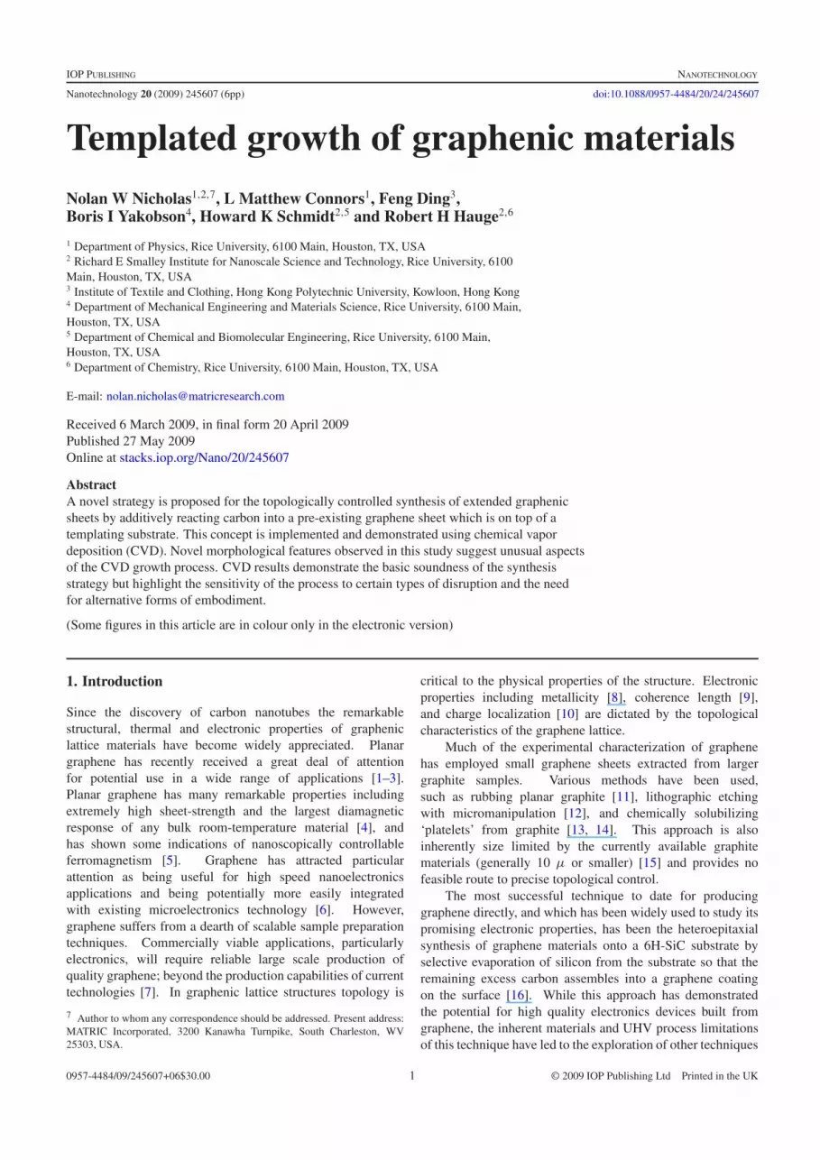
Figure 1. (A) The effects of templating are illustrated. A graphenelattice (shown in darker gray) rests on top of two lower graphenelayers (shown in lighter gray) which act as a van der Waals templateto the top layer. Solid features indicate extra atoms in the lattice as anlinear edge dislocation and an added dimer. The edge dislocation hasan associated energy cost of 16 eV and the added dimer has anenergy cost of ∼4–5 eV with respect to an unstrained lattice. For theedge dislocation shown ∼13% of this is due to template interaction,for the added dimer only ∼4% of this energy is due to templateinteraction. These energies are calculated using the potential shownin (B). (B) The interaction of carbon atoms in this system wascalculated using the Brenner [29] potential for intra-layer carbonatoms and with the Lennard-Jones (LJ) potential (parameterσ = 0.337 nm, ε = 0.042 038 eV) for interlayer interactions.
2 and 3 are typical of an epitaxial CVD process, the first pointis unique to the two-dimensional lattice epitaxy required fortopologically controlled synthesis of graphenic materials:
(1) Templating surface: a non-reactive template such as acontinuous sheet of graphene underlying the growinggraphene layer applies a Lennard-Jones-like van derWaals potential [25] to the growing edge. This potentialincreases the energetic cost of all deviations from apristine graphene sheet and geometrically reduces thespace of favorable states available for growing materialsto be included in the lattice. The non-reactive characterof the substrate ensures that it does not stabilize non-sp2bonds in the growing graphene. This idea is illustratedin figure 1. It is noteworthy that similar processes havepreviously been observed for various graphenic materialsbut have not been recognized as useful mechanisms intheir own right [19, 26–28].
2
Nanotechnology 20 (2009) 245607 N W Nicholas et al
(2) Well-annealed carbon addition: carbon can be added tothe graphene edge in a variety of different configurations.Furthermore, configurations not corresponding to thegrowth of pristine graphene are more kinetically reactivethan those which do. Therefore if the carbon feedstockis supplied at a higher rate than defects can be annealedout of the edge [30] then growth will be dominated byreaction at defect sites forming a highly defective carbonlattice. This is accomplished through a combination ofhigh graphene temperatures to speed annealing and lowfeedstock partial pressures. Etchants can also be selectedto attack defects preferentially.
(3) Nucleation suppression: nucleation is suppressed bymaintaining the system at a low sooting potential bykeeping the feedstock at low partial pressures and lowtemperatures while maintaining the growing edge at hightemperatures.
Together, these three elements provide a novel methodsuitable for the controlled growth of graphenic materials.
3. Experimental details
All experiments were performed on cleaved Highly orderedpyrolytic graphite (HOPG; Structure Probe Incorporated, SPI-1 grade) in a 1 inch diameter quartz tube furnace (LindbergBlue) at temperatures from 800 to 1100 ◦C.
Hydrocarbon, alcohol and ketone species were providedas carbon feedstocks. Ethylene (Matheson Tri-Gas, PolymerGrade) was introduced through a standard gas flow controller.Alcohol (ethanol, 2-propanol and allyl alcohol) and ketone(acetone) species were drawn off as vapors from degassedliquid sources at low pressure; flow was regulated througha needle valve to maintain constant pressure (<150 mTorr)inside the furnace which was backed by a mechanical vacuumpump (Welch 1397, 500 l min1). Water was added to sometests with alcohol feedstocks to provide an etchant species inthe growth environment; this was added by mixing water tothe standard azeotropic composition for the alcohol followedby degassing the solution and evaporating off over half of themixture at low pressure to achieve a steady state composition.
Graphene growth has been obtained using several classesof carbon feedstocks: hydrocarbon, alcohol and ketone specieshave all produced growth of graphene sheets. The best resultshave been obtained with ethanol. It is thought that the OHgroup carried by the ethanol reduces the sooting potential of thesystem and provides an etchant which reduces the tendency togrow defective material. Argon (Matheson Tri-Gas, UltraHighPurity) was used as the diluent carrier gas for the feedstock.Trials were conducted in which nanopure water was includedas an etchant in the system.
Grown materials were characterized by atomic forcemicroscopy (AFM; Veeco Nanoscope IIIa). Figures depictedhere are from AFM surface scans which measure the height ofthe grown material. All AFM characterization was performedin tapping mode using a silicon cantilever probe.
4. Results and discussion
This method has been observed to grow graphenic materialswhich are topologically templated over a graphite basal plane.Characterization of these results as growth features wasconfirmed by a series of before and after AFM observations ofthe same region which demonstrated that the features observedwere the result of material addition rather than etching or othermechanisms. Both the extension of pre-existing graphenicsheets and the nucleation of new sheets has been observed, butthe rate of nucleation has been maintained at very low levels(0.0015–0.0035 nucleations per square micrometer per minuteon the free basal plane; edge driven nucleation can exhibitrates several orders of magnitude greater). A strong tendencytoward higher quality graphene growth and fewer side productswas observed with increasing temperature. Ethanol basedfeedstocks gave the best growth results; ethylene, 2-propanoland acetone also produced reasonable templated growth. Allylalcohol based feedstocks (with and without water) producedonly non-graphenic carbon features.
Ethanol feedstock partial pressures from 5 to 20 mTorr(0.1–0.3 mTorr background) have shown graphene sheetgrowth with low rates of nucleation. The process showsextreme sensitivity to low levels of contamination. Suchcontamination can be overwhelmed by using higher feedstockpartial pressures with premixed etchant species (such aswater) to dominate the reaction system; oxygen in particularis believed to be deleterious, possibly in relation to itsability to attack at non-step-edge sites in graphene andparticipate in non-hexagonal structures and out-of-planebonding geometries [31]. Feedstocks containing water showgraphenic growth at higher pressures but also show highernucleation and may be prone to higher defect rates.
Graphene grown by this method shows several morpho-logical features not observed in as-cleaved HOPG which helpto elucidate the growth dynamics. In order to efficiently char-acterize the observations made, we introduce the followingterminology: growth which extends a pre-existing step-edgeoutward without other superstructural feature is termed ‘sheet’growth. Some growth conditions are observed to grow materialwhich has a topographical roughness under AFM significantlygreater than for as-cleaved HOPG, giving it a ‘crinkled’ ap-pearance. In all cases of sheet growth, the number of grapheniclayers in a sheet (as measured by AFM height profiles) wasfound to be the same as the number of layers in the step-edgefrom which it grew. Growth extending from a pre-existingedge will occasionally develop a spiral structure correspond-ing to growth around a screw dislocation. Growth of circulargraphene structures which are not derived from a pre-existinggraphene edge and which are single graphene layers in height(or occasionally double) has been observed; these are termedplatelets. Structures resembling a circle with a wedge missinghave been observed to form at growing edges, these are termed‘Pacman’ morphologies. Non-graphenic carbon has also beenobserved to grow under certain conditions and is termed ‘nodu-lar carbon’ due to the morphological shapes it takes.
Sheet growth is universally observed to grow roundedfeatures from sharp corners in the pre-existing step-edge and
3
Nanotechnology 20 (2009) 245607 N W Nicholas et al
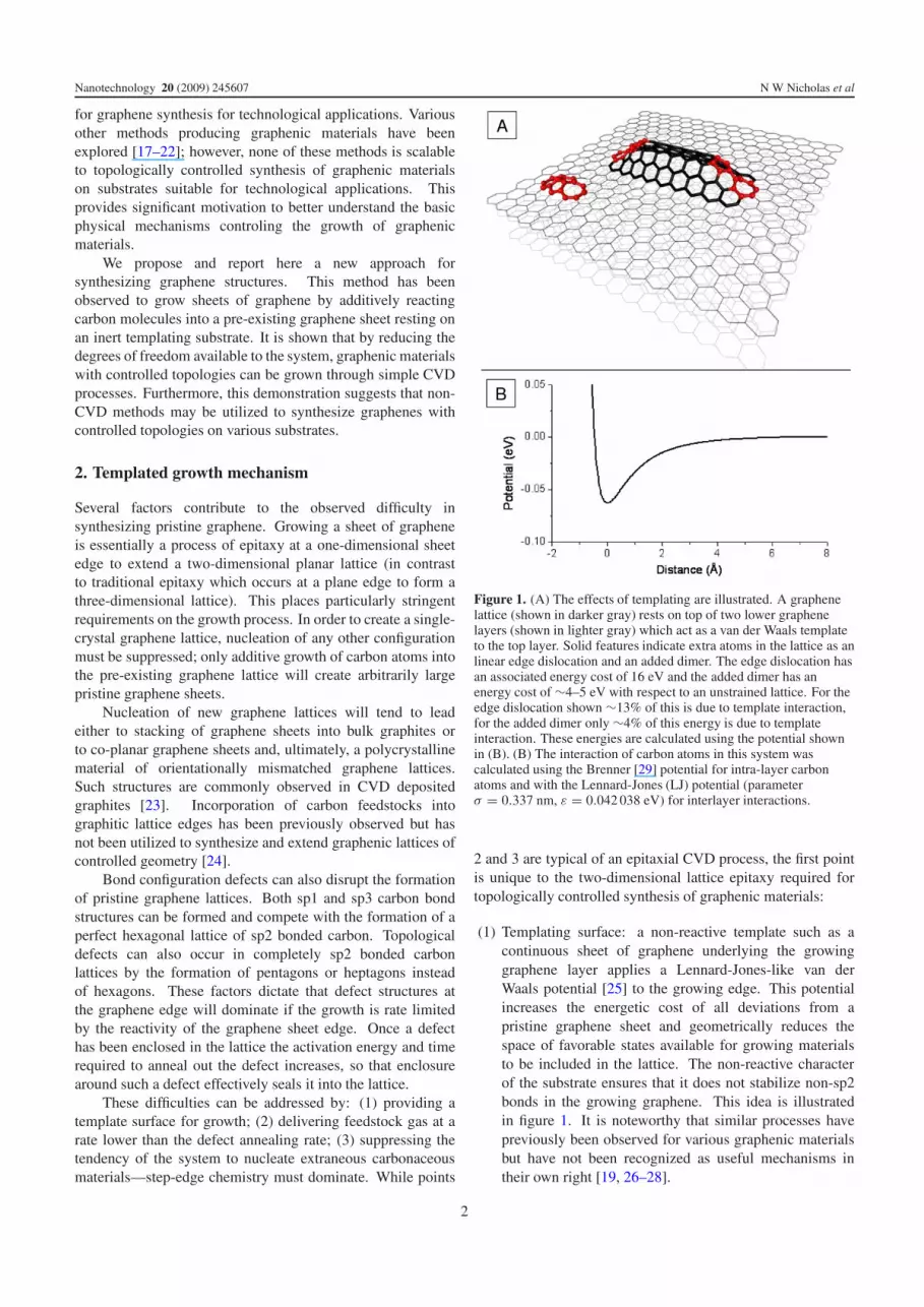
Figure 2. (A) Crinkled growth is seen extending from a pre-existing step-edge; the locations of the pre-existing step-edges are demarcated bydashed black lines and the direction of sheet growth is indicated by solid black arrows. Crinkled (imperfect) growth is clearly observed as achange in roughness of the surface relative to the native HOPG surface; the edges of this roughness clearly delineate sheet growths from theoriginal HOPG material and allow measurement of linear growth. Platelet growth is also observed, notably all platelets formed at step-edge orother defect sites. This particularly highlights the competing processes of nucleation (which forms platelets), and sheet growth at step-edgesites. (B) Both crinkled and pristine growth are seen extending from the same step-edges as portions of the same sheet growth. The presenceof both crinkled growth and pristine growth as different parts of the growth of the same sheet clearly demonstrates pristine growth buthighlights the sensitivity of the conditions under which it is occurs.
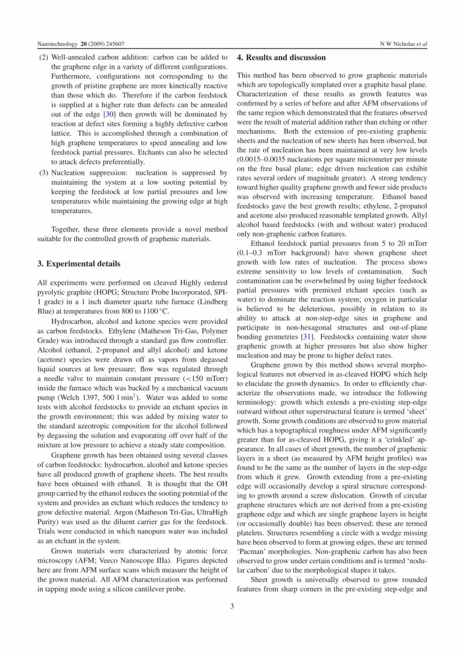
Figure 3. A spiral is observed in conjunction with pristine sheetgrowth.
platelets universally form circular or nearly circular graphenesheets. These observations indicate that despite recent reportsof the difference in crystallographic stability of various latticeedges [32, 33] this growth process shows very little selectivityof crystallographic axis under the growth conditions tested.Only in the growth of spirals have angular growth featuresbeen occasionally observed which may be indicative of somecrystallographic selectivity.
Crinkled sheet growth is believed to be the result ofthe growth of graphene with a high density of structuraldefects, such as added dimers and edge dislocations, presentin the sheet. Sheet defects of these types are illustrated infigure 1. These topological defects create strained regions inthe lattice causing it to protrude upward (as it cannot protrude
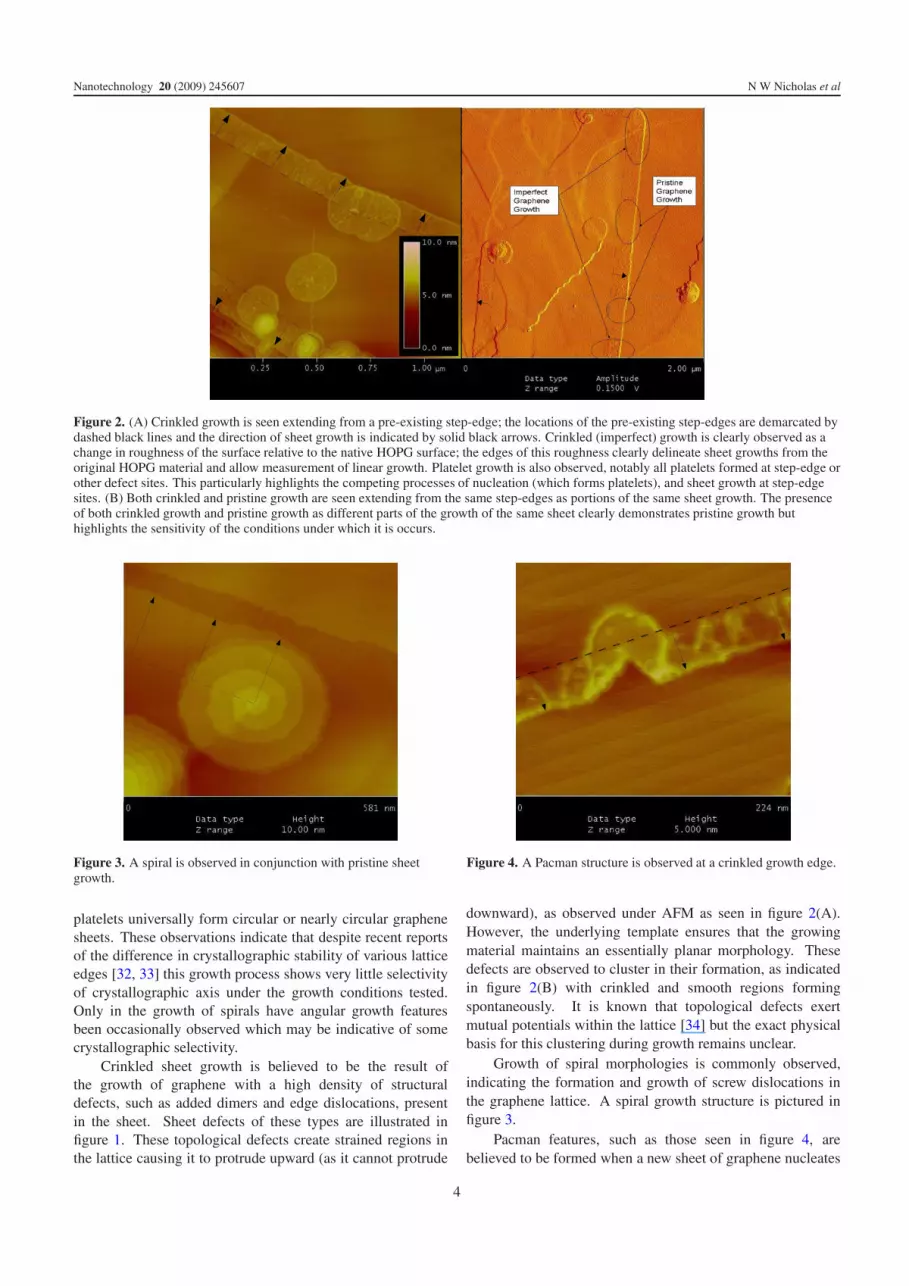
Figure 4. A Pacman structure is observed at a crinkled growth edge.
downward), as observed under AFM as seen in figure 2(A).However, the underlying template ensures that the growingmaterial maintains an essentially planar morphology. Thesedefects are observed to cluster in their formation, as indicatedin figure 2(B) with crinkled and smooth regions formingspontaneously. It is known that topological defects exertmutual potentials within the lattice [34] but the exact physicalbasis for this clustering during growth remains unclear.
Growth of spiral morphologies is commonly observed,indicating the formation and growth of screw dislocations inthe graphene lattice. A spiral growth structure is pictured infigure 3.
Pacman features, such as those seen in figure 4, arebelieved to be formed when a new sheet of graphene nucleates
4
Nanotechnology 20 (2009) 245607 N W Nicholas et al
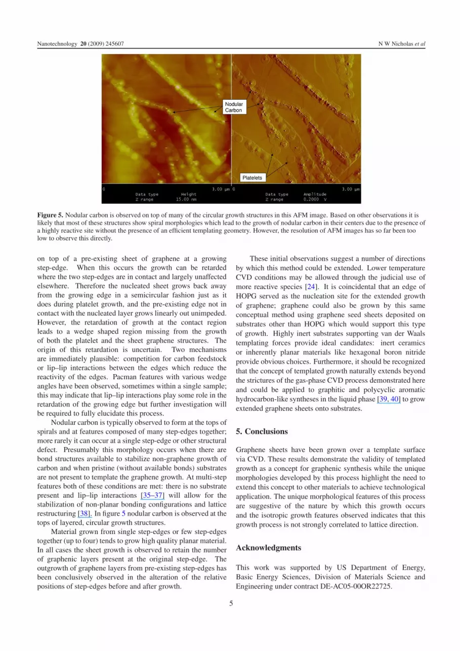
Figure 5. Nodular carbon is observed on top of many of the circular growth structures in this AFM image. Based on other observations it islikely that most of these structures show spiral morphologies which lead to the growth of nodular carbon in their centers due to the presence ofa highly reactive site without the presence of an efficient templating geometry. However, the resolution of AFM images has so far been toolow to observe this directly.
on top of a pre-existing sheet of graphene at a growingstep-edge. When this occurs the growth can be retardedwhere the two step-edges are in contact and largely unaffectedelsewhere. Therefore the nucleated sheet grows back awayfrom the growing edge in a semicircular fashion just as itdoes during platelet growth, and the pre-existing edge not incontact with the nucleated layer grows linearly out unimpeded.However, the retardation of growth at the contact regionleads to a wedge shaped region missing from the growthof both the platelet and the sheet graphene structures. Theorigin of this retardation is uncertain. Two mechanismsare immediately plausible: competition for carbon feedstockor lip–lip interactions between the edges which reduce thereactivity of the edges. Pacman features with various wedgeangles have been observed, sometimes within a single sample;this may indicate that lip–lip interactions play some role in theretardation of the growing edge but further investigation willbe required to fully elucidate this process.
Nodular carbon is typically observed to form at the tops ofspirals and at features composed of many step-edges together;more rarely it can occur at a single step-edge or other structuraldefect. Presumably this morphology occurs when there arebond structures available to stabilize non-graphene growth ofcarbon and when pristine (without available bonds) substratesare not present to template the graphene growth. At multi-stepfeatures both of these conditions are met: there is no substratepresent and lip–lip interactions [35–37] will allow for thestabilization of non-planar bonding configurations and latticerestructuring [38]. In figure 5 nodular carbon is observed at thetops of layered, circular growth structures.
Material grown from single step-edges or few step-edgestogether (up to four) tends to grow high quality planar material.In all cases the sheet growth is observed to retain the numberof graphenic layers present at the original step-edge. Theoutgrowth of graphene layers from pre-existing step-edges hasbeen conclusively observed in the alteration of the relativepositions of step-edges before and after growth.
These initial observations suggest a number of directionsby which this method could be extended. Lower temperatureCVD conditions may be allowed through the judicial use ofmore reactive species [24]. It is coincidental that an edge ofHOPG served as the nucleation site for the extended growthof graphene; graphene could also be grown by this sameconceptual method using graphene seed sheets deposited onsubstrates other than HOPG which would support this typeof growth. Highly inert substrates supporting van der Waalstemplating forces provide ideal candidates: inert ceramicsor inherently planar materials like hexagonal boron nitrideprovide obvious choices. Furthermore, it should be recognizedthat the concept of templated growth naturally extends beyondthe strictures of the gas-phase CVD process demonstrated hereand could be applied to graphitic and polycyclic aromatichydrocarbon-like syntheses in the liquid phase [39, 40] to growextended graphene sheets onto substrates.
5. Conclusions
Graphene sheets have been grown over a template surfacevia CVD. These results demonstrate the validity of templatedgrowth as a concept for graphenic synthesis while the uniquemorphologies developed by this process highlight the need toextend this concept to other materials to achieve technologicalapplication. The unique morphological features of this processare suggestive of the nature by which this growth occursand the isotropic growth features observed indicates that thisgrowth process is not strongly correlated to lattice direction.
Acknowledgments
This work was supported by US Department of Energy,Basic Energy Sciences, Division of Materials Science andEngineering under contract DE-AC05-00OR22725.
5

Nanotechnology 20 (2009) 245607 N W Nicholas et al
References
[1] Novoselov K S et al 2004 Electric field effect in atomically thincarbon films Science 306 666–9
[2] Kane C 2005 Erasing electron mass Nature 438 168–70[3] Berger C et al 2006 Electronic confinement and coherence in
patterned epitaxial graphene Science 312 1191–6[4] Flandrois S 2001 Magnetic properties of graphite and graphitic
carbons Graphite and Precursors (World of Carbon) edP Delhaes (Amsterdam: Gordon and Breach) pp 71–85
[5] Esquinazi P, Setzer A and Hoehne R 2002 Ferromagnetism inoriented graphite samples Phys. Rev. B 66 024429
[6] Ball P 2004 Material witness: flat out C60 Nat. Mater. 5 43[7] Van Noorden R 2006 Moving towards a graphene world Nature
442 228–9[8] Mintmire J W, Dunlap B I and White C T 1992 Are fullerene
tubules metallic? Phys. Rev. Lett. 68 631–4[9] Morpurgo A and Guinea F 2006 Intervalley scattering,
long-range disorder, and effective time-reversal symmetrybreaking in graphene Phys. Rev. Lett. 97 196804
[10] Azevedo S, Furtado C and Moraes F 1998 Charge localizationaround disclinations in monolayer graphite Phys. StatusSolidi b 207 387–92
[11] Novoselov K S et al 2005 Two-dimensional atomic crystalsProc. Natl Acad. Sci. 102 10451–3
[12] Lu X, Huang H, Nemchuk N and Ruoff R 1999 Patterning ofhighly oriented pyrolytic graphite by oxygen plasma etchingAppl. Phys. Lett. 75 193–5
[13] Si Y and Samulski E T 2008 Synthesis of water solublegraphene Nano Lett. 8 1679–82
[14] Stankovich S, Piner R D, Chen X, Wu N, Nguyen S T andRuoff R 2006 Stable aqueous dispersions of graphiticnanoplatelets via the reductionof exfoliated graphite oxide inthe presence of poly(sodium4-styrenesulfonate) J. Mater.Chem. 1 155–8
[15] Moore A W 1967 Highly Oriented Pyrolitic Graphite(Chemistry and Physics of Carbon) ed P L Walker(New York: Dekker) pp 69–176
[16] Berger C et al 2004 Ultrathin epitaxial graphite: 2D electrongas properties and a route toward graphene-basednanoelectronics J. Phys. Chem. B 108 19912–6
[17] Wang J J et al 2004 Free-standing subnanometer graphitesheets Appl. Phys. Lett. 85 1265–7
[18] Kastler M, Schmidt J, Pisula W, Sebastiani D andMuellen K 2006 From armchair to zigzag peripheries innanographenes J. Am. Chem. Soc. 128 9526–34
[19] Wellmann R, Bottcher A, Kappes M, Kohl U andNiehus H 2003 Growth of graphene layers on HOPG viaexposure to methyl radicals Surf. Sci. 542 81–93
[20] Nagashima A, Tejima N, Kawai T and Oshima C 1995Electronic dispersion relations of monolayer hexagonalboron nitride formed on the Ni(111 surface) Phys. Rev. B51 4606
[21] Nakhmanson M S and Smirnov V P 1972 Sov. Phys.—SolidState 13 2763 in Russian
[22] Malesevic A et al 2008 Synthesis of few-layer graphene viamicrowave plasma-enhanced chemical vapour depositionNanotechnology 19 305604
[23] Obraztov A, Obraztova E A, Tyurnina A V andZolotukhin A A 2007 Chemical vapor deposition of thingraphite films of nanometer thickness Carbon 45 2017–21
[24] Lee S Y, Kwak J H, Han G Y, Lee T J and Yoon K J 2008Characterization of active sites for methane decompositionon carbon black through acetylene chemisorption Carbon46 342–8
[25] Girifalco L A, Hodak M and Lee R S 2000 Carbon nanotubes,ropes, buckyballs and a universal graphitic potential Phys.Rev. B 62 13104–10
[26] Charlier J C and Iijima S 2001 Growth Mechanisms of CarbonNanotubes Carbon Nanotubes (Topics Applied Physics) edM Dresselhaus, G Dresselhaus and P Avouris (Berlin:Springer) pp 55–81
[27] Iijima S, Ajayan P and Ichihashi T 1992 Growth model forcarbon nanotubes Phys. Rev. Lett. 69 3100–3
[28] Louchev O and Sato Y 1999 Nanotube self-organization:formation by step-flow growth Appl. Phys. Lett. 74 194–6
[29] Brenner D W 1990 Empirical potential for hydrocarbons foruse in simulating the chemical vapor deposition of diamondfilms Phys. Rev. B 42 9458–71
[30] Frenklach M and Ping J 2004 On the role of surface migrationin the growth and structure of graphene layers Carbon42 1209–12
[31] Ajayan P and Yakobson B 2006 Material science: oxygenbreaks into carbon world Nature 441 818–9
[32] Girit C et al 2009 Graphene at the edge: stability and dynamicsScience 323 1705–8
[33] Jia X, Hofmann M, Meunier V, Sumpter B G,Campos-Delgado J and Romo-Herrera J M 2009 Controlledformation of sharp zigzag and armchair edges in graphiticnanoribbons Science 323 1701–5
[34] Zhang X, Jiao K, Sharma P and Yakobson B I 2006 Anatomistic andnon-classical continuum field theoreticperspective of elasticinteractions between defects (forcedipoles) of various symmetries andapplication to grapheneJ. Mech. Phys. Solids 54 2304–29
[35] Guo T, Nikolaev P, Rinzler A G, Tomanek D, Colbert D T andSmalley R E 1995 Self-assembly of tubular fullerenesJ. Phys. Chem. 99 10694–7
[36] Nardelli M B, Roland C and Bernholc J 1998 Theoreticalbounds for multiwalled carbon nanotube growth Chem.Phys. Lett. 296 471–6
[37] Choi Y, Park K A, Kim C and Lee Y H 2004 Oxygengas-induced lip–lip interactions on a double-walled carbonnanotube edge J. Am. Chem. Soc. 126 9433–8
[38] Rotkin S and Gogotsi Y 2002 Analysis of non-planar graphiticstructures: from arched edge planes of graphite crystals tonanotubes Mater. Res. Innov. 5 191–200
[39] Xiao Y et al 2006 Flower-like carbon materials prepared via asimple solvothermal route Carbon 44 1589–91
[40] Weiss K, Beernink G, Dotz F, Birkner A, Mullen K andWoll C H 1999 Template-mediated synthesis of polycyclicaromatic hydrocarbons: cyclodehydrogenation andplanarization of a hexaphenylbenzene derivative at a coppersurface Angew. Chem. Int. Edn 38 3748–52
6
Related Documents


![eBook Production: A Templated Workflow [2013]](https://static.cupdf.com/doc/110x72/5596c5c01a28ab51408b46a5/ebook-production-a-templated-workflow-2013.jpg)


