Chapter No. 06 Synchronous Generator Dr. Intesar Ahmed, Engr. Kashif Imran, Engr. Muhammad Shuja Khan Department of Electrical Engineering COMSATS Institute of Information Technology Lahore

Welcome message from author
This document is posted to help you gain knowledge. Please leave a comment to let me know what you think about it! Share it to your friends and learn new things together.
Transcript
Chapter No. 06
Synchronous Generator
Dr. Intesar Ahmed, Engr. Kashif Imran,
Engr. Muhammad Shuja Khan
Department of Electrical Engineering
COMSATS Institute of Information Technology
Lahore
Introduction
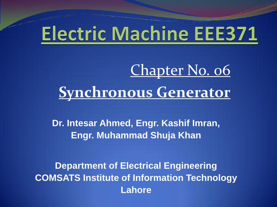
In power stations, 3-Φ AC generator is used to produced 3-Φ voltage with
low magnitude. This low magnitude of voltage is increased by using power
transformer.
The machine which generates 3-Φ electric power from the mechanical power
Is called an alternator or synchronous generator. The shaft of the generator is
coupled with mechanical turbine. The turbine may be gas, steam or water.
A synchronous machine with no-load is called asynchronous condenser or
dynamic capacitor (used to correct the power factor).
ConstructionStator
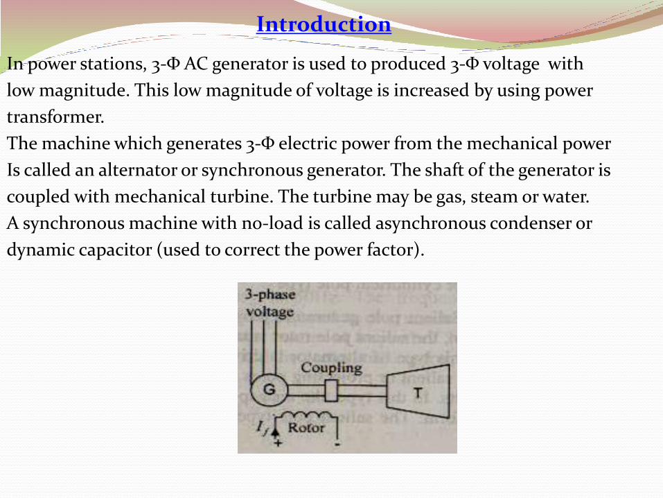
The stator is the stationary part and is made of thin laminations of highly
permeable steel to reduce losses.
The stator has ample number of slots in its inner periphery for stator winding.
The conductors are placed in these slots in a suitable way. The ends of the
conductors are connected either in Υ or Δ to form the balanced 3-Φ winding.
Rotor
It is the inner part of the alternator. It contains the field windings which are
energized by direct current from the separate dc source.
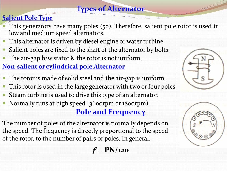
Types of AlternatorSalient Pole Type
This generators have many poles (50). Therefore, salient pole rotor is used inlow and medium speed alternators.
This alternator is driven by diesel engine or water turbine.
Salient poles are fixed to the shaft of the alternator by bolts.
The air-gap b/w stator & the rotor is not uniform.
Non-salient or cylindrical pole Alternator
The rotor is made of solid steel and the air-gap is uniform.
This rotor is used in the large generator with two or four poles.
Steam turbine is used to drive this type of an alternator.
Normally runs at high speed (3600rpm or 1800rpm).
Pole and Frequency
The number of poles of the alternator is normally depends on the speed. The frequency is directly proportional to the speed of the rotor. to the number of pairs of poles. In general,
ƒ = PN/120
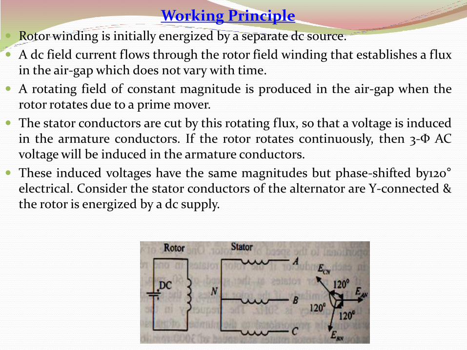
Working Principle Rotor winding is initially energized by a separate dc source.
A dc field current flows through the rotor field winding that establishes a fluxin the air-gap which does not vary with time.
A rotating field of constant magnitude is produced in the air-gap when therotor rotates due to a prime mover.
The stator conductors are cut by this rotating flux, so that a voltage is inducedin the armature conductors. If the rotor rotates continuously, then 3-Φ ACvoltage will be induced in the armature conductors.
These induced voltages have the same magnitudes but phase-shifted by120°electrical. Consider the stator conductors of the alternator are Υ-connected &the rotor is energized by a dc supply.
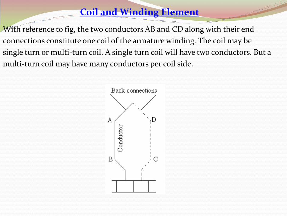
Coil and Winding Element
With reference to fig, the two conductors AB and CD along with their end
connections constitute one coil of the armature winding. The coil may be
single turn or multi-turn coil. A single turn coil will have two conductors. But a
multi-turn coil may have many conductors per coil side.

Full Pitch and Short Pitch Winding
The coils are arranged according to the number of slots/pole/phase in the
alternator. The two sides of a coil are placed in the slots with a span of 180°.
The span between two adjacent opposite poles is known as pole pitch (זp).
The winding consisting of coils having span,
which is equal to one pole pitch i.e. spanning over
180 electrical degrees, is known as full pitch winding.
The winding consisting of coils having span, which is less
than the full-pitch winding is called the short pitch winding.
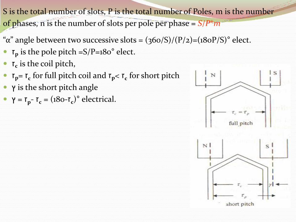
S is the total number of slots, P is the total number of Poles, m is the number
of phases, n is the number of slots per pole per phase = S/P*m
“α” angle between two successive slots = (360/S)/(P/2)=(180P/S)° elect.
pז is the pole pitch =S/P=180° elect.
cז is the coil pitch,
cז =pז for full pitch coil and זp< זc for short pitch
ץ is the short pitch angle
ץ -pז = cז °(cז-180) = electrical.
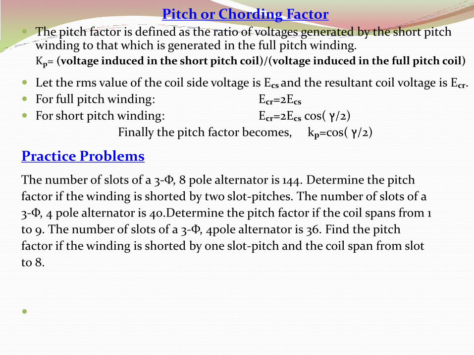
Pitch or Chording Factor The pitch factor is defined as the ratio of voltages generated by the short pitch
winding to that which is generated in the full pitch winding.Kp= (voltage induced in the short pitch coil)/(voltage induced in the full pitch coil)
Let the rms value of the coil side voltage is Ecs and the resultant coil voltage is Ecr.
For full pitch winding: Ecr=2Ecs
For short pitch winding: Ecr=2Ecs cos( 2/ץ)
Finally the pitch factor becomes, kp=cos( 2/ץ)
Practice Problems
The number of slots of a 3-Φ, 8 pole alternator is 144. Determine the pitch
factor if the winding is shorted by two slot-pitches. The number of slots of a
3-Φ, 4 pole alternator is 40.Determine the pitch factor if the coil spans from 1
to 9. The number of slots of a 3-Φ, 4pole alternator is 36. Find the pitch
factor if the winding is shorted by one slot-pitch and the coil span from slot
to 8.
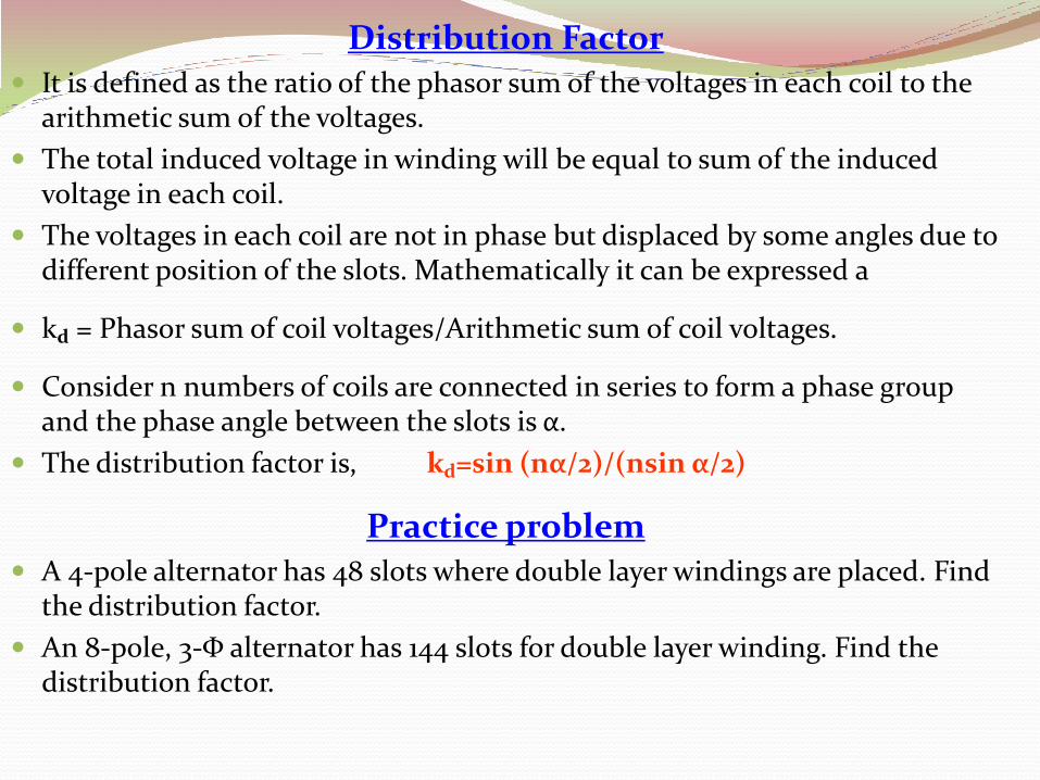
Distribution Factor It is defined as the ratio of the phasor sum of the voltages in each coil to the
arithmetic sum of the voltages.
The total induced voltage in winding will be equal to sum of the induced voltage in each coil.
The voltages in each coil are not in phase but displaced by some angles due to different position of the slots. Mathematically it can be expressed a
kd = Phasor sum of coil voltages/Arithmetic sum of coil voltages.
Consider n numbers of coils are connected in series to form a phase group and the phase angle between the slots is α.
The distribution factor is, kd=sin (nα/2)/(nsin α/2)
Practice problem A 4-pole alternator has 48 slots where double layer windings are placed. Find
the distribution factor.
An 8-pole, 3-Φ alternator has 144 slots for double layer winding. Find the distribution factor.
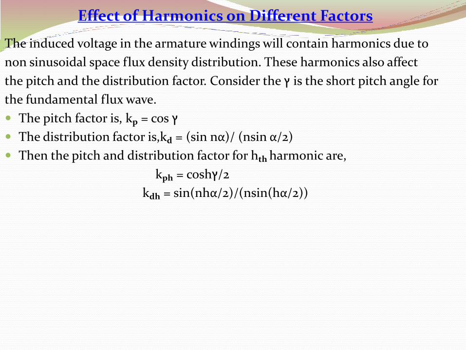
Effect of Harmonics on Different Factors
The induced voltage in the armature windings will contain harmonics due to
non sinusoidal space flux density distribution. These harmonics also affect
the pitch and the distribution factor. Consider the ץ is the short pitch angle for
the fundamental flux wave.
The pitch factor is, kp = cos ץ
The distribution factor is,kd = (sin nα)/ (nsin α/2)
Then the pitch and distribution factor for hth harmonic are,
kph = cosh2/ץ
kdh = sin(nhα/2)/(nsin(hα/2))
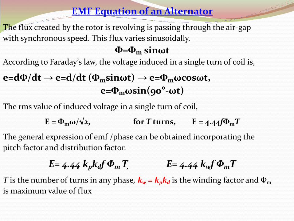
EMF Equation of an Alternator
The flux created by the rotor is revolving is passing through the air-gap
with synchronous speed. This flux varies sinusoidally.
Φ=Φm sinωtAccording to Faraday’s law, the voltage induced in a single turn of coil is,
e=dΦ/dt → e=d/dt (Φmsinωt) → e=Φmωcosωt,
e=Φmωsin(90°-ωt)
The rms value of induced voltage in a single turn of coil,
E = Φmω/√2, for T turns, E = 4.44fΦmT
The general expression of emf /phase can be obtained incorporating the
pitch factor and distribution factor.
E= 4.44 kpkdf Φm T, E= 4.44 kwf ΦmT
T is the number of turns in any phase, kw = kpkd is the winding factor and Φm
is maximum value of flux
Practice Problems
The number slots of a 3-phase, 12-pole, Y-connected alternator has 180.The
number of conductor per slot is 12 and the conductors are connected in
series. The coil is full-pitch winding and the flux per pole is 0.05Wb. If the
machine runs at a speed of 600rpm, determine the line voltage.
A 3-phase,50Hz, 4-pole, Y-connected alternator has 6 slots per phase. The
armature has double layers winding. The windings are arranged as 5
conductors per layer. The coil pitch is 5/6th of the full pitch and the flux per
pole is 0.05Wb. If the machine runs at a speed of 600rpm, determine the
phase voltage.
A 3-Φ, 50Hz, 10-pole, synchronous generator has 3 slots/phase. The
armature has double layers winding. The windings are arranged as 5
conductors/layer. The coil span is 150°. The value of the fundamental and 3rd
harmonic component of the flux is 0.05wb and 0.006wb. Determine the rms
value of the induced voltage per phase voltage.
The number slots of a 3-Φ, 4-pole, Υ-connected alternator has 36 slots. The
number of conductor per slot is 8 and the conductors are connected in
series. The coil is full pitch winding and the flux per pole is 0.06Wb. If the
machine runs at a speed of 600rpm, determine the line voltage.
The number slots/pole/phase of a 3-Φ, 50Hz, 4-pole, Y-connected alternator
is 4. The armature has double layers winding. The windings are arranged as
4 conductors/layer. The coil pitch is 3/4th of the full pitch and the flux/pole is
0.03Wb. Determine the phase and line voltage.
A 3-Φ, 60Hz, 6-pole, synchronous generator has 2 slots/ phase. The
armature has double layers winding. The windings are arranged as 4
conductors/layer. The coil span is 150°. The value of the fundamental of the
flux is 0.05Wb and third harmonic component of the flux is 30 percent of the
fundamental flux. Determine the rms value of the induced voltage/phase
voltage.
Equivalent circuit of a Synchronous Generator
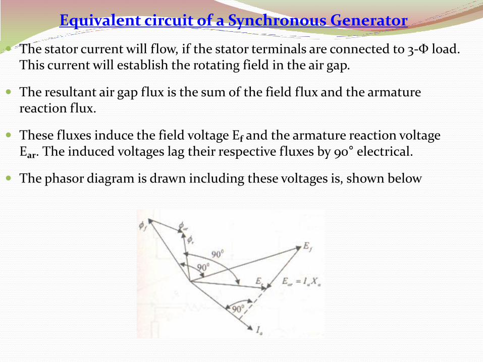
The stator current will flow, if the stator terminals are connected to 3-Φ load. This current will establish the rotating field in the air gap.
The resultant air gap flux is the sum of the field flux and the armature reaction flux.
These fluxes induce the field voltage Ef and the armature reaction voltage Ear. The induced voltages lag their respective fluxes by 90° electrical.
The phasor diagram is drawn including these voltages is, shown below
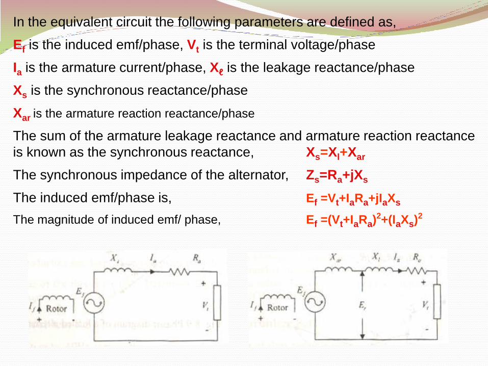
In the equivalent circuit the following parameters are defined as,
Ef is the induced emf/phase, Vt is the terminal voltage/phase
Ia is the armature current/phase, Xℓ is the leakage reactance/phase
Xs is the synchronous reactance/phase
Xar is the armature reaction reactance/phase
The sum of the armature leakage reactance and armature reaction reactance
is known as the synchronous reactance, Xs=Xl+Xar
The synchronous impedance of the alternator, Zs=Ra+jXs
The induced emf/phase is, Ef =Vt+IaRa+jIaXs
The magnitude of induced emf/ phase, Ef =(Vt+IaRa)2+(IaXs)2
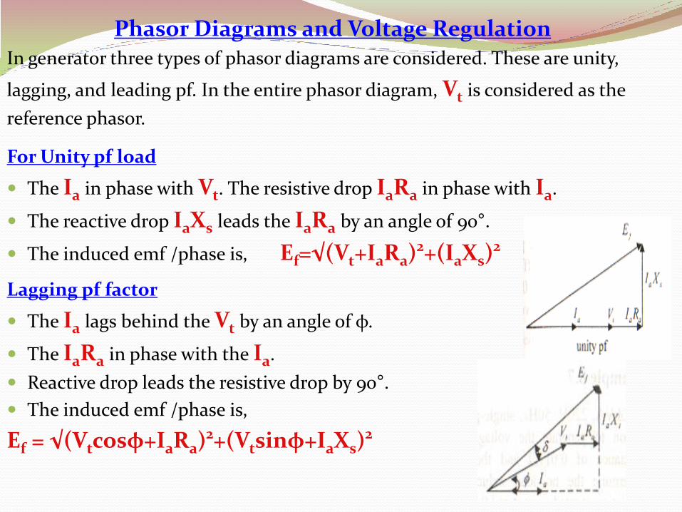
Phasor Diagrams and Voltage RegulationIn generator three types of phasor diagrams are considered. These are unity,
lagging, and leading pf. In the entire phasor diagram, Vt is considered as the
reference phasor.
For Unity pf load
The Ia in phase with Vt. The resistive drop IaRa in phase with Ia.
The reactive drop IaXs leads the IaRa by an angle of 90°.
The induced emf /phase is, Ef=√(Vt+IaRa)2+(IaXs)2
Lagging pf factor
The Ia lags behind the Vt by an angle of φ.
The IaRa in phase with the Ia.
Reactive drop leads the resistive drop by 90°.
The induced emf /phase is,
Ef = √(Vtcosφ+IaRa)2+(Vtsinφ+IaXs)2

Leading pf
Ia leads the Vt by an angle of φ and Ra in phase with the Ia.
Xs leads the resistive drop by an angle of 90°.
The induced emf /phase is,
Ef=√(Vtcosφ+IaRa)2+(Vtsinφ-IaXs)2
Voltage Regulation
It is the change in magnitude of the terminal voltage b/w no-load and full-load
conditions.
VR=(Vnℓ-Vfℓ)/Vfℓx100=(Ef-Vt)/Vfℓx100
Practice Problems
A 50kVA, 220V, 50Hz, 1-Φ alternator is using in the power station to generate the voltage. This alternator has the effective resistance of
0.010Ω and the synchronous reactance of 0.09Ω. Determine the no-load induced voltage/phase and voltage regulation at rated current and 0.85pf lagging.
A 3-Φ, 60kVA, 415V, Υ-connected, 50Hz alternator has an armature resistance of 0.2Ω and a synchronous reactance of 2.3Ω. Determine the no-load induced voltage/phase and the voltage regulation at unity power factor.
Tests of Synchronous Generator
The Ra of the alternator is determined by the voltmeter & ammeter method. Let R be
the resistance b/w terminals. For Υ-connection, the value of the Ra is
Ra+Ra=R=0.5 →Ra=0.5R , For Δ-connection, R= Ra║(Ra+Ra) →Ra=1.5R
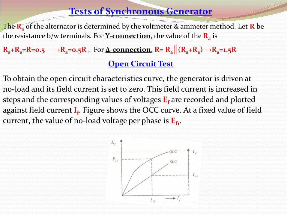
Open Circuit Test
To obtain the open circuit characteristics curve, the generator is driven at
no-load and its field current is set to zero. This field current is increased in
steps and the corresponding values of voltages Ef are recorded and plotted
against field current If. Figure shows the OCC curve. At a fixed value of field
current, the value of no-load voltage per phase is Ef1.
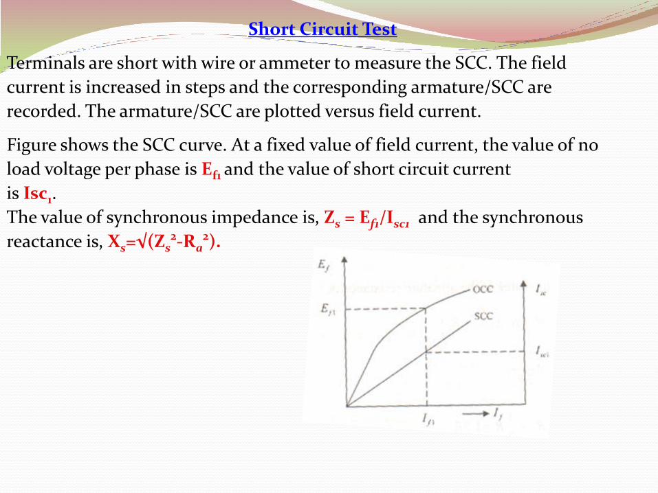
Short Circuit Test
Terminals are short with wire or ammeter to measure the SCC. The field
current is increased in steps and the corresponding armature/SCC are
recorded. The armature/SCC are plotted versus field current.
Figure shows the SCC curve. At a fixed value of field current, the value of no
load voltage per phase is Ef1 and the value of short circuit current
is Isc1.
The value of synchronous impedance is, Zs = Ef1/Isc1 and the synchronous
reactance is, Xs=√(Zs2-Ra
2).

Practice Problems
A 3-Φ, 50Hz, 33kV, Υ-connected alternator is installed. The Ra/phase is 0.54Ω. The
tests data are given: SC test: If =15A, voltage b/w lines is 415V and for OC test: If
=15A, short circuit current is 25A. Find the synchronous impedance, synchronous
reactance and full-load VR at 0.9 pf lagging.
A 3-Φ,100kVA, 50Hz, 11kV, Δ-connected alternator is installed. The per armature
resistance b/w two terminals is 0.24Ω. The tests data are : SC test: If = 25A, voltage
b/w lines is 400V and OC test: If = 25A, short circuit current is 40A. Find the
synchronous impedance, synchronous reactance & full-load VR at 0.85 pf lagging.
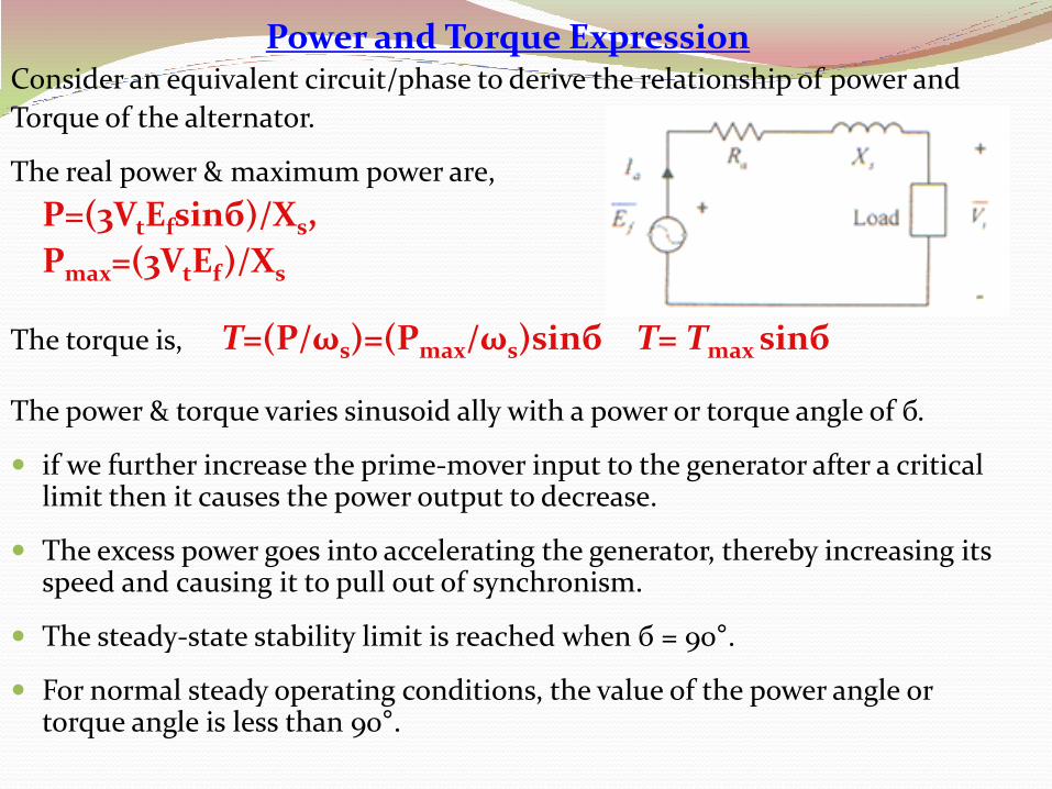
Power and Torque ExpressionConsider an equivalent circuit/phase to derive the relationship of power and
Torque of the alternator.
The real power & maximum power are,
P=(3VtEfsinб)/Xs,
Pmax=(3VtEf)/Xs
The torque is, T=(P/ωs)=(Pmax/ωs)sinб T= Tmax sinб
The power & torque varies sinusoid ally with a power or torque angle of б.
if we further increase the prime-mover input to the generator after a critical limit then it causes the power output to decrease.
The excess power goes into accelerating the generator, thereby increasing its speed and causing it to pull out of synchronism.
The steady-state stability limit is reached when б = 90°.
For normal steady operating conditions, the value of the power angle or torque angle is less than 90°.
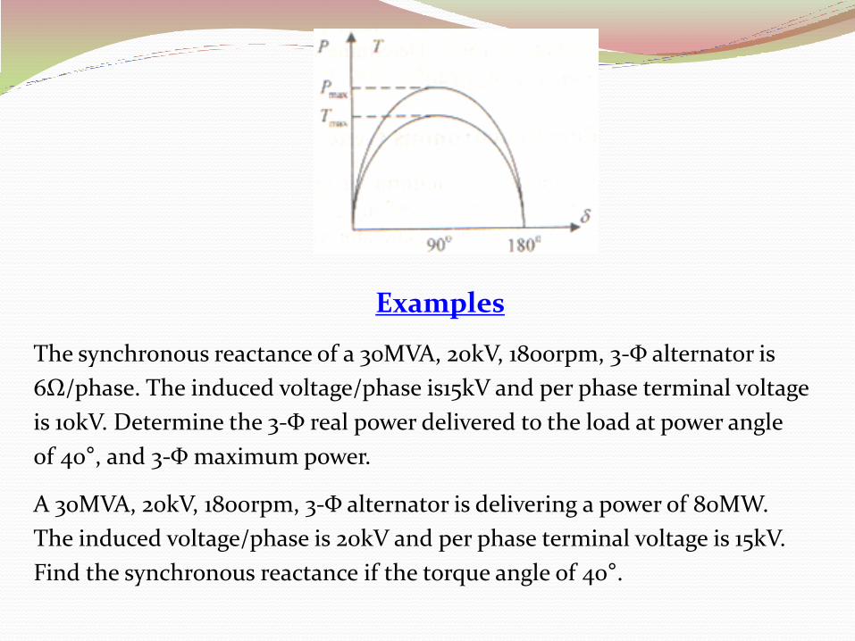
Examples
The synchronous reactance of a 30MVA, 20kV, 1800rpm, 3-Φ alternator is
6Ω/phase. The induced voltage/phase is15kV and per phase terminal voltage
is 10kV. Determine the 3-Φ real power delivered to the load at power angle
of 40°, and 3-Φ maximum power.
A 30MVA, 20kV, 1800rpm, 3-Φ alternator is delivering a power of 80MW.
The induced voltage/phase is 20kV and per phase terminal voltage is 15kV.
Find the synchronous reactance if the torque angle of 40°.

Parallel Operation of Alternator
In the power station, a number of alternators are connected in parallel to generate the sufficient amount of electrical power.
The connection of the parallel alternators with the common infinite bus of National Grid of WAPDA is known as synchronization.
The following conditions should be satisfied before making parallel connection: same terminal voltage, same frequency, same phase, same phase sequence.
Figure shows 2 generator with same load/torque characteristics areconnected in parallel across the load.
Let Vt is the terminal voltage, E1 is the Induced voltage/phase by alternator1
& E2 is the induced voltage by the alternator 2. The impedances and currentsare shown in figure.
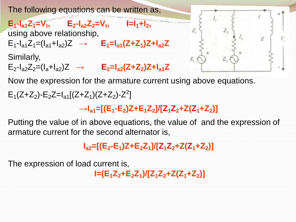
The following equations can be written as,
E1-Ia1Z1=Vt, E2-Ia2Z2=Vt, I=I1+I2,
using above relationship,
E1-Ia1Z1=(Ia1+Ia2)Z → E1=Ia1(Z+Z1)Z+Ia2Z
Similarly,
E2-Ia2Z2=(Ia+Ia2)Z → E2=Ia2(Z+Z2)Z+Ia1Z
Now the expression for the armature current using above equations.
E1(Z+Z2)-E2Z=Ia1[(Z+Z1)(Z+Z2)-Z2]
→Ia1=[(E1-E2)Z+E1Z2]/[Z1Z2+Z(Z1+Z2)]
Putting the value of in above equations, the value of and the expression of
armature current for the second alternator is,
Ia2=[(E2-E1)Z+E2Z1]/[Z1Z2+Z(Z1+Z2)]
The expression of load current is,
I=(E1Z2+E2Z1)/[Z1Z2+Z(Z1+Z2)]
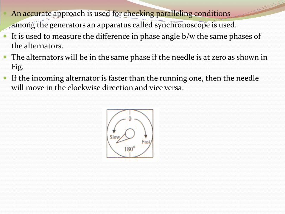
An accurate approach is used for checking paralleling conditions
among the generators an apparatus called synchronoscope is used.
It is used to measure the difference in phase angle b/w the same phases of the alternators.
The alternators will be in the same phase if the needle is at zero as shown in Fig.
If the incoming alternator is faster than the running one, then the needle will move in the clockwise direction and vice versa.
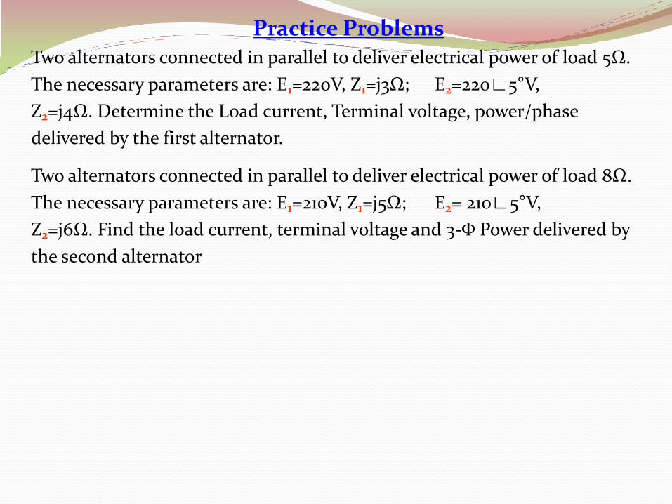
Practice Problems Two alternators connected in parallel to deliver electrical power of load 5Ω.
The necessary parameters are: E1=220V, Z1=j3Ω; E2=220∟5°V,
Z2=j4Ω. Determine the Load current, Terminal voltage, power/phase
delivered by the first alternator.
Two alternators connected in parallel to deliver electrical power of load 8Ω.
The necessary parameters are: E1=210V, Z1=j5Ω; E2= 210∟5°V,
Z2=j6Ω. Find the load current, terminal voltage and 3-Φ Power delivered by
the second alternator
True, Reactive, and Apparent power in an AC Circuit
We know that reactive loads such as inductors and capacitors dissipate zero
power, yet the fact that they drop voltage and draw current gives the deceptive
impression that they actually do dissipate power. This “phantom power” is
called reactive power, and it is measured in a unit called Volt-Amps-Reactive
(VAR), rather than watts. The mathematical symbol for reactive power is
(unfortunately) the capital letter Q.
The actual amount of power being used, or dissipated, in a circuit is called true
power, and it is measured in watts (symbolized by the capital letter P, as
always).
The combination of reactive power and true power is called apparent power,
and it is the product of a circuit's voltage and current, without reference to
phase angle. Apparent power is measured in the unit of Volt-Amps (VA) and is
symbolized by the capital letter S.
As a rule, true power is a function of a circuit's dissipative elements, usually
resistances (R). Reactive power is a function of a circuit's reactance (X).
Apparent power is a function of a circuit's total impedance (Z).
True, Reactive, and Apparent power in an AC Circuit
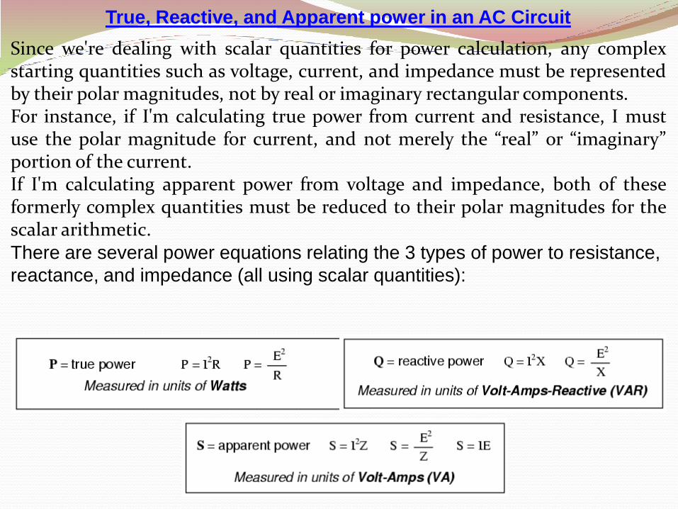
Since we're dealing with scalar quantities for power calculation, any complexstarting quantities such as voltage, current, and impedance must be representedby their polar magnitudes, not by real or imaginary rectangular components.For instance, if I'm calculating true power from current and resistance, I mustuse the polar magnitude for current, and not merely the “real” or “imaginary”portion of the current.If I'm calculating apparent power from voltage and impedance, both of theseformerly complex quantities must be reduced to their polar magnitudes for thescalar arithmetic.There are several power equations relating the 3 types of power to resistance,
reactance, and impedance (all using scalar quantities):

True, Reactive, and Apparent Power in an AC Circuit
Please note that there are two equations each for the calculation of true and
reactive power and three equations available for the calculation of apparent
power, P=IE being useful only for that purpose. Examine the following circuits
and see how these three types of power interrelate for: a purely resistive load,
a purely reactive load and a resistive/reactive load.
True, Reactive, and Apparent Power in an AC Circuit
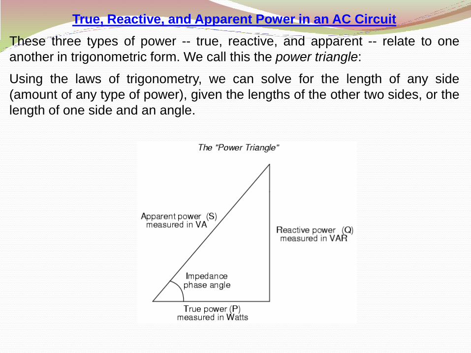
These three types of power -- true, reactive, and apparent -- relate to one
another in trigonometric form. We call this the power triangle:
Using the laws of trigonometry, we can solve for the length of any side
(amount of any type of power), given the lengths of the other two sides, or the
length of one side and an angle.
True, Reactive, and Apparent Power in an AC Circuit
REVIEW:
•Power dissipated by a load is referred to as true power. True power is
symbolized by the letter P and is measured in the unit of Watts (W).
•Power merely absorbed and returned in load due to its reactive properties is
referred to as reactive power. Reactive power is symbolized by the letter Q
and is measured in the unit of Volt-Amps-Reactive (VAR).
•Total power in an AC circuit, both dissipated and absorbed/returned is
referred to as apparent power. Apparent power is symbolized by the letter S
and is measured in the unit of Volt-Amps (VA).
•These three types of power are trigonometrically related to one another. In a
right triangle, P = adjacent length, Q = opposite length, and S = hypotenuse
length. The opposite angle is equal to the circuit's impedance (Z) phase
angle.
Related Documents