ech T Press Science Computers, Materials & Continua DOI:10.32604/cmc.2022.022556 Article Switched-Beam Optimization for an Indoor Visible Light Communication Using Genetic Algorithm Ladathunya Pumkaew, Monthippa Uthansakul * and Peerapong Uthansakul School of Telecommunication Engineering, Institute of Engineering, Suranaree University of Technology, Nakhon Ratchasima, 30000, Thailand * Corresponding Author: Monthippa Uthansakul. Email: [email protected] Received: 11 August 2021; Accepted: 15 September 2021 Abstract: Nowadays, Visible Light Communication (VLC) is an attractive alternative technology for wireless communication because it can use some simple Light Emitting Diodes (LEDs) instead of antennas. Typically, indoor VLC is designed to transmit only one dataset through multiple LED beams at a time. As a result, the number of users per unit of time (throughput) is relatively low. Therefore, this paper proposes the design of an indoor VLC system using switched-beam technique through computer simulation. The LED lamps are designed to be arranged in a circular array and the signal can be transmitted through the beam of each LED lamp with the method of separating the dataset to increase the number of simultaneous users for enhancing the indoor VLC. The coverage area is determined from the area where the communication can be performed at a location on the receiving plane with a Bit Error Rate less than or equal to the specified value based on coverage illuminance according to International Commission on Illumination (CIE) standards. In this paper, Genetic Algorithm is used to find the suitable solution for designing param- eters to achieve maximum coverage area. The results show that a Genetic Algorithm can be used to find a suitable solution and reduce the computational time approximately 382 min in proposed scenarios. Keywords: Visible light communication; genetic algorithm; optimization; light emitting diode 1 Introduction Visible Light Communication (VLC) is an interesting alternative technology because the cur- rent radio frequency communication system has limitations in data rate, insufficient bandwidth to increase the number of users, and interference among electromagnetic wave sources. So far, VLC technology demonstrates the next level of potential wireless communication in the near future because light can be easily used instead of using radio frequencies [1]. The VLC is one type of communication in which the data is transmitted by the modulation of light waves from the visible light spectrum with the wavelengths in the range of 380 nm–780 nm using LEDs. The reason for using LED to transmit data is because the LED is an electronic This work is licensed under a Creative Commons Attribution 4.0 International License, which permits unrestricted use, distribution, and reproduction in any medium, provided the original work is properly cited.

Welcome message from author
This document is posted to help you gain knowledge. Please leave a comment to let me know what you think about it! Share it to your friends and learn new things together.
Transcript

echT PressScienceComputers, Materials & ContinuaDOI:10.32604/cmc.2022.022556
Article
Switched-Beam Optimization for an Indoor Visible Light Communication UsingGenetic Algorithm
Ladathunya Pumkaew, Monthippa Uthansakul* and Peerapong Uthansakul
School of Telecommunication Engineering, Institute of Engineering, Suranaree University of Technology, NakhonRatchasima, 30000, Thailand
*Corresponding Author: Monthippa Uthansakul. Email: [email protected]: 11 August 2021; Accepted: 15 September 2021
Abstract: Nowadays, Visible Light Communication (VLC) is an attractivealternative technology for wireless communication because it can use somesimple Light Emitting Diodes (LEDs) instead of antennas. Typically, indoorVLC is designed to transmit only one dataset throughmultipleLEDbeams at atime.As a result, the number of users per unit of time (throughput) is relativelylow. Therefore, this paper proposes the design of an indoor VLC system usingswitched-beam technique through computer simulation. The LED lamps aredesigned to be arranged in a circular array and the signal can be transmittedthrough the beamof each LED lampwith themethodof separating the datasetto increase the number of simultaneous users for enhancing the indoor VLC.The coverage area is determined from the area where the communication canbe performed at a location on the receiving plane with a Bit Error Rate lessthan or equal to the specified value based on coverage illuminance accordingto International Commission on Illumination (CIE) standards. In this paper,Genetic Algorithm is used to find the suitable solution for designing param-eters to achieve maximum coverage area. The results show that a GeneticAlgorithmcan be used to find a suitable solution and reduce the computationaltime approximately 382 min in proposed scenarios.
Keywords: Visible light communication; genetic algorithm; optimization;light emitting diode
1 Introduction
Visible Light Communication (VLC) is an interesting alternative technology because the cur-rent radio frequency communication system has limitations in data rate, insufficient bandwidth toincrease the number of users, and interference among electromagnetic wave sources. So far, VLCtechnology demonstrates the next level of potential wireless communication in the near futurebecause light can be easily used instead of using radio frequencies [1].
The VLC is one type of communication in which the data is transmitted by the modulationof light waves from the visible light spectrum with the wavelengths in the range of 380 nm–780nm using LEDs. The reason for using LED to transmit data is because the LED is an electronic
This work is licensed under a Creative Commons Attribution 4.0 International License,which permits unrestricted use, distribution, and reproduction in any medium, providedthe original work is properly cited.

1548 CMC, 2022, vol.71, no.1
device that provides brightness, saves energy, and has a lifespan longer than traditional bulbs.This plays a significant role in smart lighting being able to provide both illuminations and alsocommunication at the same time [2]. Not only VLC has increased capacity and low latency butalso has the key property of LEDs that allows the VLC to be modulated at high frequenciesenough to achieve higher data rates. It’s a great opportunity to enhance the current wirelessinfrastructure, which can be applied in a wide range of applications such as scientific, industrial,commercial, and communication fields. These applications include indoor positioning, underwatercommunication and intelligent transportation system [3,4].
The structure of VLC consists of 3 main parts: transmitter, channel, and receiver, as shown inFig. 1 [5]. On the transmitting side, the data is conveyed to the system and then modulated to theLED, which is the transmitting device to convert the electrical signal into a light signal. The datais transmitted by the flashing of light through the channel. While transmitting, the transmitterand receiver must be in the Line Of Sight (LOS). In fact, there is a loss of signal quality due tothe interference caused by other ambient lights during transmission. This can be corrected by anoptical bandpass filter to reduce the interference. On the receiving side, the device used to receivesignal is a photodiode which detects light signal and converts to electrical signal. Afterward, thesignal is demodulated back to be data [6].
Figure 1: VLC structure
Light has been used for communication from the past to the present. For example, a photo-phone was invented in the late 19th century by Alexander Graham Bell. The photophone has beenconsidered as the beginning era of optical communication. The work started from sunlight reflec-tion on the glass surface of the transmission sector, in which the light waves vibrate according tothe user’s voice. After that, light is sent to the lens which is a reflective curved glass installed inthe receiver [7]. A novel method of establishing a secure and reliable communication link usingoptical wireless communication is achieved by separating signal transmission with two opticaltransmitters [8]. In 2000, LEDs gained a lot of attention in which they can be utilized in VLCwith the use of white LED for indoor communication [9]. Moreover, in 2011, the introductionof Light Fidelity (Li-Fi) was introduced as technology similar to Wi-Fi. However, it transmits asignal with light by changing the brightness or amplitude of LEDs. This can transmit only onedataset through the LED beam per user at a time. Li-Fi has been considered the first applicationof VLC [10].
The VLC can be categorized as indoor VLC, such as communication in the office room, onthe plane, or even in the hospital, etc., and outdoor VLC such as Vehicle-to-Vehicle communi-cations (V2V) or Vehicle-to-Infrastructure communication (V2I) [1]. Nowadays, many kinds of

CMC, 2022, vol.71, no.1 1549
researches have been designed to arrange LED arrays in various forms for performance enhance-ment, usually arranged in a square and circular shapes. The performance of square and circulararrangements was analyzed, and it was found that circular-array LED arrangement provides betteruniformity of illumination in terms of light distribution [11].
The optimal circular-array LED arrangement was presented to improve the uniformity ofIllumination for the VLC system [12]. The design has 16 white LEDs used in a room size of5× 5× 3 m3, with 4 LEDs in the corner and 1 LED in the middle of the room, surroundedby 11 LEDs arranged in a circular form. In the simulation, the radius of the circular array waschanged from 1.5 to 2.3 m in increments of 0.2 m. The results have shown that at a radius of 2.1m, the VLC system has the highest uniformity of illumination but still transmits only one datasetthrough the LED beam per user at a time.
In addition, the optical beamforming technique can be used for enhancing the VLC system.The Spatial Light Modulator (SLM) uses optical beamforming to control the LED beam to bedirectly focused on the desired target device at the receiver [13]. This prevents energy-wastingin unnecessary directions and can enhance the quality of the received signal. The SLM is anamplitude or phase-modulated device in which liquid crystal molecules are arranged inside [14].It can be controlled by a computer to adjust the voltage. When the voltage increases, the liquidcrystal molecules change, causing the phase to change. As a result, the direction of the beamcan be focused on the desired target device at the receiver. In the experiment, the communicationsignal was generated using a function generator and modulated from input data to LED. Then,the LED light was passed through a beam expander to control the beam size in the experimentand entered into the SLM. The SLM is controlled by a computer for giving the direction of thebeam to focus on the desired target device at the receiver. The results have shown that beforeusing optical beamforming, the received signal cannot be normally demodulated because the signalstrength is too weak. However, the signal strength as the same as Signal to Noise Ratio (SNR)increases compared to the original ones after using optical beamforming.
The optical beamforming can be applied to multiple access techniques such as Space DivisionMultiple Access (SDMA) or Time Division Multiple Access (TDMA) to support multiple users inreal situations [15]. The SDMA optical beamforming is the division of beams into different areas.It uses the SLM for controlling the LED beam to be focused on the target device. The use of theSDMA optical beamforming technique can support a larger number of users in which multipleusers can communicate with each other at the same time. However, the received signal strengthdecreases with the number of users. Moreover, for the TDMA optical beamforming, the beam isfocused on each target device at different times. This technique allows transmission signal at fullpotential, but the data rate decreases with the number of users.
Apparently, the use of optical beamforming techniques using SLM can significantly enhancecommunication performance. This can improve the quality of the received signal, but SLM devicesare quite expensive, which is a limitation in terms of cost.
From the literatures, most of the traditional indoor VLC system transmit only one datasetthrough the LED beam per user at a time. As a result, the number of users per unit of time(throughput) is low. Therefore, this paper proposes the design of an indoor VLC system usingswitched-beam technique through MATLAB programing. The LED lamps are designed to bearranged in a circular array. The signal can be transmitted through the beam of each LED lampwith the method of separating the dataset to increase the number of simultaneous users enhancingthe indoor VLC as shown in Fig 2. Fig. 2a shows a traditional indoor VLC system and Fig. 2b

1550 CMC, 2022, vol.71, no.1
shows the proposed design. The coverage area is determined from the area where communicationcan be performed at a location on the receiving plane with a Bit Error Rate less than or equal to10−3 based on coverage illuminance that must cover greater than or equal to 300 lux accordingto International Commission on Illumination (CIE) standards.
Figure 2: The proposed design of an indoor VLC system using switched-beams. (a) The traditionalindoor VLC system transmits only one dataset; (b) The proposed design separates dataset toincrease the number of simultaneous users
The most popular method to optimize the uniform illuminance distribution in VLC systemis based on specific location orientation of LED or the power allocation [16,17]. In these con-ventional optimizations, some parameter values are selected for calculation. It can be inferredthat optimization will have better performance when all parameter values in the possible datarange are selected. In order to find the optimal values in the large search space, intelligentoptimization algorithms, such as convex optimization algorithm, evolutionary algorithm and fishswarm algorithm are preferred to reduce the computational process [18–20].
The calculation in this paper is considerably complex because the system has multiobjectiveoptimization adjusting the designing parameters depending on both coverage area and conditionof coverage illuminance. Therefore, heuristic optimization technique is applied to reduce complexcalculation for finding the optimal path. Two types of optimization techniques are proposed;exhaustive search method and heuristic method. The exhaustive search examines every searchpoint within the search space in order to get accurate optimal results but it takes a long timeto calculate. So far, Genetic Algorithm is the most popular heuristic method. It is adopted tofind the suitable solution for designing parameters to achieve maximum coverage area as it caneffectively solve problems in large and complex data sets. Also, it can be used in VLC optimizationproblem [21–24]. The performance of Genetic Algorithm is analyzed comparing to the resultsobtained from an exhaustive search.
The remainder of this paper is as follows. Firstly, the section of materials and methodsdiscusses an array LED design, a proposed algorithm, and the simulation setup. The followingsection is results and discussion. Finally, the conclusion is given.

CMC, 2022, vol.71, no.1 1551
2 Materials and Methods
2.1 System ModelIn this subsection, the calculation of the horizontal illuminance, the received optical power
of directed light, Signal to Interference plus Noise Ratio (SINR), Bit Error Rate (BER), and theproposed LED-array design are discussed.
The horizontal illuminance: The illuminance expresses the distribution of an illuminatedsurface. A horizontal illuminance Ehor is given as [25]:
Ehor=I(∅)
D2d
· cos(�) (1)
where Dd is distance between a transmitter and a receiver, ∅ is the angle of irradiance, � isthe angle of incidence, and I(∅) is the luminous intensity according to the Lambertian radiationproperties of LED. This can be calculated as:
I(∅)= I(0)cosm(∅) (2)
where I(0) is the center luminous intensity of an LED and m is the order of Lambertian. Thiscan be calculated as:
m= −ln(2)ln(cos(∅1/2)) (3)
where ∅1/2 is the semi-angle at the half power of LED.
The received optical power: In this paper, the only effect of directed light is considered,excluding the reflective light by walls. The received optical power Pr can be calculated as:
Pr =H(0) ·Pt (4)
where Pt is the transmitted optical power and H(0) is the channel DC gain. This is given as [25]:
H(0)=
⎧⎪⎪⎪⎪⎨⎪⎪⎪⎪⎩
(m+ 1)A
2πD2d
cosm(φ)Ts(�)g(�) cos(�),
0≤� ≤�c,0,
� > �c,
(5)
where A is the physical area of photodiode, m is the order of Lambertian, Dd is distance betweena transmitter and a receiver, ∅ is the angle of irradiance, � is the angle of incidence, Ts is thegain of optical filter, �c is the field of view of the receiver, and g(�) is the gain of an opticalconnector. This is given as:
g(�)=⎧⎨⎩
n2
sin2�c, 0≤� ≤�c,
0, 0≥�c,(6)
where n is the refractive index.

1552 CMC, 2022, vol.71, no.1
Signal to Interference Plus Noise Ratio: We design an array of LEDs to transmit differentdata for increasing the number of simultaneous users who can access the system at the same time.It results in interference among LED beams. The SINR can be calculated as [26,27]:
SINR= (RPr,x)2
(RΣi �=xPr,i)2+ σ 2total
(7)
where R is the photodiode responsivity, Pr is the received optical power, and σ 2total is the total
noise variance. This can be calculated as:
σ 2total = σ 2
shot+ σ 2amplifier (8)
where σ 2shot is the shot noise variance and σ 2
amplifier is the amplifier noise variance, which are
given by:
σ 2shot= 2qR(Pr+Pn)Bn (9)
σ 2amplifier= i2amplifierBa (10)
where Pn is the noise power of ambient light, q is the electron mass as 1.602× 10⁻¹⁹ C, i is theamplifier noise density, Ba is the amplifier bandwidth and Bn is the noise-bandwidth. This can becalculated as:
Bn= I2Rb (11)
where I2 is noise bandwidth factor and Rb is data rate.
Finally, The Bit Error Rate: BER can be calculated as [27]:
BER=Q(√
SINR)
(12)
where Q(x) is the probability that a standard normal random variable takes a value larger than x
The function Q(x)= 1√2π
∞∫xe−y22 dy.
The accurate BER performance for wireless optical communication and indoor VLC systemrequires a BER of 10−3 [28]. In this paper, we consider the coverage area by determining fromthe area where communication can be performed at BER less than or equal to 10−3.
LED-Array design: In the design of the LED installation, it is necessary to consider forthe sufficient illumination, which must have the illuminance at least 300–2000 lux according toCIE [29]. Typically, single LED installation is not popular because of insufficient illuminationaccording to the CIE standard. Therefore, multiple LEDs must be installed in an array arrange-ment. This paper proposes the design of an indoor VLC system using switched-beam techniquethrough MATLAB programing by designing the circular array LED arrangements with whiteLEDs. One LED in the center of the room is surrounded by remaining LEDs that tilt out fromthe center. The signal can be transmitted through the beam of each LED lamp with the method ofseparating the dataset to increase the number of users who can simultaneously access the systemfor enhancing the indoor VLC.
CMC, 2022, vol.71, no.1 1553
The center LED: One LED is designed to be placed in the center of the area, as shown inFig. 3a. The angle of irradiance can be calculated as:
∅= cos−1(hD
)(13)
where ∅ is the angle of irradiance, h is height between source and receiver plane, and D is distancebetween LED and user at a receiver plane.
Figure 3: An LED-array design. (a) The design of center LED; (b) The design of surroundingLED I; (c) The design of surrounding LED II
The surrounding LED: The remaining LEDs are designed to be tilted out from the centerLED and arranged in a circular LED array. As a result, the angle of irradiance is changed asshown in Fig. 3b. The new angle of irradiance can be calculated as:
cos α =(D2 +Y2−B2
2DY
)(14)
where α is the new angle of irradiance, D is distance between LED and user at a receiver plane,Y is distance between LED and the beam coordinate, and B is distance between the user at areceiver plane and the beam coordinate.
The beam coordinate is the coordinate in which the center beam of the LED falls on thereceiving plane, as shown in Fig. 3c. This can be calculated as:
Beam= r+L (15)
where r is the radius of circular array LED, and L is the distance between the beam coordinateand the coordinate on the receiving plane, which is perpendicular to the LED. This can becalculated as:
L= tan θ · h (16)
where θ is the inclination angle (z-angle), and h is height between source and receiver plane.

1554 CMC, 2022, vol.71, no.1
Fig. 3a shows a design of center LED, Fig. 3b shows a design of surrounding LED I, andFig. 3c shows a design of surrounding LED II.
After designing the LED array, it is necessary to find the solution of designing parametersto achieve maximum possible communication area, also known as maximum coverage area. Thispaper adopts Genetic Algorithm to find the suitable solution for designing parameters withvarious simulation scenarios.
The simulation parameters in MATLAB programming are shown in Tab. 1. The heightbetween source and receiver plane is approximately 2.15 m [12]. The area sizes are the commonlyused standard size. A single LED is generally power used at 7 and 10 watts. As a result, thenumber of LEDs array should be used at 8, 9 and 12 LEDs for the sufficient illumination.Moreover, the designed parameters for the Genetic Algorithm to find the suitable solution are asfollows: 1. z-angle is the inclination angle in which the surrounding LED are inclined from thecenter LED, 2. Semi-angle at half power is the angle of a diffusing lens covering an LED, and3. Radius of LED array.
Table 1: The simulation parameters
Parameters Values
The number of LED array 8, 9, 12Single LED power (Watt) 7, 10Area size (m3) 5× 5× 3, 4× 5×3, 6× 6× 3Height between source and receiver plane (m) 2.15Photodiode area (cm2) 1Refractive index at PD 1.5Photodiode responsivity (R) 0.55Field of view (FOV) (degree) 60
2.2 AlgorithmThis paper adopts a Genetic Algorithm to find the suitable solution for designing parameters
mentioned above of each simulation scenario to achieve maximum coverage area. This is deter-mined from the area where communication can be performed at BER less than or equal to 10−3
based on coverage illuminance that must cover greater than or equal 300 lux according to CIEstandards. Moreover, Genetic Algorithm performance is analyzed by comparing the results withan exhaustive search.
2.2.1 Exhaustive SearchThe exhaustive search is an algorithm that examines every search point inside the search
region. However, a large amount of computation is required. As a result, the algorithm has lowefficiency because of a very large search space [30]. Therefore, several fast algorithms have beenproposed to save computation and enhance performance.
2.2.2 Genetic AlgorithmA Genetic Algorithm (GA) is a method for solving optimization problems based on a natural
selection process that mimics biological evolution. GA was developed by John Holland and his

CMC, 2022, vol.71, no.1 1555
assistant in 1975 [31]. The advantage of this algorithm is the tolerance of errors in finding answersfrom complex sources which is difficult to be modelled using mathematical equations. For thisreason, GA has become one of the most widely used optimization algorithms [32,33].
2.2.3 Genetic Algorithm DesignThe GA can be divided into five processes as follows: 1. Initiation 2. Fitness Function 3.
Selection 4. Crossover and 5. Mutation. Fig. 4 starts from:
(1) Initiation: The process begins with determining search space for the solution of designedparameters, which consists of
1. z-angle is the inclination angle in which the surrounding LEDs are inclined fromthe center LED. It is in the range of 1–70 degrees in the increments of 1 degree.
2. semi-angle at half power is the angle of a diffusing lens covering an LED. It isin the range of 10–90 degrees in the increments of 5 degrees.
3. radius of LED array. It is in the range of 0.1–1 meters in the increments of 0.1meters.
The range of z-angle and radius of LED array are determined to be appropriate for the sizeof the room. It is considered that the LED beam can cover the entire area of the room. For semi-angle at half power range, the possible value of this angle is described in many scenarios [34–36].Moreover, this angle can reach up to 90 degrees due to the limitation of LED.
Then, GA performs an individual element randomization which is called a population fromthe search space. Each individual element (chromosome) contains the solution of designedparameters (genes) as shown in Fig. 5.
2. Fitness Function: This process begins with determining the ability of an individual elementto compete with other individual elements. Each individual element (chromosome) is randomizedby GA which is substituted in the Fitness Function to find the coverage area based on coverageilluminance according to CIE standards.
3. Selection: This process begins with selecting the fittest individual elements and passingtheir genes to the next generation. Individual elements with high fitness have more chances to beselected for reproduction. This step selects the individual element with the maximum coverage areato match, and prepare for crossover by determining the heavy weight for an individual elementwith a large coverage area to increase the chances of finding a better coverage area. Then, twopairs of individual elements (parents) are randomized based on weight for crossover to find thenext generation.
4. Crossover: When each pair of parents is matched, a crossover point is randomized withinthe Genes by determining the crossover point in point 1 or 2. For example, at crossover point 1,two offspring appeared by the exchange of their parent genes becomes the next generation. Thepopulation has a fixed size. When the new generations are formed, individual elements with theleast fitness are eliminated, providing space for a new generation.
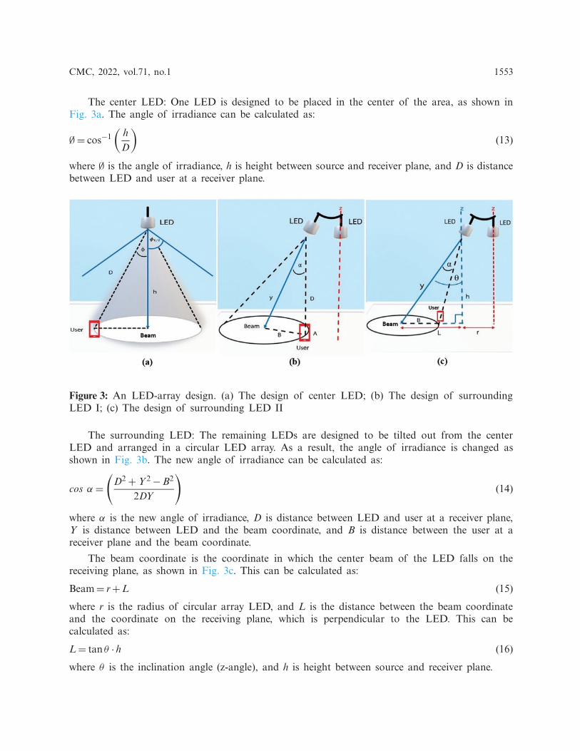
5. Mutation: Some of genes can be subjected to a mutation with a low random probability incertain new offspring. This increases the chances of finding new and better values by randomizingthe chance of mutation at every gene. If any gene has a chance of mutation, the values in thatrange of parameters will be randomized again. Moreover, each new generation is better than theprevious generation, as shown in Fig. 6.

1556 CMC, 2022, vol.71, no.1
The final process of GA brings a new generation back to Fitness Function for calculatingthe coverage area. Then, it checks if the maximum of duplicated coverage area is greater thanor equal to five times. Also, if the accuracy is greater than or equal to 30%, the algorithm willterminate. The result is the suitable solution of designed parameters.
NO
YESES If maximum duplicated coverage area ≥ 5 times && accuracy
≥ 30%
Start
Initiation
Fitness Function
Selection
Crossover
Mutation
End
Figure 4: The flow chart of genetic algorithm processes
Figure 5: The initiation process of genetic algorithm design
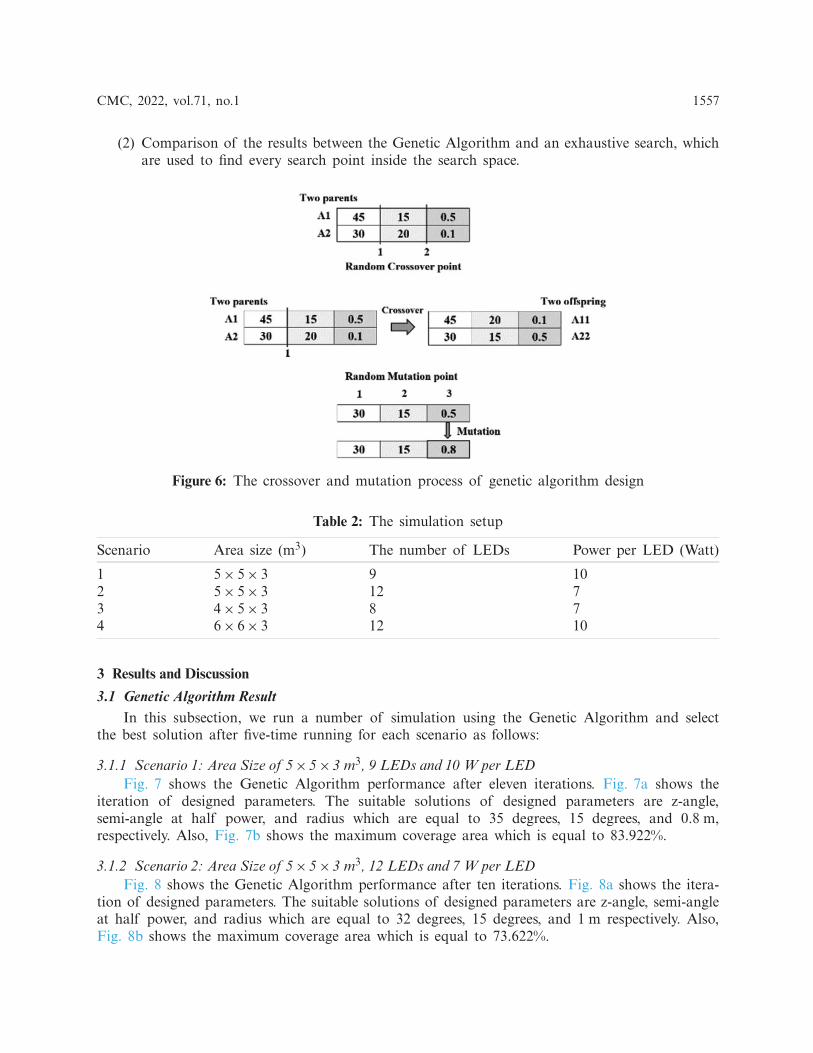
2.3 Simulation SetupThe simulation is designed for four scenarios as shown in Tab. 2, where the commonly used
standard area sizes, the number and power of the LEDs are different. The results are divided intotwo cases:
(1) The results from the adopted Genetic Algorithm which is used to find the solution fordesigning parameters mentioned above to achieve maximum coverage area. This is deter-mined from the area where communication can be performed with a BER less than orequal to 10−3 based on coverage illuminance which must cover greater than or equal to300 lux according to CIE standards.
CMC, 2022, vol.71, no.1 1557
(2) Comparison of the results between the Genetic Algorithm and an exhaustive search, whichare used to find every search point inside the search space.
Figure 6: The crossover and mutation process of genetic algorithm design
Table 2: The simulation setup
Scenario Area size (m3) The number of LEDs Power per LED (Watt)
1 5× 5× 3 9 102 5× 5× 3 12 73 4× 5× 3 8 74 6× 6× 3 12 10
3 Results and Discussion
3.1 Genetic Algorithm ResultIn this subsection, we run a number of simulation using the Genetic Algorithm and select
the best solution after five-time running for each scenario as follows:
3.1.1 Scenario 1: Area Size of 5× 5× 3 m3, 9 LEDs and 10 W per LEDFig. 7 shows the Genetic Algorithm performance after eleven iterations. Fig. 7a shows the
iteration of designed parameters. The suitable solutions of designed parameters are z-angle,semi-angle at half power, and radius which are equal to 35 degrees, 15 degrees, and 0.8 m,respectively. Also, Fig. 7b shows the maximum coverage area which is equal to 83.922%.
3.1.2 Scenario 2: Area Size of 5× 5× 3 m3, 12 LEDs and 7 W per LEDFig. 8 shows the Genetic Algorithm performance after ten iterations. Fig. 8a shows the itera-
tion of designed parameters. The suitable solutions of designed parameters are z-angle, semi-angleat half power, and radius which are equal to 32 degrees, 15 degrees, and 1 m respectively. Also,Fig. 8b shows the maximum coverage area which is equal to 73.622%.

1558 CMC, 2022, vol.71, no.1
Figure 7: Genetic Algorithm Performance of scenario 1. (a) The iteration of designed parametersis as follows z-angle = 35 degrees, semi-angle at half power 15 degrees and radius = 0.8 m. (b)The maximum coverage area = 83.922%
Figure 8: Genetic Algorithm Performance of scenario 2. (a) The iteration of designed parametersis as follows z-angle = 32 degrees, semi-angle at half power 15 degrees and radius = 1 m. (b)The maximum coverage area = 73.622%
3.1.3 Scenario 3: Area Size of 4× 5× 3 m3, 8 LEDs and 7 W per LEDFig. 9 shows the Genetic Algorithm performance after eight iterations. Fig. 9a shows the
iteration of designed parameters. The suitable solutions of designed parameters are z-angle,semi-angle at half power, and radius which are equal to 41 degrees, 20 degrees, and 1 mrespectively. Also, Fig. 9b shows the maximum coverage area which is equal to 78.181%.

CMC, 2022, vol.71, no.1 1559
3.1.4 Scenario 4: Area Size of 6× 6× 3 m3, 12 LEDs and 10 W per LEDFig. 10 shows the Genetic Algorithm performance after seven iterations. Fig. 10a shows
the iteration of designed parameters. The suitable solutions of designed parameters are z-angle,semi-angle at half power, and radius which are equal to 44 degrees, 15 degrees, and 0.6 mrespectively. Also, Fig. 10b shows the maximum coverage area which is equal to 73.677%.
Figure 9: Genetic Algorithm Performance of scenario 3. (a) The iteration of designed parametersis as follows z-angle = 41 degrees, semi-angle at half power 20 degrees and radius = 1 m. (b)The maximum coverage area = 78.181%
Figure 10: Genetic Algorithm Performance of scenario 4. (a) The iteration of designed parametersis as follows z-angle = 44 degrees, semi-angle at half power 15 degrees and radius = 0.6 m. (b)The maximum coverage area = 73.677%

1560 CMC, 2022, vol.71, no.1
From 4 scenarios, for GA cases, each parameter in the figure is adjusted because GA istrying to adapt itself to the suitable solution of designed parameters, which achieves the maximumcoverage area. Also, we can see that ever-increasing coverage area is obtained in each iterationuntil reaching the highest value. So, GA can find a suitable solution of designed parameters toachieve maximum coverage area.
3.2 Comparison Between an Exhaustive Search and Genetic AlgorithmTabs. 3–6 show the comparison between both algorithms, and they produce the same best
results. The exhaustive search finds the solution from the search space. It takes up to 480 min toselect a suitable solution which achieves the maximum coverage in each scenario, but the GeneticAlgorithm finds the suitable solution by reducing the computational time which takes less timethan an exhaustive search approximately 382 min in the proposed scenarios.
3.2.1 Scenario 1
Table 3: Comparison between an exhaustive search and a Genetic Algorithm in scenario 1
Solution Algorithm
Exhaustive search Genetic Algorithm
z-angle (◦) 35 35Semi-angle (◦) 15 15Radius (m) 0.8 0.8Coverage area (%) 83.922 83.922Time (minute) 480 87
3.2.2 Scenario 2
Table 4: Comparison between an exhaustive search and a Genetic Algorithm in scenario 2
Solution Algorithm
Exhaustive search Genetic Algorithm
z-angle (◦) 32 32Semi-angle (◦) 15 15Radius (m) 1 1Coverage area (%) 73.622 73.622Time (minute) 480 87

CMC, 2022, vol.71, no.1 1561
3.2.3 Scenario 3
Table 5: Comparison between an exhaustive search and a Genetic Algorithm in scenario 3
Solution Algorithm
Exhaustive search Genetic Algorithm
z-angle (◦) 41 41Semi-angle (◦) 20 20Radius (m) 1 1Coverage area (%) 78.181 78.181Time (minute) 480 61
3.2.4 Scenario 4
Table 6: Comparison between an exhaustive search and a Genetic Algorithm in scenario 4
Solution Algorithm
Exhaustive search Genetic Algorithm
z-angle (◦) 44 44Semi-angle (◦) 15 15Radius (m) 0.6 0.6Coverage area (%) 73.677 73.677Time (minute) 480 157
Also, both algorithms provide coverage illuminance equal to 100%, which has the distributionof illuminance greater than or equal to 300 lux according to the CIE standards in every scenario,as shown in Fig. 11.
Figs. 11a–11d show the distribution of illuminance for scenarios 1, 2, 3 and 4, respectively.
The coverage area is determined from the area where the communication can be performedon the receiving plane with a BER less than or equal to 10−3 as shown in Fig. 12. After usingGA to find the suitable solution, the coverage area is equal to 83.922%, 73.622%, 78.181%, and73.677% in which the system can support up to 9, 12, 8, and 12 simultaneous users, as shownin Figs. 12a–12drespectively. However, the interference among the light of LED beams is foundin some areas, which is the position on the receiving plane with a BER greater than 10−3. As aresult, users are unable to communicate in this interference area.

1562 CMC, 2022, vol.71, no.1
Figs. 12a–12d show the distribution of BER for scenarios 1, 2, 3 and 4, respectively.
Therefore, this paper proposes a method to increase the coverage area and reduce interferenceusing the switched-beam technique. For example, Scenario 1 can support up to 9 simultaneoususers, as shown in Fig. 13a. The position on the receiving plane with a BER greater than 10−3 isthe interference area. If users want to communicate in the interference area. This can be solvedby incorporating an LED beam from the closest LED beam to send data to users, as shown inFigs. 13b and 13c. Not only the switched-beam technique can provide performance enhancementof communication with an increased coverage area, but they also can effectively communicate inthe interference area. However, this result indicates the loss of one user when combining the LEDbeams at a time.
Figure 11: The distribution of illuminance, which provide coverage illuminance equal to 100%. (a)The distribution of illuminance for scenarios 1; (b) The distribution of illuminance for scenarios2; (c) The distribution of illuminance for scenarios 3; (d) The distribution of illuminance forscenarios 4
Fig. 13a shows a regular switched-beam, Fig. 13b shows the incorporating of an LED beamin two positions, and Fig. 13c shows the incorporating of an LED beam in three positions.

CMC, 2022, vol.71, no.1 1563
The coverage area increases from 83.922% to 86.496% and 88.027%, as shown in Fig. 13a–13c, respectively. This switched-beam technique provides a good performance for all scenarios.
Figure 12: The distribution of Bit Error Rate, which represent the coverage area. (a) The coveragearea = 83.922% in scenarios 1; (b) The coverage area = 73.622% in scenarios 2; (c) The coveragearea = 78.181% in scenarios 3; (d) The coverage area = 73.677% in scenarios 4

1564 CMC, 2022, vol.71, no.1
Figure 13: Example of the proposed method to increase the coverage area in scenario 1. (a) Theregular switched-beam technique (b) The incorporating of an LED beam in two positions (c) Theincorporating of an LED beam in three positions
4 Conclusions
This paper has presented the design of an indoor VLC system using the switched-beamtechnique through MATLAB programing, which has designed the LEDs to be arranged in acircular array. The communication is performed through the beam of each LED. The GeneticAlgorithm is adopted to find the suitable solution for designing parameters. From the simulationresults, a Genetic Algorithm can be used to find the suitable solution for designing parameters ofeach simulation scenario with less computational time than an exhaustive search approximately382 min in proposed scenarios. Also, the maximum coverage area based on coverage illuminanceaccording to the CIE standards can be achieved. Moreover, the switched-beam technique canenhance indoor VLC by increasing the number of simultaneous users and the coverage area.
Funding Statement: This work was supported by Suranaree University Technology, NakhonRatchasima, Thailand.
Conflicts of Interest: The authors declare that they have no conflicts of interest to report regardingthe present study.
References[1] P. Kocharoen, “Visible light communication: Importance and Thai preparations,” in Procedia Computer
Science, Chiang Mai, Thailand, pp. 51–54, 2016.[2] L. E. M. Matheus, A. B. Vieira, L. F. M. Vieira, M. A. M. Vieira and O. Gnawali, “Visible light
communication: Concepts, applications and challenges,” IEEE Communications Surveys & Tutorials, vol.21, no. 4, pp. 3204–3237, 2019.
[3] A. Jovicic, J. Li and T. Richardson, “Visible light communication: Opportunities, challenges and thepath to market,” IEEE Communications Magazine, vol. 51, no. 12, pp. 26–32, 2013.
CMC, 2022, vol.71, no.1 1565
[4] M. Saadi, T. Ahmad, M. K. Saleem and L. Wuttisittikulkij, “Visible light communication–an architec-tural perspective on the applications and data rate improvement strategies,” Transactions on EmergingTelecommunications Technologies, vol. 30, no. 2, pp. e3436, 2019.
[5] A. R. Ndjiongue, H. C. Ferreira and T. M. N. Ngatched, “Visible light communications (VLC)technology,” in Wiley Encyclopedia of Electrical and Electronics Engineering, Johannesburg, South Africa:Wiley Online Library, pp. 1–15, 2000.
[6] M. Saadi, L. Wuttisittikulkij, Y. Zhao and P. Sangwongngam, “Visible light communication: Opportu-nities, challenges and channel models,” International Journal of Electronics & Informatics, vol. 2, no. 1,pp. 1–11, 2013.
[7] A. G. Bell, “The photophone,” Science, vol. 1, no. 11, pp. 130–134, 1880.[8] M. Saadi, A. Bajpai, Y. Zhao, P. Sangwongngam and L. Wuttisittikulkij, “Design and implementation
of secure and reliable communication using optical wireless communication,” Frequenz, vol. 68, no.11–12, pp. 501–509, 2014.
[9] Y. Tanaka, T. Komine, S. Haruyama and M. Nakagawa, “Indoor visible light data transmission systemutilizing white LED lights,” IEICE Transactions on Communications, vol. 86, no. 8, pp. 2440–2454, 2003.
[10] H. Haas, L. Yin, C. Chen, S. Videv, D. Parol et al., “Introduction to indoor networking concepts andchallenges in liFi,” Journal of Optical Communications and Networking, vol. 12, no. 2, pp. A190–A203,2020.
[11] M. T. Niaz, F. Imdad, S. Kim and H. S. Kim, “Deployment methods of visible light communicationlights for energy efficient buildings,” Optical Engineering, vol. 55, no. 10, pp. 106113, 2016.
[12] P. Priyanka, M. Singh, H. S. Gill, S. Kaur and M. L. Singh, “Improvement of uniformity of illumina-tion for circular LED arrangement in VLC system,” in 2018 Int. Conf. on Recent Innovations in Electrical,Electronics & Communication Engineering (ICRIEECE), Bhubaneswar, India, pp. 2214–2217, 2018.
[13] S. Kim and S. Kim, “Performance improvement of visible light communications using optical beam-forming,” in 2013 Fifth Int. Conf. on Ubiquitous and Future Networks (ICUFN), Da Nang, Vietnam, pp.362–365, 2013.
[14] J. Remenyi, P. Varhegyi, L. Domjan, P. Koppa and E. Lorincz, “Amplitude, phase, and hybrid ternarymodulation modes of a twisted-nematic liquid-crystal display at ∼400 nm,” Applied Optics, vol. 42, no.17, pp. 3428–3434, 2003.
[15] S. M. Kim, “Visible light communication employing optical beamforming: A review,” Current Opticsand Photonics, vol. 2, no. 4, pp. 308–314, 2018.
[16] T. H. Do, J. Hwang and M. Yoo, “Analysis of the effects of LED direction on the performance ofvisible light communication system,” Photonic Network Communications, vol. 25, no. 1, pp. 60–72, 2013.
[17] L. A. Azizan, M. S. Ab-Rahman, M. R. Hassan, A. A. A. Bakar and R. Nordin, “Optimizationof signal-to-noise ratio for wireless light-emitting diode communication in modern lighting layouts,”Optical Engineering, vol. 53, no. 4, pp. 045103, 2014.
[18] G. P. Varma, “Optimum power allocation for uniform illuminance in indoor visible light communica-tion,” Optics Express, vol. 26, no. 7, pp. 8679–8689, 2018.
[19] J. Ding, Z. Huang and Y. Ji, “Evolutionary algorithm based power coverage optimization for visiblelight communications,” IEEE Communications Letters, vol. 16, no. 4, pp. 439–441, 2012.
[20] W. Jiaan, X. Ancheng, J. Jintao and G. Linyang, “Optimization lighting layout of indoor visible lightcommunication system based on improved artificial fish swarm algorithm,” Journal of Optics, vol. 22,no. 3, pp. 035701, 2020.
[21] M. Kumar, M. Husain, N. Upreti and D. Gupta, “Genetic algorithm: Review and application,”Available at SSRN 3529843, vol. 2, no. 2, 451–454, pp. 2010.
[22] Y. Zhou, Y. Li and Y. Zhang, “A negotiated pricing model for innovation services based on themultiobjective genetic algorithm,” Intelligent Automation & Soft Computing, vol. 27, no. 1, pp. 191–203,2021.
[23] T. Kamalakis, L. Dogkas and F. Simou, “Application of a genetic algorithm to optimize the perfor-mance of a visible light communications system: Key concepts and preliminary results,” in 11thHellenicConf. on Artificial Intelligence, New York, United States, pp. 129–134, 2020.

1566 CMC, 2022, vol.71, no.1
[24] J. H. Liu, Q. Li and X. Y. Zhang, “Cellular coverage optimization for indoor visible light com-munication and illumination networks,” Journal of Communications, vol. 9, no. 11, pp. 891–898,2014.
[25] T. Komine and M. Nakagawa, “Fundamental analysis for visible-light communication system usingLED lights,” IEEE Transactions on Consumer Electronics, vol. 50, no. 1, pp. 100–107, 2004.
[26] M. Rahaim and T. D. C. Little, “SINR analysis and cell zooming with constant illumination for indoorVLC networks,” in 2013 2nd Int. Workshop on Optical Wireless Communications (IWOW), Newcastle,United Kingdom, pp. 20–24, 2013.
[27] L. Zeng, D. O’Brien, H. Le-Minh, K. Lee, D. Jung et al., “Improvement of date rate by usingequalization in an indoor visible light communication system,” in 2008 4th IEEE Int. Conf. on Circuitsand Systems for Communications, Shanghai, China, pp. 678–682, 2008.
[28] N. A. Yatari Putri, A. Hambali and B. Pamukti, “VLC system performance evaluation with additionof optical concentrator on photodetector,” in 2019 IEEE Int. Conf. on Signals and Systems (ICSigSys),Bandung, Indonesia, pp. 167–172, 2019.
[29] W. V. Bommel, “Interior lighting,” in Springer Nature Switzerland AG, Cham, Switzerland: Springer, pp.389–406, 2019.
[30] H. M. Hang and J. W. Woods, “Handbook of Visual Communications,” San Diego, California: AcademicPress, pp. 147–188, 1995.
[31] X. S. Yang, “Nature-inspired Optimization Algorithms,” London, United Kingdom: Elsevier, AcademicPress, pp. 77–86, 2020.
[32] L. M. Schmitt, “Theory of genetic algorithms,” Theoretical Computer Science, vol. 259, no. 1, pp. 1–61,2001.
[33] J. McCall, “Genetic algorithms for modelling and optimisation,” Journal of Computational and AppliedMathematics, vol. 184, no. 1, pp. 205–222, 2005.
[34] J. Feng, L. Ding and Y. Wang, “Channel simulation of non-imaging optical MIMO communication,”Optics and Photonics Journal, vol. 3, no. 2, pp. 212–216, 2013.
[35] H. Q. Nguyen, J. H. Choi, M. Kang, Z. Ghassemlooy, D. H. Kim et al., “A MATLAB-based simulationprogram for indoor visible light communication system,” in 2010 7th Int. Symp. on Communication Sys-tems, Networks & Digital Signal Processing (CSNDSP 2010), Newcastle, United Kingdom, pp. 537–541,2010.
[36] L. Zeng, D. O’Brien, H. L. Minh, G. Faulkner, K. Lee et al., “High data rate multiple input multipleoutput (MIMO) optical wireless communications using white LED lighting,” IEEE Journal on SelectedAreas in Communications, vol. 27, no. 9, pp. 1654–1662, 2009.
Related Documents


![Indoor MIMO Visible Light Communications: Novel Angle ... MIMO Visible Light... · technology [6]. Besides, VLC uses the visible light spectrum which is unregulated and license-free](https://static.cupdf.com/doc/110x72/5fd68c11806b8407245ac1b8/indoor-mimo-visible-light-communications-novel-angle-mimo-visible-light.jpg)