Indoor positioning algorithm using light- emitting diode visible light communications Zhou Zhou Mohsen Kavehrad Peng Deng Downloaded from SPIE Digital Library on 21 Aug 2012 to 130.203.199.134. Terms of Use: http://spiedl.org/terms

Welcome message from author
This document is posted to help you gain knowledge. Please leave a comment to let me know what you think about it! Share it to your friends and learn new things together.
Transcript

Indoor positioning algorithm using light-emitting diode visible lightcommunications
Zhou ZhouMohsen KavehradPeng Deng
Downloaded from SPIE Digital Library on 21 Aug 2012 to 130.203.199.134. Terms of Use: http://spiedl.org/terms

Indoor positioning algorithm using light-emittingdiode visible light communications
Zhou ZhouMohsen KavehradPennsylvania State UniversityDepartment of Electrical EngineeringUniversity Park, Pennsylvania 16802E-mai: [email protected]
Peng DengHuazhong University of Science & TechnologyWuhan National Laboratory for Optoelectronics1037 Luoyu RoadWuhan, Hubei, China
Abstract. This paper proposes a novel indoor positioning algorithm usingvisible light communications (VLC). The algorithm is implemented bypreinstalled light-emitting diode illumination systems. It recovers the VLCchannel features from illuminating visible light and estimates receiverlocations by analytically solving the Lambertian transmission equationgroup. According to our research, the algorithm is able to provide position-ing resolution higher than 0.5 mm, in a practical indoor environment.The performance significantly exceeds conventional indoor positioningapproaches using microwaves. © 2012 Society of Photo-Optical InstrumentationEngineers (SPIE). [DOI: 10.1117/1.OE.51.8.085009]
Subject terms: indoor positioning; Lambertian pattern; visible light communications;light-emitting diode.
Paper 120525 received Apr. 9, 2012; revised manuscript received Jul. 15, 2012;accepted for publication Jul. 23, 2012; published online Aug. 14, 2012.
1 IntroductionDue to concerns over energy efficiency, a consensus has beenemerging over time that light-emitting diode (LED) will bethe future desired lighting source. Compared to traditionallight sources, LED offers many advantages such as longlife expectancy, brightness efficiency, and environmentalfriendliness. Moreover, as a semiconductor light-emittingdevice, LED is easy to modulate at relatively high ratesfor other than lighting applications.1,2 The Global Position-ing System (GPS) is the most popular positioning system inthe world; however, its performance is substantially limitedin indoor environments, because of the significant powerattenuation when electromagnetic (EM) waves pass throughceilings and walls. Consequently, most existing indoor posi-tioning approaches are based on short-range indoor wirelesscommunication techniques.
There are two categories of indoor positioning methods.3–6
The first kind is based on microwaves, including wirelesslocal area network (WLAN), Bluetooth (BT), radio-frequency identification (RFID), and ultra-wide band (UWB).Because of the impacts of EM interference, noise, stability,and other factors, these methods could only provide position-ing accuracy of tens of centimeters.7 The other kind is basedon optical tracking and imaging. This method can providegood positioning accuracy of a few millimeters; however,it costs more in infrastructure and involves complex imageprocessing.
This paper proposes a method of indoor positioning lever-aging preinstalled LED illumination systems. The methodrecovers channel characteristics from the incident lightand estimates receiver location by analytically solving theLambertian equation group. On one hand, as visible lightis free from EM interferences, this method provides muchhigher resolution than microwave systems, to 0.5 mm. Onthe other hand, it works on existing illumination infrastruc-tures and requires no image processing technique; thus thecost is lower compared with the imaging method. To sum up,
this method will be a strong candidate for indoor localizationfor its performance and cost advantages.
The rest of the paper is organized as follows: we willintroduce the algorithm and the corresponding system inSec. 2; demonstrate and discuss our research results inSec. 3; and draw conclusions in Sec. 4.
2 Design, Operation, and Algorithm
2.1 System Design
The illumination lights are always installed in a specificlayout, for instance the rectangular grid shape as shown inFig. 1(a). We pick up an elementary unit, the cuboid asshown in Fig. 1(b), spanned by four LEDs, to apply our algo-rithm. When the positioning algorithm is researched withinone unit, the results can be straightforwardly extended to allother units, thus covering the entire area.
Suppose the user, or mobile terminal (MT), is placed at anarbitrary location in the unit, facing vertically upward. Thelight sources LEDiði ¼ 1; 2; 3; 4Þ transmit signals to theuser via visible light. As the radiation follows a Lambertianpattern, the impulse response from LEDi to the MT is.8,9
hiðtÞ ¼8<:
nþ12π
cosnðϕiÞ cosðθiÞAR
R2i
δ�t − Ri
c
�θi ≤ FoV
0 θi > FoV; (1)
when the four lights are modulated by siðtÞði ¼ 1; 2; 3; 4Þ,respectively. The signal received by the MT is
rMTðtÞ ¼ P0
X4i¼1
siðtÞ ⊗ hiðtÞ þ nðtÞ; (2)
where n is the mode number of the radiation lobe thatspecifies the source directionality; ϕi is the angle betweensource orientation vector and the vector pointing from sourceto receiver; θi is the angle between receiver orientation vectorand the vector pointing from receiver to source; is thereceiver area; FoV is the field-of-view of the receiver; Ri0091-3286/2012/$25.00 © 2012 SPIE
Optical Engineering 085009-1 August 2012/Vol. 51(8)
Optical Engineering 51(8), 085009 (August 2012)
Downloaded from SPIE Digital Library on 21 Aug 2012 to 130.203.199.134. Terms of Use: http://spiedl.org/terms

is the distance between the source and receiver; is the speedof light; P0 is the power emitted by each LED.
In this paper, we consider that the LEDs are of first-orderLambertian pattern, which is the most common case ofgeneral illumination LEDs; the receiving angle is alwayssmaller than FoV. One can safely ignore the difference ofimpulse delay, as it is of nanosecond scale while the systemis designed to work at tens of kbps. The received signalbecomes
rMTðtÞ ¼ P0
X4i¼1
siðtÞhi þ nðtÞ
¼ P0AR
π
X4i¼1
siðtÞcosðϕiÞ cosðθiÞ
R2i
þ nðtÞ: (3)
2.2 Channel Features Recovery
The lights are individually modulated by their location infor-mation, as positioning references to the MT. However, thesignals sent from different sources are mixed in the airinterface. We need to retrieve individual signal and the cor-responding channel features. The time division multiplexing(TDM) method is developed to achieve this goal. All sourcestransmit synchronized frames periodically. In one frame per-iod, the i-th LED is assigned a specific time slot betweenTi−1 and Ti, in which it sends its encoded location informa-tion. We encode X, Y, Z coordinates of the LED into three16-bit RZ codes, respectively, as sðtÞ and OOK modulationis applied. In this slot, since high and low light intensityare emitted with equal probability, the average power isP0
2. In other slots, the source emits constant high light inten-
sity for only an illumination purpose. The average powersof these slots are P0. The frame structure is given by Fig. 2.
Based on the mixed signal, rMTðtÞ and siðtÞ can bestraightforwardly obtained by sampling in a specific slot.To retrieve hi is more challenging, due to power mix-up.For this reason, we intentionally designed the frame structureto keep transmission power stable, regardless of the contentof the location codes. By this method, we develop an algo-rithm to calculate the channel features as
hi ¼2
P0
�4
3.5
R T4
0 rMTdtT4 − 0
−R TiTi−1
rMTdt
Ti − Ti−1
�: (4)
2.3 Positioning Algorithm
Based on the hi and siðtÞ obtained from Sec. 2.2, wecan derive the MT location. We decode the X, Y, Zcoordinates of LEDi from siðtÞ and define them asðLix; Liy; LizÞ. The coordinates of the MT are unknownand are notated by ðMx;My;MzÞ. Placing these intoEq. (1), we obtain
hi ¼1
π
cosðϕiÞ cosðθiÞAR
R2i
¼ AR
π
ðLiz −MzÞ2½ðLix −MxÞ2 þ ðLiy −MyÞ2 þ ðLiz −MzÞ2�2
¼ KðLiz −MzÞ2
½ðLix −MxÞ2 þ ðLiy −MyÞ2 þ ðLiz −MzÞ2�2:
(5)
For computational convenience, we rewrite Eq. (5) as
ffiffiffiffiffihiK
r¼ jLiz −Mzj
ðLix −MxÞ2 þ ðLiy −MyÞ2 þ ðLiz −MzÞ2
¼ Liz −Mz
ðLix −MxÞ2 þ ðLiy −MyÞ2 þ ðLiz −MzÞ2; (6)
where K is a constant defined as K ¼ ARπ . Since Liz is always
greater than Mz, we can remove the absolute symbolof jLiz −Mzj.
For values i ¼ 1, 2, 3, 4, we obtain an equation groupabout user locations. Solving the equation group by matrixoperation, we have
Fig. 1 LED illumination layouts (a) and the elementary unit (b).
Fig. 2 Frame structure of the positioning system (one period).
Optical Engineering 085009-2 August 2012/Vol. 51(8)
Zhou, Kavehrad, and Deng: Indoor positioning algorithm using light-emitting diode : : :
Downloaded from SPIE Digital Library on 21 Aug 2012 to 130.203.199.134. Terms of Use: http://spiedl.org/terms

2
0BBBBBBBB@
ðL1x−L2xÞ;ðL1y−L2yÞ;�L1z−L2z−1
2
ffiffiffiffiKh1
qþ1
2
ffiffiffiffiKh2
q �
ðL2x−L3xÞ;ðL2y−L3yÞ;�L2z−L3z−1
2
ffiffiffiffiKh2
qþ1
2
ffiffiffiffiKh3
q �
ðL3x−L4xÞ;ðL3y−L4yÞ;�L3z−L4z−1
2
ffiffiffiffiKh3
qþ1
2
ffiffiffiffiKh4
q �
1CCCCCCCCA
0B@Mx
My
Mz
1CA
¼
0BBBBBB@
L21xþL2
1yþL2
1z−L2
2x−L2
2y−L2
2zþL2z
ffiffiffiffiKh2
q−L1z
ffiffiffiffiKh1
q
L22xþL2
2yþL2
2z−L2
3x−L2
3y−L2
3zþL3z
ffiffiffiffiKh3
q−L1z
ffiffiffiffiKh2
q
L23xþL2
3yþL2
3z−L2
4x−L2
4y−L2
4zþL4z
ffiffiffiffiKh4
q−L3z
ffiffiffiffiKh3
q
1CCCCCCA: (7)
The solution ðMx;My;MzÞ is theestimated three-dimension(3-D) user location coordinates. Error is defined by the Eucli-dean distance between the estimated position and the real, as:ffiffiffiffiffiffiffiffiffiffiffiffiffiffiffiffiffiffiffiffiffiffiffiffiffiffiffiffiffiffiffiffiffiffiffiffiffiffiffiffiffiffiffiffiffiffiffiffiffiffiffiffiffiffiffiffiffiffiffiffiffiffiffiffiffiffiffiffiffiffiffiffiffiffiffiffiffiffiffiffiffiffiffiffiffiffiffiffiffiffiffiffiffiffiffiffiffiffiffiffiffiffiffiffiffiffiffiffiffi
ðMx-2est−Mx-realÞ2þðMy-est−My-realÞ2−ðMz-est−Mz-realÞ2q
.
Since three coordinates are considered, this error is called 3-Dpositioning error. Inmost cases,users aremoreconcerned abouttheir two-dimension (2-D) locations ðMx;MyÞ and the 2-D
estimation errorffiffiffiffiffiffiffiffiffiffiffiffiffiffiffiffiffiffiffiffiffiffiffiffiffiffiffiffiffiffiffiffiffiffiffiffiffiffiffiffiffiffiffiffiffiffiffiffiffiffiffiffiffiffiffiffiffiffiffiffiffiffiffiffiffiffiffiffiffiffiffiffiffiffiðMx-est −Mx-realÞ2 þ ðMy-est −My-realÞ2
q.
We therefore refer to estimation as 2-D estimation by default.3-D estimation will be analyzed later in the paper.
3 Results and Discussion
3.1 Test Parameters
The environment is assumed as a 3-m-tall large indoor plaza.LED lights are installed in a rectangular grid shape layout,with neighboring distance of identically 3 m. The elementarypositioning unit becomes a 3 × 3 × 3 m cuboid, with fourLEDs on the ceiling corners.
All LEDs have an identical half-power angle of 60 degand emitting light intensity of 680 l m. The floor is dividedinto a 30 × 30 grid, while each element of the grid indicates atest spot. We assume the MT is at 1 m height on each testspot. Camera area is 1 cm2 and its sensitivity is 1 A∕W. Thereceiver is facing vertically upward and FoV is 70 deg.
The frame structure is described in Sec. 2.2. To sum up,there are 16 × 3 × 4 ¼ 192 bits in a frame. We want toaverage the received waveforms to mitigate the noise impact.Supposing frames repeat 50 times in a second for one test, thebit rate of the system shall be 192 × 50 ¼ 9600 ðbpsÞ, whichis applicable to most commercial LEDs.10 We evaluate thesystem performance under different noise levels. For large-area optical receivers, thermal noise is often negligiblecompared to shot noise. The shot noise is associated withthe background light-induced current Ibg. It can be modeledas Gaussian with a power spectrum density (PSD) ofN0 ¼ 2qIbg, where q is an electron charge. With Wolf’sresearch,11 in a 10 kbps system as we use, the shot noiseranges from −137.96 dbmW when the receiver is exposedto direct sunlight to −180.97 dbmW when only artificiallight is applied. For convenience, we assume that thenoise power in practical environment is between −140 and−180 dbmW.
3.2 Positioning Error and Distribution
Figures 3 to 5 show the 2-D positioning error distribution ofthis algorithm under the noise level of −140 dbmW (strongnoise, direct sunlight exposure), −160 dbmW (moderatenoise), and −180 dbmW (weak noise, artificial light expo-sure only). As we can see, in all cases, the large estimationerrors exist at the near-corner areas of the unit and the errordecreases as it approaches to the room center. That is becauseof the directionality of Lambertian transmission. When theuser is near the corner, the received intensity from the diag-onal source can be significantly degraded and is vulnerable tonoise interferences. This will cause substantial positioningerror when it is placed into matrix computation. We alsonoticed that the positioning error at the same locationdecreases 10 times as the noise decreases by 20 dbmW.
Figures 6 to 8 exhibit the positioning error distributionby histograms, at the three noise levels. When noise isstrong, the positioning errors are widely spread from zero to
Fig. 3 Spatial distribution of positioning error at noise power of−140 dbmW (strong noise, direct sunlight).
Fig. 4 Spatial distribution of positioning error at noise power of−160 dbmW (moderate noise).
Optical Engineering 085009-3 August 2012/Vol. 51(8)
Zhou, Kavehrad, and Deng: Indoor positioning algorithm using light-emitting diode : : :
Downloaded from SPIE Digital Library on 21 Aug 2012 to 130.203.199.134. Terms of Use: http://spiedl.org/terms

30 mm. This distribution tends to concentrate to zero, asnoise reduces. The histograms are good explanations forthe error spatial distributions. Based on the results, webelieve that this algorithm is able to provide 0.5 mm posi-tioning accuracy in a weak noise environment; even in strongnoise, the accuracy can be guaranteed to tens of millimeters.
Mean of positioning error is another measure of theapproach. Figure 9 depicts the average 2-D positioningerror in the unit at different noise levels. From the figure,we observed a dramatic drop of average positioning error.In a practical environment (noise power starting from −140to −180 dbmW), the average error is below 7.3 mm and itdecreases to below 0.5 mm at −163 dbmW.
3.3 Positioning Error Outage
Instead of the positioning error for specific locations, we areinterested in what fraction of the room area is able to providepositioning error below certain criteria. We use outageprobability to indicate the partition of the whole area,
Fig. 5 Spatial distribution of positioning error at noise power of−180 dbmW (weak noise, artificial light only).
Fig. 6 Histogram of positioning error at noise power of −140 dbmW.
Fig. 7 Histogram of positioning error at noise power of −160 dbmW.
Fig. 8 Histogram of positioning error at noise power of −180 dbmW.
Fig. 9 Mean of positioning error.
Optical Engineering 085009-4 August 2012/Vol. 51(8)
Zhou, Kavehrad, and Deng: Indoor positioning algorithm using light-emitting diode : : :
Downloaded from SPIE Digital Library on 21 Aug 2012 to 130.203.199.134. Terms of Use: http://spiedl.org/terms
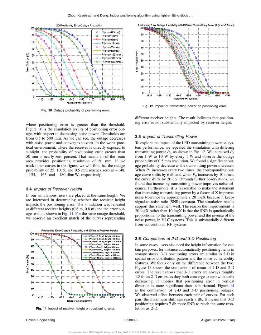
where positioning error is greater than the threshold.Figure 10 is the simulation results of positioning error out-age, with respect to decreasing noise power. Thresholds arefrom 0.5 to 500 mm. As we can see, the outage decreaseswith noise power and converges to zero. In the worst prac-tical environment, where the receiver is directly exposed tosunlight, the probability of positioning error greater than50 mm is nearly zero percent. That means all of the roomarea provides positioning resolution of 50 mm. If wetrack other curves in the figure, we will find that the outageprobability of 25, 10, 5, and 0.5 mm reaches zero at −148,−155, −163, and −180 dbmW, respectively.
3.4 Impact of Receiver Height
In our simulations, users are placed at the same height. Weare interested in determining whether the receiver heightimpacts the positioning error. The simulation was repeatedat different receiver heights (0.6 m, 0.8 m) and the error out-age result is shown in Fig. 11. For the same outage threshold,we observe an excellent match of the curves representing
different receiver heights. The result indicates that position-ing error is not substantially impacted by receiver height.
3.5 Impact of Transmitting Power
To explore the impact of the LED transmitting power on sys-tem performance, we repeated the simulation with differingtransmitting power P0, as shown in Fig. 12. We increased P0
from 1 W to 10 W by every 1 W and observe the outageprobability of 0.5 mm resolution. We found a significant out-age probability decrease as the transmitting power increases.When P0 increases every two times, the corresponding out-age curve shifts by 6 db and when P0 increases by 10 times,the curve shifts by 20 db. Through further observations, wefound that increasing transmitting power improves noise tol-erance. Furthermore, it is reasonable to make the statementthat increasing transmitting power by a factor of X improvesnoise tolerance by approximately 20 logX because it keepssignal-to-noise ratio (SNR) constant. The simulation resultssupport this statement well. The reason the improvement is20 logX rather than 10 logX is that the SNR is quadraticallyproportional to the transmitting power and the inverse of thenoise power, in VLC systems. This is substantially differentfrom conventional RF systems.
3.6 Comparison of 2-D and 3-D Positioning
In some cases, users also need the height information for cer-tain purposes, for instance automatically positioning items instorage stacks. 3-D positioning errors are similar to 2-D inspatial error distribution pattern and the noise vulnerabilityfeatures. We focus only on the difference between the two.Figure 13 shows the comparison of mean of 2-D and 3-Derrors. The result shows that 3-D errors are always roughly1.8 times 2-D errors, as they both converge to zero with noisedecreasing. It implies that positioning error in verticaldirection is more significant than in horizontal. Figure 14is the comparison of 2-D and 3-D positioning outages.We observed offset between each pair of curves. For eachpair, the maximum shift can reach 7 db. It means that 3-Dpositioning requires 7 db more SNR to reach the same reso-lution as 2-D.
Fig. 10 Outage probability of positioning error.
Fig. 11 Impact of receiver height on positioning error.
Fig. 12 Impact of transmitting power on positioning error.
Optical Engineering 085009-5 August 2012/Vol. 51(8)
Zhou, Kavehrad, and Deng: Indoor positioning algorithm using light-emitting diode : : :
Downloaded from SPIE Digital Library on 21 Aug 2012 to 130.203.199.134. Terms of Use: http://spiedl.org/terms

4 ConclusionsThe paper proposes a novel visible light indoor positioningtechnique, by solving the Lambertian transmission equationgroup. According to our results, this method reducespositioning error to less than 0.5 mm, as the state-of-the-art microwave indoor positioning can only reduce theerror to tens of centimeters. Our research also shows thatthe performance of this approach is not impacted by receiverheight. Moreover, this method provides not only conven-tional 2-D position information, but also 3-D information.There is 80% increase in the mean of positioning error,and 7 dB less noise tolerance, when 3-D is applied insteadof 2-D positioning.
References
1. M. Kavehrad and J. Fadlullah, “Wideband optical propagation measure-ment system for characterization of indoor optical wireless channels,”Proc. SPIE 7620, 76200E (2010).
2. Y. U. Lee et al., “Hybrid positioning with lighting LEDs and Zigbeemultihop wireless networks,” Proc. SPIE 8282, 82820L (2012).
3. S. Tilch and R. Mautz, “Current investigations at the ETH Zurich inoptical indoor positioning,” in 7th workshop on WPNC, Dresden,pp. 174–178 (2010).
4. M. Cypriani et al., “Wi-fi-based indoor positioning basic techniques,hybrid algorithms and open software platform,” in Int. Conf. on IPIN,Zurich, pp. 1–10 (2010).
5. K. Tan and C. Law, “GPS and UWB integration for indoor positioning,”in Int. Conf. on ICSP, Singapore, pp. 1–5 (2007).
6. S. Jeon and J. Park, “A RFID reader configuration with an enhancedrecognition property for indoor positioning,” in Fifth Int. Joint Conf.on INC, IMS, and IDC. NCM’09, Seoul, pp. 166–169 (2009).
7. J. Xiao et al., “Comparison and analysis of indoor wireless positioningtechniques,” in Int. Conf. on CSSS, Nanjing, pp. 293–296 (2011).
8. J. Barry et al., “Simulation of multipath impulse response for indoorwireless optical channels,” IEEE J. Sel. Area Commun. 11(3),367–379 (1993).
9. Y. Alqudah and M. Kavehrad, “MIMO characterization of indoor wire-less optical link using a diffuse-transmission configuration,” IEEETrans. Commun. 51(9), 1554–1560 (2003).
10. C. Chow et al., “Improved modulation speed of LED visible light com-munication system integrated to main electricity network,” Electron.Lett. 47(15), 867–868 (2011).
11. M. Wolf and D. Kress, “Short-range wireless infrared transmission: thelink budget compared to RF,” IEEE Wireless Commun. 10(2), 8–14(2003).
Zhou Zhou is a PhD candidate in the depart-ment of electrical engineering at the Pennsyl-vania State University, supervised byMohsen Kavehrad. He is a researcher atthe Center for Information and Communica-tions Technology Research (CICTR). He isalso a student member of IEEE. His researchinterests include wireless and mobile net-works, visible light communications andindoor navigations.
Mohsen Kavehrad is with the PennsylvaniaState University electrical engineeringdepartment as Weiss Chair Professor anddirector of the CICTR. He has over 350 pub-lished papers, book chapters, books, and keypatents. His research interests are in theareas of wireless and optical communica-tions networked systems. He has receivedthree Bell Labs awards, the 1990 TRIO Feed-back Award for a patent on optical intercon-nect, the 2001 IEEE VTS Best Paper Award,
three IEEE LEOS Best Paper Awards and a Canada NSERC PhDthesis award with his graduate students for contributions to wirelessand optical networks.
Peng Deng is working toward the PhDdegree in Wuhan National Laboratory forOptoelectronics, department of optoelectro-nic science and engineering, Huazhong Uni-versity of Science & Technology, Wuhan,China. Currently, he is a visiting PhD studentwith the CICTR, electrical engineeringdepartment, Pennsylvania State University.His research interests are optical systemdesign, free space optical communicationsthrough atmospheric turbulence, and com-
pensation techniques.
Fig. 13 Comparison of mean of 2-D and 3-D positioning error.
Fig. 14 Comparison of outage probability of 2-D and 3-D positioningerror.
Optical Engineering 085009-6 August 2012/Vol. 51(8)
Zhou, Kavehrad, and Deng: Indoor positioning algorithm using light-emitting diode : : :
Downloaded from SPIE Digital Library on 21 Aug 2012 to 130.203.199.134. Terms of Use: http://spiedl.org/terms
Related Documents