1468 IEEE TRANSACTIONS ON ANTENNAS AND PROPAGATION, VOL. 58, NO. 5, MAY 2010 Switchable Quad-Band Antennas for Cognitive Radio Base Station Applications Terence Wu, Student Member, IEEE, Rong Lin Li, Senior Member, IEEE, Soon Young Eom, Member, IEEE, Seong Sik Myoung, Student Member, IEEE, Kyutae Lim, Member, IEEE, Joy Laskar, Fellow, IEEE, Soon Ik Jeon, and Manos M. Tentzeris, Senior Member, IEEE Abstract—A novel antenna configuration for quad-band oper- ation is presented. The quad-band antenna has a directional ra- diation pattern in four frequency bands, i.e., B1 (800–900 MHz), B2 (1.7–2.5 GHz), B3 (3.3–3.6 GHz), and B4 (5.1–5.9 GHz), cov- ering all spectrums for existing wireless applications, such as GSM, PCS, WCDMA, WiFi, and WiMax. The operating frequency of the quad-band antenna can be adjusted by the use of a MEMS switch, making it suitable for cognitive radio applications. First a switch- able quad-band antenna element is introduced. Then a two-ele- ment antenna array is developed to increase the antenna gain for base station applications featuring a gain value of about 9–11 dBi over all four frequency bands. Index Terms—Base station antenna, cognitive radio, quad-band antenna, switchable antenna. I. INTRODUCTION W ITH the increasing demand for wireless connectivity, the radio frequency spectrum is getting more and more crowded with applications satisfying communication needs for public, private, and government sectors. The spectrum conges- tion increases the cost of spectrum licensing, which ultimately leads to a higher cost per bit for each user. Cognitive radio aims to reduce spectrum congestion by sensing unused bandwidth in the existing communication standards and opportunistically maximizes the spectrum utilization for the end user [1]. In the public communication sector, several bands are allocated to ex- isting standards, such as GSM, PCS, WCDMA, WiFi, and the recently adopted WiMax worldwide. It is advantageous to pro- vide cognitive radio services that maximize the data delivery Manuscript received April 20, 2009; revised September 22, 2009; accepted November 16, 2009. Date of publication March 01, 2010; date of current version May 05, 2010. This work was supported by the IT R&D program of MKE/IITA [2007-F-041-01, Intelligent Antenna Technology Development]. T. Wu, K. Lim, J. Laskar, and M. M. Tentzeris are with the School of Electrical and Computer Engineering, Georgia Institute of Technology, At- lanta, GA 30308 USA (e-mail: [email protected]; [email protected]; [email protected]; [email protected]). R. L. Li is with the School of Electronic and Information Engineering, South China University of Technology, Guangzhou 510641, China and also with the School of Electrical and Computer Engineering, Georgia Institute of Technology, Atlanta, GA 30308 USA. (e-mail: [email protected]). S. S. Myoung was with Dept. of Electrical and Electronic Engineering, Yonsei University, Seoul 120-749, Korea and also with the School of Electrical and Computer Engineering, Georgia Institute of Technology, Atlanta, GA 30308 USA. He is now with Samsung Electronics Inc., Seoul 137-857, South Korea (e-mail: [email protected]). S. Y. Eom and S. I. Jeon are with the Electronics and Telecommunications Research Institute, Yuseong-gu, Daejeon, 305-700, Korea. Color versions of one or more of the figures in this paper are available online at http://ieeexplore.ieee.org. Digital Object Identifier 10.1109/TAP.2010.2044472 across those existing communication standards utilizing a single base station antenna system. To support the comprehensive and intelligent communica- tion offered by cognitive radio architecture, a new paradigm of RF front-end is needed [2]. Due to wide spectral bandwidth utilization, reducing interference between the radios is critical in improving their signal to noise ratio and the overall spectrum usage. Thus RF front-ends need to limit its instantaneous dynamic range to avoid non-linear distortion in the desired channel [3]. Several authors have proposed antenna structures that would reduce antennas’ dynamic range by the use of switches [4]–[11]. Switchable antennas can be realized using electronic switches, such as varactor diodes or MEMS switches. Three types of switchable/reconfigurable antennas have been implemented in the literature: polarization [4], [5], spectral [5]–[9], and spatial [8]–[11]. For base station antennas, spatial and spectral sensing are the two areas of interest. In traditional base stations, several antenna techniques have been established to enhance system capacity. 1) The antenna is positioned with its E plane perpendicular to earth surface to uti- lize ground reflections for increasing signal range. 2) To elim- inate co-channel interference between adjacent towers and in- crease spectrum reuse, spatial sectoring is implemented in the antenna’s H plane. Horizontal beam width typically varies be- tween 60 , 90 , 120 , 180 , to 360 depending on the number of sectors deployed [12]. 3) To further reduce the co-channel inter- ference between adjacent towers and enhance signal strength to- wards the mobile device, a narrow vertical beam width ranging from 7 to 20 with beam tilting is desired. Thus an antenna array needs to be extended vertically along its E plane. Such array implementation is difficult to achieve in frequency agile antenna designs since the electrical element spacing for each frequency band must be almost the same in wavelengths to avoid grating lobes. Grating lobe and side lobe formation results in large signal variation in the service area, and should be reduced unless the system can spatially reconfigure the null position to its advantage. Due to grating lobe considerations, most existing directional multi-band antennas cannot be easily extended to array configurations along their E plane, because these antennas share the same radiating element at different frequency bands [5], [9], [13]–[15]. In this paper, a switchable multi-band two radiator element is introduced and optimized to offer a sectored radiation pattern in four frequency bands: 800–900 MHz (B1), 1.7–2.5 GHz (B2), 3.3–3.6 GHz (B3), and 5.1–5.9 GHz (B4), used for GSM, PCS, WCDMA, WiFi and WiMAX systems. This quad-band two radiator architecture is “arrayable” because the radiating 0018-926X/$26.00 © 2010 IEEE

Welcome message from author
This document is posted to help you gain knowledge. Please leave a comment to let me know what you think about it! Share it to your friends and learn new things together.
Transcript

1468 IEEE TRANSACTIONS ON ANTENNAS AND PROPAGATION, VOL. 58, NO. 5, MAY 2010
Switchable Quad-Band Antennas for Cognitive RadioBase Station Applications
Terence Wu, Student Member, IEEE, Rong Lin Li, Senior Member, IEEE, Soon Young Eom, Member, IEEE,Seong Sik Myoung, Student Member, IEEE, Kyutae Lim, Member, IEEE, Joy Laskar, Fellow, IEEE,
Soon Ik Jeon, and Manos M. Tentzeris, Senior Member, IEEE
Abstract—A novel antenna configuration for quad-band oper-ation is presented. The quad-band antenna has a directional ra-diation pattern in four frequency bands, i.e., B1 (800–900 MHz),B2 (1.7–2.5 GHz), B3 (3.3–3.6 GHz), and B4 (5.1–5.9 GHz), cov-ering all spectrums for existing wireless applications, such as GSM,PCS, WCDMA, WiFi, and WiMax. The operating frequency of thequad-band antenna can be adjusted by the use of a MEMS switch,making it suitable for cognitive radio applications. First a switch-able quad-band antenna element is introduced. Then a two-ele-ment antenna array is developed to increase the antenna gain forbase station applications featuring a gain value of about 9–11 dBiover all four frequency bands.
Index Terms—Base station antenna, cognitive radio, quad-bandantenna, switchable antenna.
I. INTRODUCTION
W ITH the increasing demand for wireless connectivity,the radio frequency spectrum is getting more and more
crowded with applications satisfying communication needs forpublic, private, and government sectors. The spectrum conges-tion increases the cost of spectrum licensing, which ultimatelyleads to a higher cost per bit for each user. Cognitive radio aimsto reduce spectrum congestion by sensing unused bandwidthin the existing communication standards and opportunisticallymaximizes the spectrum utilization for the end user [1]. In thepublic communication sector, several bands are allocated to ex-isting standards, such as GSM, PCS, WCDMA, WiFi, and therecently adopted WiMax worldwide. It is advantageous to pro-vide cognitive radio services that maximize the data delivery
Manuscript received April 20, 2009; revised September 22, 2009; acceptedNovember 16, 2009. Date of publication March 01, 2010; date of current versionMay 05, 2010. This work was supported by the IT R&D program of MKE/IITA[2007-F-041-01, Intelligent Antenna Technology Development].
T. Wu, K. Lim, J. Laskar, and M. M. Tentzeris are with the School ofElectrical and Computer Engineering, Georgia Institute of Technology, At-lanta, GA 30308 USA (e-mail: [email protected]; [email protected];[email protected]; [email protected]).
R. L. Li is with the School of Electronic and Information Engineering,South China University of Technology, Guangzhou 510641, China and alsowith the School of Electrical and Computer Engineering, Georgia Institute ofTechnology, Atlanta, GA 30308 USA. (e-mail: [email protected]).
S. S. Myoung was with Dept. of Electrical and Electronic Engineering, YonseiUniversity, Seoul 120-749, Korea and also with the School of Electrical andComputer Engineering, Georgia Institute of Technology, Atlanta, GA 30308USA. He is now with Samsung Electronics Inc., Seoul 137-857, South Korea(e-mail: [email protected]).
S. Y. Eom and S. I. Jeon are with the Electronics and TelecommunicationsResearch Institute, Yuseong-gu, Daejeon, 305-700, Korea.
Color versions of one or more of the figures in this paper are available onlineat http://ieeexplore.ieee.org.
Digital Object Identifier 10.1109/TAP.2010.2044472
across those existing communication standards utilizing a singlebase station antenna system.
To support the comprehensive and intelligent communica-tion offered by cognitive radio architecture, a new paradigmof RF front-end is needed [2]. Due to wide spectral bandwidthutilization, reducing interference between the radios is criticalin improving their signal to noise ratio and the overall spectrumusage. Thus RF front-ends need to limit its instantaneousdynamic range to avoid non-linear distortion in the desiredchannel [3]. Several authors have proposed antenna structuresthat would reduce antennas’ dynamic range by the use ofswitches [4]–[11]. Switchable antennas can be realized usingelectronic switches, such as varactor diodes or MEMS switches.Three types of switchable/reconfigurable antennas have beenimplemented in the literature: polarization [4], [5], spectral[5]–[9], and spatial [8]–[11]. For base station antennas, spatialand spectral sensing are the two areas of interest.
In traditional base stations, several antenna techniques havebeen established to enhance system capacity. 1) The antenna ispositioned with its E plane perpendicular to earth surface to uti-lize ground reflections for increasing signal range. 2) To elim-inate co-channel interference between adjacent towers and in-crease spectrum reuse, spatial sectoring is implemented in theantenna’s H plane. Horizontal beam width typically varies be-tween 60 , 90 , 120 , 180 , to 360 depending on the number ofsectors deployed [12]. 3) To further reduce the co-channel inter-ference between adjacent towers and enhance signal strength to-wards the mobile device, a narrow vertical beam width rangingfrom 7 to 20 with beam tilting is desired. Thus an antennaarray needs to be extended vertically along its E plane. Sucharray implementation is difficult to achieve in frequency agileantenna designs since the electrical element spacing for eachfrequency band must be almost the same in wavelengths to avoidgrating lobes. Grating lobe and side lobe formation results inlarge signal variation in the service area, and should be reducedunless the system can spatially reconfigure the null position toits advantage. Due to grating lobe considerations, most existingdirectional multi-band antennas cannot be easily extended toarray configurations along their E plane, because these antennasshare the same radiating element at different frequency bands[5], [9], [13]–[15].
In this paper, a switchable multi-band two radiator element isintroduced and optimized to offer a sectored radiation patternin four frequency bands: 800–900 MHz (B1), 1.7–2.5 GHz(B2), 3.3–3.6 GHz (B3), and 5.1–5.9 GHz (B4), used for GSM,PCS, WCDMA, WiFi and WiMAX systems. This quad-bandtwo radiator architecture is “arrayable” because the radiating
0018-926X/$26.00 © 2010 IEEE

WU et al.: SWITCHABLE QUAD-BAND ANTENNAS FOR COGNITIVE RADIO BASE STATION APPLICATIONS 1469
Fig. 1. Configuration of a quad-band antenna element.
elements for each frequency bands can be readjusted along itsE plane. Its two element array will be presented to demonstratethe possibility of beam width narrowing and beam tilting alongits E plane, as desired by base stations. Furthermore, thisquad-band antenna geometry has a compact form factor andhigh scalability to incorporate additional frequency bands inthe future. Design and measurement results for the quad-bandantenna element are first introduced, followed by a descriptionof the system level requirement and the design process of thequad-band array.
II. QUAD-BAND TWO RADIATOR ELEMENT
The configuration of the proposed switchable quad-band an-tenna element is shown in Fig. 1. For B1, B2, and B3, there isa pair of symmetrically positioned dipole arms in the y direc-tion. The separation between the dipole arms is approximately
with being the free-space wavelength at the center fre-quency for each frequency band. Only a single dipole is used forB4 because it is located exactly in the center of symmetry. Thedipole arm selected was based on “the printed broadband dipoleantenna with integrated balun” documented in [16]–[20]. It pro-vides a simple broadband dipole structure with the capability toeasily tune the impedance matching. With this structure, the ra-diation pattern of the quad-band antenna can be easily controlledby the relative position of the dipole arms and the dipole length,while the impedance matching is individually controlled by thebalun matching network.
The quad-band antenna has four ports as indicated in Fig. 1,and is designed to be controlled by a TeraVicta SP4T MEMSswitch. A schematic of the MEMS switch system is shown inFig. 2, which includes a front-end amplifier (RFA), a digital con-troller, and an SP4T MEMS switch. The MEMS switch imple-mentation is an active area of research because it offers lowerloss, high isolation, and high linearity desired by the in RF front
Fig. 2. A schematic of a switch system for the quad-band antenna element.
Fig. 3. A prototype of the quad-band antenna element.
end [21]. In this paper, the switch performance will not be cov-ered and an ideal switch is assumed to be connected to the portsof the quad-band antenna element.
The antenna was designed using Microstripes 7.5, a TLMbased commercial solver, with a Taconic RF35 substrate of
and . The dipole arms weredesigned on 30 mils (0.762 mm) substrate to provide bettermechanical stability for standing perpendicular to the ground,while the base board was designed on 20 mils (0.508 mm) toallow narrower feeding lines on board. A feeding network wasdesigned for each frequency band, and 35 quarter wavelengthtransformers were used to split the input power into two 50antenna loads. To mimic the behavior of the MEMS switch,non-active ports were left as open circuits in both simulationsand measurements. A prototype of the quad-band antenna el-ement is pictured in Fig. 3. A 400 mm 400 mm groundplane was used to support the quad-band antenna. The opti-mized dipole arms dimensions and dipole spacing are listed inTable I. The optimization was done in a three stage process:1) radiation pattern and matching of individual dipole arms aresimulated in the four frequencies of interest, 2) the H-planeradiation pattern is optimized by adjusting relative spacing ofthe dipole, and 3) the balun transition of each dipole arm isreadjusted to tune the impedance after including the affects ofradiator spacing and feeding network.
1470 IEEE TRANSACTIONS ON ANTENNAS AND PROPAGATION, VOL. 58, NO. 5, MAY 2010
TABLE IDIMENSIONS OF THE QUAD-BAND ANTENNA ELEMENT (MM)
Fig. 4. H-plane Radiation affected by (a) adjacent lower frequency dipoles,effect of� on B4 at 5.5 GHz, (b) grating lobe, effect of� on B2 at 2.4 GHz.
To design the individual dipole arm, of was chosenfor the printed dipole length elevated above the groundplane . The dipole width , which is half of forimpedance matching, needs to be at least 3 times greater thanwm, the feed line width. This allows microstrip mode of thefeed line, and constant impedance between the ground to the ra-diating dipole ends. By selecting , and mainly adjusting
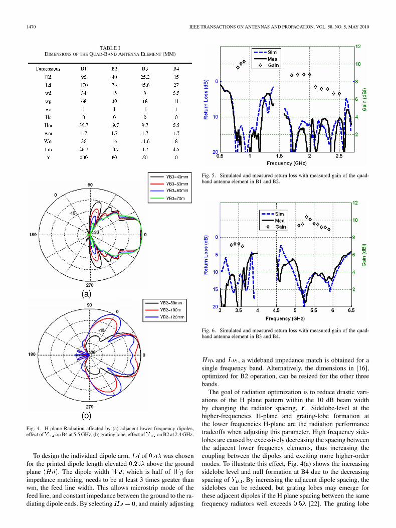
Fig. 5. Simulated and measured return loss with measured gain of the quad-band antenna element in B1 and B2.
Fig. 6. Simulated and measured return loss with measured gain of the quad-band antenna element in B3 and B4.
and , a wideband impedance match is obtained for asingle frequency band. Alternatively, the dimensions in [16],optimized for B2 operation, can be resized for the other threebands.
The goal of radiation optimization is to reduce drastic vari-ations of the H plane pattern within the 10 dB beam widthby changing the radiator spacing, . Sidelobe-level at thehigher-frequencies H-plane and grating-lobe formation atthe lower frequencies H-plane are the radiation performancetradeoffs when adjusting this parameter. High frequency side-lobes are caused by excessively decreasing the spacing betweenthe adjacent lower frequency elements, thus increasing thecoupling between the dipoles and exciting more higher-ordermodes. To illustrate this effect, Fig. 4(a) shows the increasingsidelobe level and null formation at B4 due to the decreasingspacing of . By increasing the adjacent dipole spacing, thesidelobes can be reduced, but grating lobes may emerge forthese adjacent dipoles if the H plane spacing between the samefrequency radiators well exceeds [22]. The grating lobe
WU et al.: SWITCHABLE QUAD-BAND ANTENNAS FOR COGNITIVE RADIO BASE STATION APPLICATIONS 1471
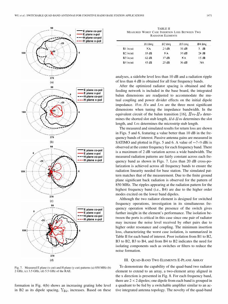
Fig. 7. Measured E plane (x-cut) and H plane (y-cut) patterns (a) 850 MHz (b)2 GHz, (c) 3.5 GHz, (d) 5.5 GHz of the RAE.
formation in Fig. 4(b) shows an increasing grating lobe levelin B2 as its dipole spacing, , increases. Based on these
TABLE IIMEASURED WORST CASE INSERTION LOSS BETWEEN TWO
RADIATOR ELEMENTS
analyses, a sidelobe level less than 10 dB and a radiation rippleof less than 4 dB is obtained for all four frequency bands.
After the optimized radiator spacing is obtained and thefeeding network is included in the base board, the integratedbalun dimensions are readjusted to accommodate the mu-tual coupling and power divider effects on the initial dipoleimpedance. and are the three most significantdimensions when tuning the impedance bandwidth. In theequivalent circuit of the balun transition [16], - deter-mines the shorted slot stub length, - determines the slotlength, and determines the microstrip stub length.
The measured and simulated results for return loss are shownin Figs. 5 and 6, featuring a value better than 10 dB in the fre-quency bands of interest. Passive antenna gains are measured inSATIMO and plotted in Figs. 5 and 6. A value of – dBi isobserved at the center frequency for each frequency band. Thereis a maximum of 2 dB variation across a wide bandwidth. Themeasured radiation patterns are fairly constant across each fre-quency band as shown in Figs. 7. Less than 20 dB cross-po-larization is achieved across all frequency bands to ensure theradiation linearity needed for base station. The simulated pat-tern matches that of the measurement. Due to the finite groundplane significant back radiation is observed for the pattern of850 MHz. The ripples appearing at the radiation pattern for thehighest frequency band (i.e., B4) are due to the higher ordermodes excited on the lower band dipoles.
Although the two radiator element is designed for switchedfrequency operations, investigation in its simultaneous fre-quency operation without the presence of the switch givesfurther insight in the element’s performance. The isolation be-tween the ports is critical in this case since one pair of radiatormay increase the noise level received by other pairs due tohigher order resonance and coupling. The minimum insertionloss, characterizing the worst case isolation, is summarized inTable II for each band of interest. Poor isolation from B1 to B2,B3 to B2, B3 to B4, and from B4 to B2 indicates the need forisolating components such as switches or filters to reduce thenoise formation.
III. QUAD-BAND TWO ELEMENTS E-PLANE ARRAY
To demonstrate the capability of the quad-band two radiatorelement to extend to an array, a two-element array aligned inthe x direction is presented in Fig. 8. For each frequency band,there are 2 2 dipoles; one dipole from each band is grouped ina quadrant to be fed by a switchable amplifier similar to an ac-tive integrated antenna topology. The novelty of the quad-band
1472 IEEE TRANSACTIONS ON ANTENNAS AND PROPAGATION, VOL. 58, NO. 5, MAY 2010
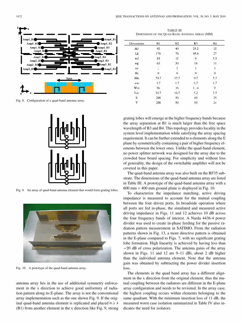
Fig. 8. Configuration of a quad-band antenna array.
Fig. 9. An array of quad-band antenna element that would form grating lobes.
Fig. 10. A prototype of the quad-band antenna array.
antenna array lies in the use of additional symmetry enforce-ment in the x direction to achieve good uniformity of radia-tion pattern along its E-plane. The array is not the conventionalarray implementation such as the one shown Fig. 9. If the orig-inal quad-band antenna element is replicated and placed(B1) from another element in the x direction like Fig. 9, strong
TABLE IIIDIMENSIONS OF THE QUAD-BAND ANTENNA ARRAY (MM)
grating lobes will emerge at the higher frequency bands becausethe array separation at B1 is much larger than the free spacewavelength of B3 and B4. This topology provides locality in thesystem level implementation while satisfying the array spacingrequirement. It can be further extended to n elements along the Eplane by symmetrically containing a pair of higher frequency el-ements between the lower ones. Unlike the quad-band element,no power splitter network was designed for the array due to thecrowded base board spacing. For simplicity and without lossof generality, the design of the switchable amplifier will not becovered in this paper.
The quad-band antenna array was also built on the RF35 sub-strate. The dimensions of the quad-band antenna array are listedin Table III. A prototype of the quad-band antenna array with a600 mm 400 mm ground plane is displayed in Fig. 10.
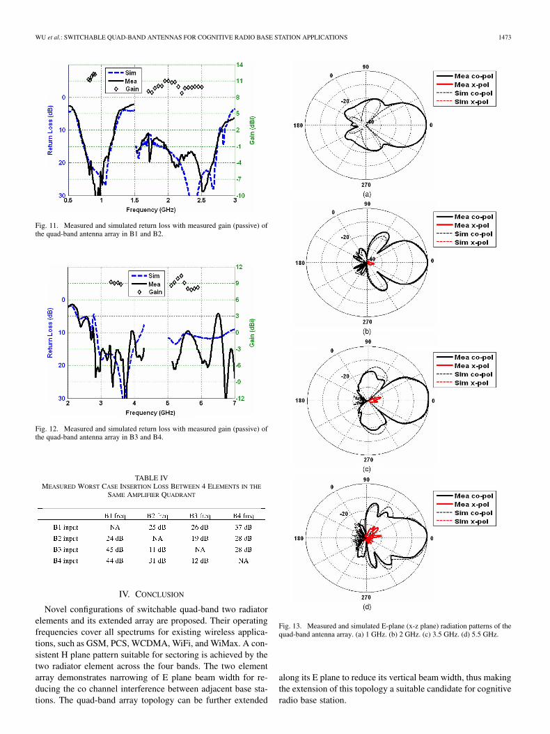
To characterize the impedance matching, active drivingimpedance is measured to account for the mutual couplingbetween the four driven ports. In broadside operation whereall ports are fed in-phase, the simulated and measured activedriving impedance in Figs. 11 and 12 achieves 10 dB acrossthe four frequency bands of interest. A Narda 4436-4 powerdivider was used to create in-phase feeding for the passive ra-diation pattern measurement in SATIMO. From the radiationpatterns shown in Fig. 13, a more directive pattern is obtainedin the E-plane compared to Figs. 7, with no significant gratinglobe formation. High linearity is achieved by having less than
dB of cross polarization. The antenna gains of the arrayshown in Figs. 11 and 12 are 9–11 dBi, about 2 dB higherthan the individual antenna element. Note that the antennagain was obtained by subtracting the power divider insertionloss.
The elements in the quad band array has a different align-ment in the x direction from the original element, thus the mu-tual coupling between the radiators are different in the E-planearray configuration and needs to be revisited. In the array case,the highest coupling occurs within elements belonging to thesame quadrant. With the minimum insertion loss of 11 dB, themeasured worst case isolation summarized in Table IV also in-dicates the need for isolators.
WU et al.: SWITCHABLE QUAD-BAND ANTENNAS FOR COGNITIVE RADIO BASE STATION APPLICATIONS 1473
Fig. 11. Measured and simulated return loss with measured gain (passive) ofthe quad-band antenna array in B1 and B2.
Fig. 12. Measured and simulated return loss with measured gain (passive) ofthe quad-band antenna array in B3 and B4.
TABLE IVMEASURED WORST CASE INSERTION LOSS BETWEEN 4 ELEMENTS IN THE
SAME AMPLIFIER QUADRANT
IV. CONCLUSION
Novel configurations of switchable quad-band two radiatorelements and its extended array are proposed. Their operatingfrequencies cover all spectrums for existing wireless applica-tions, such as GSM, PCS, WCDMA, WiFi, and WiMax. A con-sistent H plane pattern suitable for sectoring is achieved by thetwo radiator element across the four bands. The two elementarray demonstrates narrowing of E plane beam width for re-ducing the co channel interference between adjacent base sta-tions. The quad-band array topology can be further extended
Fig. 13. Measured and simulated E-plane (x-z plane) radiation patterns of thequad-band antenna array. (a) 1 GHz. (b) 2 GHz. (c) 3.5 GHz. (d) 5.5 GHz.
along its E plane to reduce its vertical beam width, thus makingthe extension of this topology a suitable candidate for cognitiveradio base station.
1474 IEEE TRANSACTIONS ON ANTENNAS AND PROPAGATION, VOL. 58, NO. 5, MAY 2010
ACKNOWLEDGMENT
The authors would like to thank K. Rutkowski of SATIMOAtlanta for the pattern measurements, Taconic Advance Dielec-tric Division for providing the substrate samples and CST Mi-crostripes for its simulation capabilities. The authors also wishto acknowledge the support of the Georgia Electronic DesignCenter (GEDC).
REFERENCES
[1] J. Mitola, III, “Cognitive radio for flexible mobile multimedia commu-nication,” in Proc. IEEE Int. Workshop on Mobile Multimedia Commu-nications (MoMuC) 1999, Nov. 1999, pp. 3–10.
[2] K. Lim and J. Laskar, “Emerging opportunities of RF IC/system forfuture cognitive radio wireless communications,” in Proc. IEEE Radioand Wireless Symp., Jan. 2008, pp. 703–706.
[3] P. S. Hall, P. Gardner, J. Kelly, E. Ebrahimi, M. R. Hamid, and F.Ghanem, “Antenna challenges in cognitive radio,” presented at the Int.Symp. on Antennas and Propagation, Oct. 2008.
[4] M. K. Fries, M. Grani, and R. Vahldieck, “A reconfigurable slot antennawith switchable polarization,” IEEE Microw. Wireless Compon. Lett.,vol. 13, no. 11, pp. 490–492, Nov. 2003.
[5] B. A. Cetiner, H. Jafarkhani, J.-Y. Qian, H. J. Yoo, A. Grau, and F. DeFlaviis, “Multifunctional reconfigurable MEMS integrated antennasfor adaptive MIMO systems,” IEEE Commun. Mag., vol. 42, no. 12,pp. 62–70, Dec. 2004.
[6] A. E. Fathy, A. Rosen, H. S. Owen, F. McGinty, D. J. McGee, G. C.Taylor, R. Amantea, P. K. Swain, S. M. Perlow, and M. ElSherbiny,“Silicon-based reconfigurable antennas-concepts, analysis, implemen-tation, and feasibility,” IEEE Trans. Microw. Theory Tech., vol. 51, no.6, pp. 1650–1661, Jun. 2003.
[7] C. Zhang, S. Yang, H. K. Pan, A. E. Fathy, S. El-Ghazaly, and V. Nair,“Reconfigurable antenna for simultaneous multi-service wireless ap-plications,” in Proc. IEEE Radio and Wireless Symp., Jan. 9–11, 2007,pp. 543–546.
[8] L. N. Pringle, P. H. Harms, S. P. Blalock, G. N. Kiesel, E. J. Kuster, P.G. Friederich, R. J. Prado, J. M. Morris, and G. S. Smith, “A reconfig-urable aperture antenna based on switched links between electricallysmall metallic patches,” IEEE Trans. Antennas Propag., vol. 52, no. 6,pp. 1434–1445, Jun. 2004.
[9] A. Mirkimali and P. S. Hall, “Log periodic printed dipole array forwideband frequency reconfiguration,” presented at the IET Seminar onWideband/Multiband Antennas and Arrays for Civil or Defence Appli-cations, London, Mar. 13, 2008.
[10] S. Zhang, G. H. Huff, J. Feng, and J. T. Bernhard, “A pattern reconfig-urable microstrip parasitic array,” IEEE Trans. Antennas Propag., vol.52, no. 10, pp. 2773–2776, Oct. 2004.
[11] C. Alakija and S. P. Stapleton, “A mobile base station phased arrayantenna,” presented at the Int. Conf. on Selected Topics in WirelessCommunications, Vancouver, Jun. 1992.
[12] C. A. Balanis, Antenna Theory: Analysis and Design, 3rded. Hoboken, NJ: Wiley, 2005, pp. 946–951.
[13] S. K. Palit and A. Hamadi, “Design and development of wideband anddual-band microstrip antennas,” IEE Proc.-Microw. Antennas Propag.,vol. 146, no. 1, pp. 35–39, Feb. 1999.
[14] F. Tefiku and C. A. Grimes, “Design of broad-band and dual-band an-tennas comprised of series-fed printed-strip dipole pairs,” IEEE Trans.Antennas Propag., vol. 48, no. 6, pp. 895–900, Jun. 2000.
[15] P. Li, K. M. Kuk, and K. L. Lau, “A dual-feed dual-band L-probepatch antenna,” IIEEE Trans. Antennas Propag., vol. 53, no. 7, pp.2321–2323, Jul. 2005.
[16] R. L. Li, B. Pan, T. Wu, K. Lim, J. Laskar, and M. M. Tentzeris, “Equiv-alent-circuit analysis and design of a broadband printed dipole withadjusted integrated balun and a printed array for base station applica-tions,” IEEE Trans. Antennas Propag., vol. 57, no. 7, Jul. 2009.
[17] C. Ha, Y. Qian, and T. Itoh, “A modified Quasi-Yagi planar antennawith wideband characteristics in C-band,” in Proc. IEEE Antennas andPropagation Society Int. Symp., Jul. 8–13, 2001, vol. 3, pp. 154–157.
[18] H. K. Kan, R. B. Waterhouse, A. M. Abbosh, M. E. Bialkowski, and K.L. Chung, “A simple broadband planar Quasi-Yagi antenna,” presentedat the IEEE TENCON, Nov. 14–17, 2006.
[19] B. Edward and D. Rees, “A broadband printed dipole with integratedbalun,” Microw. J., pp. 339–344, May 1987.
[20] P. Lindberg, E. Ojefors, Z. Barna, A. Thornell-Pers, and A. Rydberg,“Dual wideband printed dipole antenna with integrated balun,” IET Mi-crow. Antennas Propag., vol. 1, no. 3, pp. 707–711, Jun. 2007.
[21] E. R. Brown, “RF-MEMS switches for reconfigurable integratedcircuits,” IEEE Trans. Microw. Theory Tech., vol. 46, no. 11, pp.1868–1880, Nov. 1998.
[22] T. A. Milligan, Modern Antenna Design, 2nd ed. New York: Mc-Graw-Hill, 2005, pp. 106–107.
Terence Wu (S’05) received the B.S. degree inelectrical engineering from Georgia Institute ofTechnology in 2005. He is currently working towardthe Ph.D. degree in electrical engineering under Dr.Tentzeris.
His research interests include antenna miniatur-ization for portable electronics, multiband arrayintegration, antennas integration/packaging forwireless sensor nodes and RFID technology.
Mr. Wu was the recipient of the 2009 IEEE APSSymposium Student Paper Honorable Mention
Award.
Rong Lin Li (M’02–SM’03) received the B.S. degreein electrical engineering from Xi’an Jiaotong Univer-sity, China, in 1983, and the M.S. and Ph.D. degreesin electrical engineering from Chongqing University,in 1990 and 1994, respectively.
From 1983 to 1987, he worked as an AssistantElectrical Engineer in Yunnan Electric PowerResearch Institute. From 1994 to 1996, he was aPostdoctoral Research Fellow in Zhejiang Univer-sity, China. In 1997, he visited Hosei University,Japan, as an HIF (Hosei International Fund) Re-
search Fellow. In 1998, he became a Professor in Zhejiang University. In 1999,he visited the University of Utah, as a Research Associate. In 2000, he workedas a Research Fellow at the Queen’s University of Belfast, UK. Since 2001, hehas been a Research Scientist at Georgia Tech. He is now an Endowed Professorin the South China University of Technology and in part with the Georgia Tech.He has published more than 100 papers in refereed Journals and ConferenceProceedings, and three book chapters. His current research interests includenew design techniques for antennas in mobile and satellite communicationsystems, phased arrays and smart antennas for radar applications, wirelesssensors and RFID technology, electromagnetics and information theory.
Dr. Li is a member of the IEEE International Compumag Society. He wasa member of the Technical Program Committee for IEEE-IMS 2008 and2009 Symposia and a session chair for several IEEE-APS Symposia. He wasthe recipient of the 2009 Georgia Tech-ECE Research Spotlight Award. Hecurrently serves as an Editor of the ETRI Journal and a reviewer for a numberof international journals, including IEEE TRANSACTIONS ON ANTENNAS AND
PROPAGATION, IEEE ANTENNAS AND WIRELESS PROPAGATION LETTERS, IEEEMICROWAVE AND WIRELESS COMPONENTS LETTERS, and IET Microwave,Antennas and Propagation, Progress in Electromagnetic Research, Journal ofElectromagnetic Waves and Applications, and International Journal of WirelessPersonal Communications.
Soon-Young Eom (M’01) was born in Gangwon-do,Korea, on May 2, 1964. He received the B.S., M.S.,and the Ph.D. degrees in electronic engineering fromYonsei University, Seoul, Korea, in 1988, 1990 and2003, respectively.
Since 1990, he has worked at Electronics andTelecommunications Research Institute (ETRI),Daejeon (Korea) as a Principal Member of researchstaff. From 1991 to 1993, he participated in thejoint project with Alenia Spazio S.p.A in Italy, fordeveloping the very small aperture terminal (VSAT)
demand assignment multiple access (DAMA-SCPC) system. From 1996 to2006, he took part in developing mobile active phased array antenna systemsfor direct broadcasting satellite (DBS) reception and satellite communications.He also developed the reconfigurable antenna/RF integration technology jointlywith Georgia Technology Research Corporation, from July 2007 to July 2008.Since 2007, he has been developing an intelligent antenna system for mobilebase station. His research interests include active phased array antenna systems,microwave circuits and systems.

WU et al.: SWITCHABLE QUAD-BAND ANTENNAS FOR COGNITIVE RADIO BASE STATION APPLICATIONS 1475
Seong-Sik Myoung (S’02–M’10) was born in Taean,Korea. He received the B.S. degree in electronicsengineering from Soongsil University, Seoul, in2002 and the M.S. and Ph.D. degrees in electricaland electronic engineering from Yonsei University,Seoul, Korea, in 2004 and 2009, respectively.
He was a visiting scholar at Georgia Instituteof Technology from 2007 to 2008. He is currentlyworking on Samsung Electronics Inc., SouthKorea, as a Senior Engineer. His current researchinterests include GaAs HBT based monolithic-mi-
crowave/millimeter-wave integrated circuit design, microwave filter design,communication system design and analysis, and CMOS RF/Analog integratedcircuit design.
Dr. Myoung is a recipient of the Seoul Science Fellowship from SeoulMetropolitan government in 2005, the Bellwave Best Paper Award from KoreaElectromagnetic Engineering Society in 2005, the Best Presentation PaperAward from Korea Electromagnetic Engineering Society in 2006, and the IEEEStudent Paper Contest from the IEEE Seoul Chapter in 2006. He was selectedby Brain Korea 21 of the Korean government and received financial support forhis collaboration with the Georgia Institute of Technology in 2007. He receivedthe TMS Best Paper Award from Yonsei University in 2007 and the IEEE BestAward IEEE Seoul Chapter in 2008. He is a finalist and honorable mentionedof International Microwave Symposium of IEEE MTT Society in 2008.
Kyutae Lim (M’93) was born in Seoul, Korea, in1968. He received the B.S., M.S. and Ph.D. degreesfrom the Hanyang University, Seoul, Korea, in 1991,1993 and 1996, respectively.
From 1996 to 2000, he was with the SamsungAdvance Institute of Technology, Kiheung, Korea,as a member of technical staff. From 1998 to 1999,was with the Communication Research Lab, Tokyo,Japan, as a Research Fellow. In January 2000, hejoined Microwave Application Group in GeorgiaInstitute of Technology as a Senior Research Engi-
neer. Currently he is serving as Associate Director of Technology of GeorgiaElectronic Design Center (GEDC) at Georgia Institute of Technology. Currenttechnical projects that he is leading and co-leading are Cognitive Radio andDigital Transmitter/Receiver. His research interests include the cognitive radiobased wireless communication system and enabling technology, RF/Analogcircuit and system for wireless and high-speed system applications. He hasauthored and co-authored over 100 journal and proceeding papers and holdingfour patents. He has been invited as speakers of numerous workshops, confer-ences, regulations and standardization bodies for more than 15 times.
Dr. Lim is currently serving as the Convener of TC 48-TG 1, the wirelessstandard for the white space application, in European Computer Manufac-tures Association International. He has been serving as a Technical ProgramCommittees for numerous international conferences, including InternationalMicrowave Symposium, Cognitive Radio Oriented Wireless Network Confer-ence, and Globecom and Vehicular Technology Conference. He is a member ofthe IEEE Microwave Theory and Technique (MTT), Communication Society(ComSoc), Antennas and Propagation (AP), Signal Processing (SP), TechnicalCommittee of Cognitive Network in ComSoc.
Joy Laskar (S’84–M’85–SM’02–F’05) receivedthe B.S. degree (computer engineering withmath/physics minors, summa cum laude) fromClemson University in 1985, and the M.S. and thePh.D. degrees in electrical engineering from theUniversity of Illinois at Urbana-Champaign, in 1989and 1991, respectively.
Prior to joining Georgia Tech in 1995, he was aVisiting Professor at the University of Illinois at Ur-bana-Champaign, and an Assistant Professor at theUniversity of Hawaii at Manoa. At Georgia Tech he
holds the Schlumberger Chair in Microelectronics in the School of Electricaland Computer Engineering. He is also Founder and Director of the GeorgiaElectronic Design Center, and he heads a research group of 50 members (grad-uate students, research staff and administration) with a focus on integration ofhigh-frequency mixed-signal electronics for next-generation wireless and wireline systems. Between 1995 and Spring 2008, he graduated 34 Ph.D. students.
He has authored or coauthored more than 500 papers, several book chapters andthree books (with another book in development). He has given numerous invitedtalks, and he has more than 40 patents issued or pending. His work has resultedin the formation of two companies. In 1998, he co-founded an advanced WLANIC Company: RF Solutions, which is now part of Anadgics (Nasdaq: Anad).In 2001, he co-founded a next-generation analog CMOS IC company, Quellan,which is developing collaborative signal-processing solutions for the enterprise,video, storage and wireless markets.
Dr. Laskar’s honors include the Army Research Office’s Young InvestigatorAward in 1995, the National Science Foundation’s CAREER Award in 1996,NSF Packaging Research Center Faculty of the Year in 1997, and co-recipientof the IEEE Rappaport Award (Best IEEE Electron Devices Society JournalPaper) in 1999. He was faculty advisor for the 2000 IEEE MTT IMS BestStudent Paper award, was Georgia Tech Faculty Graduate Student Mentor ofthe year in 2001, received a 2002 IBM Faculty Award, and the 2003 ClemsonUniversity College of Engineering Outstanding Young Alumni Award. He wasthe 2003 recipient of the Outstanding Young Engineer award of the MicrowaveTheory and Techniques Society and was named an IEEE Fellow in 2005. For the2004–2006 term, he served as an IEEE Distinguished Microwave Lecturer andcurrently is an IEEE EDS Distinguished Lecturer. He received Georgia Tech’sOutstanding Faculty Research Author Award in 2007 and ECE’s DistinguishedMentor Award in 2008. He served as General Chairman of the IEEE Interna-tional Microwave Symposium in 2008.
Soon Ik Jeon received the B.S. and M.S. degreesin electronic engineering from Korea University, in1984 and 1996, respectively, and the Ph.D. degree inelectronic engineering from Chung-Nam University,in 2003.
From 1984 to 1990, he worked at Samsung Elec-tronics as a member of research staff. Since 1990,he is working at the Electronics and Telecommuni-cations Research Institute (ETRI), Daejeon, Korea.He is a head of Antenna Research Team at RadioTechnology Research Department in ETRI. He was
involved in the development of the VSAT system and the Satellite Paging EarthStation. He has been involved to develop mobile active phased array antennasystems for DBS reception and satellite communications. He is now involvedto develop base station antennas for wireless communications. His research in-terests include active phased array antenna systems and applications of M/Wtechnologies.
Manos M. Tentzeris (SM’03–F’09) received theDiploma Degree in electrical and computer engi-neering from the National Technical University ofAthens (magna cum laude) in Greece and the M.S. andPh.D. degrees in electrical engineering and computerscience from the University of Michigan, Ann Arbor.
He is currently a Professor with School of ECE,Georgia Tech, Atlanta. He has published more than320 papers in refereed Journals and Conference Pro-ceedings, three books and 17 book chapters. He hashelped develop academic programs in Highly Inte-
grated/Multilayer Packaging for RF and Wireless Applications using ceramicand organic flexible materials, paper-based RFID’s and sensors, MicrowaveMEM’s, SOP-integrated (UWB, mutliband, conformal) antennas and AdaptiveNumerical Electromagnetics (FDTD, MultiResolution Algorithms) and headsthe ATHENA research group (20 researchers). He is the Georgia Electronic De-sign Center Associate Director for RFID/Sensors research, and he has been theGeorgia Tech NSF-Packaging Research Center Associate Director for RF Re-search and the RF Alliance Leader from 2003–2006.
Dr. Tentzeris was the recipient/co-recipient of the 2009 E. T. S. WaltonAward from the Irish Science Foundation, the 2007 IEEE APS Symposium BestStudent Paper Award, the 2007 IEEE IMS Third Best Student Paper Award, the2007 ISAP 2007 Poster Presentation Award, the 2006 IEEE MTT OutstandingYoung Engineer Award, the 2006 Asian-Pacific Microwave Conference Award,the 2004 IEEE TRANSACTIONS ON ADVANCED PACKAGING Commendable PaperAward, the 2003 NASA Godfrey “Art” Anzic Collaborative DistinguishedPublication Award, the 2003 IBC International Educator of the Year Award, the2003 IEEE CPMT Outstanding Young Engineer Award, the 2002 InternationalConference on Microwave and Millimeter-Wave Technology Best Paper Award(Beijing, CHINA), the 2002 Georgia Tech-ECE Outstanding Junior Faculty

1476 IEEE TRANSACTIONS ON ANTENNAS AND PROPAGATION, VOL. 58, NO. 5, MAY 2010
Award, the 2001 ACES Conference Best Paper Award and the 2000 NSFCAREER Award and the 1997 Best Paper Award of the International HybridMicroelectronics and Packaging Society. He was the TPC Chair for IEEE IMS2008 Symposium and the Chair of the 2005 IEEE CEM-TD Workshop and heis the Vice-Chair of the RF Technical Committee (TC16) of the IEEE CPMTSociety. He is the founder and chair of the RFID Technical Committee (TC24)of the IEEE MTT Society and the Secretary/Treasurer of the IEEE C-RFID.He has organized various sessions and workshops on RF/Wireless Packagingand Integration, RFID’s, Numerical Techniques/Wavelets, in IEEE ECTC,IMS, VTC and APS Symposia in all of which he is a member of the TechnicalProgram Committee in the area of “Components and RF.” He is an Associate
Editor of the IEEE TRANSACTIONS ON MICROWAVE THEORY AND TECHNIQUES,IEEE TRANSACTIONS ON ADVANCED PACKAGING and the International Journalon Antennas and Propagation. He was a Visiting Professor with the TechnicalUniversity of Munich, Germany for the summer of 2002, where he introduceda course in the area of high-frequency packaging. He has given more than 80invited talks in the same area to various universities and companies in Europe,Asia and America. He is a Fellow of IEEE, a member of URSI-CommissionD, a member of MTT-15 committee, an Associate Member of EuMA, a Fellowof the Electromagnetic Academy and a member of the Technical Chamberof Greece. He is the IEEE MTT-S Distinguished Microwave Lecturer from2010–2012.
Related Documents