Surface morphology and structural characterization of high-purity iron irradiated with Nd:YAG pulsed laser M.Z. Butt a,n , Dilawar Ali b , S. Naseem c , Farooq Bashir d , M. Ishtiaq e a Centre for Advanced Studies in Physics, GC University, Lahore 54000, Pakistan b Department of Physics, GC University, Lahore 54000, Pakistan c Centre of Excellence in Solid State Physics, University of the Punjab, Lahore 54590, Pakistan d Central Research Laboratories, LCW University, Lahore 54000, Pakistan e Department of Physics, University of Engineering and Technology, Lahore 54890, Pakistan article info Article history: Received 10 April 2013 Received in revised form 13 May 2013 Accepted 15 May 2013 Keywords: Nd:YAG laser Iron Surface morphology x-ray diffraction abstract Mechanically polished 4 N pure iron specimens were irradiated under a vacuum of 10 −3 Torr with Q-switched pulsed Nd:YAG laser for a number of laser shots ranging from 500 to 1500 with an increment of 250 shots. Surface morphology of laser irradiated specimens was examined by both optical and scanning electron microscopes. Heat affected area and its perimeter were found to increase with the increase in number of laser shots. Scanning electron micrographs revealed the formation of cracks, pits, and ripples as well as hydrodynamic and exfoliational sputtering of the material. Rose-like structure was developed on the target surface exposed to 500 laser shots due to the molten material movement caused by laser-induced plasma-recoil pressure. Substantial amorphization in the target occured on irradiation with 1000 laser shots. XRD study of the irradiated specimens revealed that crystallite size decreases while dislocation line density and microstrain increase on increasing the number of laser shots. & 2013 Elsevier B.V. All rights reserved. 1. Introduction Laser-matter interaction has been successfully exploited in the surface science of metallic and non-metallic materials during the last so many years. Some of the major developments in this field have been recently reviewed in Refs. [1–3]. As far as surface morphology study of laser-irradiated materials is concerned, extensive experimentation has been carried out with semi- conducting materials like Si and InP [4–8] as well as with metals and their alloys, e.g. Cu, Al, Pb, Ti, Gd, Ag, and steels [9–19]. For instance, Gyorgy et al. [9] studied surface-morphology evolution in the case of Ti as a function of the laser-pulse number ranging from 1 to 150. The Nd:YAG (λ ¼ 1.064 μm, τ ¼ 170 ns, and E ¼ 7.8 mJ) laser irradiation of Ti foils was performed in air at atmospheric pressure. The laser-pulse intensity was 8 10 7 W/cm 2 , which is below the ablation threshold. A ring-shape structure was developed in the center of the irradiation spot after the application of five laser pulses. Later, a gradual increase in the laser-pulse number upto 150 leads to a crown-like structure, which was 120–140 μm high above the un-irradiated Ti surface. Gyorgy et al. [9] attributed the evolution of crown-like structure to the molten material move- ment due to the laser-induced plasma-recoil pressure. On the other hand, Maul et al. [15] used laser fluence as a variable keeping the laser-pulse number fixed. They irradiated Gd foil with 100 nitrogen laser-pulses (λ ¼ 337 nm, τ∼4 ns, and E ¼ 300 μJ) in a vacuum ∼10 −7 mbar, varying the laser fluence in the range 0.01–1 J/cm 2 . They found that both melting zone area and crater size on the Gd surface grow with increasing the laser fluence. SEM micrographs of the laser irradiated Gd surfaces for three laser fluencies, namely 0.05, 0.21 and 0.53 J/cm 2 , reveal gradual transition from pure melting to explosive boiling, which leads to the crater formation. Maul et al. [15] attributed the appearance of a tiny crater at a fluence of 0.21 J/cm 2 to bubble formation as a result of normal boiling. However, at the higher fluence (0.53 J/cm 2 ), whole fluid became metastable due to explo- sive boiling. In this state, a small perturbation leads to an explosive phase transformation of the complete fluid phase. The laser-induced structures developed on the surface of materials drastically modify their properties. For example, photo- luminescence and diffuse reflectance of Si single crystals have been founded by Yaddadene et al. [7] to depend on the number of nanosecond pulsed excimer laser (λ ¼ 248 nm, τ ¼ 25 ns, and E ¼ 120 mJ) shots. The dense arrays of silicon microcolumns developed on the Si wafer surface subjected to laser irradiation were responsible for the change in optical properties. Recently Latif et al. [19] carried out surface morphological and structural analysis of IR irradiated silver. They found that exfoliation, splashing, and hydrodynamic sputtering were the main ablation mechanisms. Contents lists available at SciVerse ScienceDirect journal homepage: www.elsevier.com/locate/physb Physica B 0921-4526/$ - see front matter & 2013 Elsevier B.V. All rights reserved. http://dx.doi.org/10.1016/j.physb.2013.05.011 n Corresponding author. Tel.: +92 42 37245700. E-mail address: [email protected] (M.Z. Butt). Physica B 425 (2013) 58–65

Welcome message from author
This document is posted to help you gain knowledge. Please leave a comment to let me know what you think about it! Share it to your friends and learn new things together.
Transcript
Physica B 425 (2013) 58–65
Contents lists available at SciVerse ScienceDirect
Physica B
0921-45http://d
n CorrE-m
journal homepage: www.elsevier.com/locate/physb
Surface morphology and structural characterization of high-purity ironirradiated with Nd:YAG pulsed laser
M.Z. Butt a,n, Dilawar Ali b, S. Naseem c, Farooq Bashir d, M. Ishtiaq e
a Centre for Advanced Studies in Physics, GC University, Lahore 54000, Pakistanb Department of Physics, GC University, Lahore 54000, Pakistanc Centre of Excellence in Solid State Physics, University of the Punjab, Lahore 54590, Pakistand Central Research Laboratories, LCW University, Lahore 54000, Pakistane Department of Physics, University of Engineering and Technology, Lahore 54890, Pakistan
a r t i c l e i n f o
Article history:Received 10 April 2013Received in revised form13 May 2013Accepted 15 May 2013
Keywords:Nd:YAG laserIronSurface morphologyx-ray diffraction
26/$ - see front matter & 2013 Elsevier B.V. Ax.doi.org/10.1016/j.physb.2013.05.011
esponding author. Tel.: +92 42 37245700.ail address: [email protected] (M.Z. Butt)
a b s t r a c t
Mechanically polished 4 N pure iron specimens were irradiated under a vacuum of 10−3 Torr withQ-switched pulsed Nd:YAG laser for a number of laser shots ranging from 500 to 1500 with an incrementof 250 shots. Surface morphology of laser irradiated specimens was examined by both optical andscanning electron microscopes. Heat affected area and its perimeter were found to increase with theincrease in number of laser shots. Scanning electron micrographs revealed the formation of cracks, pits,and ripples as well as hydrodynamic and exfoliational sputtering of the material. Rose-like structure wasdeveloped on the target surface exposed to 500 laser shots due to the molten material movement causedby laser-induced plasma-recoil pressure. Substantial amorphization in the target occured on irradiationwith 1000 laser shots. XRD study of the irradiated specimens revealed that crystallite size decreaseswhile dislocation line density and microstrain increase on increasing the number of laser shots.
& 2013 Elsevier B.V. All rights reserved.
1. Introduction
Laser-matter interaction has been successfully exploited in thesurface science of metallic and non-metallic materials during thelast so many years. Some of the major developments in this fieldhave been recently reviewed in Refs. [1–3]. As far as surfacemorphology study of laser-irradiated materials is concerned,extensive experimentation has been carried out with semi-conducting materials like Si and InP [4–8] as well as with metalsand their alloys, e.g. Cu, Al, Pb, Ti, Gd, Ag, and steels [9–19]. Forinstance, Gyorgy et al. [9] studied surface-morphology evolution inthe case of Ti as a function of the laser-pulse number ranging from1 to 150. The Nd:YAG (λ¼1.064 μm, τ¼170 ns, and E¼7.8 mJ) laserirradiation of Ti foils was performed in air at atmospheric pressure.The laser-pulse intensity was 8�107 W/cm2, which is below theablation threshold. A ring-shape structure was developed in thecenter of the irradiation spot after the application of five laserpulses. Later, a gradual increase in the laser-pulse number upto150 leads to a crown-like structure, which was 120–140 μm highabove the un-irradiated Ti surface. Gyorgy et al. [9] attributed theevolution of crown-like structure to the molten material move-ment due to the laser-induced plasma-recoil pressure.
ll rights reserved.
.
On the other hand, Maul et al. [15] used laser fluence as avariable keeping the laser-pulse number fixed. They irradiated Gdfoil with 100 nitrogen laser-pulses (λ¼337 nm, τ∼4 ns, andE¼300 μJ) in a vacuum ∼10−7 mbar, varying the laser fluence inthe range 0.01–1 J/cm2. They found that both melting zone areaand crater size on the Gd surface grow with increasing the laserfluence. SEM micrographs of the laser irradiated Gd surfaces forthree laser fluencies, namely 0.05, 0.21 and 0.53 J/cm2, revealgradual transition from pure melting to explosive boiling, whichleads to the crater formation. Maul et al. [15] attributed theappearance of a tiny crater at a fluence of 0.21 J/cm2 to bubbleformation as a result of normal boiling. However, at the higherfluence (0.53 J/cm2), whole fluid became metastable due to explo-sive boiling. In this state, a small perturbation leads to an explosivephase transformation of the complete fluid phase.
The laser-induced structures developed on the surface ofmaterials drastically modify their properties. For example, photo-luminescence and diffuse reflectance of Si single crystals havebeen founded by Yaddadene et al. [7] to depend on the number ofnanosecond pulsed excimer laser (λ¼248 nm, τ¼25 ns, andE¼120 mJ) shots. The dense arrays of silicon microcolumnsdeveloped on the Si wafer surface subjected to laser irradiationwere responsible for the change in optical properties. RecentlyLatif et al. [19] carried out surface morphological and structuralanalysis of IR irradiated silver. They found that exfoliation, splashing,and hydrodynamic sputtering were the main ablation mechanisms.
M.Z. Butt et al. / Physica B 425 (2013) 58–65 59
Irradiation caused significant variation in crystallite size and inten-sity of diffracted x-rays whereas inter-planar distance and peakpositions remained unchanged. The main objective of the presentwork was to investigate the surface morphology of 99.99% pure ironas a function of the number of laser shots made to fall on its surface.A possible influence of laser irradiation on the structural parametersof iron was also investigated, and correlation between the structuralparameters and the number of laser shots was examined as well.
2. Experimentation
Six rectangular specimens of 99.99% pure iron (15 mm�12 mm �2.25 mm) were sealed in a Pyrex glass tube under avacuum of 10−5 Torr, and were annealed in an electric furnace at700 1C for 3 h. The specimens were then cleaned with 5% HCl andacetone to remove any possible oxide layer. These were mountedin Bakelite, grinded and polished with SiC papers (grit size 400–2000) and diamond paste (6–1 μm). After etching with Nital, thegrain diameter was found to be about 65 mm.
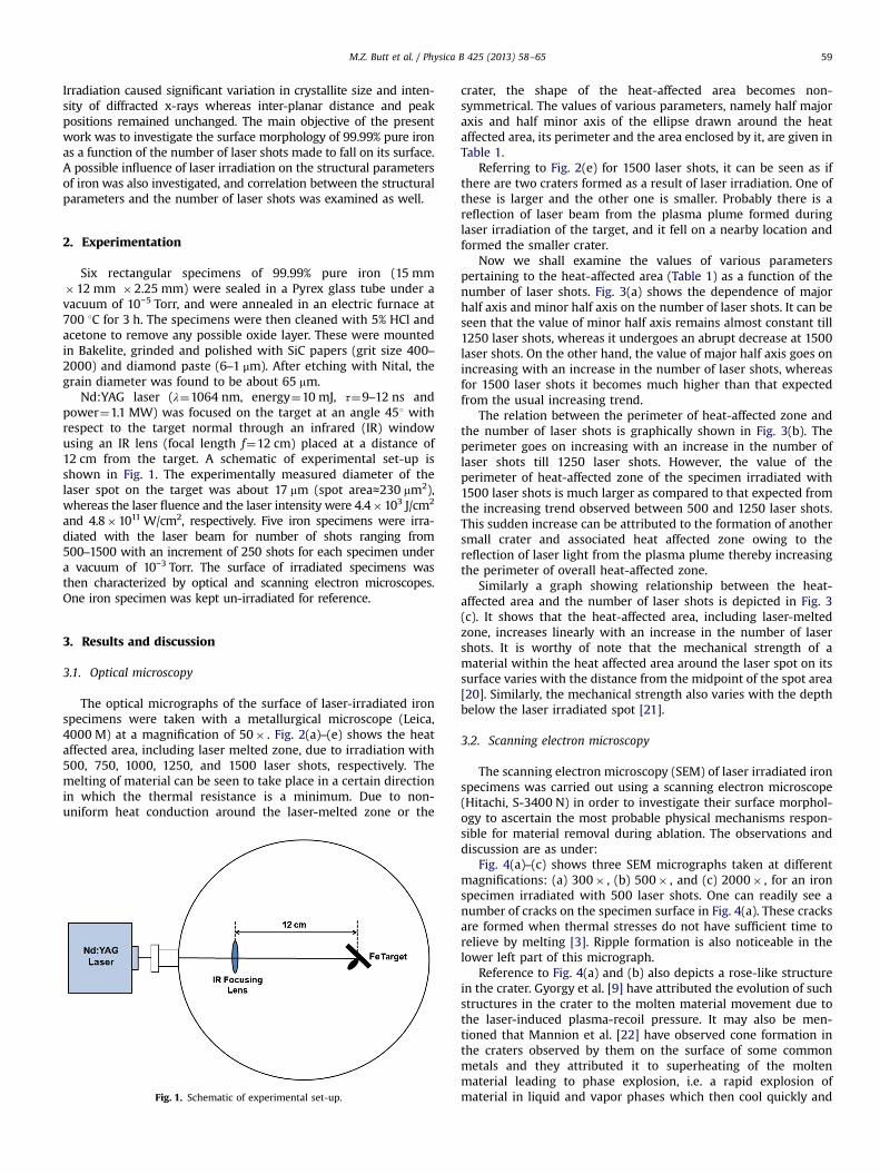
Nd:YAG laser (λ¼1064 nm, energy¼10 mJ, τ¼9–12 ns andpower¼1.1 MW) was focused on the target at an angle 451 withrespect to the target normal through an infrared (IR) windowusing an IR lens (focal length f¼12 cm) placed at a distance of12 cm from the target. A schematic of experimental set-up isshown in Fig. 1. The experimentally measured diameter of thelaser spot on the target was about 17 mm (spot area≈230 mm2),whereas the laser fluence and the laser intensity were 4.4�103 J/cm2
and 4.8�1011 W/cm2, respectively. Five iron specimens were irra-diated with the laser beam for number of shots ranging from500–1500 with an increment of 250 shots for each specimen undera vacuum of 10−3 Torr. The surface of irradiated specimens wasthen characterized by optical and scanning electron microscopes.One iron specimen was kept un-irradiated for reference.
3. Results and discussion
3.1. Optical microscopy
The optical micrographs of the surface of laser-irradiated ironspecimens were taken with a metallurgical microscope (Leica,4000 M) at a magnification of 50� . Fig. 2(a)–(e) shows the heataffected area, including laser melted zone, due to irradiation with500, 750, 1000, 1250, and 1500 laser shots, respectively. Themelting of material can be seen to take place in a certain directionin which the thermal resistance is a minimum. Due to non-uniform heat conduction around the laser-melted zone or the
Fig. 1. Schematic of experimental set-up.
crater, the shape of the heat-affected area becomes non-symmetrical. The values of various parameters, namely half majoraxis and half minor axis of the ellipse drawn around the heataffected area, its perimeter and the area enclosed by it, are given inTable 1.
Referring to Fig. 2(e) for 1500 laser shots, it can be seen as ifthere are two craters formed as a result of laser irradiation. One ofthese is larger and the other one is smaller. Probably there is areflection of laser beam from the plasma plume formed duringlaser irradiation of the target, and it fell on a nearby location andformed the smaller crater.
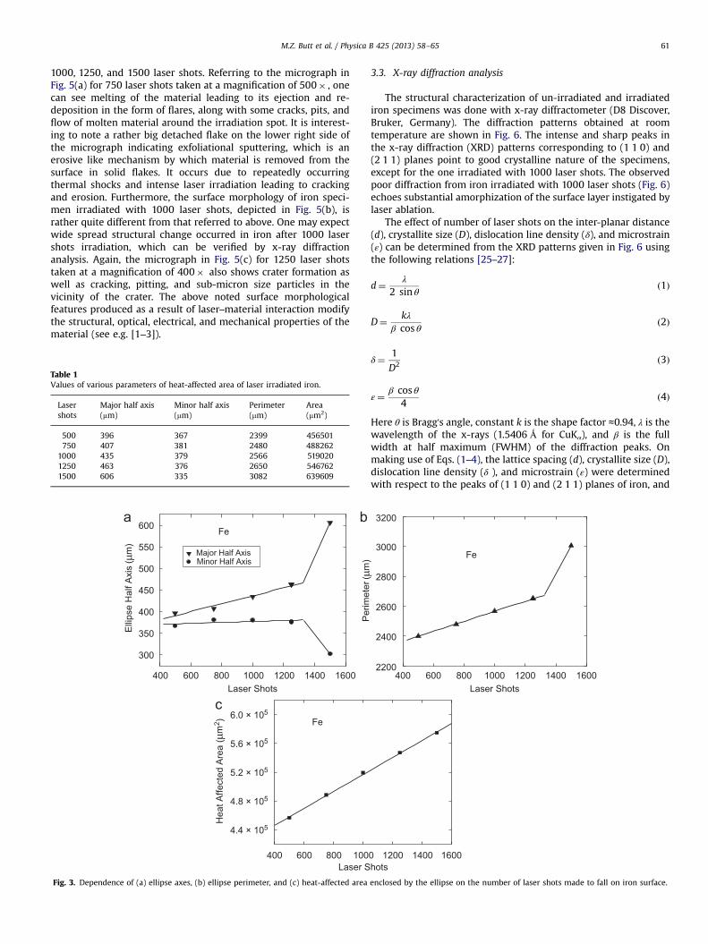
Now we shall examine the values of various parameterspertaining to the heat-affected area (Table 1) as a function of thenumber of laser shots. Fig. 3(a) shows the dependence of majorhalf axis and minor half axis on the number of laser shots. It can beseen that the value of minor half axis remains almost constant till1250 laser shots, whereas it undergoes an abrupt decrease at 1500laser shots. On the other hand, the value of major half axis goes onincreasing with an increase in the number of laser shots, whereasfor 1500 laser shots it becomes much higher than that expectedfrom the usual increasing trend.
The relation between the perimeter of heat-affected zone andthe number of laser shots is graphically shown in Fig. 3(b). Theperimeter goes on increasing with an increase in the number oflaser shots till 1250 laser shots. However, the value of theperimeter of heat-affected zone of the specimen irradiated with1500 laser shots is much larger as compared to that expected fromthe increasing trend observed between 500 and 1250 laser shots.This sudden increase can be attributed to the formation of anothersmall crater and associated heat affected zone owing to thereflection of laser light from the plasma plume thereby increasingthe perimeter of overall heat-affected zone.
Similarly a graph showing relationship between the heat-affected area and the number of laser shots is depicted in Fig. 3(c). It shows that the heat-affected area, including laser-meltedzone, increases linearly with an increase in the number of lasershots. It is worthy of note that the mechanical strength of amaterial within the heat affected area around the laser spot on itssurface varies with the distance from the midpoint of the spot area[20]. Similarly, the mechanical strength also varies with the depthbelow the laser irradiated spot [21].
3.2. Scanning electron microscopy
The scanning electron microscopy (SEM) of laser irradiated ironspecimens was carried out using a scanning electron microscope(Hitachi, S-3400 N) in order to investigate their surface morphol-ogy to ascertain the most probable physical mechanisms respon-sible for material removal during ablation. The observations anddiscussion are as under:
Fig. 4(a)–(c) shows three SEM micrographs taken at differentmagnifications: (a) 300� , (b) 500� , and (c) 2000� , for an ironspecimen irradiated with 500 laser shots. One can readily see anumber of cracks on the specimen surface in Fig. 4(a). These cracksare formed when thermal stresses do not have sufficient time torelieve by melting [3]. Ripple formation is also noticeable in thelower left part of this micrograph.
Reference to Fig. 4(a) and (b) also depicts a rose-like structurein the crater. Gyorgy et al. [9] have attributed the evolution of suchstructures in the crater to the molten material movement due tothe laser-induced plasma-recoil pressure. It may also be men-tioned that Mannion et al. [22] have observed cone formation inthe craters observed by them on the surface of some commonmetals and they attributed it to superheating of the moltenmaterial leading to phase explosion, i.e. a rapid explosion ofmaterial in liquid and vapor phases which then cool quickly and
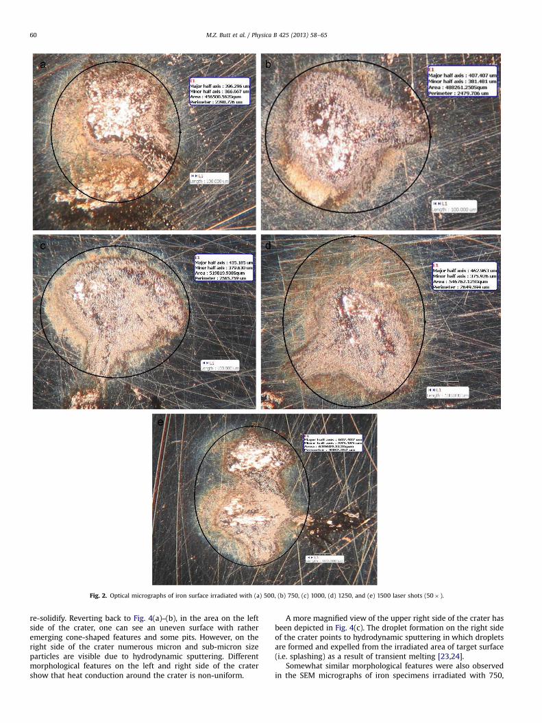
Fig. 2. Optical micrographs of iron surface irradiated with (a) 500, (b) 750, (c) 1000, (d) 1250, and (e) 1500 laser shots (50� ).
M.Z. Butt et al. / Physica B 425 (2013) 58–6560
re-solidify. Reverting back to Fig. 4(a)–(b), in the area on the leftside of the crater, one can see an uneven surface with ratheremerging cone-shaped features and some pits. However, on theright side of the crater numerous micron and sub-micron sizeparticles are visible due to hydrodynamic sputtering. Differentmorphological features on the left and right side of the cratershow that heat conduction around the crater is non-uniform.
A more magnified view of the upper right side of the crater hasbeen depicted in Fig. 4(c). The droplet formation on the right sideof the crater points to hydrodynamic sputtering in which dropletsare formed and expelled from the irradiated area of target surface(i.e. splashing) as a result of transient melting [23,24].
Somewhat similar morphological features were also observedin the SEM micrographs of iron specimens irradiated with 750,
M.Z. Butt et al. / Physica B 425 (2013) 58–65 61
1000, 1250, and 1500 laser shots. Referring to the micrograph inFig. 5(a) for 750 laser shots taken at a magnification of 500� , onecan see melting of the material leading to its ejection and re-deposition in the form of flares, along with some cracks, pits, andflow of molten material around the irradiation spot. It is interest-ing to note a rather big detached flake on the lower right side ofthe micrograph indicating exfoliational sputtering, which is anerosive like mechanism by which material is removed from thesurface in solid flakes. It occurs due to repeatedly occurringthermal shocks and intense laser irradiation leading to crackingand erosion. Furthermore, the surface morphology of iron speci-men irradiated with 1000 laser shots, depicted in Fig. 5(b), israther quite different from that referred to above. One may expectwide spread structural change occurred in iron after 1000 lasershots irradiation, which can be verified by x-ray diffractionanalysis. Again, the micrograph in Fig. 5(c) for 1250 laser shotstaken at a magnification of 400� also shows crater formation aswell as cracking, pitting, and sub-micron size particles in thevicinity of the crater. The above noted surface morphologicalfeatures produced as a result of laser–material interaction modifythe structural, optical, electrical, and mechanical properties of thematerial (see e.g. [1‒3]).
Table 1Values of various parameters of heat-affected area of laser irradiated iron.
Lasershots
Major half axis(mm)
Minor half axis(mm)
Perimeter(mm)
Area(mm2)
500 396 367 2399 456501750 407 381 2480 488262
1000 435 379 2566 5190201250 463 376 2650 5467621500 606 335 3082 639609
Fig. 3. Dependence of (a) ellipse axes, (b) ellipse perimeter, and (c) heat-affected area
3.3. X-ray diffraction analysis
The structural characterization of un-irradiated and irradiatediron specimens was done with x-ray diffractometer (D8 Discover,Bruker, Germany). The diffraction patterns obtained at roomtemperature are shown in Fig. 6. The intense and sharp peaks inthe x-ray diffraction (XRD) patterns corresponding to (1 1 0) and(2 1 1) planes point to good crystalline nature of the specimens,except for the one irradiated with 1000 laser shots. The observedpoor diffraction from iron irradiated with 1000 laser shots (Fig. 6)echoes substantial amorphization of the surface layer instigated bylaser ablation.
The effect of number of laser shots on the inter-planar distance(d), crystallite size (D), dislocation line density (δ), and microstrain(ε) can be determined from the XRD patterns given in Fig. 6 usingthe following relations [25–27]:
d¼ λ
2 sin θð1Þ
D¼ kλβ cos θ
ð2Þ
δ¼ 1
D2 ð3Þ
ε¼ β cos θ4
ð4Þ
Here θ is Bragg's angle, constant k is the shape factor ≈0.94, λ is thewavelength of the x-rays (1.5406 Ǻ for CuKα), and β is the fullwidth at half maximum (FWHM) of the diffraction peaks. Onmaking use of Eqs. (1–4), the lattice spacing (d), crystallite size (D),dislocation line density (δ ), and microstrain (ε) were determinedwith respect to the peaks of (1 1 0) and (2 1 1) planes of iron, and
enclosed by the ellipse on the number of laser shots made to fall on iron surface.

Fig. 4. SEM micrographs of iron surface irradiated with 500 laser shots: (a) 300� ,(b) 500� , and 2000� .
Fig. 5. SEM micrographs of iron surface irradiated with (a) 750, (b) 1000, and(c) 1250 laser shots.
M.Z. Butt et al. / Physica B 425 (2013) 58–6562
their values along with the diffraction peak intensity (I) are givenin Tables 2–3.
Reference to Fig. 7(a) shows correlation between the intensityof x-rays diffracted from (1 1 0) and (2 1 1) planes and the numberof laser shots incident on the iron target. The intensity valuespertaining to (1 1 0) plane are higher than those for (2 1 1) planein the entire laser shots range 0–1500. This shows that (1 1 0) isthe preferential orientation of the crystallographic planes in theiron targets whether un-irradiated or irradiated. It is interesting tonote that intensity of x-rays diffracted from (1 1 0) and (2 1 1)
planes increases with the number of laser shots to begin with, andthen falls to a minimum value for 1000 laser shots, and again risesmonotonically with the number of laser shots up to 1500. Theminimum in the intensity versus laser shots curves correspondingto 1000 laser shots indicates that substantial amorphoization hasoccurred in the target. The intensity of the (2 1 1) peak was sosmall that FWHM of this peak was not measureable. However, anincrease in the diffraction intensity for both (1 1 0) and (2 1 1)peaks later on may be due to laser induced melting andrecrystallization.
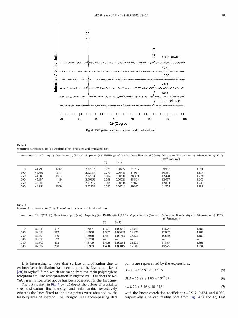
Fig. 6. XRD patterns of un-irradiated and irradiated iron.
Table 2Structural parameters for (1 1 0) plane of un-irradiated and irradiated iron.
Laser shots 2θ of (1 1 0) (1) Peak intensity (I) (cps) d-spacing (Å) FWHM (β) of (1 1 0) Crystallite size (D) (nm) Dislocation line density (δ)(1014 lines/m2)
Microstrain (ε) (10−3)
(1) (rad)
0 44.795 1242 2.02162 0.271 0.00472 31.755 9.917 1.091500 44.792 1841 2.02175 0.277 0.00483 31.067 10.361 1.115750 44.808 1853 2.02108 0.304 0.00530 28.309 12.478 1.224
1000 45.197 149 2.00456 0.299 0.00521 28.823 12.037 1.2021250 45.008 711 2.01256 0.309 0.00538 27.871 12.873 1.2431500 44.754 1609 2.02339 0.295 0.00514 29.167 11.755 1.188
Table 3Structural parameters for (211) plane of un-irradiated and irradiated iron.
Laser shots 2θ of (211) (1) Peak intensity (I) (cps) d-spacing (Å) FWHM (β) of (2 1 1) Crystallite size (D) (nm) Dislocation line density (δ)(1014 lines/m2)
Microstrain (ε) (10−3)
(1) (rad)
0 82.340 537 1.17014 0.391 0.00681 27.043 13.674 1.282500 82.393 762 1.16950 0.367 0.00639 28.823 12.037 1.203750 82.399 319 1.16940 0.421 0.00733 25.127 15.839 1.380
1000 83.070 52 1.16250 — — — — —
1250 82.602 133 1.16709 0.490 0.00854 21.622 21.389 1.6031500 82.392 230 1.16953 0.468 0.00815 22.602 19.575 1.534
M.Z. Butt et al. / Physica B 425 (2013) 58–65 63
It is interesting to note that surface amorphization due toexcimer laser irradiation has been reported by Lazare and Benet[28] in Mylars films, which are made from the resin polyethyleneterephthalate. The amorphization instigated by 1000 shots of Nd:YAG laser in iron cited above has been observed for the first time.
The data points in Fig. 7(b)–(d) depict the values of crystallitesize, dislocation line density, and microstrain, respectively,whereas the lines fitted to the data points were obtained by theleast-squares fit method. The straight lines encompassing data
points are represented by the expressions:
D¼ 11:45–2:81� 10−2 LS ð5Þ
DLD¼ 15:33þ 1:65� 10−2 LS ð6Þ
ε¼ 8:72þ 5:46� 10−2 LS ð7Þwith the linear correlation coefficient r¼0.912, 0.824, and 0.980,respectively. One can readily note from Fig. 7(b) and (c) that
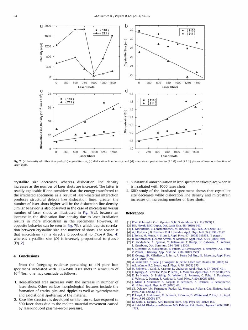
Fig. 7. (a) Intensity of diffraction peak, (b) crystallite size, (c) dislocation line density, and (d) microstrain pertaining to (1 1 0) and (2 1 1) planes of iron as a function oflaser shots.
M.Z. Butt et al. / Physica B 425 (2013) 58–6564
crystallite size decreases, whereas dislocation line densityincreases as the number of laser shots are increased. The latter isreadily explicable if one considers that the energy transferred tothe irradiated specimens as a result of laser–material interactionproduces structural defects like dislocation lines; greater thenumber of laser shots higher will be the dislocation line density.Similar behavior is also observed in the case of microstrain versusnumber of laser shots, as illustrated in Fig. 7(d), because anincrease in the dislocation line density due to laser irradiationresults in more microstrain in the specimens. However, anopposite behavior can be seen in Fig. 7(b), which depicts correla-tion between crystallite size and number of shots. The reason isthat microstrain (ε) is directly proportional to β cos θ (Eq. 4)whereas crystallite size (D) is inversely proportional to β cos θ(Eq. 2).
4. Conclusions
From the foregoing evidence pertaining to 4 N pure ironspecimens irradiated with 500–1500 laser shots in a vacuum of10−3 Torr, one may conclude as follows:
1.
Heat-affected area increases with the increase in number oflaser shots. Other surface morphological features include theformation of cracks, pits, and ripples as well as hydrodynamicand exfolational sputtering of the material.2.
Rose-like structure is developed on the iron surface exposed to500 laser shots due to the molten material movement causedby laser-induced plasma-recoil pressure.3.
Substantial amorphization in iron specimen takes place when itis irradiated with 1000 laser shots.4.
XRD study of the irradiated specimens shows that crystallitesize decreases while dislocation line density and microstrainincreases on increasing number of laser shots.References
[1] K.W. Kolasinski, Curr. Opinion Solid State Mater. Sci. 13 (2009) 1.[2] B.K. Nayak, M.C. Gupta, Opt. Laser Eng. 48 (2010) 940.[3] E. Morintable, C. Constantinescu, M. Dineseu, Phys. AUC 20 (2010) 43.[4] A.J. Pedraza, J.D. Fowlkes, D.H. Lowndes, Appl. Phys. Lett. 74 (1999) 2322.[5] J. Bonse, M. Munz, H. Stum, J. Appl. Phys. 97 (2005) 013538. (9 pages).[6] R. Karimzadeh, J. Zamir Anvari, N. Mansour, Appl. Phys. A 94 (2009) 949.[7] C. Yaddadene, A. Djemaa, Y. Belaroussi, T. Kerdja, N. Gabouze, A. Keffous,
L. Guerbous, Opt. Commun. 284 (2011) 3308.[8] S. Lugomer, A. Maksimović, B. Farkas, Z. Geretovszky, T. Szörényi, A.L. Tóth,
Z. Zolnai, I. Bársony, Appl. Surf. Sci. 258 (2012) 3589.[9] E. Gyorgy, I.N. Mihailescu, P. Serra, A. Perez Del Pino, J.L. Morenza, Appl. Phys.
A 74 (2002) 755.[10] A. Semeroke, B. Salle, J.F. Wagner, G. Petite, Laser Part. Beams 20 (2002) 67.[11] A.E. Wynne, R.C. Stuart, Appl. Phys. A 76 (2003) 373.[12] H. Reimers, J. Gold, B. Kasemo, D. Chakarov, Appl. Phys. A 77 (2003) 491.[13] E. Gyorgy, A. Perez Del Pino, P. Serra, J.L. Morenza, Appl. Phys. A 78 (2004) 765.[14] R. Le Harzic, D. Breitling, M. Weikert, S. Sommer, C. Fohd, F. Dausinger,
S. Valette, C. Donnet, E. Audouard, Appl. Phys. A 80 (2005) 1589.[15] J. Maul, I. Strachnov, S. Karpuk, P. Bernhard, A. Oelsner, G. Schonhense,
G. Huber, Appl. Phys. A 82 (2006) 43.[16] S.I. Dolgaev, J.M. Fernandez-Pradas, J.L. Morenza, P. Serra, G.A. Shafeev, Appl.
Phys. A 83 (2006) 417.[17] R. Lloyd, A. Abdolvand, M. Schmidt, P. Crouse, D. Whitehead, Z. Liu, L. Li, Appl.
Phys. A 93 (2008) 117.[18] M. Stafe, C. Negutu, A.N. Ducariu, Rom. Rep. Phys. 64 (2012) 155.[19] A. Latif, M. Khaleeq-ur-Rahman, M.S. Rafique, K.A. Bhatti, Physica B 406 (2011)
1713.

M.Z. Butt et al. / Physica B 425 (2013) 58–65 65
[20] M.Z. Butt, F. Bashir, S. Arooj, Appl. Surf. Sci. 259 (2012) 740.[21] M. Khaleeq-ur-Rahman, M.Z. Butt, A. Samuel, K. Siraj, Vacuum 85 (2010) 474.[22] P.T. Mannion, J. Magee, E. Coune, G.M. Oconnor, T.J. Glynn, Appl. Surf. Sci. 233
(2004) 275.[23] D.B. Chrisey, G.K. Hubler (Eds.), Pulsed Laser Deposition of Thin Films, John
Wiley & Sons Inc., New York, 1994.[24] J.C. Miller, R.F. Haglund, Laser Ablation and Desorption, Academic Press, New
York, 1998.
[25] B.D. Cullity, S.R. Stock, Elements of X-ray diffraction, 3rd ed., New Jersy:Printic, Hall, 2001.
[26] R. Sathyamoorthy, C. Sharmila, K. Natarjan, S. Velumani, Mater. Character. 58(2007) 745.
[27] N.J.S. Kissinger, M. Jayachandran, K. Perumal, C.S. Raja, Bull. Mater. Sci. 30(2007) 547.
[28] S. Lazare, P. Benet, J. Appl. Phys. 74 (1993) 4953. (5 pages).
Related Documents


![Pulsed Nd:YAG laser induced high throughput stereospecific ... · Pulsed Nd:YAG laser induced high throughput stereospecific [2+2] cycloaddition of highly organized 1,2-bis(4-pyridyl)ethylene](https://static.cupdf.com/doc/110x72/5f109e017e708231d449fcbd/pulsed-ndyag-laser-induced-high-throughput-stereospecific-pulsed-ndyag-laser.jpg)