Supplement on Verilog adder examples Based on Fundamentals of Digital Logic with Verilog Design By Brown/Vranesic 3 rd . Chung-Ho Chen 1

Welcome message from author
This document is posted to help you gain knowledge. Please leave a comment to let me know what you think about it! Share it to your friends and learn new things together.
Transcript

1
Supplement on Verilogadder examples
Based on Fundamentals of Digital Logic with Verilog Design
By Brown/Vranesic 3rd.
Chung-Ho Chen

2
Describe a circuit in a form of module Gate Level
module mux (x1, x2, s, f);input x1, x2, s;output f;
not (si,s); and (u, si, x1);and (l, s, x2);or (f, u, l);
endmodule
output
keyword
and (u, ~s, x1); // without an explicit not ahead
3
Behavioral: logic equation
module mux (x1, x2, s, f);input x1, x2, s;output f;
assign f = (~s & x1) | (s &x2);assign y = f | x2;
endmodule
Continuous assignment:f is re-evaluated wheneverthe right hand side signal changes.
No order for f and y,concurrent statement;assign: for nets (like wire) since nets can nothold values, so you need to assign the value continuously.

4
Behavioral: procedural statement
module mux (x1, x2, s, f);input x1, x2, s;output f;reg f;
always@(x1 or x2 or s)if (s == 0)
f = x1;else
f = x2;
endmodule
always@(sensitivity list)
Evaluated in the order given by the code; if first, then else.= blocking assignment(evaluated in order)
5
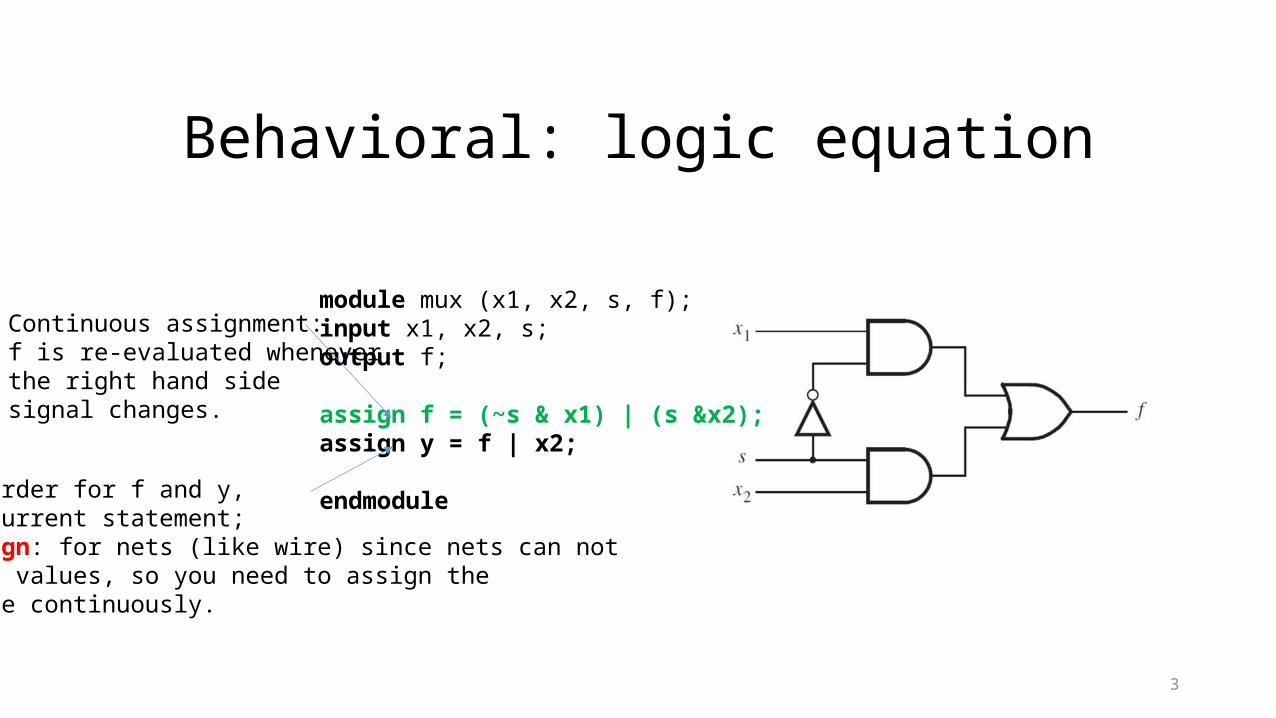
Coding in 3 ways:
• Gate instantiation • Continuous assignment (assign)• Procedural statements (always)
• Blocking assignment = sequencing • S = X + Y;• C = S[0]; // C takes the new value from X+Y.
• Non-blocking assignment <= • S <= X + Y;• C <= S[0]; // at simulation time ti, C takes the value of S[0] at simulation time ti-1

6
More compact procedural statement
module mux (input x1, x2, s, output reg f);
always@(x1, x2,s)if (s == 0)
f = x1;else
f = x2;
endmodule

7
Hierarchical Verilog Code
X1
X2
ABCDE
a
b
c
d
y1
y2
abcde
module front (a, b, c, d);Input a, b;output c, d;…..endmodule
module back (y1, y2, a, b, c, d, e);Input y1, y2;output a, b, c, d, e;…..endmodule
w0
w1
module whole (X1, X2, A, B, C, D, E);Input X1, X2;output A, B, C, D, E;wire w0, w1;
front U1 (X1, X2, w0, w1);back U2 (w0, w1, A, B, C, D, E);…..endmodule
Top-level module
Internal (not output or input) uses wire.

8
Full Adder Using Gates
module fulladd (Cin, x, y, s, Cout);input Cin, x, y;output s, Cout;
xor (s, x, y, Cin);and (a, x, y);and (b, x, Cin);and (c, y, Cin);or (Cout, a, b, c);
endmodule
0 0 0 1 0 1 1 1
c i 1 +
0 0 0 0 1 1 1 1
0 0 1 1 0 0 1 1
0 1 0 1 0 1 0 1
c i x i y i
00 01 11 10
0
1
x i y i c i
1
1
1
1
s i x i y i c i =
00 01 11 10
0
1
x i y i c i
1
1 1 1
c i 1 + x i y i x i c i y i c i + + =
c i
x i
y i s i
c i 1 +
(a) Truth table
(b) Karnaugh maps
(c) Circuit
0 1 1 0 1 0 0 1
s i
module fulladd (Cin, x, y, s, Cout);
input Cin, x, y;output s, Cout;
xor (s, x, y, Cin);and (a, x, y), (b, x, Cin),
//omit and (c, y, Cin);or (Cout, a, b, c);
endmodule

9
Full Adder Using Functional Expression
0 0 0 1 0 1 1 1
c i 1 +
0 0 0 0 1 1 1 1
0 0 1 1 0 0 1 1
0 1 0 1 0 1 0 1
c i x i y i
00 01 11 10
0
1
x i y i c i
1
1
1
1
s i x i y i c i =
00 01 11 10
0
1
x i y i c i
1
1 1 1
c i 1 + x i y i x i c i y i c i + + =
c i
x i
y i s i
c i 1 +
(a) Truth table
(b) Karnaugh maps
(c) Circuit
0 1 1 0 1 0 0 1
s i
module fulladd (Cin, x, y, s, Cout);
input Cin, x, y;
output s, Cout;
assign s = x ^ y ^ Cin,
Cout = (x & y) | (x & Cin) | (y & Cin);
endmodule

10
3-bit Ripple Addersmodule adder3 (c0, x2, x1, x0, y2, y1, y0, s2, s1, s0, carryout);
input c0, x2, x1, x0, y2, y1, y0;output s2, s1, s0, carryout;
fulladd b0 (c0, x0, y0, s0, c1);fulladd b1 (c1, x1, y1, s1, c2);fulladd b2 (c2, x2, y2, s2, carryout);
endmodule module fulladd (Cin, x, y, s, Cout);
input Cin, x, y;output s, Cout;
assign s = x ^ y ^ Cin,assign Cout = (x & y) | (x & Cin) | (y & Cin);
endmodule
Instantiate thefulladd module
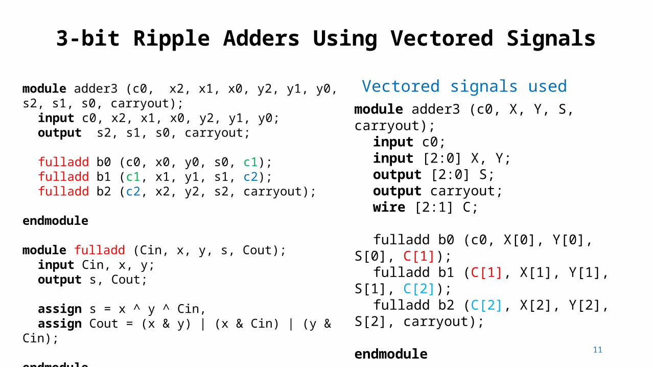
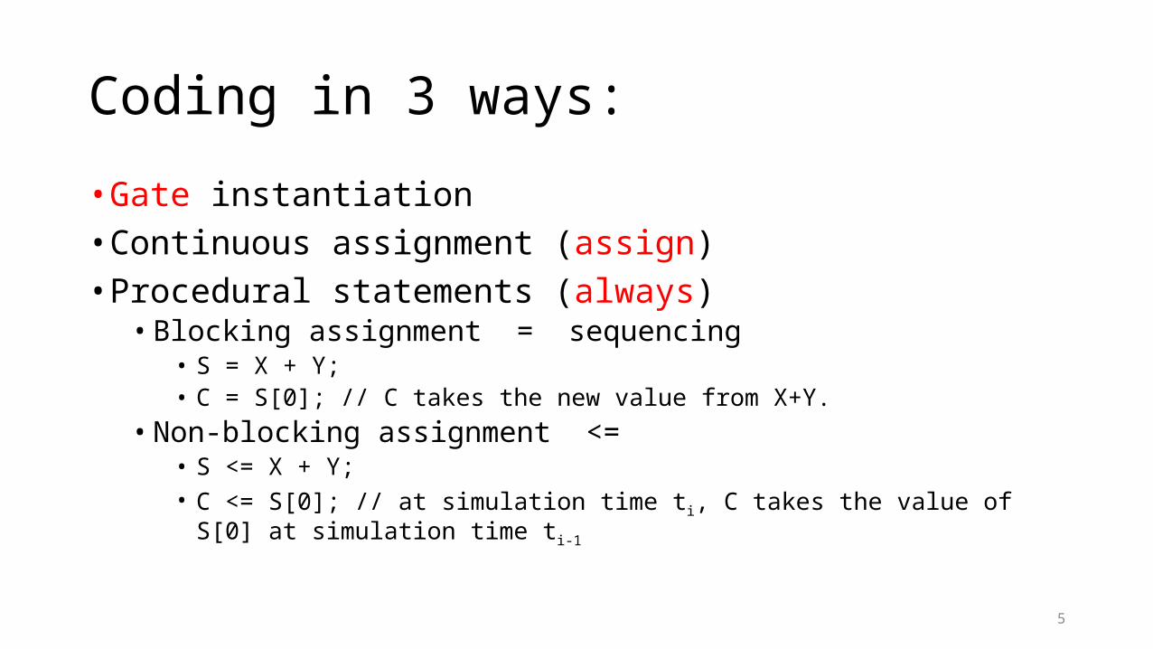
3-bit Ripple Adders Using Vectored Signals
11
module adder3 (c0, x2, x1, x0, y2, y1, y0, s2, s1, s0, carryout);input c0, x2, x1, x0, y2, y1, y0;output s2, s1, s0, carryout;
fulladd b0 (c0, x0, y0, s0, c1);fulladd b1 (c1, x1, y1, s1, c2);fulladd b2 (c2, x2, y2, s2, carryout);
endmodule module fulladd (Cin, x, y, s, Cout);
input Cin, x, y;output s, Cout;
assign s = x ^ y ^ Cin,assign Cout = (x & y) | (x & Cin) | (y & Cin);
endmodule
module adder3 (c0, X, Y, S, carryout);input c0;input [2:0] X, Y;output [2:0] S;output carryout;wire [2:1] C;
fulladd b0 (c0, X[0], Y[0], S[0], C[1]);fulladd b1 (C[1], X[1], Y[1], S[1], C[2]);fulladd b2 (C[2], X[2], Y[2], S[2], carryout);
endmodule
Vectored signals used
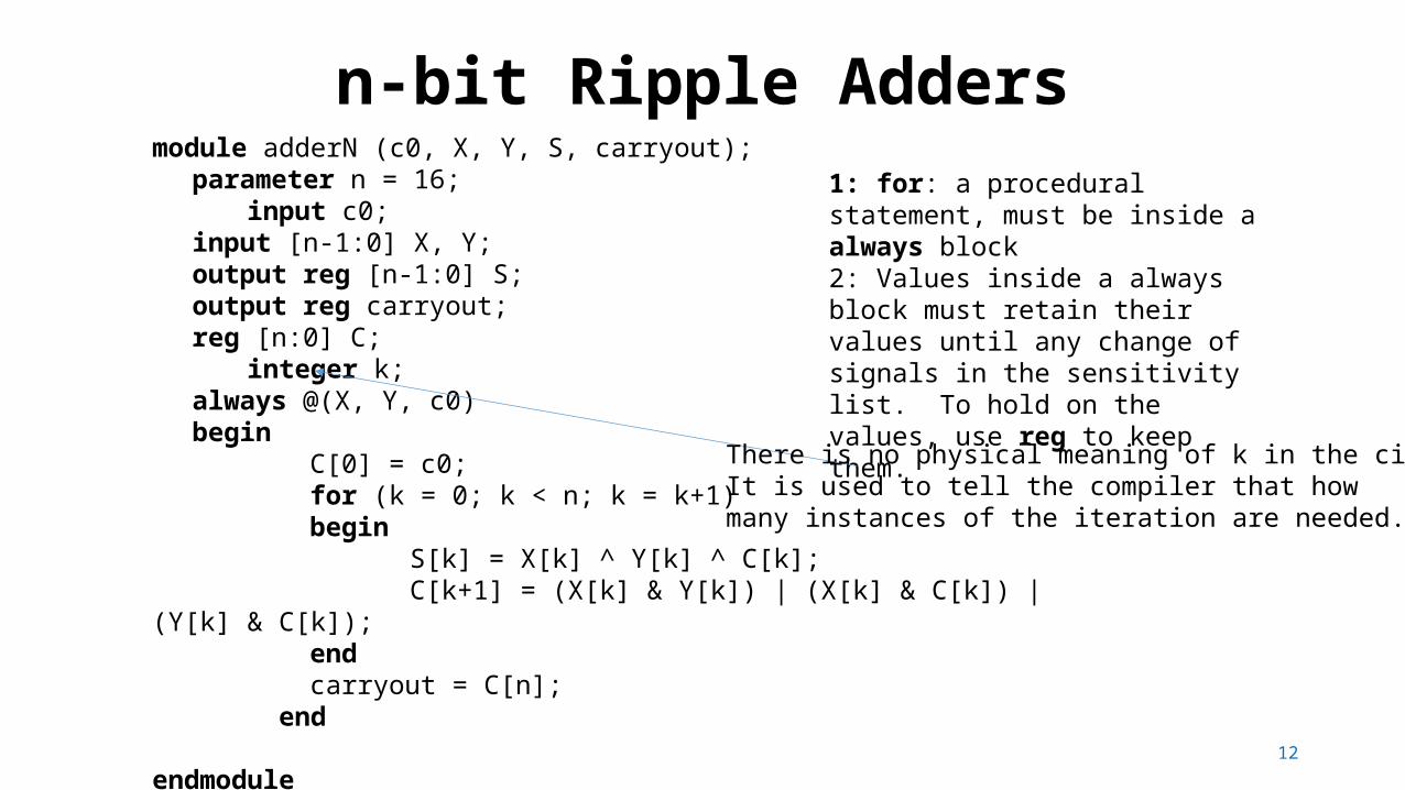
n-bit Ripple Adders
12
module adderN (c0, X, Y, S, carryout);parameter n = 16;
input c0;input [n-1:0] X, Y;output reg [n-1:0] S;output reg carryout;reg [n:0] C;
integer k;always @(X, Y, c0)begin
C[0] = c0;for (k = 0; k < n; k = k+1)begin
S[k] = X[k] ^ Y[k] ^ C[k];C[k+1] = (X[k] & Y[k]) | (X[k] & C[k]) | (Y[k] & C[k]);
endcarryout = C[n];
end
endmodule
1: for: a procedural statement, must be inside a always block 2: Values inside a always block must retain their values until any change of signals in the sensitivity list. To hold on the values, use reg to keep them.
There is no physical meaning of k in the circuit.It is used to tell the compiler that howmany instances of the iteration are needed.

3-bit to n-bit transformation using generate
13
module adder3 (c0, X, Y, S, carryout);input c0;input [2:0] X, Y;output [2:0] S;output carryout;wire [2:1] C;
fulladd b0 (c0, X[0], Y[0], S[0], C[1]);fulladd b1 (C[1], X[1], Y[1], S[1], C[2]);fulladd b2 (C[2], X[2], Y[2], S[2], carryout);
endmodule
module addern (c0, X, Y, S, carryout); parameter n = 16; input c0; input [n-1:0] X, Y; output [n-1:0] S; output carryout; wire [n:0] C;
genvar i; // to be used in generate assign C[0] = c0; assign carryout = C[n]; generate for (i = 0; i <= n-1; i = i+1) begin:adderbit fulladd b (C[i], X[i], Y[i], S[i], C[i+1]); end endgenerateendmodule
Instantiate a submodule n times usinggenerate
Instance name producedadderbit[0].badderbit[1].b….adderbit[15].b

Overflow and Carry-Out detection
14
For unsigned numbercarry out from n-1 bit position:
If both xn-1 and yn-1 are 1 orIf either xn-1 or yn-1 is 1 and sn-1 is 0.
Hence, carryout = xn-1 yn-1 + ~sn-1 xn-1 + ~sn-1 yn-1
n-bit signed number: -2n-1 to 2n-1 -1Detect overflow for signed number:
Overflow = Cn-1 ⊕ Cn
Overflow = Xn-1 Yn-1 ~Sn-1 (110) + ~Xn-1 ~Yn-1 Sn-1 (001)
(summation of two same signs produce different sign)
where X and Y represent the 2’s complement numbers, S = X+Y. (sign bits 0, 0 ≠ 1 )
011101111111

15
n-bit adder with overflow and carryout
module addern (carryin, X, Y, S, carryout, overflow);parameter n = 32;input carryin;input [n-1:0] X, Y;output reg [n-1:0] S;output reg carryout, overflow;
always @(X, Y, carryin)begin
S = X + Y + carryin; // arithmetic assignment carryout = (X[n-1] & Y[n-1]) | (X[n-1] & ~S[n-1]) | (Y[n-1] & ~S[n-1]);overflow = (X[n-1] & Y[n-1] & ~S[n-1]) | (~X[n-1] & ~Y[n-1] & S[n-1]);
end endmodule

16
Another way to get carryoutmodule addern (carryin, X, Y, S, carryout, overflow);
parameter n = 32;input carryin;input [n-1:0] X, Y;output reg [n-1:0] S;output reg carryout, overflow;reg [n:0] Sum; //n+1 bits, nth for the carryout
always @(X, Y, carryin)begin
Sum = {1'b0,X} + {1'b0,Y} + carryin; // One 0 bit is concatenated (,) with X S = Sum[n-1:0];carryout = Sum[n];overflow = (X[n-1] & Y[n-1] & ~S[n-1]) | (~X[n-1] & ~Y[n-1] & S[n-1]);
end endmodule
Will this work?Sum = X + Y + carryin;?
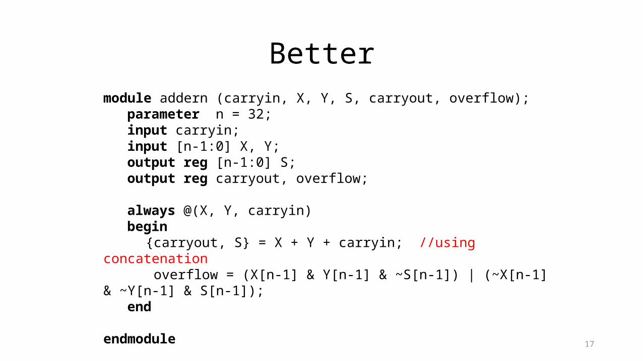
17
Bettermodule addern (carryin, X, Y, S, carryout, overflow);
parameter n = 32;input carryin;input [n-1:0] X, Y;output reg [n-1:0] S;output reg carryout, overflow;
always @(X, Y, carryin)begin
{carryout, S} = X + Y + carryin; //using concatenation overflow = (X[n-1] & Y[n-1] & ~S[n-1]) | (~X[n-1] & ~Y[n-1] & S[n-1]);
end endmodule

18
Module Hierarchy in Verilogtwo adders: 16-bit and 8-bit
module addern (carryin, X, Y, S, carryout, overflow);parameter n = 32;input carryin;input [n-1:0] X, Y;output reg [n-1:0] S;output reg carryout, overflow;
always @(X, Y, carryin)begin
{carryout, S} = X + Y + carryin; overflow = (X[n-1] & Y[n-1] & ~S[n-
1]) | (~X[n-1] & ~Y[n-1] & S[n-1]);end
endmodule
module adder_hier (A, B, C, D, S, T, overflow);input [15:0] A, B;input [7:0] C, D;output [16:0] S;output [8:0] T;output overflow;
wire v1, v2; // used for the overflow signals
addern U1 (1’b0, A, B, S[15:0], S[16], v1);defparam U1.n = 16;addern U2 (1’b0, C, D, T[7:0], T[8], v2);defparam U2.n = 8;
assign overflow = v1 | v2; endmodule
defparam: define n to be 16
S[16] and T[8] forunsigned carryout

19
Specifying Parameterstwo adders: 16-bit and 8-bit
module adder_hier (A, B, C, D, S, T, overflow);input [15:0] A, B;input [7:0] C, D;output [16:0] S;output [8:0] T;output overflow; // not in an always block
wire v1, v2; // used for the overflow signals
addern U1 (1’b0, A, B, S[15:0], S[16], v1);defparam U1.n = 16;addern U2 (1’b0, C, D, T[7:0], T[8], v2);defparam U2.n = 8;
assign overflow = v1 | v2; endmodule
addern #(16) U1 (1’b0, A, B, S[15:0], S[16], v1);
Using # operator.
20
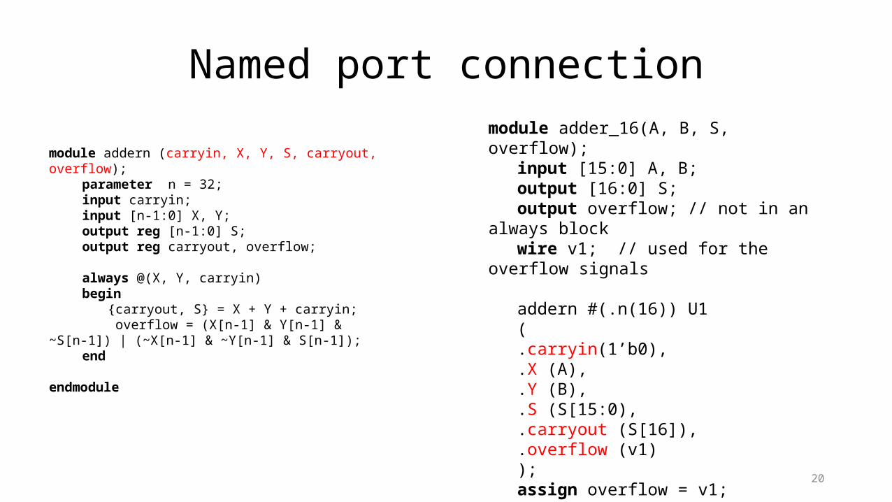
Named port connection
module addern (carryin, X, Y, S, carryout, overflow);parameter n = 32;input carryin;input [n-1:0] X, Y;output reg [n-1:0] S;output reg carryout, overflow;
always @(X, Y, carryin)begin
{carryout, S} = X + Y + carryin; overflow = (X[n-1] & Y[n-1] & ~S[n-1]) | (~X[n-1]
& ~Y[n-1] & S[n-1]);end
endmodule
module adder_16(A, B, S, overflow);input [15:0] A, B;output [16:0] S;output overflow; // not in an always blockwire v1; // used for the overflow signals
addern #(.n(16)) U1(.carryin(1’b0),.X (A),.Y (B),.S (S[15:0),.carryout (S[16]),.overflow (v1));assign overflow = v1;
endmodule
21
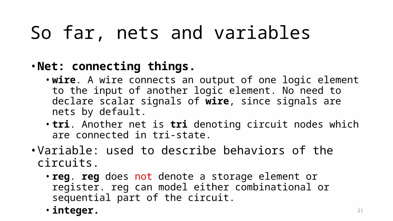
So far, nets and variables
• Net: connecting things.• wire. A wire connects an output of one logic element to the input of another
logic element. No need to declare scalar signals of wire, since signals are nets by default.
• tri. Another net is tri denoting circuit nodes which are connected in tri-state.
• Variable: used to describe behaviors of the circuits.• reg. reg does not denote a storage element or register. reg can model either
combinational or sequential part of the circuit.• integer.
Related Documents