Supervising Water Well Drilling A Guide for Supervisors Rural Water Supply Network Field Note No 2012-2 Dotun Adekile 2012

Welcome message from author
This document is posted to help you gain knowledge. Please leave a comment to let me know what you think about it! Share it to your friends and learn new things together.
Transcript
Supervising Water Well Drilling
A Guide for Supervisors
Rural Water Supply Network Field Note No 2012-2
Dotun Adekile
2012
2
Field Note No 2012-2
Summary
Good supervision of water well drilling is essential for the provi-
sion of long-lasting water wells. This guidance note assists ge-
ologists and engineers in charge of the supervision of borehole
construction as well as project managers. It can be used to pre-
pare for training, and as a manual.
This guide details the responsibilities of the drilling supervisor at
the different stages of borehole construction. It explains the
actions to be carried out at each stage that will ensure that the
driller delivers the borehole as specified in the contract.
The supervisor is expected to display great professionalism in
carrying out his or her duties. A good knowledge of geology,
hydrogeology and borehole construction is essential. Although
the supervisor represents the client, he or she is expected to act
with honesty, impartiality and fairness in any dispute over the
contract. Young drilling supervisors need to be supported by
more experienced personnel.
The publication part of a series by RWSN on Cost Effective
Boreholes alongside:
Code of Practice for Cost Effective Boreholes (Danert et al,
2010)
Sustainable Groundwater Development: use, protect and
enhance (Furey, 2012)
Siting of Drilled Water Wells: A Guide for Project Managers
(Carter et al, 2011)
Costing and Pricing: A Guide for Water Well Drilling Enter-
prises (Danert et al, 2010)
Procurement and Contract Management of Drilled Well Con-
struction: A Guide for Supervisors and Project Managers (Ad-
ekile, 2012)
It is assumed that readers will have access to the other docu-
ments, all of which are available on the RWSN website
http://www-rural-water-supply.net.
Contents
Summary .............................................................................................................. 2
Introduction ........................................................................................................ 2
Principles of Drilling Supervision ............................................................... 3
Borehole Construction Workflow and Steps ......................................... 5
Step 1: Inspection .............................................................................. 6
Step 2: Borehole siting .................................................................... 6
Step 3: Pre-Mobilisation Meeting ............................................... 7
Step 4: Mobilisation .......................................................................... 7
Step 5: Drilling .................................................................................... 8
Step 6: On-site Design Modifications ..................................... 11
Step 7: Borehole development and site completion ........ 13
Step 8: Demobilisation .................................................................. 16
Step 9: Complete documentation and handover............... 16
Final Remarks .................................................................................................. 16
Glossary ............................................................................................................. 17
Annex A: Project Checklist for the Driller ................................... 18
Annex B: Checklists of Drilling Steps for the Supervisor ..... 19
Annex C: Circulation/Settling pits layout ................................... 23
Introduction
There is currently a big push to meet the Millennium Develop-
ment Goals target for drinking water. Soon the world may be
talking about universal access. Whilst this is positive, it is im-
portant that quality is not compromised in the drive to serve
more people. A poorly constructed borehole can fail after one
year, resulting in wasted investment and disappointed users. If
drilling and construction are not adequately supervised by
trained professionals, corners may be cut, quality will be com-
promised and services will fail. Governments, NGOs and agen-
cies have a responsibility to ensure that quality is not compro-
mised by a lack of drilling supervision.
Groundwater sources, namely wells and boreholes, are often the
first choice of water source for supplying rural areas. It is esti-
mated that 1.25 billion people directly use boreholes for their
drinking water (WHO/UNICEF 2012). If one assumes that 40% of
the sources for drinking water through piped supplies are from
boreholes, then 2.9 billion people (42% of the world’s popula-
tion) depend on drilled water wells. Groundwater sources are
found in most places and are relatively easy and cheap to install.
They are also not as prone to pollution as other sources of wa-
ter.
It is crucial that boreholes are delivered in a cost effective man-
ner. Cost effectiveness means getting the long-term best value
for money invested, i.e. boreholes continue to function through
the lifespan of 20 to 50 years. In some African countries, as
many as 60% of groundwater sources are not working. Poor
borehole construction contributes to this alarming figure. One
of the best ways to tackle this problem is to improve the quality
and professionalism of water well drilling including supervision.
Box 1: Why is good supervision important?
Abuja, Nigeria: The expected drilling depth was 35m. The Supervi-
sor was late to site. When he arrived the driller was already at 60m
depth, claiming little water was encountered at 35m and he had to
continue. It was obvious he was only doing it to earn more metres,
but it could not be proven. The clause in the contract that drilling
should not commence without the Supervisor on site could be
invoked but as a one-off case, the Driller’s claim was accepted.
Conclusion: the Supervisor should not keep the driller waiting.
Lagos, Nigeria: A telescopic design was specified. A large-diameter
hole was drilled, cased and grouted in, and then drilling through
the grout was performed with a smaller diameter bit. The grouting
failed, and an eruption of sand and water occurred. Two truck-
loads of sand were carted away from the site. The Driller said he
was not used to the method specified and he would have used
another method to achieve the design. A senior hydrogeologist in
the Ministry of Water Resources was asked to arbitrate. He blamed
the Supervisor for not using a pre-contract meeting to establish
the ability of the Driller to execute the design. He blamed the Drill-
er for not proposing a method within his competence. Conclusion:
establish a common understanding with the Driller, in writing, be-
fore drilling starts.
In 2010, the Rural Water Supply Network (RWSN) published the
Code of Practice for Cost Effective Boreholes based on interna-
tional best practices. The Code of Practice focuses on nine prin-
ciples (Box 2). These enable international organisations, private
enterprises and NGOs to evaluate their approach to borehole
delivery in accordance with good international practices. To
3
Field Note No 2012-2
strengthen the Code of Practice and support practitioners in the
practical application of the principles, RWSN is publishing de-
tailed guidance documents to cover all the principles.
This guidance note is part of the series and focuses on Supervi-
sion, which falls within Principle 6, which recommends that “Su-
pervision should be undertaken by government personnel or by
the private sector; additional expertise can be brought in to cover
capacity gaps with a view to build up long-term expertise”. RWSN
identified that there is a capacity gap in water well drilling su-
pervision. Hence this guide is aimed at inexperienced drilling
Supervisors e.g. fresh geology and engineering graduates, gen-
eral technicians and project managers. By applying this guid-
ance, the reader should be able to reduce overall drilling costs,
improve the quality of the finished borehole, and create a useful
set of written records that will help rural water supply service
managers operate and maintain that water source for many
years.
To get the most from this guide, the reader should have a good
knowledge of groundwater occurrence and drilling practices,
and use the guide in conjunction with the other Code of Practice
publications (listed in the summary on page 2). Note also the
glossary of technical terms (page 17), italicised in the text.
Box 2: Nine principles of Cost Effective Boreholes
1 Professional Drilling Enterprises and Consultants - Con-
struction of drilled water wells and supervision is undertaken
by professional and competent organisations which adhere to
national standards and are regulated by the public sector.
2 Siting - Appropriate siting practices are utilised and compe-
tently and scientifically carried out.
3 Construction Method - The construction method chosen for
the borehole is the most economical, considering the design
and available techniques in-country. Drilling technology needs
to match the borehole design.
4 Procurement - Procurement procedures ensure that contracts
are awarded to experienced and qualified consultants and
drilling contractors.
5 Design and Construction - The borehole design is cost effec-
tive, designed to last for a lifespan of 20 to 50 years, and
based on the minimum specification to provide a borehole
which is fit for its intended purpose.
6 Contract Management, Supervision and Payment - Ade-
quate arrangements are in place to ensure proper contract
management, supervision and timely payment of the drilling
contractor.
7 Data and Information – High-quality hydrogeological and
borehole construction data for each well are collected in a
standard format and submitted to the relevant government
authority.
8 Database and Record Keeping - Storage of hydrogeological
data is undertaken by a central Government institution with
records updated and information made freely available and
used in preparing subsequent drilling specifications.
9 Monitoring - Regular visits to water users with completed
boreholes are made to monitor functionality in the medium as
well as long-term, with the findings published.
Principles of Drilling Supervision
Aims, Roles and Responsibilities
The aim of supervising borehole drilling is to ensure that bore-
holes are produced as designed and all the data collected during
the drilling are accurately recorded and reported to the relevant
agencies. Good supervision is essential for a high quality bore-
hole, even if a competent drilling contractor (henceforth referred
to as the ‘Driller’) is employed. Without good supervision, the
quality of the work may be compromised. An experienced Driller
can easily hoodwink an inexperienced Supervisor. Supervisors
thus need to be trained and given the chance to acquire the
knowledge that will enable them carry out their duties.
Box 3: Drilling Roles and Responsibilities
The Community members are the end users of the water supply.
They must be included in the process of siting and design so that
the finished water point can meet their needs. There are cases
where the Community is involved in supervision, but they should
not be responsible for technical or contractual details unless their
capacity has been built extensively.
The Client is the organisation or community that is contracting out
the borehole construction. Their responsibility is to fulfil regulatory
requirements and ensure that they have well trained Supervisors
present on site for the full duration of drilling operations.
Note that even if district local government is not the client, it is
still important for them to be involved in the process. District local
government should attend the pre-mobilisation meeting as well as
the end of construction supervision.
The Funding Organisation pays for the borehole. It may be the
Client, or another organisation such as an international develop-
ment partner or NGO. The funding organisation should not impose
conditions that create perverse incentives or undermine the long-
term sustainability of the finished borehole (e.g. by insisting that
the cheapest bid is accepted regardless of quality). It should work
within national or local government systems.
The Regulator issues permits or licences for drilling or abstraction.
Legal requirements should be established by the Client early on to
avoid delays.
The Project Manager is usually responsible for a wider project.
The drilling will be just one component within a project plan com-
prising community training/mobilisation, pump technology choice,
water point design and construction, and establishing or strength-
ening a rural water supply service.
The Supervisor is sometimes called the ‘Rig Inspector’. Supervision
is usually done either by the Client’s staff or by a consultant. The
Supervisor may be a hydrogeologist, an engineer, or a technician.
Although the Driller and the Supervisor work together to deliver
the product, their roles are different. The Supervisor’s responsibility
is to ensure that the Driller adheres to the technical specification,
makes all the required measurements, keeps all records accurately
and ensures that health and safety procedures are adhered to.
The Driller, or Contractor, is the organisation that physically does
the drilling. Sometimes, this will be an independent private sector
company. In other cases, it will be an in-house team working for a
government agency or NGO. The Driller’s responsibility is to drill
the borehole as specified. Each Driller should have a designated
‘Record Taker’ who should remain on site at all times, with the duty
to collate all the measurements and complete all the forms.
4
Field Note No 2012-2
Levels of Supervision
There are three levels of drilling supervision:
1. Full-time supervision: a Supervisor stays with the drilling
team throughout the drilling process, from the inspection to
demobilisation. On large drilling programmes with multiple
rigs, several Supervisors are deployed, and they stay in the
Drillers’ camp and go out with them each morning. While
this supervision level is ideal, the resources needed are not
always available.
2. Part-time milestone supervision: one Supervisor is in
charge of several drilling rigs and may only witness crucial
stages (milestones) of the drilling. The stages that must be
carried out in the presence of the Supervisor need to be
specified in the contract document and the consequences of
not abiding by them stated. However, the Supervisor is ex-
pected to be promptly on site and should not cause undue
delays. The milestones are:
mobilisation
check siting/site selection
termination of drilling
lining of the borehole
borehole development
pumping test
demobilisation
platform construction and pump installation (may be del-
egated, depending on contract).
The ‘Record Keeper‘, one of the Driller team (Box 3) plays a very
important role. He/she is designated to collating the measure-
ments and preparing the forms at all stages of the process set
out in the milestones above. This role should be specified in the
contract documents.
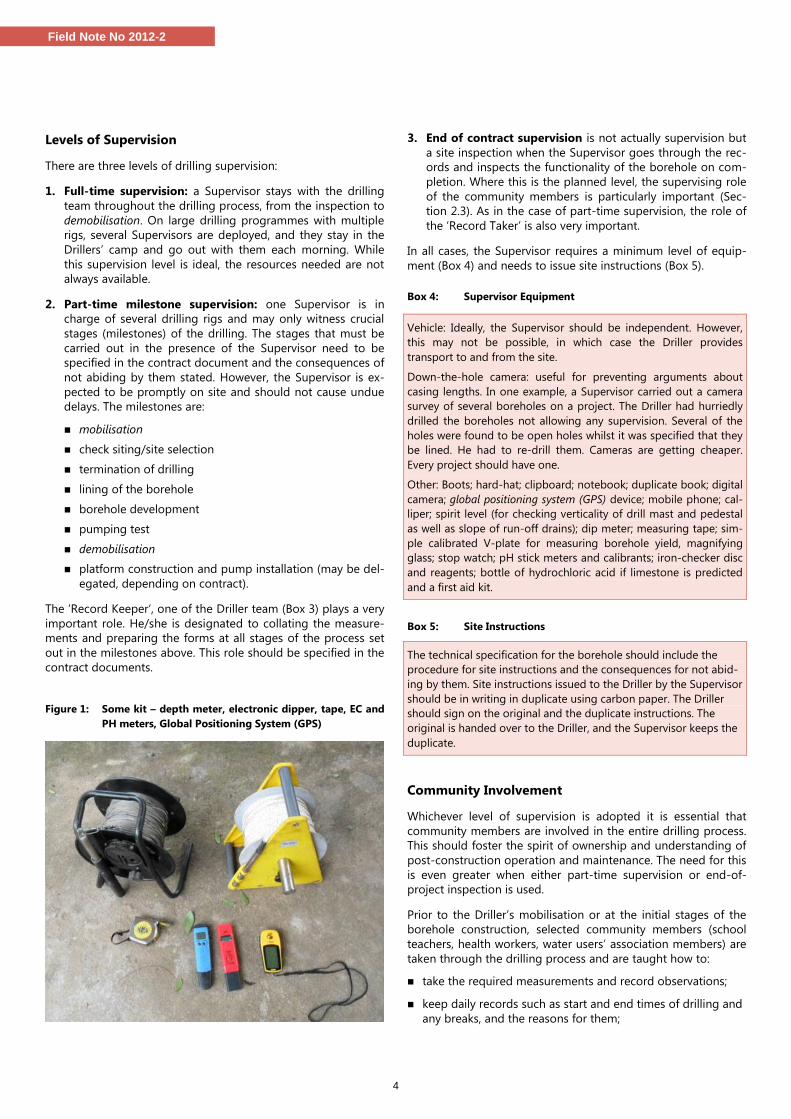
Figure 1: Some kit – depth meter, electronic dipper, tape, EC and
PH meters, Global Positioning System (GPS)
3. End of contract supervision is not actually supervision but
a site inspection when the Supervisor goes through the rec-
ords and inspects the functionality of the borehole on com-
pletion. Where this is the planned level, the supervising role
of the community members is particularly important (Sec-
tion 2.3). As in the case of part-time supervision, the role of
the ‘Record Taker’ is also very important.
In all cases, the Supervisor requires a minimum level of equip-
ment (Box 4) and needs to issue site instructions (Box 5).
Box 4: Supervisor Equipment
Vehicle: Ideally, the Supervisor should be independent. However,
this may not be possible, in which case the Driller provides
transport to and from the site.
Down-the-hole camera: useful for preventing arguments about
casing lengths. In one example, a Supervisor carried out a camera
survey of several boreholes on a project. The Driller had hurriedly
drilled the boreholes not allowing any supervision. Several of the
holes were found to be open holes whilst it was specified that they
be lined. He had to re-drill them. Cameras are getting cheaper.
Every project should have one.
Other: Boots; hard-hat; clipboard; notebook; duplicate book; digital
camera; global positioning system (GPS) device; mobile phone; cal-
liper; spirit level (for checking verticality of drill mast and pedestal
as well as slope of run-off drains); dip meter; measuring tape; sim-
ple calibrated V-plate for measuring borehole yield, magnifying
glass; stop watch; pH stick meters and calibrants; iron-checker disc
and reagents; bottle of hydrochloric acid if limestone is predicted
and a first aid kit.
Box 5: Site Instructions
The technical specification for the borehole should include the
procedure for site instructions and the consequences for not abid-
ing by them. Site instructions issued to the Driller by the Supervisor
should be in writing in duplicate using carbon paper. The Driller
should sign on the original and the duplicate instructions. The
original is handed over to the Driller, and the Supervisor keeps the
duplicate.
Community Involvement
Whichever level of supervision is adopted it is essential that
community members are involved in the entire drilling process.
This should foster the spirit of ownership and understanding of
post-construction operation and maintenance. The need for this
is even greater when either part-time supervision or end-of-
project inspection is used.
Prior to the Driller’s mobilisation or at the initial stages of the
borehole construction, selected community members (school
teachers, health workers, water users’ association members) are
taken through the drilling process and are taught how to:
take the required measurements and record observations;
keep daily records such as start and end times of drilling and
any breaks, and the reasons for them;
5
Field Note No 2012-2
determine depth of drilling by counting the number of drill
pipes lowered down;
record depth and time of the first water strike and other
strikes when drilling with air;
count and record the length and number of casings and
screens installed;
count the number of bags of cement used;
observe the installation of gravel and the sanitary seal, test
pumping and whether borehole chlorination is undertaken.
From the information provided by the community supervision,
the Supervisor can build an accurate account of the drilling pro-
gress which he/she can cross-check with the driller’s daily log.
What can realistically be expected of the community will de-
pend on their level of literacy and numeracy, too. It should also
be clear that community involvement can never replace an ex-
perienced supervisor.
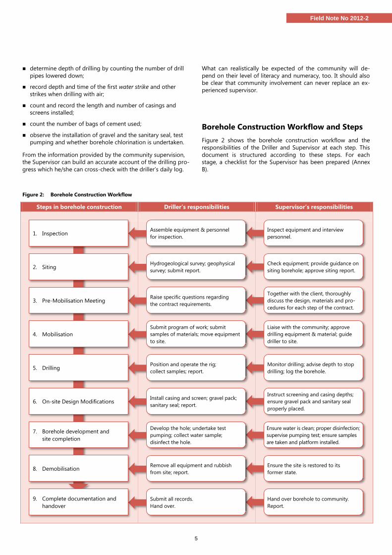
Borehole Construction Workflow and Steps
Figure 2 shows the borehole construction workflow and the
responsibilities of the Driller and Supervisor at each step. This
document is structured according to these steps. For each
stage, a checklist for the Supervisor has been prepared (Annex
B).
Figure 2: Borehole Construction Workflow
Steps in borehole construction Driller’s responsibilities Supervisor’s responsibilities
Ensure the site is restored to its
former state.
Hand over borehole to community.
Report.
Check equipment; provide guidance on
siting borehole; approve siting report.
Together with the client, thoroughly
discuss the design, materials and pro-
cedures for each step of the contract.
Liaise with the community; approve
drilling equipment & material; guide
driller to site.
Monitor drilling; advise depth to stop
drilling; log the borehole.
Instruct screening and casing depths;
ensure gravel pack and sanitary seal
properly placed.
Ensure water is clean; proper disinfection;
supervise pumping test; ensure samples
are taken and platform installed.
Inspect equipment and interview
personnel.
Assemble equipment & personnel
for inspection.
Hydrogeological survey; geophysical
survey; submit report.
Raise specific questions regarding
the contract requirements.
Submit program of work; submit
samples of materials; move equipment
to site.
Position and operate the rig;
collect samples; report.
Install casing and screen; gravel pack;
sanitary seal; report.
Develop the hole; undertake test
pumping; collect water sample;
disinfect the hole.
Remove all equipment and rubbish
from site; report.
Submit all records.
Hand over.
1. Inspection
2. Siting
3. Pre-Mobilisation Meeting
4. Mobilisation
5. Drilling
6. On-site Design Modifications
7. Borehole development and
site completion
8. Demobilisation
9. Complete documentation and
handover
6
Field Note No 2012-2
Step 1: Inspection
Aim: To verify the capabilities of the Driller BEFORE a
contract is signed.
A pre-qualification inspection of equipment and personnel may
be carried out as a pre-requisite for eligibility to tender, or as part
of the tender process. This may be undertaken by the client, or a
Supervisor may be engaged for this. It is essential to agree a date
with the prospective Drillers. Minimum requirements vary from
country to country, but Table 1 provides a list of essential equip-
ment and personnel the Driller should have for a contract pack-
age of 10 boreholes from Nigeria. Supervision Checklist 1 (Annex
B) shows the main aspects for inspection.
Where the Driller is required to carry out the geophysical survey
for the siting of the boreholes, his capability for such surveys has
to be determined. If the Driller proposes to employ a consultant
to carry out the siting, the availability of the consultant should be
confirmed and the equipment inspected and tested. The Driller’s
personnel or consultant should be a qualified hydrogeologist or
geophysicist. Depending on the specification for the siting, the
Driller should have a resistivity and electromagnetic meter, a
global positioning system (GPS) and appropriate software for data
interpretation. The sources of remote sensing tools, maps and
existing borehole data should be confirmed.
When the Driller has been selected and the contract awarded,
prior to mobilisation, the Driller should be asked to confirm the
availability of the approved items of equipment
Table 1: Example of basic equipment and personnel required for
a project of 10 boreholes
Type of Equipment Personnel
1 drilling rig 1 drilling manager
1 compressor 1 hydrogeologist
1 mud pump 1 rig operator
1 water tanker 1 driver
1 support truck 1 mechanic
Adequate lengths of drill pipes to drill the
deepest hole
3 rig assistants
Drill bits of the right diameter
Casing, gravel and filter pack, drilling mud
Step 2: Borehole siting
Aim: To ensure that the borehole is drilled in the right
place so that it has water that is accessible to
users and protected from pollution.
The Supervisor should refer to RWSN Publication 2010-5 Siting
of Drilled Water Wells: A Guide for Project Managers, which pro-
vides details of the procedure for borehole siting. Checklist 2
(Annex B) highlights the areas that will require particular atten-
tion from the Supervisor.
Site Survey: A survey of the community or project area should
have been carried out before the commencement of the project
and the estimated drilling depth in the Bill of Quantities based
on the depth indicated by the siting survey. The potential bore-
hole sites should be marked and shown to the Community.
Some communities have areas of cultural and religious values or
sacred ground which should be avoided. The Drillers are re-
sponsible for siting the borehole if the contract does not pay for
dry wells, the so-called “no water no pay” approach, in which
case they should follow steps 1 to 3 in Siting of Drilled Water
Wells (Figure 3).
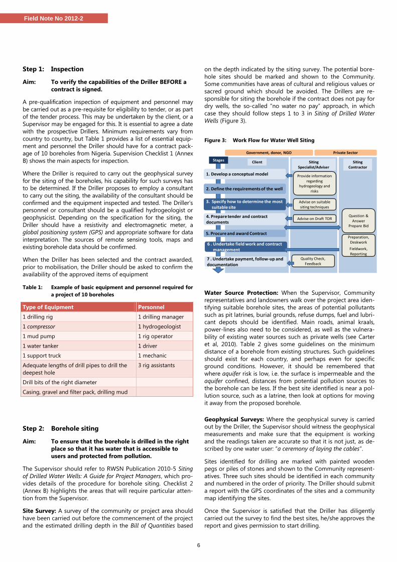
Figure 3: Work Flow for Water Well Siting
Water Source Protection: When the Supervisor, Community
representatives and landowners walk over the project area iden-
tifying suitable borehole sites, the areas of potential pollutants
such as pit latrines, burial grounds, refuse dumps, fuel and lubri-
cant depots should be identified. Main roads, animal kraals,
power-lines also need to be considered, as well as the vulnera-
bility of existing water sources such as private wells (see Carter
et al, 2010). Table 2 gives some guidelines on the minimum
distance of a borehole from existing structures. Such guidelines
should exist for each country, and perhaps even for specific
ground conditions. However, it should be remembered that
where aquifer risk is low, i.e. the surface is impermeable and the
aquifer confined, distances from potential pollution sources to
the borehole can be less. If the best site identified is near a pol-
lution source, such as a latrine, then look at options for moving
it away from the proposed borehole.
Geophysical Surveys: Where the geophysical survey is carried
out by the Driller, the Supervisor should witness the geophysical
measurements and make sure that the equipment is working
and the readings taken are accurate so that it is not just, as de-
scribed by one water user: “a ceremony of laying the cables”.
Sites identified for drilling are marked with painted wooden
pegs or piles of stones and shown to the Community represent-
atives. Three such sites should be identified in each community
and numbered in the order of priority. The Driller should submit
a report with the GPS coordinates of the sites and a community
map identifying the sites.
Once the Supervisor is satisfied that the Driller has diligently
carried out the survey to find the best sites, he/she approves the
report and gives permission to start drilling.
Siting Specialist/Adviser
Siting Contractor
Government, donor, NGO Private Sector
Client
Provide information regarding
hydrogeology and risks
Question &Answer
Prepare Bid
Preparation, Deskwork
Fieldwork, Reporting
Quality Check, Feedback
Stages
3. Specify how to determine the most suitable site
1. Develop a conceptual model
2. Define the requirements of the well
Advise on suitable siting techniques
4. Prepare tender and contract documents
6 . Undertake field work and contract management
Advise on Draft TOR
5. Procure and award Contract
7 . Undertake payment, follow-up and documentation
7
Field Note No 2012-2
Box 6: What happens if a suitable site for a borehole cannot be
found?
A perfect site would have favourable hydrogeology, no nearby
pollution threats, available land, and good access for the Drillers
and water users. However, this often does not happen, and if no
acceptable site can be found, then other sources of water will have
to be sought by the Project Manager with the Community.
Table 2: Borehole distance from existing structures (adapted
from FGN/NWRI, 2010)
Existing structures Minimum distance (m) from borehole
Water supply boreholes 50
Hand-dug well 20
Other existing water wells 10
Septic tank/soak away 20
Streams, canals, irrigation ditches 20
Buildings 3
Approved solid waste dump and burial ground 1,000
Coastline not normally within 1,000 meters
Step 3: Pre-Mobilisation Meeting
Aim: To ensure that the Driller and Supervisor are fully
aware of their exact roles and responsibilities and
contract details.
Once the contract has been signed, and prior to mobilisation, a
meeting between the Client, Driller and Supervisor is essential.
At the meeting, all three parties go over the design, materials
and procedures for each step in the contract. Roles and respon-
sibilities need to be clarified in detail. This provides an oppor-
tunity for any ambiguity to be resolved and the contract
amended as necessary.
However, many Drillers do not read the contract, but simply add
their prices into the Bill of Quantities. The pre-mobilisation
meeting ensures that everything set out in the contract is clari-
fied verbally, thus preventing conflicts while on site. Without
this, there is always a danger that the wrong equipment or infe-
rior materials will be taken to site, and the Supervisor compro-
mised due to time-pressure.
Step 4: Mobilisation
Aim: To take the drilling project from contract signing
to deployment of the drilling crew on site
Checklist 3 (Annex B) sets out the main aspects of this step,
starting with liaison and ending up on site. Mobilisation in-
cludes the following activities:
1. Contract: All borehole projects and supervision are based on a
contract agreement. Once the contract has been signed, and
pre-mobilisation meeting held (Step 3), the mobilisation phase
starts. Procurement and contract management aspects are cov-
ered in Adekile (2012).
2. Programme of works: The Supervisor should discuss the
technical specifications and drilling procedure with the Drill-
er, and discuss and agree the target depths. Then the Super-
visor should ask the Driller to submit a programme of works.
An example is shown in Table 3.
Table 3: Example of Program of Completing Drilling Works for a
5-borehole package
Description Weeks
1 2 3 4 5 6 7 8 9 10
Mobilisation
Borehole siting
Drilling, lining & development
Communities 1 & 2
Communities 3 & 4
Community 5
Pumping test & water quality analysis
Pad construction
Pump installation
Demobilisation
3. Community liaison: It is essential that, before the Driller
arrives on site, the Supervisor or Project Manager has had
several discussions with the Community about the project
and details of the drilling process and their expected obliga-
tions and contributions with the main contact persons or
Community representatives. The Driller’s representative
should meet with the Community and agree a start date.
4. Equipment check: The equipment that is to be used by the
Driller should be checked to make sure that it is all in work-
ing condition, and the same as, or equivalent to, what was
examined in the inspection step.
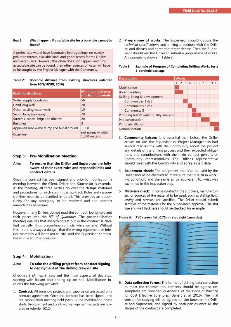
5. Materials check: In some contracts, the suppliers, manufactur-
ers, or sources of the material to be used, such as drilling fluid,
casing and screens, are specified. The Driller should submit
samples of the materials for the Supervisor’s approval. The slot
size and wall thickness should be checked, for example.
Figure 4: PVC screen (left 0.75mm slot, right 1mm slot)
6. Data collection forms: The format of drilling data collection
to meet the contract requirements should be agreed on.
Templates are provided in Annex E of the Code of Practice
for Cost Effective Boreholes (Danert et al, 2010). The final
version for copying will be agreed on site between the Drill-
er and Supervisor, and signed by both parties once all the
stages of the contract are completed.
8
Field Note No 2012-2
7. Project filing system: Most of the data could be stored
electronically, but hard copies are required for field use. A
file (in duplicate) should be opened for every community
and all records and data for the community stored in the
file. Checklists for all stages of borehole construction (Annex
B) are printed inside the flap of the folder and ticked as con-
struction progresses. The original is kept in the office and
the duplicate in the Drill Camp or site office.
8. Drill camp layout: On large projects where a Drill Camp is
set up, the Driller should submit a drawing of the camp lay-
out for approval. The main consideration in approving the
plan is safety and sanitation: inflammable items should be
kept away from likely sources of heat and fire; potential con-
taminants from water-supply sources and cooking areas;
and PVC casing and screens are protected from direct sun-
light, which makes them brittle. Where the project covers a
large area, Satellite Fly Camps may be needed in the more
remote parts to reduce the travelling time to a cluster of
borehole sites. The same criteria as for the approval of the
Drill Camp plan apply.
Once all the above have been completed and approved, the
Driller and the Supervisor are ready to move to site.
Step 5: Drilling
Aim: To ensure a high-quality borehole is drilled in a
way that is safe and well-documented.
Checklist 4 (Annex B) should be used once the Driller has
reached the project site. The following aspects are critical:
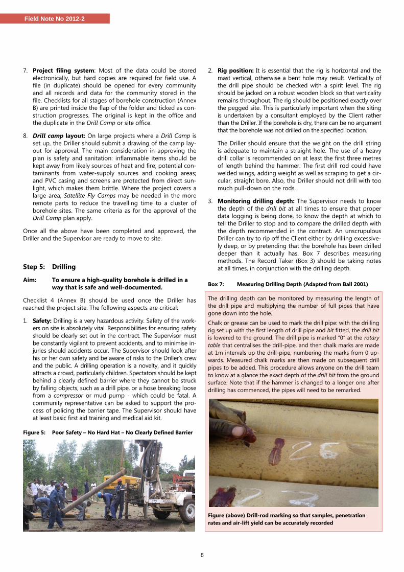
1. Safety: Drilling is a very hazardous activity. Safety of the work-
ers on site is absolutely vital. Responsibilities for ensuring safety
should be clearly set out in the contract. The Supervisor must
be constantly vigilant to prevent accidents, and to minimise in-
juries should accidents occur. The Supervisor should look after
his or her own safety and be aware of risks to the Driller’s crew
and the public. A drilling operation is a novelty, and it quickly
attracts a crowd, particularly children. Spectators should be kept
behind a clearly defined barrier where they cannot be struck
by falling objects, such as a drill pipe, or a hose breaking loose
from a compressor or mud pump - which could be fatal. A
community representative can be asked to support the pro-
cess of policing the barrier tape. The Supervisor should have
at least basic first aid training and medical aid kit.
Figure 5: Poor Safety – No Hard Hat – No Clearly Defined Barrier
2. Rig position: It is essential that the rig is horizontal and the
mast vertical, otherwise a bent hole may result. Verticality of
the drill pipe should be checked with a spirit level. The rig
should be jacked on a robust wooden block so that verticality
remains throughout. The rig should be positioned exactly over
the pegged site. This is particularly important when the siting
is undertaken by a consultant employed by the Client rather
than the Driller. If the borehole is dry, there can be no argument
that the borehole was not drilled on the specified location.
The Driller should ensure that the weight on the drill string
is adequate to maintain a straight hole. The use of a heavy
drill collar is recommended on at least the first three metres
of length behind the hammer. The first drill rod could have
welded wings, adding weight as well as scraping to get a cir-
cular, straight bore. Also, the Driller should not drill with too
much pull-down on the rods.
3. Monitoring drilling depth: The Supervisor needs to know
the depth of the drill bit at all times to ensure that proper
data logging is being done, to know the depth at which to
tell the Driller to stop and to compare the drilled depth with
the depth recommended in the contract. An unscrupulous
Driller can try to rip off the Client either by drilling excessive-
ly deep, or by pretending that the borehole has been drilled
deeper than it actually has. Box 7 describes measuring
methods. The Record Taker (Box 3) should be taking notes
at all times, in conjunction with the drilling depth.
Box 7: Measuring Drilling Depth (Adapted from Ball 2001)
The drilling depth can be monitored by measuring the length of
the drill pipe and multiplying the number of full pipes that have
gone down into the hole.
Chalk or grease can be used to mark the drill pipe: with the drilling
rig set up with the first length of drill pipe and bit fitted, the drill bit
is lowered to the ground. The drill pipe is marked “0” at the rotary
table that centralises the drill-pipe, and then chalk marks are made
at 1m intervals up the drill-pipe, numbering the marks from 0 up-
wards. Measured chalk marks are then made on subsequent drill
pipes to be added. This procedure allows anyone on the drill team
to know at a glance the exact depth of the drill bit from the ground
surface. Note that if the hammer is changed to a longer one after
drilling has commenced, the pipes will need to be remarked.
Figure (above) Drill-rod marking so that samples, penetration
rates and air-lift yield can be accurately recorded
9
Field Note No 2012-2
4. Penetration rate: This is the time taken to drill a particular
interval. A fast penetration rate can indicate an aquifer, alt-
hough this is not always the case. Less porous strata, such as
fresh granites, are often slower to drill through.
5. Drilling fluids & air-lift yield: Drilling fluids are used to
remove cuttings from the borehole and to stop the hole col-
lapsing during drilling. The type of fluid should match the
drilling method:
Down-the-hole-hammer: compressed air; water and air;
or foam;
Rotary drilling: drilling mud (water + additive). Be aware
that bentonite clay is commonly used but is outlawed in
some countries because it can do permanent damage to
the aquifer. Biodegradable polymers should be used;
Percussion drilling: fluids generally not used;
Manual drilling (percussion, auger, sludging, jetting): water.
Monitoring the drilling fluid colour and viscosity is the re-
sponsibility of the Driller. Viscosity is checked by measuring
the flow rate of the drilling fluid through a Marsh Funnel.
The Supervisor should ensure the Driller has a Marsh Fun-
nel and it is properly used. In the case of air-percussion
drilling, the air-lift yield should be measured using a V-
plate or pipe/container. All observations and measurements
are recorded every metre, using the marks on the drill pipe
as a guide.
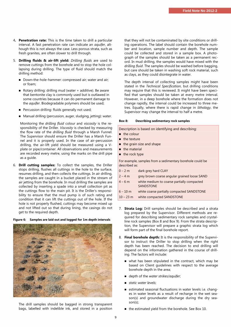
6. Drill cutting samples: To collect the samples, the Driller
stops drilling, flushes all cuttings in the hole to the surface,
resumes drilling, and then collects the cuttings. In air drilling,
the samples are caught in a bucket placed in the stream of
air jetting from the borehole. In mud drilling the samples are
collected by inserting a spade into a small collection pit as
the cuttings flow to the main pit. It is the Driller’s responsi-
bility to ensure that the mud pump is of such rating and
condition that it can lift the cuttings out of the hole. If the
hole is not properly flushed, cuttings may become mixed up
and not lifted out so that during lining, the casings do not
get to the required depth.
Figure 6: Samples are laid out and logged for 1m depth intervals
The drill samples should be bagged in strong transparent
bags, labelled with indelible ink, and stored in a position
that they will not be contaminated by site conditions or drill-
ing operations. The label should contain the borehole num-
ber and location, sample number and depth. The sample
could be collected and stored in a sample box. A photo-
graph of the samples should be taken as a permanent rec-
ord. In mud drilling, the samples would have mixed with the
drilling fluid. The samples should be washed before bagging,
but care should be taken in washing soft rock material, such
as clays, as they could disintegrate in water.
The depth interval of collecting samples might have been
stated in the Technical Specification, but drilling conditions
may require that this is reviewed. It might have been speci-
fied that samples should be taken at every metre interval.
However, in a deep borehole where the formation does not
change rapidly, the interval could be increased to three me-
tres. Equally, where there is rapid change in lithology, the
Supervisor may change the interval to half a metre.
Box 8: Describing sedimentary rock samples
Description is based on identifying and describing:
the colour
the texture
the grain size and shape
the material
the rock type
For example, samples from a sedimentary borehole could be
described as:
0 – 2 m dark grey hard CLAY
2 – 4 m grey brown coarse angular grained loose SAND
4 – 6 m white medium to coarse partially compacted
SANDSTONE
6 – 10 m white coarse partially compacted SANDSTONE
10 – 23 m white compacted SANDSTONE
7. Strata Log: Drill samples should be described and a strata
log prepared by the Supervisor. Different methods are re-
quired for describing sedimentary rock samples and crystal-
line rock samples (Box 8 and Box 9). From the strata descrip-
tion, the Supervisor will prepare a graphic strata log which
will form part of the final borehole report.
8. Final borehole depth: It is the responsibility of the Supervi-
sor to instruct the Driller to stop drilling when the right
depth has been reached. The decision to end drilling will
depend on the information gathered in the course of drill-
ing. The factors will include:
what has been stipulated in the contract, which may be
based on Client guidelines with respect to the average
borehole depth in the area;
depth of the water strikes/aquifer;
static water levels;
estimated seasonal fluctuations in water levels i.e. chang-
es in water levels as a result of recharge in the wet sea-
son(s) and groundwater discharge during the dry sea-
son(s);
the estimated yield from the borehole. See Box 10.

10
Field Note No 2012-2
The typical signs for adequate yield and drilling depth vary
with the type of formation and the drilling method. In the
case of a yield which is obviously good, in a well that is to be
installed with a handpump the final borehole depth should
be at least 5 metres into the aquifer. It needs to allow for
proper installation of the pump. It also should allow for 3 to
6 metres of sump (blank casing) below the screen as a sand
trap.
However, if the yield is not clearly so good, continue to drill
to the next strike horizon, until the yield is sufficient. The
yield increments should be monitored with the V-plate. A
6m sump may be suitable where sand and silt are a prob-
lem. In cases where there is fine saprolite in the upper sec-
tions, these should be cased off to prevent silt from entering
and filling the sump.
Box 9: Description and classification of crystalline rocks based
on grades of weathering and dominant minerals
Grade Classifier Typical Characteristic
I Fresh Unchanged from original state
II Slightly
weathered
Slight discolouration, slight weakening
and dislocation
III Moderately
weathered
Considerably weakened, penetrative
discolouration
Large pieces cannot be broken by hand
IV Highly
weathered
Large pieces can be broken by hand
Does not readily disaggregate (slake)
when dry sample immersed in water
V Completely
weathered
Considerably weakened
Slakes
Original texture apparent
VI Residual soil Soil derived in situ weathering but
retaining none of the original texture or
fabric
For example, the log from a granitic terrain might read as follows:
0 – 6 m orange brown silty CLAY
6 – 16 m grey brown clayey fine SAND
16 - 23 m biotite granite GNEISS IV-III+
23 - 30 m biotite granite GNEISS III+
30 – 43 m biotite granite GNEISS I
9. Drill Report: The data from the drilling should be recorded
both for the final design and as a reference for future bore-
hole projects. The Driller needs to keep a daily drilling log
which should be signed by the rig operator and the Supervi-
sor at the end of each day. The Supervisor should insist that
this is done - as Drillers often consider this an unnecessary
intrusion into their work. The Supervisor should keep the
record of the drilling activities and all measurements in a
field note book. The most important data will go into the
Casing and Well Completion Form (Appendix E3, Code of
Practice for Cost Effective Boreholes), which will be collated,
filed or bound together as part of the final project report
and deposited with the appropriate office for future refer-
ence. Even data from dry or aborted holes needs to be rec-
orded.
Box 10: Indications of adequate yield and depth
Crystalline basement geology: Geophysical survey data should
indicate the probable depth to fresh rock. On the basement com-
plex of West Africa, this is usually not more than 60m because the
regolith is rarely more than 30m deep and most joints close up by
50m depth. In East and Southern Africa the regolith may be as
thick as 100m.
If the borehole is drilled with air, then water strikes will be obvious
because the water shoots out of the hole. The yield of the borehole
can be estimated as drilling progresses by making a small depression
around the hole. The water blown out of the hole is channelled into
a pipe. The yield is estimated by measuring the time it takes to fill a
bucket of known volume, giving the yield in litres per second (l/s).
A handpump demand is about 0.3 l/s. If the yield is adequate for the
demand, then the static water level is measured. If the borehole is
drilled in the wet season, a depth allowance is added to cover for
seasonal fluctuation in water levels. A further allowance is made for
the drawdown caused by pumping. Thus, a borehole with a static
water level of 10m might need an allowance of 15m for seasonal
fluctuation and drawdown. In this case it would be 30m depth well.
The depth at which fresh rock is encountered may be a signal to
stop drilling but if this is at shallow depth, not indicated in the
geophysical survey it is necessary to continue drilling for another 5
to 10m to rule out the possibility of a boulder or spheroidal weath-
ering. Fresh rock in hammer drilling comes out as fine or powdery
material, dark or light coloured depending on the parent material.
Some consolidated sediments (sandstones, mudstones, shales):
Can be highly compacted, hard and have to be drilled with down-
the-hole hammer and air. Deciding at what depth to stop follows
the same observations as in crystalline rock drilling. Some consoli-
dated sediments are not so compacted and will follow the same
method as with unconsolidated rocks.
Unconsolidated formations (gravels, sands): It is not possible to
see the water strike as in air drilling because the borehole is drilled
with a drilling mud. The yield cannot be estimated until the bore-
hole is lined and cleaned. The final borehole depth will depend on
the pre-drilling hydrogeological information from existing bore-
holes and, sometimes, geophysical logging and the lithological types
encountered during drilling. Close monitoring of the entire drilling
process is required to find the water-bearing layers. Drilling can stop
when the borehole reaches a continuously thick band of sand or
fissured limestone below the zone of permanent saturation, at a
depth correlating with the aquifers screened in other nearby bore-
holes. It is best to penetrate as much of the aquifer as possible.
In unconsolidated sediments, careful observation of the drilling
process will reveal one or more of the following signs indicating
that a good water-bearing layer has been reached:
sampling of drill cuttings shows a layer of sand or gravel has
been reached (this needs careful sampling of drill cuttings)
increase in the penetration rate
bouncing of the drill string caused by a bed of gravels
loss of viscosity in the drilling fluid (measured with a marsh
funnel)
sudden change of colour of the drilling fluid
noticeable drop in the level of the drilling fluid
drilling fluid temperature may drop due to groundwater
inflow.
11
Field Note No 2012-2
Step 6: On-site Design Modifications
Aim: To ensure that the finished borehole uses the
aquifer efficiently, gives a long working life and
low capital, maintenance and operation costs.
The Code of Practice for Cost Effective Boreholes (Danert et al,
2010) provides illustrations of different borehole designs. The
provisional design should precede the signing of the contract,
because the design gives rise to the specification. The specifica-
tion informs the Driller what to bring to site. Any design work
on site involves modifications to, or finalisation of, the design.
The Supervisor is responsible for on-site design modifications.
Every borehole design is unique because it has to be adapted to
the local geology, which cannot be predicted with absolute cer-
tainty. Borehole design involves selecting the appropriate di-
mensions and materials of the borehole, i.e. depth, casing and
screen type and diameter, depth intervals of installation, and
gravel pack zone. Borehole design factors are set out in Check-
list 5 and described in further detail below. Most of the parame-
ters listed above would have already been taken into considera-
tion when writing the technical specifications of the borehole,
but the information gathered in the course of drilling will steer
the final design.
1. Depth: Taken from the Drill Report;
2. Formation: What type of aquifer is the borehole taking wa-
ter from? Use local geological expertise and mapping where
possible, but in general the three aquifer types are: Base-
ment Complex; Consolidated sediments; and Unconsolidated
sediments;
3. Yield: A borehole only needs to be drilled to a depth where
the required yield can be sustained without contamination
from surface water. Table 4 gives the ranges of yields from
different formations. Selection of the other parameters, such
as the borehole diameter and lining, should be geared to-
wards meeting the required yield.
Table 4: Ranges of yields from various aquifers
Aquifer type Rock types Yield l/s
Consolidated sediments Sandstones, mudstones 0.1 – 4
Unconsolidated sediments Sands, gravels >4
Basement complex* Weathered granites 0.1 – 1
* Basement complex is also divided into (a) Saprolite (which frequently
suffers from low yield and is prone to silt influx): (b) Saprock (frequently
has a high yield) and (c) Bedrock (high yield potential where fractured).
4. Drilled borehole diameter: The drilled diameter of the
borehole needs to be large enough so that pump, casing,
screens, gravel pack and sanitary seal can all fit without
snagging. For handpump-fitted boreholes there are different
schools of thought with respect to diameter, with some fa-
vouring smaller diameters, such as 6” to 6.5” and others ar-
guing that this is inadequate to enable gravel packing to be
properly installed without bridging. Anscombe (2012), a
Driller with years of experience in southern Africa, argues
that the reality is that most Drillers simply do not use a
tremie pipe when installing gravel pack, with the result that
the gravel pack is not properly installed. He thus argues that
wells need to be drilled at an 8” diameter. This view has cost
implications.
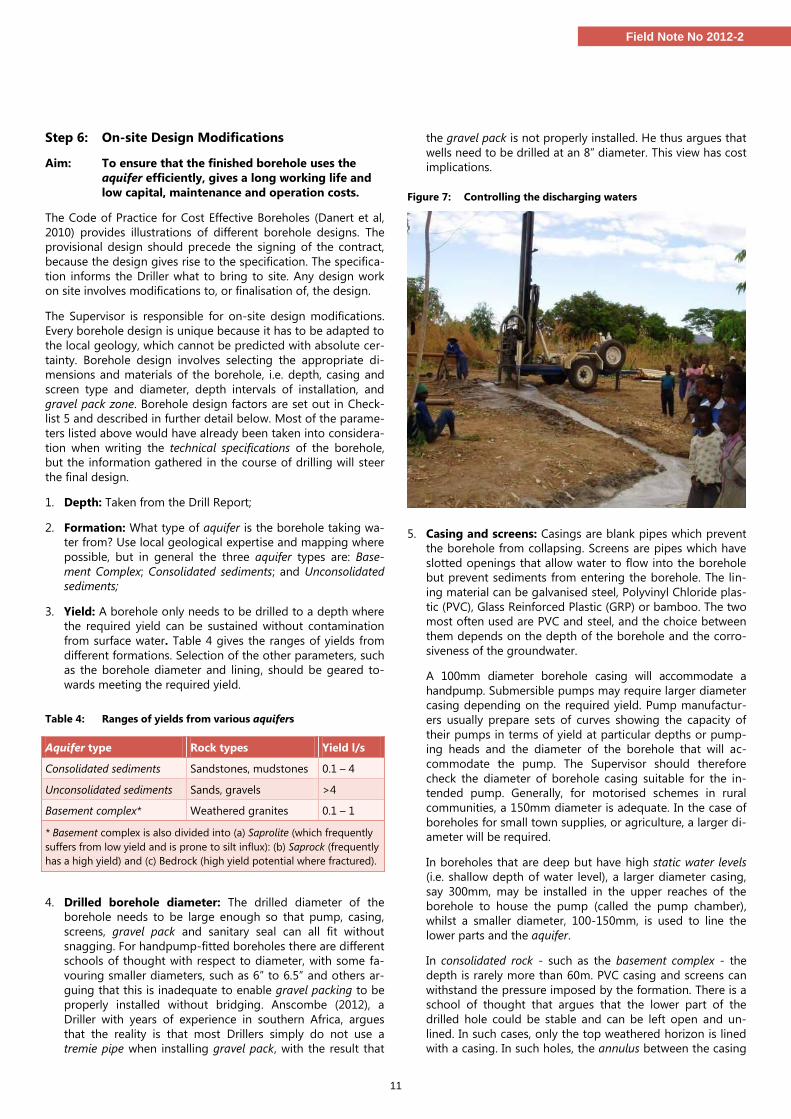
Figure 7: Controlling the discharging waters
5. Casing and screens: Casings are blank pipes which prevent
the borehole from collapsing. Screens are pipes which have
slotted openings that allow water to flow into the borehole
but prevent sediments from entering the borehole. The lin-
ing material can be galvanised steel, Polyvinyl Chloride plas-
tic (PVC), Glass Reinforced Plastic (GRP) or bamboo. The two
most often used are PVC and steel, and the choice between
them depends on the depth of the borehole and the corro-
siveness of the groundwater.
A 100mm diameter borehole casing will accommodate a
handpump. Submersible pumps may require larger diameter
casing depending on the required yield. Pump manufactur-
ers usually prepare sets of curves showing the capacity of
their pumps in terms of yield at particular depths or pump-
ing heads and the diameter of the borehole that will ac-
commodate the pump. The Supervisor should therefore
check the diameter of borehole casing suitable for the in-
tended pump. Generally, for motorised schemes in rural
communities, a 150mm diameter is adequate. In the case of
boreholes for small town supplies, or agriculture, a larger di-
ameter will be required.
In boreholes that are deep but have high static water levels
(i.e. shallow depth of water level), a larger diameter casing,
say 300mm, may be installed in the upper reaches of the
borehole to house the pump (called the pump chamber),
whilst a smaller diameter, 100-150mm, is used to line the
lower parts and the aquifer.
In consolidated rock - such as the basement complex - the
depth is rarely more than 60m. PVC casing and screens can
withstand the pressure imposed by the formation. There is a
school of thought that argues that the lower part of the
drilled hole could be stable and can be left open and un-
lined. In such cases, only the top weathered horizon is lined
with a casing. In such holes, the annulus between the casing
12
Field Note No 2012-2
and the drilled hole should be grouted. However, it has been
argued that these holes are not always sustainable, with
some prone to siltation.
In unconsolidated formations, the entire borehole is lined to
prevent the borehole from collapsing. Where the aquifer is
more than 100m deep, the pressure exerted by the water and
the rock formation is great, and steel casing and screen
should be installed. In deep aquifers with slightly acidic water,
Glass Reinforced Plastic may be considered as mild steel could
corrode..
The Supervisor should ensure that the casings and screens
supplied are new and conform to the specification. If in
doubt, the diameter and the wall thickness should be
checked with callipers. The Driller should provide a sample
of the pipe cut in half, and the measurement taken in the
middle. Measuring the thickness at the threaded end will not
give the accurate figure. Table 5 gives the dimensions of
casings, wall thickness and possible depths of installation
from a pipe manufacturer.
It should be noted that drill pipes, casings, screens and other
lengths are not always standard. Sometimes they are cut
and re-threaded. Often, 3m “standard lengths” are actually
2.95m, or some other length.
Table 5: PVC casing and screen dimensions
(Source: manufacturer Boode b.v Netherlands).
Indication of installation depth m*
Outside x inside diameter in mm
Wall thickness in mm
50 – 75 110 x 103.4 (3½’’) 3.3
75 – 100 110 x 101.6 (3½”) 4.2
200 – 300 113 x 96.6 (4”) 8.2
50 – 75 125 x 117.6 (4½”) 3.7
75 – 100 125 x 115.4 (4½”) 4.8
* Depths of installations mentioned are based on practical experience
and may vary with ground condition.
6. Screens: are installed in the aquifer horizon. A borehole
screen is a filtering device that serves as the intake portion
of boreholes constructed in unconsolidated and semi-
consolidated aquifers. The screen permits water to enter the
borehole from the aquifer, prevents sediments from entering
the borehole and serves to support the aquifer material. In-
creasing borehole diameter does not have much impact on
water flow into the borehole, but increasing the screen
length significantly increases the yield. Therefore, as much of
the aquifer as cost permits should be screened. There is not
much difference in the prices of PVC casing and screen, but
stainless steel screens are very expensive and should be
used sparingly.
7. Screen slot size: The total open area of the screen governs
the amount of water that flows into the hole. Slot sizes are
not a big issue with handpumps as the required amount of
water is relatively small. It is enough to ensure that the aqui-
fer material will be retained by the selected screen slot size.
This can be checked by doing a sieve analysis of the aquifer
material, but a quick method is to rub a sample of the aqui-
fer material against the screen. An adequate slot size will al-
low the fines to pass through, whilst the coarse material re-
mains outside. It has been noted that in some southern Afri-
ca countries, locally available casing tends to be rather
coarse (1mm slot size). This will not always be adequate. If
the aquifer is laden with silt, and the slots allow it to pass
through, it can result in the wearing of pump seals, and ul-
timately in siltation of the well.
In motorised schemes where a high yield is required, a large
diameter screen may be installed as the total open area in-
creases. Water flows freely through a screen with a large in-
take area compared to one with limited open area. To pre-
vent turbulent flow into the borehole which could cause en-
crustation and lower the lifespan of the screen, the velocity
through the screen should not be more than 0.03 m/s. The
minimum open area in the screen to permit non-turbulent
flow can be calculated from the formula:
A = Q/30
where A is the open area in m2 and Q is the water flow in l/s
(Macdonald et al, 2005)
8. Installing casing and screen requires great care and atten-
tion as it is easy to install blank casing in the aquifer horizon.
Once the depth of the borehole and the depth interval for
screening are known, a sketch of the proposed assemblage of
casing and screen should be made. The casings and screens
should be laid out according to the sketch and measured in-
dividually, totalled and checked that they conform to the
sketch. They should be placed next to the drill collar ready to
go into the well. The Supervisor should take a photograph of
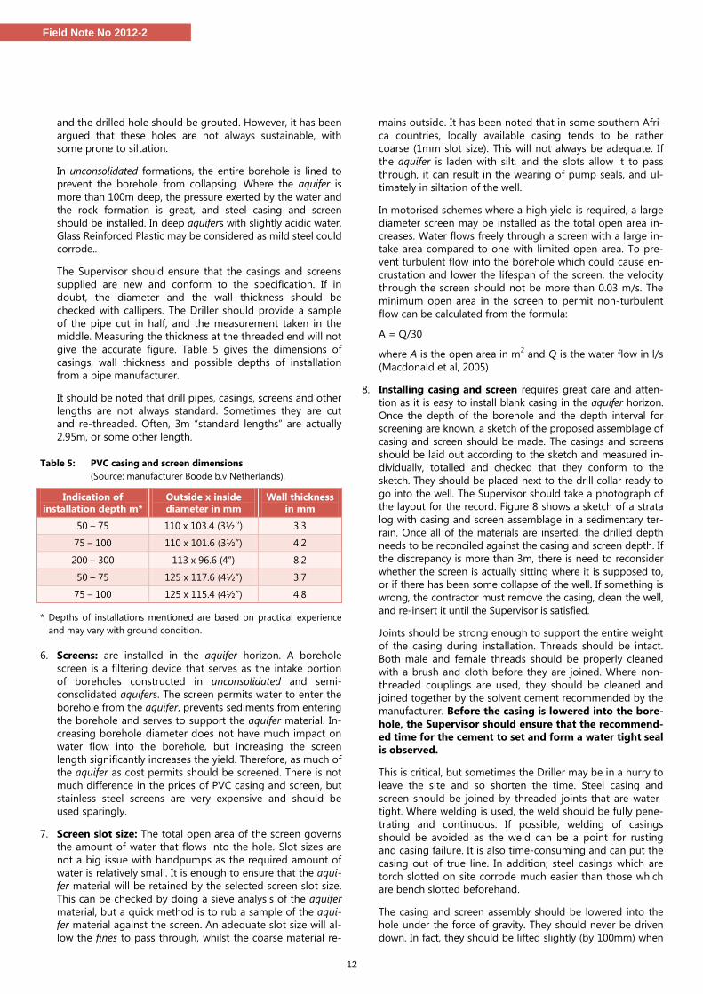
the layout for the record. Figure 8 shows a sketch of a strata
log with casing and screen assemblage in a sedimentary ter-
rain. Once all of the materials are inserted, the drilled depth
needs to be reconciled against the casing and screen depth. If
the discrepancy is more than 3m, there is need to reconsider
whether the screen is actually sitting where it is supposed to,
or if there has been some collapse of the well. If something is
wrong, the contractor must remove the casing, clean the well,
and re-insert it until the Supervisor is satisfied.
Joints should be strong enough to support the entire weight
of the casing during installation. Threads should be intact.
Both male and female threads should be properly cleaned
with a brush and cloth before they are joined. Where non-
threaded couplings are used, they should be cleaned and
joined together by the solvent cement recommended by the
manufacturer. Before the casing is lowered into the bore-
hole, the Supervisor should ensure that the recommend-
ed time for the cement to set and form a water tight seal
is observed.
This is critical, but sometimes the Driller may be in a hurry to
leave the site and so shorten the time. Steel casing and
screen should be joined by threaded joints that are water-
tight. Where welding is used, the weld should be fully pene-
trating and continuous. If possible, welding of casings
should be avoided as the weld can be a point for rusting
and casing failure. It is also time-consuming and can put the
casing out of true line. In addition, steel casings which are
torch slotted on site corrode much easier than those which
are bench slotted beforehand.
The casing and screen assembly should be lowered into the
hole under the force of gravity. They should never be driven
down. In fact, they should be lifted slightly (by 100mm) when
13
Field Note No 2012-2
they reach the bottom and held there while the gravel is in-
serted (see point 9). This ensures that they are straight in the
hole and not spiralled. In some cases, centralisers are used to
align the casing in the hole. A 3m length of sand trap should
be part of the well design when boreholes are cased to the
bottom and the bottom casing sealed with an end cap.
Figure 8: Casing and screen sketch in comparison to strata log
9. Gravel pack: is installed in the annular space between the
borehole screen and the wall of the drilled hole. Often, the
aquifer material is allowed to collapse against the screen,
and the fines are washed out during development. This ena-
bles natural development to take place. Where the aquifer
material is coarse and mobile, it is the preferred method.
However, where this is not possible, artificial gravel packing
is used. There are two types with different functions:
The formation stabiliser is coarse sand or river gravel in-
stalled in the hole to prevent the caving of formation ma-
terial and damage to the screen. The material should be
carefully chosen and sieved to make sure it is of uniform
size and bigger than the slot size of the screen and will
not flow into the borehole. It should not contain mica,
clay or laterite. Large pieces should be sieved out as they
can bridge in the annulus and prevent subsequent gravel
from reaching the bottom. Granite chippings should not
be used as gravel pack as they tend to be angular and
may contain mica or harmful material that leach into the
water. The material should be washed and carefully intro-
duced into the hole through a tremie pipe to avoid bridg-
ing. It should extend several meters above the screened
interval but stop at least 6m below ground surface.
A filter pack is installed around the screen in fine
grained unconsolidated formations where an appropriate
screen slot size cannot be found. The grain size of the fil-
ter pack material has to be selected in relation to that of
the formation material. It should be coarser than the aq-
uifer sand. The relationship, called the pack-aquifer ratio
(P.A. ratio), is calculated from the formula:
Pack Aquifer ratio = 50% size of gravel pack/50% size of
aquifer material
The ratio should be between 4 and 6. For the procedure
for sieve analysis and selection of appropriate filter mate-
rial the reader should consult Driscoll, 1986: 406-409.
It is essential that the casing, screen and gravel pack are
available on the site once drilling commences. Once the drill-
ing pipes are withdrawn, the hole has a potential to collapse.
Thus the casing and gravel pack need to be placed without
delay. Under no circumstances should this wait until the fol-
lowing morning. In the words of Anscombe (2012): “Rods out
– casing and gravel in – fast and efficient”.
10. Geotextiles: In some cases, geotextiles can be used to pre-
vent fine materials from entering the screen.
Step 7: Borehole development and site completion
Aim: To prepare the borehole for use and install the
pump and ancillary headworks and structures
Checklist 6 (Annex B) sets out the key aspects of borehole de-
velopment and site completion:
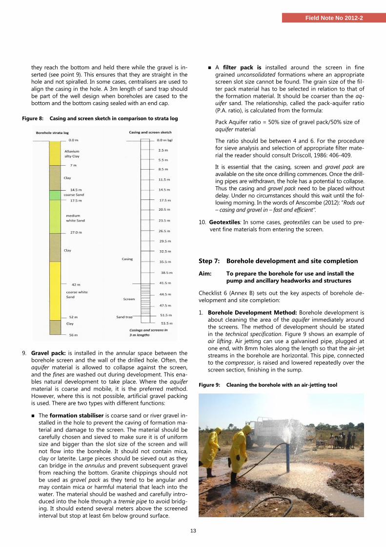
1. Borehole Development Method: Borehole development is
about cleaning the area of the aquifer immediately around
the screens. The method of development should be stated
in the technical specification. Figure 9 shows an example of
air lifting. Air jetting can use a galvanised pipe, plugged at
one end, with 8mm holes along the length so that the air-jet
streams in the borehole are horizontal. This pipe, connected
to the compressor, is raised and lowered repeatedly over the
screen section, finishing in the sump.
Figure 9: Cleaning the borehole with an air-jetting tool

14
Field Note No 2012-2
2. Borehole Development Success: The Supervisor’s duty is to
ensure that eventually, the water coming out from the bore-
hole is clear of mud and is sand free. Samples of the water
are collected in a clear container and checked to see that
there are no sediments collecting at the bottom of the con-
tainer. As part of this, the Supervisor needs to decide
whether a borehole should be accepted or declared abor-
tive. If the borehole is to be aborted, the Supervisor also
needs to determine whether the Driller should re-drill the
borehole at his own expense or not. This will depend on the
terms and conditions of the contract.
Although some contracts specify the duration of develop-
ment (the minimum number of hours that must be spent on
developing the hole), this actually depends on the time it
takes for the water to be clean. Development should contin-
ue until the Supervisor is satisfied that the water coming out
of the borehole is clean and sand free. Some boreholes clear
within a couple of hours, some may take days to several
weeks. Some only clear after several months of pumping.
The latter is likely if air-percussion drilling has been used in
very loose, clay-rich, silty, micaceous and saturated condi-
tions – in other words not the right drilling technique.
3. Sanitary seal: It is essential to prevent contamination of the
aquifer and to ensure that the users obtain safe, clean drink-
ing water. When the Supervisor is satisfied with the yield,
and development has settled the formation stabiliser or filter
pack, then the annulus of the borehole is back-filled with the
cuttings, or clayey soil, up to 6m below the ground surface.
A sanitary seal is placed in the top 6m to prevent surface
water which may be polluted from flowing down the bore-
hole annulus into the aquifer. The sanitary seal should be
cement slurry in the mixture of 25l of water to 50kg of neat
cement, or bentonite.
4. Pumping test provides the means to determine the likely
success of the borehole in terms of yield and drawdown. It
provides information on the properties of the aquifer and on
the borehole itself.
Two types of pumping test can be conducted. A constant-
discharge or aquifer test should always be carried out. This
gives information about the drawdown resulting from a spe-
cific pumping rate (usually a little greater than the design
discharge). The test data can also be interpreted in terms of
the aquifer properties. For a handpump, a 3- to 6-hour con-
stant discharge test is adequate. If the borehole is going to
serve a large population and a high yield is required, then a
longer test of say 24 to 72 hours, or even longer (up to 14
days) may be undertaken.
A constant discharge test provides information about the
aquifer in the vicinity of the well. The results of the constant
discharge pumping test enable the short term performance
of the well to be determined. However, it does not provide
any information about recharge, seasonal fluctuations or
long term performance. In other words, the pumping test
does not give information about the long-term (multi-year)
sustainable yield of the borehole. The long-term yield is the
subject of groundwater resources evaluations, which focus
on recharge and its variability from year to year.
The second type of test is a variable-discharge or well test,
also known as a step-test. This type of test is used to deter-
mine the hydraulic performance of the well. The data from a
step-test can be used to calculate the well efficiency. Step
tests are rarely carried out on low-discharge (e.g. hand-
pump) wells. However, in the case of a production well or for
motorised schemes, the step test is very useful. Provided
that the data are kept, undertaking another step test say five
years later can enable a comparison to be made. Thus it is
possible to find out whether the well has clogged up over
time.
In a step-test the well is pumped at a succession of increas-
ing discharges, each carried out for the same duration, typi-
cally one or two hours. There will usually be at least four
steps, such as at 1/3, 2/3, 1 and 4/3 of the expected design
pumping rate of the well.
National or international standards (e.g. BS ISO 1468:2003)
should be used in the design of both constant-discharge
and step pumping tests. These standards specify test pump-
ing duration, discharge and other aspects of the conduct of
the test, including measurement methods.
During the pumping test, the Driller usually measures the
water levels, discharge and time. The Supervisor is responsi-
ble for ensuring that the pumping test is carried out correct-
ly. The Code of Practice for Cost Effective Boreholes (Danert
et al, 2010) provides guidance on pumping tests, including a
recording format in Annex E7. The pumping rate and the
water level are measured at the same time and recorded
along with the time of measurement. The pumping rate can
be measured with a flow meter, but it can also be estab-
lished by recording the time it takes to fill a container of
known volume. This is measured several times during the
test.
There are several ways of analysing pumping test data, and
some are quite complicated. However, for the purpose of
this guidance note, what is important to the Supervisor is
whether the borehole will deliver the required amount of
water for the required pumping duration or not. The specific
capacity of the borehole, which expresses the relationship
between the yield and the drawdown, is the most important
quantity, i.e.
Specific Capacity=yield /drawdown (m3/h per m drawdown)
This enables the Supervisor to predict the likely drawdown
at different pumping rates and whether the borehole can
deliver sufficient water. By calculating the drawdown in-
curred by different pumping rates, and comparing that
drawdown to the available vertical interval between the rest
water level and the top of the well-screen (while allowing for
likely seasonal water level variations, the effects of extended
dry periods, and the interval occupied by the pump itself) it
is relatively easy to determine a viable discharge for the well
as drilled. A specific capacity of around 1 m3/h per m sug-
gests that a borehole would be adequate for a handpump –
a typical hand pump, drawing 1m3/h would incur only 1m of
drawdown in this example.
5. Water quality testing: Groundwater from boreholes is of-
ten of good quality, but sometimes it may contain contami-
nants which render it unsuitable for domestic use without
treatment. The contamination could be due to minerals dis-
solved into it from the rocks through which it flowed but re-
15
Field Note No 2012-2
sults more often from biological contaminants owing to
human activities. If the borehole has been properly sited and
constructed, it should be possible to eliminate biological
contaminants.
The technical specification would have given the parameters
to be tested. It is the Supervisor’s duty to ensure that the
samples are taken by the Driller in a clean bottle of at least
1l volume. Where the facilities are available, the sample
should be analysed on site and then taken to an approved
laboratory for further analysis. Note that some parameters
change between sampling and reaching the lab and so need
to be tested on, or close to the site (including pH, EC, dis-
solved oxygen, iron and micro-organisms).
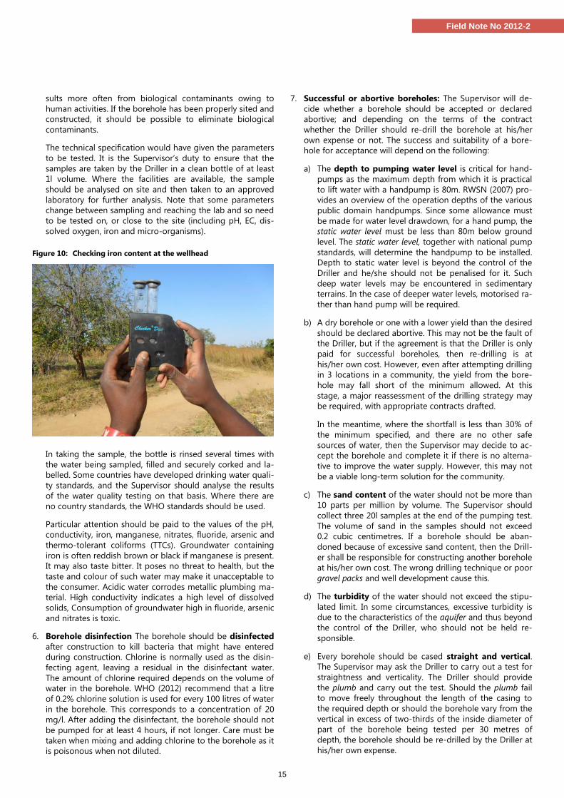
Figure 10: Checking iron content at the wellhead
In taking the sample, the bottle is rinsed several times with
the water being sampled, filled and securely corked and la-
belled. Some countries have developed drinking water quali-
ty standards, and the Supervisor should analyse the results
of the water quality testing on that basis. Where there are
no country standards, the WHO standards should be used.
Particular attention should be paid to the values of the pH,
conductivity, iron, manganese, nitrates, fluoride, arsenic and
thermo-tolerant coliforms (TTCs). Groundwater containing
iron is often reddish brown or black if manganese is present.
It may also taste bitter. It poses no threat to health, but the
taste and colour of such water may make it unacceptable to
the consumer. Acidic water corrodes metallic plumbing ma-
terial. High conductivity indicates a high level of dissolved
solids, Consumption of groundwater high in fluoride, arsenic
and nitrates is toxic.
6. Borehole disinfection The borehole should be disinfected
after construction to kill bacteria that might have entered
during construction. Chlorine is normally used as the disin-
fecting agent, leaving a residual in the disinfectant water.
The amount of chlorine required depends on the volume of
water in the borehole. WHO (2012) recommend that a litre
of 0.2% chlorine solution is used for every 100 litres of water
in the borehole. This corresponds to a concentration of 20
mg/l. After adding the disinfectant, the borehole should not
be pumped for at least 4 hours, if not longer. Care must be
taken when mixing and adding chlorine to the borehole as it
is poisonous when not diluted.
7. Successful or abortive boreholes: The Supervisor will de-
cide whether a borehole should be accepted or declared
abortive; and depending on the terms of the contract
whether the Driller should re-drill the borehole at his/her
own expense or not. The success and suitability of a bore-
hole for acceptance will depend on the following:
a) The depth to pumping water level is critical for hand-
pumps as the maximum depth from which it is practical
to lift water with a handpump is 80m. RWSN (2007) pro-
vides an overview of the operation depths of the various
public domain handpumps. Since some allowance must
be made for water level drawdown, for a hand pump, the
static water level must be less than 80m below ground
level. The static water level, together with national pump
standards, will determine the handpump to be installed.
Depth to static water level is beyond the control of the
Driller and he/she should not be penalised for it. Such
deep water levels may be encountered in sedimentary
terrains. In the case of deeper water levels, motorised ra-
ther than hand pump will be required.
b) A dry borehole or one with a lower yield than the desired
should be declared abortive. This may not be the fault of
the Driller, but if the agreement is that the Driller is only
paid for successful boreholes, then re-drilling is at
his/her own cost. However, even after attempting drilling
in 3 locations in a community, the yield from the bore-
hole may fall short of the minimum allowed. At this
stage, a major reassessment of the drilling strategy may
be required, with appropriate contracts drafted.
In the meantime, where the shortfall is less than 30% of
the minimum specified, and there are no other safe
sources of water, then the Supervisor may decide to ac-
cept the borehole and complete it if there is no alterna-
tive to improve the water supply. However, this may not
be a viable long-term solution for the community.
c) The sand content of the water should not be more than
10 parts per million by volume. The Supervisor should
collect three 20l samples at the end of the pumping test.
The volume of sand in the samples should not exceed
0.2 cubic centimetres. If a borehole should be aban-
doned because of excessive sand content, then the Drill-
er shall be responsible for constructing another borehole
at his/her own cost. The wrong drilling technique or poor
gravel packs and well development cause this.
d) The turbidity of the water should not exceed the stipu-
lated limit. In some circumstances, excessive turbidity is
due to the characteristics of the aquifer and thus beyond
the control of the Driller, who should not be held re-
sponsible.
e) Every borehole should be cased straight and vertical.
The Supervisor may ask the Driller to carry out a test for
straightness and verticality. The Driller should provide
the plumb and carry out the test. Should the plumb fail
to move freely throughout the length of the casing to
the required depth or should the borehole vary from the
vertical in excess of two-thirds of the inside diameter of
part of the borehole being tested per 30 metres of
depth, the borehole should be re-drilled by the Driller at
his/her own expense.
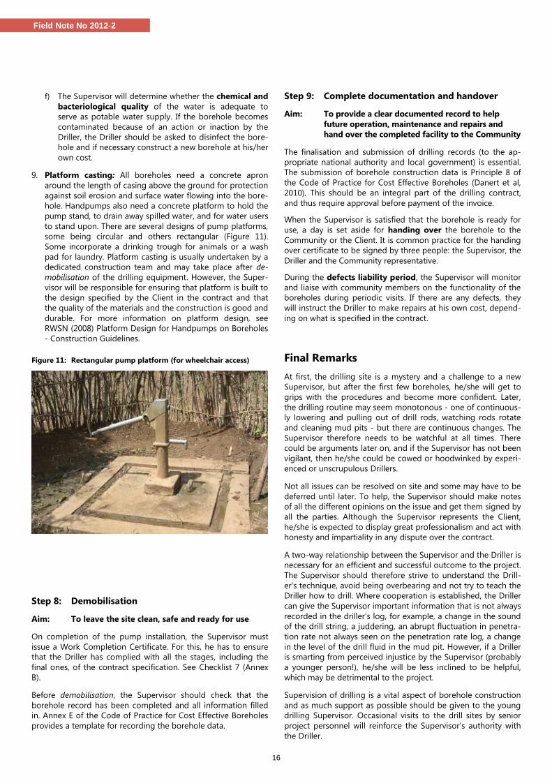
16
Field Note No 2012-2
f) The Supervisor will determine whether the chemical and
bacteriological quality of the water is adequate to
serve as potable water supply. If the borehole becomes
contaminated because of an action or inaction by the
Driller, the Driller should be asked to disinfect the bore-
hole and if necessary construct a new borehole at his/her
own cost.
9. Platform casting: All boreholes need a concrete apron
around the length of casing above the ground for protection
against soil erosion and surface water flowing into the bore-
hole. Handpumps also need a concrete platform to hold the
pump stand, to drain away spilled water, and for water users
to stand upon. There are several designs of pump platforms,
some being circular and others rectangular (Figure 11).
Some incorporate a drinking trough for animals or a wash
pad for laundry. Platform casting is usually undertaken by a
dedicated construction team and may take place after de-
mobilisation of the drilling equipment. However, the Super-
visor will be responsible for ensuring that platform is built to
the design specified by the Client in the contract and that
the quality of the materials and the construction is good and
durable. For more information on platform design, see
RWSN (2008) Platform Design for Handpumps on Boreholes
- Construction Guidelines.
Figure 11: Rectangular pump platform (for wheelchair access)
Step 8: Demobilisation
Aim: To leave the site clean, safe and ready for use
On completion of the pump installation, the Supervisor must
issue a Work Completion Certificate. For this, he has to ensure
that the Driller has complied with all the stages, including the
final ones, of the contract specification. See Checklist 7 (Annex
B).
Before demobilisation, the Supervisor should check that the
borehole record has been completed and all information filled
in. Annex E of the Code of Practice for Cost Effective Boreholes
provides a template for recording the borehole data.
Step 9: Complete documentation and handover
Aim: To provide a clear documented record to help
future operation, maintenance and repairs and
hand over the completed facility to the Community
The finalisation and submission of drilling records (to the ap-
propriate national authority and local government) is essential.
The submission of borehole construction data is Principle 8 of
the Code of Practice for Cost Effective Boreholes (Danert et al,
2010). This should be an integral part of the drilling contract,
and thus require approval before payment of the invoice.
When the Supervisor is satisfied that the borehole is ready for
use, a day is set aside for handing over the borehole to the
Community or the Client. It is common practice for the handing
over certificate to be signed by three people: the Supervisor, the
Driller and the Community representative.
During the defects liability period, the Supervisor will monitor
and liaise with community members on the functionality of the
boreholes during periodic visits. If there are any defects, they
will instruct the Driller to make repairs at his own cost, depend-
ing on what is specified in the contract.
Final Remarks
At first, the drilling site is a mystery and a challenge to a new
Supervisor, but after the first few boreholes, he/she will get to
grips with the procedures and become more confident. Later,
the drilling routine may seem monotonous - one of continuous-
ly lowering and pulling out of drill rods, watching rods rotate
and cleaning mud pits - but there are continuous changes. The
Supervisor therefore needs to be watchful at all times. There
could be arguments later on, and if the Supervisor has not been
vigilant, then he/she could be cowed or hoodwinked by experi-
enced or unscrupulous Drillers.
Not all issues can be resolved on site and some may have to be
deferred until later. To help, the Supervisor should make notes
of all the different opinions on the issue and get them signed by
all the parties. Although the Supervisor represents the Client,
he/she is expected to display great professionalism and act with
honesty and impartiality in any dispute over the contract.
A two-way relationship between the Supervisor and the Driller is
necessary for an efficient and successful outcome to the project.
The Supervisor should therefore strive to understand the Drill-
er’s technique, avoid being overbearing and not try to teach the
Driller how to drill. Where cooperation is established, the Driller
can give the Supervisor important information that is not always
recorded in the driller’s log, for example, a change in the sound
of the drill string, a juddering, an abrupt fluctuation in penetra-
tion rate not always seen on the penetration rate log, a change
in the level of the drill fluid in the mud pit. However, if a Driller
is smarting from perceived injustice by the Supervisor (probably
a younger person!), he/she will be less inclined to be helpful,
which may be detrimental to the project.
Supervision of drilling is a vital aspect of borehole construction
and as much support as possible should be given to the young
drilling Supervisor. Occasional visits to the drill sites by senior
project personnel will reinforce the Supervisor’s authority with
the Driller.
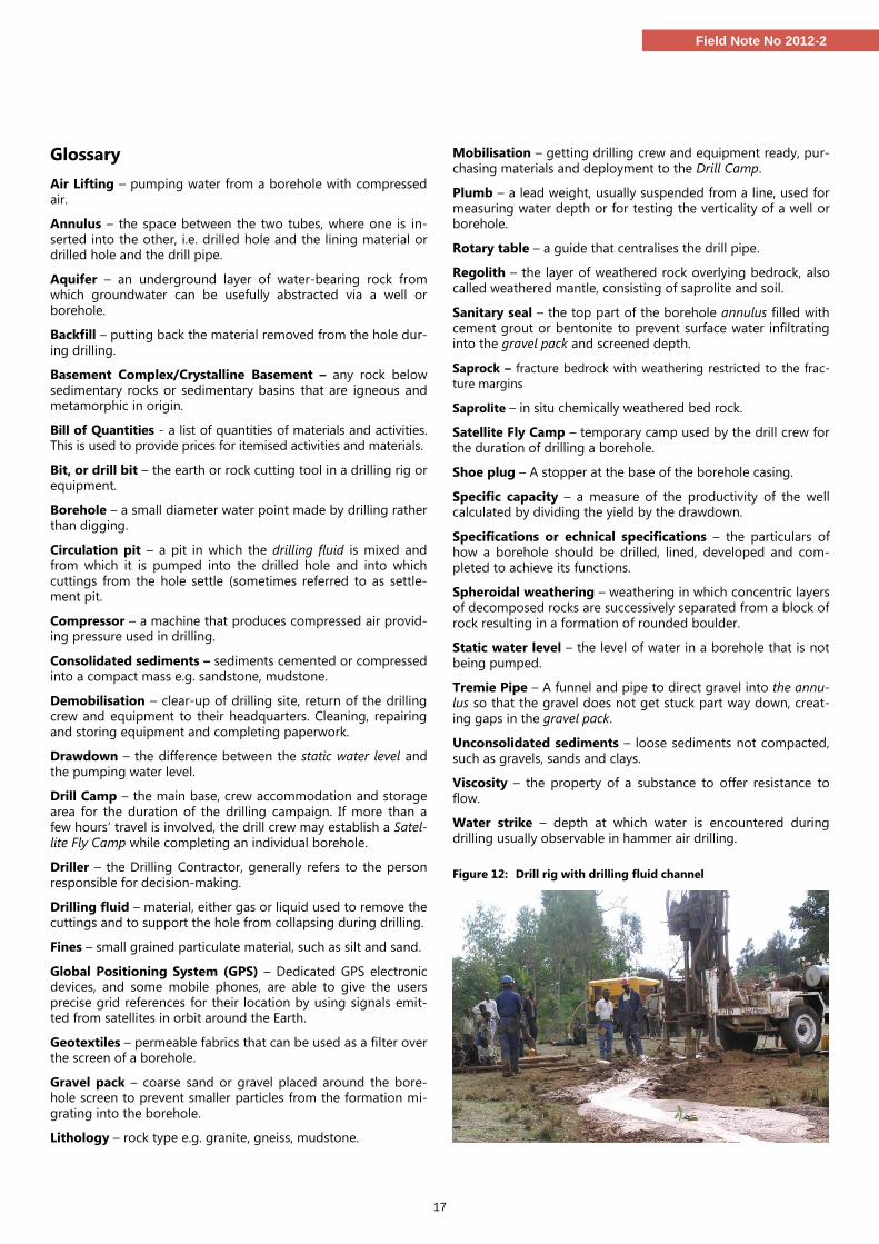
17
Field Note No 2012-2
Glossary
Air Lifting – pumping water from a borehole with compressed
air.
Annulus – the space between the two tubes, where one is in-
serted into the other, i.e. drilled hole and the lining material or drilled hole and the drill pipe.
Aquifer – an underground layer of water-bearing rock from which groundwater can be usefully abstracted via a well or
borehole.
Backfill – putting back the material removed from the hole dur-
ing drilling.
Basement Complex/Crystalline Basement – any rock below
sedimentary rocks or sedimentary basins that are igneous and metamorphic in origin.
Bill of Quantities - a list of quantities of materials and activities. This is used to provide prices for itemised activities and materials.
Bit, or drill bit – the earth or rock cutting tool in a drilling rig or equipment.
Borehole – a small diameter water point made by drilling rather than digging.
Circulation pit – a pit in which the drilling fluid is mixed and from which it is pumped into the drilled hole and into which
cuttings from the hole settle (sometimes referred to as settle-ment pit.
Compressor – a machine that produces compressed air provid-ing pressure used in drilling.
Consolidated sediments – sediments cemented or compressed into a compact mass e.g. sandstone, mudstone.
Demobilisation – clear-up of drilling site, return of the drilling crew and equipment to their headquarters. Cleaning, repairing
and storing equipment and completing paperwork.
Drawdown – the difference between the static water level and
the pumping water level.
Drill Camp – the main base, crew accommodation and storage
area for the duration of the drilling campaign. If more than a few hours’ travel is involved, the drill crew may establish a Satel-
lite Fly Camp while completing an individual borehole.
Driller – the Drilling Contractor, generally refers to the person
responsible for decision-making.
Drilling fluid – material, either gas or liquid used to remove the
cuttings and to support the hole from collapsing during drilling.
Fines – small grained particulate material, such as silt and sand.
Global Positioning System (GPS) – Dedicated GPS electronic devices, and some mobile phones, are able to give the users
precise grid references for their location by using signals emit-ted from satellites in orbit around the Earth.
Geotextiles – permeable fabrics that can be used as a filter over the screen of a borehole.
Gravel pack – coarse sand or gravel placed around the bore-hole screen to prevent smaller particles from the formation mi-
grating into the borehole.
Lithology – rock type e.g. granite, gneiss, mudstone.
Mobilisation – getting drilling crew and equipment ready, pur-
chasing materials and deployment to the Drill Camp.
Plumb – a lead weight, usually suspended from a line, used for
measuring water depth or for testing the verticality of a well or borehole.
Rotary table – a guide that centralises the drill pipe.
Regolith – the layer of weathered rock overlying bedrock, also
called weathered mantle, consisting of saprolite and soil.
Sanitary seal – the top part of the borehole annulus filled with
cement grout or bentonite to prevent surface water infiltrating into the gravel pack and screened depth.
Saprock – fracture bedrock with weathering restricted to the frac-
ture margins
Saprolite – in situ chemically weathered bed rock.
Satellite Fly Camp – temporary camp used by the drill crew for
the duration of drilling a borehole.
Shoe plug – A stopper at the base of the borehole casing.
Specific capacity – a measure of the productivity of the well calculated by dividing the yield by the drawdown.
Specifications or echnical specifications – the particulars of how a borehole should be drilled, lined, developed and com-
pleted to achieve its functions.
Spheroidal weathering – weathering in which concentric layers
of decomposed rocks are successively separated from a block of rock resulting in a formation of rounded boulder.
Static water level – the level of water in a borehole that is not being pumped.
Tremie Pipe – A funnel and pipe to direct gravel into the annu-lus so that the gravel does not get stuck part way down, creat-
ing gaps in the gravel pack.
Unconsolidated sediments – loose sediments not compacted,
such as gravels, sands and clays.
Viscosity – the property of a substance to offer resistance to
flow.
Water strike – depth at which water is encountered during
drilling usually observable in hammer air drilling.
Figure 12: Drill rig with drilling fluid channel
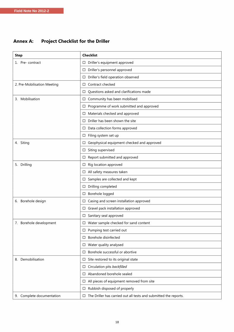
18
Field Note No 2012-2
Annex A: Project Checklist for the Driller
Step Checklist
1. Pre- contract Driller’s equipment approved
Driller’s personnel approved
Driller’s field operation observed
2. Pre-Mobilisation Meeting Contract checked
Questions asked and clarifications made
3. Mobilisation Community has been mobilised
Programme of work submitted and approved
Materials checked and approved
Driller has been shown the site
Data collection forms approved
Filing system set up
4. Siting Geophysical equipment checked and approved
Siting supervised
Report submitted and approved
5. Drilling Rig location approved
All safety measures taken
Samples are collected and kept
Drilling completed
Borehole logged
6. Borehole design Casing and screen installation approved
Gravel pack installation approved
Sanitary seal approved
7. Borehole development Water sample checked for sand content
Pumping test carried out
Borehole disinfected
Water quality analysed
Borehole successful or abortive
8. Demobilisation Site restored to its original state
Circulation pits backfilled
Abandoned borehole sealed
All pieces of equipment removed from site
Rubbish disposed of properly
9. Complete documentation The Driller has carried out all tests and submitted the reports.
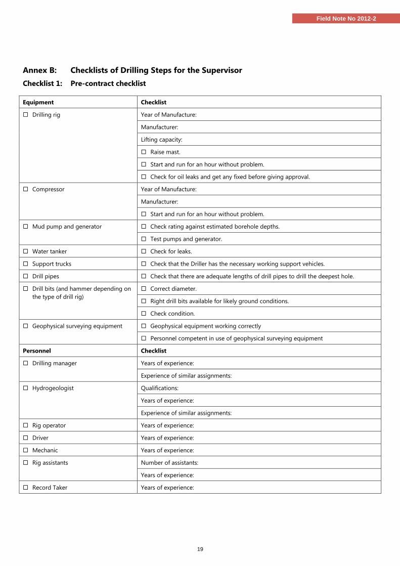
19
Field Note No 2012-2
Annex B: Checklists of Drilling Steps for the Supervisor
Checklist 1: Pre-contract checklist
Equipment Checklist
Drilling rig Year of Manufacture:
Manufacturer:
Lifting capacity:
Raise mast.
Start and run for an hour without problem.
Check for oil leaks and get any fixed before giving approval.
Compressor Year of Manufacture:
Manufacturer:
Start and run for an hour without problem.
Mud pump and generator Check rating against estimated borehole depths.
Test pumps and generator.
Water tanker Check for leaks.
Support trucks Check that the Driller has the necessary working support vehicles.
Drill pipes Check that there are adequate lengths of drill pipes to drill the deepest hole.
Drill bits (and hammer depending on
the type of drill rig)
Correct diameter.
Right drill bits available for likely ground conditions.
Check condition.
Geophysical surveying equipment Geophysical equipment working correctly
Personnel competent in use of geophysical surveying equipment
Personnel Checklist
Drilling manager Years of experience:
Experience of similar assignments:
Hydrogeologist Qualifications:
Years of experience:
Experience of similar assignments:
Rig operator Years of experience:
Driver Years of experience:
Mechanic Years of experience:
Rig assistants Number of assistants:
Years of experience:
Record Taker Years of experience:
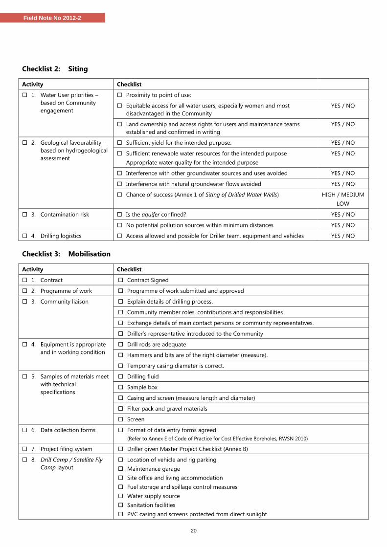
20
Field Note No 2012-2
Checklist 2: Siting
Activity Checklist
1. Water User priorities –
based on Community
engagement
Proximity to point of use:
Equitable access for all water users, especially women and most
disadvantaged in the Community
YES / NO
Land ownership and access rights for users and maintenance teams
established and confirmed in writing
YES / NO
2. Geological favourability -
based on hydrogeological
assessment
Sufficient yield for the intended purpose: YES / NO
Sufficient renewable water resources for the intended purpose
Appropriate water quality for the intended purpose
YES / NO
Interference with other groundwater sources and uses avoided YES / NO
Interference with natural groundwater flows avoided YES / NO
Chance of success (Annex 1 of Siting of Drilled Water Wells) HIGH / MEDIUM
LOW
3. Contamination risk Is the aquifer confined? YES / NO
No potential pollution sources within minimum distances YES / NO
4. Drilling logistics Access allowed and possible for Driller team, equipment and vehicles YES / NO
Checklist 3: Mobilisation
Activity Checklist
1. Contract Contract Signed
2. Programme of work Programme of work submitted and approved
3. Community liaison Explain details of drilling process.
Community member roles, contributions and responsibilities
Exchange details of main contact persons or community representatives.
Driller’s representative introduced to the Community
4. Equipment is appropriate
and in working condition
Drill rods are adequate
Hammers and bits are of the right diameter (measure).
Temporary casing diameter is correct.
5. Samples of materials meet
with technical
specifications
Drilling fluid
Sample box
Casing and screen (measure length and diameter)
Filter pack and gravel materials
Screen
6. Data collection forms Format of data entry forms agreed
(Refer to Annex E of Code of Practice for Cost Effective Boreholes, RWSN 2010)
7. Project filing system Driller given Master Project Checklist (Annex B)
8. Drill Camp / Satellite Fly
Camp layout
Location of vehicle and rig parking
Maintenance garage
Site office and living accommodation
Fuel storage and spillage control measures
Water supply source
Sanitation facilities
PVC casing and screens protected from direct sunlight
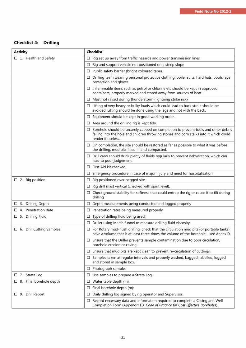
21
Field Note No 2012-2
Checklist 4: Drilling
Activity Checklist
1. Health and Safety Rig set up away from traffic hazards and power transmission lines
Rig and support vehicle not positioned on a steep slope
Public safety barrier (bright coloured tape).
Drilling team wearing personal protective clothing: boiler suits, hard hats, boots, eye
protection and gloves
Inflammable items such as petrol or chlorine etc should be kept in approved
containers, properly marked and stored away from sources of heat.
Mast not raised during thunderstorm (lightning strike risk)
Lifting of very heavy or bulky loads which could lead to back strain should be
avoided. Lifting should be done using the legs and not with the back.
Equipment should be kept in good working order.
Area around the drilling rig is kept tidy.
Borehole should be securely capped on completion to prevent tools and other debris
falling into the hole and children throwing stones and corn stalks into it which could
render it useless.
On completion, the site should be restored as far as possible to what it was before
the drilling, mud pits filled in and compacted.
Drill crew should drink plenty of fluids regularly to prevent dehydration, which can
lead to poor judgement.
First Aid kit checked
Emergency procedure in case of major injury and need for hospitalisation
2. Rig position Rig positioned over pegged site.
Rig drill mast vertical (checked with spirit level).
Check ground stability for softness that could entrap the rig or cause it to tilt during
drilling
3. Drilling Depth Depth measurements being conducted and logged properly
4. Penetration Rate Penetration rates being measured properly
5. Drilling Fluid Type of drilling fluid being used:
Driller using Marsh funnel to measure drilling fluid viscosity
6. Drill Cutting Samples For Rotary mud-flush drilling, check that the circulation mud pits (or portable tanks)
have a volume that is at least three times the volume of the borehole – see Annex D.
Ensure that the Driller prevents sample contamination due to poor circulation,
borehole erosion or caving.
Ensure that mud pits are kept clean to prevent re-circulation of cuttings.
Samples taken at regular intervals and properly washed, bagged, labelled, logged
and stored in sample box.
Photograph samples
7. Strata Log Use samples to prepare a Strata Log.
8. Final borehole depth Water table depth (m):
Final borehole depth (m):
9. Drill Report Daily drilling log signed by rig operator and Supervisor.
Record necessary data and information required to complete a Casing and Well
Completion Form (Appendix E3, Code of Practice for Cost Effective Boreholes).
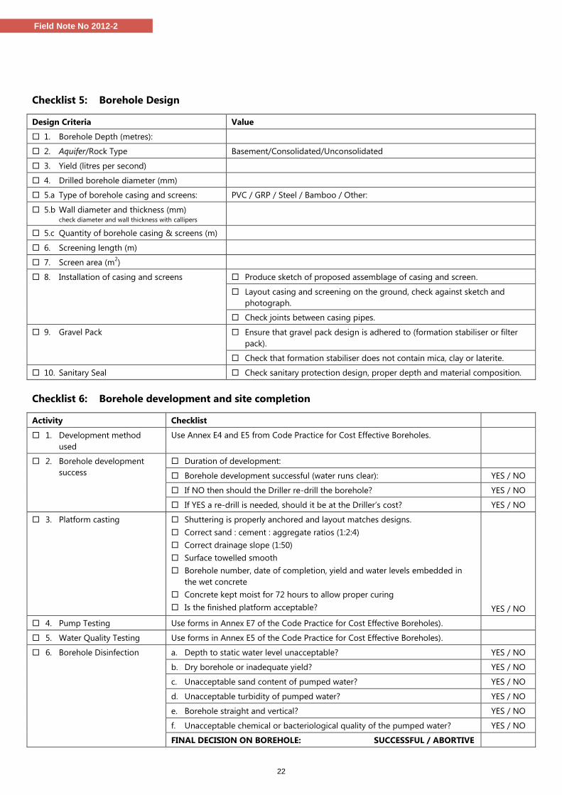
22
Field Note No 2012-2
Checklist 5: Borehole Design
Design Criteria Value
1. Borehole Depth (metres):
2. Aquifer/Rock Type Basement/Consolidated/Unconsolidated
3. Yield (litres per second)
4. Drilled borehole diameter (mm)
5.a Type of borehole casing and screens: PVC / GRP / Steel / Bamboo / Other:
5.b Wall diameter and thickness (mm) check diameter and wall thickness with callipers
5.c Quantity of borehole casing & screens (m)
6. Screening length (m)
7. Screen area (m2)
8. Installation of casing and screens Produce sketch of proposed assemblage of casing and screen.
Layout casing and screening on the ground, check against sketch and
photograph.
Check joints between casing pipes.
9. Gravel Pack Ensure that gravel pack design is adhered to (formation stabiliser or filter
pack).
Check that formation stabiliser does not contain mica, clay or laterite.
10. Sanitary Seal Check sanitary protection design, proper depth and material composition.
Checklist 6: Borehole development and site completion
Activity Checklist
1. Development method
used
Use Annex E4 and E5 from Code Practice for Cost Effective Boreholes.
2. Borehole development
success
Duration of development:
Borehole development successful (water runs clear): YES / NO
If NO then should the Driller re-drill the borehole? YES / NO
If YES a re-drill is needed, should it be at the Driller’s cost? YES / NO
3. Platform casting Shuttering is properly anchored and layout matches designs.
Correct sand : cement : aggregate ratios (1:2:4)
Correct drainage slope (1:50)
Surface towelled smooth
Borehole number, date of completion, yield and water levels embedded in
the wet concrete
Concrete kept moist for 72 hours to allow proper curing
Is the finished platform acceptable?
YES / NO
4. Pump Testing Use forms in Annex E7 of the Code Practice for Cost Effective Boreholes).
5. Water Quality Testing Use forms in Annex E5 of the Code Practice for Cost Effective Boreholes).
6. Borehole Disinfection a. Depth to static water level unacceptable? YES / NO
b. Dry borehole or inadequate yield? YES / NO
c. Unacceptable sand content of pumped water? YES / NO
d. Unacceptable turbidity of pumped water? YES / NO
e. Borehole straight and vertical? YES / NO
f. Unacceptable chemical or bacteriological quality of the pumped water? YES / NO
FINAL DECISION ON BOREHOLE: SUCCESSFUL / ABORTIVE
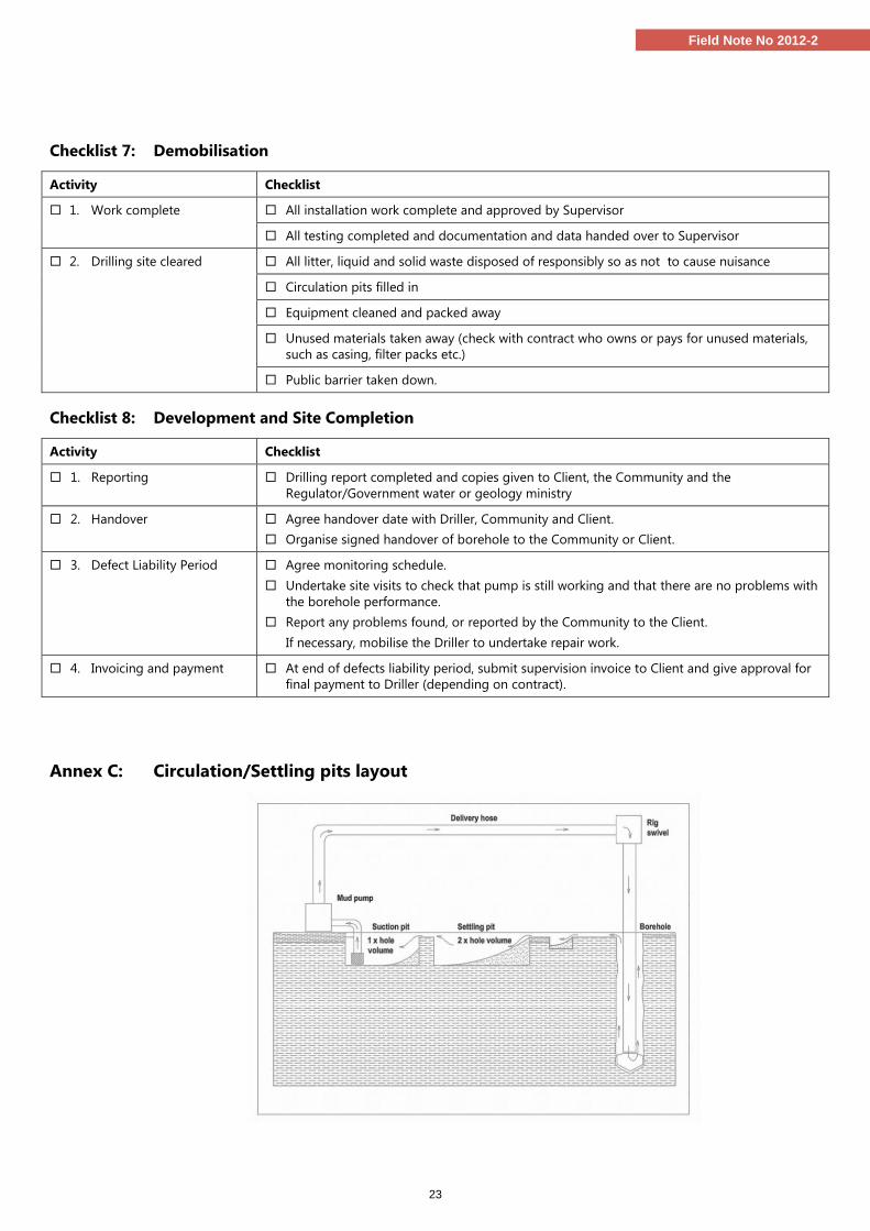
23
Field Note No 2012-2
Checklist 7: Demobilisation
Activity Checklist
1. Work complete All installation work complete and approved by Supervisor
All testing completed and documentation and data handed over to Supervisor
2. Drilling site cleared All litter, liquid and solid waste disposed of responsibly so as not to cause nuisance
Circulation pits filled in
Equipment cleaned and packed away
Unused materials taken away (check with contract who owns or pays for unused materials,
such as casing, filter packs etc.)
Public barrier taken down.
Checklist 8: Development and Site Completion
Activity Checklist
1. Reporting Drilling report completed and copies given to Client, the Community and the
Regulator/Government water or geology ministry
2. Handover Agree handover date with Driller, Community and Client.
Organise signed handover of borehole to the Community or Client.
3. Defect Liability Period Agree monitoring schedule.
Undertake site visits to check that pump is still working and that there are no problems with
the borehole performance.
Report any problems found, or reported by the Community to the Client.
If necessary, mobilise the Driller to undertake repair work.
4. Invoicing and payment At end of defects liability period, submit supervision invoice to Client and give approval for
final payment to Driller (depending on contract).
Annex C: Circulation/Settling pits layout

References and Bibliography ADEKILE, D (2012) Procurement and Contract Management of Drilled Well Construction: A Guide for Supervisors and Project Managers, RWSN Field Note
2012-4, Rural Water Supply Network, St Gallen, Switlerland
ADEKILE, D. and BALL, P. (2006) Training local technicians in borehole drilling –Waterlines Vol.24 No4. Practical Action, UK
ADEKILE, D. and KWEI, C. (2009) The Code of Practice for Cost Effective Boreholes in Ghana – Country Status Report, Consultancy Report for the Rural Water Supply Network, St Gallen, Switzerland
ADEKILE, D. and OLABODE O. (2008) Study of Public and Private Borehole Drilling in Nigeria. Consultancy Report for UNICEF Nigeria Wash Section and Rural Water Supply Network, St Gallen, Switzerland
ANSCOMBE (2012), Personal Communication with the editors when reviewing this publication, August 2012.
ARMSTRONG, T. 2009. The Code of Practice for Cost Effective Boreholes in Zambia – Country Status Report, Consultancy Report for UNICEF and Rural Water Supply Network, St Gallen, Switzerland
BALL, P (2001) Drilled Wells SKAT, Swiss Centre for Development Cooperation in Technology and Management, St Gallen, Switzerland
BALL, P. (2004) Solutions for Reducing Borehole Costs in Africa WSP/Rural Water Supply Network, St Gallen, Switzerland
BOODE Water Well Systems (2011) PVC Screen and casing standard type 1” to 3” lengthwise slotted. Available from: http://www.boode.com/index2.html/
CARTER, RC., CHILTON, J., DANERT, K. & OLSCHEWSKI, A. (2010) Siting of Drilled Water Wells - A Guide for Project Managers. RWSN Field Note 2010-5, Rural Water Supply Network (RWSN) , St Gallen, Switzerland,
CARTER, RC. (2006) Ten-step Guide Towards Cost-effective Boreholes. Rural Water Supply Network, St Gallen, Switzerland
DANERT, K., ARMSTRONG, T., ADEKILE, D., DUFFAU, B., OUEDRAOGO, I. & KWEI, C. (2010) Code of Practice for Cost Effective Boreholes. British English Version, June 2010, Rural Water Supply Network (RWSN), St Gallen, Switzerland.
DANERT, K., LUUTU, A., CARTER, RC., OLSCHEWSKI, A ((2010) Costing and Pricing - A Guide for Water Well Drilling Enterprises. RWSN Field Note 2010-6, Rural Water Supply Network (RWSN), St Gallen, Switzerland,
DRISCOLL, F. (1986) Groundwater and Wells, St Paul: Johnson Division
ELSON B and SHAW R (2011) Simple Drilling Methods WEDC Technical Briefs 43, WEDC Loughborough University http://www.lboro.ac.uk/well/resources/technical-briefs/43-simple-drilling-methods.pdfa [accessed 2 August 2011]
FUREY, S (2012) Sustainable Groundwater Development: use, protect and enhance, Rural Water Supply Network (RWSN).
FEDERAL REPUBLIC OF NIGERIA/NATIONAL WATER RESOURCES INSTITUTE. 2009. National Code of Practice for Water Well Construction in Nigeria, National Water Resources Institute, Kaduna, Nigeria
MACDONALD, A. DAVIES, J. CALOW, R. and CHILTON, J. (2005) Developing Groundwater. A guide for Rural Water Supply, ITDG Publishing
MICHAEL, A.M. and KHEPAR, S.D. (1989) Water Well and Pump Engineering Tata McGraw – Hill Publishing Company Limited, New Delhi
NATIONAL WATER RESOURCES INSTITUTE. (2010) Short Course 2 Borehole Construction and Management Rural water Supply and Sanitation Centre
RWSN (2007) Technology Selection – and Buyer’s guide for Public Domain Handpumps for Drinking Water, Rural Water Supply Network
RWSN (2008) Platform Design for Handpumps on Boreholes - Construction Guidelines (Revision 1-2008), Rural Water Supply Network
RWSN (2009) Hand Drilling Directory, Rural Water Supply Network.
UNICEF (2010a) UNICEF WASH Technology Information Packages (TIPs), Available from http://www.unicef.org/supply/index_54301.html
UNICEF (2010b) Professionalising the Manual Drilling Sector, UNICEF, Available from http://www.unicef.org/wash/files/1._Professionalizing_Manual_Drilling_lo_res.pdf
WATERLINES (1995) Technical Brief No. 43 Simple Drilling Methods, Waterlines Vol. 13 No. 3, January 1995. Available from http://www.lboro.ac.uk/well/resources/technical-briefs/43-simple-drilling-methods.pdf
WE Consult 2011 Supervision tables Water, Environment & Geo Services Ltd Kampala Uganda
WHO (2012) Cleaning and Disinfecting boreholes, WHO Technical Note for Emergencies No 2, Available on http://www.who.int/water_sanitation_health/hygiene/envsan/tn02/en/ [Accessed 3 August 2011]
WHO (2008) Guidelines for Drinking Water Quality, Incorporating First and Second Addenda to Third Edition, Volume 1 Recommendations, World Health Organisation, Geneva, Switzerland. Available from: http://www.who.int/water_sanitation_health/dwq/gdwq3rev/en/ [accessed 22 June 2012]
WHO/UNICEF (2011) Drinking Water: Equity, Safety and Sustainability, JMP Thematic Report on Drinking Water 2011. Available from: http://www.wssinfo.org/fileadmin/user_upload/resources/report_wash_low.pdf [accessed 26 May 2012]
WHO/UNICEF (2012) Joint Monitoring Programme Report 2012 Progress on Water and Sanitation and Drinking Water. Available from http://www.wssinfo.org/fileadmin/user_upload/resources/JMP-report-2012-en.pdf [accessed 24 May 2012]
About the Author Support and Acknowledgement
Dotun Adekile is a Nigerian consultant with over 30 years of experience
siting and supervising borehole construction, as well as training field
geologists and technicians. He has contributed to developing the Code
of Practice for Cost Effective Boreholes in three countries and the
preparation of several guidance notes.
Although this document derives from the author’s years of drilling
supervision, similar works on the subject were consulted in its
preparation. Some of the authors are mentioned in the text but for
brevity of presentation others are not. All the sources consulted are
listed in the bibliography. The author gratefully acknowledges their
contribution.
Particular gratitude goes to Kerstin Danert, Ron Sloots, Robin Ha-
zell, Richard Carter, André Olschewski and Jim Anscombe who
reviewed this document.
This document was supported by UNICEF and Skat Foundation
The document was edited by Sean Furey and Kerstin Danert
Layout was undertaken by Martin Laeng
Photo Credits: The author, Richard Carter, Hazel Jones, WEDC and
Jim Anscombe.
ISBN: 978-3-908156-42-0
Contact
The Rural Water supply Network
(RWSN) is a global knowledge network
for promoting sound practices in rural
water supply.
RWSN Secretariat Phone: +41 71 228 54 54
SKAT Foundation Fax: +41 71 228 54 55
Vadianstrasse 42 Email: [email protected]
CH-9000 St.Gallen Web: www.rural-water-supply.net
Switzerland
This publication can be downloaded from http://www.rural-water-supply.net with all other RWSN publications.
Related Documents