Chapter 4 Ground-Water-Data Collection DRILLING AND WELL CONSTRUCTION Many ground-water studies, particularly those intended to determine, in detail, the distribution of contaminants or hydraulic properties of aquifers, require the installation of monitoring wells to supplement existing wells. Existing wells may be poorly constructed; not have available lithologic data (geologic units encountered) and construction information (well depth, length/type of open interval); may be used for water supply (which can affect the quality of samples collected); and (or) require special permission (or not permitted) for use). Most wells installed for ground-water studies are two-inch diameter wells, which have the benefit of allowing the use of existing small diameter sampling pumps, limiting purge time and volume, and reducing installation costs. Larger-diameter wells (4- to 6- inch diameter) also may be installed, generally as pumping wells for multiple-well aquifer tests and contaminant extraction systems (Lapham and others, 1977). A properly constructed well is intended to provide water and pressure data from the aquifer of interest only will not contribute erroneous water-quality results because of leaching and adsorption by the well casing, screen, or backfilling materials, or from liquids or other additives used during drilling. (BEWARE THE “ENEMIES”) USEFUL REFERENCES: Lapham, W. W., Wilde, F.D., and Koterba, M.T., 1997, Guidelines and standard Procedures for studies of ground-water quality: selection and installation of wells, and supporting documentation: U.S. Geological Survey Water-Resources Investigations Report 96-4233, 110 p. U.S. EPA, 1991, Handbook of suggested practices for the design and installation of ground-water monitoring wells: EPA/600/4-89/034 Shuter, E. and Teasdale, W.E., 1989, Application of drilling, coring, and sampling techniques to test holes and wells: U.S. Geological Survey Techniques of Water- Resources Investigations of the United States Geological Survey, Book 2, Chapter F1, 97 p. The process of well installation requires: • Establishing installation criteria • to ensure wells installed for intended purpose and will yield data that accurately represents the hydrogeologic system and its water quality • each aspect of well installation will comply with appropriate regulations, utilities; will be identified, safety issues considered • Designing wells – compatibility with data objectives • Whenever possible design well to meet needs of future studies • Considerations • nature of subsurface materials (unconsolidated?, fractured?) 170

Welcome message from author
This document is posted to help you gain knowledge. Please leave a comment to let me know what you think about it! Share it to your friends and learn new things together.
Transcript

Chapter 4 Ground-Water-Data Collection
DRILLING AND WELL CONSTRUCTION Many ground-water studies, particularly those intended to determine, in detail, the distribution of contaminants or hydraulic properties of aquifers, require the installation of monitoring wells to supplement existing wells. Existing wells may be poorly constructed; not have available lithologic data (geologic units encountered) and construction information (well depth, length/type of open interval); may be used for water supply (which can affect the quality of samples collected); and (or) require special permission (or not permitted) for use). Most wells installed for ground-water studies are two-inch diameter wells, which have the benefit of allowing the use of existing small diameter sampling pumps, limiting purge time and volume, and reducing installation costs. Larger-diameter wells (4- to 6-inch diameter) also may be installed, generally as pumping wells for multiple-well aquifer tests and contaminant extraction systems (Lapham and others, 1977). A properly constructed well is intended to provide water and pressure data from the aquifer of interest only will not contribute erroneous water-quality results because of leaching and adsorption by the well casing, screen, or backfilling materials, or from liquids or other additives used during drilling. (BEWARE THE “ENEMIES”) USEFUL REFERENCES: Lapham, W. W., Wilde, F.D., and Koterba, M.T., 1997, Guidelines and standard Procedures for studies of ground-water quality: selection and installation of wells,
and supporting documentation: U.S. Geological Survey Water-Resources Investigations Report 96-4233, 110 p.
U.S. EPA, 1991, Handbook of suggested practices for the design and installation of
ground-water monitoring wells: EPA/600/4-89/034 Shuter, E. and Teasdale, W.E., 1989, Application of drilling, coring, and sampling techniques to test holes and wells: U.S. Geological Survey Techniques of Water- Resources Investigations of the United States Geological Survey, Book 2, Chapter F1, 97 p. The process of well installation requires: • Establishing installation criteria
• to ensure wells installed for intended purpose and will yield data that accurately represents the hydrogeologic system and its water quality
• each aspect of well installation will comply with appropriate regulations, utilities; will be identified, safety issues considered
• Designing wells – compatibility with data objectives
• Whenever possible design well to meet needs of future studies • Considerations
• nature of subsurface materials (unconsolidated?, fractured?)
170
Chapter 4 Ground-Water-Data Collection
• relation between subsurface material/screen selection • casing and screen material
• typically PVC or stainless steel, may be PTFE (NSF approved) • leaching-sorption advantages/disadvantages • avoid PVC solvents/cement • flush threaded with o-rings
• aperture has sufficient open area • screen length and type (affect water quality, hydraulic measurements)
• typically continuous wire-wound or machine slotted • open area (aperture) sufficient to allow sample be withdrawn
without entrainment of sediment; based on size of sediment (often 10-slot or 0.01 ft aperture)
• diameter casing/screen/ or open hole • depth to water • depth to top of aquifer • depth to monitoring interval (tensile strength important with depth)
• Schedule 80 PVC generally recommended for wells > 100 ft • operational issues (budget, site accessibility; equipment access)
• well may be open hole w/ surface casing; open hole with packers; screen well and casing with filter pack, annular seal
• Decontaminating the equipment; selecting the appropriate drilling, construction,
completion, and development methods.
DRILLING FOR INSTALLING WELLS FOR WATER-QUALITY SAMPLING AND HYDRAULIC TESTING
Select method that minimizes contamination of subsurface materials and pore water
by foreign drilling fluids and minimizes cross contamination vertically between subsurface materials during drilling. AUGER DRILLING
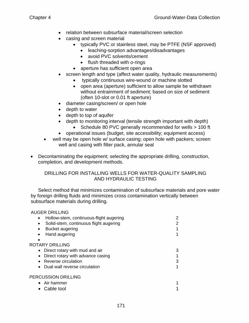
• Hollow-stem, continuous-flight augering 2 • Solid-stem, continuous flight augering 2 • Bucket augering 1 • Hand augering 1 •
ROTARY DRILLING • Direct rotary with mud and air 3 • Direct rotary with advance casing 1 • Reverse circulation 3 • Dual wall reverse circulation 1
PERCUSSION DRILLING
• Air hammer 1 • Cable tool 1
171
Chapter 4 Ground-Water-Data Collection
• Jet wash 3 • Jet percussion 3 • Hand driving 1
1. Most preferred because avoids use of drilling fluids, and drill casing
advanced during drilling 2. Avoid use of drilling fluids, but drill rod not advanced during drilling. 3. Least preferred because uses drilling fluids, and drill casing not Advanced during drilling.
Consider these issues when selecting drilling method:
• Introduction of air into aquifer (avoid air rotary?) • Introduction of oil (from air) into aquifer (avoid air rotary?) • Cross contamination between aquifers (use advanced-casing method?) • Introduction of drilling fluids (bentonite mud) into aquifer (avoid mud rotary?) • Cost and Speed
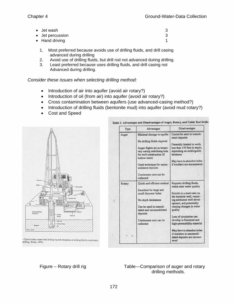
Figure – Rotary drill rig Table—Comparison of auger and rotary drilling methods.
172

Chapter 4 Ground-Water-Data Collection
Rotary drilling will produce a skin of fine-grain materials (mud cake) on the borehole wall. The cake will consist of rock flour produced during drilling and drilling fluids (generally bentonite mud). The drilling fluid can penetrate into the formation. The drilling fluids and fine-grained materials in the “screened” interval must be removed upon completion of well installation.
WELL CONSTRUCTION
Figures – Examples of various well constructions
WELL COMPLETION
• Well completion consists of filling and sealing the annular space between the well casing and borehole wall to ensure that:
• The hydraulic head measured in the well is that of the “screened” interval • Only the interval “screened” contributes water to the well • There is no vertical conduit along the annulus for flow of water and
contaminants
173

Chapter 4 Ground-Water-Data Collection
WELL SCREEN SLOT-SIZE SELECTION • On basis of grain-size distribution
• Effective size = 90 % retained (D10) • Uniformity coefficient = ration of 40% retained (D60) to effective size
• Justify natural filter packs if: • D10>0.01 inch • D60/D10 >3.0
• Most designers install standard 10-slot screen; may lead to problems with well development and performance
ARTIFICIAL FILTER PACK REQUIREMENTS • use if fine-grained materials present; with long screens in highly stratified, non-
uniform sediments; in bedrock with fractures • 20-slot or less screen opening is required to retain 50% of material • select filter-pack size/screen-opening size at same time
• too large a filter pack/slot size, fines are lost to well • too small, filter pack lost to aquifer, unstable filter pack uniform pack = better filtering,
better placement
Table and figure. – Selection criteria for proper filter pack and screen size
174
Chapter 4 Ground-Water-Data Collection
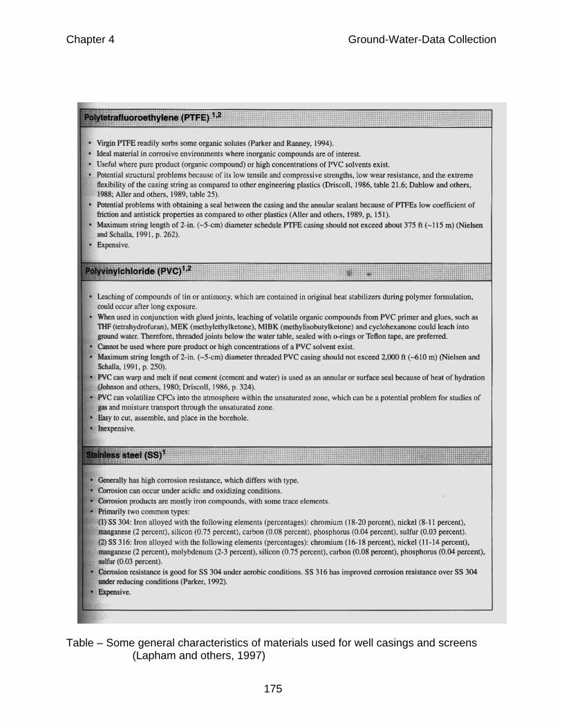
Table – Some general characteristics of materials used for well casings and screens (Lapham and others, 1997)
175

Chapter 4 Ground-Water-Data Collection
GENERAL CHARACTERISTICS OF MATERIALS FOR WELL COMPLETION • Primary filter pack
• An envelope of sediment backfilled around the screen • Grain size should be similar to the prevailing grain size of the screened unit • Consists of well sorted quartz sand or gravel • Should not contain carbonate material • Should not contain organic material (wood fragments) • Best placed by a tremie pipe, backfilling slowly from the bottom to 1-5 ft
above top of the screen • Secondary filter pack
• Purpose is to prevent the overlying grout from infiltrating and clogging the primary filter pack
• Length of about 1 ft • Alternative is a primary filter pack that extends a minimum of 5 ft above the
top of the screen • Plugs consisting of a packing shoe or a cement basket shoe not be
substituted because of possible effects on water quality • Grain size of the secondary filter pack should be intermediate between the
grain sizes of the primary filter pack and grout • Consists of well-sorted quartz sand • Should not contain carbonate material • Best placed with a tremie pipe
• Grout
• Purpose is to seal annulus above secondary filter pack • Ideal grout is chemically inert, permanent, stable, and resists chemical and
physical deterioration • Commonly used grouts are bentonite, cement,mixtures of bentonite and
cement • In general, high solids bentonite is recommended material • Bentonite-cement mixture limits affect cement shrinkage • Use Portland Type I cement – no additives • Best placed with a tremie pipe
• Surface seal
• A cement platform providing a seal at land surface that: • Prevents surface runoff down the well annulus • Holds the protective casing in place
• Installed to a depth from land surface to prevent frost heaving (in general about 3 ft)
• Bentonite not recommended because of likely desiccation • Protective casing: steel casing with vented (weep hole), locking cover
176
Chapter 4 Ground-Water-Data Collection
WELL DEVELOPMENT
Well development is a process of removing the fine grained material from the part of the filter pack around the well screen (Ideal filter pack90% retained by screen/10% will pass through the screen. Usually less retained) by pumping, surging, bailing, or otherwise removing many well-volumes of water from the well. This is necessary so that when the well is sampled, an absolute minimum of silt and slay will be present in the sample and the hydraulic characteristics of the filter pack do not limit accurate assessment of the hydraulic properties of the aquifer. The removal of the water needs to be at a rate sufficient to create velocities that will remove the fine particles. Generally, the well is pumped at a conservative rate so as not to create a severe gradient which could disturb the placement of the filter pack. If rotary drilling was used to construct the hole and drilling mud was used, well development can require days or weeks. This is usually not the case for shallow monitoring wells constructed in unconsolidated sediments or bedrock wells drilled by percussion or water rotary. The pumping or bailing associated with monitoring well development usually only continues until a minimum of turbidity is present. Bedrock boreholes consisting of an open hole in the bedrock and a surface casing cemented into upper part of the bedrock unit and grouted where it penetrates the overlying unconsolidated deposits must be developed before the borehole can be sampled, used for hydraulic tests, or packer tested. Goals of development for these holes are similar to those for monitoring wells; pumping rates may greatly exceed those used for monitoring wells • Objectives
• To remove fine-grained sediments and drilling fluids introduced into formations during drilling
• To provide water free of suspended solids to reduce pump wear • To provide water free of suspended solids for sampling (fines may affect
water-quality results, particularly trace metals) • Eliminate bridging in filter pack • Removes water introduced during drilling
• Goals
• Typically a minimum of 10 well volumes • Typically a goal of 5 nephalometric turbidity units (NTU’s) • Typically a rate of 2.5 – 10 gallons per minute; may approach 30 gal/min for
bedrock boreholes • Well Development Methods (often used in combination)
• Backwashing • Water injected out into subsurface materials
• Surging (surge block) • Water injected out into subsurface materials then drawn back into well
• Pumping or Overpumping
177

Chapter 4 Ground-Water-Data Collection
• Well Development Methods (often used in combination)--continued
• Water withdrawn from well • Bailing
• Water drawn back into the well • Jetting with water or air
• Water, air, or both injected out into subsurface materials, then removed from the well
Well Development Methods in order of preference for water-quality sampling
• Best method includes surge in both directions combined with pumping • Bailing • Mechanical surging • Pumping or Overpumping and Backwashing • Indirect Eduction Jetting • Backwashing • Jetting or Surging with Water or Air • Avoid methods that:
• introduce water into the aquifer • introduce air into the aquifer (Fe bacterial/biologic activity) • pushes fines into sandpack
DRILLING SAFETY Reference: Drilling Safety Guide, International Drilling Federation Drilling can be very dangerous. Heavy equipment is used that can injure back feet, hands, etc. Additionally, drilling in the immediate vicinity of electrical lines or underground utilities one risks, electrical shock, explosions, vaporous releases and other responses that could result in death. • Safety guidelines
• To avoid electrical shock and arcing from power lines, maintain a minimum distance of 100 ft between the drill rig and the lines. Lesser distances must be reviewed with local utilities (see OSHS Reg. 29 CFR 1910.180)
• Call underground utility locator (JULIE in Illinois) before drilling or excavating. Check to be sure all utilities are covered by JULIE – UI utilities not covered
• Never operate the drill alone. Have a safety plan in place with local hospital identified
178

Chapter 4 Ground-Water-Data Collection
Figure – Example well construction record.
DOCUMENTATION
Well-drillings logs include: • Borehole drilling methods and materials • Well construction method and materials • Well location (and datum if available) and ownership
179
Related Documents