Bachelor Thesis Electrical Engineering June 2022 Sun Tracking System Anish Sarla Sai Charan Reddy Dandu Dept. Mathematics and Natural Sciences Blekinge Institute of Technology SE–371 79 Karlskrona, Sweden

Welcome message from author
This document is posted to help you gain knowledge. Please leave a comment to let me know what you think about it! Share it to your friends and learn new things together.
Transcript

Bachelor ThesisElectrical EngineeringJune 2022
Sun Tracking System
Anish Sarla
Sai Charan Reddy Dandu
Dept. Mathematics and Natural SciencesBlekinge Institute of TechnologySE–371 79 Karlskrona, Sweden
This thesis is submitted to the Department of Mathematics and Natural Sciences at BlekingeInstitute of Technology in partial fulfillment of the requirements for the degree of Bachelor ofScience in Electrical Engineering. The thesis is equivalent to 10 weeks of full-time studies.
Contact Information:Author:Anish SarlaE-mail: [email protected]:Sai Charan Reddy DanduE-mail: [email protected]
University advisor:Irina GertsovichDept. Mathematics and Natural Sciences
Dept. Mathematics and Natural Sciences Internet : www.bth.seBlekinge Institute of Technology Phone : +46 455 38 50 00SE–371 79 Karlskrona, Sweden Fax : +46 455 38 50 57
Abstract
Solar energy is a clean energy source which has a minimal impacton the environment than other forms of energy. Solar energy is nowwidely used in a variety of applications. Although solar energy iswidely used, the efficiency of converting solar energy into electricity isinsufficient since most solar panels are installed at a fixed angle andthe fixed solar panels do not aim directly towards the sun due to theearth’s constant motion. Solar panels are very expensive for familiesor businesses that consume more energy than usual, as they requireseveral solar panels to generate enough power.
The main objective of this project is to build a working model sothat to increase the efficiency of power output taken from solar panelby continuously tracking the sun’s rays through out the day and alignsthe solar panel orthogonal to the sun. To develop a model that benefitspeople by producing more solar energy with fewer solar panels.
In order to overcome this problem we come up with a solutionthrough Arduino Uno system which consists of four LDR sensors whichare responsible for the detection of the light intensity of the sun’s rays.Two micro servo motors are used for movement of the solar panel inazimuth and elevation direction since it is a dual axis tracking system.A solar panel is the core part we use in this model for the conversionof solar energy into electrical energy. The LCD displays shows thepower output of the solar panel. The proposed system is a dual axistracking system that actively tracks solar radiation and adjusts thepanel so that the sun’s rays are perpendicular to it, maximizing thesolar panel’s power output. The LCD display shows the power outputof the solar panel.
By this project, we can say that dual axis tracking system we builtcan track the sun’s rays and increases the power output of solar panel.The manual effort for changing the solar panel according to the sunposition can be avoided.
Keywords: Arduino Uno, LDR sensor, solar panel, dual axis trackingsystem, servo motor.
Acknowledgement
We are extremely thankful and pay our sincere gratitude to Irina Gertsovich forher valuable guidance and support in developing this project.We extend our grat-itude to Blekinge Institute of Technology for giving us this opportunity.
Anish SarlaSai Charan Reddy Dandu
ii

Contents
Abstract i
List of Figures v
List of Tables vi
List of Acronyms vii
1 Introduction 1
2 Related Work 3
3 Method 83.1 Problem Statement . . . . . . . . . . . . . . . . . . . . . . . . . . 83.2 Objective . . . . . . . . . . . . . . . . . . . . . . . . . . . . . . . 83.3 Modelling . . . . . . . . . . . . . . . . . . . . . . . . . . . . . . . 9
4 Implementation 164.1 Flowchart of the Sun Tracking Algorithm . . . . . . . . . . . . . . 174.2 Hardware Implementation . . . . . . . . . . . . . . . . . . . . . . 194.3 Software Implementation . . . . . . . . . . . . . . . . . . . . . . . 24
5 Results and Analysis 255.1 Performance Evaluation of the Moving Panel . . . . . . . . . . . 255.2 Comparison of Power Output from Static and Moving Panels . . 34
6 Conclusions and Future Work 36
References 37
iii
List of Figures
2.1 Zomework UTRF-168-2 Passive Solar Tracking Model [1] . . . . . 42.2 Single axis tracker [2] . . . . . . . . . . . . . . . . . . . . . . . . . 52.3 Dual axis tracker [3] . . . . . . . . . . . . . . . . . . . . . . . . . 5
3.1 Measurements of base . . . . . . . . . . . . . . . . . . . . . . . . . 93.2 Measurements of horned head . . . . . . . . . . . . . . . . . . . . 93.3 Measurements of solar arm . . . . . . . . . . . . . . . . . . . . . . 103.4 Measurements of crossed component . . . . . . . . . . . . . . . . 103.5 Base . . . . . . . . . . . . . . . . . . . . . . . . . . . . . . . . . . 103.6 Horned head . . . . . . . . . . . . . . . . . . . . . . . . . . . . . . 113.7 Upper servo motor’s placement . . . . . . . . . . . . . . . . . . . 113.8 LDRs placement . . . . . . . . . . . . . . . . . . . . . . . . . . . 123.9 Final model . . . . . . . . . . . . . . . . . . . . . . . . . . . . . . 123.10 Potential divider circuit of LDR . . . . . . . . . . . . . . . . . . . 133.11 Grazing incidence [4] . . . . . . . . . . . . . . . . . . . . . . . . . 15
4.1 Block diagram of sun tracking system . . . . . . . . . . . . . . . . 164.2 LDRs placement in sun tracking system . . . . . . . . . . . . . . . 174.3 Flowchart of sun tracking system for one iteration . . . . . . . . . 184.4 Circuit diagram . . . . . . . . . . . . . . . . . . . . . . . . . . . . 194.5 Arduino Uno WiFi Rev2 [5] . . . . . . . . . . . . . . . . . . . . . 204.6 Light Dependent Resistor [6] . . . . . . . . . . . . . . . . . . . . . 214.7 Resistance vs Illumination curve [6] . . . . . . . . . . . . . . . . . 214.8 LCD display 16*2 [7] . . . . . . . . . . . . . . . . . . . . . . . . . 224.9 Servo Motor SG90 [8] . . . . . . . . . . . . . . . . . . . . . . . . . 234.10 Solar Panel . . . . . . . . . . . . . . . . . . . . . . . . . . . . . . 244.11 Logic for comparison of four LDRs . . . . . . . . . . . . . . . . . 24
5.1 Sun path diagram of Karlskrona [9] . . . . . . . . . . . . . . . . . 255.2 Power output of solar panel at 8:00 . . . . . . . . . . . . . . . . . 265.3 Power output of solar panel at 14:00 . . . . . . . . . . . . . . . . 285.4 Power output of solar panel at 15:00 . . . . . . . . . . . . . . . . 295.5 Power output of solar panel at 16:00 . . . . . . . . . . . . . . . . 295.6 Power output of solar panel at 17:00 . . . . . . . . . . . . . . . . 30
iv
5.7 Power output of solar panel at 18:00 . . . . . . . . . . . . . . . . 315.8 Power output of solar panel at 20:00 . . . . . . . . . . . . . . . . 325.9 Graph of moving solar panel . . . . . . . . . . . . . . . . . . . . . 335.10 Position of static solar and moving solar panel . . . . . . . . . . . 345.11 Graph of power output between moving and static panel . . . . . 35
v

List of Tables
5.1 Power output at 8:00 . . . . . . . . . . . . . . . . . . . . . . . . . 265.2 Power output at 9:00 . . . . . . . . . . . . . . . . . . . . . . . . . 265.3 Power output at 10:00 . . . . . . . . . . . . . . . . . . . . . . . . 275.4 Power output at 11:00, 12:00 and 13:00 . . . . . . . . . . . . . . . 275.5 Power output at 14:00 . . . . . . . . . . . . . . . . . . . . . . . . 285.6 Power output at 15:00 . . . . . . . . . . . . . . . . . . . . . . . . 285.7 Power output at 16:00 . . . . . . . . . . . . . . . . . . . . . . . . 295.8 Power output at 17:00 . . . . . . . . . . . . . . . . . . . . . . . . 305.9 Power output at 18:00 . . . . . . . . . . . . . . . . . . . . . . . . 315.10 Power output at 19:00 . . . . . . . . . . . . . . . . . . . . . . . . 315.11 Power output at 20:00 . . . . . . . . . . . . . . . . . . . . . . . . 325.12 Power output of the solar panel . . . . . . . . . . . . . . . . . . . 335.13 Comparison of power output between static and moving panel . . 34
vi

List of Acronyms
• CAD - Computer Aided Design
• EEPROM - Electrically Erasable Programmable Read Only Memory
• GPS - Global Positioning System
• IDE - Integrated Development Environment
• LCD - Liquid Crystal Display
• LDR - Light Dependent Resistor
• PLC - Programmable Logic Control
• PV - Photovoltaic
• PWM - Pulse Width Modulation
• SRAM - Static Random Access Memory
• WiFi - Wireless Fidelity
vii
Chapter 1Introduction
Climate change is a topic that has been much discussed in recent years. Theenvironmental impact of fossil fuels has led many scientists to look for alternative,more environmentally friendly fuels and cleaner energy sources. An example of aclean energy source is electricity generated by solar panels. In two hours, Earthreceives the same amount of energy from the sun as the entire world’s populationuses in a year. So, it’s important to find ways to use solar energy wisely [10].
Solar panels are used to convert light energy into electrical energy. Solar pan-els are named after the sun because the sun is the most powerful light source thatcan be used. They are also known as solar cells, which means light electrodes.Solar cells, or photovoltaic cells, use the photovoltaic effect to absorb solar energy.Each solar cell produces a relatively small amount of energy, but many solar cellsspread over a large area can produce enough energy to be useful. To get the mostenergy, solar cells need to face directly towards the sun. A solar collector is acollection of solar cells [11].
The development of solar cell technology began in 1839 with the research ofFrench physicist Antoine-Cesar Becquerel, who discovered the photovoltaic effectby experimenting with a small electrode in an electrolyte solution. He then no-ticed that a voltage was generated when light hit the electrode [12].The first honest solar panel was built by Charles Fritz around 1883. He used acompound made by coating selenium,a semiconductor with a very thin layer ofgold. Crystalline silicon and Gallium Arsenide are common materials for solarcells. Crystals of Gallium Arsenide are grown specifically for photovoltaic ap-plications, but silicon crystals can be made from cheap standard ingots, mainlyproduced for the microelectronics industry [13].
As the sun moves across the sky during the day, to get the best angle of ex-posure to capture the sunlight’s energy. A tracking mechanism is often built intothe solar arrays to keep the array facing the sun. A solar array is a device withsolar panels attached to it that monitors the movement of the sun across the skyand ensures that the solar panels receive the maximum amount of sunlight during
1
Chapter 1. Introduction 2
the day. Compared to the cost of solar panels, the cost of a solar panel trackingdevice is relatively low. Most solar panels are installed in a secure location -for example on a inclined roof or on a frame fixed to the ground. As the sunmoves across the sky and still during the day, this is far from an ideal solution.Solar panels are usually installed so that they face directly towards the sun in themiddle of the day in the southern hemisphere and directly towards the northernhemisphere in the northern hemisphere [14].
Sun tracking system is a solar tracker where it tracks the sun’s rays and itsposition is changed in such a way that the sun’s ray is able to remain perpen-dicular with the solar panel to get maximum power output. The sun trackingsystem consists of Arduino, four LDRs which are placed on top of the systemwith the solar panel, two servo motors, a LCD display and a solar panel. Whenthe sun’s ray incident on the four LDRs, then each LDR sends a signal to themicrocontroller with the resistance values. The two servo motors are arranged insuch a way that the base servo motor’s shaft is to drive the upper servo motorand the shaft of the upper servo motor is to drive the solar panel. The base andupper servo motors can move the solar panel in east-west and north-south direc-tion respectively. The microcontroller sends the signals to the two servo motorsbased on the LDR input signals. The two motors rotate the solar panel towardssun’s rays in a way that the incident rays are perpendicular and output powerwill be displayed on LCD display in terms of Watts (W).
Our report is divided into six chapters, each of which describes a differentaspect of our project. The second chapter focuses on the survey and relatedwork done by various people. The third chapter discusses the problem statement,our project objectives, and a hypothetical solution to the problem. The fourthchapter focuses on the project’s implementation, which includes block and circuitdiagrams, a flowchart, as well as hardware and software implementation. Theresults and discussion are covered in Chapter 5 . Finally, we conclude our reportwith conclusion and future work that describes our project’s future development.

Chapter 2Related Work
In the chapter survey and the related work it describes and explained aboutthe types of the sun tracking systems. Also, describes about the previous differenttypes of sun tracking models done by others.
Solar tracker systems can be divided into three main categories based on thetechniques that used to control the PV panel movement. It can be either passive,active or chronological tracker system [15].
Passive Solar Tracker
Passive solar tracking systems can point the sensors in the direction of thesun. Sensors can be adjusted according to the direction of radiation without theuse of any mechanical actuator [16]. Most of these control units consist of a cou-ple of actuators and are filled with an expanding gas or an on-shape memory cell.For the purposes of this system, it is based on the concept of thermal expansion,i.e. the pressure difference between two points at either end of the tracker. As ina photovoltaic (PV) panel is perpendicular to the sun, both sides are in balance.As the sun moves, one side gets hotter, causing one side to expand and the otherside to contact, causing the PV panel to rotate [17].
The first commercial passive solar tracking system was introduced by Zome-works in 1969. the Zomeworks track rack allows solar panels with a trackingsystem to increase electrical output by up to 25% compared to fixed PV. Trackracks are very cost-effective component of water pumping systems, industrialpower generation systems, utilities and waste management systems and cathodicprotection systems [18] [19]. Zomework Corporation has been a leader in passivesolar energy since 1969, and since 1980, more than 17,000 tracking systems havebeen installed in various climates on nearly every continent in the world [20].
3
Chapter 2. Related Work 4
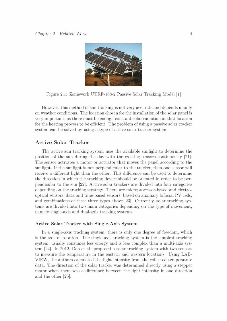
Figure 2.1: Zomework UTRF-168-2 Passive Solar Tracking Model [1]
However, this method of sun tracking is not very accurate and depends mainlyon weather conditions. The location chosen for the installation of the solar panel isvery important, as there must be enough constant solar radiation at that locationfor the heating process to be efficient. The problem of using a passive solar trackersystem can be solved by using a type of active solar tracker system.
Active Solar Tracker
The active sun tracking system uses the available sunlight to determine theposition of the sun during the day with the existing sensors continuously [21].The sensor activates a motor or actuator that moves the panel according to thesunlight. If the sunlight is not perpendicular to the tracker, then one sensor willreceive a different light than the other. This difference can be used to determinethe direction in which the tracking device should be oriented in order to be per-pendicular to the sun [22]. Active solar trackers are divided into four categoriesdepending on the tracking strategy. There are microprocessor-based and electro-optical sensors, data and time-based sensors, based on auxiliary bifacial PV cells,and combinations of these three types above [23]. Currently, solar tracking sys-tems are divided into two main categories depending on the type of movement,namely single-axis and dual-axis tracking systems.
Active Solar Tracker with Single-Axis System
In a single-axis tracking system, there is only one degree of freedom, whichis the axis of rotation. The single-axis tracking system is the simplest trackingsystem, usually consumes less energy and is less complex than a multi-axis sys-tem [24]. In 2012, Deb et al. proposed a solar tracking system with two sensorsto measure the temperature in the eastern and western locations. Using LAB-VIEW, the authors calculated the light intensity from the collected temperaturedata. The direction of the solar tracker was determined directly using a steppermotor when there was a difference between the light intensity in one directionand the other [25].
Chapter 2. Related Work 5
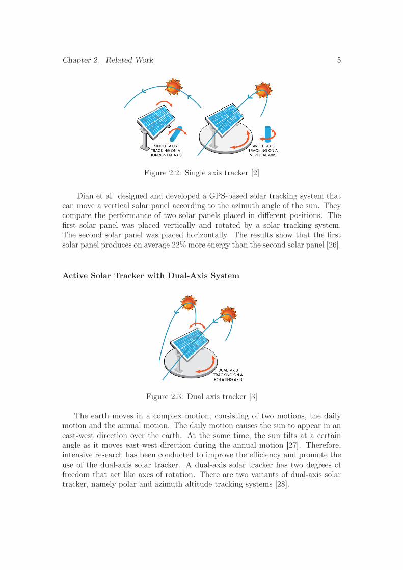
Figure 2.2: Single axis tracker [2]
Dian et al. designed and developed a GPS-based solar tracking system thatcan move a vertical solar panel according to the azimuth angle of the sun. Theycompare the performance of two solar panels placed in different positions. Thefirst solar panel was placed vertically and rotated by a solar tracking system.The second solar panel was placed horizontally. The results show that the firstsolar panel produces on average 22% more energy than the second solar panel [26].
Active Solar Tracker with Dual-Axis System
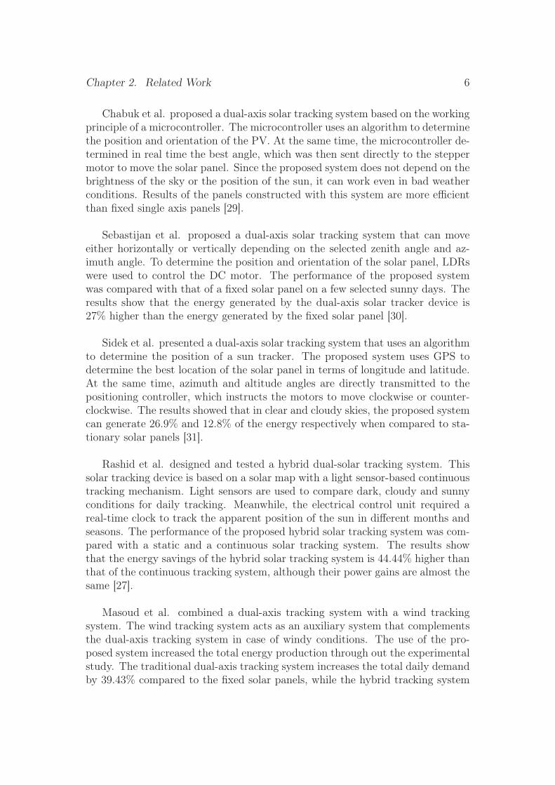
Figure 2.3: Dual axis tracker [3]
The earth moves in a complex motion, consisting of two motions, the dailymotion and the annual motion. The daily motion causes the sun to appear in aneast-west direction over the earth. At the same time, the sun tilts at a certainangle as it moves east-west direction during the annual motion [27]. Therefore,intensive research has been conducted to improve the efficiency and promote theuse of the dual-axis solar tracker. A dual-axis solar tracker has two degrees offreedom that act like axes of rotation. There are two variants of dual-axis solartracker, namely polar and azimuth altitude tracking systems [28].
Chapter 2. Related Work 6
Chabuk et al. proposed a dual-axis solar tracking system based on the workingprinciple of a microcontroller. The microcontroller uses an algorithm to determinethe position and orientation of the PV. At the same time, the microcontroller de-termined in real time the best angle, which was then sent directly to the steppermotor to move the solar panel. Since the proposed system does not depend on thebrightness of the sky or the position of the sun, it can work even in bad weatherconditions. Results of the panels constructed with this system are more efficientthan fixed single axis panels [29].
Sebastijan et al. proposed a dual-axis solar tracking system that can moveeither horizontally or vertically depending on the selected zenith angle and az-imuth angle. To determine the position and orientation of the solar panel, LDRswere used to control the DC motor. The performance of the proposed systemwas compared with that of a fixed solar panel on a few selected sunny days. Theresults show that the energy generated by the dual-axis solar tracker device is27% higher than the energy generated by the fixed solar panel [30].
Sidek et al. presented a dual-axis solar tracking system that uses an algorithmto determine the position of a sun tracker. The proposed system uses GPS todetermine the best location of the solar panel in terms of longitude and latitude.At the same time, azimuth and altitude angles are directly transmitted to thepositioning controller, which instructs the motors to move clockwise or counter-clockwise. The results showed that in clear and cloudy skies, the proposed systemcan generate 26.9% and 12.8% of the energy respectively when compared to sta-tionary solar panels [31].
Rashid et al. designed and tested a hybrid dual-solar tracking system. Thissolar tracking device is based on a solar map with a light sensor-based continuoustracking mechanism. Light sensors are used to compare dark, cloudy and sunnyconditions for daily tracking. Meanwhile, the electrical control unit required areal-time clock to track the apparent position of the sun in different months andseasons. The performance of the proposed hybrid solar tracking system was com-pared with a static and a continuous solar tracking system. The results showthat the energy savings of the hybrid solar tracking system is 44.44% higher thanthat of the continuous tracking system, although their power gains are almost thesame [27].
Masoud et al. combined a dual-axis tracking system with a wind trackingsystem. The wind tracking system acts as an auxiliary system that complementsthe dual-axis tracking system in case of windy conditions. The use of the pro-posed system increased the total energy production through out the experimentalstudy. The traditional dual-axis tracking system increases the total daily demandby 39.43% compared to the fixed solar panels, while the hybrid tracking system
Chapter 2. Related Work 7
increases the total daily demand by 49.83% [32].
Juang et al. designed and built a dual-axis solar tracking system to maximizeradiation and reduce voltage consumption. The proposed system consists of a mi-crocontroller, LDRs, actuators, Arduino Uno R3 and Pololu Dual Motor Shield.The linear actuators are adjusted when the absolute value of the calculated dif-ference is greater than the deadband value specified by the LDR. The proposedsystem guarantees a real-time response and an increase of the output power of atleast between 15%-20% [33].
Assaf has developed a dual axis solar tracking system to measure total solarradiation. The proposed system consists of four LDRs, a programmable logiccontroller (PLC) and two servo motors. As usual, the LDR has to detect the po-sition of the sun and thus transmit a voltage signal to the PLC. The Soft ComfortV6.1 software was used to develop the control software to determine the optimumposition of the PV panel during the day. The proposed solar tracking system wastested and implemented for three days. The results show that with the dualaxis solar tracking system, the total solar radiation of the dual axis solar trackingsystem was higher than the solar radiation obtained with the fixed PV system [34].
Chronological Solar Tracker
A chronological solar tracking system is a time-based tracking system where thestructure moves from at a fixed rate and angle throughout the day and in differentmonths. Therefore, the motor or actuator must rotate slowly at an average speedof one revolution per day (15° per hour) [27].
Roong and Chong, use a chronological method with a rotation angle of 15°per hour in a single-axis solar tracking system. The solar tracking system, witha total area of about 70 sq.metres, was constructed at the University TeknikalMalaysia Melaka (UTeM). The experiments were conducted over five days be-tween 8:00 and 15:00 during the day, with the solar tracker at a fixed angle of 15°per hour [35].
Samantha et al. designed a single-axis solar tracking system to maximise theefficiency of PV cells. By following the principle of chronological sun tracking,the PV panel can track the position of the sun using a motor controlled by amicrocontroller. The position of the sun is determined by the PIC18252 micro-controller is connected to the L293D motor controller, which can be used to movethe PV panel in the desired direction. The maximum solar energy intensity canbe generated when the sun rays strike the solar panel surface perpendicularly[36].
Chapter 3Method
3.1 Problem StatementSolar panels are usually fixed and do not follow the movement of the sun.
Because of this disadvantage, a solar panel can only work effectively if maximumamount of sunlight falls on it, and the amount of sunlight varies or changes ac-cording to the time of day.
As the fixed solar panel cannot be aimed directly at the sun if the earth isconstantly moving then the power produced by this device is therefore not themaximum it should be producing. The best solution to get the maximum powerfrom this system is a solar tracking system. This is the main reason for build-ing solar tracker. Solar trackers can follow the sun’s rays and get more outputpower. Indirectly, this reduces the cost of buying more solar panels. It also makesit unnecessary for the user to reposition the solar panels towards the sun manually.
3.2 ObjectiveThe aim of this project is to develop a technique that helps to achieve maxi-
mum solar energy production by optimizing the orientation of the movable solarpanel.
To achieve this objective we consider:
• Developing a tracking system that continuously tracks the light rays so thatthe incident ray is perpendicular to the solar panel.
• Developing a tracking system that maximises energy production from solarpanels.
• Development of a tracking system to control the movement of solar panelsas a function of monitored light intensity.
• Developing a tracking system based on LDRs.
8
Chapter 3. Method 9
3.3 Modelling
CAD modelling and 3D printing
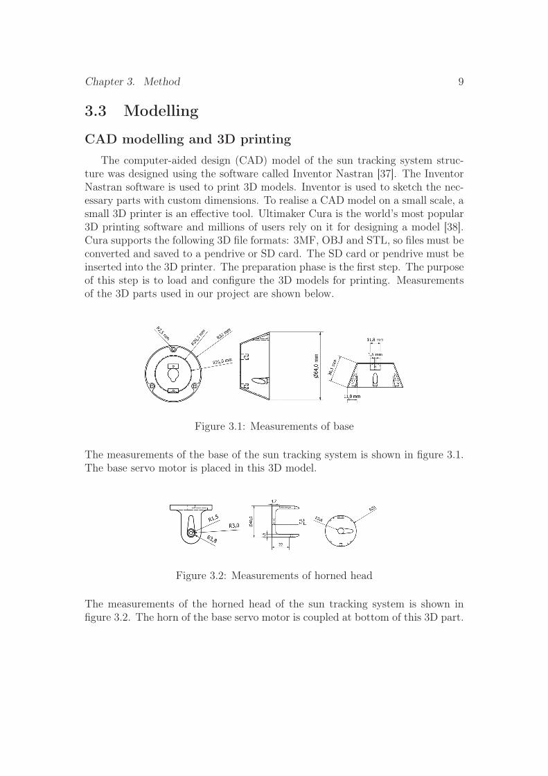
The computer-aided design (CAD) model of the sun tracking system struc-ture was designed using the software called Inventor Nastran [37]. The InventorNastran software is used to print 3D models. Inventor is used to sketch the nec-essary parts with custom dimensions. To realise a CAD model on a small scale, asmall 3D printer is an effective tool. Ultimaker Cura is the world’s most popular3D printing software and millions of users rely on it for designing a model [38].Cura supports the following 3D file formats: 3MF, OBJ and STL, so files must beconverted and saved to a pendrive or SD card. The SD card or pendrive must beinserted into the 3D printer. The preparation phase is the first step. The purposeof this step is to load and configure the 3D models for printing. Measurementsof the 3D parts used in our project are shown below.
Figure 3.1: Measurements of base
The measurements of the base of the sun tracking system is shown in figure 3.1.The base servo motor is placed in this 3D model.
Figure 3.2: Measurements of horned head
The measurements of the horned head of the sun tracking system is shown infigure 3.2. The horn of the base servo motor is coupled at bottom of this 3D part.
Chapter 3. Method 10
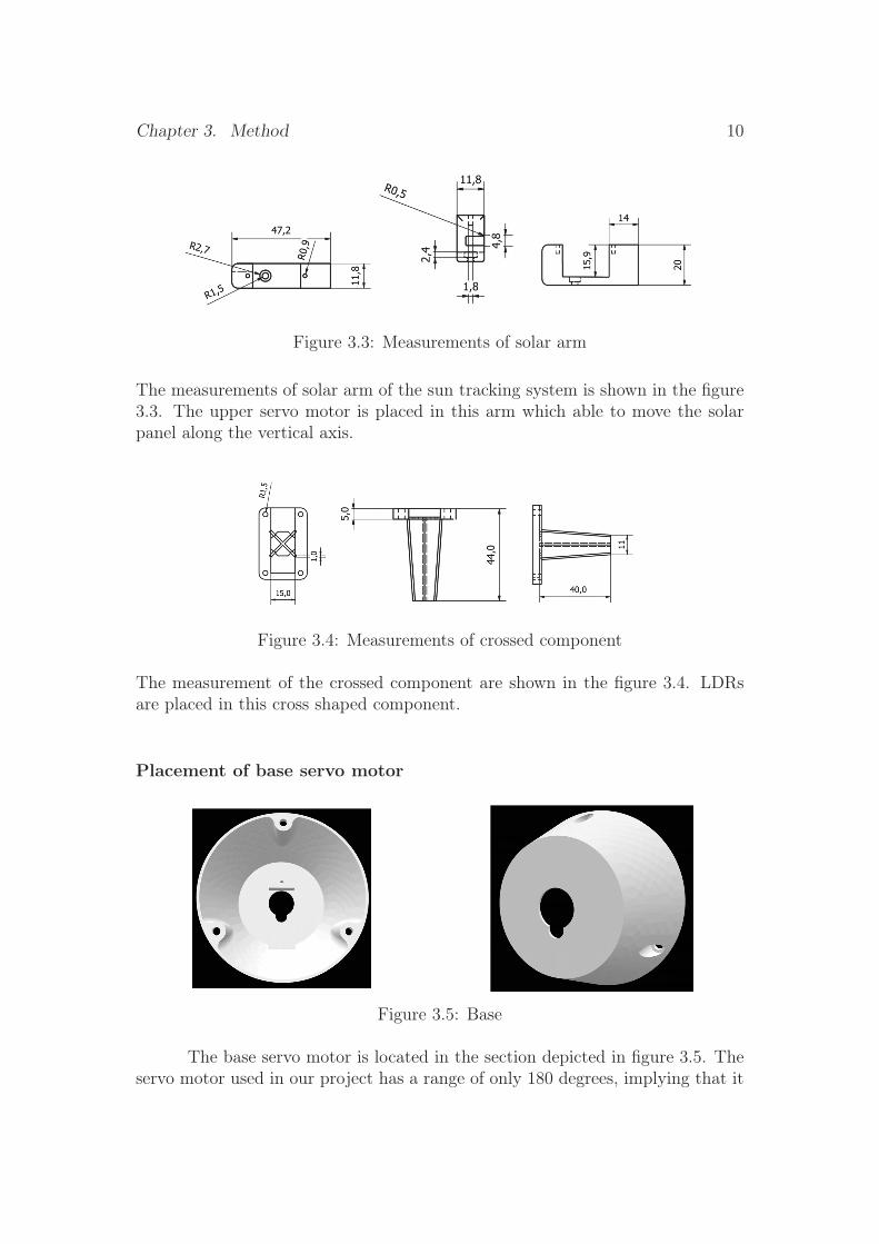
Figure 3.3: Measurements of solar arm
The measurements of solar arm of the sun tracking system is shown in the figure3.3. The upper servo motor is placed in this arm which able to move the solarpanel along the vertical axis.
Figure 3.4: Measurements of crossed component
The measurement of the crossed component are shown in the figure 3.4. LDRsare placed in this cross shaped component.
Placement of base servo motor
Figure 3.5: Base
The base servo motor is located in the section depicted in figure 3.5. Theservo motor used in our project has a range of only 180 degrees, implying that it

Chapter 3. Method 11
rotates in an east-west direction. This 3D part has an opening at the top, whichallows the axle of the base servo motor to move the upper part of the sun trackingsystem around the horizontal axis. The base part must move the entire systemso that it can be screwed to the ground in order to be inert.
Horned head
Figure 3.6: Horned head
The horned head is used to couple the axle of the base servo motor with itshorn shown in top view of figure 3.6, allowing the head to rotate around thehorizontal axis in a range of 0-180 degrees. This head serves as the link betweenthe upper and base servo motors. The axle of the upper servo motor is coupledwith its horn to the head shown in the side view of figure 3.6, allowing the solarpanel which is attached to the upper servo motor to rotate in a vertical axis in arange of 0-45 degrees.
Placement of upper servo motor
Figure 3.7: Upper servo motor’s placement
The upper servo motor is positioned in the gap between the two edges depictedin figure 3.7. This is the solar panel arm that is in charge of vertical axis rotation
Chapter 3. Method 12
in the range of 0-45 degrees. This arm is inserted into the horned head, and ascrew is inserted between the arm and the head to keep it in place.
Placement of LDRs
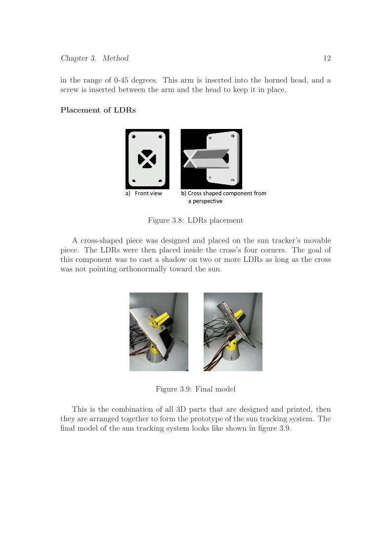
Figure 3.8: LDRs placement
A cross-shaped piece was designed and placed on the sun tracker’s movablepiece. The LDRs were then placed inside the cross’s four corners. The goal ofthis component was to cast a shadow on two or more LDRs as long as the crosswas not pointing orthonormally toward the sun.
Figure 3.9: Final model
This is the combination of all 3D parts that are designed and printed, thenthey are arranged together to form the prototype of the sun tracking system. Thefinal model of the sun tracking system looks like shown in figure 3.9.
Chapter 3. Method 13
Model
Sun tracking system is a type of solar tracker which follows or tracks the sunas it moves in the sky throughout the day and makes sure that the solar panel isdirected towards the sun’s rays to capture more light. This system is placed inan open space where the sun rays are directly fall onto it without any obstaclespresent in between.
The proposed tracking system tracks sunlight more efficiently by rotating thesolar panel along two different axes. The tracker mainly consists of four LightDependent Resistors (LDR) sensors, two micro servo motors and a microcon-troller. The north-south tilt is done by the servo motor connected at the top,while the east-west tilt is done by the servo motor connected to the bottom. Twoservo motors are used in the system. The servo motor at the top which holdsthe solar panel follows the parabolic movement of the sun, while the servo motorat the bottom follows the sun linearly. These two motors and LDR sensors areinterfaced with a microcontroller, which controls both motors based on the dataprovided by the LDRs. The LDR sensor detects the light and sends a signal tothe microcontroller. The resistance of the LDR depends on the light intensity andvaries accordingly. The higher the light intensity, the lower the LDR resistanceand the lower the output voltage. At low light levels, the LDR resistance is higherand the output voltage is higher. According to the intensity of LDRs, the upperand the lower micro servo motors are tilted towards where there is the maximumsun rays incident towards the solar panel.
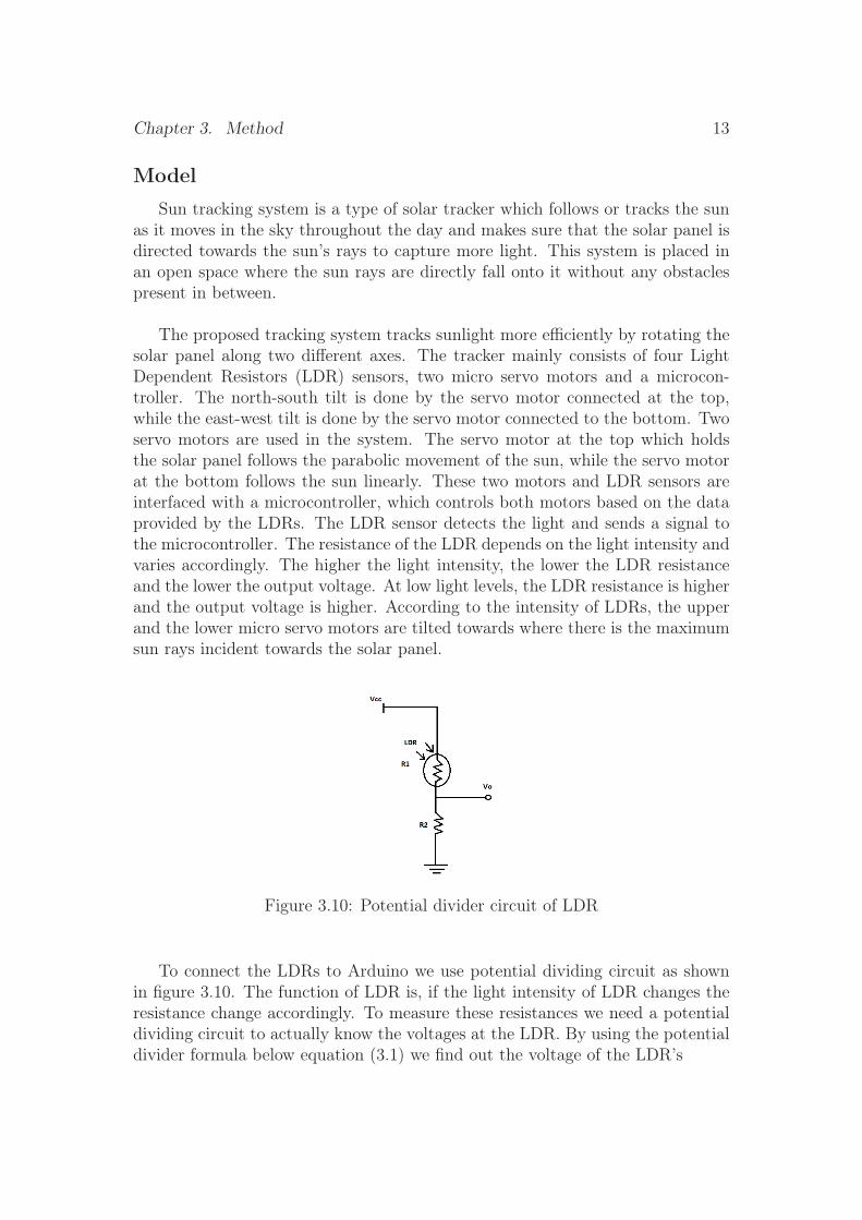
Figure 3.10: Potential divider circuit of LDR
To connect the LDRs to Arduino we use potential dividing circuit as shownin figure 3.10. The function of LDR is, if the light intensity of LDR changes theresistance change accordingly. To measure these resistances we need a potentialdividing circuit to actually know the voltages at the LDR. By using the potentialdivider formula below equation (3.1) we find out the voltage of the LDR’s
Chapter 3. Method 14
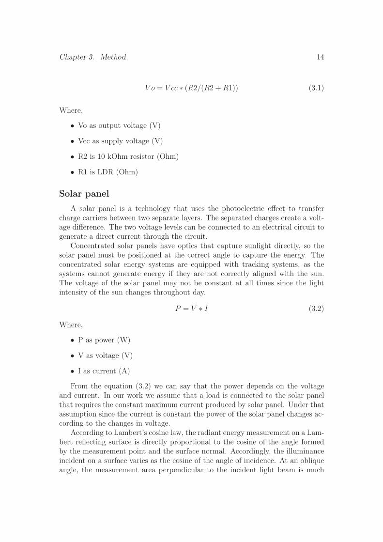
V o = V cc ∗ (R2/(R2 +R1)) (3.1)
Where,
• Vo as output voltage (V)
• Vcc as supply voltage (V)
• R2 is 10 kOhm resistor (Ohm)
• R1 is LDR (Ohm)
Solar panel
A solar panel is a technology that uses the photoelectric effect to transfercharge carriers between two separate layers. The separated charges create a volt-age difference. The two voltage levels can be connected to an electrical circuit togenerate a direct current through the circuit.
Concentrated solar panels have optics that capture sunlight directly, so thesolar panel must be positioned at the correct angle to capture the energy. Theconcentrated solar energy systems are equipped with tracking systems, as thesystems cannot generate energy if they are not correctly aligned with the sun.The voltage of the solar panel may not be constant at all times since the lightintensity of the sun changes throughout day.
P = V ∗ I (3.2)
Where,
• P as power (W)
• V as voltage (V)
• I as current (A)
From the equation (3.2) we can say that the power depends on the voltageand current. In our work we assume that a load is connected to the solar panelthat requires the constant maximum current produced by solar panel. Under thatassumption since the current is constant the power of the solar panel changes ac-cording to the changes in voltage.
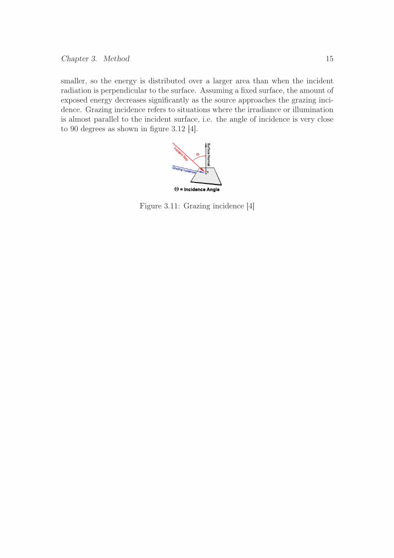
According to Lambert’s cosine law, the radiant energy measurement on a Lam-bert reflecting surface is directly proportional to the cosine of the angle formedby the measurement point and the surface normal. Accordingly, the illuminanceincident on a surface varies as the cosine of the angle of incidence. At an obliqueangle, the measurement area perpendicular to the incident light beam is much
Chapter 3. Method 15
smaller, so the energy is distributed over a larger area than when the incidentradiation is perpendicular to the surface. Assuming a fixed surface, the amount ofexposed energy decreases significantly as the source approaches the grazing inci-dence. Grazing incidence refers to situations where the irradiance or illuminationis almost parallel to the incident surface, i.e. the angle of incidence is very closeto 90 degrees as shown in figure 3.12 [4].
Figure 3.11: Grazing incidence [4]

Chapter 4Implementation
This implementation chapter mainly contains a detailed project’s descriptionof the components used in the project. This chapter consists of parts which areflowchart of sun tracking system, circuit and block diagrams, hardware and soft-ware implementation. The hardware implementation section details the hardwareand how it works in our project. In the software implementation, we focus onArduino Integrated Development Environment (IDE).
Block diagram
Figure 4.1: Block diagram of sun tracking system
Figure 4.1 represents the block diagram of the sun tracking system. As shownin the block diagram, four light-dependent resistors (LDRs) are placed on a com-
16
Chapter 4. Implementation 17
mon board with the solar panel. The light from the light source incident onthem with different intensities. Since LDRs property is photo conductivity i.e.,the resistance decreases with increasing light intensity, the resistance value of allLDRs is not always the same. Each LDR sends a corresponding signal to themicrocontroller based on their resistance values using the programming logic andthe values are compared with each other.
One of the two DC servomotors is mechanically coupled to the drive shaft ofthe other servomotor, so that the upper servomotor moves with the rotation ofthe base servomotor shaft. The shaft of the upper servomotor is used to drive thesolar panel. The two servomotors are arranged so that the solar panel can movein a north-south and east-west direction.
The microcontroller sends the appropriate signals to the servo motors accord-ing to the LDR input signals. One servo motor is used for tracking the solar panelin the north-south direction and the other motor in the east-west direction. Thepower output from solar panel will be displayed on the Liquid Crystal Display(LCD) screen. This is how the sun tracking system is designed.
4.1 Flowchart of the Sun Tracking Algorithm
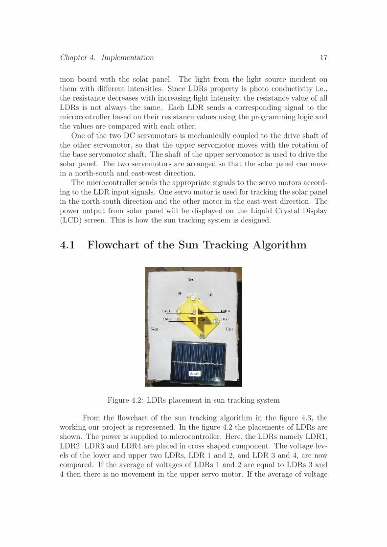
Figure 4.2: LDRs placement in sun tracking system
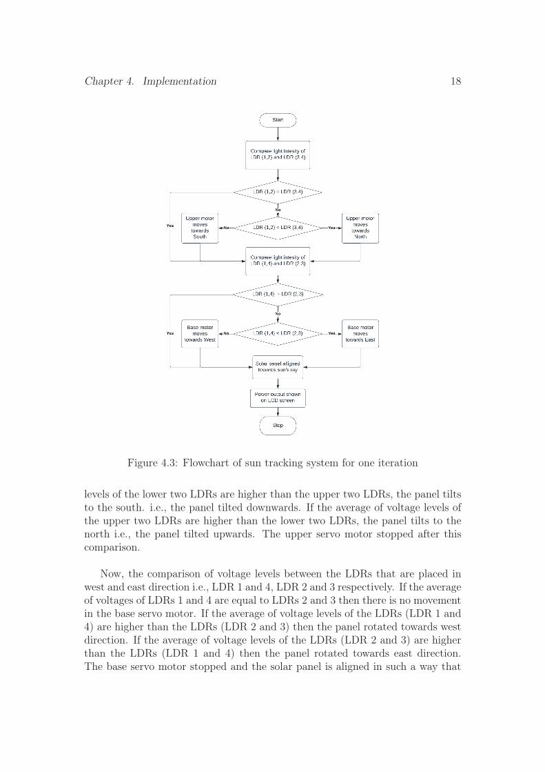
From the flowchart of the sun tracking algorithm in the figure 4.3, theworking our project is represented. In the figure 4.2 the placements of LDRs areshown. The power is supplied to microcontroller. Here, the LDRs namely LDR1,LDR2, LDR3 and LDR4 are placed in cross shaped component. The voltage lev-els of the lower and upper two LDRs, LDR 1 and 2, and LDR 3 and 4, are nowcompared. If the average of voltages of LDRs 1 and 2 are equal to LDRs 3 and4 then there is no movement in the upper servo motor. If the average of voltage
Chapter 4. Implementation 18
Figure 4.3: Flowchart of sun tracking system for one iteration
levels of the lower two LDRs are higher than the upper two LDRs, the panel tiltsto the south. i.e., the panel tilted downwards. If the average of voltage levels ofthe upper two LDRs are higher than the lower two LDRs, the panel tilts to thenorth i.e., the panel tilted upwards. The upper servo motor stopped after thiscomparison.
Now, the comparison of voltage levels between the LDRs that are placed inwest and east direction i.e., LDR 1 and 4, LDR 2 and 3 respectively. If the averageof voltages of LDRs 1 and 4 are equal to LDRs 2 and 3 then there is no movementin the base servo motor. If the average of voltage levels of the LDRs (LDR 1 and4) are higher than the LDRs (LDR 2 and 3) then the panel rotated towards westdirection. If the average of voltage levels of the LDRs (LDR 2 and 3) are higherthan the LDRs (LDR 1 and 4) then the panel rotated towards east direction.The base servo motor stopped and the solar panel is aligned in such a way that
Chapter 4. Implementation 19
the sun rays are incident onto it is perpendicular. When the optimal orientation,based on LDRs states is achieved, the solar panel capture maximum sun raysand produce maximum output power by converting the solar energy into electri-cal energy. The power output from the solar panel can be seen in the LCD display.
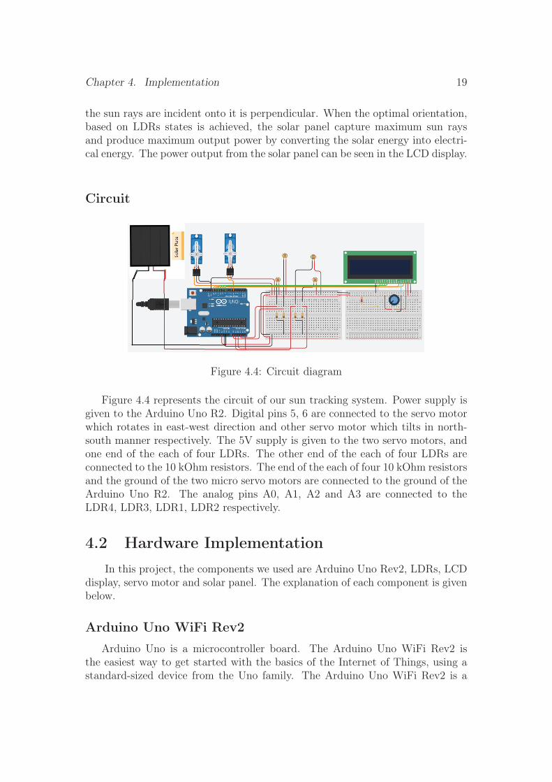
Circuit
Figure 4.4: Circuit diagram
Figure 4.4 represents the circuit of our sun tracking system. Power supply isgiven to the Arduino Uno R2. Digital pins 5, 6 are connected to the servo motorwhich rotates in east-west direction and other servo motor which tilts in north-south manner respectively. The 5V supply is given to the two servo motors, andone end of the each of four LDRs. The other end of the each of four LDRs areconnected to the 10 kOhm resistors. The end of the each of four 10 kOhm resistorsand the ground of the two micro servo motors are connected to the ground of theArduino Uno R2. The analog pins A0, A1, A2 and A3 are connected to theLDR4, LDR3, LDR1, LDR2 respectively.
4.2 Hardware ImplementationIn this project, the components we used are Arduino Uno Rev2, LDRs, LCD
display, servo motor and solar panel. The explanation of each component is givenbelow.
Arduino Uno WiFi Rev2
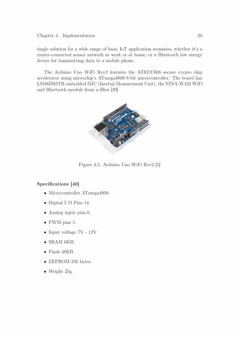
Arduino Uno is a microcontroller board. The Arduino Uno WiFi Rev2 isthe easiest way to get started with the basics of the Internet of Things, using astandard-sized device from the Uno family. The Arduino Uno WiFi Rev2 is a
Chapter 4. Implementation 20
single solution for a wide range of basic IoT application scenarios, whether it’s arouter-connected sensor network at work or at home, or a Bluetooth low energydevice for transmitting data to a mobile phone.
The Arduino Uno WiFi Rev2 features the ATECC608 secure crypto chipaccelerator using microchip’s ATmega4809 8-bit microcontroller. The board hasLSM6DS3TR embedded IMU (Inertial Measurement Unit), the NINA-W102 WiFiand Bluetooth module from u-Blox [39]
Figure 4.5: Arduino Uno WiFi Rev2 [5]
Specifications [40]
• Microcontroller ATmega4809.
• Digital I/O Pins 14.
• Analog input pins 6.
• PWM pins 5.
• Input voltage 7V - 12V.
• SRAM 6KB.
• Flash 48KB.
• EEPROM 256 bytes.
• Weight 25g.
Chapter 4. Implementation 21
Light Dependent Resistors (LDR)
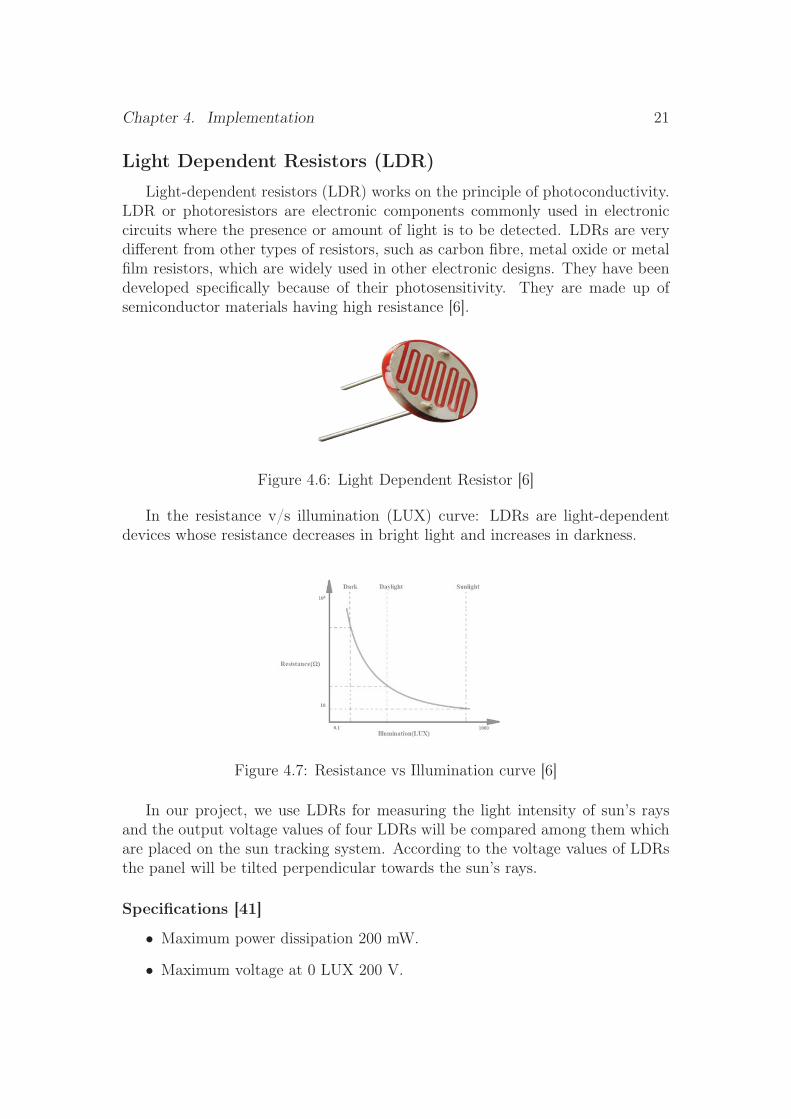
Light-dependent resistors (LDR) works on the principle of photoconductivity.LDR or photoresistors are electronic components commonly used in electroniccircuits where the presence or amount of light is to be detected. LDRs are verydifferent from other types of resistors, such as carbon fibre, metal oxide or metalfilm resistors, which are widely used in other electronic designs. They have beendeveloped specifically because of their photosensitivity. They are made up ofsemiconductor materials having high resistance [6].
Figure 4.6: Light Dependent Resistor [6]
In the resistance v/s illumination (LUX) curve: LDRs are light-dependentdevices whose resistance decreases in bright light and increases in darkness.
Figure 4.7: Resistance vs Illumination curve [6]
In our project, we use LDRs for measuring the light intensity of sun’s raysand the output voltage values of four LDRs will be compared among them whichare placed on the sun tracking system. According to the voltage values of LDRsthe panel will be tilted perpendicular towards the sun’s rays.
Specifications [41]
• Maximum power dissipation 200 mW.
• Maximum voltage at 0 LUX 200 V.
Chapter 4. Implementation 22
• Maximum resistance at 10 LUX 4.5 kOhms.
• Dark resistance 0.25 MOhms.
• Daylight resistance 5 kOhms.
LCD display
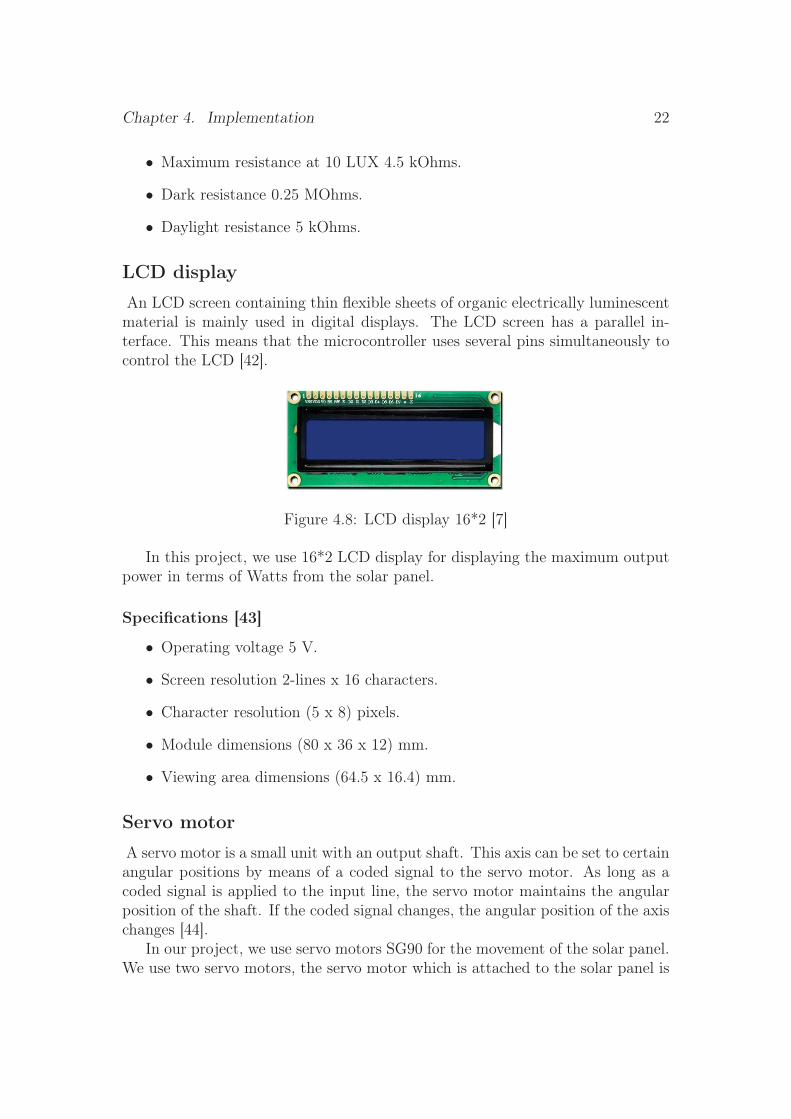
An LCD screen containing thin flexible sheets of organic electrically luminescentmaterial is mainly used in digital displays. The LCD screen has a parallel in-terface. This means that the microcontroller uses several pins simultaneously tocontrol the LCD [42].
Figure 4.8: LCD display 16*2 [7]
In this project, we use 16*2 LCD display for displaying the maximum outputpower in terms of Watts from the solar panel.
Specifications [43]
• Operating voltage 5 V.
• Screen resolution 2-lines x 16 characters.
• Character resolution (5 x 8) pixels.
• Module dimensions (80 x 36 x 12) mm.
• Viewing area dimensions (64.5 x 16.4) mm.
Servo motor
A servo motor is a small unit with an output shaft. This axis can be set to certainangular positions by means of a coded signal to the servo motor. As long as acoded signal is applied to the input line, the servo motor maintains the angularposition of the shaft. If the coded signal changes, the angular position of the axischanges [44].
In our project, we use servo motors SG90 for the movement of the solar panel.We use two servo motors, the servo motor which is attached to the solar panel is
Chapter 4. Implementation 23
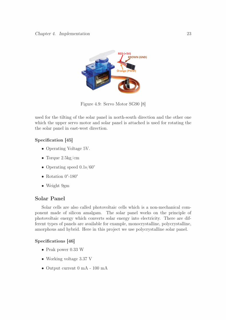
Figure 4.9: Servo Motor SG90 [8]
used for the tilting of the solar panel in north-south direction and the other onewhich the upper servo motor and solar panel is attached is used for rotating thethe solar panel in east-west direction.
Specification [45]
• Operating Voltage 5V.
• Torque 2.5kg/cm
• Operating speed 0.1s/60°
• Rotation 0°-180°
• Weight 9gm
Solar Panel
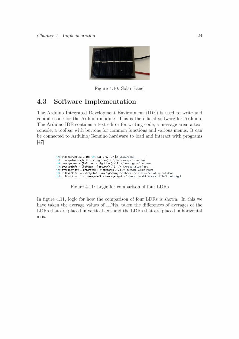
Solar cells are also called photovoltaic cells which is a non-mechanical com-ponent made of silicon amalgam. The solar panel works on the principle ofphotovoltaic energy which converts solar energy into electricity. There are dif-ferent types of panels are available for example, monocrystalline, polycrystalline,amorphous and hybrid. Here in this project we use polycrystalline solar panel.
Specifications [46]
• Peak power 0.33 W
• Working voltage 3.37 V
• Output current 0 mA - 100 mA
Chapter 4. Implementation 24
Figure 4.10: Solar Panel
4.3 Software ImplementationThe Arduino Integrated Development Environment (IDE) is used to write andcompile code for the Arduino module. This is the official software for Arduino.The Arduino IDE contains a text editor for writing code, a message area, a textconsole, a toolbar with buttons for common functions and various menus. It canbe connected to Arduino/Genuino hardware to load and interact with programs[47].
Figure 4.11: Logic for comparison of four LDRs
In figure 4.11, logic for how the comparison of four LDRs is shown. In this wehave taken the average values of LDRs, taken the differences of averages of theLDRs that are placed in vertical axis and the LDRs that are placed in horizontalaxis.
Chapter 5Results and Analysis
The prototype of sun tracking system is developed and the outcomes of oursun tracking system are reviewed and compared in the results chapter.
5.1 Performance Evaluation of the Moving Panel
Sun path diagram
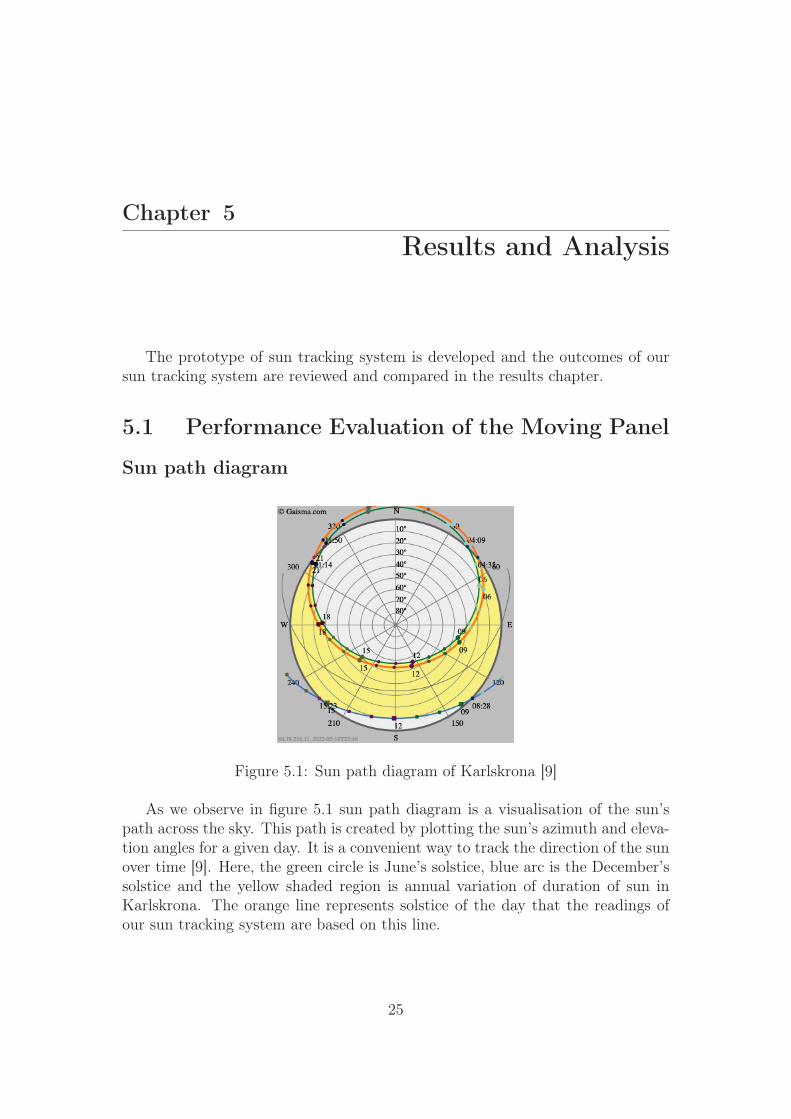
Figure 5.1: Sun path diagram of Karlskrona [9]
As we observe in figure 5.1 sun path diagram is a visualisation of the sun’spath across the sky. This path is created by plotting the sun’s azimuth and eleva-tion angles for a given day. It is a convenient way to track the direction of the sunover time [9]. Here, the green circle is June’s solstice, blue arc is the December’ssolstice and the yellow shaded region is annual variation of duration of sun inKarlskrona. The orange line represents solstice of the day that the readings ofour sun tracking system are based on this line.
25
Chapter 5. Results and Analysis 26
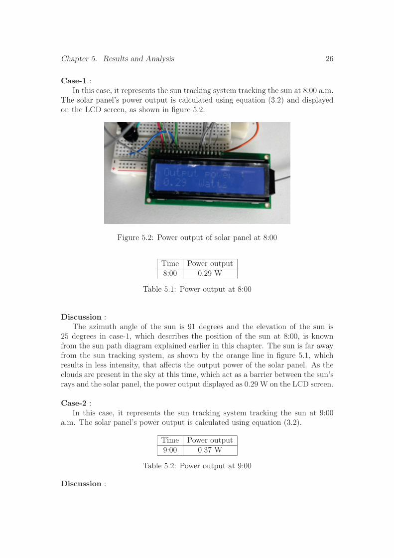
Case-1 :In this case, it represents the sun tracking system tracking the sun at 8:00 a.m.
The solar panel’s power output is calculated using equation (3.2) and displayedon the LCD screen, as shown in figure 5.2.
Figure 5.2: Power output of solar panel at 8:00
Time Power output8:00 0.29 W
Table 5.1: Power output at 8:00
Discussion :The azimuth angle of the sun is 91 degrees and the elevation of the sun is
25 degrees in case-1, which describes the position of the sun at 8:00, is knownfrom the sun path diagram explained earlier in this chapter. The sun is far awayfrom the sun tracking system, as shown by the orange line in figure 5.1, whichresults in less intensity, that affects the output power of the solar panel. As theclouds are present in the sky at this time, which act as a barrier between the sun’srays and the solar panel, the power output displayed as 0.29 W on the LCD screen.
Case-2 :In this case, it represents the sun tracking system tracking the sun at 9:00
a.m. The solar panel’s power output is calculated using equation (3.2).
Time Power output9:00 0.37 W
Table 5.2: Power output at 9:00
Discussion :
Chapter 5. Results and Analysis 27
The sun path diagram explained earlier in this chapter shows that the azimuthangle of the sun is 104 degrees and the elevation of the sun is 34 degrees in case-2,which describes the position of the sun at 9:00. When we compare the position ofthe sun at 8:00, which is shown by the orange line in figure 5.1, the sun is closerto the sun tracking system, resulting in even more intensity, which affects theoutput power of the solar panel. Since there is no obstruction of clouds betweenthe sun and the solar panel at this time, the power output is 0.37 W.
Case-3 :In this case, it represents the sun tracking system tracking the sun at 10:00
a.m. The solar panel’s power output is calculated using equation (3.2).
Time Power output10:00 0.38 W
Table 5.3: Power output at 10:00
Discussion :The sun path diagram explained earlier in this chapter shows that the azimuth
angle of the sun is 119 degrees and the elevation of the sun is 42 degrees in case-3,which describes the position of the sun at 9:00. When we compare the position ofthe sun at 9:00, which is shown by the orange line in figure 5.1, the sun is closerto the sun tracking system, resulting in even more intensity, which affects theoutput power of the solar panel. Since there is no obstruction of clouds betweenthe sun and the solar panel at this time, the power output is 0.38 W.
Case-4 :In this case, it represents the sun tracking system tracking the sun at 11:00
a.m, 12:00 and 13:00. The solar panel’s power output is calculated using equation(3.2).
Time Power output11:00 0.38 W12:00 0.3813:00 0.38
Table 5.4: Power output at 11:00, 12:00 and 13:00
Discussion :Since the temperature, sun’s intensity and the weather conditions are influ-
encing the solar panel at this time and these are also peak hours for the panel toproduce the most power. As a result, we obtained the same results as before forcase -3.

Chapter 5. Results and Analysis 28
Case-5 :In this case, it represents the sun tracking system tracking the sun at 14:00.
The solar panel’s power output is calculated using equation (3.2) and displayedon the LCD screen, as shown in figure 5.3.
Figure 5.3: Power output of solar panel at 14:00
Time Power output14:00 0.36 W
Table 5.5: Power output at 14:00
Discussion :The sun path diagram explained earlier in this chapter shows that the az-
imuth angle of the sun is 205 degrees and the elevation of the sun is 51 degrees incase-2, which describes the position of the sun at 14:00. When we compare theposition of the sun at 8:00, which is shown by the orange line in figure 5.1, thesun is closer to the sun tracking system, resulting in even more intensity, whichaffects the output power of the solar panel. Since there is no obstruction of cloudsbetween the sun and the solar panel at this time, the power output displayed onthe LCD screen as 0.36 W.
Case-6 :In this case, it represents the sun tracking system tracking the sun at 15:00.
The solar panel’s power output is calculated using equation (3.2) and displayedon the LCD screen, as shown in figure 5.4.
Time Power output15:00 0.35 W
Table 5.6: Power output at 15:00
Discussion :The sun path diagram explained earlier in this chapter shows that the az-
imuth angle of the sun is 225 degrees and the elevation of the sun is 46 degrees in

Chapter 5. Results and Analysis 29
Figure 5.4: Power output of solar panel at 15:00
case-3, which describes the position of the sun at 15:00. When we compare theposition of the sun at 14:00, which is shown by the orange line in figure 5.1, thetemperature is higher during this time due to which the output power of the solarpanel is slightly decreased [48]. As there is no obstruction between the sun and thesolar panel at this time, the power output displayed on the LCD screen as 0.35 W.
Case-7 :In this case, it represents the sun tracking system tracking the sun at 16:00.
The solar panel’s power output is calculated using equation 3.2 and displayed onthe LCD screen, as shown in figure 5.5.
Figure 5.5: Power output of solar panel at 16:00
Time Power output16:00 0.36 W
Table 5.7: Power output at 16:00
Discussion :The sun path diagram explained earlier in this chapter shows that the az-
imuth angle of the sun is 244 degrees and the elevation of the sun is 43 degrees
Chapter 5. Results and Analysis 30
in case-4, which describes the position of the sun at 16:00. When we comparethe position of the sun at 15:00, which is shown by the orange line in figure 5.1,the sun is far to the sun tracking system, which may lead to the less intensityof light and should produce less output power. But the temperature during thistime is less when compared to the case-3, that results in the increase of out-put power of the solar panel. As there is no obstruction between the sun and thesolar panel at this time, the power output displayed on the LCD screen as 0.36 W.
Case-8 :In this case, it represents the sun tracking system tracking the sun at 17:00.
The solar panel’s power output is calculated using equation 3.2 and displayed onthe LCD screen, as shown in figure 5.6.
Figure 5.6: Power output of solar panel at 17:00
Time Power output17:00 0.34 W
Table 5.8: Power output at 17:00
Discussion :The sun path diagram explained earlier in this chapter shows that the az-
imuth angle of the sun is 258 degrees and the elevation of the sun is 35 degreesin case-5, which describes the position of the sun at 17:00. When we comparethe position of the sun at 16:00, which is shown by the orange line in figure 5.1,the distance between the sun and tracking system is increased, which leads to theless intensity of light thus produced less output power. As there is no obstructionbetween the sun and the solar panel at this time, the power output displayed onthe LCD screen as 0.34 W.
Chapter 5. Results and Analysis 31
Case-9 :In this case, it represents the sun tracking system tracking the sun at 18:00.
The solar panel’s power output is calculated using equation 3.2 and displayed onthe LCD screen, as shown in figure 5.7.
Figure 5.7: Power output of solar panel at 18:00
Time Power output18:00 0.33 W
Table 5.9: Power output at 18:00
Discussion :The sun path diagram explained earlier in this chapter shows that the azimuth
angle of the sun is 271 degrees and the elevation of the sun is 27 degrees in case-6,which describes the position of the sun at 18:00. When we compare the positionof the sun at 17:00, which is shown by the orange line in figure 5.1, the distancebetween the sun and tracking system is slightly increased, which leads to the lessintensity of light thus produced marginally lesser output power. As there is noobstruction between the sun and the solar panel at this time, the power outputdisplayed on the LCD screen as 0.33 W.
Case-10 :In this case, it represents the sun tracking system tracking the sun at 19:00.
The solar panel’s power output is calculated using equation 3.2.
Time Power output19:00 0.33 W
Table 5.10: Power output at 19:00
Discussion :
Chapter 5. Results and Analysis 32
The solar panel generated the same amount of power output as in the case-9.The intensity of the sun may be same as during 18:00. Case-11 :
In this case, it represents the sun tracking system tracking the sun at 20:00.The solar panel’s power output is calculated using equation 3.2 and displayed onthe LCD screen, as shown in figure 5.8.
Figure 5.8: Power output of solar panel at 20:00
Time Power output20:00 0.21 W
Table 5.11: Power output at 20:00
Discussion :The azimuth angle of the sun is 295 degrees and the elevation of the sun is
11 degrees in case-7, which describes the position of the sun at 8:00, is knownfrom the sun path diagram explained earlier in this chapter. The sun is far awayfrom the sun tracking system, as shown by the orange line in figure 5.1, whichresults in less intensity, that affects the output power of the solar panel. As it isa cloudy sky at this time, which act as a barrier between the sun’s rays and thesolar panel, the power output displayed as 0.21 W on the LCD screen.
Chapter 5. Results and Analysis 33
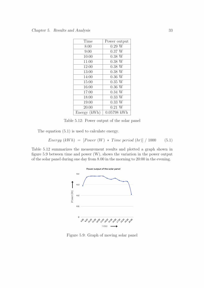
Time Power output8:00 0.29 W9:00 0.37 W10:00 0.38 W11:00 0.38 W12:00 0.38 W13:00 0.38 W14:00 0.36 W15:00 0.35 W16:00 0.36 W17:00 0.34 W18:00 0.33 W19:00 0.33 W20:00 0.21 W
Energy (kWh) 0.05798 kWh
Table 5.12: Power output of the solar panel
The equation (5.1) is used to calculate energy.
Energy (kWh) = [Power (W ) ∗ T ime period (hr)] / 1000 (5.1)
Table 5.12 summarizes the measurement results and plotted a graph shown infigure 5.9 between time and power (W), shows the variation in the power outputof the solar panel during one day from 8.00 in the morning to 20:00 in the evening.
Figure 5.9: Graph of moving solar panel

Chapter 5. Results and Analysis 34
5.2 Comparison of Power Output from Static andMoving Panels
Figure 5.10: Position of static solar and moving solar panel
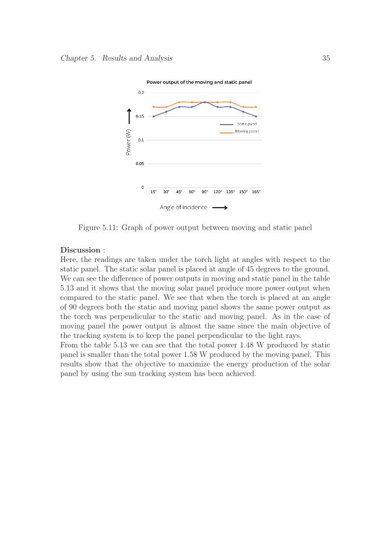
In this case, to investigate the advantage of the using sun tracker to move solarpanel we have compared the power output of fixed and the moving solar panels.To get maximum power output, solar panels in Southern Sweden are installed atan angle of about 45 degrees [49]. This result was obtained by moving the torchlight from east to west first with respect to the static panel, then with the samedistance between the torch and the panel now with respect to the moving panel,the readings were noted in table 5.13 and plotted a graph shown in figure 5.11between angle of incidence of torch and power (W), shows the variation of thepower output of the static and moving solar panels at different angle of incidenceof torch.
Angle of torch Moving Panel (W) Static panel (W)15° 0.17 W 0.15 W30° 0.17 W 0.16 W45° 0.18 W 0.17 W60° 0.18 W 0.17 W90° 0.18 W 0.18 W120° 0.18 W 0.17 W135° 0.18 W 0.17 W150° 0.17 W 0.16 W165° 0.17 W 0.15 W
Total Power 1.58 W 1.48 W
Table 5.13: Comparison of power output between static and moving panel
Chapter 5. Results and Analysis 35
Figure 5.11: Graph of power output between moving and static panel
Discussion :Here, the readings are taken under the torch light at angles with respect to thestatic panel. The static solar panel is placed at angle of 45 degrees to the ground.We can see the difference of power outputs in moving and static panel in the table5.13 and it shows that the moving solar panel produce more power output whencompared to the static panel. We see that when the torch is placed at an angleof 90 degrees both the static and moving panel shows the same power output asthe torch was perpendicular to the static and moving panel. As in the case ofmoving panel the power output is almost the same since the main objective ofthe tracking system is to keep the panel perpendicular to the light rays.From the table 5.13 we can see that the total power 1.48 W produced by staticpanel is smaller than the total power 1.58 W produced by the moving panel. Thisresults show that the objective to maximize the energy production of the solarpanel by using the sun tracking system has been achieved.
Chapter 6Conclusions and Future Work
We will conclude with a summary and future work on the sun tracking systemafter a detailed explanation of all previous chapters. In this project, we havedeveloped a prototype of sun tracking system. From this project we concludethat our system has successfully completed the main objective which is the de-veloping a tracking system that continuously tracks the light rays, developing atracking system that maximises energy production from solar panels, developinga tracking system based on LDRs, development of a tracking system to controlthe movement of solar panels as a function of monitored light intensity. Thisproject is an interesting and simple attempt to build a dual axis solar trackerusing LDRs, servo motors and a microcontroller. By this project we developeda tracking system that maximises the solar energy production by optimizing theorientation of the movable solar panel. This system works well in tracking thelight rays continuously and keeps the panel orthogonal to the light rays. Fromthe experimental results, we can say that this system has increased efficiency ascompared to the static panel. In this project, we made comparison between thestatic and moving panel and we can say that the moving panel produces moreoutput power than the static panel.
As this project is considered to be a prototype it can be developed with morerobust materials, more advanced components and more advanced algorithms totrack the sun, which would lead to an improved final product. In the future wecould use the idea of this project to implement in larger scale so that we can useit for the domestic purposes.
36
References
[1] “_USZomeworks UTRF-168-2-HD - 168 Sq. Ft Universal TrackRack.” [Online]. Available: https://www.ecodirect.com/product-p/zomeworks-utrf-168-2-hd.htm
[2] “_ENSingle Axis Trackers.” [Online]. Available: https://sinovoltaics.com/learning-center/csp/single-axis-trackers/
[3] “_ENDual Axis Trackers.” [Online]. Available: https://sinovoltaics.com/learning-center/csp/dual-axis-trackers/
[4] “Cosine Law and Surface Incidence.” [Online]. Available: http://andrewmarsh.com/blog/2010/02/01/cosine-law-and-surface-incidence/
[5] “Arduino - ArduinoBoardUno.” [Online]. Available: https://www.arduino.cc/en/main/arduinoBoardUno
[6] “Light Dependent Resistor : Circuit Diagram, Types, Work-ing & Applications.” [Online]. Available: https://www.elprocus.com/ldr-light-dependent-resistor-circuit-and-working/
[7] Xukyo, “Using a LCD16x2 Screen with Arduino • Arana-Corp,” Feb. 2020. [Online]. Available: https://www.aranacorp.com/en/using-a-lcd16x2-screen-with-arduino/
[8] “Interfacing servo motor with Arduino,” Feb. 2021. [Online]. Available:https://makersblog.in/controlling-servo-motor-with-pwm/
[9] “Karlskrona, Sweden - Sunrise, sunset, dawn and dusk times for thewhole year.” [Online]. Available: https://www.gaisma.com/en/location/karlskrona.html
[10] “Solar energy.” [Online]. Available: https://www.energimyndigheten.se/fornybart/solenergi/
[11] “solar energy - Electricity generation | Britannica.” [Online]. Available:https://www.britannica.com/science/solar-energy/Electricity-generation
37
References 38
[12] “The History of the First Solar Cell,” section: ThoughtCo. [Online].Available: https://www.thoughtco.com/history-of-solar-cells-1992435
[13] “Did You Know: Charles Fritts installed the first so-lar panels on New York City rooftop in 1884,”May 2019. [Online]. Available: https://solaredition.com/did-you-know-charles-fritts-installed-the-first-solar-panels-on-new-york-city-rooftop-in-1884/
[14] “solar tracker | technology | Britannica.” [Online]. Available: https://www.britannica.com/technology/solar-tracker
[15] R. Dhanabal, V. Bharathi, R. Ranjitha, A. Ponni, S. Deepthi, andP. Mageshkannan, “Comparison of efficiencies of solar tracker systems withstatic panel single-axis tracking system and dual-axis tracking system withfixed mount,” International journal of engineering and technology, vol. 5,no. 2, pp. 1925–1933, 2013.
[16] J. Y. Muhammad, M. T. Jimoh, I. B. Kyari, M. A. Gele, and I. Musa, “Areview on solar tracking system: A technique of solar power output enhance-ment,” Engineering Science, vol. 4, no. 1, pp. 1–11, 2019, publisher: SciencePublishing Group.
[17] M. C. Brito, J. M. Pó, D. Pereira, F. Simões, R. Rodriguez, and J. C.Amador, “Passive solar tracker based in the differential thermal expansion ofvertical strips,” Journal of Renewable and Sustainable Energy, vol. 11, no. 4,p. 043701, 2019, publisher: AIP Publishing LLC.
[18] N. J. Parmar, A. N. Parmar, and V. S. Gautam, “Passive solar trackingsystem,” International Journal of Emerging Technology and Advanced Engi-neering, vol. 5, no. 1, pp. 138–145, 2015.
[19] M. S. Sabry and B. W. Raichle, “Characteristics of residential tracker accu-racy in quantified direct beam irradiance and global horizontal irradiance,”Journal of Technology Innovations in Renewable Energy, vol. 3, no. 2, pp.44–57, 2014.
[20] “_USZomeworks UTRF-168-2-HD - 168 Sq. Ft Universal TrackRack.” [Online]. Available: https://www.ecodirect.com/product-p/zomeworks-utrf-168-2-hd.htm
[21] “A REVIEW ON SOLAR TRACKING SYSTEM | SemanticScholar.” [Online]. Available: https://www.semanticscholar.org/paper/A-REVIEW-ON-SOLAR-TRACKING-SYSTEM-Hamid-Azim/e7c504c6d1a8243757af5e8e7f91f1d77b38c6b8

References 39
[22] W. Indrasari, R. Fahdiran, E. Budi, L. Jannah, and L. V. Kadarwati, “Activesolar tracker based on the horizon coordinate system,” in Journal of Physics:Conference Series, vol. 1120. IOP Publishing, 2018, p. 012102, issue: 1.
[23] C.-C. Wei, Y.-C. Song, C.-C. Chang, and C.-B. Lin, “Design of a solar track-ing system using the brightest region in the sky image sensor,” Sensors,vol. 16, no. 12, p. 1995, 2016, publisher: Multidisciplinary Digital Publish-ing Institute.
[24] M. S. Elsherbiny, D. W. R. Anis, D. I. M. Hafez, and D. A. Mikhail, “DesignOf Single-Axis And Dual-Axis Solar Tracking Systems Protected AgainstHigh Wind Speeds,” vol. 6, no. 09, p. 6, 2017.
[25] G. Deb and A. B. Roy, “Use of solar tracking system for extracting solar en-ergy,” International Journal of Computer and Electrical Engineering, vol. 4,no. 1, p. 42, 2012, publisher: IACSIT Press.
[26] D. Artanto, A. Prasetyadi, D. Purwadianta, and R. Sambada, “Design of aGPS-based solar tracker system for a vertical solar still,” in 2016 Interna-tional Conference on Smart Green Technology in Electrical and InformationSystems (ICSGTEIS). IEEE, 2016, pp. 140–143.
[27] R. A. Ferdaus, M. A. Mohammed, S. Rahman, S. Salehin, and M. A. Man-nan, “Energy efficient hybrid dual axis solar tracking system,” Journal ofRenewable Energy, vol. 2014, 2014, publisher: Hindawi.
[28] R. Singh, S. Kumar, A. Gehlot, and R. Pachauri, “An imperative role of suntrackers in photovoltaic technology: A review,” Renewable and SustainableEnergy Reviews, vol. 82, pp. 3263–3278, 2018, publisher: Elsevier.
[29] A. Chabuk, A. Shinde, M. Narale, P. Gonjari, and P. S. Magdum, “Dual axissolar tracker using microcontroller,” Int. J. Res. Appl. Sci. Eng. Technol,vol. 4, pp. 796–800, 2017.
[30] S. Seme, G. Srpčič, D. Kavšek, S. Božičnik, T. Letnik, Z. Praunseis,B. Štumberger, and M. Hadžiselimović, “Dual-axis photovoltaic tracking sys-tem–Design and experimental investigation,” Energy, vol. 139, pp. 1267–1274, 2017, publisher: Elsevier.
[31] M. H. M. Sidek, N. Azis, W. Z. W. Hasan, M. Z. A. Ab Kadir, S. Shafie, andM. A. M. Radzi, “Automated positioning dual-axis solar tracking systemwith precision elevation and azimuth angle control,” Energy, vol. 124, pp.160–170, 2017, publisher: Elsevier.
[32] M. Rahimi, M. Banybayat, Y. Tagheie, and P. Valeh-e Sheyda, “An insighton advantage of hybrid sun–wind-tracking over sun-tracking PV system,”
References 40
Energy Conversion and Management, vol. 105, pp. 294–302, 2015, publisher:Elsevier.
[33] J.-N. Juang and R. Radharamanan, “Design of a solar tracking system forrenewable energy,” in Proceedings of the 2014 Zone 1 Conference of the Amer-ican Society for Engineering Education. IEEE, 2014, pp. 1–8.
[34] E. M. Assaf, “Design and implementation of a two axis solar tracking sys-tem using plc techniques by an inexpensive method,” International Journalof Academic Scientific Research, vol. 2, no. 3, pp. 54–65, 2014, publisher:Citeseer.
[35] A. S. C. Roong and S.-H. Chong, “Laboratory-scale single axis solar track-ing system: Design and implementation,” International Journal of PowerElectronics and Drive Systems, vol. 7, no. 1, p. 254, 2016, publisher: IAESInstitute of Advanced Engineering and Science.
[36] A. Samanta and S. Bhatt, “Chronological Single Axis Solar Tracker,” Inter-national Journal of Engineering Trends and Technology, vol. 21, no. 4, p. 4,2015.
[37] “Inventor Nastran 2022 | Download & Pricing | Autodesk.” [Online].Available: https://www.autodesk.com/products/inventor-nastran/overview
[38] “Ultimaker Cura: Powerful, easy-to-use 3D printing software.” [Online].Available: https://ultimaker.com/software/ultimaker-cura
[39] “Arduino Uno WiFi R2 - DEV-14871 - SparkFun Electronics.” [Online].Available: https://www.sparkfun.com/products/14871
[40] “UNO WiFi Rev2 | Arduino Documentation.” [Online]. Available:https://docs.arduino.cc/hardware/uno-wifi-rev2
[41] “Light Dependent Resistor : Circuit Diagram, Types, Working &Applications,” Jan. 2016. [Online]. Available: https://www.elprocus.com/ldr-light-dependent-resistor-circuit-and-working/
[42] “Arduino LCD Display - JavaTpoint.” [Online]. Available: https://www.javatpoint.com/arduino-lcd-display
[43] A. Benne, “How to Control an LCD Display with Arduino (8Examples),” Mar. 2019. [Online]. Available: https://www.makerguides.com/character-lcd-arduino-tutorial/
[44] “Arduino - Servo Motor.” [Online]. Available: https://www.tutorialspoint.com/arduino/arduino_servo_motor.htm
References 41
[45] “Servo Motor SG-90.” [Online]. Available: https://components101.com/motors/servo-motor-basics-pinout-datasheet
[46] “Köp Solcell 3V 100mA till rätt pris @ Electrokit.” [Online]. Available:https://www.electrokit.com/produkt/solcell-3v-100ma/
[47] “Software.” [Online]. Available: https://www.arduino.cc/en/software
[48] Assistant Professor, Department of Mechanical Engineering, NITTTR,Chennai and also Research Scholar , Department of MechanicalEngineering, NIT, Tiruchirappalli, Tamil Nadu, India., M. S. Kumar*,K. Balasubramanian, Associate Professor, Department of MechanicalEngineering, NIT, Tiruchirappalli, Tamil Nadu. India., L. Maheswari, andResearch Scholar, Department of Instrumentation and Control Engineering,NIT, Tiruchirappalli, Tamil Nadu. India., “Effect of Temperature on SolarPhotovoltaic Panel Efficiency,” International Journal of Engineering andAdvanced Technology, vol. 8, no. 6, pp. 2593–2595, Aug. 2019. [Online].Available: https://www.ijeat.org/portfolio-item/F8745088619/
[49] “Can I have solar panels on my roof? | Svea Solar.” [Online]. Available:https://sveasolar.comsolar-panels-on-my-roof/
Related Documents