Submittal / Substitution Request SUBMITTED TO: To: ______________________________________________________________________________ Firm: ____________________________________________________________________________ Project: __________________________________________________________________________ Submitted Product: SIMPSON STRONG-TIE ® BLUE BANGER HANGER ® ROD HANGING SYSTEM Specified Product: __________________________________________________________________ Section: ________________ Page: _______________ Detail/Sheet No.: ______________________ Description of Application: ____________________________________________________________ ________________________________________________________________________________ ________________________________________________________________________________ ________________________________________________________________________________ ________________________________________________________________________________ Attached information includes product description, installation instructions and pertinent technical data needed for evaluation of the submittal request. SUBMITTED BY: Name: ____________________________________ Signature: _____________________________ Firm: ____________________________________________________________________________ Address: _________________________________________________________________________ _________________________________________________________________________ Phone: ____________________________________ Fax: __________________________________ E-Mail: ___________________________________________________________________________ Date of Submittal: ___________________________ FOR ARCHITECT/ENGINEER USE: Approved: ______ Approved As Noted: ______ Not Approved: ______ (Please briefly explain why not approved) _________________________________________________________________________________ _________________________________________________________________________________ _________________________________________________________________________________ By: _______________________________________ Date: _________________________________ Remarks: _________________________________________________________________________ _________________________________________________________________________________ _________________________________________________________________________________ _________________________________________________________________________________ _________________________________________________________________________________ _________________________________________________________________________________ © 2011 SIMPSON STRONG-TIE COMPANY INC. T-SAS-BBHSUB11 4/11 Exp. 6/12 1

Welcome message from author
This document is posted to help you gain knowledge. Please leave a comment to let me know what you think about it! Share it to your friends and learn new things together.
Transcript

Submittal / Substitution Request
SUBMITTED TO:
To: ______________________________________________________________________________
Firm: ____________________________________________________________________________
Project: __________________________________________________________________________
Submitted Product: SIMPSON STRONG-TIE® BLUE BANGER HANGER® ROD HANGING SYSTEM
Specified Product: __________________________________________________________________
Section: ________________ Page: _______________ Detail/Sheet No.: ______________________
Description of Application: ____________________________________________________________
________________________________________________________________________________
________________________________________________________________________________
________________________________________________________________________________
________________________________________________________________________________
Attached information includes product description, installation instructions and pertinent technical data needed for evaluation of the submittal request.
SUBMITTED BY:
Name: ____________________________________ Signature: _____________________________
Firm: ____________________________________________________________________________
Address: _________________________________________________________________________
_________________________________________________________________________
Phone: ____________________________________ Fax: __________________________________
E-Mail: ___________________________________________________________________________
Date of Submittal: ___________________________
FOR ARCHITECT/ENGINEER USE:
Approved: ______ Approved As Noted: ______ Not Approved: ______
(Please briefly explain why not approved)
_________________________________________________________________________________
_________________________________________________________________________________
_________________________________________________________________________________
By: _______________________________________ Date: _________________________________
Remarks: _________________________________________________________________________
_________________________________________________________________________________
_________________________________________________________________________________
_________________________________________________________________________________
_________________________________________________________________________________
_________________________________________________________________________________
©2011 SIMPSON STRONG-TIE COMPANY INC. T-SAS-BBHSUB11 4/11 Exp. 6/12 1
T-S
AS
-BB
HS
UB
11
©2011 S
IMP
SO
N S
TR
ON
G-T
IE C
OM
PA
NY
IN
C.
Table of Contents
Simpson Strong-Tie® Blue Banger Hanger® Technical Information
Mechanical Anchors Material Safety Data Sheet
2
T-S
AS
-BB
HS
UB
11
©2011 S
IMP
SO
N S
TR
ON
G-T
IE C
OM
PA
NY
IN
C.
159
Mechanic
al A
nchors
3/4" 5/8" 1/2" 3/8" 1/4"
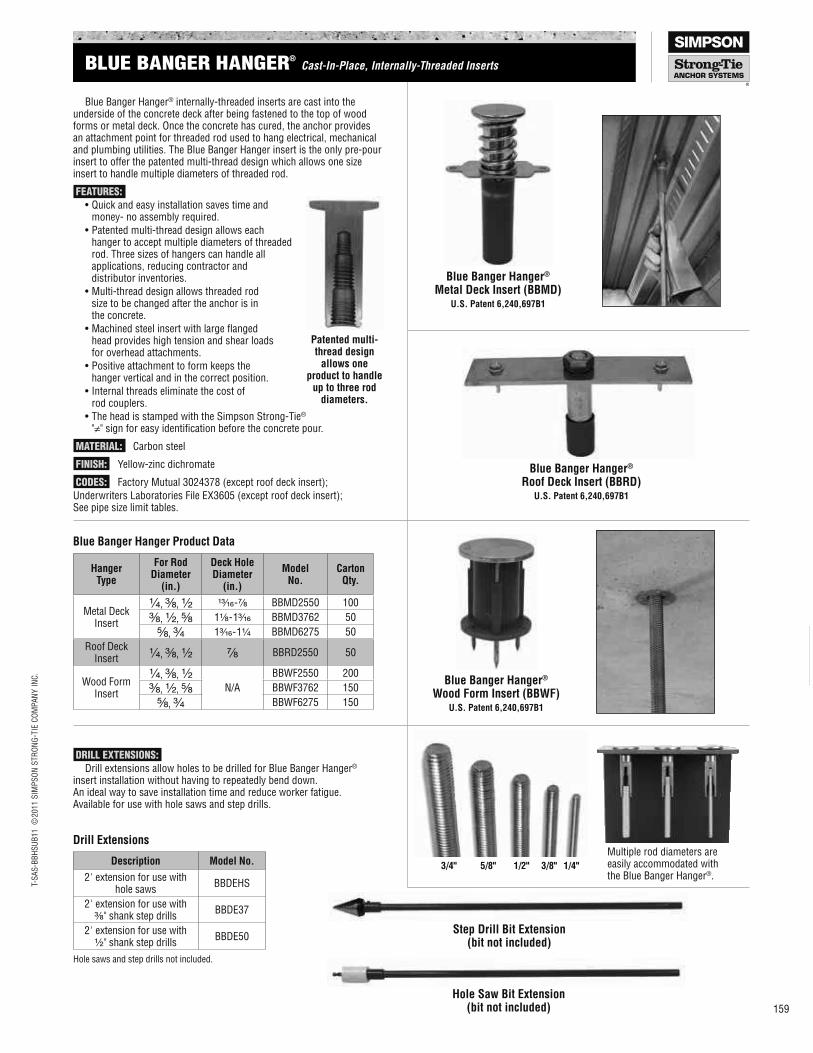
Blue Banger Hanger® internally-threaded inserts are cast into the underside of the concrete deck after being fastened to the top of wood forms or metal deck. Once the concrete has cured, the anchor provides an attachment point for threaded rod used to hang electrical, mechanical and plumbing utilities. The Blue Banger Hanger insert is the only pre-pour insert to offer the patented multi-thread design which allows one size insert to handle multiple diameters of threaded rod.
FEATURES:
•Quickandeasyinstallationsavestimeand money- no assembly required.
•Patentedmulti-threaddesignallowseach hanger to accept multiple diameters of threaded rod. Three sizes of hangers can handle all applications, reducing contractor and distributor inventories.
•Multi-threaddesignallowsthreadedrod size to be changed after the anchor is in the concrete.
•Machinedsteelinsertwithlargelanged head provides high tension and shear loads for overhead attachments.
•Positiveattachmenttoformkeepsthe hanger vertical and in the correct position.
•Internalthreadseliminatethecostof rod couplers.
•TheheadisstampedwiththeSimpsonStrong-Tie® "≠" sign for easy identification before the concrete pour.
MATERIAL: Carbon steel
FINISH: Yellow-zinc dichromate
CODES: Factory Mutual 3024378 (except roof deck insert);
Underwriters Laboratories File EX3605 (except roof deck insert); See pipe size limit tables.
Patented multi-thread design
allows one product to handle
up to three rod diameters.
Blue Banger Hanger® Roof Deck Insert (BBRD)
U.S. Patent 6,240,697B1
DRILL EXTENSIONS:
Drill extensions allow holes to be drilled for Blue Banger Hanger® insert installation without having to repeatedly bend down. An ideal way to save installation time and reduce worker fatigue. Available for use with hole saws and step drills.
Step Drill Bit Extension (bit not included)
Hole Saw Bit Extension (bit not included)
Blue Banger Hanger® Metal Deck Insert (BBMD)
U.S. Patent 6,240,697B1
Blue Banger Hanger® Wood Form Insert (BBWF)
U.S. Patent 6,240,697B1
Multiple rod diameters are easily accommodated with the Blue Banger Hanger®.
Hanger Type
For Rod Diameter
(in.)
Deck Hole Diameter
(in.)
Model No.
Carton Qty.
Metal Deck Insert
¹⁄₄, ³⁄₈, ¹⁄₂ ¹³⁄₁₆-⁷⁄₈ BBMD2550 100
³⁄₈, ¹⁄₂, ⁵⁄₈ 1¹⁄₈-1³⁄₁₆ BBMD3762 50
⁵⁄₈, ³⁄₄ 1³⁄₁₆-1¹⁄₄ BBMD6275 50
Roof Deck Insert ¹⁄₄, ³⁄₈, ¹⁄₂ ⁷⁄₈ BBRD2550 50
Wood Form Insert
¹⁄₄, ³⁄₈, ¹⁄₂
N/A
BBWF2550 200
³⁄₈, ¹⁄₂, ⁵⁄₈ BBWF3762 150
⁵⁄₈, ³⁄₄ BBWF6275 150
Blue Banger Hanger Product Data
Description Model No.
2' extension for use with hole saws
BBDEHS
2' extension for use with ³⁄₈" shank step drills
BBDE37
2' extension for use with ¹⁄₂" shank step drills
BBDE50
Hole saws and step drills not included.
Drill Extensions
BLUE BANGER HANGER®
Cast-In-Place, Internally-Threaded Inserts
T-S
AS
-BB
HS
UB
11
©2011 S
IMP
SO
N S
TR
ON
G-T
IE C
OM
PA
NY
IN
C.
160
Mechanic
al
Anchors
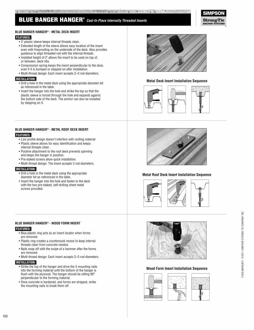
BLUE BANGER HANGER® - METAL DECK INSERT
FEATURES:
•3"plasticsleevekeepsinternalthreadsclean.
•Extendedlengthofthesleeveallowseasylocationoftheinsert even with fireproofing on the underside of the deck. Also provides guidance to align threaded rod with the internal threads.
•Installedheightof2"allowstheinserttobeusedontopof, or between, deck ribs.
•Compressionspringkeepstheinsertperpendiculartothedeck, even if it is bumped or stepped on after installation.
•Multi-threaddesign:Eachinsertaccepts2–3roddiameters.
INSTALLATION:
•Drillaholeinthemetaldeckusingtheappropriatediameterbit as referenced in the table.
•Insertthehangerintotheholeandstrikethetopsothatthe
plastic sleeve is forced through the hole and expands against the bottom side of the deck. The anchor can also be installed by stepping on it.
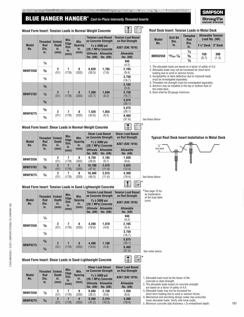
BLUE BANGER HANGER® - METAL ROOF DECK INSERT
FEATURES:
•Lowproiledesigndoesn'tinterferewithrooingmaterial
•Plasticsleeveallowsforeasyidentiicationandkeeps internal threads clean.
•Positiveattachmenttotheroofdeckpreventsspinning and keeps the hanger in position.
•Pre-stakedscrewsallowquickinstallation.
•Multi-threaddesign:Theinsertaccepts3roddiameters.
INSTALLATION:
•Drillaholeinthemetaldeckusingtheappropriate diameter bit as referenced in the table.
•Insertthehangerintotheholeandfastentothedeck with the two pre-staked, self-drilling sheet metal screws provided.
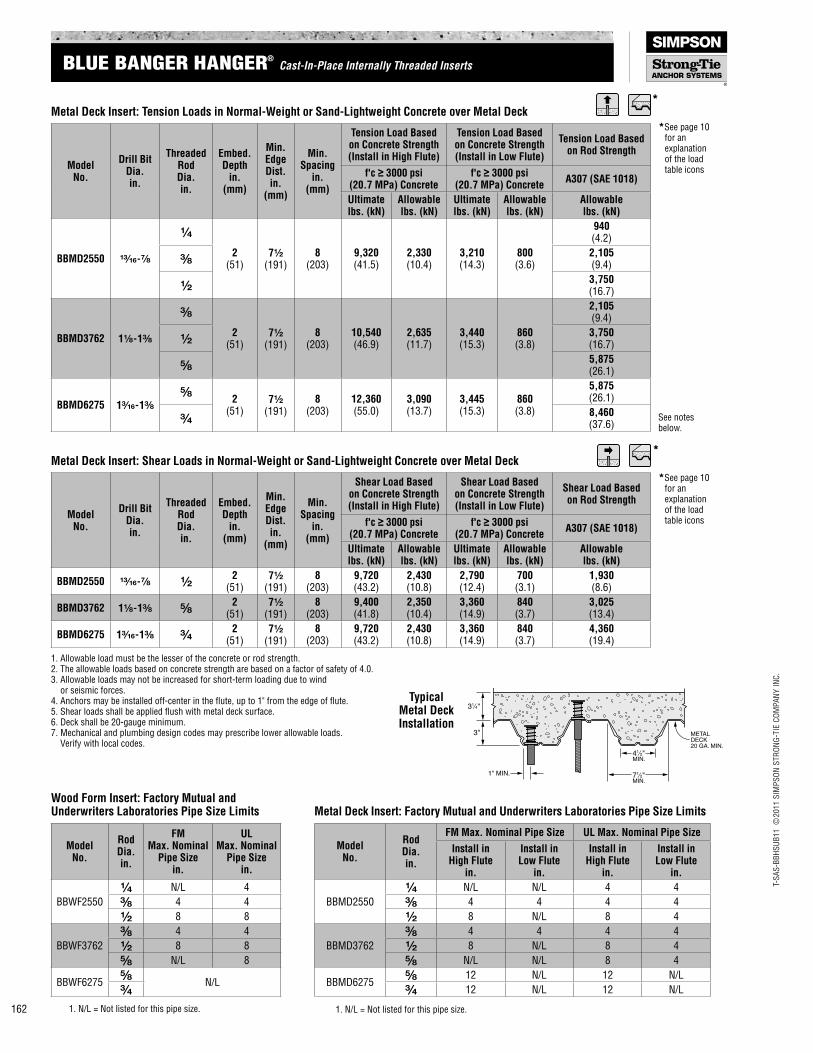
BLUE BANGER HANGER® - WOOD FORM INSERT
FEATURES:
•Blueplasticringactsasaninsertlocatorwhenforms are removed.
•Plasticringcreatesacountersunkrecesstokeepinternal threads clean from concrete residue.
•Nailssnapoffwiththeswipeofahammeraftertheforms are removed.
•Multi-threaddesign:Eachinsertaccepts2–3roddiameters.
INSTALLATION:
•Strikethetopofthehangeranddrivethe3mountingnails into the forming material until the bottom of the hanger is lushwiththeplywood.Thehangershouldbesitting90° perpendicular to the forming material.
•Onceconcreteishardened,andformsarestripped,strike the mounting nails to break them off.
Metal Deck Insert Installation Sequence
Metal Roof Deck Insert Installation Sequence
Wood Form Insert Installation Sequence
BLUE BANGER HANGER®
Cast-In-Place Internally Threaded Inserts
T-S
AS
-BB
HS
UB
11
©2011 S
IMP
SO
N S
TR
ON
G-T
IE C
OM
PA
NY
IN
C.
161
Mechanic
al A
nchors
Model No.
Drill Bit Dia. in.
Threaded Rod Dia. in.
Allowable Tension Load lbs. (kN)
1¹⁄₂" Deck 3" Deck
BBRD2550 ¹³⁄₁₆-⁷⁄₈
¹⁄₄150 (0.7)
300 (1.3)³⁄₈
¹⁄₂
1. Allowable load must be the lesser of the concrete or steel strength.2. The allowable loads based on concrete strength are based on a factor of safety of 4.0.3. Allowable loads may not be increased for short-term loading due to wind or seismic forces.4. Mechanical and plumbing design codes may prescribe lower allowable loads. Verify with local codes.5. Minimum concrete slab thickness = 2x embedment depth.
See notes below.
1. The allowable loads are based on a factor of safety of 4.0.2. Allowable loads may not be increased for short-term loading due to wind or seismic forces.3.Acceptabilityofdeckdelectionduetoimposedloads must be investigated separately.4. Threaded-rod strength must be investigated separately.5.Anchorsmaybeinstalledinthetoporbottomluteof the metal deck.6. Deck shall be 20-gauge minimum.
*
*
*
*
Model No.
Threaded Rod Dia. in.
Embed. Depth
in. (mm)
Min. Edge Dist. in.
(mm)
Min. Spacing
in. (mm)
Tension Load Based on Concrete Strength
Tension Load Based on Rod Strength
f'c ≥ 3000 psi (20.7 MPa) Concrete
A307 (SAE 1018)
Ultimate lbs. (kN)
Allowable lbs. (kN)
Allowable lbs. (kN)
BBWF2550
¹⁄₄
2 (51)
7 (178)
8 (203)
6,820 (30.3)
1,705 (7.6)
940 (4.2)
See Notes Below
³⁄₈2,105 (9.4)
¹⁄₂3,750 (16.7)
BBWF3762
³⁄₈
2 (51)
7 (178)
8 (203)
7,360 (32.7)
1,840 (8.2)
2,105 (9.4)
¹⁄₂3,750 (16.7)
⁵⁄₈5,875 (26.1)
BBWF6275⁵⁄₈
2 (51)
7 (178)
8 (203)
7,420 (33.0)
1,855 (8.3)
5,875 (26.1)
³⁄₄8,460 (37.6)
Wood Form Insert: Tension Loads in Normal-Weight Concrete Roof Deck Insert: Tension Loads in Metal Deck
Model No.
Threaded Rod Dia. in.
Embed. Depth
in. (mm)
Min. Edge Dist. in.
(mm)
Min. Spacing
in. (mm)
Shear Load Based on Concrete Strength
Shear Load Based on Rod Strength
f'c ≥ 3000 psi (20.7 MPa) Concrete
A307 (SAE 1018)
Ultimate lbs. (kN)
Allowable lbs. (kN)
Allowable lbs. (kN)
BBWF2550 ¹⁄₂2
(51)7
(178)8
(203)8,750 (38.9)
2,185 (9.7)
1,930 (8.6)
See Notes Below
BBWF3762 ⁵⁄₈2
(51)7
(178)8
(203)10,700 (47.6)
2,675 (11.9)
3,025 (13.4)
BBWF6275 ³⁄₄2
(51)7
(178)8
(203)10,460 (46.5)
2,615 (11.6)
4,360 (19.4)
Wood Form Insert: Shear Loads in Normal-Weight Concrete
Model No.
Threaded Rod Dia. in.
Embed. Depth
in. (mm)
Min. Edge Dist. in.
(mm)
Min. Spacing
in. (mm)
Tension Load Based on Concrete Strength
Tension Load Based on Rod Strength
f'c ≥ 3000 psi (20.7 MPa) Concrete
A307 (SAE 1018)
Ultimate lbs. (kN)
Allowable lbs. (kN)
Allowable lbs. (kN)
BBWF2550
¹⁄₄
2 (51)
7 (178)
8 (203)
4,280 (19.0)
1,070 (4.8)
940 (4.2)
³⁄₈2,105 (9.4)
¹⁄₂3,750 (16.7)
BBWF6275⁵⁄₈
2 (51)
7 (178)
8 (203)
4,400 (19.6)
1,100 (4.9)
5,875 (26.1)
³⁄₄8,460 (37.6)
Wood Form Insert: Tension Loads in Sand-Lightweight Concrete
Model No.
Threaded Rod Dia. in.
Embed. Depth
in. (mm)
Min. Edge Dist. in.
(mm)
Min. Spacing
in. (mm)
Shear Load Based on Concrete Strength
Shear Load Based on Rod Strength
f'c ≥ 3000 psi (20.7 MPa) Concrete
A307 (SAE 1018)
Ultimate lbs. (kN)
Allowable lbs. (kN)
Allowable lbs. (kN)
BBWF2550 ¹⁄₂2
(51)7
(178)8
(203)8,600 (38.2)
2,150 (9.6)
1,930 (8.6)
BBWF6275 ³⁄₄2
(51)7
(178)8
(203)9,260 (41.2)
2,315 (10.3)
4,360 (19.4)
Wood Form Insert: Shear Loads in Sand-Lightweight Concrete
See table
Typical Roof Deck Insert Installation in Metal Deck
*See page 10 for an explanation of the load table icons
BLUE BANGER HANGER®
Cast-In-Place Internally Threaded Inserts
T-S
AS
-BB
HS
UB
11
©2011 S
IMP
SO
N S
TR
ON
G-T
IE C
OM
PA
NY
IN
C.
162
Model No.
Drill Bit Dia. in.
Threaded Rod Dia. in.
Embed. Depth
in. (mm)
Min. Edge Dist. in.
(mm)
Min. Spacing
in. (mm)
Shear Load Based on Concrete Strength (Install in High Flute)
Shear Load Based on Concrete Strength (Install in Low Flute)
Shear Load Based on Rod Strength
f'c ≥ 3000 psi (20.7 MPa) Concrete
f'c ≥ 3000 psi (20.7 MPa) Concrete
A307 (SAE 1018)
Ultimate lbs. (kN)
Allowable lbs. (kN)
Ultimate lbs. (kN)
Allowable lbs. (kN)
Allowable lbs. (kN)
BBMD2550 ¹³⁄₁₆-⁷⁄₈ ¹⁄₂2
(51)7¹⁄₂
(191)8
(203)9,720 (43.2)
2,430 (10.8)
2,790 (12.4)
700 (3.1)
1,930 (8.6)
BBMD3762 1¹⁄₈-1³⁄₈ ⁵⁄₈2
(51)7¹⁄₂
(191)8
(203)9,400 (41.8)
2,350 (10.4)
3,360 (14.9)
840 (3.7)
3,025 (13.4)
BBMD6275 1³⁄₁₆-1³⁄₈ ³⁄₄2
(51)7¹⁄₂
(191)8
(203)9,720 (43.2)
2,430 (10.8)
3,360 (14.9)
840 (3.7)
4,360 (19.4)
Metal Deck Insert: Shear Loads in Normal-Weight or Sand-Lightweight Concrete over Metal Deck
1. Allowable load must be the lesser of the concrete or rod strength.2. The allowable loads based on concrete strength are based on a factor of safety of 4.0.3. Allowable loads may not be increased for short-term loading due to wind or seismic forces.4. Anchors may be installed off-center in the flute, up to 1" from the edge of flute.5. Shear loads shall be applied flush with metal deck surface.6. Deck shall be 20-gauge minimum.7. Mechanical and plumbing design codes may prescribe lower allowable loads. Verify with local codes.
METAL
DECK
20 GA. MIN.
71⁄2"MIN.
41⁄2"MIN.
31⁄4"
3"
1" MIN.
Typical Metal Deck Installation
See notes below.
1. N/L = Not listed for this pipe size.1. N/L = Not listed for this pipe size.
*
*
Model No.
Drill Bit Dia. in.
Threaded Rod Dia. in.
Embed. Depth
in. (mm)
Min. Edge Dist. in.
(mm)
Min. Spacing
in. (mm)
Tension Load Based on Concrete Strength (Install in High Flute)
Tension Load Based on Concrete Strength (Install in Low Flute)
Tension Load Based on Rod Strength
f'c ≥ 3000 psi (20.7 MPa) Concrete
f'c ≥ 3000 psi (20.7 MPa) Concrete
A307 (SAE 1018)
Ultimate lbs. (kN)
Allowable lbs. (kN)
Ultimate lbs. (kN)
Allowable lbs. (kN)
Allowable lbs. (kN)
BBMD2550 ¹³⁄₁₆-⁷⁄₈
¹⁄₄
2 (51)
7¹⁄₂ (191)
8 (203)
9,320 (41.5)
2,330 (10.4)
3,210 (14.3)
800 (3.6)
940 (4.2)
³⁄₈2,105 (9.4)
¹⁄₂3,750 (16.7)
BBMD3762 1¹⁄₈-1³⁄₈
³⁄₈
2 (51)
7¹⁄₂ (191)
8 (203)
10,540 (46.9)
2,635 (11.7)
3,440 (15.3)
860 (3.8)
2,105 (9.4)
¹⁄₂3,750 (16.7)
⁵⁄₈5,875 (26.1)
BBMD6275 1³⁄₁₆-1³⁄₈
⁵⁄₈2
(51)7¹⁄₂
(191)8
(203)12,360 (55.0)
3,090 (13.7)
3,445 (15.3)
860 (3.8)
5,875 (26.1)
³⁄₄8,460 (37.6)
Metal Deck Insert: Tension Loads in Normal-Weight or Sand-Lightweight Concrete over Metal Deck
Model No.
Rod Dia. in.
FM Max. Nominal
Pipe Size in.
UL Max. Nominal
Pipe Size in.
BBWF2550
¹⁄₄ N/L 4
³⁄₈ 4 4
¹⁄₂ 8 8
BBWF3762
³⁄₈ 4 4
¹⁄₂ 8 8
⁵⁄₈ N/L 8
BBWF6275⁵⁄₈
N/L³⁄₄
Wood Form Insert: Factory Mutual and Underwriters Laboratories Pipe Size Limits
Model No.
Rod Dia. in.
FM Max. Nominal Pipe Size UL Max. Nominal Pipe Size
Install in High Flute
in.
Install in Low Flute
in.
Install in High Flute
in.
Install in Low Flute
in.
BBMD2550
¹⁄₄ N/L N/L 4 4
³⁄₈ 4 4 4 4
¹⁄₂ 8 N/L 8 4
BBMD3762
³⁄₈ 4 4 4 4
¹⁄₂ 8 N/L 8 4
⁵⁄₈ N/L N/L 8 4
BBMD6275⁵⁄₈ 12 N/L 12 N/L
³⁄₄ 12 N/L 12 N/L
Metal Deck Insert: Factory Mutual and Underwriters Laboratories Pipe Size Limits
*See page 10 for an explanation of the load table icons
*See page 10 for an explanation of the load table icons
BLUE BANGER HANGER®
Cast-In-Place Internally Threaded Inserts
Anchoring and Fastening Systems for Concrete and Masonry Errata
41
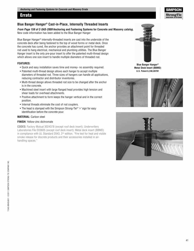
Blue Banger Hanger®
Metal Deck Insert (BBMD)
U.S. Patent 6,240,697B1
Blue Banger Hanger® Cast-in-Place, Internally Threaded Inserts
From Page 159 of C-SAS-2009 Anchoring and Fastening Systems for Concrete and Masonry catalog. New code information has been added to the Blue Banger Hanger
Blue Banger Hanger® internally-threaded inserts are cast into the underside of the concrete deck after being fastened to the top of wood forms or metal deck. Once the concrete has cured, the anchor provides an attachment point for threaded rod used to hang electrical, mechanical and plumbing utilities. The Blue Banger Hanger insert is the only pre-pour insert to offer the patented multi-thread design which allows one size insert to handle multiple diameters of threaded rod.
FEATURES:
•Quick and easy installation saves time and money- no assembly required.
•Patented multi-thread design allows each hanger to accept multiple diameters of threaded rod. Three sizes of hangers can handle all applications, reducing contractor and distributor inventories.
•Multi-thread design allows threaded rod size to be changed after the anchor is in the concrete.
•Machined steel insert with large langed head provides high tension and shear loads for overhead attachments.
•Positive attachment to form keeps the hanger vertical and in the correct position.
• Internal threads eliminate the cost of rod couplers.
•The head is stamped with the Simpson Strong-Tie® "≠" sign for easy identiication before the concrete pour.
MATERIAL: Carbon steel
FINISH: Yellow-zinc dichromate
CODES: Factory Mutual 3024378 (except roof deck insert); Underwriters Laboratories File EX3605 (except roof deck insert); Metal deck insert (BBMD) in compliance with UL Standard 2043, 2nd edition, “Fire test for heat and visible smoke release for discrete products and their accessories installed in air-handling spaces.”
Errata
T-S
AS
-BB
HS
UB
11
©2011 S
IMP
SO
N S
TR
ON
G-T
IE C
OM
PA
NY
IN
C.
T-S
AS
-BB
HS
UB
11
©2011 S
IMP
SO
N S
TR
ON
G-T
IE C
OM
PA
NY
IN
C.
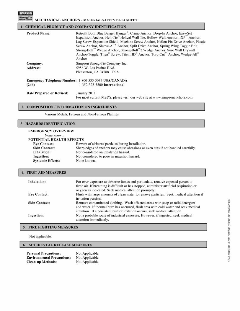
MECHANICAL ANCHORS - MATERIAL SAFETY DATA SHEET
Product Name: Retrofit Bolt, Blue Banger HangerÆ, Crimp Anchor, Drop-In Anchor, Easy-Set
Expansion Anchor, Heli-TieÆ Helical Wall Tie, Hollow Wall Anchor, IXP
™ Anchor,
Lag Screw Expansion Shield, Machine Screw Anchor, Nailon Pin Drive Anchor, Plastic
Screw Anchor, Sleeve-AllÆ Anchor, Split Drive Anchor, Spring Wing Toggle Bolt,
Strong-Bolt™
Wedge Anchor, Strong-Bolt™
2 Wedge Anchor, Sure Wall Drywall
Anchor/Toggle, TitenÆ Screw, Titen HD
Æ Anchor, Torq-Cut
™ Anchor, Wedge-All
Æ
Anchor
Company: Simpson Strong-Tie Company Inc.
Address: 5956 W. Las Positas Blvd.
Pleasanton, CA 94588 USA
Emergency Telephone Number: 1-800-535-5035 USA/CANADA
(24h) 1-352-323-3500 International
Date Prepared or Revised: January 2011
For most current MSDS, please visit our web site at www.simpsonanchors.com
Various Metals, Ferrous and Non-Ferrous Platings
EMERGENCY OVERVIEW
None known.
POTENTIAL HEALTH EFFECTS
Eye Contact: Beware of airborne particles during installation.
Skin Contact: Sharp edges of anchors may cause abrasions or even cuts if not handled carefully.
Inhalation: Not considered an inhalation hazard.
Ingestion: Not considered to pose an ingestion hazard.
Systemic Effects: None known.
Inhalation: For over-exposure to airborne fumes and particulate, remove exposed person to
fresh air. If breathing is difficult or has stopped, administer artificial respiration or
oxygen as indicated. Seek medical attention promptly.
Eye Contact: Flush with large amounts of clean water to remove particles. Seek medical attention if
irritation persists.
Skin Contact: Remove contaminated clothing. Wash affected areas with soap or mild detergent
and water. If thermal burn has occurred, flush area with cold water and seek medical
attention. If a persistent rash or irritation occurs, seek medical attention.
Ingestion: Not a probable route of industrial exposure. However, if ingested, seek medical
attention immediately.
Not applicable.
Personal Precautions: Not Applicable.
Environmental Precautions: Not Applicable.
Clean-up Methods: Not Applicable.
1. CHEMICAL PRODUCT AND COMPANY IDENTIFICATION
3. HAZARDS IDENTIFICATION
2. COMPOSITION / INFORMATION ON INGREDIENTS
5. FIRE FIGHTING MEASURES
6. ACCIDENTAL RELEASE MEASURES
4. FIRST AID MEASURES
T-S
AS
-BB
HS
UB
11
©2011 S
IMP
SO
N S
TR
ON
G-T
IE C
OM
PA
NY
IN
C.
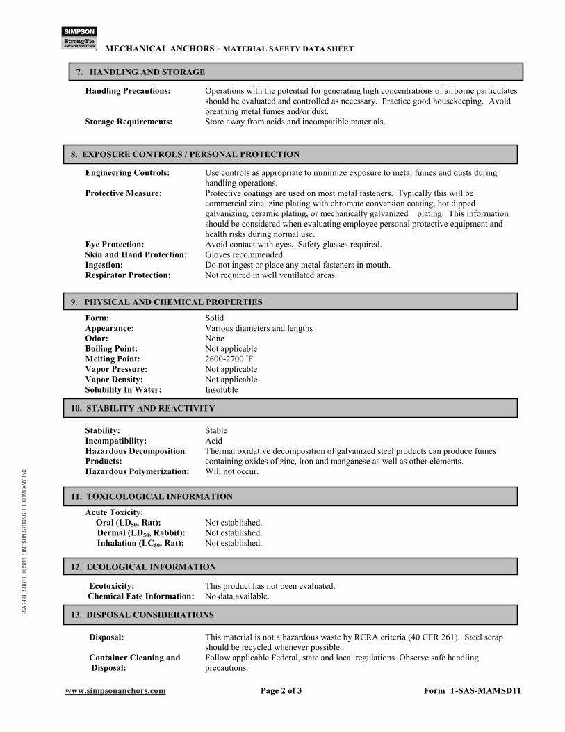
MECHANICAL ANCHORS - MATERIAL SAFETY DATA SHEET
www.simpsonanchors.com Page 2 of 3 Form T-SAS-MAMSD11
Handling Precautions: Operations with the potential for generating high concentrations of airborne particulates
should be evaluated and controlled as necessary. Practice good housekeeping. Avoid
breathing metal fumes and/or dust.
Storage Requirements: Store away from acids and incompatible materials.
Engineering Controls: Use controls as appropriate to minimize exposure to metal fumes and dusts during
handling operations.
Protective Measure: Protective coatings are used on most metal fasteners. Typically this will be
commercial zinc, zinc plating with chromate conversion coating, hot dipped
galvanizing, ceramic plating, or mechanically galvanized plating. This information
should be considered when evaluating employee personal protective equipment and
health risks during normal use.
Eye Protection: Avoid contact with eyes. Safety glasses required.
Skin and Hand Protection: Gloves recommended.
Ingestion: Do not ingest or place any metal fasteners in mouth.
Respirator Protection: Not required in well ventilated areas.
Form: Solid
Appearance: Various diameters and lengths
Odor: None
Boiling Point: Not applicable
Melting Point: 2600-2700 ゼF
Vapor Pressure: Not applicable
Vapor Density: Not applicable
Solubility In Water: Insoluble
Stability: Stable
Incompatibility: Acid
Hazardous Decomposition Thermal oxidative decomposition of galvanized steel products can produce fumes
Products: containing oxides of zinc, iron and manganese as well as other elements.
Hazardous Polymerization: Will not occur.
Acute Toxicity:
Oral (LD50, Rat): Not established.
Dermal (LD50, Rabbit): Not established.
Inhalation (LC50, Rat): Not established.
Ecotoxicity: This product has not been evaluated.
Chemical Fate Information: No data available.
Disposal: This material is not a hazardous waste by RCRA criteria (40 CFR 261). Steel scrap
should be recycled whenever possible.
Container Cleaning and Follow applicable Federal, state and local regulations. Observe safe handling
Disposal: precautions.
7. HANDLING AND STORAGE
8. EXPOSURE CONTROLS / PERSONAL PROTECTION
9. PHYSICAL AND CHEMICAL PROPERTIES
10. STABILITY AND REACTIVITY
11. TOXICOLOGICAL INFORMATION
12. ECOLOGICAL INFORMATION
13. DISPOSAL CONSIDERATIONS
T-S
AS
-BB
HS
UB
11
©2011 S
IMP
SO
N S
TR
ON
G-T
IE C
OM
PA
NY
IN
C.
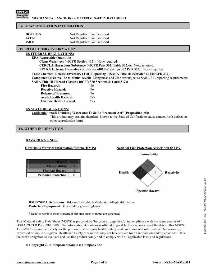
MECHANICAL ANCHORS - MATERIAL SAFETY DATA SHEET
www.simpsonanchors.com Page 3 of 3 Form T-SAS-MAMSD11
1
0
0
DOT/TDG: Not Regulated For Transport.
IATA: Not Regulated For Transport.
IMO: Not Regulated For Transport.
US FEDERAL REGULATIONS:
EPA Reportable Quantities:
Clean Water Act (40CFR Section 112): None required.
CERCLA Hazardous Substance (40CFR Part 302, Table 302.4): None required.
EPCRA Extreme Hazardous Substance (40CFR Section 302 Part 355): None required.
Toxic Chemical Release Inventory (TRI) Reporting - (SARA Title III Section 313 (40 CFR 372)
Component(s) above �de minimus� level): Manganese and Zinc are subject to SARA 313 reporting requirements.
SARA Title III Hazard Classes (40CFR 370 Sections 311 and 312):
Fire Hazard: No
Reactive Hazard: No
Release of Pressure: No
Acute Health Hazard: Yes
Chronic Health Hazard: Yes
US STATE REGULATIONS:
California - �Safe Drinking Water and Toxic Enforcement Act� (Proposition 65):
This product may contain chemicals known to the State of California to cause cancer, birth defects or
other reproductive harm.
HAZARD RATINGS:
Hazardous Material Information System (HMIS) National Fire Protection Association (NFPA)
HMIS/NFPA Definitions: 0-Least, 1-Slight, 2-Moderate, 3-High, 4-Extreme
Protective Equipment: (B) - Safety glasses, gloves
* Denotes possible chronic hazard if airborne dusts or fumes are generated.
This Material Safety Data Sheet (MSDS) is prepared by Simpson Strong-Tie Co. in compliance with the requirements of
OSHA 29 CFR Part 1910.1200. The information it contains is offered in good faith as accurate as of the date of this MSDS.
This MSDS is provided solely for the purpose of conveying health, safety, and environmental information. No warranty,
expressed or implied, is given. Health and Safety precautions may not be adequate for all individuals and/or situations. It is
the user's obligation to evaluate and use this product safely and to comply with all applicable laws and regulations.
Copyright 2011 Simpson Strong-Tie Company Inc.
Health 1*
Flammability 0
Physical Hazard 0
Personal Protection B
14. TRANSPORTATION INFORMATION
15. REGULATORY INFORMATION
16. OTHER INFORMATION
Flammability
Reactivity
Specific Hazard
Health
Related Documents