Submittal / Substitution Request © SIMPSON STRONG-TIE COMPANY INC. 1 SUBMITTED TO: To: ______________________________________________________________________________ Firm: ____________________________________________________________________________ Project: __________________________________________________________________________ Submitted Product: SIMPSON STRONG-TIE ® TITEN HD ® Heavy-Duty Screw Anchor for Cracked and Uncracked Concrete – Also suitable for masonry Products included in this submittal/substitution request: Titen HD ® Heavy-Duty Screw Anchor Titen HD ® Rod Hanger Titen HD ® Rod Coupler* Titen HD ® Mini Screw Anchor* *Not covered under a code report Specified Product: __________________________________________________________________ Section: ________________ Page: _______________ Detail/Sheet No.: ______________________ Description of Application: ____________________________________________________________ ________________________________________________________________________________ ________________________________________________________________________________ _________________________________________________________________________________ Attached information includes product description, installation instructions and pertinent technical data needed for evaluation of the submittal request. SUBMITTED BY: Name: ____________________________________ Signature: _____________________________ Firm: ____________________________________________________________________________ Address: _________________________________________________________________________ _________________________________________________________________________ Phone: ____________________________________ Fax: __________________________________ E-Mail: ___________________________________________________________________________ Date of Submittal: ___________________________ FOR ARCHITECT/ENGINEER USE: Approved: ______ Approved As Noted: ______ Not Approved: ______ (Please briefly explain why not approved) _________________________________________________________________________________ _________________________________________________________________________________ By: _______________________________________ Date: _________________________________ Remarks: _________________________________________________________________________ _________________________________________________________________________________ _________________________________________________________________________________ x x x x

Welcome message from author
This document is posted to help you gain knowledge. Please leave a comment to let me know what you think about it! Share it to your friends and learn new things together.
Transcript

Submittal / Substitution Request
© SIMPSON STRONG-TIE COMPANY INC. 1
Submitted tO:To: ______________________________________________________________________________Firm: ____________________________________________________________________________Project: __________________________________________________________________________Submitted Product: SimpSOn StrOng-tie® titen Hd® Heavy-Duty Screw Anchor for Cracked and Uncracked Concrete – Also suitable for masonryProducts included in this submittal/substitution request: Titen HD® Heavy-Duty Screw Anchor Titen HD® Rod Hanger Titen HD® Rod Coupler* Titen HD® Mini Screw Anchor* *Not covered under a code report
Specified Product: __________________________________________________________________Section: ________________ Page: _______________ Detail/Sheet No.: ______________________Description of Application: _____________________________________________________________________________________________________________________________________________________________________________________________________________________________________________________________________________________________________________
Attached information includes product description, installation instructions and pertinent technical data needed for evaluation of the submittal request.
Submitted by:Name: ____________________________________ Signature: _____________________________Firm: ____________________________________________________________________________Address: _________________________________________________________________________ _________________________________________________________________________Phone: ____________________________________ Fax: __________________________________E-Mail: ___________________________________________________________________________Date of Submittal: ___________________________
FOr ArcHitect/engineer uSe:Approved: ______ Approved As Noted: ______ Not Approved: ______(Please briefly explain why not approved)__________________________________________________________________________________________________________________________________________________________________
By: _______________________________________ Date: _________________________________Remarks: ___________________________________________________________________________________________________________________________________________________________________________________________________________________________________________
xx
xx
Table of Contents
2
This product submittal was compiled by the Simpson StrongTie Submittal Generator web app and is current as of 8/4/2015. Information included in this submittal is subject to change; see www.strongtie.com for the latest information.
Simpson StrongTie® Titen HD® HeavyDuty Screw Anchor Catalog Information Product Information Technical Information
Products included: Titen HD® HeavyDuty Screw Anchor Titen HD® Rod Coupler Titen HD® Rod Hanger Titen HD® Mini Anchor
ICCES ESR1056 (for Concrete Masonry)
City of Los Angeles Research Reports RR 25560 (for Concrete Masonry)
Factory Mutual (FM) Listing
Mechanical Anchors Safety Data Sheet
Mec
hani
cal A
ncho
rs
InstallationSequence
1⁄2" min.
TitenHD®ScrewAnchor
U.S.Patent5,674,035&6,623,228
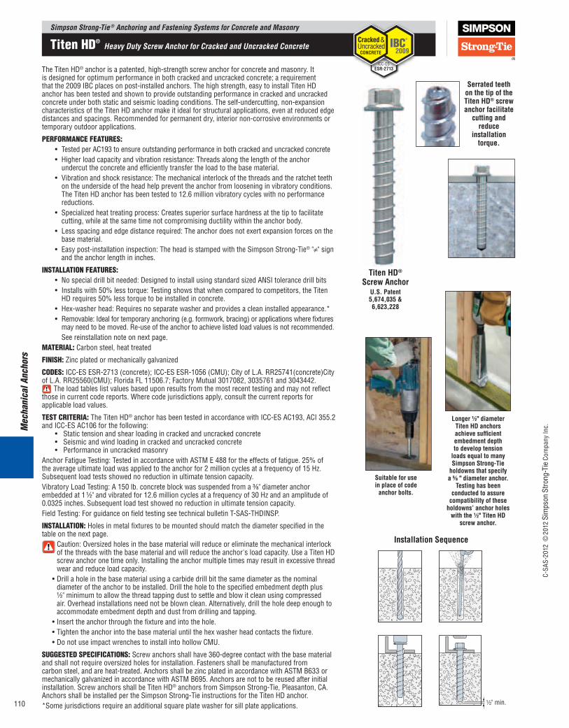
SerratedteethonthetipoftheTitenHD®screwanchorfacilitate
cuttingandreduce
installationtorque.
TheTitenHD® anchor is a patented, high-strength screw anchor for concrete and masonry. It is designed for optimum performance in both cracked and uncracked concrete; a requirement thatthe2009IBCplacesonpost-installedanchors.Thehighstrength,easytoinstallTitenHDanchor has been tested and shown to provide outstanding performance in cracked and uncracked concrete under both static and seismic loading conditions. The self-undercutting, non-expansion characteristicsoftheTitenHDanchormakeitidealforstructuralapplications,evenatreducededgedistances and spacings. Recommended for permanent dry, interior non-corrosive environments or temporary outdoor applications.
PERFORMANCE FEATURES: • TestedperAC193to ensure outstanding performance in both cracked and uncracked concrete • Higherloadcapacityandvibrationresistance:Threadsalongthelengthoftheanchor
undercut the concrete and efficiently transfer the load to the base material. • Vibrationandshockresistance:Themechanicalinterlockofthethreadsandtheratchetteeth
on the underside of the head help prevent the anchor from loosening in vibratory conditions. TheTitenHDanchorhasbeentestedto12.6millionvibratorycycleswithnoperformancereductions.
• Specializedheattreatingprocess:Createssuperiorsurfacehardnessatthetiptofacilitatecutting, while at the same time not compromising ductility within the anchor body.
• Lessspacingandedgedistancerequired:Theanchordoesnotexertexpansionforcesonthebase material.
• Easypost-installationinspection:TheheadisstampedwiththeSimpsonStrong-Tie® "≠" sign and the anchor length in inches.
iNSTAllATiON FEATURES: • Nospecialdrillbitneeded:DesignedtoinstallusingstandardsizedANSItolerancedrillbits • Installswith50%lesstorque:Testingshowsthatwhencomparedtocompetitors,theTiten
HDrequires50%lesstorquetobeinstalledinconcrete. • Hex-washerhead:Requiresnoseparatewasherandprovidesacleaninstalledappearance.* • Removable:Idealfortemporaryanchoring(e.g.formwork,bracing)orapplicationswherefixtures
may need to be moved. Re-use of the anchor to achieve listed load values is not recommended. See reinstallation note on next page.MATERiAl: Carbon steel, heat treated
FiNiSH: Zinc plated or mechanically galvanized
CODES: ICC-ES ESR-2713 (concrete); ICC-ES ESR-1056 (CMU); City of L.A. RR25741(concrete)City of L.A. RR25560(CMU); Florida FL 11506.7; Factory Mutual 3017082, 3035761 and 3043442.
Theloadtableslistvaluesbaseduponresultsfromthemostrecenttestingandmaynotreflectthose in current code reports. Where code jurisdictions apply, consult the current reports for applicable load values.
TEST CRiTERiA: TheTitenHD® anchor has been tested in accordance with ICC-ES AC193, ACI 355.2 and ICC-ES AC106 for the following: • Statictensionandshearloadingincrackedanduncrackedconcrete • Seismicandwindloadingincrackedanduncrackedconcrete • PerformanceinuncrackedmasonryAnchorFatigueTesting:TestedinaccordancewithASTME488fortheeffectsoffatigue.25%ofthe average ultimate load was applied to the anchor for 2 million cycles at a frequency of 15 Hz. Subsequent load tests showed no reduction in ultimate tension capacity. Vibratory Load Testing: A 150 lb. concrete block was suspended from a 3⁄8" diameter anchor embedded at 1 1⁄2" and vibrated for 12.6 million cycles at a frequency of 30 Hz and an amplitude of 0.0325 inches. Subsequent load test showed no reduction in ultimate tension capacity. FieldTesting:ForguidanceonfieldtestingseetechnicalbulletinT-SAS-THDINSP.
iNSTAllATiON: Holes in metal fixtures to be mounted should match the diameter specified in the table on the next page.
Caution: Oversized holes in the base material will reduce or eliminate the mechanical interlock ofthethreadswiththebasematerialandwillreducetheanchor'sloadcapacity.UseaTitenHDscrew anchor one time only. Installing the anchor multiple times may result in excessive thread wear and reduce load capacity.
•Drillaholeinthebasematerialusingacarbidedrillbitthesamediameterasthenominaldiameteroftheanchortobeinstalled.Drilltheholetothespecifiedembedmentdepthplus1⁄2" minimum to allow the thread tapping dust to settle and blow it clean using compressed air. Overhead installations need not be blown clean. Alternatively, drill the hole deep enough to accommodate embedment depth and dust from drilling and tapping.
•Insert the anchor through the fixture and into the hole.•Tighten the anchor into the base material until the hex washer head contacts the fixture.•DonotuseimpactwrenchestoinstallintohollowCMU.
SUGGESTED SPECiFiCATiONS: Screw anchors shall have 360-degree contact with the base material and shall not require oversized holes for installation. Fasteners shall be manufactured from carbon steel, and are heat-treated. Anchors shall be zinc plated in accordance with ASTM B633 or mechanically galvanized in accordance with ASTM B695. Anchors are not to be reused after initial installation.ScrewanchorsshallbeTitenHD® anchors from Simpson Strong-Tie, Pleasanton, CA. AnchorsshallbeinstalledpertheSimpsonStrong-TieinstructionsfortheTitenHDanchor.*Some jurisdictions require an additional square plate washer for sill plate applications.
Longer1⁄2"diameterTitenHDanchorsachievesufficientembedmentdepthtodeveloptensionloadsequaltomanySimpsonStrong-Tieholdownsthatspecifya5⁄8"diameteranchor.
Testinghasbeenconductedtoassurecompatibilityoftheseholdowns’anchorholeswiththe1⁄2"TitenHD
screwanchor.
Suitableforuseinplaceofcodeanchorbolts.
Simpson Strong-Tie ® Anchoring and Fastening Systems for Concrete and Masonry
C-SA
S-20
12 ©
2012
Sim
pson
Stro
ng-T
ie C
ompa
ny In
c.
110
Titen HD® Heavy Duty Screw Anchor for Cracked and Uncracked Concrete
Cracked &Uncracked CONCRETE
IBC®
2009
ESR-2713ICC-ES

Mechanical Anchors
FiXTURE HOlE DiAMETER: DuetothefullshankdiameterandlargerthreadsoftheTitenHD® screw anchor, considerationneedstobegiventospecifyingtheappropriatediameterTitenHDanchor based on the fixture hole type to be used. The American Institute of Steel Construction (AISC) has established the following guidelines with regards to fixture hole sizing depending on the hole type: •“Standard”fixtureholesare1⁄16" larger than the nominal anchor diameter. •“Oversized”fixtureholesare1⁄8 -3⁄16" larger than the nominal anchor diameter, depending upon the specific anchor diameter.
UsethefollowingtabletoidentifywhichdiameterTitenHD® screw anchor to use based on the fixture hole type and diameter. In most cases where a smaller diameter TitenHDanchoriscalledoutincomparisontothecompetitor'slargerdiameteranchor,theTitenHDanchorstillgenerallyprovidesallowabletensionandshearloadvalues comparable to or greater than those of the competitor's anchor.
TheTitenHD®screwanchor3⁄4"x6"and3⁄4"x7"(modelsTHDT75600HandTHD75700H)havea1"sectionundertheheadthatisunthreadedtoallowinstallationintotilt-upwallbraces.
OversizedfixtureholeStandardfixturehole
1⁄16" LARGERFIXTURE
ANCHOR
1⁄8" – 3⁄16"LARGER
FIXTURE
ANCHOR
Size(in.)
ModelNo.
DrillBitDia.(in.)
WrenchSize(in.)
Quantity
Box Carton3⁄8 x 3 THD37300H
3⁄8 9⁄16
50 2003⁄8 x 4 THD37400H 50 2003⁄8 x 5 THD37500H 50 1003⁄8 x 6 THD37600H 50 1001⁄2 x 3 THD50300H
1⁄2 3⁄4
25 1001⁄2 x 4 THD50400H 20 801⁄2 x 5 THD50500H 20 801⁄2 x 6 THD50600H 20 801⁄2 x 6 1⁄2 THD50612H 20 401⁄2 x 8 THD50800H 20 401⁄2 x 12 THD501200H 20 401⁄2 x 13 THD501300H 20 401⁄2 x 14 THD501400H 20 401⁄2 x 15 THD501500H 20 405⁄8 x 4 THD62400H
5⁄8 15⁄16
10 405⁄8 x 5 THD62500H 10 405⁄8 x 6 THD62600H 10 405⁄8 x 6 1⁄2 THD62612H 10 405⁄8 x 8 THD62800H 10 205⁄8 x 4 THDB62400H
5⁄8 15⁄16
10 405⁄8 x 5 THDB62500H 10 405⁄8 x 6 THDB62600H 10 405⁄8 x 6 1⁄2 THDB62612H 10 405⁄8 x 8 THDB62800H 10 203⁄4 x 4 THD75400H
3⁄4 1 1⁄8
10 403⁄4 x 5 THD75500H 5 203⁄4 x 6 THDT75600H 5 203⁄4 x 7 THD75700H 5 103⁄4 x 8 1⁄2 THD75812H 5 103⁄4 x 10 THD75100H 5 10
1. Zinc plating meets ASTM B633, SC1.2. Length is measured from the underside of the head to the tip of the anchor.
TitenHD®AnchorProductData-ZincPlated
Size(in.)
ModelNo.
DrillBitDia.(in.)
WrenchSize(in.)
Quantity
Box Carton3⁄8 x 5 THD37500HMG 3⁄8 9⁄16
50 1003⁄8 x 6 THD37600HMG 50 1001⁄2 x 5 THD50500HMG
1⁄2 3⁄4
20 801⁄2 x 6 THD50600HMG 20 801⁄2 x 6 1⁄2 THD50612HMG 20 401⁄2 x 8 THD50800HMG 20 405⁄8 x 5 THD62500HMG
5⁄8 15⁄16
10 405⁄8 x 6 THD62600HMG 10 405⁄8 x 6 1⁄2 THD62612HMG 10 405⁄8 x 8 THD62800HMG 10 205⁄8 x 5 THDB62500HMG
5⁄8 15⁄16
10 405⁄8 x 6 THDB62600HMG 10 405⁄8 x 6 1⁄2 THDB62612HMG 10 405⁄8 x 8 THDB62800HMG 10 203⁄4 x 8 1⁄2 THD75812HMG 3⁄4 1 1⁄8 5 103⁄4 x 10 THD75100HMG 5 10
1. Mechanical galvanizing meets ASTM B695, Class 65, Type 1. Intended for some pressure-treated wood sill plate applications. Not for use in other corrosive or outdoor environments. See page 11 or visit www.strongtie.com/info for more corrosion information.
TitenHDAnchorProductData-MechanicallyGalvanized
TitenHDDiameter(in.)
WrenchSize(in.)
RecommendedFixture
HoleSize(in.)
3⁄8 9⁄16 1⁄2 to 9⁄16
1⁄2 3⁄4 5⁄8 to 11⁄16
5⁄8 15⁄16 3⁄4 to 13⁄16
3⁄4 1 1⁄8 7⁄8 to 15⁄16
HoleDimensions
Simpson Strong-Tie ® Anchoring and Fastening Systems for Concrete and MasonryC-
SAS-
2012
©20
12 S
imps
on S
trong
-Tie
Com
pany
Inc.
111
Titen HD® Heavy Duty Screw Anchor for Cracked and Uncracked Concrete
Mec
hani
cal A
ncho
rs
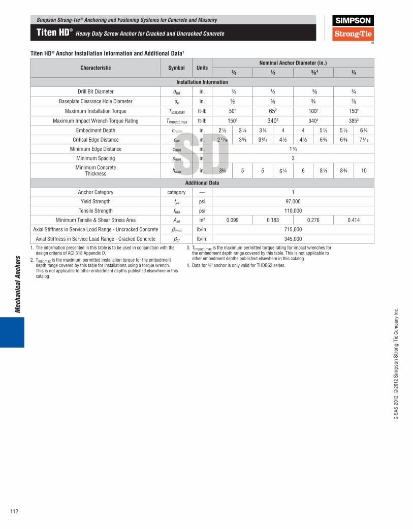
TitenHD®AnchorInstallationInformationandAdditionalData1
Characteristic Symbol UnitsNominalAnchorDiameter(in.)
3⁄8 1⁄2 5⁄84 3⁄4InstallationInformation
DrillBitDiameter dbit in. 3⁄8 1⁄2 5⁄8 3⁄4
BaseplateClearanceHoleDiameter dc in. 1⁄2 5⁄8 3⁄4 7⁄8
Maximum Installation Torque Tinst,max ft-lb 502 652 1002 1502
Maximum Impact Wrench Torque Rating Timpact,max ft-lb 1503 3403 3403 3853
EmbedmentDepth hnom in. 2 1⁄2 3 1⁄4 3 1⁄4 4 4 5 1⁄2 5 1⁄2 6 1⁄4
CriticalEdgeDistance cac in. 2 11⁄16 3 5⁄8 3 9⁄16 4 1⁄2 4 1⁄2 6 3⁄8 6 3⁄8 7 5⁄16
MinimumEdgeDistance cmin in. 1 3⁄4
Minimum Spacing smin in. 3
Minimum ConcreteThickness hmin in. 33⁄4 5 5 6 1⁄4 6 8 1⁄2 8 3⁄4 10
AdditionalData
Anchor Category category — 1
Yield Strength fya psi 97,000
Tensile Strength futa psi 110,000
Minimum Tensile & Shear Stress Area Ase in2 0.099 0.183 0.276 0.414
Axial Stiffness in Service Load Range - Uncracked Concrete βuncr lb/in. 715,000
Axial Stiffness in Service Load Range - Cracked Concrete βcr lb/in. 345,000
1. The information presented in this table is to be used in conjunction with the designcriteriaofACI318AppendixD.
2. Tinst,max is the maximum permitted installation torque for the embedment depth range covered by this table for installations using a torque wrench. This is not applicable to other embedment depths published elsewhere in this catalog.
3. Timpact,max is the maximum permitted torque rating for impact wrenches for the embedment depth range covered by this table. This is not applicable to other embedment depths published elsewhere in this catalog.
4. Datafor5⁄8"anchorisonlyvalidforTHDB62series.
Simpson Strong-Tie ® Anchoring and Fastening Systems for Concrete and Masonry
C-SA
S-20
12 ©
2012
Sim
pson
Stro
ng-T
ie C
ompa
ny In
c.
112
Titen HD® Heavy Duty Screw Anchor for Cracked and Uncracked Concrete
Mechanical Anchors
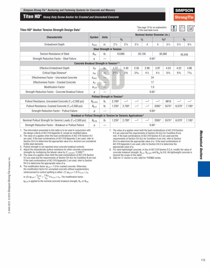
TitenHD®AnchorTensionStrengthDesignData1
Characteristic Symbol UnitsNominalAnchorDiameter(in.)
3⁄8 1⁄2 5⁄89 3⁄4EmbedmentDepth hnom in. 2 1⁄2 3 1⁄4 3 1⁄4 4 4 5 1⁄2 5 1⁄2 6 1⁄4
SteelStrengthinTension
Tension Resistance of Steel Nsa lb. 10,890 20,130 30,360 45,540Strength Reduction Factor - Steel Failure ϕ — 0.652
ConcreteBreakoutStrengthinTension6,8
EffectiveEmbedmentDepth hef in. 1.77 2.40 2.35 2.99 2.97 4.24 4.22 4.86
CriticalEdgeDistance6 cac in. 2 11⁄16 3 5⁄8 3 9⁄16 4 1⁄2 4 1⁄2 6 3⁄8 6 3⁄8 7 5⁄16
Effectiveness Factor - Uncracked Concrete kuncr — 24
Effectiveness Factor - Cracked Concrete kcr — 17
Modification Factor ψc,N — 1.0
Strength Reduction Factor - Concrete Breakout Failure ϕ — 0.657
PulloutStrengthinTension8
Pullout Resistance, Uncracked Concrete (f'c=2,500 psi) Np,uncr lb. 2,7004 —3 —3 —3 —3 9810 —3 —3
Pullout Resistance, Cracked Concrete (f'c=2,500 psi) Np,cr lb. 1,2354 2,7004 —3 —3 3260 4 5570 4 6,0704 7,1954
Strength Reduction Factor - Pullout Failure ϕ — 0.655
BreakoutorPulloutStrengthinTensionforSeismicApplications8
Nominal Pullout Strength for Seismic Loads (f'c=2,500 psi) Np,eq lb. 1,2354 2,7004 —3 —3 3260 4 5570 4 6,0704 7,1954
Strength Reduction Factor - Breakout or Pullout Failure ϕ — 0.655
1. The information presented in this table is to be used in conjunction with thedesigncriteriaofACI318AppendixD,exceptasmodifiedbelow.
2. The value of ϕ applies when the load combinations of ACI 318 Section 9.2 are used. If the load combinations of ACI 318 Appendix C are used, refer to SectionD4.5todeterminetheappropriatevalueofϕ. Anchors are considered brittle steel elements.
3. Pullout strength is not reported since concrete breakout controls.4. Adjust the characteristic pullout resistance for other concrete compressive
strengths by multiplying the tabular value by (f'c,specified / 2,500)0.5.5. The value of ϕ applies when both the load combinations of ACI 318 Section
9.2areusedandtherequirementsofSectionD4.4(c)forConditionBaremet. If the load combinations of ACI 318 Appendix C are used, refer to Section D4.5todeterminetheappropriatevalueofϕ.
6. The modification factor ψcp,N = 1.0 for cracked concrete. Otherwise, the modification factor for uncracked concrete without supplementary reinforcement to control splitting is either: (1) ψcp,N = 1.0 if ca,min ≥ cac
or (2) ψcp,N = Ca,min
Cac ≥
1.5hefCac
if ca,min < cac. The modification factor,
ψcp,N is applied to the nominal concrete breakout strength, Ncb or Ncbg.
7. The value of ϕ applies when both the load combinations of ACI 318 Section 9.2areusedandtherequirementsofSectionD4.4(c)forConditionBare met. If the load combinations of ACI 318 Section 9.2 are used and the requirementsofSectionD4.4(c)forConditionAaremet,refertoSection D4.4todeterminetheappropriatevalueofϕ. If the load combinations of ACI318AppendixCareused,refertoSectionD4.5todeterminethe appropriate value of ϕ.
8.Forsand-lightweightconcrete,inlieuofACI318SectionD.3.4,modifythevalueofconcrete breakout strength, Np,cr, Np,uncr and Neq by 0.6. All-lightweight concrete is beyond the scope of this table..
9.Datafor5⁄8"anchorisonlyvalidforTHDB62series.
**See page 13 for an explanation of the load table icons
Simpson Strong-Tie ® Anchoring and Fastening Systems for Concrete and MasonryC-
SAS-
2012
©20
12 S
imps
on S
trong
-Tie
Com
pany
Inc.
113
Titen HD® Heavy Duty Screw Anchor for Cracked and Uncracked Concrete
Mec
hani
cal A
ncho
rs
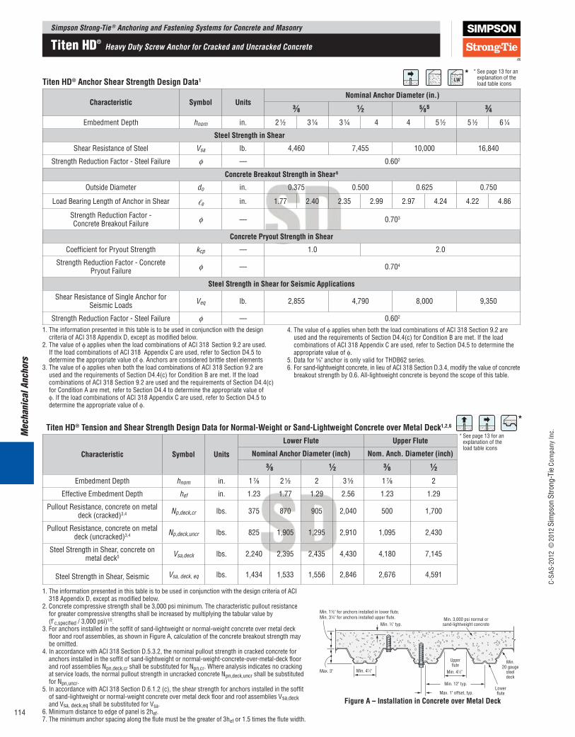
TitenHD®AnchorShearStrengthDesignData1
Characteristic Symbol UnitsNominalAnchorDiameter(in.)
3⁄8 1⁄2 5⁄85 3⁄4EmbedmentDepth hnom in. 2 1⁄2 3 1⁄4 3 1⁄4 4 4 5 1⁄2 5 1⁄2 6 1⁄4
SteelStrengthinShear
Shear Resistance of Steel Vsa lb. 4,460 7,455 10,000 16,840
Strength Reduction Factor - Steel Failure ϕ — 0.602
ConcreteBreakoutStrengthinShear6
OutsideDiameter do in. 0.375 0.500 0.625 0.750
Load Bearing Length of Anchor in Shear ℓe in. 1.77 2.40 2.35 2.99 2.97 4.24 4.22 4.86
Strength Reduction Factor -Concrete Breakout Failure ϕ — 0.703
ConcretePryoutStrengthinShear
Coefficient for Pryout Strength kcp — 1.0 2.0
Strength Reduction Factor - Concrete Pryout Failure ϕ — 0.704
SteelStrengthinShearforSeismicApplications
Shear Resistance of Single Anchor for Seismic Loads Veq lb. 2,855 4,790 8,000 9,350
Strength Reduction Factor - Steel Failure ϕ — 0.602
1. The information presented in this table is to be used in conjunction with the design criteriaofACI318AppendixD,exceptasmodifiedbelow.
2. The value of ϕ applies when the load combinations of ACI 318 Section 9.2 are used. IftheloadcombinationsofACI318AppendixCareused,refertoSectionD4.5todetermine the appropriate value of ϕ. Anchors are considered brittle steel elements
3. The value of ϕ applies when both the load combinations of ACI 318 Section 9.2 are usedandtherequirementsofSectionD4.4(c)forConditionBaremet.IftheloadcombinationsofACI318Section9.2areusedandtherequirementsofSectionD4.4(c)forConditionAaremet,refertoSectionD4.4todeterminetheappropriatevalueofϕ.IftheloadcombinationsofACI318AppendixCareused,refertoSectionD4.5todetermine the appropriate value of ϕ.
4. The value of ϕ applies when both the load combinations of ACI 318 Section 9.2 are usedandtherequirementsofSectionD4.4(c)forConditionBaremet.IftheloadcombinationsofACI318AppendixCareused,refertoSectionD4.5todeterminetheappropriate value of ϕ.
5.Datafor5⁄8"anchorisonlyvalidforTHDB62series.6.Forsand-lightweightconcrete,inlieuofACI318SectionD.3.4,modifythevalueofconcrete
breakout strength by 0.6. All-lightweight concrete is beyond the scope of this table.
TitenHD®TensionandShearStrengthDesignDataforNormal-WeightorSand-LightweightConcreteoverMetalDeck1,2,6
Characteristic Symbol Units
LowerFlute UpperFlute
NominalAnchorDiameter(inch) Nom.Anch.Diameter(inch)3⁄8 1⁄2 3⁄8 1⁄2
EmbedmentDepth hnom in. 1 7⁄8 2 1⁄2 2 3 1⁄2 1 7⁄8 2
EffectiveEmbedmentDepth hef in. 1.23 1.77 1.29 2.56 1.23 1.29
Pullout Resistance, concrete on metal deck (cracked)3,4 Np,deck,cr lbs. 375 870 905 2,040 500 1,700
Pullout Resistance, concrete on metal deck (uncracked)3,4 Np,deck,uncr lbs. 825 1,905 1,295 2,910 1,095 2,430
Steel Strength in Shear, concrete on metal deck5 Vsa,deck lbs. 2,240 2,395 2,435 4,430 4,180 7,145
Steel Strength in Shear, Seismic Vsa, deck, eq lbs. 1,434 1,533 1,556 2,846 2,676 4,591
Min. 3,000 psi normal orsand-lightweight concrete
Min.20 gauge
steeldeck
Lowerflute
Upperflute
Min. 12" typ.
Max. 1" offset, typ.
Max. 3" Min. 41⁄2"
Min. 3⁄4" typ.
Min. 41⁄2"
Min. 1½" for anchors installed in lower flute.Min. 3¼" for anchors installed upper flute.
1. The information presented in this table is to be used in conjunction with the design criteria of ACI 318AppendixD,exceptasmodifiedbelow.
2. Concrete compressive strength shall be 3,000 psi minimum. The characteristic pullout resistance for greater compressive strengths shall be increased by multiplying the tabular value by (f'c,specified / 3,000 psi)1/2.
3. For anchors installed in the soffit of sand-lightweight or normal-weight concrete over metal deck floor and roof assemblies, as shown in Figure A, calculation of the concrete breakout strength may be omitted.
4.InaccordancewithACI318SectionD.5.3.2,thenominalpulloutstrengthincrackedconcreteforanchors installed in the soffit of sand-lightweight or normal-weight-concrete-over-metal-deck floor and roof assemblies Npn,deck,cr shall be substituted for Npn,cr. Where analysis indicates no cracking at service loads, the normal pullout strength in uncracked concrete Npn,deck,uncr shall be substituted for Npn,uncr.
5.InaccordancewithACI318SectionD.6.1.2(c),theshearstrengthforanchorsinstalledinthesoffitof sand-lightweight or normal-weight concrete over metal deck floor and roof assemblies Vsa,deck and Vsa, deck,eq shall be substituted for Vsa.
6. Minimum distance to edge of panel is 2hef.7. The minimum anchor spacing along the flute must be the greater of 3hef or 1.5 times the flute width.
FigureA–InstallationinConcreteoverMetalDeck
*
*
* See page 13 for an explanation of the load table icons
* See page 13 for an explanation of the load table icons
Simpson Strong-Tie ® Anchoring and Fastening Systems for Concrete and Masonry
C-SA
S-20
12 ©
2012
Sim
pson
Stro
ng-T
ie C
ompa
ny In
c.
114
Titen HD® Heavy Duty Screw Anchor for Cracked and Uncracked Concrete
Mechanical Anchors
*
*
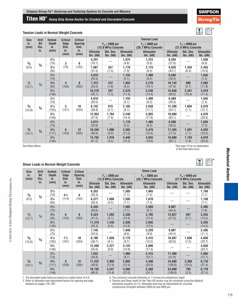
Sizein.
(mm)
DrillBitDia.in.
Embed.Depthin.
(mm)
CriticalEdgeDist.in.
(mm)
CriticalSpacingDist.in.
(mm)
TensionLoadf'c≥2000psi
(13.8MPa)Concretef'c≥3000psi
(20.7MPa)Concretef'c≥4000psi
(27.6MPa)ConcreteUltimatelbs.(kN)
Std.Dev.lbs.(kN)
Allowablelbs.(kN)
Allowablelbs.(kN)
Ultimatelbs.(kN)
Std.Dev.lbs.(kN)
Allowablelbs.(kN)
3⁄8 (9.5)
3⁄823⁄4 (70) 3
(76)6
(152)
4,297 (19.1) — 1,075
(4.8)1,315 (5.8)
6,204 (27.6) — 1,550
(6.9)33⁄4 (95)
7,087 (31.5)
347 (1.5)
1,770 (7.9)
2,115 (9.4)
9,820 (43.7)
1,434 (6.4)
2,455 (10.9)
1⁄2 (12.7)
1⁄2
23⁄4 (70)
4 (102)
8 (203)
4,610 (20.5) — 1,155
(5.1)1,400 (6.2)
6,580 (29.3) — 1,645
(7.3)35⁄8 (92)
7,413 (33.0)
412 (1.8)
1,855 (8.3)
2,270 (10.1)
10,742 (47.8)
600 (2.7)
2,685 (11.9)
53⁄4 (146)
10,278 (45.7)
297 (1.3)
2,570 (11.4)
3,240 (14.4)
15,640 (69.6)
2,341 (10.4)
3,910 (17.4)
5⁄8 (15.9)
5⁄8
23⁄4 (70)
5 (127)
10 (254)
4,610 (20.5) — 1,155
(5.1)1,400 (6.2)
6,580 (29.3) — 1,645
(7.3)41⁄8
(105)8,742 (38.9)
615 (2.7)
2,185 (9.7)
2,630 (11.7)
12,286 (54.7)
1,604 (7.1)
3,070 (13.7)
53⁄4 (146)
12,953 (57.6)
1,764 (7.8)
3,240 (14.4)
3,955 (17.6)
18,680 (83.1) — 4,670
(20.8)
3⁄4 (19.1)
3⁄4
23⁄4 (70)
6 (152)
12 (305)
4,674 (20.8) — 1,170
(5.2)1,405 (6.3)
6,580 (29.3) — 1,645
(7.3)45⁄8
(117)10,340 (46.0)
1,096 (4.9)
2,585 (11.5)
3,470 (15.4)
17,426 (77.5)
1,591 (7.1)
4,355 (19.4)
53⁄4 (146)
13,765 (61.2)
1,016 (4.5)
3,440 (15.3)
4,055 (18.0)
18,680 (83.1)
1,743 (7.8)
4,670 (20.8)
See Notes Below *See page 13 for an explanation of the load table icons
TensionLoadsinNormal-WeightConcrete
Sizein.
(mm)
DrillBitDia.in.
Embed.Depthin.
(mm)
CriticalEdgeDist.in.
(mm)
CriticalSpacingDist.in.
(mm)
ShearLoadf'c≥2000psi
(13.8MPa)Concretef'c≥3000psi
(20.7MPa)Concretef'c≥4000psi
(27.6MPa)ConcreteUltimatelbs.(kN)
Std.Dev.lbs.(kN)
Allowablelbs.(kN)
Allowablelbs.(kN)
Ultimatelbs.(kN)
Std.Dev.lbs.(kN)
Allowablelbs.(kN)
3⁄8 (9.5)
3⁄823⁄4 (70) 41⁄2
(114)6
(152)
6,353 (28.3) — 1,585
(7.1)1,665 (7.4) — — 1,740
(7.7)33⁄4 (95)
6,377 (28.4)
1,006 (4.5)
1,595 (7.1)
1,670 (7.4) — — 1,740
(7.7)
1⁄2 (12.7)
1⁄2
23⁄4 (70)
6 (152)
8 (203)
6,435 (28.6) — 1,605
(7.1)2,050 (9.1)
9,987 (44.4) — 2,495
(7.8)35⁄8 (92)
9,324 (41.5)
1,285 (5.7)
2,330 (10.4)
2,795 (12.4)
13,027 (57.9)
597 (2.7)
3,255 (14.5)
53⁄4 (146)
11,319 (50.3)
1,245 (5.5)
2,830 (12.6)
3,045 (13.5) — — 3,255
(14.5)
5⁄8 (15.9)
5⁄8
23⁄4 (70)
71⁄2 (191)
10 (254)
7,745 (34.5) — 1,940
(8.6)2,220 (9.9)
9,987 (44.4) — 2,495
(11.1)41⁄8
(105)8,706 (38.7)
1,830 (8.1)
2,175 (9.7)
3,415 (15.2)
18,607 (82.8)
1,650 (7.3)
4,650 (20.7)
53⁄4 (146)
12,498 (55.6)
2,227 (9.9)
3,125 (13.9)
3,890 (17.3) — — 4,650
(20.7)
3⁄4 (19.1)
3⁄4
23⁄4 (70)
9 (229)
12 (305)
7,832 (34.8) — 1,960
(8.7)2,415 (10.7)
11,460 (51.0) — 2,865
(12.7)45⁄8
(117)11,222 (49.9)
2,900 (12.9)
2,805 (12.5)
4,490 (20.0)
24,680 (109.8)
2,368 (10.5)
6,170 (27.4)
53⁄4 (146)
19,793 (88.0)
3,547 (15.8)
4,950 (22.0)
5,560 (24.7)
24,680 (109.8)
795 (3.5)
6,170 (27.4)
1. The allowable loads listed are based on a safety factor of 4.0.2. Refer to allowable load-adjustment factors for spacing and edge
distance on pages 119–120.
3. The minimum concrete thickness is 1 1⁄2 times the embedment depth.4.TensionandShearloadsfortheTitenHDanchormaybecombinedusingtheelliptical
interaction equation (n=5⁄3). Allowable load may be interpolated for concrete compressive strengths between 2000 psi and 4000 psi.
ShearLoadsinNormal-WeightConcrete
Simpson Strong-Tie ® Anchoring and Fastening Systems for Concrete and MasonryC-
SAS-
2012
©20
12 S
imps
on S
trong
-Tie
Com
pany
Inc.
115
Titen HD® Heavy Duty Screw Anchor for Cracked and Uncracked Concrete
Mec
hani
cal A
ncho
rs
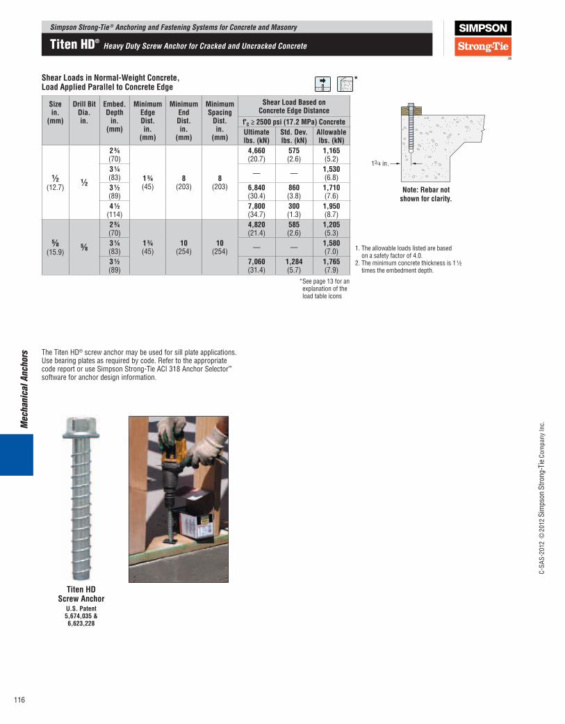
*
Sizein.
(mm)
DrillBitDia.in.
Embed.Depthin.
(mm)
MinimumEdgeDist.in.
(mm)
MinimumEndDist.in.
(mm)
MinimumSpacingDist.in.
(mm)
ShearLoadBasedonConcreteEdgeDistance
f'c≥2500psi(17.2MPa)ConcreteUltimatelbs.(kN)
Std.Dev.lbs.(kN)
Allowablelbs.(kN)
1⁄2 (12.7)
1⁄2
23⁄4 (70)
13⁄4 (45)
8 (203)
8 (203)
4,660 (20.7)
575 (2.6)
1,165 (5.2)
1. The allowable loads listed are based on a safety factor of 4.0.
2. The minimum concrete thickness is 1 1⁄2 times the embedment depth.
31⁄4 (83) — — 1,530
(6.8)31⁄2 (89)
6,840 (30.4)
860 (3.8)
1,710 (7.6)
41⁄2 (114)
7,800 (34.7)
300 (1.3)
1,950 (8.7)
5⁄8 (15.9)
5⁄8
23⁄4 (70)
13⁄4 (45)
10 (254)
10 (254)
4,820 (21.4)
585 (2.6)
1,205 (5.3)
31⁄4 (83) — — 1,580
(7.0)31⁄2 (89)
7,060 (31.4)
1,284 (5.7)
1,765 (7.9)
ShearLoadsinNormal-WeightConcrete,LoadAppliedParalleltoConcreteEdge
Note:Rebarnotshownforclarity.
*See page 13 for an explanation of the load table icons
TitenHDScrewAnchor
U.S.Patent5,674,035&6,623,228
TheTitenHD® screw anchor may be used for sill plate applications. Use bearing plates as required by code. Refer to the appropriate code report or use Simpson Strong-Tie ACI 318 Anchor Selector™ software for anchor design information.
Simpson Strong-Tie ® Anchoring and Fastening Systems for Concrete and Masonry
C-SA
S-20
12 ©
2012
Sim
pson
Stro
ng-T
ie C
ompa
ny In
c.
116
Titen HD® Heavy Duty Screw Anchor for Cracked and Uncracked Concrete
Mechanical Anchors
TensionLoadsinNormal-WeightConcrete,LoadAppliedat60°AngletoHorizontalforTilt-UpWallBraces
*
*
*
Sizein.
(mm)
DrillBitDia.in.
Embed.Depthin.
(mm)
StemwallWidthin.
(mm)
Min.EdgeDist.in.
(mm)
Min.EndDist.in.
(mm)
TensionLoadf'c≥2500psi(17.2MPa)Concrete
f'c≥4500psi(31.0MPa)Concrete
Ultimatelbs.(kN)
Allow.lbs.(kN)
Ultimatelbs.(kN)
Allow.lbs.(kN)
1⁄2 (12.7)
1⁄2 10 (254)
6 (152)
13⁄4 (44)
8 (203)
15,420 (68.6)
3,855 (17.1)
20,300 (90.3)
5,075 (22.6)
43⁄8 (111)
14,280 (63.5)
3,570 (15.9)
19,040 (84.7)
4,760 (21.2)
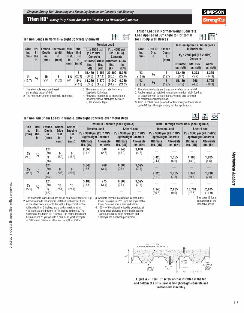
1. The allowable loads are based on a safety factor of 4.0.
2. The minimum anchor spacing is 15 inches.
3. The minimum concrete thickness (depth) is 12 inches.
4. Allowable loads may be interpolated for compressive strengths between 2,500 and 4,500 psi.
TensionLoadsinNormal-WeightConcreteStemwall
Sizein.
(mm)
DrillBitDia.in.
Embed.Depthin.
(mm)
TensionAppliedat60-degreestoHorizontal
f'c≥2500psi(17.2MPa)Concrete
Ultimatelbs.(kN)
Std.Dev.lbs.(kN)
Allow.lbs.(kN)
5⁄8 (15.9)
5⁄8 5 (127)
13,420 (59.7)
1,273 (5.7)
3,355 (14.9)
3⁄4 (19.1)
3⁄4 5 (127)
15,180 (67.5)
968 (4.3)
3,795 (16.9)
1. The allowable loads are based on a safety factor of 4.0.2. Anchor must be installed into a concrete floor slab, footing,
or deadman with sufficient area, weight, and strength to resist the anchorage load.
3.TitenHD® has been qualified for temporary outdoor use of up to 90 days through testing for this application.
Sizein.
(mm)
DrillBitDia.in.
Embed.Depthin.
(mm)
CriticalEdgeDist.in.
(mm)
CriticalSpacingDist.in.
(mm)
InstallinConcrete(seeFigureA) InstallthroughMetalDeck(seeFigureA)TensionLoad ShearLoad TensionLoad ShearLoad
f'c≥3000psi(20.7MPa)LightweightConcrete
f'c≥3000psi(20.7MPa)LightweightConcrete
f'c≥3000psi(20.7MPa)LightweightConcrete
f'c≥3000psi(20.7MPa)LightweightConcrete
Ultimatelbs.(kN)
Allowablelbs.(kN)
Ultimatelbs.(kN)
Allowablelbs.(kN)
Ultimatelbs.(kN)
Allowablelbs.(kN)
Ultimatelbs.(kN)
Allowablelbs.(kN)
3⁄8 (9.5)
3⁄823⁄4 (70) 6
(152)6
(152)
2,560 (11.4)
640 (2.8)
4,240 (18.9)
1,060 (4.7) — — — —
3 (76) — — — — 5,420
(24.1)1,355 (6.0)
4,100 (18.2)
1,025 (4.6)
1⁄2 (12.7)
1⁄223⁄4 (70) 8
(203)8
(203)
3,040 (13.5)
760 (3.4)
6,380 (28.4)
1,595 (7.1) — — — —
4 (102) — — — — 7,020
(31.2)1,755 (7.8)
6,840 (30.4)
1,710 (7.6)
5⁄8 (15.9)
5⁄823⁄4 (70) 10
(254)10
(254)
3,100 (13.8)
775 (3.4)
6,380 (28.4)
1,595 (7.1) — — — —
5 (127) — — — — 8,940
(39.8)2,235 (9.9)
10,700 (47.6)
2,675 (11.9)
1. The allowable loads listed are based on a safety factor of 4.0.2. Allowable loads for anchors installed in the lower flute
of the steel deck are for flutes with a trapezoidal profile with a depth of 3 inches, and a width varying from 4 1⁄2 inches at the bottom to 7 1⁄2 inches at the top. The spacing of the flutes is 12 inches. The metal deck must be minimum 20-gauge with a minimum yield strength of 38 ksi and minimum ultimate strength of 45 ksi.
3. Anchors may be installed off-center in the lower flute (up to 1 1⁄2" from the edge of the lower flute) without a load reduction.
4.100%oftheallowableloadispermittedat critical edge distance and critical spacing. Testing at smaller edge distances and spacings has not been performed.
TensionandShearLoadsinSand-LightweightConcreteoverMetalDeck
*See page 13 for an explanation of the load table icons
MIN. 3,000 PSI SAND-LIGHTWEIGHT CONCRETE
MIN.20 GAUGE
STEELDECKLOWER
FLUTE
UPPERFLUTE
3"
61⁄4"
11⁄2" 41⁄2"
41⁄2"71⁄2"
FigureA–TitenHD®screwanchorinstalledinthetopandbottomofastructuralsand-lightweight-concreteand
metal-deckassembly
Simpson Strong-Tie ® Anchoring and Fastening Systems for Concrete and MasonryC-
SAS-
2012
©20
12 S
imps
on S
trong
-Tie
Com
pany
Inc.
117
Titen HD® Heavy Duty Screw Anchor for Cracked and Uncracked Concrete
Mec
hani
cal A
ncho
rs
Sizein.
(mm)
DrillBitDia.in.
Min.Embed.Depthin.
(mm)
CriticalEdgeDist.in.
(mm)
CriticalEndDist.in.
(mm)
CriticalSpacingDist.in.
(mm)
Valuesfor8-inchLightweight,Medium-WeightorNormal-WeightGrout-FilledCMU
TensionLoad ShearLoadUltimatelbs.(kN)
Allowablelbs.(kN)
Ultimatelbs.(kN)
Allowablelbs.(kN)
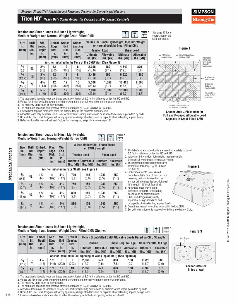
AnchorInstalledintheFaceoftheCMUWall(SeeFigure1)3⁄8
(9.5)3⁄8 23⁄4
(70)12
(305)12
(305)6
(152)2,390 (10.6)
480 (2.1)
4,340 (19.3)
870 (3.9)
1⁄2 (12.7)
1⁄2 31⁄2 (89)
12 (305)
12 (305)
8 (203)
3,440 (15.3)
690 (3.1)
6,920 (30.8)
1,385 (6.2)
5⁄8 (15.9)
5⁄8 41⁄2 (114)
12 (305)
12 (305)
10 (254)
5,300 (23.6)
1,060 (4.7)
10,420 (46.4)
2,085 (9.3)
3⁄4 (19.1)
3⁄4 51⁄2 (140)
12 (305)
12 (305)
12 (305)
7,990 (35.5)
1,600 (7.1)
15,000 (66.7)
3,000 (13.3)
1. The tabulated allowable loads are based on a safety factor of 5.0 for installations under the IBC and IRC. 2. Values for 8-inch wide, lightweight, medium-weight and normal-weight concrete masonry units.3. The masonry units must be fully grouted.4. The minimum specified compressive strength of masonry, f'm, at 28 days is 1,500 psi.5. Embedment depth is measured from the outside face of the concrete masonry unit.6. Allowable loads may be increased 33 1⁄3%forshort-termloadingduetowindorseismicforceswherepermittedbycode.7. Grout-filled CMU wall design must satisfy applicable design standards and be capable of withstanding applied loads.8. Refer to allowable load-adjustment factors for spacing and edge distance on page 121.
TensionandShearLoadsin8-inchLightweight,Medium-WeightandNormal-WeightGrout-FilledCMU
Sizein.
(mm)
DrillBitDia.in.
Embed.Depth4in.
(mm)
Min.EdgeDist.in.
(mm)
Min.EndDist.in.
(mm)
8-inchHollowCMULoadsBasedonCMUStrength
1. The tabulated allowable loads are based on a safety factor of 5.0 for installations under the IBC and IRC.
2. Values for 8-inch wide, lightweight, medium-weight and normal-weight concrete masonry units.
3. The minimum specified compressive strength of masonry, f'm, at 28 days is 1,500 psi.
4. Embedment depth is measured from the outside face of the concrete masonry unit and is based on the anchor being embedded an additional 1⁄2" through 1 1⁄4" thick face shell.
5. Allowable loads may not be increased for short-term loading due to wind or seismic forces. CMU wall design must satisfy applicable design standards and be capable of withstanding applied loads.
6.DonotuseimpactwrenchestoinstallinhollowCMU.7. Set drill to rotation-only mode when drilling into hollow CMU.
TensionLoad ShearLoad
Ultimatelbs.(kN)
Allowablelbs.(kN)
Ultimatelbs.(kN)
Allowablelbs.(kN)
AnchorInstalledinFaceShell(SeeFigure2)3⁄8
(9.5)3⁄8 13⁄4
(44)4
(102)45⁄8
(117)720 (3.2)
145 (0.6)
1,240 (5.5)
250 (1.1)
1⁄2 (12.7)
1⁄2 13⁄4 (44)
4 (102)
45⁄8 (117)
760 (3.4)
150 (0.7)
1,240 (5.5)
250 (1.1)
5⁄8 (15.9)
5⁄8 13⁄4 (44)
4 (102)
45⁄8 (117)
800 (3.6)
160 (0.7)
1,240 (5.5)
250 (1.1)
3⁄4 (19.1)
3⁄4 13⁄4 (44)
4 (102)
45⁄8 (117)
880 (3.9)
175 (0.8)
1,240 (5.5)
250 (1.1)
TensionandShearLoadsin8-inchLightweight,Medium-WeightandNormal-WeightHollowCMU
45⁄8"4"
Installations in this area forfull allowable load capacity
Installationin this areafor reducedallowableload capacity
4" Minimumend distance
Critical enddistance(see load table)
No installationwithin 1¼" ofhead joint
4" Minimumedge distance
Critical edge distance(see load table)
Figure1
Figure2
ShadedArea=PlacementforFullandReducedAllowableLoadCapacityinGrout-FilledCMU
*
*
Sizein.
(mm)
DrillBitDia.in.
Embed.Depthin.
(mm)
Min.EdgeDist.in.
(mm)
Min.EndDist.in.
(mm)
CriticalSpacingDist.in.
(mm)
8-inchGrout-FilledCMUAllowableLoadsBasedonCMUStrength
Tension ShearPerp.toEdge ShearParalleltoEdge
Ultimatelbs.(kN)
Allowablelbs.(kN)
Ultimatelbs.(kN)
Allowablelbs.(kN)
Ultimatelbs.(kN)
Allowablelbs.(kN)
AnchorInstalledinCellOpeningorWeb(TopofWall)(SeeFigure3)1⁄2
(12.7)1⁄2 41⁄2
(114)13⁄4
(44.5)8
(203)8
(203)2,860 (12.7)
570 (2.5)
800 (3.6)
160 (0.7)
2,920 (13.0)
585 (2.6)
5⁄8 (15.9)
5⁄8 41⁄2 (114)
13⁄4 (44.5)
10 (254)
10 (254)
2,860 (12.7)
570 (2.5)
800 (3.6)
160 (0.7)
3,380 (15.0)
675 (3.0)
TensionandShearLoadsin8-inchLightweight,Medium-WeightandNormal-WeightGrout-FilledCMUStemwall
Anchorinstalledintopofwall
13⁄4" Edge
Figure3*
1. The tabulated allowable loads are based on a safety factor of 5.0 for installations under the IBC and IRC. 2. Values are for 8-inch wide, lightweight, medium-weight and normal-weight concrete masonry units.3. The masonry units must be fully grouted.4. The minimum specified compressive strength of masonry, f'm, at 28 days is 1,500 psi.5. Allowable loads may be increased 33 1⁄3%forshort-termloadingduetowindorseismicforceswherepermittedbycode.6. Grout-filled CMU wall design must satisfy applicable design standards and be capable of withstanding applied design loads.7. Loads are based on anchor installed in either the web or grout-filled cell opening in the top of wall.
*See page 13 for an explanation of the load table icons
Simpson Strong-Tie ® Anchoring and Fastening Systems for Concrete and Masonry
C-SA
S-20
12 ©
2012
Sim
pson
Stro
ng-T
ie C
ompa
ny In
c.
118
Titen HD® Heavy Duty Screw Anchor for Cracked and Uncracked Concrete

Mechanical Anchors
Load-AdjustmentFactorsforTitenHD®AnchorsinNormal-WeightConcrete:EdgeDistance,TensionandShearLoads
1. The following tables are for reduced edge distance. 2. Locate the anchor size to be used for either a tension and/or shear load application. 3. Locate the anchor embedment (E) used for either a tension and/or shear load application.
Howtousethesecharts:
*
4. Locate the edge distance (Cact) at which the anchor is to be installed. 5. The load adjustment factor (fc) is the intersection of the row and column. 6. Multiply the allowable load by the applicable load adjustment factor(s). 7. Reduction factors for multiple edges are multiplied together.
EdgeDist.Cact(in.)
Dia. 3⁄8 1⁄2 5⁄8 3⁄4 *See page 13 for an explanation of the load table iconsE 23⁄4 33⁄4 23⁄4 35⁄8 53⁄4 23⁄4 41⁄8 53⁄4 23⁄4 45⁄8 53⁄4
Ccr 3 3 4 4 4 5 5 5 6 6 6Cmin 13⁄4 13⁄4 13⁄4 13⁄4 13⁄4 13⁄4 13⁄4 13⁄4 13⁄4 13⁄4 13⁄4fcmin 0.83 0.73 0.67 0.57 0.73 0.67 0.57 0.59 0.67 0.48 0.58
1 3⁄4 0.83 0.73 0.67 0.57 0.73 0.67 0.57 0.59 0.67 0.48 0.582 0.86 0.78 0.71 0.62 0.76 0.70 0.60 0.62 0.69 0.51 0.60
2 1⁄4 0.90 0.84 0.74 0.67 0.79 0.72 0.64 0.65 0.71 0.54 0.632 1⁄2 0.93 0.89 0.78 0.71 0.82 0.75 0.67 0.68 0.73 0.57 0.652 3⁄4 0.97 0.95 0.82 0.76 0.85 0.77 0.70 0.72 0.75 0.60 0.683 1.00 1.00 0.85 0.81 0.88 0.80 0.74 0.75 0.77 0.63 0.70
3 1⁄4 0.89 0.86 0.91 0.82 0.77 0.78 0.79 0.66 0.733 1⁄2 0.93 0.90 0.94 0.85 0.80 0.81 0.81 0.69 0.753 3⁄4 0.96 0.95 0.97 0.87 0.83 0.84 0.83 0.72 0.784 1.00 1.00 1.00 0.90 0.87 0.87 0.84 0.76 0.80
4 1⁄4 0.92 0.90 0.91 0.86 0.79 0.834 1⁄2 0.95 0.93 0.94 0.88 0.82 0.854 3⁄4 0.97 0.97 0.97 0.90 0.85 0.885 1.00 1.00 1.00 0.92 0.88 0.90
5 1⁄4 0.94 0.91 0.935 1⁄2 0.96 0.94 0.955 3⁄4 0.98 0.97 0.986 1.00 1.00 1.00
See Notes Below
EdgeDistanceTension(fc)
EdgeDist.Cact(in.)
Dia. 3⁄8 1⁄2 5⁄8 3⁄4
The tabled adjustment values (fc) have been calculated using the following information:1. E = Embedment depth (inches).2. Cact = actual edge distance at
which anchor is installed (inches).3. Ccr = critical edge distance for 100%load(inches).
4. Cmin = minimum edge distance for reduced load (inches).
5. fc = percent of allowable load at actual edge distance.
6. fccr = percentage of allowable load at critical edge distance. fccr is always = 1.00.
7. fcmin = percent of allowable load at minimum edge distance.
8. fc = fcmin + [(1 - fcmin) (Cact - Cmin) / (Ccr - Cmin)].
E 23⁄4 33⁄4 23⁄4 35⁄8 53⁄4 23⁄4 41⁄8 53⁄4 23⁄4 45⁄8 53⁄4Ccr 41⁄2 41⁄2 6 6 6 71⁄2 71⁄2 71⁄2 9 9 9Cmin 13⁄4 13⁄4 13⁄4 13⁄4 13⁄4 13⁄4 13⁄4 13⁄4 13⁄4 13⁄4 13⁄4fcmin 0.25 0.24 0.25 0.20 0.17 0.19 0.16 0.19 0.19 0.14 0.13
1 3⁄4 0.25 0.24 0.25 0.20 0.17 0.19 0.16 0.19 0.19 0.14 0.132 0.32 0.31 0.29 0.25 0.22 0.23 0.20 0.23 0.22 0.17 0.16
2 1⁄2 0.45 0.45 0.38 0.34 0.32 0.30 0.27 0.30 0.27 0.23 0.223 0.59 0.59 0.47 0.44 0.41 0.37 0.34 0.37 0.33 0.29 0.28
3 1⁄2 0.73 0.72 0.56 0.53 0.51 0.44 0.42 0.44 0.39 0.35 0.344 0.86 0.86 0.65 0.62 0.61 0.51 0.49 0.51 0.44 0.41 0.40
4 1⁄2 1.00 1.00 0.74 0.72 0.71 0.58 0.56 0.58 0.50 0.47 0.465 0.82 0.81 0.80 0.65 0.63 0.65 0.55 0.53 0.52
5 1⁄2 0.91 0.91 0.90 0.72 0.71 0.72 0.61 0.58 0.586 1.00 1.00 1.00 0.79 0.78 0.79 0.66 0.64 0.64
6 1⁄2 0.86 0.85 0.86 0.72 0.70 0.707 0.93 0.93 0.93 0.78 0.76 0.76
7 1⁄2 1.00 1.00 1.00 0.83 0.82 0.828 0.89 0.88 0.88
8 1⁄2 0.94 0.94 0.949 1.00 1.00 1.00
EdgeDistanceShear(fc)*
ThesetablesarenotforusewithSDdesignmethods
Simpson Strong-Tie ® Anchoring and Fastening Systems for Concrete and MasonryC-
SAS-
2012
©20
12 S
imps
on S
trong
-Tie
Com
pany
Inc.
119
Titen HD® Technical Information

Mec
hani
cal A
ncho
rs
Load-AdjustmentFactorsforTitenHD®AnchorsinNormal-WeightConcrete:Spacing,TensionandShearLoads
1. The following tables are for reduced spacing. 2. Locate the anchor size to be used for either a tension and/or shear load application. 3. Locate the anchor embedment (E) used for either a tension and/or shear load application.
Howtousethesecharts:4. Locate the spacing (Sact) at which the anchor is to be installed. 5. The load adjustment factor (fs) is the intersection of the row and column. 6. Multiply the allowable load by the applicable load adjustment factor(s). 7. Reduction factors for multiple spacings are multiplied together.
*
Sact(in.)
Dia. 3⁄8 1⁄2 5⁄8 3⁄4 *See page 13 for an explanation of the load table iconsE 23⁄4 33⁄4 23⁄4 35⁄8 53⁄4 23⁄4 41⁄8 53⁄4 23⁄4 45⁄8 53⁄4
Scr 6 6 8 8 8 10 10 10 12 12 12Smin 11⁄2 11⁄2 2 2 2 21⁄2 21⁄2 21⁄2 3 3 3fsmin 0.66 0.56 0.72 0.63 0.76 0.79 0.69 0.73 0.80 0.70 0.72
1 1⁄2 0.66 0.562 0.70 0.61 0.72 0.63 0.76
2 1⁄2 0.74 0.66 0.74 0.66 0.78 0.79 0.69 0.733 0.77 0.71 0.77 0.69 0.80 0.80 0.71 0.75 0.80 0.70 0.724 0.85 0.80 0.81 0.75 0.84 0.83 0.75 0.78 0.82 0.73 0.755 0.92 0.90 0.86 0.82 0.88 0.86 0.79 0.82 0.84 0.77 0.786 1.00 1.00 0.91 0.88 0.92 0.89 0.83 0.86 0.87 0.80 0.817 0.95 0.94 0.96 0.92 0.88 0.89 0.89 0.83 0.848 1.00 1.00 1.00 0.94 0.92 0.93 0.91 0.87 0.889 0.97 0.96 0.96 0.93 0.90 0.9110 1.00 1.00 1.00 0.96 0.93 0.9411 0.98 0.97 0.9712 1.00 1.00 1.00
See Notes Below
SpacingTension(fs)
Sact(in.)
Dia. 3⁄8 1⁄2 5⁄8 3⁄4
The tabled adjustment values (fs) have been calculated using the following information:1. E = Embedment depth (inches).2. Sact = actual spacing distance at
which anchors are installed (inches).
3. Scr = critical spacing distance for 100%load(inches).
4. Smin = minimum spacing distance for reduced load (inches).
5. fs = adjustment factor for allowable load at actual spacing distance.
6. fscr = adjustment factor for allowable load at critical spacing distance. fscr is always = 1.00.
7. fsmin = adjustment factor for allowable load at minimum spacing distance.
8. fs = fsmin + [(1 - fsmin) (Sact - Smin) / (Scr - Smin)].
E 23⁄4 33⁄4 23⁄4 35⁄8 53⁄4 23⁄4 41⁄8 53⁄4 23⁄4 45⁄8 53⁄4Scr 6 6 8 8 8 10 10 10 12 12 12Smin 11⁄2 11⁄2 2 2 2 21⁄2 21⁄2 21⁄2 3 3 3fsmin 0.77 0.77 0.77 0.77 0.77 0.77 0.77 0.77 0.77 0.77 0.77
1 1⁄2 0.77 0.772 0.80 0.80 0.77 0.77 0.77
2 1⁄2 0.82 0.82 0.79 0.79 0.79 0.77 0.77 0.773 0.85 0.85 0.81 0.81 0.81 0.79 0.79 0.79 0.77 0.77 0.774 0.90 0.90 0.85 0.85 0.85 0.82 0.82 0.82 0.80 0.80 0.805 0.95 0.95 0.89 0.89 0.89 0.85 0.85 0.85 0.82 0.82 0.826 1.00 1.00 0.92 0.92 0.92 0.88 0.88 0.88 0.85 0.85 0.857 0.96 0.96 0.96 0.91 0.91 0.91 0.87 0.87 0.878 1.00 1.00 1.00 0.94 0.94 0.94 0.90 0.90 0.909 0.97 0.97 0.97 0.92 0.92 0.9210 1.00 1.00 1.00 0.95 0.95 0.9511 0.97 0.97 0.9712 1.00 1.00 1.00
SpacingShear(fs)*
ThesetablesarenotforusewithSDdesignmethods
Simpson Strong-Tie ® Anchoring and Fastening Systems for Concrete and Masonry
C-SA
S-20
12 ©
2012
Sim
pson
Stro
ng-T
ie C
ompa
ny In
c.
120
Titen HD® Technical Information
Mechanical Anchors
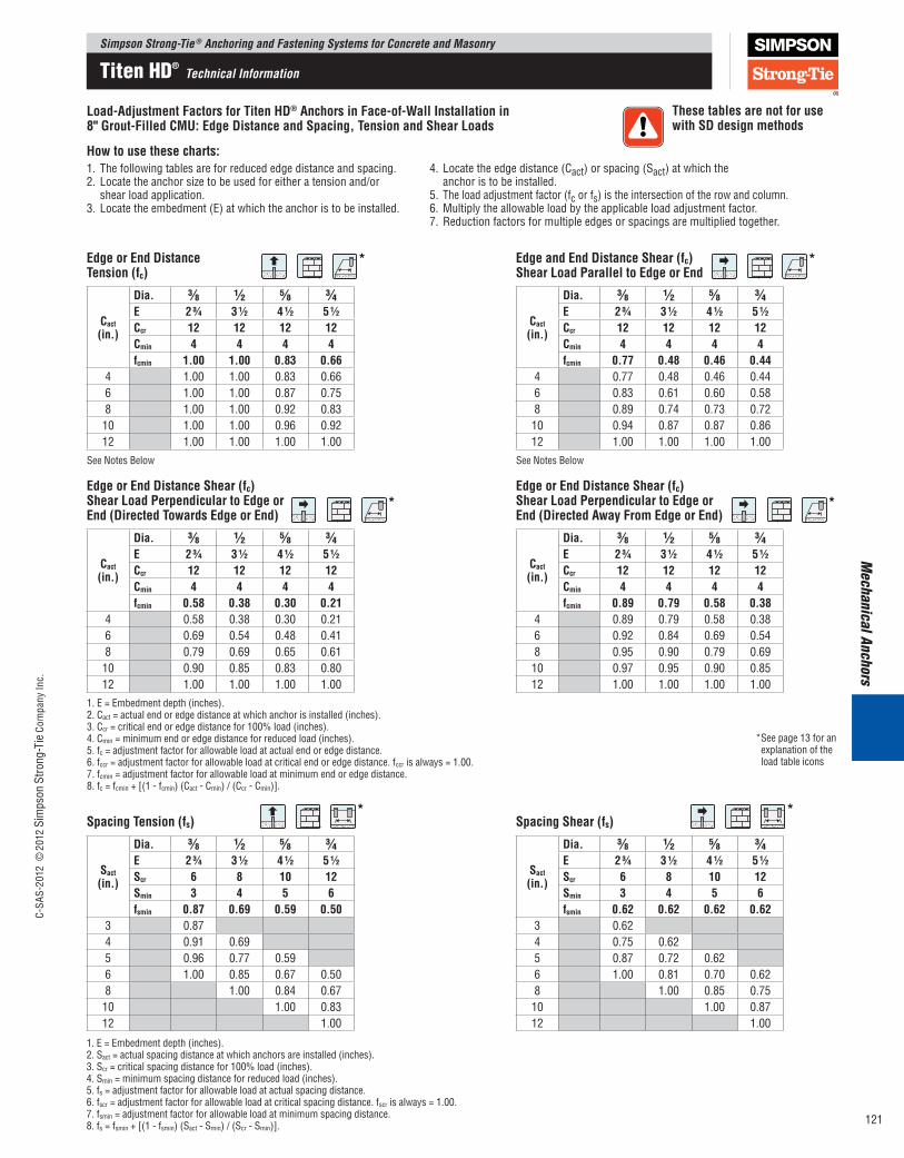
Load-AdjustmentFactorsforTitenHD®AnchorsinFace-of-WallInstallationin8"Grout-FilledCMU:EdgeDistanceandSpacing,TensionandShearLoads
Howtousethesecharts:1. The following tables are for reduced edge distance and spacing. 2. Locate the anchor size to be used for either a tension and/or shear load application. 3. Locate the embedment (E) at which the anchor is to be installed.
4. Locate the edge distance (Cact) or spacing (Sact) at which the anchor is to be installed. 5. The load adjustment factor (fc or fs) is the intersection of the row and column. 6. Multiply the allowable load by the applicable load adjustment factor. 7. Reduction factors for multiple edges or spacings are multiplied together.
Cact(in.)
Dia. 3⁄8 1⁄2 5⁄8 3⁄4E 23⁄4 31⁄2 41⁄2 51⁄2Ccr 12 12 12 12Cmin 4 4 4 4fcmin 1.00 1.00 0.83 0.66
4 1.00 1.00 0.83 0.666 1.00 1.00 0.87 0.758 1.00 1.00 0.92 0.8310 1.00 1.00 0.96 0.9212 1.00 1.00 1.00 1.00
See Notes Below
EdgeorEndDistanceTension(fc)
Cact(in.)
Dia. 3⁄8 1⁄2 5⁄8 3⁄4E 23⁄4 31⁄2 41⁄2 51⁄2Ccr 12 12 12 12Cmin 4 4 4 4fcmin 0.77 0.48 0.46 0.44
4 0.77 0.48 0.46 0.446 0.83 0.61 0.60 0.588 0.89 0.74 0.73 0.7210 0.94 0.87 0.87 0.8612 1.00 1.00 1.00 1.00
See Notes Below
EdgeandEndDistanceShear(fc)ShearLoadParalleltoEdgeorEnd
Cact(in.)
Dia. 3⁄8 1⁄2 5⁄8 3⁄4E 23⁄4 31⁄2 41⁄2 51⁄2Ccr 12 12 12 12Cmin 4 4 4 4fcmin 0.58 0.38 0.30 0.21
4 0.58 0.38 0.30 0.216 0.69 0.54 0.48 0.418 0.79 0.69 0.65 0.6110 0.90 0.85 0.83 0.8012 1.00 1.00 1.00 1.00
1. E = Embedment depth (inches).2. Cact = actual end or edge distance at which anchor is installed (inches).3. Ccr=criticalendoredgedistancefor100%load(inches).4. Cmin = minimum end or edge distance for reduced load (inches).5. fc = adjustment factor for allowable load at actual end or edge distance.6. fccr = adjustment factor for allowable load at critical end or edge distance. fccr is always = 1.00.7. fcmin = adjustment factor for allowable load at minimum end or edge distance.8. fc = fcmin + [(1 - fcmin) (Cact - Cmin) / (Ccr - Cmin)].
EdgeorEndDistanceShear(fc)ShearLoadPerpendiculartoEdgeorEnd(DirectedTowardsEdgeorEnd)
Cact(in.)
Dia. 3⁄8 1⁄2 5⁄8 3⁄4E 23⁄4 31⁄2 41⁄2 51⁄2Ccr 12 12 12 12Cmin 4 4 4 4fcmin 0.89 0.79 0.58 0.38
4 0.89 0.79 0.58 0.386 0.92 0.84 0.69 0.548 0.95 0.90 0.79 0.6910 0.97 0.95 0.90 0.8512 1.00 1.00 1.00 1.00
EdgeorEndDistanceShear(fc)ShearLoadPerpendiculartoEdgeorEnd(DirectedAwayFromEdgeorEnd)
Sact(in.)
Dia. 3⁄8 1⁄2 5⁄8 3⁄4E 23⁄4 31⁄2 41⁄2 51⁄2Scr 6 8 10 12Smin 3 4 5 6fsmin 0.87 0.69 0.59 0.50
3 0.874 0.91 0.695 0.96 0.77 0.596 1.00 0.85 0.67 0.508 1.00 0.84 0.6710 1.00 0.8312 1.00
SpacingTension(fs)
Sact(in.)
Dia. 3⁄8 1⁄2 5⁄8 3⁄4E 23⁄4 31⁄2 41⁄2 51⁄2Scr 6 8 10 12Smin 3 4 5 6fsmin 0.62 0.62 0.62 0.62
3 0.624 0.75 0.625 0.87 0.72 0.626 1.00 0.81 0.70 0.628 1.00 0.85 0.7510 1.00 0.8712 1.00
SpacingShear(fs)
ThesetablesarenotforusewithSDdesignmethods
*
*
*
*
*
*
1. E = Embedment depth (inches).2. Sact = actual spacing distance at which anchors are installed (inches).3. Scr=criticalspacingdistancefor100%load(inches).4. Smin = minimum spacing distance for reduced load (inches).5. fs = adjustment factor for allowable load at actual spacing distance.6. fscr = adjustment factor for allowable load at critical spacing distance. fscr is always = 1.00.7. fsmin = adjustment factor for allowable load at minimum spacing distance.8. fs = fsmin + [(1 - fsmin) (Sact - Smin) / (Scr - Smin)].
*See page 13 for an explanation of the load table icons
Simpson Strong-Tie ® Anchoring and Fastening Systems for Concrete and MasonryC-
SAS-
2012
©20
12 S
imps
on S
trong
-Tie
Com
pany
Inc.
121
Titen HD® Technical Information
Mec
hani
cal A
ncho
rsSimpson Strong-Tie ® Anchoring and Fastening Systems for Concrete and Masonry
C-SA
S-20
12 ©
2012
Sim
pson
Stro
ng-T
ie C
ompa
ny In
c.
122
*
*
*See page 13 for an explanation of the load table icons
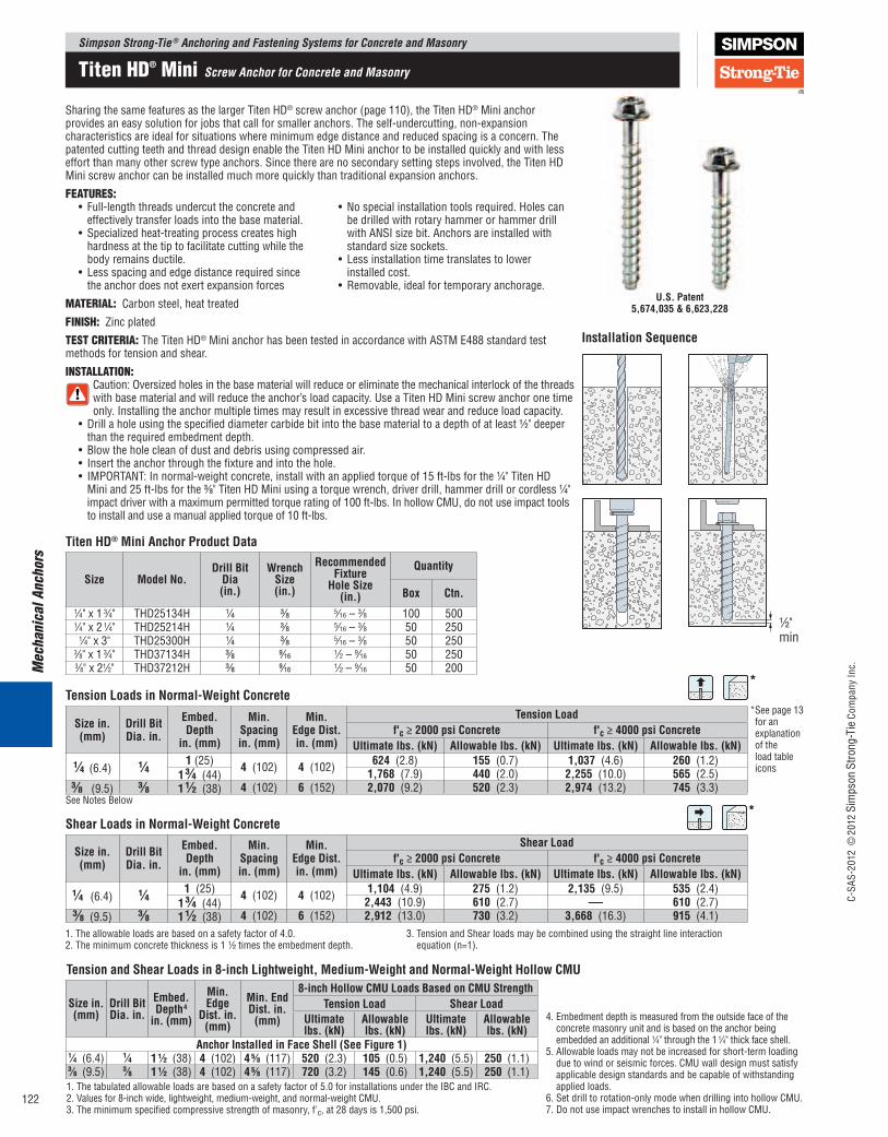
TensionLoadsinNormal-WeightConcrete
Sizein.(mm)
DrillBitDia.in.
Embed.Depth
in.(mm)
Min.Spacingin.(mm)
Min.EdgeDist.in.(mm)
TensionLoadf'c≥2000psiConcrete f'c≥4000psiConcrete
Ultimatelbs.(kN) Allowablelbs.(kN) Ultimatelbs.(kN) Allowablelbs.(kN)1⁄4 (6.4) 1⁄4
1(25) 4 (102) 4 (102) 624 (2.8) 155 (0.7) 1,037 (4.6) 260 (1.2)13⁄4 (44) 1,768 (7.9) 440 (2.0) 2,255 (10.0) 565 (2.5)
3⁄8 (9.5) 3⁄8 11⁄2 (38) 4 (102) 6 (152) 2,070 (9.2) 520 (2.3) 2,974 (13.2) 745 (3.3)See Notes Below
ShearLoadsinNormal-WeightConcrete
Sizein.(mm)
DrillBitDia.in.
Embed.Depth
in.(mm)
Min.Spacingin.(mm)
Min.EdgeDist.in.(mm)
ShearLoadf'c≥2000psiConcrete f'c≥4000psiConcrete
Ultimatelbs.(kN) Allowablelbs.(kN) Ultimatelbs.(kN) Allowablelbs.(kN)1⁄4(6.4) 1⁄4 1(25) 4(102) 4(102) 1,104(4.9) 275(1.2) 2,135(9.5) 535(2.4)
13⁄4(44) 2,443(10.9) 610(2.7) — 610(2.7)3⁄8(9.5) 3⁄8 11⁄2(38) 4(102) 6(152) 2,912(13.0) 730(3.2) 3,668(16.3) 915(4.1)
SharingthesamefeaturesasthelargerTitenHD®screwanchor(page110),theTitenHD® Mini anchor provides an easy solution for jobs that call for smaller anchors. The self-undercutting, non-expansion characteristics are ideal for situations where minimum edge distance and reduced spacing is a concern. The patentedcuttingteethandthreaddesignenabletheTitenHDMinianchortobeinstalledquicklyandwithlesseffortthanmanyotherscrewtypeanchors.Sincetherearenosecondarysettingstepsinvolved,theTitenHDMini screw anchor can be installed much more quickly than traditional expansion anchors.
FEATURES: • Full-lengththreadsundercuttheconcreteand
effectively transfer loads into the base material.• Specializedheat-treatingprocesscreateshigh
hardness at the tip to facilitate cutting while the body remains ductile.
• Lessspacingandedgedistancerequiredsincethe anchor does not exert expansion forces
• Nospecialinstallationtoolsrequired.Holescanbe drilled with rotary hammer or hammer drill with ANSI size bit. Anchors are installed with standard size sockets.
• Lessinstallationtimetranslatestolower installed cost.
• Removable,idealfortemporaryanchorage.
MATERiAl: Carbon steel, heat treated
FiNiSH: Zinc plated
TEST CRiTERiA: TheTitenHD® Mini anchor has been tested in accordance with ASTM E488 standard test methods for tension and shear.
iNSTAllATiON: Caution: Oversized holes in the base material will reduce or eliminate the mechanical interlock of the threads withbasematerialandwillreducetheanchor’sloadcapacity.UseaTitenHDMiniscrewanchoronetimeonly. Installing the anchor multiple times may result in excessive thread wear and reduce load capacity.
• Drillaholeusingthespecifieddiametercarbidebitintothebasematerialtoadepthofatleast1⁄2" deeper than the required embedment depth.
• Blowtheholecleanofdustanddebrisusingcompressedair.• Inserttheanchorthroughthefixtureandintothehole.• IMPORTANT:Innormal-weightconcrete,installwithanappliedtorqueof15ft-lbsforthe1⁄4"TitenHD
Mini and 25 ft-lbs for the 3⁄8"TitenHDMiniusingatorquewrench,driverdrill,hammerdrillorcordless1⁄4" impact driver with a maximum permitted torque rating of 100 ft-lbs. In hollow CMU, do not use impact tools to install and use a manual applied torque of 10 ft-lbs.
TitenHD®MiniAnchorProductData
Size ModelNo.DrillBitDia(in.)
WrenchSize(in.)
RecommendedFixture
HoleSize(in.)
Quantity
Box Ctn.1⁄4" x 1 3⁄4" THD25134H 1⁄4 3⁄8 5⁄16 – 3⁄8 100 5001⁄4" x 2 1⁄4" THD25214H 1⁄4 3⁄8 5⁄16 – 3⁄8 50 250
1⁄4" x 3" THD25300H 1⁄4 3⁄8 5⁄16 – 3⁄8 50 2503⁄8" x 1 3⁄4" THD37134H 3⁄8 9⁄16 1⁄2 – 9⁄16 50 2503⁄8" x 21⁄2" THD37212H 3⁄8 9⁄16 1⁄2 – 9⁄16 50 200
1. The allowable loads are based on a safety factor of 4.0.2. The minimum concrete thickness is 1 1⁄2 times the embedment depth.
3. Tension and Shear loads may be combined using the straight line interaction equation (n=1).
U.S.Patent5,674,035&6,623,228
InstallationSequence
1⁄2" min.1⁄2"min
Titen HD® Mini Screw Anchor for Concrete and Masonry
Sizein.(mm)
DrillBitDia.in.
Embed.Depth4in.(mm)
Min.Edge
Dist.in.(mm)
Min.EndDist.in.(mm)
8-inchHollowCMULoadsBasedonCMUStrengthTensionLoad ShearLoad
Ultimatelbs.(kN)
Allowablelbs.(kN)
Ultimatelbs.(kN)
Allowablelbs.(kN)
AnchorInstalledinFaceShell(SeeFigure1)1⁄4 (6.4) 1⁄4 11⁄2 (38) 4 (102) 45⁄8 (117) 520 (2.3) 105 (0.5) 1,240 (5.5) 250 (1.1)3⁄8 (9.5) 3⁄8 11⁄2 (38) 4 (102) 45⁄8 (117) 720 (3.2) 145 (0.6) 1,240 (5.5) 250 (1.1)
TensionandShearLoadsin8-inchLightweight,Medium-WeightandNormal-WeightHollowCMU
1. The tabulated allowable loads are based on a safety factor of 5.0 for installations under the IBC and IRC. 2. Values for 8-inch wide, lightweight, medium-weight, and normal-weight CMU.3. The minimum specified compressive strength of masonry, f'c, at 28 days is 1,500 psi.
4. Embedment depth is measured from the outside face of the concrete masonry unit and is based on the anchor being embedded an additional 1⁄4" through the 1 1⁄4" thick face shell.
5. Allowable loads may not be increased for short-term loading due to wind or seismic forces. CMU wall design must satisfy applicable design standards and be capable of withstanding applied loads.
6. Set drill to rotation-only mode when drilling into hollow CMU.7. DonotuseimpactwrenchestoinstallinhollowCMU.

TheTitenHD® rod hanger is a high-strength screw anchor designed to suspend threaded rod from concrete slabs and beams in order to hang pipes, cable tray and HVAC equipment. This anchor is code listed by ICC-ES for cracked and uncracked concrete applications under the 2009 IBC.
FEATURES:• High-load capacity as a result of the full-length threads that undercut the
concrete and effectively transfer load into the base material• Specialized heat-treating process creates greater hardness at the tip to
facilitate cutting while the body remains ductile• Serrated cutting teeth and patented thread design enable quick and easy
installation• No special installation tools required. Holes can be drilled with a rotary
hammer or hammer drill with standard ANSI-size bit. Anchors are installed with standard-size sockets.
MATERiAl: Carbon steel, heat treated
FiNiSH: Zinc plated
iNSTAllATiON: Caution: Oversized holes in the base material will reduce or eliminate the mechanical interlock of the threads with base material
andwillreducetheanchor’sloadcapacity.UseaTitenHD® Rod Hanger one time only. Installing the anchor multiple times may result in excessive thread wear and reduce load capacity• Drillaholeusingthespecifieddiametercarbidebitintothebase
material to a depth of at least 1⁄2" deeper than the required embedment. • Blow the hole clean of dust and debris using compressed air.• IMPORTANT: Install with an applied torque of 15 ft-lbs for the
THD25112RHandTHD37218RHrodhangersusingatorquewrench,driver drill, hammer drill or cordless 1⁄4" impact driver with a maximum permitted torque rating of 100 ft-lb.
CODES: ICC-ES ESR-2713 (THD37212RH and THD50234RH), Factory Mutual 3031136 (THD50234RH and THD37218RH) and 3035761 (THD37212RH)
Size(in.) ModelNo.
AcceptsRodDia.(in.)
DrillBitDia.(in.)
WrenchSize(in.)
Min.Embed.(in.)
Quantity
Box Carton
1 ⁄4 x 1 1⁄2 THD25112RH 1 ⁄4 1⁄4 3⁄8 1 1⁄2 100 500
3⁄8 x 2 1⁄8 THD37218RH 3⁄8 1⁄4 1⁄2 2 1⁄8 50 250
3⁄8 x 2 1⁄2 THD37212RH 3⁄8 3⁄8 1⁄2 2 1⁄2 50 200
1⁄2 x 2 3⁄4 THD50234RH 1⁄2 3⁄8 11 ⁄16 2 3⁄4 50 100
TitenHD®RodHangerProductData
U.S. Patent5,674,035 & 6,623,228
1.Drillaholeusingthespecified diameter carbide bit into the base material to a depth of at least 1⁄2" deeper than the required embedment.
2. Blow the hole clean of dust and debris using compressed air.
InstallationSequence
½" min.
4. Install threaded rod in the anchor to support pipes, wiring, etc.
½" min.
3. Insert anchor into the hole. Tighten the anchor with an impact wrench or a torque wrench into the base material until the hex washer head contacts the base material.
½" min.
Mechanical Anchors
THD25112RHTHD37218RHTHD37212RH(3⁄8" dia. shank)
THD50234RH(3⁄8" dia. shank)
Simpson Strong-Tie ® Anchoring and Fastening Systems for Concrete and MasonryC-
SAS-
2012
©20
12 S
imps
on S
trong
-Tie
Com
pany
Inc.
123
Cracked &Uncracked CONCRETE
IBC®
2009
ESR-2713ICC-ESTiten HD®
Threaded Rod Hanger for Cracked and Uncracked Concrete
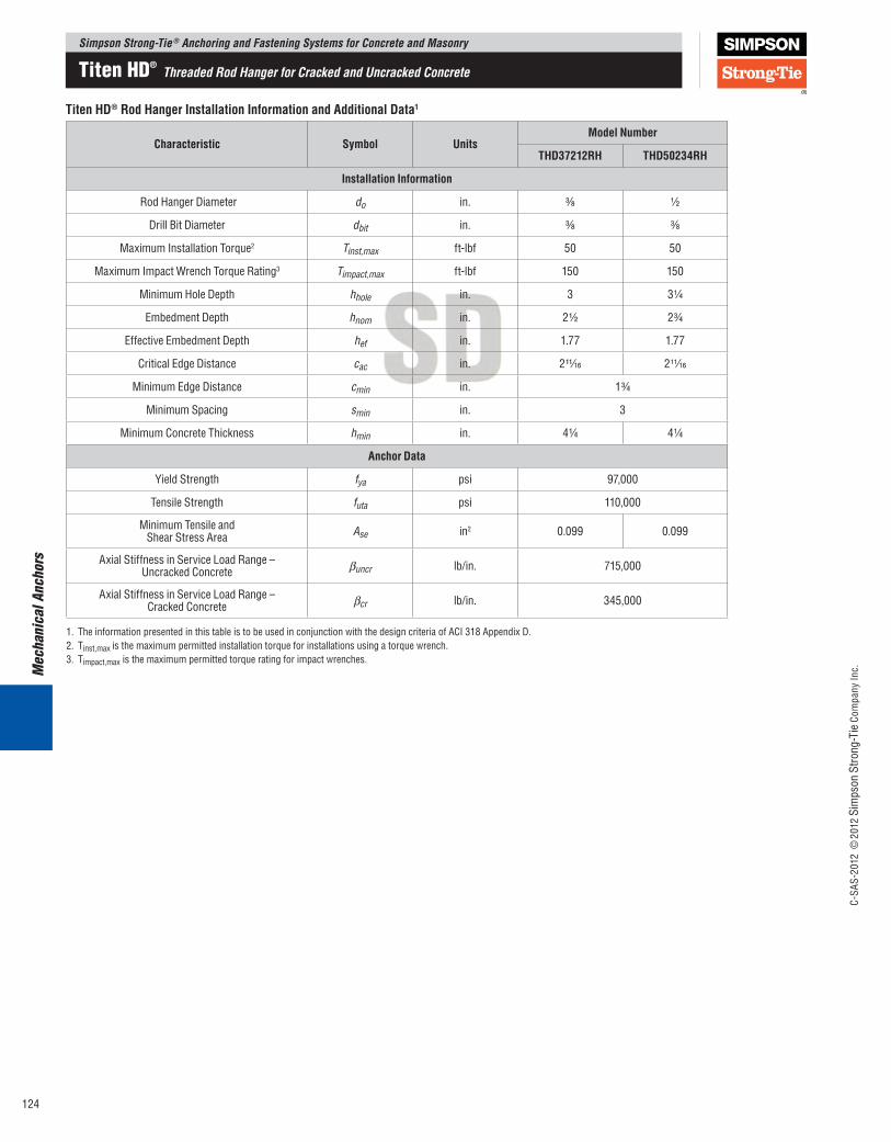
TitenHD®RodHangerInstallationInformationandAdditionalData1
Characteristic Symbol UnitsModelNumber
THD37212RH THD50234RH
InstallationInformation
RodHangerDiameter do in. 3⁄8 1⁄2
DrillBitDiameter dbit in. 3⁄8 3⁄8
Maximum Installation Torque2 Tinst,max ft-lbf 50 50
Maximum Impact Wrench Torque Rating3 Timpact,max ft-lbf 150 150
MinimumHoleDepth hhole in. 3 3 1⁄4
EmbedmentDepth hnom in. 2 1⁄2 2 3⁄4
EffectiveEmbedmentDepth hef in. 1.77 1.77
CriticalEdgeDistance cac in. 2 11⁄16 2 11⁄16
MinimumEdgeDistance cmin in. 1 3⁄4
Minimum Spacing smin in. 3
Minimum Concrete Thickness hmin in. 4 1⁄4 4 1⁄4
AnchorData
Yield Strength fya psi 97,000
Tensile Strength futa psi 110,000
Minimum Tensile andShear Stress Area Ase in2 0.099 0.099
Axial Stiffness in Service Load Range –Uncracked Concrete βuncr lb/in. 715,000
Axial Stiffness in Service Load Range –Cracked Concrete βcr lb/in. 345,000
1. TheinformationpresentedinthistableistobeusedinconjunctionwiththedesigncriteriaofACI318AppendixD.2. Tinst,max is the maximum permitted installation torque for installations using a torque wrench.3. Timpact,max is the maximum permitted torque rating for impact wrenches.
Mec
hani
cal A
ncho
rsSimpson Strong-Tie ® Anchoring and Fastening Systems for Concrete and Masonry
C-SA
S-20
12 ©
2012
Sim
pson
Stro
ng-T
ie C
ompa
ny In
c.
124
Titen HD® Threaded Rod Hanger for Cracked and Uncracked Concrete
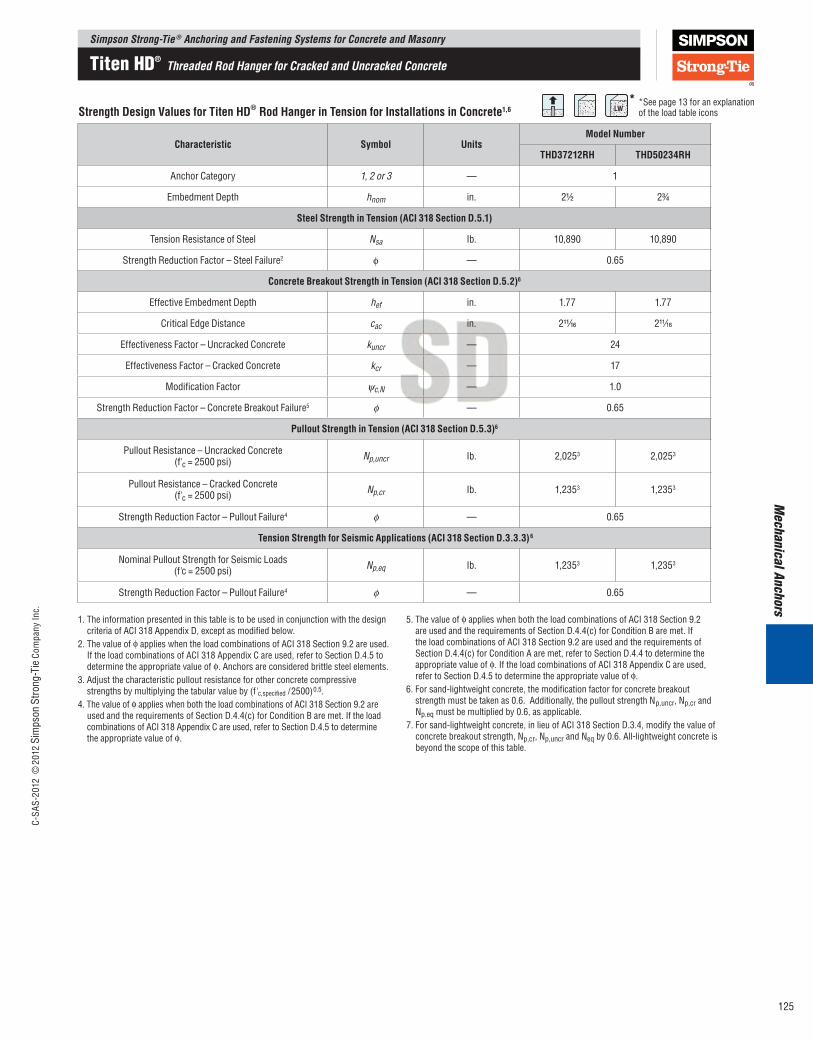
StrengthDesignValuesforTitenHD®RodHangerinTensionforInstallationsinConcrete1,6
Characteristic Symbol UnitsModelNumber
THD37212RH THD50234RH
Anchor Category 1, 2 or 3 — 1
EmbedmentDepth hnom in. 2 1⁄2 2 3⁄4
SteelStrengthinTension(ACI318SectionD.5.1)
Tension Resistance of Steel Nsa Ib. 10,890 10,890
Strength Reduction Factor – Steel Failure2 ϕ — 0.65
ConcreteBreakoutStrengthinTension(ACI318SectionD.5.2)6
EffectiveEmbedmentDepth hef in. 1.77 1.77
CriticalEdgeDistance cac in. 2 11⁄16 2 11⁄16
Effectiveness Factor – Uncracked Concrete kuncr — 24
Effectiveness Factor – Cracked Concrete kcr — 17
Modification Factor ψc,N — 1.0
Strength Reduction Factor – Concrete Breakout Failure5 ϕ — 0.65
PulloutStrengthinTension(ACI318SectionD.5.3)6
Pullout Resistance – Uncracked Concrete(f'c = 2500 psi) Np,uncr Ib. 2,0253 2,0253
Pullout Resistance – Cracked Concrete(f'c = 2500 psi) Np,cr Ib. 1,2353 1,2353
Strength Reduction Factor – Pullout Failure4 ϕ — 0.65
TensionStrengthforSeismicApplications(ACI318SectionD.3.3.3)6
Nominal Pullout Strength for Seismic Loads(f'c = 2500 psi) Np,eq Ib. 1,2353 1,2353
Strength Reduction Factor – Pullout Failure4 ϕ — 0.65
1. The information presented in this table is to be used in conjunction with the design criteriaofACI318AppendixD,exceptasmodifiedbelow.
2. The value of ϕ applies when the load combinations of ACI 318 Section 9.2 are used. IftheloadcombinationsofACI318AppendixCareused,refertoSectionD.4.5todetermine the appropriate value of ϕ. Anchors are considered brittle steel elements.
3. Adjust the characteristic pullout resistance for other concrete compressive strengths by multiplying the tabular value by (f'c,specified / 2500)0.5.
4. The value of ϕ applies when both the load combinations of ACI 318 Section 9.2 are usedandtherequirementsofSectionD.4.4(c)forConditionBaremet.IftheloadcombinationsofACI318AppendixCareused,refertoSectionD.4.5todeterminethe appropriate value of ϕ.
5. The value of ϕ applies when both the load combinations of ACI 318 Section 9.2 areusedandtherequirementsofSectionD.4.4(c)forConditionBaremet.Ifthe load combinations of ACI 318 Section 9.2 are used and the requirements of SectionD.4.4(c)forConditionAaremet,refertoSectionD.4.4todeterminetheappropriate value of ϕ. If the load combinations of ACI 318 Appendix C are used, refertoSectionD.4.5todeterminetheappropriatevalueofϕ.
6. For sand-lightweight concrete, the modification factor for concrete breakout strength must be taken as 0.6. Additionally, the pullout strength Np,uncr, Np,cr and Np.eq must be multiplied by 0.6, as applicable.
7.Forsand-lightweightconcrete,inlieuofACI318SectionD.3.4,modifythevalueofconcrete breakout strength, Np,cr, Np,uncr and Neq by 0.6. All-lightweight concrete is beyond the scope of this table.
Mechanical Anchors
*See page 13 for an explanation of the load table icons
*
Simpson Strong-Tie ® Anchoring and Fastening Systems for Concrete and MasonryC-
SAS-
2012
©20
12 S
imps
on S
trong
-Tie
Com
pany
Inc.
125
Titen HD® Threaded Rod Hanger for Cracked and Uncracked Concrete
Mec
hani
cal A
ncho
rs
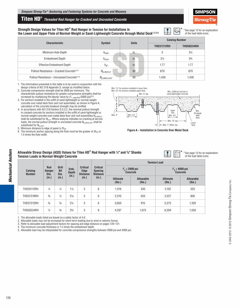
StrengthDesignValuesforTitenHD®RodHangerinTensionforInstallationsintheLowerandUpperFluteofNormal-WeightorSand-LightweightConcretethroughMetalDeck1,2,5,6
Characteristic Symbol UnitsCatalogNumber
THD37212RH THD50234RH
MinimumHoleDepth hhole in. 3 3 1⁄4
EmbedmentDepth hnom in. 2 1⁄2 2 3⁄4
EffectiveEmbedmentDepth hef in. 1.77 1.77
Pullout Resistance – Cracked Concrete2,3,4 Np,deck,cr lbf 870 870
Pullout Resistance – Uncracked Concrete2,3,4 Np,deck,uncr lbf 1,430 1,430
1. The information presented in this table is to be used in conjunction with the designcriteriaofACI318AppendixD,exceptasmodifiedbelow.
2. Concrete compressive strength shall be 3000 psi minimum. The characteristic pullout resistance for greater compressive strengths shall be increased by multiplying the tabular value by (f'c, specified/3000 psi)0.5.
3. For anchors installed in the soffit of sand-lightweight or normal-weight concrete over metal deck floor and roof assemblies, as shown in Figure A, calculation of the concrete breakout strength may be omitted.
4. InaccordancewithACI318SectionD.5.3.2,thenominalpulloutstrengthin cracked concrete for anchors installed in the soffit of sand-lightweight or normal-weight-concrete-over-metal-deck floor and roof assemblies Np,deck,cr shall be substituted for Np,cr. Where analysis indicates no cracking at service loads, the normal pullout strength in uncracked concrete Np,deck,uncr shall be substituted for Np,uncr.
5. Minimum distance to edge of panel is 2hef.6. The minimum anchor spacing along the flute must be the greater of 3hef or
1.5 times the flute width.
AllowableStressDesign(ASD)ValuesforTitenHD®RodHangerwith1⁄4"and3⁄8"ShanksTensionLoadsinNormal-WeightConcrete
CatalogNumber
RodHangerDia.(in.)
DrillBitDia.(in.)
Emb.Depth(in.)
CriticalEdge
Distance(in.)
CriticalSpacingDistance(in.)
TensionLoad
f'c≥2000psiConcrete
f'c≥4000psiConcrete
Ultimate(lbs.)
Allowable(lbs.)
Ultimate(lbs.)
Allowable(lbs.)
THD25112RH 1⁄4 1⁄4 1 1⁄2 3 6 1,319 330 2,102 525
THD37218RH 3⁄8 1⁄4 2 1⁄8 3 6 2,210 555 3,227 805
THD37212RH 3⁄8 3⁄8 2 1⁄2 3 6 3,650 915 5,275 1,320
THD50234RH 1⁄2 3⁄8 2 3⁄4 3 6 4,297 1,075 6,204 1,550
1. The allowable loads listed are based on a safety factor of 4.0.2. Allowable loads may not be increased for short-term loading due to wind or seismic forces.3. Refer to allowable load-adjustment factors for spacing and edge distance on pages 120–121.4. The minimum concrete thickness is 1 1⁄2 times the embedment depth.5. Allowable load may be interpolated for concrete compressive strengths between 2000 psi and 4000 psi.
FigureA–InstallationinConcreteOverMetalDeck
Min. 3,000 psi normal orsand-lightweight concrete
Min.20 gauge
steeldeck
Lowerflute
Upperflute
Min. 12" typ.
Max. 1" offset, typ.
Max. 3" Min. 4½"
Min. 1½" for anchors installed in lower flute.Min. 3¼" for anchors installed upper flute.
Min. ¾" typ.
Min. 4½"
* See page 13 for an explanation of the load table icons
* See page 13 for an explanation of the load table icons
*
*
Simpson Strong-Tie ® Anchoring and Fastening Systems for Concrete and Masonry
C-SA
S-20
12 ©
2012
Sim
pson
Stro
ng-T
ie C
ompa
ny In
c.
126
Titen HD® Threaded Rod Hanger for Cracked and Uncracked Concrete

Mechanical Anchors
TheTitenHD® Rod Coupler is designed to be used in conjunction with a single or multi-story rod tie-down system. This anchor provides a fast and simple way to attach threaded rod to a concrete stem wall or thickened slab footing. Unlike adhesive anchors, the installation requires no special tool, cure time or secondary setting process; just drill a hole and drive the anchor.
FEATURES:
• TheserratedcuttingteethandpatentedthreaddesignenabletheTitenHDRodCoupler to be installed quickly and easily. Less installation time translates to lower installed cost
• Thespecializedheattreatingprocesscreatestiphardnesstofacilitatecuttingwhile the body remain ductile
• Nospecialsettingtoolsarerequired.TheTitenHDRodCouplerinstallswithregular or hammer drill, ANSI size bits and standard sockets
• Compatiblewiththreadedrodsin3⁄8" and 1⁄2" diameters
MATERiAl: Carbon steel, heat treated
FiNiSH: Zinc plated
iNSTAllATiON:
Caution: Oversized holes in the base material will reduce or eliminate the mechanical interlock of the threads with base material and will reduce the anchor’s loadcapacity.UseaTitenHD® Rod Coupler one time only. Installing the anchor multiple times may result in excessive thread wear and reduce load capacity
• Drillaholeusingthespecifieddiametercarbidebitintothebasematerialtoadepth of at least 1⁄2" deeper than the required embedment.
• Blowtheholecleanofdustanddebrisusingcompressedair.Overheadapplication need not be blown clean.
• Tightentheanchorwithappropriatesizesocketuntiltheheadsitsflushagainst base material
TitenHD®RodCouplerProductData
1. Length is measured from the underside of the coupler.
Size1(in)
ModelNo.
AcceptsRodDia.(in.)
DrillBitDia.(in)
WrenchSize(in)
Quantity
Box Carton
3⁄8 x 6 3⁄4 THD37634RC 3⁄8 3⁄8 9⁄16 50 1001⁄2 x 9 3⁄4 THD50934RC 1⁄2 1⁄2 3⁄4 20 40
InstallationSequence
1⁄2" min.
TitenHD®RodCouplerU.S.Patent
5,674,035&6,623,228
Washerrecommended to resistshear loads
1⁄2" min.
Simpson Strong-Tie ® Anchoring and Fastening Systems for Concrete and MasonryC-
SAS-
2012
©20
12 S
imps
on S
trong
-Tie
Com
pany
Inc.
127
Titen HD® Rod Coupler Threaded Rod Anchors for Concrete Foundations

Mec
hani
cal A
ncho
rs
TitenHD®RodCouplerTensionLoadsinNormal-WeightConcreteStemwall
Sizein.
(mm)
DrillBitDia.in.
Embed.Depthin.
(mm)
StemwallWidthin.
(mm)
MinimumEdgeDist.in.
(mm)
MinimumEndDist.in.
(mm)
MinimumSpacingDist.in.
(mm)
TensionLoadBasedon
ConcreteStrength
TensionLoadBasedonConnected
RodStrength
f'c≥2500psi(17.2Mpa)Concrete
A307(SAE1018)
Ultimatelbs.(kN)
Allowablelbs.(kN)
Allowablelbs.(kN)
3⁄8(9.5)
3⁄8 5(127)
8(203)
13⁄4 (44)
10(254)
20(508)
8,900(39.6)
2,225(9.9)
2,105(9.4)
1⁄2(12.7)
1⁄2 8(203)
8(203)
13⁄4(44)
16 (406)
32(813)
15,540(69.1)
3,885(17.3)
3,750(16.7)
TitenHD®RodCouplerShearLoadsinNormal-WeightConcreteStemwall,LoadAppliedParalleltoConcreteEdge
1. Install with a washer (not supplied with anchor) when used to resist shear loads.2. The allowable load based on concrete edge distance is based on a factor of safety of 4.0. Steel strength does not control.3. The minimum concrete thickness is 1.5 times the embedment depth.4. Tension and shear loads may be combined using the straight-line interaction equation (n=1).
Sizein.
(mm)
DrillBitDia.in.
Embed.Depthin.
(mm)
StemwallWidthin.
(mm)
MinimumEdgeDist.in.
(mm)
MinimumEndDist.in.
(mm)
MinimumSpacingDist.in.
(mm)
ShearLoadBasedonConc.EdgeDist.
f'c≥2500psi(17.2Mpa)Concrete
Ultimatelbs.(kN)
Allowablelbs.(kN)
1⁄2(12.7)
1⁄2 8(203)
8(203)
13⁄4(44)
16(406)
32(813)
6,200(27.6)
1,550(6.9)
*
1. Allowable load must be the lesser of the concrete or steel strength.2. The allowable loads based on concrete strength are based on a factor of safety of 4.0.3. The allowable load based on steel strength is limited by the strength of the coupler nut supplied with this anchor. Use of higher strength rod will not increase allowable loads.4. The minimum concrete thickness is 1.5 times the embedment depth.5. Tension and shear loads may be combined using the straight-line interaction equation (n=1).
*See page 13 for an explanation of the load table icons
*
Simpson Strong-Tie ® Anchoring and Fastening Systems for Concrete and Masonry
C-SA
S-20
12 ©
2012
Sim
pson
Stro
ng-T
ie C
ompa
ny In
c.
128
Titen HD® Rod Coupler Threaded Rod Anchors for Concrete Foundations
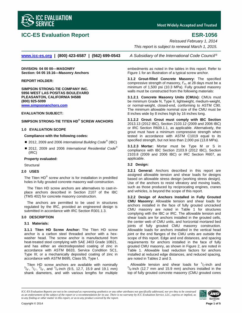
ICC-ES Evaluation Reports are not to be construed as representing aesthetics or any other attributes not specifically addressed, nor are they to be construed as an endorsement of the subject of the report or a recommendation for its use. There is no warranty by ICC Evaluation Service, LLC, express or implied, as to any finding or other matter in this report, or as to any product covered by the report.
Copyright © 2014 Page 1 of 5 1000
ICC-ES Evaluation Report ESR-1056 Reissued February 1, 2014 This report is subject to renewal March 1, 2015.
www.icc-es.org | (800) 423-6587 | (562) 699-0543 A Subsidiary of the International Code Council ®
DIVISION: 04 00 00—MASONRY Section: 04 05 19.16—Masonry Anchors
REPORT HOLDER:
SIMPSON STRONG-TIE COMPANY INC. 5956 WEST LAS POSITAS BOULEVARD PLEASANTON, CALIFORNIA 94588 (800) 925-5099 www.simpsonanchors.com
EVALUATION SUBJECT:
SIMPSON STRONG-TIE TITEN HD® SCREW ANCHORS 1.0 EVALUATION SCOPE
Compliance with the following codes:
2012, 2009 and 2006 International Building Code® (IBC)
2012, 2009 and 2006 International Residential Code® (IRC)
Property evaluated:
Structural
2.0 USES
The Titen HD® screw anchor is for installation in predrilled holes in fully grouted concrete masonry wall construction.
The Titen HD screw anchors are alternatives to cast-in-place anchors described in Section 2107 of the IBC (TMS 402) for concrete masonry construction.
The anchors are permitted to be used in structures regulated by the IRC, provided an engineered design is submitted in accordance with IRC Section R301.1.3.
3.0 DESCRIPTION
3.1 Materials:
3.1.1 Titen HD Screw Anchor: The Titen HD screw anchor is a carbon steel threaded anchor with a hex-washer head. The screw anchor is manufactured from heat-treated steel complying with SAE J403 Grade 10B21, and has either an electrodeposited coating of zinc in accordance with ASTM B633, Service Condition SC1, Type III; or a mechanically deposited coating of zinc in accordance with ASTM B695, Class 55, Type I.
Titen HD screw anchors are available with nominally 3/8-,
1/2-, 5/8-, and 3/4-inch (9.5, 12.7, 15.9 and 19.1 mm)
shank diameters, and with various lengths for multiple
embedments as noted in the tables in this report. Refer to Figure 1 for an illustration of a typical screw anchor.
3.1.2 Grout-filled Concrete Masonry: The specified compressive strength of masonry, f’m, at 28 days must be a minimum of 1,500 psi (10.3 MPa). Fully grouted masonry walls must be constructed from the following materials:
3.1.2.1 Concrete Masonry Units (CMUs): CMUs must be minimum Grade N, Type II, lightweight, medium-weight, or normal-weight, closed-end, conforming to ASTM C90. The minimum allowable nominal size of the CMU must be 8 inches wide by 8 inches high by 16 inches long.
3.1.2.2 Grout: Grout must comply with IBC Section 2013.13 (2012 IBC), Section 2103.12 (2009 and 2006 IBC) or IRC Section R609.1.1, as applicable. Alternatively, the grout must have a minimum compressive strength when tested in accordance with ASTM C1019 equal to its specified strength, but not less than 2,000 psi (13.8 MPa).
3.1.2.3 Mortar: Mortar must be Type M or S in compliance with IBC Section 2103.9 (2012 IBC), Section 2103.8 (2009 and 2006 IBC) or IRC Section R607, as applicable.
3.2 Design:
3.2.1 General: Anchors described in this report are assigned allowable tension and shear loads for designs based on allowable stress design (working stress design). Use of the anchors to resist vibratory and moving loads, such as those produced by reciprocating engines, cranes and vehicles, is beyond the scope of this report.
3.2.2 Design of Anchors Installed in Fully Grouted CMU Masonry: Allowable tension and shear loads for anchors installed in the face of fully grouted uncracked CMU masonry are noted in Table 1 for structures complying with the IBC or IRC. The allowable tension and shear loads are for anchors installed in the grouted cells, the center web of CMU units, and horizontal mortared bed joints of fully grouted CMU masonry construction. Allowable loads for anchors installed in the vertical head joint or the end flanges of the CMU units are outside the scope of this report. Edge and end distances, and spacing requirements for anchors installed in the face of fully grouted CMU masonry, as shown in Figure 2, are noted in Table 1. Allowable load reduction factors for anchors installed at reduced edge distances, and reduced spacing, are noted in Tables 2 and 3.
Allowable tension and shear loads for 1/2-inch and 5/8-inch (12.7 mm and 15.9 mm) anchors installed in the top of fully grouted concrete masonry (CMU grouted cores

ESR-1056 | Most Widely Accepted and Trusted Page 2 of 5
and CMU webs), are noted in Table 4 for anchors installed in structures complying with the IBC or IRC.
Allowable loads for anchors installed in the face of fully grouted CMU masonry walls subjected to combined shear and tension forces must be determined by the following equation:
1.0
where:
Ps = Applied service tension load.
Pt = Allowable service tension load.
Vs = Applied service shear load.
Vt = Allowable service shear load.
4.0 INSTALLATION
Titen HD screw anchors must be installed by drilling a pilot hole into the substrate using a handheld electro-pneumatic rotary hammer drill with a carbide-tipped drill bit conforming to ANSI B212.15-1994. The pilot hole must have the same diameter as the nominal diameter of the anchor. The hole is drilled to the specified embedment depth plus 1/2 inch (12.7 mm). Dust and debris in the hole must be removed by using oil-free compressed air. The Titen HD screw anchor must be installed into the hole to the required embedment using a socket wrench or powered impact wrench.
4.1 Installation in Fully Grouted CMU Masonry: Anchors installed in the face of fully grouted CMU construction must be limited to the face shell of the CMU unit (center web and grouted cores) and the horizontal mortared bed joints, as indicated by the shaded areas in Figure 2. Anchors installed in a T-joint, the mortared head joint, or the end webs of a CMU unit, as indicated in the non-shaded areas in Figure 2, are outside the scope of this report.
For anchors installed in the top of fully grouted concrete masonry (CMU grouted cores and CMU webs), anchor location must comply with the minimum edge and end distances noted in Table 4 and shown in Figure 3. Anchors installed in the mortared head joint are outside the scope of this report.
4.2 Installation with Special Inspection (When Required):
Anchors must be installed with special inspection. For the IBC and IRC, special inspection must conform to Sections 1704 and 1705 of the IBC
For fasteners installed with special inspection, the following items, as applicable, must be inspected: fastener type and dimensions; masonry unit type and compliance with ASMT C90; grout and mortar compressive strengths, and (when required) masonry prism compressive strength; drill bit size and compliance with ANSI B212.15-1994; and fastener embedment, spacing, and edge (and end) distances. The special inspector must inspect and verify that anchor installation complies with this evaluation report and Simpson Strong-Tie Company’s published installation instructions.
5.0 CONDITIONS OF USE
The Titen HD Screw Anchors described in this report comply with, or are suitable alternatives to what is specified in, the codes listed in Section 1.0 of this report, subject to the following conditions:
5.1 Anchors are identified and installed in accordance with this report and the manufacturer’s published installation instructions.
5.2 Anchors installed in the face or the top of fully grouted CMU masonry to resist dead, live, wind, and earthquake load applications must be in accordance with Sections 3.2.1 and 3.2.2.
5.3 Grouted Masonry under IBC or IRC: The anchors described in the evaluation report are capable of resisting seismic and wind loads. When using the basic load combinations in accordance with IBC Section 1605.3.1, allowable loads are not permitted to be increased for seismic or wind loading. When using the alternative basic load combinations in IBC Section 1605.3.2 that include seismic or wind loads, the allowable shear and tension loads for anchors are permitted to be increased by 331/3 percent, or the alternative basic load combinations may be multiplied by a factor of 0.75. The allowable stress increase or load reduction is not permitted under 2012 codes.
5.4 Fatigue and Shock Loading: Since an ICC-ES acceptance criteria is evaluating data to determine the performance of screw anchors subjected to fatigue or shock loading is unavailable at this time, the use of these anchors under these conditions is beyond the scope of this report.
5.5 Fire-resistive Construction: Where not otherwise prohibited by the applicable code, anchors are permitted for use with fire-resistance-rated construction provided that at least one of the following conditions is fulfilled.
Anchors are used to resist wind or seismic forces only.
Anchors that support fire-resistance-rated construction or gravity load-bearing structural elements are within a fire-resistance-rated envelope or a fire-resistance-rated membrane, are protected by approved fire-resistance-rated materials, or have been evaluated for resistance to fire exposure in accordance with recognized standards.
Anchors are used to support nonstructural elements.
5.6 Cracked Masonry: Since an ICC-ES acceptance criteria for evaluating the performance of screw anchors in cracked masonry is unavailable at this time, the use of anchors is limited to installation in uncracked masonry. Cracking occurs when ft fr due to service loads or deformations.
5.7 Anchors are installed in substrates in holes predrilled with carbide-tipped masonry drill bits complying with ANSI B212.15-1994, and having the same diameter as the nominal diameter of the anchor.
5.8 Calculations demonstrating that the applied loads are less than the allowable loads described in this report, must be submitted to the building official. The calculations must be prepared by a registered design professional where required by the statutes of the jurisdiction in which the project is to be constructed.
5.9 Special inspection, when required, must be provided in accordance with Section 4.2.
5.10 Anchors are limited to dry, interior use.

ESR-1056 | Most Widely Accepted and Trusted Page 3 of 5
5.11 The Titen HD screw anchors are manufactured by Simpson Strong-Tie Company under a quality control program with inspections by ICC-ES.
6.0 EVIDENCE SUBMITTED
Data in accordance with the ICC-ES Acceptance Criteria for Predrilled Fasteners (Screw Anchors) in Masonry (AC106), dated May 2012, including the following optional tests:
6.1 Anchors installed in the face of fully grouted CMU masonry wall construction: Effects of edge distance on tension and shear performance (Test Series 4, 5, 13, and 14 of AC106), and seismic performance tests (Section 4.6 of AC106).
6.2 Anchors installed in the top of fully grouted CMU masonry wall construction with a minimum 13/4-inch (44 mm) edge distance: Effects on tension and shear performance (Test Series 4 and 13 of AC106), and seismic performance tests (Section 4.6 of AC106).
7.0 IDENTIFICATION
Titen HD screw anchor packaging is marked with the Simpson Strong-Tie Company name; product name (Titen HD); anchor diameter and length; and the evaluation report number (ESR-1056). In addition, the ≠ symbol and anchor length (in inches) is stamped on the head of each screw anchor.
TABLE 1—IBC AND IRC ALLOWABLE TENSION AND SHEAR LOADS FOR TITEN HD SCREW ANCHORS INSTALLED IN THE FACE OF FULLY GROUTED CMU MASONRY CONSTRUCTION1
ANCHOR DIA.2 (in.)
DRILL BIT DIA. (in.)
MIN. EMBED.3
(in.)
ANCHOR LOCATION4 (in.) ALLOWABLE LOADS BASED ON ANCHORS INSTALLED AT DISTANCES ≥
CRITICAL EDGE DISTANCE, ccrit, AND SPACING, scrit
5,6 (lbf)
Edge Distance Spacing
Tension Shear Critical,
ccrit Minimum,
cmin Critical,
scrit Minimum,
smin
3/8 3/8 23/4 12 4 6 3 480 870
1/2 1/2 31/2 12 4 8 4 690 1,385
5/8 5/8 41/2 12 4 10 5 1,060 2,085
3/4 3/4 51/2 12 4 12 6 1,600 3,000
For SI: 1 inch = 25.4 mm, 1 psi = 6.89 kPa, 1 lbf = 4.48 N.
1Anchors must be installed a minimum of 11/4 inches from vertical head joints and T-joints. Refer to Figure 2 for permitted and prohibited anchor installation locations. 2The drill bit diameter must be equal to the nominal diameter of the anchor. Anchor installation –must comply with Section 4.0 of this report. 3Embedment depth is measured from the outside face of the masonry. 4Critical and minimum edge distances, ccrit and cmin, respectively, must comply with this table. Refer to Figure 2. Critical and minimum spacing, scrit and smin, respectively, must comply with this table. Critical and minimum edge and spacing distances are valid for anchors resisting tension or shear loads. Refer to Table 2 for allowable tension and shear load reduction factors for anchors installed between critical and minimum edge distances, and to Table 3 for anchors installed between critical and minimum spacing. 5Tabulated allowable loads are based on a safety factor of 5.0 6For wind or earthquake loading conditions under 2009 and 2006 codes, allowable loads may be adjusted in accordance with Section 5.3.

ESR-1056 | Most Widely Accepted and Trusted Page 4 of 5
TABLE 2—LOAD REDUCTION FACTORS FOR TITEN HD SCREW ANCHORS INSTALLED BETWEEN CRITICAL AND MINIMUM EDGE DISTANCES (Anchors Installed in the Face of Grout-filled CMU Masonry)1,2,3
ANCHOR DIAMETER (in)
MINIMUM EMBEDMENT
DEPTH (in)
LOAD REDUCTION FACTORS FOR ANCHORS INSTALLED AT: Critical Edge Distance, ccrit
Minimum Edge Distance, cmin
Tension or Shear Load
Tension Load Shear Load Acting:
Towards an Edge
Away from an Edge
Parallel to an Edge
3/8 23/4 1.0 1.0 0.58 0.89 0.77 1/2 31/2 1.0 1.0 0.38 0.79 0.48 5/8 41/2 1.0 0.83 0.30 0.58 0.46 3/4 51/2 1.0 0.66 0.21 0.38 0.44
For SI: 1 inch = 25.4 mm. 1The load reduction factors in this table are applicable to the allowable loads shown in Table 1. 2Reduction factors are cumulative. Multiple reduction factors for more than one spacing or edge distance are calculated separately and multiplied. 3Load reduction factors for anchors loaded in tension or shear with edge distances between critical and minimum are obtained by linear interpolation.
TABLE 3—LOAD REDUCTION FACTORS FOR TITEN HD SCREW ANCHORS INSTALLED BETWEEN CRITICAL AND MINIMUM SPACING (Anchors Installed in the Face of Grout-filled CMU Masonry)1,2,3
ANCHOR DIAMETER (in)
MINIMUM EMBEDMENT DEPTH (in)
LOAD REDUCTION FACTORS FOR ANCHORS INSTALLED AT: Critical Spacing, scrit Minimum Spacing, smin
Tension or Shear Load Tension Load Shear Load 3/8 23/4 1.0 0.87 0.62 1/2 31/2 1.0 0.69 0.62 5/8 41/2 1.0 0.59 0.62 3/4 51/2 1.0 0.50 0.62
For SI: 1 inch = 25.4 mm. 1The load reduction factors in this table are applicable to the allowable loads shown in Table 1. 2Reduction factors are cumulative. Multiple reduction factors for more than one spacing or edge distance are calculated separately and multiplied. 3Load reduction factors for anchors loaded in tension or shear with spacing between critical and minimum are obtained by linear interpolation.

ESR-1056 | Most Widely Accepted and Trusted Page 5 of 5
TABLE 4—IBC AND IRC ALLOWABLE TENSION AND SHEAR LOADS FOR TITEN HD SCREW ANCHORS INSTALLED IN TOP OF GROUT-FILLED CMU MASONRY1
ANCHOR DIA. (in)
DRILL BIT DIA. (in)
MINIMUM EMBEDMENT
DEPTH (in)
ANCHOR LOCATION2 (in) IBC AND IRC ALLOWABLE LOADS3,4 (lbf)
Minimum Edge
Distance
Minimum End
Distance
Minimum Spacing
Tension
Shear Parallel to
Edge of Masonry
Wall
Perpendicular to Edge of
Masonry Wall 1/2
1/2 41/2 13/4 8 8 570 585 160 5/8
5/8 41/2 13/4 10 10 570 675 160
For SI: 1 inch = 25.4 mm, 1 pound = 4.45 N, 1 psi = 6.89 kPa. 1The allowable tension and shear loads in Table 4 are applicable when anchors are installed in structures regulated by the IRC or IBC. 2Minimum edge and end distances are measured from the anchor centerline to the edge and end of the CMU masonry wall, respectively. Refer to Figure 3 Minimum spacing is measured from center-to-center of two anchors. Anchors installed in the mortared head joint are outside the scope of this report. 3The allowable loads in Table 4 are for anchors resisting dead, live, wind, and earthquake load applications. For short-term loading due to wind and earthquake forces under 2006 and 2009 codes, the allowable loads may be adjusted in accordance with Section 5.3. 4Allowable tension and shear loads are based on a safety factor of 5.0.

BOARD OF
BUILDING AND SAFETY COMMISSIONERS
___
VAN AMBATIELOS PRESIDENT
E. FELICIA BRANNON VICE-PRESIDENT
JOSELYN GEAGA-ROSENTHAL
GEORGE HOVAGUIMIAN
JAVIER NUNEZ ___
CITY OF LOS ANGELES CALIFORNIA
ERIC GARCETTI MAYOR
DEPARTMENT OF
BUILDING AND SAFETY 201 NORTH FIGUEROA STREET
LOS ANGELES, CA 90012
____
RAYMOND S. CHAN, C.E., S.E.
GENERAL MANAGER
FRANK BUSH
EXECUTIVE OFFICER
____
RR 25560 Page 1 of 3
LADBS G-5 (Rev.04/30/14) AN EQUAL EMPLOYMENT OPPORTUNITY - AFFIRMATIVE ACTION EMPLOYER
Simpson Strong-Tie Co., Inc. RESEARCH REPORT: RR 25560 12246 Holly St (CSI # 04 06 19.16) Riverside, CA 92509 BASED UPON ICC-ES EVALUATION Attn: Jason Oakley P.E. SERVICE REPORT No. ESR-1056 (714) 448-9143 REEVALUATION DUE
DATE: July 1, 2015 Issued Date: September 1, 2014 Code: 2014 LABC GENERAL APPROVAL – Clerical Modification - Titen HD Masonry Screw Anchors.
DETAILS The above assemblies and products are approved when in compliance with the description, use, identification and findings of Report No. ESR-1056 reissued February 1, 2014 of the ICC Evaluation Service, Incorporated. The report, in its entirety, is attached and made part of this general approval. The parts of Report No. ESR-1056 marked by the asterisks has been removed by the Los Angeles Building Department from this approval. The approval is subject to the following conditions: 1. The values shown in this report shall not be used in repair, retrofit and new construction
of tilt-up wall anchorage (in tension) for the connection with the horizontal wood diaphragm.
2. A 25% reduction in all allowable loads specified in the research report shall be taken in
hold-down devices as required by the 2014 Los Angeles City Building Code. 3. The anchors shall not be used in cracked masonry.
Simpson Strong-Tie Co., Inc. Re: Titen HD Concrete Screw Anchors
RR 25560 Page 2 of 3
4. Anchors are identified and installed in accordance with this report and the manufacturer’s published installation instructions.
5. Design of Titen HD Screw Anchors installed in the face of fully grouted concrete
masonry construction to resist dead, live, wind and earthquake load applications shall be in accordance with Sections 3.2 of ESR-1056.
6. Anchors shall be installed in accordance with Section 4.0 of ESR-1056 and the holes for
the anchors shall be predrilled with carbide-tipped masonry drill bits complying with ANSI B212.15-1994 into the approved substrate, and have the same diameter as the nominal diameter of the anchor.
7. Calculations demonstrating that the applied loads are less than the allowable loads
described in this report shall be submitted to the plan check Engineer at the time of permit application. The calculations shall be prepared by a Civil or Structural Engineer registered in the State of California.
8. Special inspection shall be provided in accordance with Section 1705 of the 2014 Los
Angeles Building Code. 9. Anchors shall be limited to dry and interior use. 10. Each anchor shall bear a permanent identification indicating the manufacturer's name or
symbol and product designation. 11. The anchors shall be installed per the manufacturer's instructions, except as otherwise
stated in this report. A copy of this research report and the installation instructions shall be available at each job site.
12. Anchors are limited to non fire-resistive construction except for anchors that resist wind
or seismic load only. 13. The grout shall have attained its minimum design strength prior to installation of the
anchors.
DISCUSSION The Clerical Modification is to update the report to the 2014 Los Angeles Building Code. The approval is based on tests in accordance with ICC ES Acceptance Criteria for Predrilled Fastener (Screw Anchors) in Masonry (AC 106), dated December 2007. This general approval of an equivalent alternate to the Code is only valid where an engineer and/or inspector of this Department has determined that all conditions of this approval have been met in the project in which it is to be used.
Simpson Strong-Tie Co., Inc. Re: Titen HD Concrete Screw Anchors
RR 25560 Page 3 of 3
This general approval will remain effective provided the Evaluation Report is maintained valid and unrevised with the issuing organization. Any revisions to the report must be submitted to this Department, with appropriate fee, for review in order to continue the approval of the revised report. Addressee to whom this Research Report is issued is responsible for providing copies of it, complete with any attachments indicated, to architects, engineers and builders using items approved herein in design or construction which must be approved by Department of Building and Safety Engineers and Inspectors. ____________________________________ ALLEN PEERY, Chief Engineering Research Section 201 N. Figueroa St., Room 880 Los Angeles, CA 90012 Phone- 213-202-9812 Fax- 213-202-9943 JD:jd RR25560/MSWord2010 R106/18/14 5A1/2103.4 Attachment: ICC ES Report No. ESR-1056 (6 Pages)

ICC-ES Evaluation Reports are not to be construed as representing aesthetics or any other attributes not specifically addressed, nor are they to be construed as an endorsement of the subject of the report or a recommendation for its use. There is no warranty by ICC Evaluation Service, LLC, express or implied, as to any finding or other matter in this report, or as to any product covered by the report.
Copyright © 2014 Page 1 of 5 1000
ICC-ES Evaluation Report ESR-1056 Reissued February 1, 2014 This report is subject to renewal March 1, 2015.
www.icc-es.org | (800) 423-6587 | (562) 699-0543 A Subsidiary of the International Code Council ®
DIVISION: 04 00 00—MASONRY Section: 04 05 19.16—Masonry Anchors
REPORT HOLDER:
SIMPSON STRONG-TIE COMPANY INC. 5956 WEST LAS POSITAS BOULEVARD PLEASANTON, CALIFORNIA 94588 (800) 925-5099 www.simpsonanchors.com
EVALUATION SUBJECT:
SIMPSON STRONG-TIE TITEN HD® SCREW ANCHORS 1.0 EVALUATION SCOPE
Compliance with the following codes:
2012, 2009 and 2006 International Building Code® (IBC)
2012, 2009 and 2006 International Residential Code® (IRC)
Property evaluated:
Structural
2.0 USES
The Titen HD® screw anchor is for installation in predrilled holes in fully grouted concrete masonry wall construction.
The Titen HD screw anchors are alternatives to cast-in-place anchors described in Section 2107 of the IBC (TMS 402) for concrete masonry construction.
The anchors are permitted to be used in structures regulated by the IRC, provided an engineered design is submitted in accordance with IRC Section R301.1.3.
3.0 DESCRIPTION
3.1 Materials:
3.1.1 Titen HD Screw Anchor: The Titen HD screw anchor is a carbon steel threaded anchor with a hex-washer head. The screw anchor is manufactured from heat-treated steel complying with SAE J403 Grade 10B21, and has either an electrodeposited coating of zinc in accordance with ASTM B633, Service Condition SC1, Type III; or a mechanically deposited coating of zinc in accordance with ASTM B695, Class 55, Type I.
Titen HD screw anchors are available with nominally 3/8-,
1/2-, 5/8-, and 3/4-inch (9.5, 12.7, 15.9 and 19.1 mm)
shank diameters, and with various lengths for multiple
embedments as noted in the tables in this report. Refer to Figure 1 for an illustration of a typical screw anchor.
3.1.2 Grout-filled Concrete Masonry: The specified compressive strength of masonry, f’m, at 28 days must be a minimum of 1,500 psi (10.3 MPa). Fully grouted masonry walls must be constructed from the following materials:
3.1.2.1 Concrete Masonry Units (CMUs): CMUs must be minimum Grade N, Type II, lightweight, medium-weight, or normal-weight, closed-end, conforming to ASTM C90. The minimum allowable nominal size of the CMU must be 8 inches wide by 8 inches high by 16 inches long.
3.1.2.2 Grout: Grout must comply with IBC Section 2013.13 (2012 IBC), Section 2103.12 (2009 and 2006 IBC) or IRC Section R609.1.1, as applicable. Alternatively, the grout must have a minimum compressive strength when tested in accordance with ASTM C1019 equal to its specified strength, but not less than 2,000 psi (13.8 MPa).
3.1.2.3 Mortar: Mortar must be Type M or S in compliance with IBC Section 2103.9 (2012 IBC), Section 2103.8 (2009 and 2006 IBC) or IRC Section R607, as applicable.
3.2 Design:
3.2.1 General: Anchors described in this report are assigned allowable tension and shear loads for designs based on allowable stress design (working stress design). Use of the anchors to resist vibratory and moving loads, such as those produced by reciprocating engines, cranes and vehicles, is beyond the scope of this report.
3.2.2 Design of Anchors Installed in Fully Grouted CMU Masonry: Allowable tension and shear loads for anchors installed in the face of fully grouted uncracked CMU masonry are noted in Table 1 for structures complying with the IBC or IRC. The allowable tension and shear loads are for anchors installed in the grouted cells, the center web of CMU units, and horizontal mortared bed joints of fully grouted CMU masonry construction. Allowable loads for anchors installed in the vertical head joint or the end flanges of the CMU units are outside the scope of this report. Edge and end distances, and spacing requirements for anchors installed in the face of fully grouted CMU masonry, as shown in Figure 2, are noted in Table 1. Allowable load reduction factors for anchors installed at reduced edge distances, and reduced spacing, are noted in Tables 2 and 3.
Allowable tension and shear loads for 1/2-inch and 5/8-inch (12.7 mm and 15.9 mm) anchors installed in the top of fully grouted concrete masonry (CMU grouted cores
37203
Typewritten Text
*
37203
Cross-Out
37203
Typewritten Text
*
37203
Typewritten Text
37203
Typewritten Text
Deleted by the City of Los Angeles

ESR-1056 | Most Widely Accepted and Trusted Page 2 of 5
and CMU webs), are noted in Table 4 for anchors installed in structures complying with the IBC or IRC.
Allowable loads for anchors installed in the face of fully grouted CMU masonry walls subjected to combined shear and tension forces must be determined by the following equation:
1.0
where:
Ps = Applied service tension load.
Pt = Allowable service tension load.
Vs = Applied service shear load.
Vt = Allowable service shear load.
4.0 INSTALLATION
Titen HD screw anchors must be installed by drilling a pilot hole into the substrate using a handheld electro-pneumatic rotary hammer drill with a carbide-tipped drill bit conforming to ANSI B212.15-1994. The pilot hole must have the same diameter as the nominal diameter of the anchor. The hole is drilled to the specified embedment depth plus 1/2 inch (12.7 mm). Dust and debris in the hole must be removed by using oil-free compressed air. The Titen HD screw anchor must be installed into the hole to the required embedment using a socket wrench or powered impact wrench.
4.1 Installation in Fully Grouted CMU Masonry: Anchors installed in the face of fully grouted CMU construction must be limited to the face shell of the CMU unit (center web and grouted cores) and the horizontal mortared bed joints, as indicated by the shaded areas in Figure 2. Anchors installed in a T-joint, the mortared head joint, or the end webs of a CMU unit, as indicated in the non-shaded areas in Figure 2, are outside the scope of this report.
For anchors installed in the top of fully grouted concrete masonry (CMU grouted cores and CMU webs), anchor location must comply with the minimum edge and end distances noted in Table 4 and shown in Figure 3. Anchors installed in the mortared head joint are outside the scope of this report.
4.2 Installation with Special Inspection (When Required):
Anchors must be installed with special inspection. For the IBC and IRC, special inspection must conform to Sections 1704 and 1705 of the IBC
For fasteners installed with special inspection, the following items, as applicable, must be inspected: fastener type and dimensions; masonry unit type and compliance with ASMT C90; grout and mortar compressive strengths, and (when required) masonry prism compressive strength; drill bit size and compliance with ANSI B212.15-1994; and fastener embedment, spacing, and edge (and end) distances. The special inspector must inspect and verify that anchor installation complies with this evaluation report and Simpson Strong-Tie Company’s published installation instructions.
5.0 CONDITIONS OF USE
The Titen HD Screw Anchors described in this report comply with, or are suitable alternatives to what is specified in, the codes listed in Section 1.0 of this report, subject to the following conditions:
5.1 Anchors are identified and installed in accordance with this report and the manufacturer’s published installation instructions.
5.2 Anchors installed in the face or the top of fully grouted CMU masonry to resist dead, live, wind, and earthquake load applications must be in accordance with Sections 3.2.1 and 3.2.2.
5.3 Grouted Masonry under IBC or IRC: The anchors described in the evaluation report are capable of resisting seismic and wind loads. When using the basic load combinations in accordance with IBC Section 1605.3.1, allowable loads are not permitted to be increased for seismic or wind loading. When using the alternative basic load combinations in IBC Section 1605.3.2 that include seismic or wind loads, the allowable shear and tension loads for anchors are permitted to be increased by 331/3 percent, or the alternative basic load combinations may be multiplied by a factor of 0.75. The allowable stress increase or load reduction is not permitted under 2012 codes.
5.4 Fatigue and Shock Loading: Since an ICC-ES acceptance criteria is evaluating data to determine the performance of screw anchors subjected to fatigue or shock loading is unavailable at this time, the use of these anchors under these conditions is beyond the scope of this report.
5.5 Fire-resistive Construction: Where not otherwise prohibited by the applicable code, anchors are permitted for use with fire-resistance-rated construction provided that at least one of the following conditions is fulfilled.
Anchors are used to resist wind or seismic forces only.
Anchors that support fire-resistance-rated construction or gravity load-bearing structural elements are within a fire-resistance-rated envelope or a fire-resistance-rated membrane, are protected by approved fire-resistance-rated materials, or have been evaluated for resistance to fire exposure in accordance with recognized standards.
Anchors are used to support nonstructural elements.
5.6 Cracked Masonry: Since an ICC-ES acceptance criteria for evaluating the performance of screw anchors in cracked masonry is unavailable at this time, the use of anchors is limited to installation in uncracked masonry. Cracking occurs when ft fr due to service loads or deformations.
5.7 Anchors are installed in substrates in holes predrilled with carbide-tipped masonry drill bits complying with ANSI B212.15-1994, and having the same diameter as the nominal diameter of the anchor.
5.8 Calculations demonstrating that the applied loads are less than the allowable loads described in this report, must be submitted to the building official. The calculations must be prepared by a registered design professional where required by the statutes of the jurisdiction in which the project is to be constructed.
5.9 Special inspection, when required, must be provided in accordance with Section 4.2.
5.10 Anchors are limited to dry, interior use.
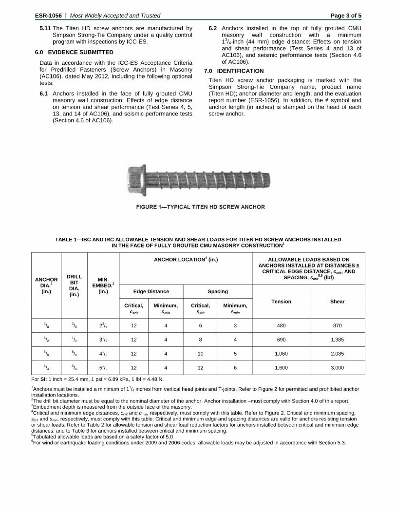
ESR-1056 | Most Widely Accepted and Trusted Page 3 of 5
5.11 The Titen HD screw anchors are manufactured by Simpson Strong-Tie Company under a quality control program with inspections by ICC-ES.
6.0 EVIDENCE SUBMITTED
Data in accordance with the ICC-ES Acceptance Criteria for Predrilled Fasteners (Screw Anchors) in Masonry (AC106), dated May 2012, including the following optional tests:
6.1 Anchors installed in the face of fully grouted CMU masonry wall construction: Effects of edge distance on tension and shear performance (Test Series 4, 5, 13, and 14 of AC106), and seismic performance tests (Section 4.6 of AC106).
6.2 Anchors installed in the top of fully grouted CMU masonry wall construction with a minimum 13/4-inch (44 mm) edge distance: Effects on tension and shear performance (Test Series 4 and 13 of AC106), and seismic performance tests (Section 4.6 of AC106).
7.0 IDENTIFICATION
Titen HD screw anchor packaging is marked with the Simpson Strong-Tie Company name; product name (Titen HD); anchor diameter and length; and the evaluation report number (ESR-1056). In addition, the ≠ symbol and anchor length (in inches) is stamped on the head of each screw anchor.
TABLE 1—IBC AND IRC ALLOWABLE TENSION AND SHEAR LOADS FOR TITEN HD SCREW ANCHORS INSTALLED IN THE FACE OF FULLY GROUTED CMU MASONRY CONSTRUCTION1
ANCHOR DIA.2 (in.)
DRILL BIT DIA. (in.)
MIN. EMBED.3
(in.)
ANCHOR LOCATION4 (in.) ALLOWABLE LOADS BASED ON ANCHORS INSTALLED AT DISTANCES ≥
CRITICAL EDGE DISTANCE, ccrit, AND SPACING, scrit
5,6 (lbf)
Edge Distance Spacing
Tension Shear Critical,
ccrit Minimum,
cmin Critical,
scrit Minimum,
smin
3/8 3/8 23/4 12 4 6 3 480 870
1/2 1/2 31/2 12 4 8 4 690 1,385
5/8 5/8 41/2 12 4 10 5 1,060 2,085
3/4 3/4 51/2 12 4 12 6 1,600 3,000
For SI: 1 inch = 25.4 mm, 1 psi = 6.89 kPa, 1 lbf = 4.48 N.
1Anchors must be installed a minimum of 11/4 inches from vertical head joints and T-joints. Refer to Figure 2 for permitted and prohibited anchor installation locations. 2The drill bit diameter must be equal to the nominal diameter of the anchor. Anchor installation –must comply with Section 4.0 of this report. 3Embedment depth is measured from the outside face of the masonry. 4Critical and minimum edge distances, ccrit and cmin, respectively, must comply with this table. Refer to Figure 2. Critical and minimum spacing, scrit and smin, respectively, must comply with this table. Critical and minimum edge and spacing distances are valid for anchors resisting tension or shear loads. Refer to Table 2 for allowable tension and shear load reduction factors for anchors installed between critical and minimum edge distances, and to Table 3 for anchors installed between critical and minimum spacing. 5Tabulated allowable loads are based on a safety factor of 5.0 6For wind or earthquake loading conditions under 2009 and 2006 codes, allowable loads may be adjusted in accordance with Section 5.3.
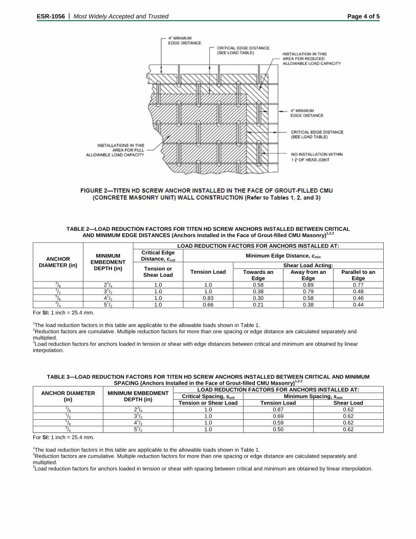
ESR-1056 | Most Widely Accepted and Trusted Page 4 of 5
TABLE 2—LOAD REDUCTION FACTORS FOR TITEN HD SCREW ANCHORS INSTALLED BETWEEN CRITICAL AND MINIMUM EDGE DISTANCES (Anchors Installed in the Face of Grout-filled CMU Masonry)1,2,3
ANCHOR DIAMETER (in)
MINIMUM EMBEDMENT
DEPTH (in)
LOAD REDUCTION FACTORS FOR ANCHORS INSTALLED AT: Critical Edge Distance, ccrit
Minimum Edge Distance, cmin
Tension or Shear Load
Tension Load Shear Load Acting:
Towards an Edge
Away from an Edge
Parallel to an Edge
3/8 23/4 1.0 1.0 0.58 0.89 0.77 1/2 31/2 1.0 1.0 0.38 0.79 0.48 5/8 41/2 1.0 0.83 0.30 0.58 0.46 3/4 51/2 1.0 0.66 0.21 0.38 0.44
For SI: 1 inch = 25.4 mm. 1The load reduction factors in this table are applicable to the allowable loads shown in Table 1. 2Reduction factors are cumulative. Multiple reduction factors for more than one spacing or edge distance are calculated separately and multiplied. 3Load reduction factors for anchors loaded in tension or shear with edge distances between critical and minimum are obtained by linear interpolation.
TABLE 3—LOAD REDUCTION FACTORS FOR TITEN HD SCREW ANCHORS INSTALLED BETWEEN CRITICAL AND MINIMUM SPACING (Anchors Installed in the Face of Grout-filled CMU Masonry)1,2,3
ANCHOR DIAMETER (in)
MINIMUM EMBEDMENT DEPTH (in)
LOAD REDUCTION FACTORS FOR ANCHORS INSTALLED AT: Critical Spacing, scrit Minimum Spacing, smin
Tension or Shear Load Tension Load Shear Load 3/8 23/4 1.0 0.87 0.62 1/2 31/2 1.0 0.69 0.62 5/8 41/2 1.0 0.59 0.62 3/4 51/2 1.0 0.50 0.62
For SI: 1 inch = 25.4 mm. 1The load reduction factors in this table are applicable to the allowable loads shown in Table 1. 2Reduction factors are cumulative. Multiple reduction factors for more than one spacing or edge distance are calculated separately and multiplied. 3Load reduction factors for anchors loaded in tension or shear with spacing between critical and minimum are obtained by linear interpolation.
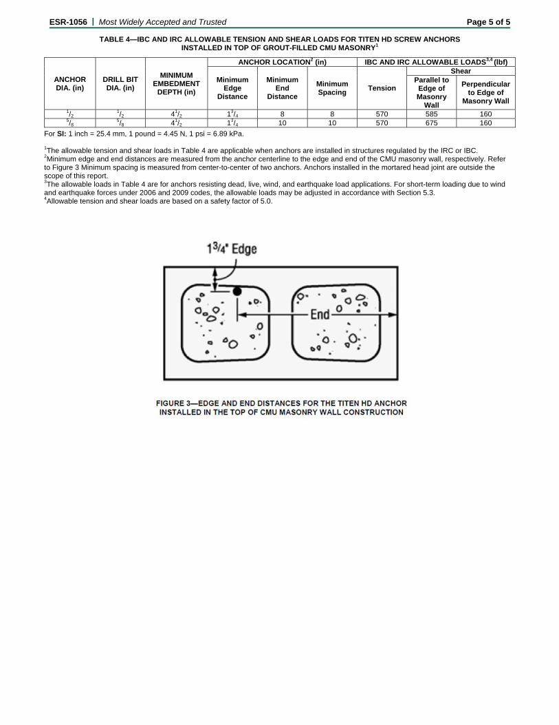
ESR-1056 | Most Widely Accepted and Trusted Page 5 of 5
TABLE 4—IBC AND IRC ALLOWABLE TENSION AND SHEAR LOADS FOR TITEN HD SCREW ANCHORS INSTALLED IN TOP OF GROUT-FILLED CMU MASONRY1
ANCHOR DIA. (in)
DRILL BIT DIA. (in)
MINIMUM EMBEDMENT
DEPTH (in)
ANCHOR LOCATION2 (in) IBC AND IRC ALLOWABLE LOADS3,4 (lbf)
Minimum Edge
Distance
Minimum End
Distance
Minimum Spacing
Tension
Shear Parallel to
Edge of Masonry
Wall
Perpendicular to Edge of
Masonry Wall 1/2
1/2 41/2 13/4 8 8 570 585 160 5/8
5/8 41/2 13/4 10 10 570 675 160
For SI: 1 inch = 25.4 mm, 1 pound = 4.45 N, 1 psi = 6.89 kPa. 1The allowable tension and shear loads in Table 4 are applicable when anchors are installed in structures regulated by the IRC or IBC. 2Minimum edge and end distances are measured from the anchor centerline to the edge and end of the CMU masonry wall, respectively. Refer to Figure 3 Minimum spacing is measured from center-to-center of two anchors. Anchors installed in the mortared head joint are outside the scope of this report. 3The allowable loads in Table 4 are for anchors resisting dead, live, wind, and earthquake load applications. For short-term loading due to wind and earthquake forces under 2006 and 2009 codes, the allowable loads may be adjusted in accordance with Section 5.3. 4Allowable tension and shear loads are based on a safety factor of 5.0.
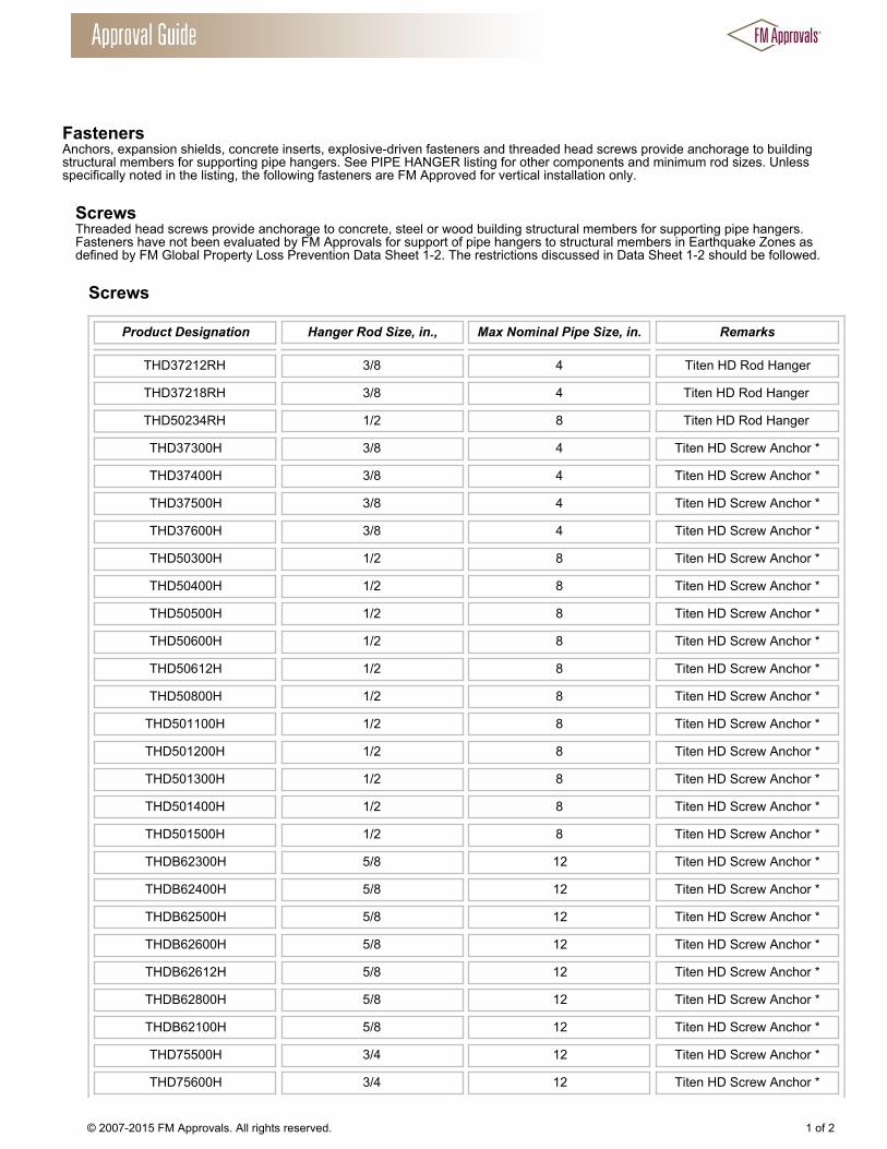
Fasteners Anchors, expansion shields, concrete inserts, explosive-driven fasteners and threaded head screws provide anchorage to buildingstructural members for supporting pipe hangers. See PIPE HANGER listing for other components and minimum rod sizes. Unlessspecifically noted in the listing, the following fasteners are FM Approved for vertical installation only.
Screws Threaded head screws provide anchorage to concrete, steel or wood building structural members for supporting pipe hangers.Fasteners have not been evaluated by FM Approvals for support of pipe hangers to structural members in Earthquake Zones asdefined by FM Global Property Loss Prevention Data Sheet 1-2. The restrictions discussed in Data Sheet 1-2 should be followed.
Screws
Product Designation Hanger Rod Size, in., Max Nominal Pipe Size, in. Remarks
THD37212RH 3/8 4 Titen HD Rod Hanger
THD37218RH 3/8 4 Titen HD Rod Hanger
THD50234RH 1/2 8 Titen HD Rod Hanger
THD37300H 3/8 4 Titen HD Screw Anchor *
THD37400H 3/8 4 Titen HD Screw Anchor *
THD37500H 3/8 4 Titen HD Screw Anchor *
THD37600H 3/8 4 Titen HD Screw Anchor *
THD50300H 1/2 8 Titen HD Screw Anchor *
THD50400H 1/2 8 Titen HD Screw Anchor *
THD50500H 1/2 8 Titen HD Screw Anchor *
THD50600H 1/2 8 Titen HD Screw Anchor *
THD50612H 1/2 8 Titen HD Screw Anchor *
THD50800H 1/2 8 Titen HD Screw Anchor *
THD501100H 1/2 8 Titen HD Screw Anchor *
THD501200H 1/2 8 Titen HD Screw Anchor *
THD501300H 1/2 8 Titen HD Screw Anchor *
THD501400H 1/2 8 Titen HD Screw Anchor *
THD501500H 1/2 8 Titen HD Screw Anchor *
THDB62300H 5/8 12 Titen HD Screw Anchor *
THDB62400H 5/8 12 Titen HD Screw Anchor *
THDB62500H 5/8 12 Titen HD Screw Anchor *
THDB62600H 5/8 12 Titen HD Screw Anchor *
THDB62612H 5/8 12 Titen HD Screw Anchor *
THDB62800H 5/8 12 Titen HD Screw Anchor *
THDB62100H 5/8 12 Titen HD Screw Anchor *
THD75500H 3/4 12 Titen HD Screw Anchor *
THD75600H 3/4 12 Titen HD Screw Anchor *
© 2007-2015 FM Approvals. All rights reserved. 1 of 2

THD75700H 3/4 12 Titen HD Screw Anchor *
THD75812H 3/4 12 Titen HD Screw Anchor *
THD75100H 3/4 12 Titen HD Screw Anchor *
Product Designation Description
THD Titen Heavy Duty
B Latest Design Iteration of 5/8” THD
H Hex Head
MG Mechanically Galvanized
RH Rod Hanger Head
Example: Product Designation Description
THD37218RH 37: 3/8 in. size
218: 2-1/8 in. long
*Available in zinc plated carbon steel or galvanized carbon steel.
Company Name: Simpson Strong-Tie Co Inc
Company Address: 5956 W Las Positas Blvd, Pleasanton, California 94588, USA
Company Website: http://www.strongtie.com/
New/Updated Product Listing: No
Listing Country: United States of America
Certification Type: FM Approved
© 2007-2015 FM Approvals. All rights reserved. 2 of 2

Mechanical Anchors
SAFETY DATA SHEET
Mechanical Anchors Page 1 of 5 SDS North America
1. IDENTIFICATION
Product Identifier: Retrofit Bolt, Blue Banger Hanger®, Crimp Anchor, Drop-In Anchor, Easy-Set
Expansion Anchor, Heli-Tie®
Helical Wall Tie, Hollow Wall Anchor, IXP™ Anchor,
Lag Screw Expansion Shield, Machine Screw Anchor, Nailon Pin Drive Anchor,
Plastic Screw Anchor, Sleeve-All®
Anchor, Split Drive Anchor, Spring Wing Toggle
Bolt, Strong-Bolt™ Wedge Anchor, Strong-Bolt™ 2 Wedge Anchor, Sure Wall
Drywall Anchor/Toggle, Titen®
Screw, Titen HD® Anchor, Torq-Cut™ Anchor,
Wedge-All® Anchor
Recommended Use: Mechanical Anchor
Use Restrictions: None known.
Company: Simpson Strong-Tie Company Inc.
Address: 5956 W. Las Positas Blvd.
Pleasanton, CA 94588, USA
Phone: 1-800-999-5099
Website: www.strongtie.com
Emergency: 1-800-535-5053 (US/Canada)
1-352-323-3500 (International)
For most current SDS, please visit our website at www.strongtie.com/sds
2. HAZARD IDENTIFICATION
As defined in the OSHA Hazard Communication Standard, 29 CFR 1910.1200, this product is considered an
article and does not require an SDS. Although these products are not subject to the OSHA Standard or GHS
labeling elements, Simpson Strong-Tie would like to disclose as much health and safety information as
possible to ensure that this product is handled and used properly. This SDS contains valuable information
critical to the safe handling and proper use of the product. In its manufactured and shipped state this product
is considered to present a low hazard. Under normal use conditions this product is not expected to create any
health or safety hazards. However, individual customer processes (welding, sawing, grinding, brazing,
abrasive blasting) could result in the formation of fumes, dust, and/or particulate matter that may present the
following hazards.
Physical Hazards: Not Classified.
Health Hazards Skin Corrosion/Irritation Category 3
Serious Eye Damage/Irritation Category 2
Sensitization, Skin Category 1
STOT, Single Exposure Category 3 (Respiratory Tract Irritation)
STOT, Repeated Exposure Category 2 (Lung)
Environmental Hazards: Not Classified.
Signal Word: WARNING!
Hazard Statements: May cause mild skin irritation. May cause eye irritation. May cause an allergic skin
reaction. May cause respiratory irritation. May cause damage to organs (lung) through
prolonged or repeated exposure (inhalation of dust).
Precautionary Statements:
Prevention: Observe good industrial hygiene practices. Wear protective gloves/clothing/eye
protection/face protection. Wash thoroughly after handling. Avoid breathing dust.
Response: If on skin: Wash with plenty of water. If in eyes: Rinse cautiously with water for several
minutes. Remove contact lenses, if present and easy to do. Continue rinsing. If inhaled:
Remove victim to fresh air and keep in a position comfortable for breathing. If you feel
unwell: Get medical advice/attention.

Mechanical Anchors
SAFETY DATA SHEET
Mechanical Anchors Page 2 of 5 SDS North America
Storage: Store away from incompatible materials.
Hazards not otherwise Classified (HNOC): Dust and/or powders may form explosive dust/air mixtures. Avoid generating
dust. Do not allow dust to build up on work surfaces.
3. COMPOSITION INFORMATION
Various metals, ferrous and non-ferrous platings.
4. FIRST-AID MEASURES
Eye Contact: Flush with large amounts of water to remove particles. If redness, burning, blurred vision,
or swelling persists, consult a physician.
Skin Contact: Wash affected area with soap and water. If a thermal burn has occurred, flush area with
cold water and consult a physician.
Ingestion: Not a probable route of industrial exposure, however if ingested immediately consult a
physician. Inhalation: For over-exposure to airborne dust or fumes, move patient to fresh air. Give oxygen or
artificial respiration if needed. If patient continues to experience difficulty breathing,
consult a physician. Most Important Symptoms: Irritant effects.
General Information: Provide general supportive measures and treat symptomatically. Ensure that medical
personnel are aware of the material(s) involved, and take precautions to protect
themselves. If exposed or concerned: Get medical advice/attention. Wash contaminated
clothing before reuse.
5. FIRE-FIGHTING MEASURES
Suitable Extinguishing Media: This material is not combustible and will not burn. Choose extinguishing media suitable
for surrounding materials.
Additional Information: None known. Hazards during Fire-Fighting: Dusts may present a fire or explosion hazard under rare favoring conditions of particle
size, dispersion and strong ignition source. However, this is not expected to be a problem
under normal handling conditions.
Fire-Fighting Procedures: Use standard fire-fighting procedures and consider the hazards of other involved
materials. In case of fire and/or explosion do not breathe fumes. Self-contained breathing
apparatus and full protective clothing must be worn. Prevent runoff from fire control or
dilution from entering streams, sewers, or drinking water supply.
6. ACCIDENTAL RELEASE MEASURES
Personal Precautions: Wear appropriate personal protective equipment. Avoid inhalation of dusts.
Clean-up Methods: Solid articles do not represent a spill hazard. Avoid actions that cause dust to be
generated. Collect dust generated during processing using a vacuum cleaner equipped
with a HEPA filter. If not possible, gently moisten dust before collection with shovel,
broom, or the like.
Environmental Precautions: Avoid release of dust to the environment. Avoid discharge into drains, water courses or
onto the ground.
7. HANDLING AND STORAGE
Handling: Large molded articles may be heavy and awkward to lift, use proper lifting and handling
techniques. Wear appropriate personal protective equipment. If grinding or cutting use
work methods which minimize dust production. Avoid inhalation of dust. Ensure
adequate ventilation. Wash thoroughly after handling. Observe good industrial hygiene
practices.
Storage: Store away from incompatible materials.

Mechanical Anchors
SAFETY DATA SHEET
Mechanical Anchors Page 3 of 5 SDS North America
8. EXPOSURE CONTROLS/PERSONAL PROTECTION
Protective Measure: Protective coatings are used on some mechanical anchors. Typically this will be
commercial zinc, zinc plating with chromate conversion coating, hot dipped galvanizing,
ceramic plating, or mechanically galvanized plating. This information should be
considered when evaluating employee personal protective equipment.
Eye Protection: Wear goggles or safety glasses to protect eyes from dust and other particles.
Hand Protection: Gloves recommended.
Skin and Body Protection: Wear long sleeve shirts/long pants and other clothing as required to minimize contact.
Respirator Protection: Not required in properly ventilated areas. General Hygiene: Always observe good personal hygiene measures, such as washing after handling the
material and before eating, drinking, and/or smoking. Routinely wash work clothing and
protective equipment to remove contaminants.
Engineering Controls: When using indoors good general ventilation should be used. Provide eyewash station.
Exposure Limits: No exposure limits noted for ingredients.
9. PHYSICAL AND CHEMICAL PROPERTIES
Physical State: Solid Freezing/Melting Point: 2600-2700°F (1426-1482°C)
Form: Solid Boiling Point: N/A
Color: Gray/Various Colors Flash Point: N/A
Odor: None Evaporation Rate: N/A
Odor Threshold: N/A Specific Gravity: N/A
pH: N/A VOC: N/A
Flammability: N/A U/L Flammability: N/A
Vapor Pressure: N/A Vapor Density: N/A
Solubility: N/A Kow: N/A
Decomposition: N/A Viscosity: N/A
10. STABILITY AND REACTIVITY
Reactivity: Stable.
Chemical Stability: Stable.
Condition to Avoid: None known. Substances to Avoid: Acids.
Hazardous Reactions: Hazardous polymerization will not occur.
Decomposition Products: Thermal oxidative decomposition of galvanized steel products can produce fumes
containing oxides of zinc, iron, manganese, as well as other elements.
11. TOXILOGICAL INFORMATION
Information on likely routes of exposure
Ingestion: Not expected to be an ingestion hazard. Do not place anchors in mouth.
Inhalation: May cause respiratory tract irritation if dust is inhaled.
Skin contact: May cause mild skin irritation. Sharp edges of anchors may cause abrasions or cuts if not
handled properly.
Eye contact: May cause eye irritation. Particles can cause corneal abrasion.
Information on toxicological effects
Acute toxicity: Not expected to be acutely toxic.
Skin corrosion/irritation: May cause mild skin irritation. Sharp edges of anchors may cause abrasions or cuts if not
handled properly.
Eye damage/eye irritation: Particles can cause corneal abrasion.
Respiratory sensitization: Not applicable.
Skin sensitization: May cause an allergic skin reaction.
Germ cell mutagenicity: No data available
Mechanical Anchors
SAFETY DATA SHEET
Mechanical Anchors Page 4 of 5 SDS North America
Carcinogenicity: This product is not a carcinogen. This product may contain small amounts of
compounds which are listed carcinogens; these compounds are bound in the product
and exposure to these compounds is highly unlikely during normal product use.
Exposure to these compounds is possible only if the product is ground or cut, exposure
to oxides of component metals is possible if product is welded or exposed to excessive
heat. Ensure good work practice and use appropriate personal protective equipment as
needed to control exposure.
Reproductive toxicity: No data available.
Aspiration hazard: Not applicable.
Specific target organ toxicity:
Single exposure Inhalation of dust may cause respiratory irritation.
Repeated exposure May cause damage to organs (lung) through prolonged or repeated exposure
(inhalation of dust).
Further information: Toxicological, ecotoxicological, physical, and chemical properties may not have been
fully investigated. Hazard data above is estimated based on best available information.
Some workers with certain pre-existing medical conditions such as: asthma, allergies,
or impaired pulmonary and/or liver functions, or who may be particularly susceptible
to this material, may be affected by exposure to this material.
12. ECOLOGICAL INFORMATION
Ecotoxicity: The product is not classified as environmentally hazardous.
Persistence and degradability: Not applicable.
Bioaccumulative potential: Not applicable.
Mobility in soil: Not applicable.
Other adverse effects: No other adverse environmental effects (e.g. ozone depletion, photochemical ozone
creation potential, endocrine disruption, global warming potential) are expected from
this product.
13. DISPOSAL CONSIDERATIONS
Waste Disposal of Substance: Dispose of contents/container in accordance with local/regional/national/international
regulations. Steel scrap should be recycled whenever possible.
14. TRANSPORTATION INFORMATION
DOT: Not regulated as a hazardous material by DOT.
IATA: Not regulated as a dangerous good.
IMDG: Not regulated as a dangerous good.
Special precautions for user Read safety instructions, SDS and emergency procedures before handling.
Transport in bulk according to Annex II of MARPOL 73/78 and the IBC Code Not Applicable
15. REGULATORY INFORMATION
US federal regulations This product is considered an article as defined by OSHA Hazard Communication
Standard, 29 CFR 1910.1000
TSCA Section 12(b) Export Notification (40 CFR 707, Subpt. D) Not regulated.
US. OSHA Specifically Regulated Substances (29 CFR 1910.1001-1050) Not listed.
CERCLA Hazardous Substance List (40 CFR 302.4) Not regulated.
SARA 302 Extremely hazardous substance No
SARA 311/312 Hazardous chemical No
SARA 313 (TRI reporting) Manganese and Zinc are subject to SARA 313 reporting requirements.

Mechanical Anchors
SAFETY DATA SHEET
Mechanical Anchors Page 5 of 5 SDS North America
Superfund Amendments and Reauthorization Act of 1986 (SARA)
Hazard categories Immediate Hazard Yes
Delayed Hazard Yes
Fire Hazard No
Pressure Hazard No
Reactivity Hazard No
US. California Proposition 65
Components of this article are on the Prop 65 List of Chemicals known to cause Cancer or Reproductive Harm. The nature of
this product makes exposure to these chemicals very unlikely. WARNING: This product contains a chemical known to the
State of California to cause cancer, birth defects, or reproductive harm.
This product has been classified according to the hazard criteria of the CPR and the SDS contains all of the
information required by the CPR.
16. OTHER INFORMATION Date Prepared or Revised: June 2014
Supersedes: March 2012
This Safety Data Sheet (SDS) is prepared by Simpson Strong-Tie Co. in compliance with the requirements of OSHA
29 CFR Part 1910.1200. The information it contains is offered in good faith as accurate as of the date of this SDS.
This SDS is provided solely for the purpose of conveying health, safety, and environmental information. No
warranty, expressed or implied, is given. Health and Safety precautions may not be adequate for all individuals
and/or situations. It is the user's obligation to evaluate and use this product safely and to comply with all applicable
laws and regulations.
2014 Simpson Strong-Tie Company Inc.
Related Documents