Broadcom Confidential - 1 - Description Flat Top Package The HLMP-Pxxx Series flat top lamps use an untinted, non- diffused, truncated lens to provide a wide radiation pattern that is necessary for use in backlighting applications. The flat top lamps are also ideal for use as emitters in light pipe applications. Dome Packages The HLMP-6xxx Series dome lamps for use as indicators use a tinted, diffused lens to provide a wide viewing angle with a high on-off contrast ratio. High brightness lamps use an un- tinted, nondiffused lens to provide a high luminous intensity within a narrow radiation pattern. Resistor Lamps The HLMP-6xxx Series 5 volt subminiature lamps with built in current limiting resistors are for use in applications where space is at a premium. Lead Configurations All of these devices are made by encapsulating LED chips on axial lead frames to form molded epoxy subminiature lamp packages. A variety of package configuration options is available. These include special surface mount lead configura- tions, gull wing, yoke lead or Z-bend. Right angle lead bends at 2.54 mm (0.100 inch) and 5.08 mm (0.200 inch) center spacing are available for through hole mounting. For more information refer to Standard SMT and Through Hole Lead Bend Options for Subminiature LED Lamps data sheet. HLMP-Pxxx Series, HLMP-Qxxx Series, HLMP-6xxx Series, HLMP-70xx Series Subminiature LED Lamps Data Sheet Features Subminiature flat top package — Ideal for backlighting and light piping applications Subminiature dome package — Diffused dome for wide viewing angle — Non-diffused dome for high brightness TTL and LSTTL compatible 5V resistor lamps Available in six colors Ideal for space limited applications Axial leads Available with lead configurations for surface mount and through hole PCB mounting

Welcome message from author
This document is posted to help you gain knowledge. Please leave a comment to let me know what you think about it! Share it to your friends and learn new things together.
Transcript
Broadcom Confidential- 1 -
Description
Flat Top PackageThe HLMP-Pxxx Series flat top lamps use an untinted, non-diffused, truncated lens to provide a wide radiation pattern that is necessary for use in backlighting applications. The flat top lamps are also ideal for use as emitters in light pipe applications.
Dome PackagesThe HLMP-6xxx Series dome lamps for use as indicators use a tinted, diffused lens to provide a wide viewing angle with a high on-off contrast ratio. High brightness lamps use an un-tinted, nondiffused lens to provide a high luminous intensity within a narrow radiation pattern.
Resistor LampsThe HLMP-6xxx Series 5 volt subminiature lamps with built in current limiting resistors are for use in applications where space is at a premium.
Lead ConfigurationsAll of these devices are made by encapsulating LED chips on axial lead frames to form molded epoxy subminiature lamp packages. A variety of package configuration options is avail able. These include special sur face mount lead configura-tions, gull wing, yoke lead or Z-bend. Right angle lead bends at 2.54 mm (0.100 inch) and 5.08 mm (0.200 inch) center spacing are available for through hole mounting. For more information refer to Standard SMT and Through Hole Lead Bend Options for Subminiature LED Lamps data sheet.
HLMP-Pxxx Series, HLMP-Qxxx Series,HLMP-6xxx Series, HLMP-70xx SeriesSubminiature LED Lamps
Data Sheet
Features � Subminiature flat top package
— Ideal for backlighting and light piping applications
� Subminiature dome package
— Diffused dome for wide viewing angle
— Non-diffused dome for high brightness
� TTL and LSTTL compatible 5V resistor lamps
� Available in six colors
� Ideal for space limited applications
� Axial leads
� Available with lead configurations for surface mount and through hole PCB mounting
Broadcom Confidential- 2 -
HLMP-Pxxx Series, HLMP-Qxxx Series, HLMP-6xxx Series, HLMP-70xx Series Data Sheet
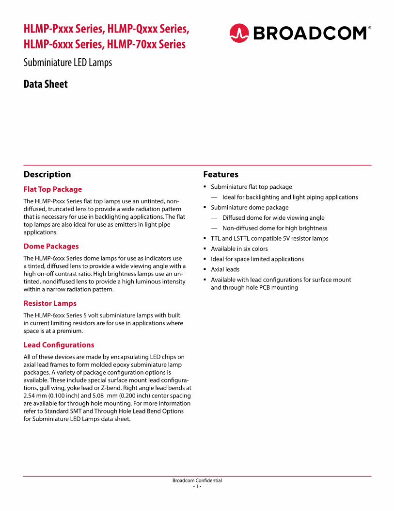
Device Selection Guide
Part Number: HLMP-xxxx
Standard Red
DH AS AlGaAs Red
High Efficiency
RedOrange Yellow High Perf.
GreenEmerald
GreenDevice
Description
Device Outline
Drawing
P005 P105 P205 P405 P305 P505 P605 Untinted, Non-diffused, Flat Top A
P102 P202 P402 P302 P502 Untinted, Diffused, Flat Top A
6000 Q100 6300 Q400 6400 6500 Q600 Tinted, Diffused B
Q105 6305 Q405 6405 6505 Q605 Untinted, Nondiffused, High Brightness B
Q150 7000 7019 7040 Tinted, Diffused, Low Current B
Q155 Nondiffused, Low Current B
6600 6800 Tinted, Diffused, Resistor, 5V, 10 mA B
6620 6720 6820 Diffused, Resistor, 5V, 4 mA B
0.50 (0.020) REF.
0.941.24
(0.037)(0.049)
2.92 (0.115)MAX.
0.760.89
(0.030)(0.035)
R.
0.630.38
(0.025)(0.015)
2.03 (0.080)1.78 (0.070)
0.79 (0.031)0.53 (0.021)
0.460.56
(0.018)(0.022)
0.25 (0.010) MAX.NOTE 2 0.20 (0.008) MAX.
CATHODE
1.651.91
(0.065)(0.075) DIA.
ANODE
11.6810.67
(0.460)(0.420)
BOTH SIDES
0.180.23
(0.007)(0.009)
2.082.34
(0.082)(0.092)
CATHODESTRIPE
2.211.96
(0.087)(0.077)
Diffused and Nondiffused
Package Dimensions Flat Top Lamps
NOTES:1. ALL DIMENSIONS ARE IN MILLIMETRES (INCHES).2. PROTRUDING SUPPORT TAB IS CONNECTED TO CATHODE LEAD.3. LEAD POLARITY FOR AlGaAs LAMPS IS OPPOSITE TO THE LEAD POLARITY OF SUBMINIATURE LAMPS USING OTHER TECHNOLOGIES.
0.460.56
(0.018)(0.022)
1.401.65
(0.055)(0.065)
0.25 (0.010) MAX.NOTE 2 0.20 (0.008) MAX.
0.50 (0.020) REF.
CATHODE
1.651.91
(0.065)(0.075) DIA.
ANODE
11.6810.67
(0.460)(0.420)
BOTH SIDES
1.141.40
(0.045)(0.055) 0.63
0.38(0.025)(0.015)
2.211.96
(0.087)(0.077)
0.180.23
(0.007)(0.009)
0.79 (0.031) MAX.
2.441.88
(0.096)(0.074)
2.082.34
(0.082)(0.092)
CATHODESTRIPE
Broadcom Confidential- 3 -
HLMP-Pxxx Series, HLMP-Qxxx Series, HLMP-6xxx Series, HLMP-70xx Series Data Sheet
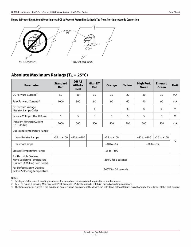
Notes:1. See Figure 5 for current derating vs. ambient temperature. Derating is not applicable to resistor lamps.2. Refer to Figure 6 showing Max. Tolerable Peak Current vs. Pulse Duration to establish pulsed operating conditions.3. The transient peak current is the maximum non-recurring peak current the device can withstand without failure. Do not operate these lamps at this high current.
Absolute Maximum Ratings (TA = 25°C)
Parameter Standard Red
DH AS AlGaAs
Red
High Eff. Red Orange Yellow High Perf.
GreenEmerald
Green Unit
DC Forward Current[1] 50 30 30 30 20 30 30 mA
Peak Forward Current[2] 1000 300 90 90 60 90 90 mA
DC Forward Voltage (Resistor Lamps Only) 6 6 6 6 V
Reverse Voltage (IR = 100 µA) 5 5 5 5 5 5 5 V
Transient Forward Current (10 µs Pulse) 2000 500 500 500 500 500 500 mA
Operating Temperature Range
°C Non-Resistor Lamps –55 to +100 –40 to +100 –55 to +100 –40 to +100 –20 to +100
Resistor Lamps –40 to +85 –20 to +85
Storage Temperature Range –55 to +100
For Thru Hole Devices: Wave Soldering Temperature [1.6 mm (0.063 in.) from body]
260°C for 5 seconds
For Surface Mount Devices: Reflow Soldering Temperature 260°C for 20 seconds
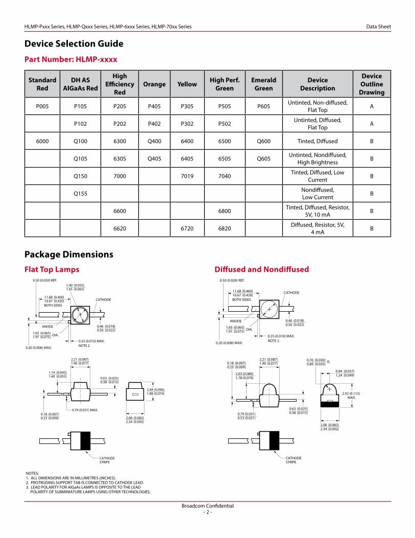
Figure 1: Proper Right Angle Mounting to a PCB to Prevent Protruding Cathode Tab from Shorting to Anode Connection
HLMP-PXXX Anode/Cathode
NO. ANODE DOWN. YES. CATHODE DOWN.
CATHODETAB
Broadcom Confidential- 4 -
HLMP-Pxxx Series, HLMP-Qxxx Series, HLMP-6xxx Series, HLMP-70xx Series Data Sheet
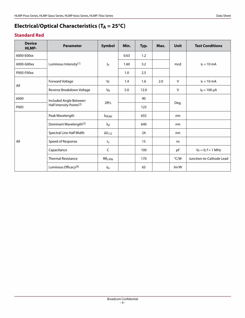
Electrical/Optical Characteristics (TA = 25°C)
Standard Red
Device HLMP- Parameter Symbol Min. Typ. Max. Unit Test Conditions
6000-E00xx
Luminous Intensity[1] IV
0.63 1.2
mcd IF = 10 mA6000-G00xx 1.60 3.2
P005-F00xx 1.0 2.5
AllForward Voltage VF 1.4 1.6 2.0 V IF = 10 mA
Reverse Breakdown Voltage VR 5.0 12.0 V IR = 100 µA
6000 Included Angle BetweenHalf Intensity Points[2] 2θ½
90Deg.
P005 125
All
Peak Wavelength λPEAK 655 nm
Dominant Wavelength[3] λd 640 nm
Spectral Line Half Width Δλ1/2 24 nm
Speed of Response τs 15 ns
Capacitance C 100 pF VF = 0; f = 1 MHz
Thermal Resistance RθJ-PIN 170 °C/W Junction-to-Cathode Lead
Luminous Efficacy[4] ηv 65 lm/W
Broadcom Confidential- 5 -
HLMP-Pxxx Series, HLMP-Qxxx Series, HLMP-6xxx Series, HLMP-70xx Series Data Sheet
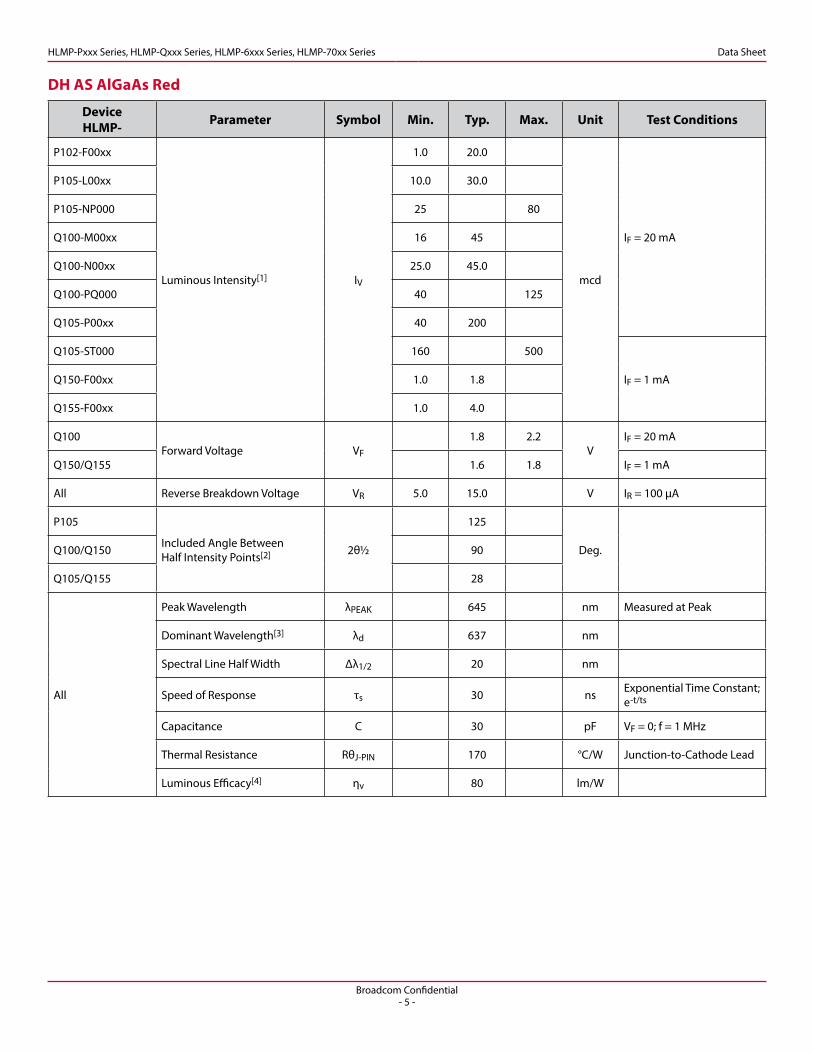
DH AS AlGaAs Red
Device HLMP- Parameter Symbol Min. Typ. Max. Unit Test Conditions
P102-F00xx
Luminous Intensity[1] IV
1.0 20.0
mcd
IF = 20 mA
P105-L00xx 10.0 30.0
P105-NP000 25 80
Q100-M00xx 16 45
Q100-N00xx 25.0 45.0
Q100-PQ000 40 125
Q105-P00xx 40 200
Q105-ST000 160 500
IF = 1 mAQ150-F00xx 1.0 1.8
Q155-F00xx 1.0 4.0
Q100Forward Voltage VF
1.8 2.2V
IF = 20 mA
Q150/Q155 1.6 1.8 IF = 1 mA
All Reverse Breakdown Voltage VR 5.0 15.0 V IR = 100 µA
P105
Included Angle BetweenHalf Intensity Points[2] 2θ½
125
Deg.Q100/Q150 90
Q105/Q155 28
All
Peak Wavelength λPEAK 645 nm Measured at Peak
Dominant Wavelength[3] λd 637 nm
Spectral Line Half Width Δλ1/2 20 nm
Speed of Response τs 30 ns Exponential Time Constant; e-t/ts
Capacitance C 30 pF VF = 0; f = 1 MHz
Thermal Resistance RθJ-PIN 170 °C/W Junction-to-Cathode Lead
Luminous Efficacy[4] ηv 80 lm/W
Broadcom Confidential- 6 -
HLMP-Pxxx Series, HLMP-Qxxx Series, HLMP-6xxx Series, HLMP-70xx Series Data Sheet
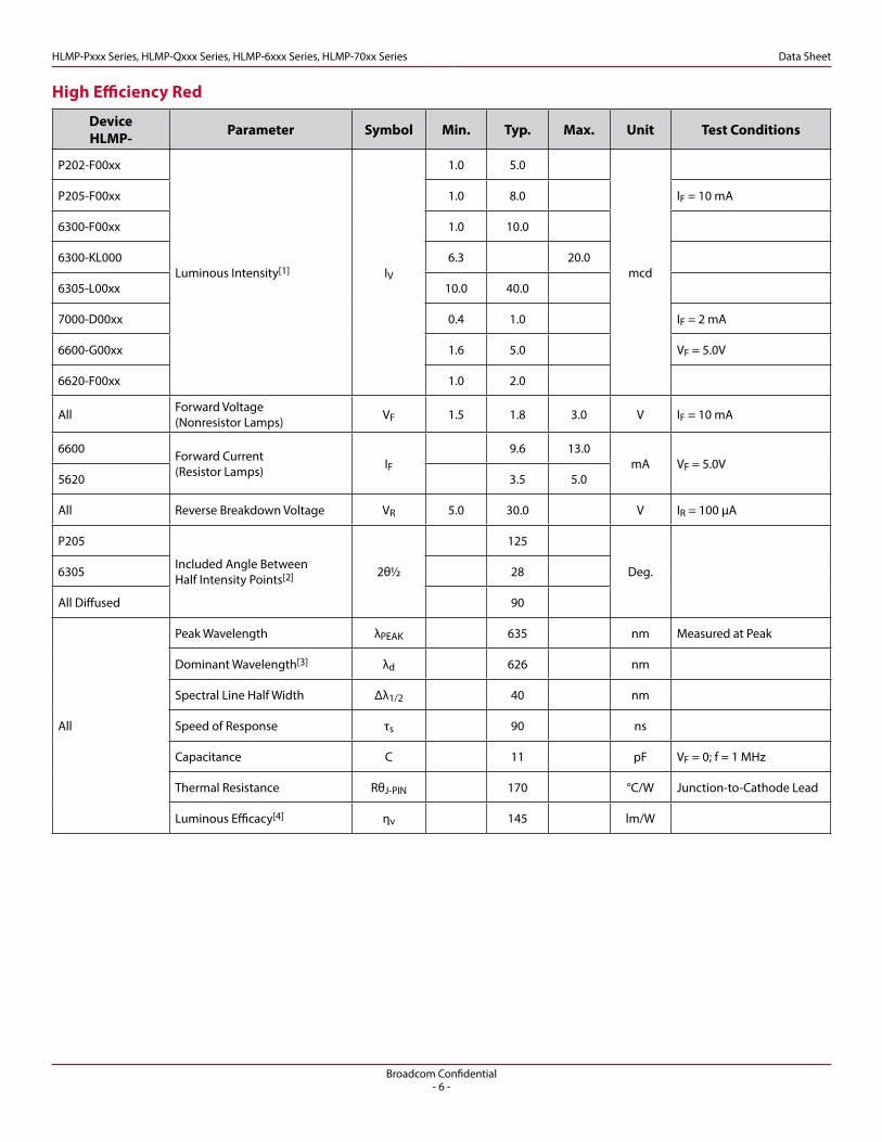
High Efficiency Red
Device HLMP- Parameter Symbol Min. Typ. Max. Unit Test Conditions
P202-F00xx
Luminous Intensity[1] IV
1.0 5.0
mcd
P205-F00xx 1.0 8.0 IF = 10 mA
6300-F00xx 1.0 10.0
6300-KL000 6.3 20.0
6305-L00xx 10.0 40.0
7000-D00xx 0.4 1.0 IF = 2 mA
6600-G00xx 1.6 5.0 VF = 5.0V
6620-F00xx 1.0 2.0
All Forward Voltage (Nonresistor Lamps) VF 1.5 1.8 3.0 V IF = 10 mA
6600 Forward Current (Resistor Lamps) IF
9.6 13.0mA VF = 5.0V
5620 3.5 5.0
All Reverse Breakdown Voltage VR 5.0 30.0 V IR = 100 µA
P205
Included Angle BetweenHalf Intensity Points[2] 2θ½
125
Deg.6305 28
All Diffused 90
All
Peak Wavelength λPEAK 635 nm Measured at Peak
Dominant Wavelength[3] λd 626 nm
Spectral Line Half Width Δλ1/2 40 nm
Speed of Response τs 90 ns
Capacitance C 11 pF VF = 0; f = 1 MHz
Thermal Resistance RθJ-PIN 170 °C/W Junction-to-Cathode Lead
Luminous Efficacy[4] ηv 145 lm/W
Broadcom Confidential- 7 -
HLMP-Pxxx Series, HLMP-Qxxx Series, HLMP-6xxx Series, HLMP-70xx Series Data Sheet
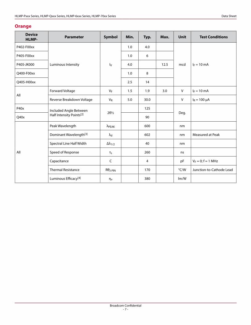
Orange
Device HLMP- Parameter Symbol Min. Typ. Max. Unit Test Conditions
P402-F00xx
Luminous Intensity IV
1.0 4.0
mcd IF = 10 mA
P405-F00xx 1.0 6
P405-JK000 4.0 12.5
Q400-F00xx 1.0 8
Q405-H00xx 2.5 14
AllForward Voltage VF 1.5 1.9 3.0 V IF = 10 mA
Reverse Breakdown Voltage VR 5.0 30.0 V IR = 100 µA
P40x Included Angle BetweenHalf Intensity Points[2] 2θ½
125Deg.
Q40x 90
All
Peak Wavelength λPEAK 600 nm
Dominant Wavelength[3] λd 602 nm Measured at Peak
Spectral Line Half Width Δλ1/2 40 nm
Speed of Response τs 260 ns
Capacitance C 4 pF VF = 0; f = 1 MHz
Thermal Resistance RθJ-PIN 170 °C/W Junction-to-Cathode Lead
Luminous Efficacy[4] ηv 380 lm/W
Broadcom Confidential- 8 -
HLMP-Pxxx Series, HLMP-Qxxx Series, HLMP-6xxx Series, HLMP-70xx Series Data Sheet
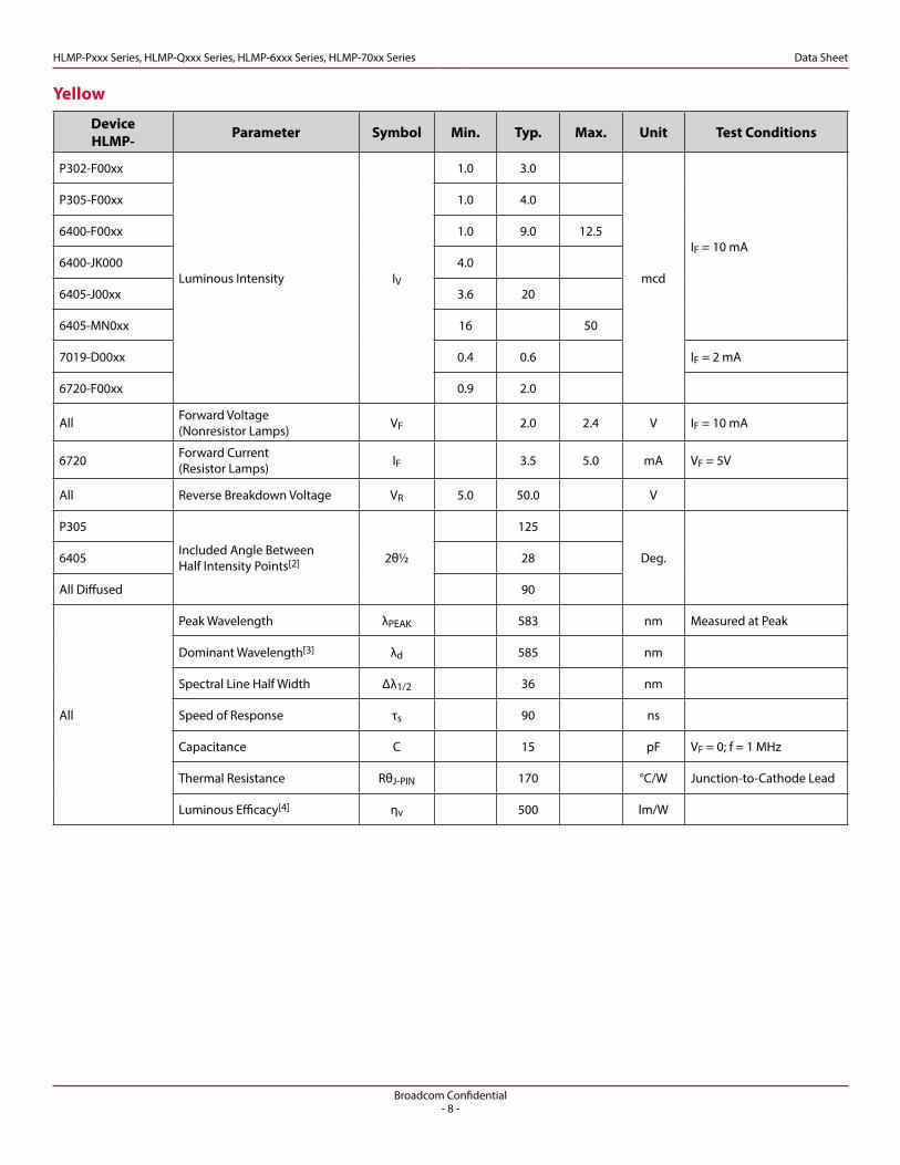
Yellow
Device HLMP- Parameter Symbol Min. Typ. Max. Unit Test Conditions
P302-F00xx
Luminous Intensity IV
1.0 3.0
mcd
IF = 10 mA
P305-F00xx 1.0 4.0
6400-F00xx 1.0 9.0 12.5
6400-JK000 4.0
6405-J00xx 3.6 20
6405-MN0xx 16 50
7019-D00xx 0.4 0.6 IF = 2 mA
6720-F00xx 0.9 2.0
All Forward Voltage (Nonresistor Lamps) VF 2.0 2.4 V IF = 10 mA
6720 Forward Current (Resistor Lamps) IF 3.5 5.0 mA VF = 5V
All Reverse Breakdown Voltage VR 5.0 50.0 V
P305
Included Angle BetweenHalf Intensity Points[2] 2θ½
125
Deg.6405 28
All Diffused 90
All
Peak Wavelength λPEAK 583 nm Measured at Peak
Dominant Wavelength[3] λd 585 nm
Spectral Line Half Width Δλ1/2 36 nm
Speed of Response τs 90 ns
Capacitance C 15 pF VF = 0; f = 1 MHz
Thermal Resistance RθJ-PIN 170 °C/W Junction-to-Cathode Lead
Luminous Efficacy[4] ηv 500 lm/W
Broadcom Confidential- 9 -
HLMP-Pxxx Series, HLMP-Qxxx Series, HLMP-6xxx Series, HLMP-70xx Series Data Sheet
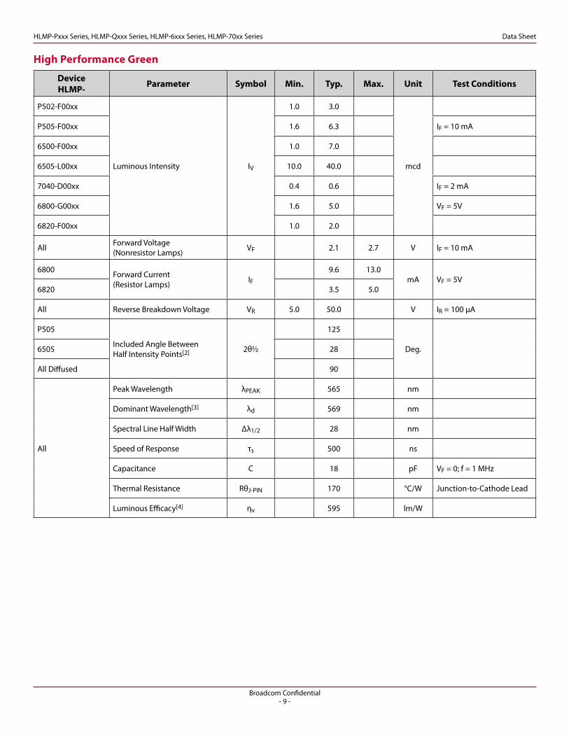
High Performance Green
Device HLMP- Parameter Symbol Min. Typ. Max. Unit Test Conditions
P502-F00xx
Luminous Intensity IV
1.0 3.0
mcd
P505-F00xx 1.6 6.3 IF = 10 mA
6500-F00xx 1.0 7.0
6505-L00xx 10.0 40.0
7040-D00xx 0.4 0.6 IF = 2 mA
6800-G00xx 1.6 5.0 VF = 5V
6820-F00xx 1.0 2.0
All Forward Voltage (Nonresistor Lamps) VF 2.1 2.7 V IF = 10 mA
6800 Forward Current (Resistor Lamps) IF
9.6 13.0mA VF = 5V
6820 3.5 5.0
All Reverse Breakdown Voltage VR 5.0 50.0 V IR = 100 µA
P505
Included Angle BetweenHalf Intensity Points[2] 2θ½
125
Deg.6505 28
All Diffused 90
All
Peak Wavelength λPEAK 565 nm
Dominant Wavelength[3] λd 569 nm
Spectral Line Half Width Δλ1/2 28 nm
Speed of Response τs 500 ns
Capacitance C 18 pF VF = 0; f = 1 MHz
Thermal Resistance RθJ-PIN 170 °C/W Junction-to-Cathode Lead
Luminous Efficacy[4] ηv 595 lm/W

Broadcom Confidential- 10 -
HLMP-Pxxx Series, HLMP-Qxxx Series, HLMP-6xxx Series, HLMP-70xx Series Data Sheet
Note:1. Please refer to Application Note 1061 for information comparing standard green and emerald green light output degradation.
High Performance Green[1]
Device HLMP- Parameter Symbol Min. Typ. Max. Unit Test Conditions
P605-F00xx
Luminous Intensity IV
1.0 1.5
mcd IF = 10 mAQ600-F00xx 1.0 1.5
Q605-F00xx 1.0 7.5
AllForward Voltage VF 2.2 3.0 V IF = 10 mA
Reverse Breakdown Voltage VR 5.0 V IR = 100 µA
P605 Included Angle BetweenHalf Intensity Points[2] 2θ½
125Deg.
Q60x 90
All
Peak Wavelength λPEAK 558 nm
Dominant Wavelength[3] λd 560 nm Measued at Peak
Spectral Line Half Width Δλ1/2 24 nm
Speed of Response τs 3100 ns
Capacitance C 35 pF VF = 0; f = 1 MHz
Thermal Resistance RθJ-PIN 170 °C/W Junction-to-Cathode Lead
Luminous Efficacy[4] ηv 656 lm/W
Broadcom Confidential- 11 -
HLMP-Pxxx Series, HLMP-Qxxx Series, HLMP-6xxx Series, HLMP-70xx Series Data Sheet
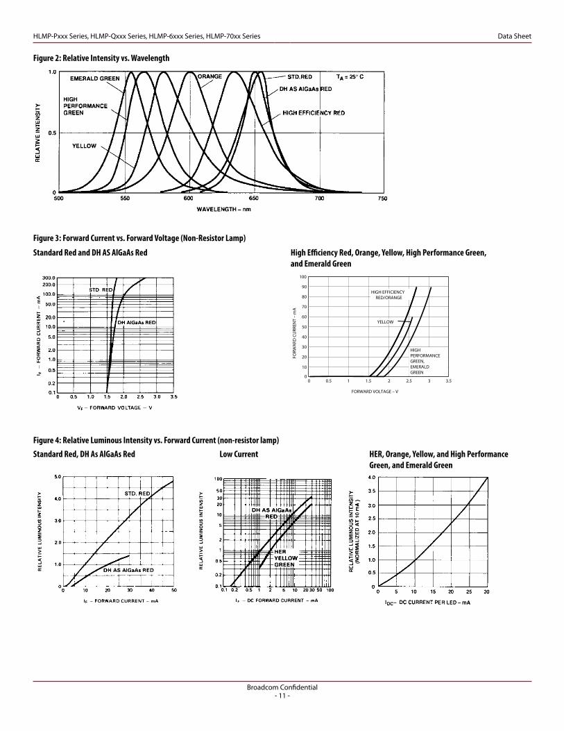
Standard Red, DH As AlGaAs Red
Standard Red and DH AS AlGaAs Red High Efficiency Red, Orange, Yellow, High Performance Green, and Emerald Green
HER, Orange, Yellow, and High Performance Green, and Emerald Green
Low Current
Figure 2: Relative Intensity vs. Wavelength
Figure 3: Forward Current vs. Forward Voltage (Non-Resistor Lamp)
Figure 4: Relative Luminous Intensity vs. Forward Current (non-resistor lamp)
HLMP-PXXX fig 2b
FORW
ARD
CU
RREN
T –
mA
100
0
FORWARD VOLTAGE – V
80
60
50
70
20
0
10
30
40
0.5 1 1.5 2 2.5 3 3.5
90
HIGHPERFORMANCEGREEN,EMERALDGREEN
YELLOW
HIGH EFFICIENCYRED/ORANGE
Broadcom Confidential- 12 -
HLMP-Pxxx Series, HLMP-Qxxx Series, HLMP-6xxx Series, HLMP-70xx Series Data Sheet
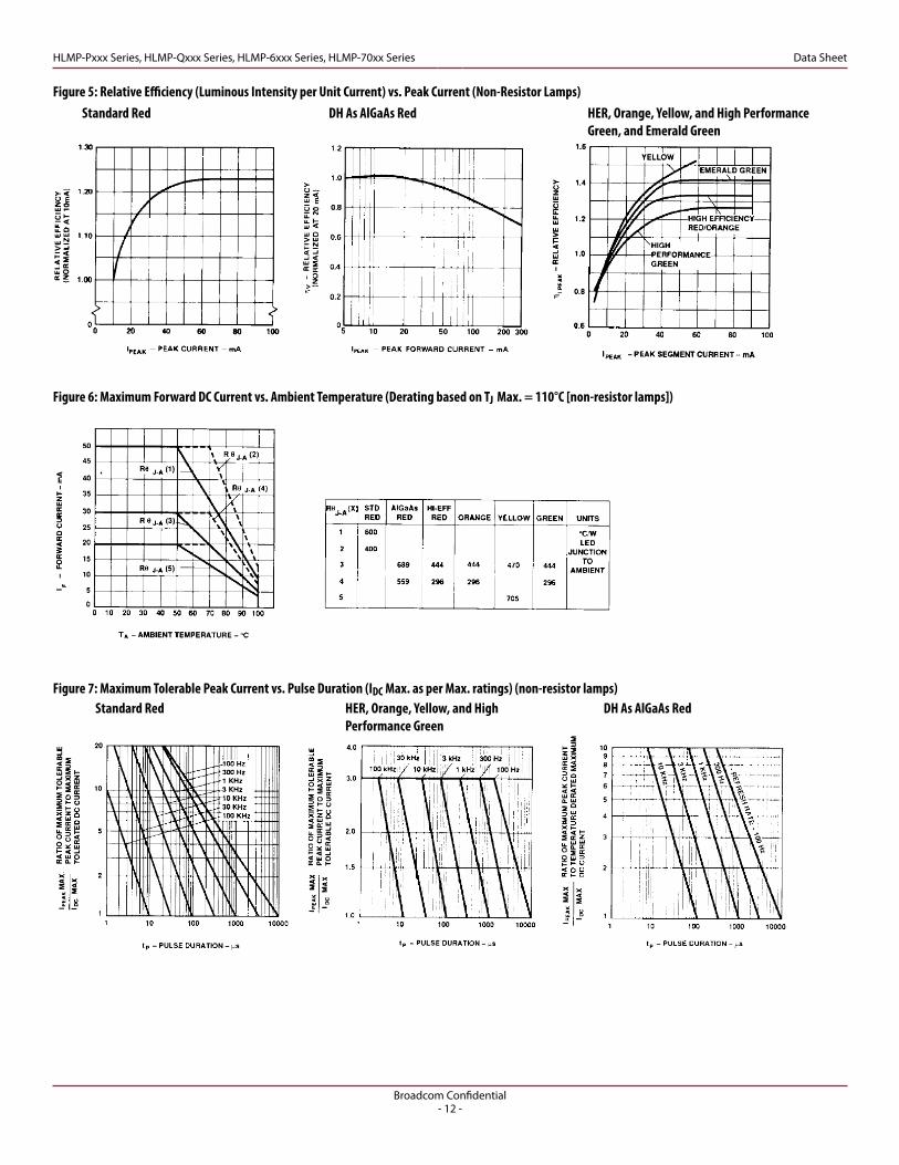
Figure 5: Relative Efficiency (Luminous Intensity per Unit Current) vs. Peak Current (Non-Resistor Lamps)
Figure 6: Maximum Forward DC Current vs. Ambient Temperature (Derating based on TJ Max. = 110°C [non-resistor lamps])
Figure 7: Maximum Tolerable Peak Current vs. Pulse Duration (IDC Max. as per Max. ratings) (non-resistor lamps)Standard Red
DH As AlGaAs RedStandard Red
HER, Orange, Yellow, and High Performance Green
DH As AlGaAs Red
HER, Orange, Yellow, and High Performance Green, and Emerald Green

Broadcom Confidential- 13 -
HLMP-Pxxx Series, HLMP-Qxxx Series, HLMP-6xxx Series, HLMP-70xx Series Data Sheet
Figure 10: Relative Intensity vs. Angular Displacement
Figure 8: Resistor Lamp Forward Current vs. Forward Voltage Figure 9: Resistor Lamp Luminous Intensity vs. Forward Voltage
Broadcom Confidential- 14 -
HLMP-Pxxx Series, HLMP-Qxxx Series, HLMP-6xxx Series, HLMP-70xx Series Data Sheet
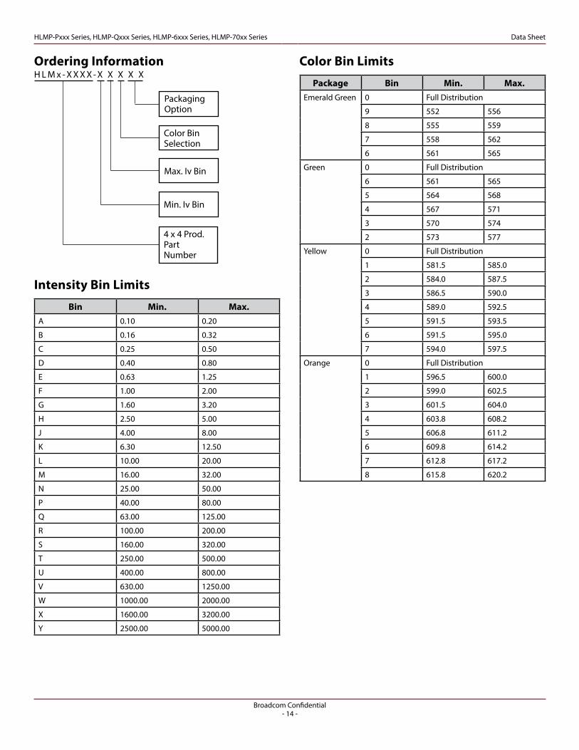
Ordering InformationH L M x - X X X X - X X X X X
4 x 4 Prod.PartNumber
Min. Iv Bin
Max. Iv Bin
Color Bin Selection
Packaging Option
Intensity Bin Limits
Bin Min. Max.A 0.10 0.20
B 0.16 0.32
C 0.25 0.50
D 0.40 0.80
E 0.63 1.25
F 1.00 2.00
G 1.60 3.20
H 2.50 5.00
J 4.00 8.00
K 6.30 12.50
L 10.00 20.00
M 16.00 32.00
N 25.00 50.00
P 40.00 80.00
Q 63.00 125.00
R 100.00 200.00
S 160.00 320.00
T 250.00 500.00
U 400.00 800.00
V 630.00 1250.00
W 1000.00 2000.00
X 1600.00 3200.00
Y 2500.00 5000.00
Color Bin Limits
Package Bin Min. Max.Emerald Green 0 Full Distribution
9 552 556
8 555 559
7 558 562
6 561 565
Green 0 Full Distribution
6 561 565
5 564 568
4 567 571
3 570 574
2 573 577
Yellow 0 Full Distribution
1 581.5 585.0
2 584.0 587.5
3 586.5 590.0
4 589.0 592.5
5 591.5 593.5
6 591.5 595.0
7 594.0 597.5
Orange 0 Full Distribution
1 596.5 600.0
2 599.0 602.5
3 601.5 604.0
4 603.8 608.2
5 606.8 611.2
6 609.8 614.2
7 612.8 617.2
8 615.8 620.2

Broadcom Confidential- 15 -
HLMP-Pxxx Series, HLMP-Qxxx Series, HLMP-6xxx Series, HLMP-70xx Series Data Sheet
Mechanical Option
00 Straight Leads, Bulk Packaging, Quantity of 500 Parts10 Right Angle Housing, Bulk Packaging, Quantity of 500 Parts
11 Gull Wing Leads, 12 mm Tape on 7 in. Dia. Reel, 1500 Parts per Reel
12 Gull Wing Lead, Bulk Packaging, Quantity of 500 Parts
14 Gull Wing Leads, 12 mm Tape on 13 in. Dia. Reel, 6000 Parts per Reel
21 Yoke Leads, 12 mm Tape on 7 in. Dia. Reel, 1500 Parts per Reel
22 Yoke Leads, Bulk Packaging, Quantity of 500 Parts
24 Yoke Leads, 12 mm Tape on 13 in. Dia. Reel, 6000 Parts per Reel
31 Z-Bend Leads, 12 mm Tape on 7 in. Dia. Reel, 1500 Parts per Reel
32 Z-Bend Leads, Bulk Packaging, Quantity of 500 Parts
34 Z-Bend Leads, 12 mm Tape on 13 in. Dia. Reel, 6000 Parts per Reel
1L 2.54 mm (0.100 inch) Center Lead Spacing, Long Leads; 10.4 mm (0.410 in.)
1S 2.54 mm (0.100 inch) Center Lead Spacing, Short Leads; 3.7 mm (0.145 in.)
2L 5.08 mm (0.200 inch) Center Lead Spacing, Long Leads; 10.4 mm (0.410 in.)
2S 5.08 mm (0.200 inch) Center Lead Spacing, Short Leads; 3.7 mm (0.145 in.)Note: All Categories are established for classification of products. Products may not be available in all categories. Please contact your local Avago representative for further clarification/information.

For product information and a complete list of distributors, please go to our web site: www.broadcom.com.
Broadcom, the pulse logo, Connecting everything, Avago Technologies, Avago, the A logo, and R2Coupler are among the trademarks of Broadcom and/or its affiliates in the United States, certain other countries and/or the EU.
Broadcom Proprietary and Confidential. Copyright © 2017 Broadcom. All Rights Reserved. The term “Broadcom” refers to Broadcom Limited and/or its subsidiaries.
Broadcom reserves the right to make changes without further notice to any products or data herein to improve reliability, function, or design. Information furnished by Broadcom is believed to be accurate and reliable. However, Broadcom does not assume any liability arising out of the application or use of this information, nor the application or use of any product or circuit described herein, neither does it convey any license under its patent rights nor the rights of others.AV02-3609EN – April 12, 2017
Related Documents