APPLIED ENGINEERING PRODUCTS 104 John W. Murphy Drive • P.O. Box 510 • New Haven, CT 06513 (203) 776-2813 • FAX (203) 776-8294 www.aepconnectors.com • e-mail: [email protected] SLB Series Subminiature RF Connectors Slide-on mating Frequency range DC-4 GHz Float mount / blind-mate versions ONLINE CATALOG SMB and SMC connectors also shown for comparison

Welcome message from author
This document is posted to help you gain knowledge. Please leave a comment to let me know what you think about it! Share it to your friends and learn new things together.
Transcript
APPLIED ENGINEERING PRODUCTS104 John W. Murphy Drive • P.O. Box 510 • New Haven, CT 06513
(203) 776-2813 • FAX (203) 776-8294
www.aepconnectors.com • e-mail: [email protected]
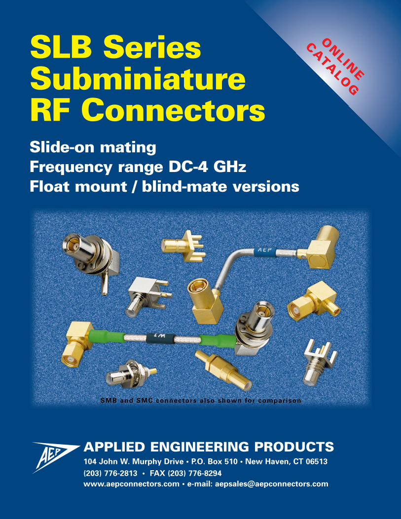
SLB SeriesSubminiatureRF ConnectorsSlide-on matingFrequency range DC-4 GHzFloat mount / blind-mate versions
ONLIN
E
CATA
LOG
SMB and SMC connectors also shown for comparison
SLB Subminiature ConnectorsClick on any line below to go directly to the appropriate page
APPLIED ENGINEERING PRODUCTS104 John W. Murphy Drive • P.O. Box 510 • New Haven, CT 06513
(203) 776-2813 • FAX (203) 776-8294www.aepconnectors.com • e-mail: [email protected]
Contents
Technical Information
Interfaces and specifications . . . . . . . . . . . 2Cable attachment methods. . . . . . . . . . . . . 3
Cable Connectors
Straight plugs for flexible and semi-rigid cable . . . . . . . . . . . . . . . . . . 4Right angle plugs for flexible and semi-rigid cable . . . . . . . . . . . . . . . . . . 4Bulkhead mounted plugs for flexible and semi-rigid cable . . . . . . . . . . . . . . . . . . 5Straight jacks for flexible and semi-rigid cable . . . . . . . . . . . . . . . . . . 6Right angle jacks for flexible and semi-rigid cable . . . . . . . . . . . . . . . . . . 6Straight bulkhead jacks for flexible and semi-rigid cable . . . . . . . . . . . . . . . . . . 7Right angle bulkhead jacks for flexible and semi-rigid cable . . . . . . . . . . . . . . . . . . 7
Receptacles
Straight and right angle bulkhead jack receptacles . . . . . . . . . . . . . . 8Straight and right angle bulkhead plug receptacles . . . . . . . . . . . . . 9Straight P.C. board jacks . . . . . . . . . . . . . . 10
Straight bulkhead mounted P.C. board jacks . . . . . . . . . . . . . . . . . . . . . 10
Straight P.C. board plugs . . . . . . . . . . . . . 10
Right angle P.C. board jacks . . . . . . . . . . . 11
Right angle bulkhead mounted P.C. board jacks . . . . . . . . . . . . . . . . . . . . . 11
Right angle P.C. board plugs. . . . . . . . . . . 11
Float Mount / Blind Mate Connectors
Introduction. . . . . . . . . . . . . . . . . . . . . . . . 12
Bulkhead mounted plugs for flexible and semi-rigid cable . . . . . . . . . . . . . . . . . 13
Straight bulkhead jacks for flexible and semi-rigid cable . . . . . . . . . . . . . . . . . 14
Right angle bulkhead jacks for flexible and semi-rigid cable . . . . . . . . . . . . . . . . . 15
Straight bulkhead jack receptacles . . . . . . . . . . . . . . . . . . . . . 16
Straight bulkhead plug receptacles . . . . . . . . . . . . . . . . . . . . 17
Straight and right angle bulkhead mounted P.C. board jacks . . . . . . . . . . . . . 18
Straight and right angle P.C. board plugs (closed-entry mating end hoods) . . . . . . . . . . . . . 19
Vibration-Proof Float Mount Plugs
Introduction. . . . . . . . . . . . . . . . . . . . . . . . 20
Straight plugs for flexible cable . . . . . . . . 21
Right angle plugs for flexible cable . . . . . 21
Adapters
Straight adapters within series. . . . . . . . . 22
Cable Assembly Instructions
Clamp type connectors for flexible cable . . . . . . . . . . . . . . . . . . . . . . . 23
Crimp type connectors for flexible cable . . . . . . . . . . . . . . . . . . . . . . . 24
Solder-clamp connectors for semi-rigid cable. . . . . . . . . . . . . . . . . . . . . 25
Assembly Tooling . . . . . . . . . . . . . . . . . . . 26
Mounting Dimensions . . . . . . . . . . . . . . . 26
Index by AEP Part Number . . . . . . . . . . . . 27
About AEP . . . . . . . . . . . . . . . . . . . . . . . . . 28
Other AEP Product Lines . . . . . . . . . . . . . 29
1
(203) 776-2813 • FAX (203) 776-8294APPLIED ENGINEERING PRODUCTS
www.aepconnectors.com • [email protected] 2
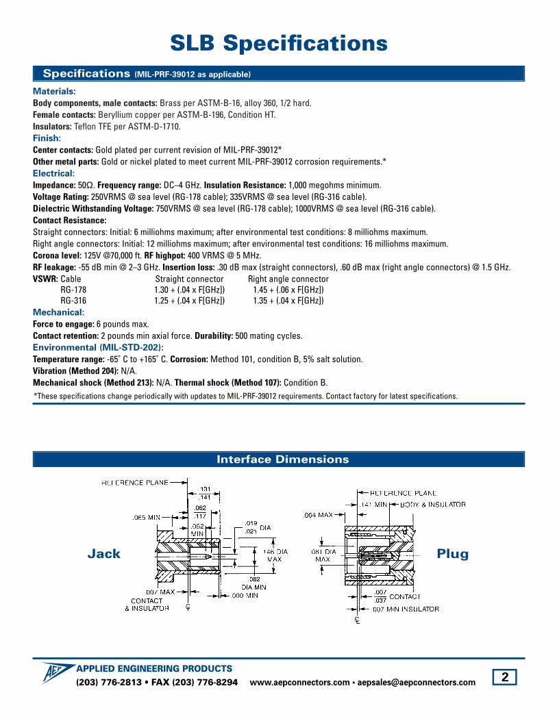
SLB Specifications
Interface Dimensions
Specifications (MIL-PRF-39012 as applicable)
Materials:
Body components, male contacts: Brass per ASTM-B-16, alloy 360, 1/2 hard. Female contacts: Beryllium copper per ASTM-B-196, Condition HT. Insulators: Teflon TFE per ASTM-D-1710. Finish:
Center contacts: Gold plated per current revision of MIL-PRF-39012*Other metal parts: Gold or nickel plated to meet current MIL-PRF-39012 corrosion requirements.*Electrical:
Impedance: 50Ω. Frequency range: DC–4 GHz. Insulation Resistance: 1,000 megohms minimum.Voltage Rating: 250VRMS @ sea level (RG-178 cable); 335VRMS @ sea level (RG-316 cable).Dielectric Withstanding Voltage: 750VRMS @ sea level (RG-178 cable); 1000VRMS @ sea level (RG-316 cable).Contact Resistance:Straight connectors: Initial: 6 milliohms maximum; after environmental test conditions: 8 milliohms maximum.Right angle connectors: Initial: 12 milliohms maximum; after environmental test conditions: 16 milliohms maximum.Corona level: 125V @70,000 ft. RF highpot: 400 VRMS @ 5 MHz.RF leakage: -55 dB min @ 2–3 GHz. Insertion loss: .30 dB max (straight connectors), .60 dB max (right angle connectors) @ 1.5 GHz.VSWR: Cable Straight connector Right angle connector
RG-178 1.30 + (.04 x F[GHz]) 1.45 + (.06 x F[GHz])RG-316 1.25 + (.04 x F[GHz]) 1.35 + (.04 x F[GHz])
Mechanical:
Force to engage: 6 pounds max.Contact retention: 2 pounds min axial force. Durability: 500 mating cycles.Environmental (MIL-STD-202):
Temperature range: -65˚ C to +165˚ C. Corrosion: Method 101, condition B, 5% salt solution.Vibration (Method 204): N/A.Mechanical shock (Method 213): N/A. Thermal shock (Method 107): Condition B.*These specifications change periodically with updates to MIL-PRF-39012 requirements. Contact factory for latest specifications.
PlugJack
(203) 776-2813 • FAX (203) 776-8294APPLIED ENGINEERING PRODUCTS
www.aepconnectors.com • [email protected] 3
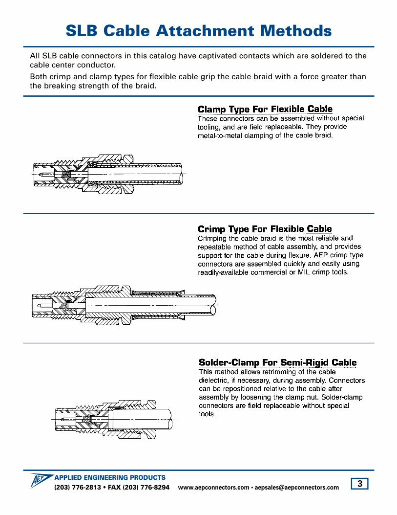
SLB Cable Attachment MethodsAll SLB cable connectors in this catalog have captivated contacts which are soldered to thecable center conductor.
Both crimp and clamp types for flexible cable grip the cable braid with a force greater thanthe breaking strength of the braid.

SLB Cable PlugsClick on part number to go directly to cable assembly instructions
Straight Plugs
Right Angle Plugs
(203) 776-2813 • FAX (203) 776-8294APPLIED ENGINEERING PRODUCTS
www.aepconnectors.com • [email protected] 4
Substitute the appropriate cable group number for “XX” when ordering:
GROUP CABLE TYPES
02 RG178, RG196, M17/93, M17/169
03RG174, RG179, RG316, M17/113, M17/119, M17/172, M17/189
GROUP CABLE TYPES
05 RG178DS, RG196DS
09 .141" semi-rigid, RG 402M17/130
GROUP CABLE TYPES
10 .085" semi-rigid, RG405, M17/133
19RG174DS, RG316DS, M17/151,M17/152, Times RD-316
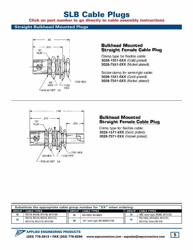
SLB Cable PlugsClick on part number to go directly to cable assembly instructions
Straight Bulkhead Mounted Plugs
(203) 776-2813 • FAX (203) 776-8294APPLIED ENGINEERING PRODUCTS
www.aepconnectors.com • [email protected] 5
Substitute the appropriate cable group number for “XX” when ordering:
GROUP CABLE TYPES
02 RG178, RG196, M17/93, M17/169
03RG174, RG179, RG316, M17/113, M17/119, M17/172, M17/189
GROUP CABLE TYPES
05 RG178DS, RG196DS
09 .141" semi-rigid, RG 402M17/130
GROUP CABLE TYPES
10 .085" semi-rigid, RG405, M17/133
19RG174DS, RG316DS, M17/151,M17/152, Times RD-316

(203) 776-2813 • FAX (203) 776-8294APPLIED ENGINEERING PRODUCTS
www.aepconnectors.com • [email protected] 6
SLB Cable JacksClick on part number to go directly to cable assembly instructions
Straight Jacks
Right Angle Jacks
Substitute the appropriate cable group number for “XX” when ordering:
GROUP CABLE TYPES
02 RG178, RG196, M17/93, M17/169
03RG174, RG179, RG316, M17/113, M17/119, M17/172, M17/189
GROUP CABLE TYPES
05 RG178DS, RG196DS
09 .141" semi-rigid, RG 402M17/130
GROUP CABLE TYPES
10 .085" semi-rigid, RG405, M17/133
19RG174DS, RG316DS, M17/151,M17/152, Times RD-316

(203) 776-2813 • FAX (203) 776-8294APPLIED ENGINEERING PRODUCTS
www.aepconnectors.com • [email protected] 7
SLB Bulkhead Mounted Cable JacksClick on part number to go directly to cable assembly instructions
Straight Jacks
Right Angle Jacks
Substitute the appropriate cable group number for “XX” when ordering:
GROUP CABLE TYPES
02 RG178, RG196, M17/93, M17/169
03RG174, RG179, RG316, M17/113, M17/119, M17/172, M17/189
GROUP CABLE TYPES
05 RG178DS, RG196DS
09 .141" semi-rigid, RG 402M17/130
GROUP CABLE TYPES
10 .085" semi-rigid, RG405, M17/133
19RG174DS, RG316DS, M17/151,M17/152, Times RD-316
(203) 776-2813 • FAX (203) 776-8294APPLIED ENGINEERING PRODUCTS
www.aepconnectors.com • [email protected] 8
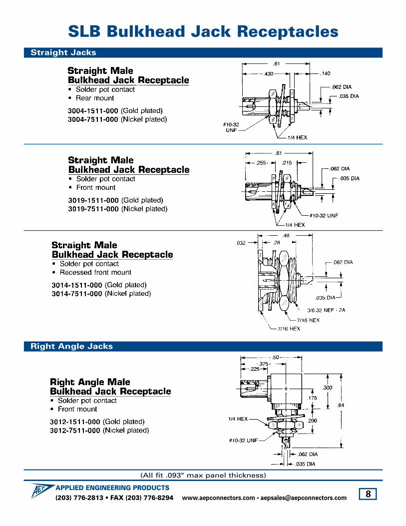
SLB Bulkhead Jack ReceptaclesStraight Jacks
Right Angle Jacks
(All fit .093" max panel thickness)
(203) 776-2813 • FAX (203) 776-8294APPLIED ENGINEERING PRODUCTS
www.aepconnectors.com • [email protected] 9
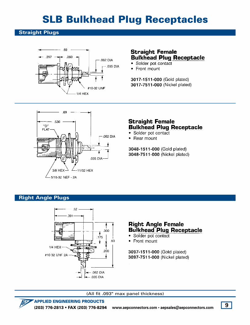
SLB Bulkhead Plug ReceptaclesStraight Plugs
Right Angle Plugs
(All fit .093" max panel thickness)
(203) 776-2813 • FAX (203) 776-8294APPLIED ENGINEERING PRODUCTS
www.aepconnectors.com • [email protected] 10
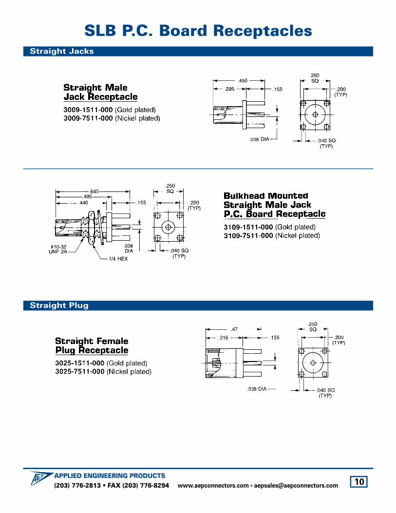
SLB P.C. Board ReceptaclesStraight Jacks
Straight Plug

(203) 776-2813 • FAX (203) 776-8294APPLIED ENGINEERING PRODUCTS
www.aepconnectors.com • [email protected] 11
SLB P.C. Board ReceptaclesRight Angle Jacks
Right Angle Plug
(203) 776-2813 • FAX (203) 776-8294APPLIED ENGINEERING PRODUCTS
www.aepconnectors.com • [email protected] 12
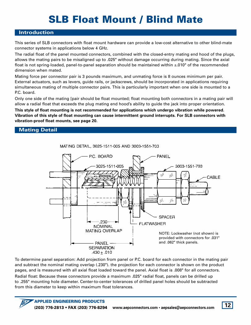
SLB Float Mount / Blind MateIntroduction
Mating Detail
This series of SLB connectors with float mount hardware can provide a low-cost alternative to other blind-mateconnector systems in applications below 4 GHz.
The radial float of the panel mounted connectors, combined with the closed-entry mating end hood of the plugs,allows the mating pairs to be misaligned up to .025" without damage occurring during mating. Since the axialfloat is not spring-loaded, panel-to-panel separation should be maintained within ±.010" of the recommendeddimension when mated.
Mating force per connector pair is 3 pounds maximum, and unmating force is 8 ounces minimum per pair.External actuators, such as levers, guide rails, or jackscrews, should be incorporated in applications requiringsimultaneous mating of multiple connector pairs. This is particularly important when one side is mounted to aP.C. board.
Only one side of the mating [pair should be float mounted; float mounting both connectors in a mating pair willallow a radial float that exceeds the plug mating end hood’s ability to guide the jack into proper orientation.
This style of float mounting is not recommended for applications which undergo vibration while powered.
Vibration of this style of float mounting can cause intermittent ground interrupts. For SLB connectors with
vibration-proof float mounts, see page 20.
To determine panel separation: Add projection from panel or P.C. board for each connector in the mating pairand subtract the nominal mating overlap (.230"). the projection for each connector is shown on the productpages, and is measured with all axial float loaded toward the panel. Axial float is .008" for all connectors.
Radial float: Because these connectors provide a maximum .025" radial float, panels can be drilled up to .255" mounting hole diameter. Center-to-center tolerances of drilled panel holes should be subtracted from this diameter to keep within maximum float tolerances.
NOTE: Lockwasher (not shown) isprovided with connectors for .031"and .062" thick panels.
(203) 776-2813 • FAX (203) 776-8294APPLIED ENGINEERING PRODUCTS
www.aepconnectors.com • [email protected] 13
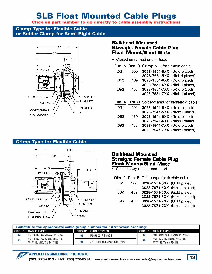
SLB Float Mounted Cable PlugsClick on part number to go directly to cable assembly instructions
Clamp Type for Flexible Cable
or Solder-Clamp for Semi-Rigid Cable
Crimp Type for Flexible Cable
Substitute the appropriate cable group number for “XX” when ordering:
GROUP CABLE TYPES
02 RG178, RG196, M17/93, M17/169
03RG174, RG179, RG316, M17/113, M17/119, M17/172, M17/189
GROUP CABLE TYPES
05 RG178DS, RG196DS
09 .141" semi-rigid, RG 402M17/130
GROUP CABLE TYPES
10 .085" semi-rigid, RG405, M17/133
19RG174DS, RG316DS, M17/151,M17/152, Times RD-316

(203) 776-2813 • FAX (203) 776-8294APPLIED ENGINEERING PRODUCTS
www.aepconnectors.com • [email protected] 14
SLB Float Mounted Bulkhead JacksClick on part number to go directly to cable assembly instructions
Clamp Type for Flexible Cable
or Solder-Clamp for Semi-Rigid Cable
Crimp Type for Flexible Cable
Substitute the appropriate cable group number for “XX” when ordering:
GROUP CABLE TYPES
02 RG178, RG196, M17/93, M17/169
03RG174, RG179, RG316, M17/113, M17/119, M17/172, M17/189
GROUP CABLE TYPES
05 RG178DS, RG196DS
09 .141" semi-rigid, RG 402M17/130
GROUP CABLE TYPES
10 .085" semi-rigid, RG405, M17/133
19RG174DS, RG316DS, M17/151,M17/152, Times RD-316

(203) 776-2813 • FAX (203) 776-8294APPLIED ENGINEERING PRODUCTS
www.aepconnectors.com • [email protected] 15
SLB Float Mounted Bulkhead JacksClick on part number to go directly to cable assembly instructions
Clamp Type for Flexible Cable
or Solder-Clamp for Semi-Rigid Cable
Crimp Type for Flexible Cable
Substitute the appropriate cable group number for “XX” when ordering:
GROUP CABLE TYPES
02 RG178, RG196, M17/93, M17/169
03RG174, RG179, RG316, M17/113, M17/119, M17/172, M17/189
GROUP CABLE TYPES
05 RG178DS, RG196DS
09 .141" semi-rigid, RG 402M17/130
GROUP CABLE TYPES
10 .085" semi-rigid, RG405, M17/133
19RG174DS, RG316DS, M17/151,M17/152, Times RD-316

(203) 776-2813 • FAX (203) 776-8294APPLIED ENGINEERING PRODUCTS
www.aepconnectors.com • [email protected] 16
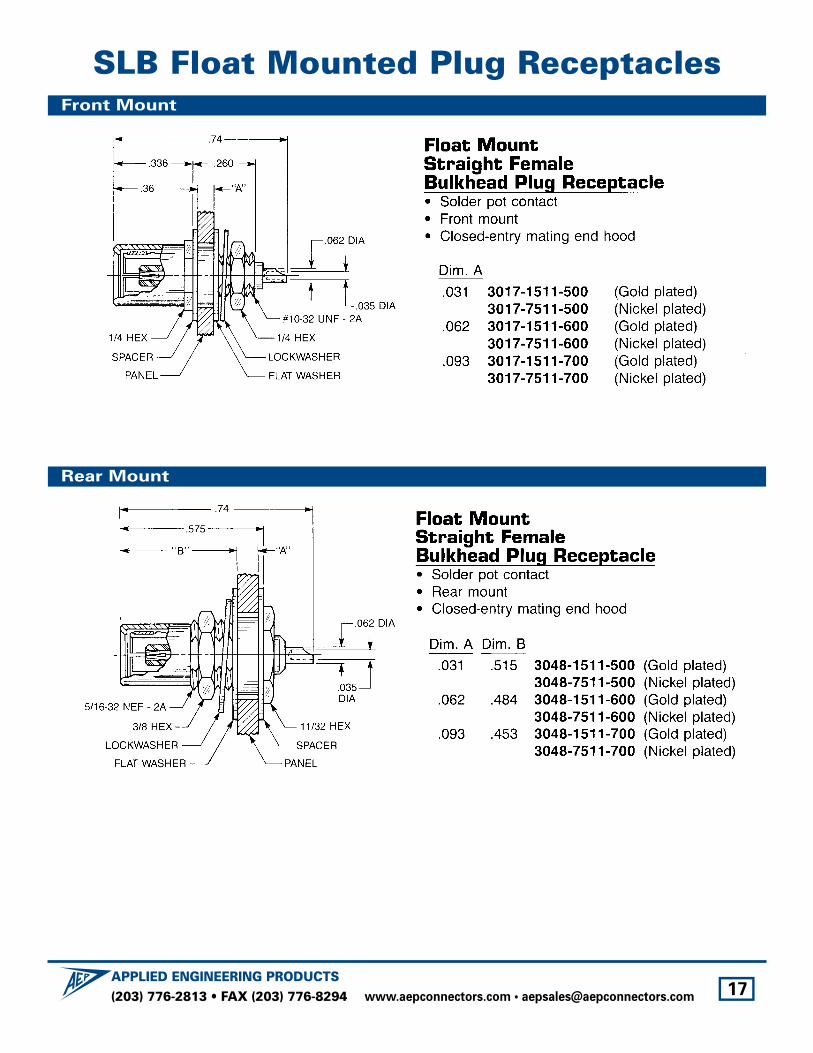
SLB Float Mounted Jack ReceptaclesRear Mount
Front Mount
Recessed Mount
(203) 776-2813 • FAX (203) 776-8294APPLIED ENGINEERING PRODUCTS
www.aepconnectors.com • [email protected] 17
SLB Float Mounted Plug ReceptaclesFront Mount
Rear Mount
(203) 776-2813 • FAX (203) 776-8294APPLIED ENGINEERING PRODUCTS
www.aepconnectors.com • [email protected] 18
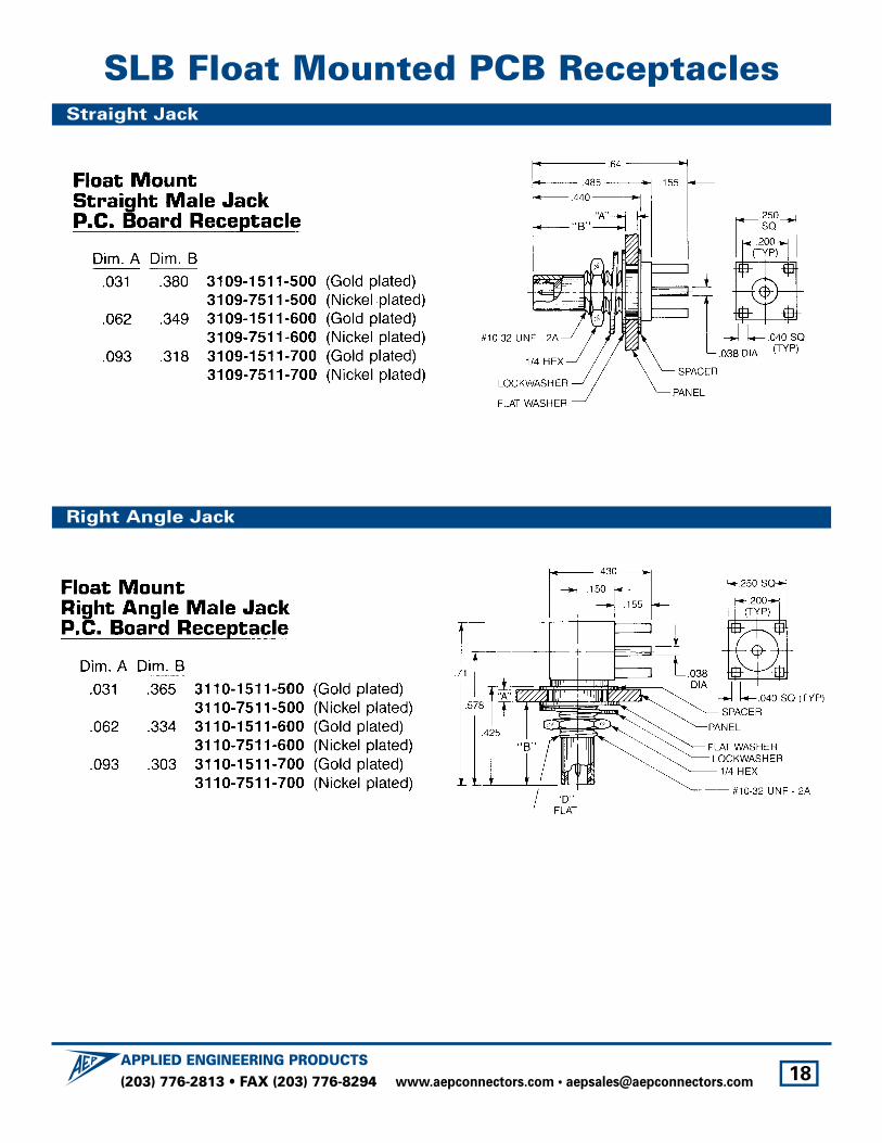
SLB Float Mounted PCB ReceptaclesStraight Jack
Right Angle Jack

(203) 776-2813 • FAX (203) 776-8294APPLIED ENGINEERING PRODUCTS
www.aepconnectors.com • [email protected] 19
SLB Closed-Entry PCB PlugsFor use with float-mounted jacks
Straight Plug
Right Angle Plug
(203) 776-2813 • FAX (203) 776-8294APPLIED ENGINEERING PRODUCTS
www.aepconnectors.com • [email protected] 20
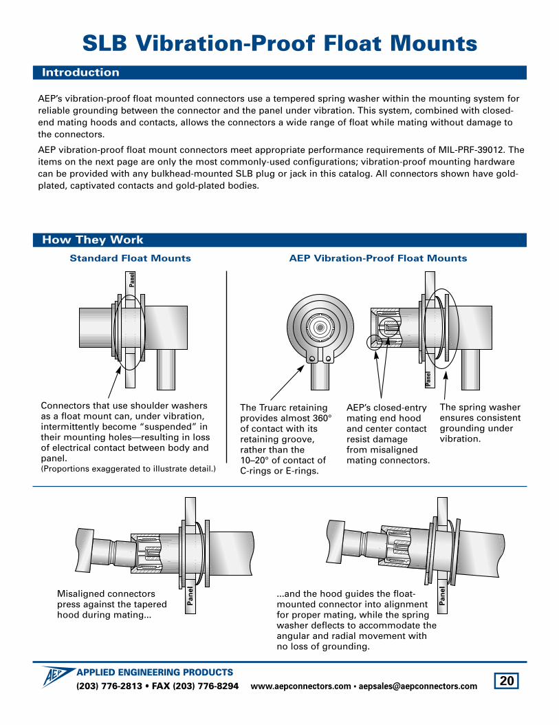
AEP’s vibration-proof float mounted connectors use a tempered spring washer within the mounting system forreliable grounding between the connector and the panel under vibration. This system, combined with closed-end mating hoods and contacts, allows the connectors a wide range of float while mating without damage tothe connectors.
AEP vibration-proof float mount connectors meet appropriate performance requirements of MIL-PRF-39012. Theitems on the next page are only the most commonly-used configurations; vibration-proof mounting hardwarecan be provided with any bulkhead-mounted SLB plug or jack in this catalog. All connectors shown have gold-plated, captivated contacts and gold-plated bodies.
The Truarc retainingprovides almost 360°of contact with itsretaining groove,rather than the10–20° of contact ofC-rings or E-rings.
AEP’s closed-entrymating end hoodand center contactresist damagefrom misalignedmating connectors.
The spring washerensures consistentgrounding undervibration.
Pane
l
Pane
l
Connectors that use shoulder washers as a float mount can, under vibration,intermittently become “suspended” intheir mounting holes—resulting in loss of electrical contact between body andpanel. (Proportions exaggerated to illustrate detail.)
Pan
el
Pan
el
Misaligned connectorspress against the taperedhood during mating...
...and the hood guides the float-mounted connector into alignment for proper mating, while the spring washer deflects to accommodate theangular and radial movement with no loss of grounding.
Standard Float Mounts AEP Vibration-Proof Float Mounts
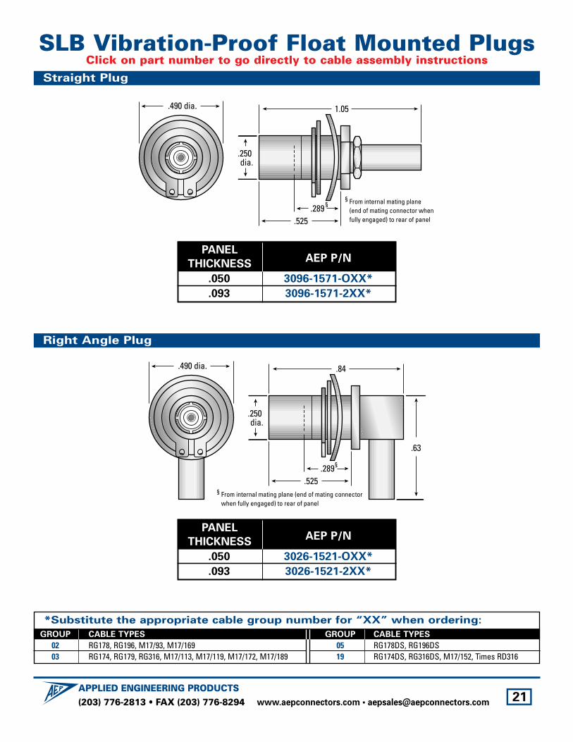
SLB Vibration-Proof Float MountsIntroduction
How They Work
(203) 776-2813 • FAX (203) 776-8294APPLIED ENGINEERING PRODUCTS
www.aepconnectors.com • [email protected] 21
*Substitute the appropriate cable group number for “XX” when ordering:
GROUP CABLE TYPES
02 RG178, RG196, M17/93, M17/16903 RG174, RG179, RG316, M17/113, M17/119, M17/172, M17/189
GROUP CABLE TYPES
05 RG178DS, RG196DS19 RG174DS, RG316DS, M17/152, Times RD316
PANEL
THICKNESSAEP P/N
.050 3096-1571-OXX*
.093 3096-1571-2XX*
.84
.63
.525.289
§ From internal mating plane (end of mating connector when fully engaged) to rear of panel
.490 dia.
.250 dia.
§
.525
1.05
.289
.490 dia.
.250 dia.
§ From internal mating plane (end of mating connector when fully engaged) to rear of panel
§
SLB Vibration-Proof Float Mounted PlugsClick on part number to go directly to cable assembly instructions
Straight Plug
Right Angle Plug
PANEL
THICKNESSAEP P/N
.050 3026-1521-OXX*
.093 3026-1521-2XX*

(203) 776-2813 • FAX (203) 776-8294APPLIED ENGINEERING PRODUCTS
www.aepconnectors.com • [email protected] 22
SLB AdaptersStraight Jack to jack, Bulkhead Mounted
Straight Jack to jack, Float Mounted
(203) 776-2813 • FAX (203) 776-8294APPLIED ENGINEERING PRODUCTS
www.aepconnectors.com • [email protected] 23
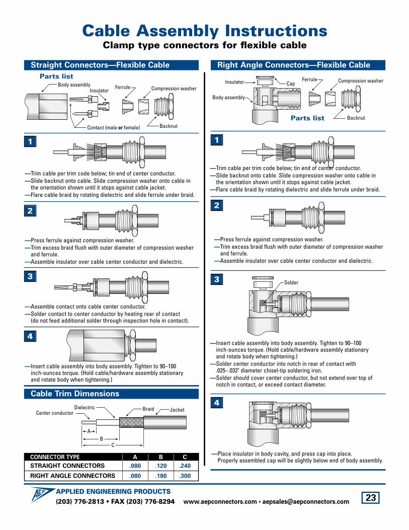
Body assemblyCompression washerFerrule
Insulator
Contact (male or female) Backnut
—Assemble contact onto cable center conductor.—Solder contact to center conductor by heating rear of contact
(do not feed additional solder through inspection hole in contact).
—Press ferrule against compression washer. —Trim excess braid flush with outer diameter of compression washer
and ferrule.—Assemble insulator over cable center conductor and dielectric.
Compression washerFerrule
Backnut
Body assembly
CapInsulator
Solder
Cable Assembly InstructionsClamp type connectors for flexible cable
Straight Connectors—Flexible Cable
Cable Trim Dimensions
Right Angle Connectors—Flexible Cable
Parts list
BC
A
Braid JacketCenter conductorDielectric
—Trim cable per trim code below; tin end of center conductor.—Slide backnut onto cable. Slide compression washer onto cable in
the orientation shown until it stops against cable jacket.—Flare cable braid by rotating dielectric and slide ferrule under braid.
1
2
3
—Insert cable assembly into body assembly. Tighten to 90–100 inch-ounces torque. (Hold cable/hardware assembly stationary and rotate body when tightening.)
4—Insert cable assembly into body assembly. Tighten to 90–100
inch-ounces torque. (Hold cable/hardware assembly stationary and rotate body when tightening.)
—Solder center conductor into notch in rear of contact with .025–.032" diameter chisel-tip soldering iron.
—Solder should cover center conductor, but not extend over top ofnotch in contact, or exceed contact diameter.
—Press ferrule against compression washer. —Trim excess braid flush with outer diameter of compression washer
and ferrule.—Assemble insulator over cable center conductor and dielectric.
—Trim cable per trim code below; tin end of center conductor.—Slide backnut onto cable. Slide compression washer onto cable in
the orientation shown until it stops against cable jacket.—Flare cable braid by rotating dielectric and slide ferrule under braid.
1
2
3
—Place insulator in body cavity, and press cap into place.Properly assembled cap will be slightly below end of body assembly.
4
Parts list
CONNECTOR TYPE A B C
STRAIGHT CONNECTORS .080 .120 .240
RIGHT ANGLE CONNECTORS .080 .180 .300
(203) 776-2813 • FAX (203) 776-8294APPLIED ENGINEERING PRODUCTS
www.aepconnectors.com • [email protected] 24
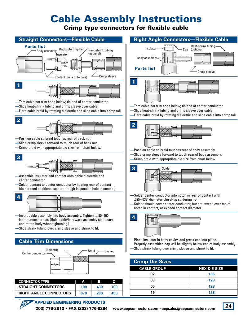
Body assembly Heat-shrink tubing(optional)
Backnut/crimp tail
Insulator
Contact (male or female) Crimp sleeve
—Assemble insulator and contact onto cable dielectric and center conductor.
—Solder contact to center conductor by heating rear of contact (do not feed additional solder through inspection hole in contact).
—Position cable so braid touches rear of back nut.—Slide crimp sleeve forward to touch rear of back nut.—Crimp braid with appropriate die size from chart below.
Body assembly
CapInsulatorHeat-shrink tubing(optional)
Crimp sleeve
Solder
Straight Connectors—Flexible Cable
Cable Trim Dimensions
Right Angle Connectors—Flexible Cable
Parts list
BC
A
Braid JacketCenter conductorDielectric
—Trim cable per trim code below; tin end of center conductor.—Slide heat-shrink tubing and crimp sleeve over cable.—Flare cable braid by rotating dielectric and slide cable into crimp tail.
1
2
3
—Insert cable assembly into body assembly. Tighten to 90–100 inch-ounces torque. (Hold cable/hardware assembly stationary and rotate body when tightening.)
—Slide shrink tubing over crimp sleeve and shrink to fit.
4 —Solder center conductor into notch in rear of contact with .025–.032" diameter chisel-tip soldering iron.
—Solder should cover center conductor, but not extend over top ofnotch in contact, or exceed contact diameter.
—Position cable so braid touches rear of body assembly.—Slide crimp sleeve forward to touch rear of body assembly.—Crimp braid with appropriate die size from chart below.
—Trim cable per trim code below; tin end of center conductor.—Slide heat-shrink tubing and crimp sleeve over cable.—Flare cable braid by rotating dielectric and slide cable into crimp tail.
1
2
3
—Place insulator in body cavity, and press cap into place.Properly assembled cap will be slightly below end of body assembly.
—Slide shrink tubing over crimp sleeve and shrink to fit.
4
Parts list
Crimp Die Sizes
CABLE GROUP HEX DIE SIZE
02 .105
03 .128
05 .128
19 .128
Cable Assembly InstructionsCrimp type connectors for flexible cable
CONNECTOR TYPE A B C
STRAIGHT CONNECTORS .100 .430 .700
RIGHT ANGLE CONNECTORS .070 .200 .450
(203) 776-2813 • FAX (203) 776-8294APPLIED ENGINEERING PRODUCTS
www.aepconnectors.com • [email protected] 25
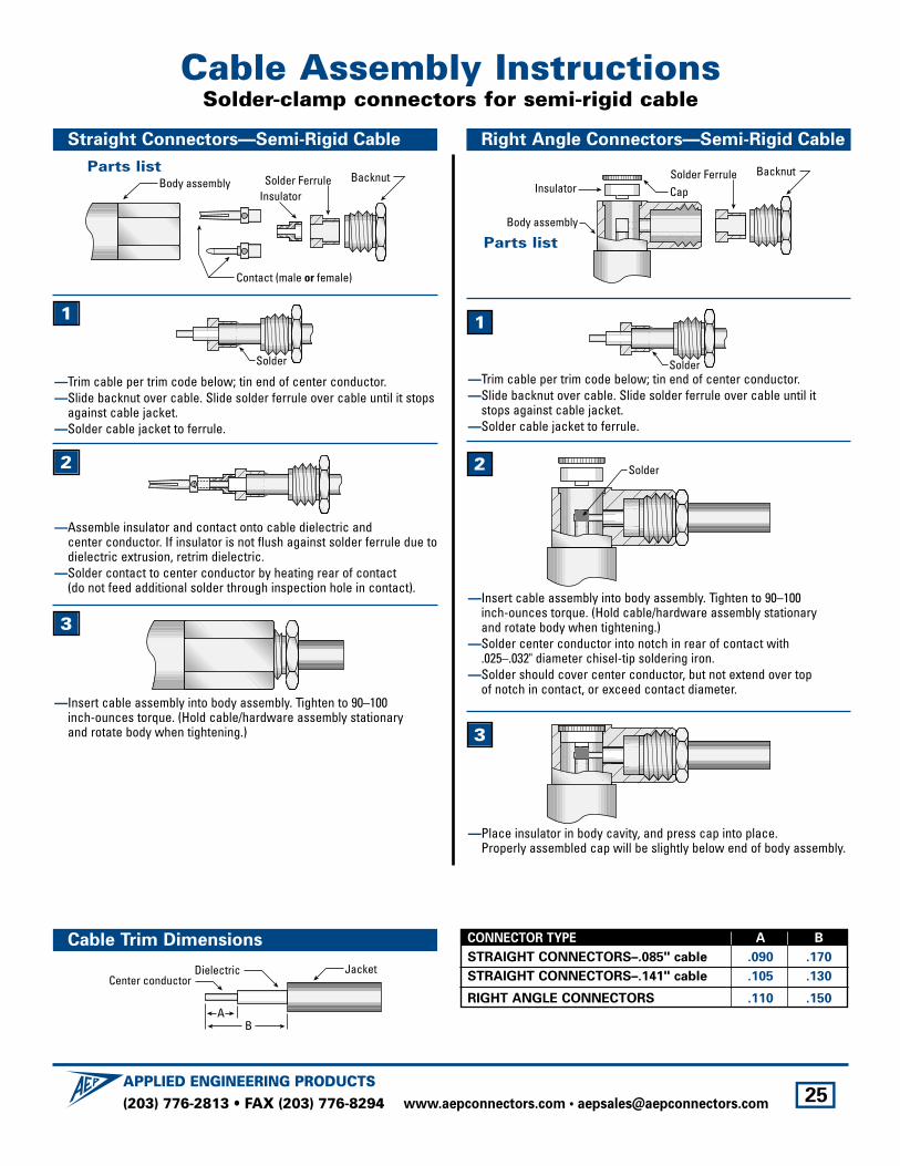
Body assembly Backnut
InsulatorSolder Ferrule
Contact (male or female)
Solder
—Assemble insulator and contact onto cable dielectric and center conductor. If insulator is not flush against solder ferrule due todielectric extrusion, retrim dielectric.
—Solder contact to center conductor by heating rear of contact (do not feed additional solder through inspection hole in contact).
BacknutSolder Ferrule
Body assembly
CapInsulator
Solder
Solder
Straight Connectors—Semi-Rigid Cable
Cable Trim Dimensions
Right Angle Connectors—Semi-Rigid Cable
Parts list
BA
JacketCenter conductor
Dielectric
—Trim cable per trim code below; tin end of center conductor.—Slide backnut over cable. Slide solder ferrule over cable until it stops
against cable jacket.—Solder cable jacket to ferrule.
1
2
3
—Insert cable assembly into body assembly. Tighten to 90–100 inch-ounces torque. (Hold cable/hardware assembly stationary and rotate body when tightening.)
—Place insulator in body cavity, and press cap into place.Properly assembled cap will be slightly below end of body assembly.
—Insert cable assembly into body assembly. Tighten to 90–100 inch-ounces torque. (Hold cable/hardware assembly stationary and rotate body when tightening.)
—Solder center conductor into notch in rear of contact with .025–.032" diameter chisel-tip soldering iron.
—Solder should cover center conductor, but not extend over top of notch in contact, or exceed contact diameter.
—Trim cable per trim code below; tin end of center conductor.—Slide backnut over cable. Slide solder ferrule over cable until it
stops against cable jacket.—Solder cable jacket to ferrule.
1
2
Parts list
CONNECTOR TYPE A B
STRAIGHT CONNECTORS–.085" cable .090 .170
STRAIGHT CONNECTORS–.141" cable .105 .130
RIGHT ANGLE CONNECTORS .110 .150
Cable Assembly InstructionsSolder-clamp connectors for semi-rigid cable
3
(203) 776-2813 • FAX (203) 776-8294APPLIED ENGINEERING PRODUCTS
www.aepconnectors.com • [email protected] 26
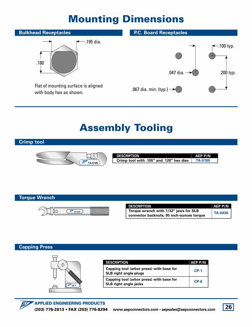
Crimp tool
Bulkhead Receptacles
TA-0105
TA-0436
DESCRIPTION AEP P/N
Crimp tool with .105" and .128" hex dies TA-0105
Torque Wrench
Capping Press
DESCRIPTION AEP P/N
Torque wrench with 7/32" jaws for SLB
connector backnuts; 95 inch-ounces torqueTA-0436
CP-1
Mounting Dimensions
Assembly Tooling
Flat of mounting surface is alignedwith body hex as shown.
.195 dia.
.180
.200 typ.
.100 typ.
.047 dia.
.067 dia. min. (typ.)
P.C. Board Receptacles
DESCRIPTION AEP P/N
Capping tool (arbor press) with base for
SLB right angle plugsCP-1
Capping tool (arbor press) with base for
SLB right angle jacksCP-6
(203) 776-2813 • FAX (203) 776-8294APPLIED ENGINEERING PRODUCTS
www.aepconnectors.com • [email protected] 27
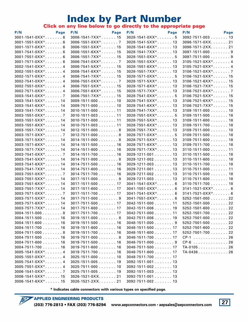
Index by Part NumberClick on any line below to go directly to the appropriate page
P/N Page
3001-1541-0XX*. . . . . . . 63001-1551-0XX*. . . . . . . 63001-1571-0XX*. . . . . . . 63001-7541-0XX*. . . . . . . 63001-7551-0XX*. . . . . . . 63001-7571-0XX*. . . . . . . 63002-1541-0XX*. . . . . . . 43002-1551-0XX*. . . . . . . 43002-1571-0XX*. . . . . . . 43002-7541-0XX*. . . . . . . 43002-7551-0XX*. . . . . . . 43002-7571-0XX*. . . . . . . 43003-1541-0XX*. . . . . . . 73003-1541-5XX* . . . . . . 143003-1541-6XX* . . . . . . 143003-1541-7XX* . . . . . . 143003-1551-0XX*. . . . . . . 73003-1551-5XX* . . . . . . 143003-1551-6XX* . . . . . . 143003-1551-7XX* . . . . . . 143003-1571-0XX*. . . . . . . 73003-1571-5XX* . . . . . . 143003-1571-6XX* . . . . . . 143003-1571-7XX* . . . . . . 143003-7541-0XX*. . . . . . . 73003-7541-5XX* . . . . . . 143003-7541-6XX* . . . . . . 143003-7541-7XX* . . . . . . 143003-7551-0XX*. . . . . . . 73003-7551-5XX* . . . . . . 143003-7551-6XX* . . . . . . 143003-7551-7XX* . . . . . . 143003-7571-0XX*. . . . . . . 73003-7571-5XX* . . . . . . 143003-7571-6XX* . . . . . . 143003-7571-7XX* . . . . . . 143004-1511-000 . . . . . . . . 83004-1511-500 . . . . . . . 163004-1511-600 . . . . . . . 163004-1511-700 . . . . . . . 163004-7511-000 . . . . . . . . 83004-7511-500 . . . . . . . 163004-7511-600 . . . . . . . 163004-7511-700 . . . . . . . 163005-1541-0XX*. . . . . . . 43005-1551-0XX*. . . . . . . 43005-7541-0XX*. . . . . . . 43005-7551-0XX*. . . . . . . 43006-1541-0XX*. . . . . . . 73006-1541-5XX* . . . . . . 153006-1541-6XX* . . . . . . 15
P/N Page
3006-1541-7XX* . . . . . . 153006-1551-0XX*. . . . . . . 73006-1551-5XX* . . . . . . 153006-1551-6XX* . . . . . . 153006-1551-7XX* . . . . . . 153006-7541-0XX*. . . . . . . 73006-7541-5XX* . . . . . . 153006-7541-6XX* . . . . . . 153006-7541-7XX* . . . . . . 153006-7551-0XX*. . . . . . . 73006-7551-5XX* . . . . . . 153006-7551-6XX* . . . . . . 153006-7551-7XX* . . . . . . 153009-1511-000 . . . . . . . 103009-7511-000 . . . . . . . 103010-1511-000 . . . . . . . 113010-1511-003 . . . . . . . 113010-7511-000 . . . . . . . 113010-7511-003 . . . . . . . 113012-1511-000 . . . . . . . . 83012-7511-000 . . . . . . . . 83014-1511-000 . . . . . . . . 83014-1511-500 . . . . . . . 163014-1511-600 . . . . . . . 163014-1511-700 . . . . . . . 163014-7511-000 . . . . . . . . 83014-7511-500 . . . . . . . 163014-7511-600 . . . . . . . 163014-7511-700 . . . . . . . 163017-1511-000 . . . . . . . . 93017-1511-500 . . . . . . . 173017-1511-600 . . . . . . . 173017-1511-700 . . . . . . . 173017-7511-000 . . . . . . . . 93017-7511-500 . . . . . . . 173017-7511-600 . . . . . . . 173017-7511-700 . . . . . . . 173019-1511-000 . . . . . . . . 83019-1511-500 . . . . . . . 163019-1511-600 . . . . . . . 163019-1511-700 . . . . . . . 163019-7511-000 . . . . . . . . 83019-7511-500 . . . . . . . 163019-7511-600 . . . . . . . 163019-7511-700 . . . . . . . 163025-1511-000 . . . . . . . 103025-1511-005 . . . . . . . 193025-7511-000 . . . . . . . 103025-7511-005 . . . . . . . 193026-1521-0XX. . . . . . . 213026-1521-2XX. . . . . . . 21
P/N Page
3028-1541-0XX*. . . . . . . 53028-1541-5XX* . . . . . . 133028-1541-6XX* . . . . . . 133028-1541-7XX* . . . . . . 133028-1551-0XX*. . . . . . . 53028-1551-5XX* . . . . . . 133028-1551-6XX* . . . . . . 133028-1551-7XX* . . . . . . 133028-1571-0XX*. . . . . . . 53028-1571-5XX* . . . . . . 133028-1571-6XX* . . . . . . 133028-1571-7XX* . . . . . . 133028-7541-0XX*. . . . . . . 53028-7541-5XX* . . . . . . 133028-7541-6XX* . . . . . . 133028-7541-7XX* . . . . . . 133028-7551-0XX*. . . . . . . 53028-7551-5XX* . . . . . . 133028-7551-6XX* . . . . . . 133028-7551-7XX* . . . . . . 133028-7571-0XX*. . . . . . . 53028-7571-5XX* . . . . . . 133028-7571-6XX* . . . . . . 133028-7571-7XX* . . . . . . 133029-1211-001 . . . . . . . 133029-1211-002 . . . . . . . 133029-1211-003 . . . . . . . 133029-7211-001 . . . . . . . 133029-7211-002 . . . . . . . 133029-7211-003 . . . . . . . 133041-1541-0XX*. . . . . . . 63041-1551-0XX*. . . . . . . 63041-7541-0XX*. . . . . . . 63041-7551-0XX*. . . . . . . 63042-1511-000 . . . . . . . 113042-1511-006 . . . . . . . 193042-7511-000 . . . . . . . 113042-7511-006 . . . . . . . 193048-1511-000 . . . . . . . . 93048-1511-500 . . . . . . . 173048-1511-600 . . . . . . . 173048-1511-700 . . . . . . . 173048-7511-000 . . . . . . . . 93048-7511-500 . . . . . . . 173048-7511-600 . . . . . . . 173048-7511-700 . . . . . . . 173092-1511-001 . . . . . . . 133092-1511-002 . . . . . . . 133092-1511-003 . . . . . . . 133092-7511-001 . . . . . . . 133092-7511-002 . . . . . . . 13
P/N Page
3092-7511-003 . . . . . . . 133096-1571-0XX. . . . . . . 213096-1571-2XX. . . . . . . 213097-1511-000 . . . . . . . . 93097-7511-000 . . . . . . . . 93105-1521-0XX*. . . . . . . 43105-7521-0XX*. . . . . . . 43106-1521-0XX*. . . . . . . 73106-1521-5XX* . . . . . . 153106-1521-6XX* . . . . . . 153106-1521-7XX* . . . . . . 153106-7521-0XX*. . . . . . . 73106-7521-5XX* . . . . . . 153106-7521-6XX* . . . . . . 153106-7521-7XX* . . . . . . 153109-1511-000 . . . . . . . 103109-1511-500 . . . . . . . 183109-1511-600 . . . . . . . 183109-1511-700 . . . . . . . 183109-7511-000 . . . . . . . 103109-7511-500 . . . . . . . 183109-7511-600 . . . . . . . 183109-7511-700 . . . . . . . 183110-1511-000 . . . . . . . 113110-1511-500 . . . . . . . 183110-1511-600 . . . . . . . 183110-1511-700 . . . . . . . 183110-7511-000 . . . . . . . 113110-7511-500 . . . . . . . 183110-7511-600 . . . . . . . 183110-7511-700 . . . . . . . 183141-1521-0XX*. . . . . . . 63141-7521-0XX*. . . . . . . 65252-1501-000 . . . . . . . 225252-1501-500 . . . . . . . 225252-1501-600 . . . . . . . 225252-1501-700 . . . . . . . 225252-7501-000 . . . . . . . 225252-7501-500 . . . . . . . 225252-7501-600 . . . . . . . 225252-7501-700 . . . . . . . 22CP-1 . . . . . . . . . . . . . . 26CP-6 . . . . . . . . . . . . . . 26TA-0105 . . . . . . . . . . . . 26TA-0436 . . . . . . . . . . . . 26
* Indicates cable connectors with various types on specified page.

(203) 776-2813 • FAX (203) 776-8294APPLIED ENGINEERING PRODUCTS
www.aepconnectors.com • [email protected] 28
About Applied Engineering ProductsSince our foundation in 1973, we have always believed that having our customers take a look “inside AEP” is important in
fostering strong vendor/customer relationships. We are proud of our physical plant and equipment, but even more so of our
dedicated staff. When customers see first-hand how AEP’s people keep a constant focus on maintaining and improving
customer service and satisfaction, the rea-
son for our consistently strong on-time
delivery and quality records becomes clear.
We invite you to see for yourself. Call us to
arrange a plant tour—or, if you can’t make
a visit, ask for your copy of INSIDE AEP,
our facilities and capabilities brochure.

29
The SLB connectors in this brochure are only part of our complete line of subminiature coaxial connectors and cable assemblies, including:
• SMA
• SMB
• SMC
• SSMB
• SSMC
• SLB (Slide-on version of SMB)
• SSLB (Slide-on version of SSMB)
• 75Ω Snap-on mating
• 75Ω Screw-on mating
• Adapters within and between series
• Flexible cable assemblies
• Semi-rigid cable assemblies
• And over 100 styles of MIL-PRF-39012 QPL connectors in series SMA, SMB, and SMC
Call for your copy of our 184-page full catalog to see them all.
APPLIED ENGINEERING PRODUCTS104 John W. Murphy Drive • P.O. Box 510 • New Haven, CT 06513
(203) 776-2813 • FAX (203) 776-8294www.aepconnectors.com • e-mail: [email protected]
Related Documents