INDUSTRIAL TRAINING REPORT ON PROGRAMMABLE LOGIC CONTROLLER AND SCADA In partial fulfilment of the requirement for the award of the degree Of BACHELOR OF TECHNOLOGY IN ELECTRICAL AND ELECTRONICS ENGINEERING BY GURU GOBIND SINGH INDRAPRASTHA UNIVERSITY Submitted by : MANOJ KUMAR (13715604914) NORTHERN INDIA ENGINEERING COLLEGE SHASTRI PARK , DELHI 110053 AUGUST , 2016

Welcome message from author
This document is posted to help you gain knowledge. Please leave a comment to let me know what you think about it! Share it to your friends and learn new things together.
Transcript
INDUSTRIAL TRAINING REPORT
ON
PROGRAMMABLE LOGIC CONTROLLER
AND SCADA
In partial fulfilment of the requirement for the award of the degree
Of
BACHELOR OF TECHNOLOGY
IN
ELECTRICAL AND ELECTRONICS ENGINEERING
BY
GURU GOBIND SINGH INDRAPRASTHA UNIVERSITY
Submitted by :
MANOJ KUMAR
(13715604914)
NORTHERN INDIA ENGINEERING COLLEGE
SHASTRI PARK , DELHI 110053
AUGUST , 2016
Acknowledgement I would like to thank SOFCON INDIA PVT. LIMITED, NOIDA for providing me exposure to the
whole Scada & PLCs System. I’d also like to thank Er. AKASH GAURAV (E.E.E), and Er.
ABHIMANYU SINGH YADAV (E.E.E.), for their enduring support and guidance throughout
the training. I am very grateful to the whole Electrical and Electronics Department for their support
and guidance. I am also very thankful to the Trainers near the machineries and the H.O.D of (E.E.E) for their
support to my training.
[2]
CERTIFICATE
This training report is a genuine works by Mr. MANOJ KUMAR, B-Tech 3rd yr, Electrical and
Electronics Engg. The report was made under my supervision, and I express my delight on it
successful completion. I am also very happy to have offered her guidance whenever it was
required.
I wish her success in all her future endeavors.
(ER. AKASH GAURAV)
Trainee Engineer
[3]
Preface An industrial SCADA & PLCs system is used for the development of the controls of machinery. This
paper describes the SCADA & PLCs systems in terms of their architecture, their interface to the process
hardware, the functionality and the application development facilities they provide. Some attention is
also paid to the industrial standards to which they abide their planned evolution as well as the potential
benefits of their use.
MANOJ KUMAR
B. TECH, 3rd year (E.E.E)
ROLL NO. 13715604914 [4]
CONTENTS
CHAPTER 1 :: INRODUCTION ……………………………………………………..........…….6-7
1.1 :: PLC AND OVERVIEW………………………………………………………6-7
1.2 :: FEATURES OF PLC…………………………………………………………8-9
1.3 :: WIRING IN A PLC…………………………………………………………...10
1.4 :: GENERATION OF I/P SIGNAL…………………………………………......11
1.5 :: GENERATION OF O/P SIGNAL …………………………………………..12-13
1.6 :: PLC COMPARED WITH CONTROL SYSTEMS………………………….13-14
1.7 :: DIGITAL AND ANALOG SIGNAL………………………………………....15-16
CHAPTER 2 :: PROGRAMMING WITH PLC…………………………………………………….17
2.1 :: LADDER LOGIC…………………………………………………………… 17-19
2.2 :: GENERALLY USED SYMBOLS USED FOR PLC PROGRAMMING…..19-25
CHAPTER 3 :: PROGRAMMIG FOR START / STOP OF LED OF KIT BY PLC………...........26
3.1 :: STARTING OF LEDs ……………………………………………………….26-28
3.2 :: LOGIC FOR CONTINOUS GLOWING OF LED , BUTTON RELEASES..28-29
3.3 :: TO STOP LEDs ……………………………………………………………...29-30
CHAPTER 4 :: MEANING OF SCADA …………………………………………………………..31
4.1 :: HARDWARE ARCHITECTURE…………………………………………......32
4.2 :: COMMUNICATIONS………………………………………………………..33-34
4.3 :: FUNCTIONALITY …………………………………………………………….35
4.4 :: ALARM HANDLEING………………………………………………………...36
4.5 :: LOGGING……………………………………………………………………...37
4.6 :: REPORT GENERATION…………………………………………………...…37
4.7 :: AUTOMATION …………………………………………………………...…..37
CHAPTER 5:: APPLICATIONS OF SCADA …………………………………………………….38
5.1 :: CONFIGURATION …………………………………………………………...39
5.2 :: DEVELOPMENT TOOL ……………………………………………………...40
5.3 :: EVOLUTION ……………………………………………………………….…41
5.4 :: ENGINEERING…………………………………………………………….….42
5.5 :: POTENTIAL BENEFIT OF SCADA …………………………………….… 44-45
REFERENCES ……………………………………………………………………………………..46
CONCLUSION……………………………………………………………………………………..47
[5]
CHAPTER 1 1.Introduction 1.1 PLC An Overview A Programmable Logic Controller, PLC, or Programmable Controller is a digital computer used
for automation of industrial processes, such as control of machinery on factory assembly lines.
Unlike general-purpose computers, the PLC is designed for multiple inputs and output
arrangements, extended temperature ranges, immunity to electrical noise, and resistance to
vibration and impact. Programs to control machine operation are typically stored in battery-backed
or non- volatile memory. A PLC is an example of a real system since output results must be
produced in response to input conditions within a bounded time, otherwise unintended operation
will result.
PLC and Programmable Logic Controller are registered trademarks of the Allen Bradley
Company.
SCADA is Widely used in industry for Supervisory Control and Data Acquisition of industrial
processes, SCADA systems are now also penetrating the experimental physics laboratories for the
controls of ancillary systems such as cooling, ventilation, power distribution, etc. More
recently they were also applied for the controls of smaller size particle detectors such as the L3
moon detector and the NA48 experiment, to name just two examples at CERN.
SCADA systems have made substantial progress over the recent years in terms of functionality,
scalability, performance and openness such that they are an alternative to in house development
even for very demanding and complex control systems as those of physics experiments.
[6]
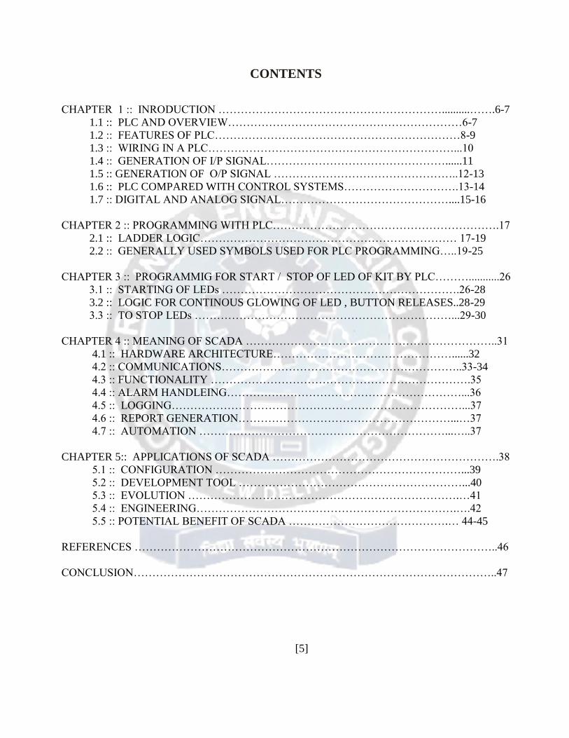
FIG 1.1
Block Daigram Of The Plc
[7]
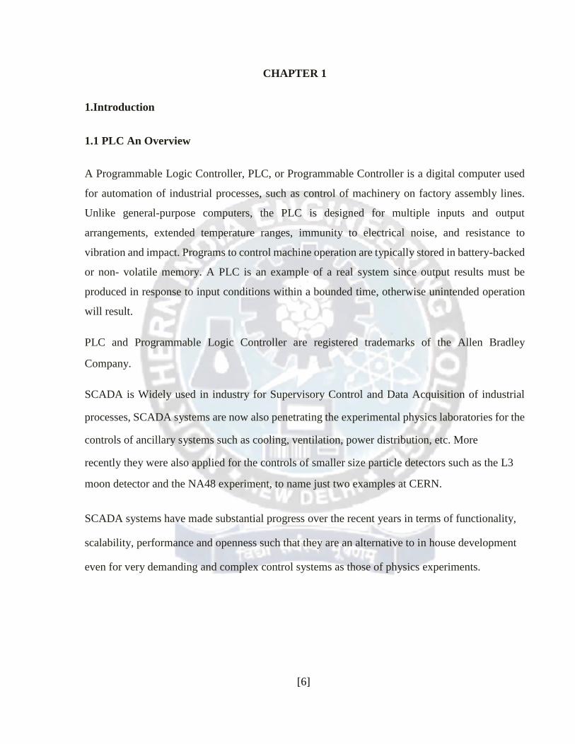
1.2.Features of PLCs
FIG 1.2
Photograph showing several input and output modules of a single Allen-Bradley PLC.
With each module having sixteen "points" of either input or output, this PLC has the ability to
monitor and control dozens of devices. Fit into a control cabinet, a PLC takes up little room,
especially considering the equivalent space that would be needed by electromechanical relays to
perform the same functions:
[8]

The main difference from other computers is that PLC are armored for severe condition (dust,
moisture, heat, cold, etc) and has the facility for extensive input/output (I/O) arrangements. These
connect the PLC to sensors and actuators. PLCs read limit switches, analog process variables
(such as temperature and pressure), and the positions of complex positioning systems. Some even
use machine vision. On the actuator side, PLCs operate electronic LEDs, pneumatic or hydraulic
cylinders, magnetic relays or solenoids, or analog outputs. The input/output arrangements may
be built into a simple PLC, or the PLC may have external I/O modules attached to a computer
network that plugs into the PLC.
Many of the earliest PLCs expressed all decision making logic in simple ladder logic which
appeared similar to electrical schematic diagrams. The electricians were quite able to trace out
circuit problems with schematic diagrams using ladder logic. This program notation was chosen
to reduce training demands for the existing technicians. Other early PLCs used a form of
instruction list programming, based on a stack-based logic solver.
The functionality of the PLC has evolved over the years to include sequential relay control, motion
control, process control, distributed control systems and networking. The data handling, storage,
processing power and communication capabilities of some modern PLCs are approximately
equivalent to desktop computers.
[9]
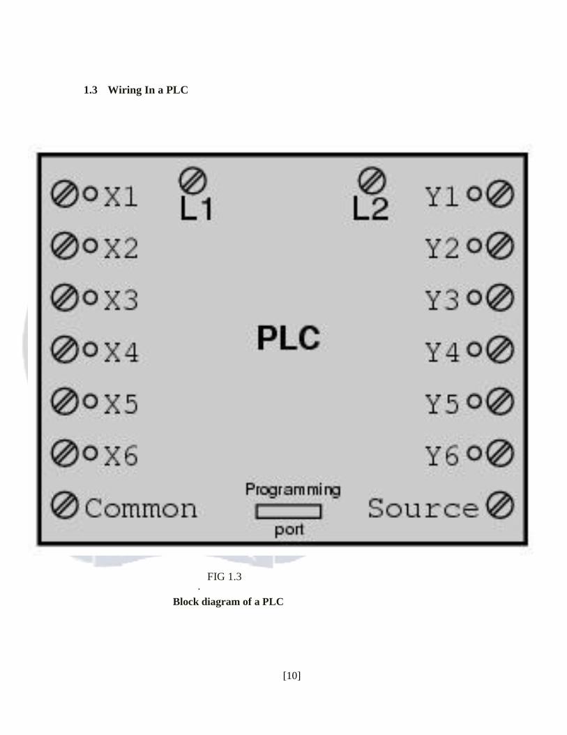
1.3 Wiring In a PLC
FIG 1.3 ·
Block diagram of a PLC
[10]
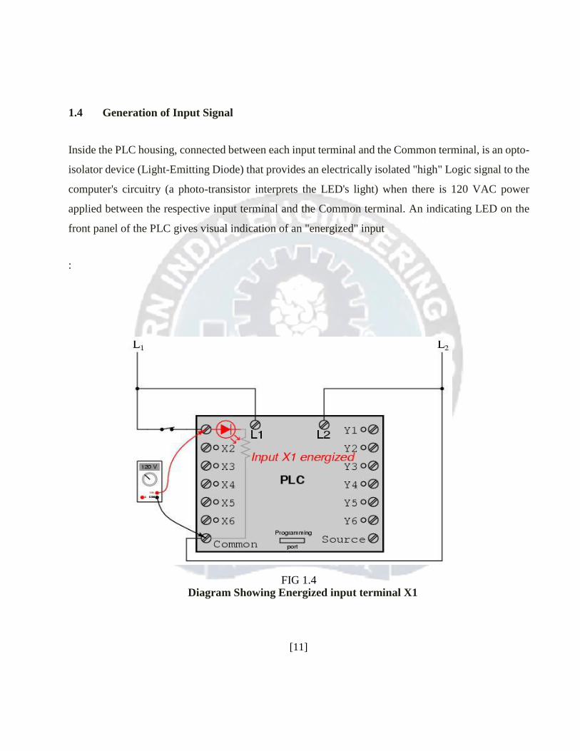
1.4 Generation of Input Signal
Inside the PLC housing, connected between each input terminal and the Common terminal, is an opto-
isolator device (Light-Emitting Diode) that provides an electrically isolated "high" Logic signal to the
computer's circuitry (a photo-transistor interprets the LED's light) when there is 120 VAC power
applied between the respective input terminal and the Common terminal. An indicating LED on the
front panel of the PLC gives visual indication of an "energized" input
:
FIG 1.4
Diagram Showing Energized input terminal X1 [11]

1.5 Generation of Output Signal
Output signals are generated by the PLC's computer circuitry activating a switching device (transistor,
TRIAC, or even an electromechanical relay), connecting the "Source" terminal to any of the "Y-"
labeled output terminals. The "Source" terminal, correspondingly, is usually connected to the L1 side
of the 120 VAC power source. As with each input, an indicating LED on the front panel of the PLC
gives visual indication of an "energized" output
In this way, the PLC is able to interface with real-world devices such as switches and solenoids.
The actual logic of the control system is established inside the PLC by means of a computer program.
This program dictates which output gets energized under which input conditions. Although the
program itself appears to be a ladder logic diagram, with switch and relay symbols, there are no actual
switch contacts or relay LEDs operating inside the PLC to create the logical relationships between
input and output. These are imaginary contacts and LEDs, if you will. The program is entered and
viewed via a personal computer connected to the PLC's programming port.
[12]

FIG 1.5
Diagram Showing Energized Output Y1
1.6 PLC compared with other control systems
PLCs are well-adapted to a certain range of automation tasks. These are typically industrial processes in
manufacturing where the cost of developing and maintaining the automation system is high relative to the
total cost of the automation, and where changes to the system would be expected during its operational
life. PLCs contain input and output devices compatible with industrial pilot devices and controls; little
electrical design is required, and the design problem centers on expressing the desired sequence of
operations in ladder logic (or function chart) notation. PLC applications are typically highly customized
systems so the cost of a packaged PLC is low compared to the cost of a specific custom-built controller
design. For high volume or very simple fixed automation tasks, different techniques are used.
A microcontroller-based design would be appropriate where hundreds or thousands of units will be
produced and so the development cost (design of power supplies and input/output hardware) can be
spread over many sales, and where the end-user would not need to alter the control. Automotive
applications are an example; millions of units are built each year, and very few end-users alter the
programming of these controllers. However, some specialty vehicles such as transit busses
[13]
economically use PLCs instead of custom-designed controls, because the volumes are low and the
development cost would be uneconomic.
PLCs may include logic for single-variable feedback analog control loop, a "proportional, integral,
derivative" or "PID controller." A PID loop could be used to control the temperature of a manufacturing
process, for example. Historically PLCs were usually configured with only a few analog control loops;
where processes required hundreds or thousands of loops, a distributed control system (DCS) would
instead be used. However, as PLCs have become more powerful, the boundary between DCS and PLC
applications has become less clear.
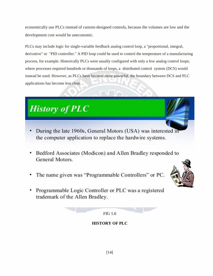
FIG 1.6
HISTORY OF PLC [14]
1.7 Digital and analog signals Digital or discrete signals behave as binary switches, yielding simply an On or Off signal (1 or 0, True or
False, respectively). Pushbuttons, limit switches, and photoelectric sensors are examples of devices
providing a discrete signal. Discrete signals are sent using either voltage or current, where a specific range
is designated as on and another as off. For example, a PLC might use 24 V DC I/O, with values above 22
V DC representing off, values below 2VDC representing off, and intermediate values undefined. Initially,
PLCs had only discrete I/O.
Analog signals are like volume controls, with a range of values between zero and full-scale. These
are typically interpreted as integer values (counts) by the PLC, with various ranges of accuracy
depending on the device and the number of bits available to store the data. As PLCs typically use
16-bit signed binary processors, the integer values are limited between -32,768 and +32,767.
Pressure, temperature, flow, and weight are often represented by analog signals. Analog signals
can use voltage or current with a magnitude proportional to the value of the process signal. For
example, an analog 4-20 mA or 0 - 10 V input would be converted into an integer value of 0 -
32767.
Current inputs are less sensitive to electronic noise (i.e. from welders or electronic LEDs starts)
than voltage inputs.
[15]
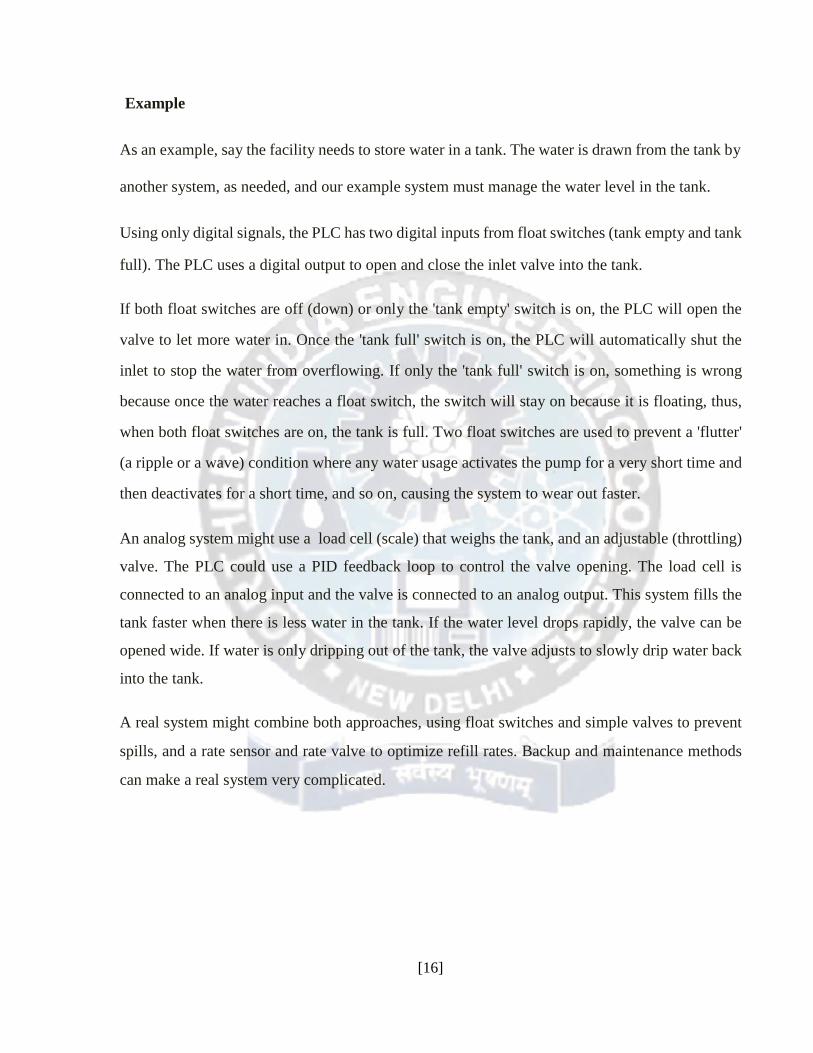
Example As an example, say the facility needs to store water in a tank. The water is drawn from the tank by
another system, as needed, and our example system must manage the water level in the tank.
Using only digital signals, the PLC has two digital inputs from float switches (tank empty and tank
full). The PLC uses a digital output to open and close the inlet valve into the tank.
If both float switches are off (down) or only the 'tank empty' switch is on, the PLC will open the
valve to let more water in. Once the 'tank full' switch is on, the PLC will automatically shut the
inlet to stop the water from overflowing. If only the 'tank full' switch is on, something is wrong
because once the water reaches a float switch, the switch will stay on because it is floating, thus,
when both float switches are on, the tank is full. Two float switches are used to prevent a 'flutter'
(a ripple or a wave) condition where any water usage activates the pump for a very short time and
then deactivates for a short time, and so on, causing the system to wear out faster.
An analog system might use a load cell (scale) that weighs the tank, and an adjustable (throttling)
valve. The PLC could use a PID feedback loop to control the valve opening. The load cell is
connected to an analog input and the valve is connected to an analog output. This system fills the
tank faster when there is less water in the tank. If the water level drops rapidly, the valve can be
opened wide. If water is only dripping out of the tank, the valve adjusts to slowly drip water back
into the tank.
A real system might combine both approaches, using float switches and simple valves to prevent
spills, and a rate sensor and rate valve to optimize refill rates. Backup and maintenance methods
can make a real system very complicated.
[16]

CHAPTER 2
Programming with PLC Early PLCs, up to the mid-1980s, were programmed using proprietary programming panels or special-
purpose programming terminals, which often had dedicated function keys representing the various logical
elements of PLC programs. Programs were stored on cassette tape cartridges. Facilities for printing and
documentation were very minimal due to lack of memory capacity. More recently, PLC programs are
typically written in a special application on a personal computer, then downloaded by a direct-connection
cable or over a network to the PLC. The very oldest PLCs used non-volatile magnetic core memory but
now the program is stored in the PLC either in battery-backed-up RAM or some other non-volatile flash
memory.
Early PLCs were designed to be used by electricians who would learn PLC programming on the job.
These PLCs were programmed in "ladder logic", which strongly resembles a schematic diagram of
relay logic. Modern PLCs can be programmed in a variety of ways, from ladder logic to more
traditional programming languages such as BASIC and C. Another method is State Logic, a Very
High Level Programming Language designed to program PLCs based on State Transition Diagrams.
2.1 Ladder logic Ladder logic is a method of drawing electrical logic schematics. It is now a graphical language
very popular for programming Programmable Logic Controllers (PLCs). It was originally
invented to describe logic made from relays. The name is based on the observation that programs
in this language resemble ladders, with two vertical "rails" and a series of horizontal "rungs"
between them.
A program in ladder logic, also called a ladder diagram, is similar to a schematic for a set of relay
circuits. An argument that aided the initial adoption of ladder logic was that a wide variety of
engineers and technicians would be able to understand and use it without much additional
[17]

training, because of the resemblance to familiar hardware systems. (This argument has become less
relevant given that most ladder logic programmers have a software background in more conventional
programming languages, and in practice implementations of ladder logic have characteristics — such
as sequential execution and support for control flow features — that make the analogy to hardware
somewhat imprecise.)
Ladder logic is widely used to program PLCs, where sequential control of a process or manufacturing
operation is required. Ladder logic is useful for simple but critical control systems, or for reworking
old hardwired relay circuits. As programmable logic controllers became more sophisticated it has also
been used in very complex automation systems.
Ladder logic can be thought of as a rule-based language, rather than a procedural language. A "rung" in
the ladder represents a rule. When implemented with relays and other electromechanical devices, the
various rules "execute" simultaneously and immediately. When implemented in a programmable logic
controller, the rules are typically executed sequentially by software, in a loop. By executing the loop fast
enough, typically many times per second, the effect of simultaneous and immediate execution is obtained.
In this way it is similar to other rule-based languages, like spreadsheets or SQL. However, proper use of
programmable controllers requires understanding the limitations of the execution order of rungs.
Example of a simple ladder logic program The language itself can be seen as a set of connections between logical checkers (relay contacts) and
actuators (LEDs). If a path can be traced between the left side of the rung and the output, through
asserted (true or "closed") contacts, the rung is true and the output LED storage bit is asserted (1) or
true. If no path can be traced, then the output is false (0) and the "LED" by analogy to electromechanical
relays is considered "de-energized". The analogy between logical propositions and relay contact status
is due to Claude Shannon.
Ladder logic has "contacts" that "make" or "break" "circuits" to control "LEDs." Each LED or contact
corresponds to the status of a single bit in the programmable controller's memory. Unlike
electromechanical relays, a ladder program can refer any number of times to the status of a single bit,
equivalent to a relay with an indefinitely large number of contacts.
[18]
So-called "contacts" may refer to inputs to the programmable controller from physical devices
such as pushbuttons and limit switches, or may represent the status of internal storage bits which
may be generated elsewhere in the program.
Each rung of ladder language typically has one LED at the far right. Some manufacturers may
allow more than one output LED on a rung.
--( )-- a regular LED, true when its rung is true --(\)-- a "not" LED, false when its rung is true --[ ]-- A regular contact, true when its LED is true (normally false) --[\]-- A "not" contact, false when its LED is true (normally true) The "LED" (output of a rung) may represent a physical output which operates some device
connected to the programmable controller, or may represent an internal storage bit for use
elsewhere in the program.
2.2 Generally Used Instructions & symbol For PLC Programming Input Instruction --[ ]-- This Instruction is Called IXC or Examine If Closed.
ie; If a NO switch is actuated then only this instruction will be true. If a NC switch
is actuated then this instruction will not be true and hence output will not be generated.
--[\]-- This Instruction is Called IXO or Examine If Open
[19]

ie; If a NC switch is actuated then only this instruction will be true. If a NC switch is actuated then this
instruction will not be true and hence output will not be generated.
Output Instruction
--( )-- This Instruction Shows the States of Output.
ie; If any instruction either XIO or XIC is true then output will be high. Due to high
output a 24 volt signal is generated from PLC processor.
Rung Rung is a simple line on which instruction are placed and logics are created E.g.; --------------------------------------------- Here is an example of what one rung in a ladder logic program might look like. In real life, there
may be hundreds or thousands of rungs.
For example
1. ----[ ]--------- |----- ----[ ]-- | --( )--
X | Y | S
| |
|----- ----[ ]-- |
Z
The above realises the function: S = X AND (Y OR Z) Typically, complex ladder logic is 'read' left to right and top to bottom. As each of the lines (or
rungs) are evaluated the output LED of a rung may feed into the next stage of the ladder as an
input. In a complex system there will be many "rungs" on a ladder, which are numbered in order
of evaluation.
1. ----[ ]-----------|---[ ]---|----( )--
[20]
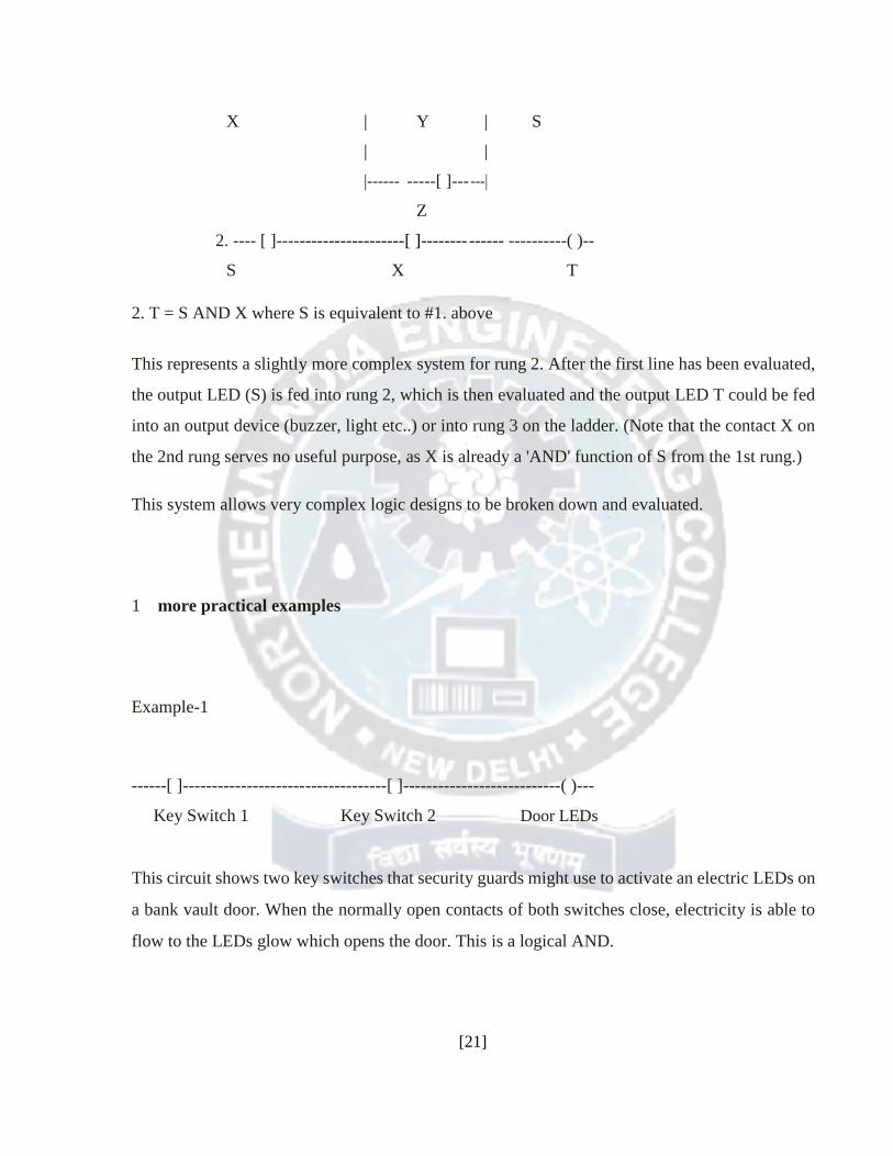
X | Y | S
| |
|------ -----[ ]--- ---|
Z
2. ---- [ ]---- ------------------ [ ]-------- ------ ----------( )--
S X T
2. T = S AND X where S is equivalent to #1. above This represents a slightly more complex system for rung 2. After the first line has been evaluated,
the output LED (S) is fed into rung 2, which is then evaluated and the output LED T could be fed
into an output device (buzzer, light etc..) or into rung 3 on the ladder. (Note that the contact X on
the 2nd rung serves no useful purpose, as X is already a 'AND' function of S from the 1st rung.)
This system allows very complex logic designs to be broken down and evaluated.
1 more practical examples
Example-1
------[ ]-----------------------------------[ ]---------------------------( )---
Key Switch 1 Key Switch 2 Door LEDs
This circuit shows two key switches that security guards might use to activate an electric LEDs on
a bank vault door. When the normally open contacts of both switches close, electricity is able to
flow to the LEDs glow which opens the door. This is a logical AND.
[21]
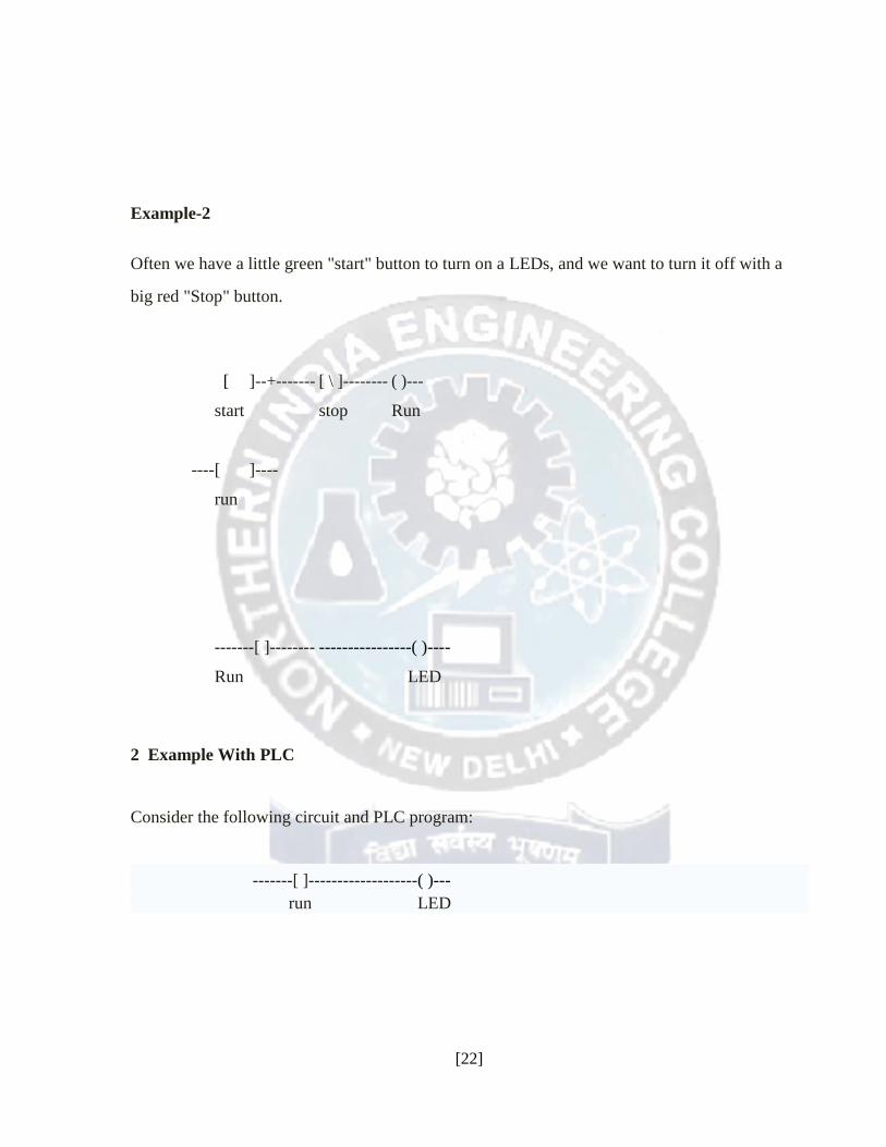
Example-2 Often we have a little green "start" button to turn on a LEDs, and we want to turn it off with a
big red "Stop" button.
[ ]-- +------- [ \ ]-------- ( )---
start stop Run
---- [ ]-- --
run
-------[ ]-------- ----------------( )----
Run LED
2 Example With PLC
Consider the following circuit and PLC program:
-------[ ]------------------- ( )---
run LED
[22]
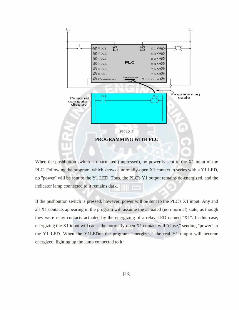
FIG 2.1
PROGRAMMING WITH PLC
When the pushbutton switch is unactuated (unpressed), no power is sent to the X1 input of the
PLC. Following the program, which shows a normally-open X1 contact in series with a Y1 LED,
no "power" will be sent to the Y1 LED. Thus, the PLC's Y1 output remains de-energized, and the
indicator lamp connected to it remains dark.
If the pushbutton switch is pressed, however, power will be sent to the PLC's X1 input. Any and
all X1 contacts appearing in the program will assume the actuated (non-normal) state, as though
they were relay contacts actuated by the energizing of a relay LED named "X1". In this case,
energizing the X1 input will cause the normally-open X1 contact will "close," sending "power" to
the Y1 LED. When the Y1LEDof the program "energizes," the real Y1 output will become
energized, lighting up the lamp connected to it:
[23]
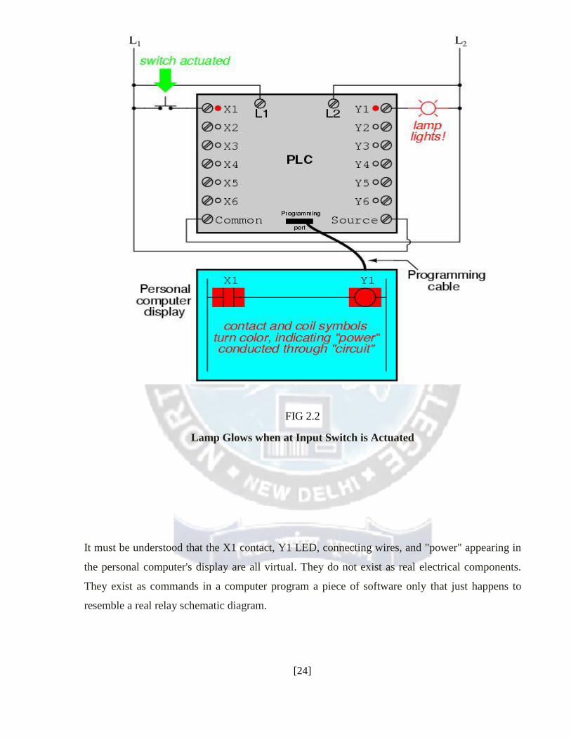
FIG 2.2
Lamp Glows when at Input Switch is Actuated
It must be understood that the X1 contact, Y1 LED, connecting wires, and "power" appearing in
the personal computer's display are all virtual. They do not exist as real electrical components.
They exist as commands in a computer program a piece of software only that just happens to
resemble a real relay schematic diagram.
[24]
Equally important to understand is that the personal computer used to display and edit the PLC's
program is not necessary for the PLC's continued operation. Once a program has been loaded to
the PLC from the personal computer, the personal computer may be unplugged from the PLC, and
the PLC will continue to follow the programmed commands. I include the personal computer
display in these illustrations for your sake only, in aiding to understand the relationship between
real-life conditions (switch closure and lamp status) and the program's status ("power" through
virtual contacts and virtual LEDs).
The true power and versatility of a PLC is revealed when we want to alter the behavior of a control
system. Since the PLC is a programmable device, we can alter its behavior by changing the commands
we give it, without having to reconfigure the electrical components connected to it. For example,
suppose we wanted to make this switch-and-lamp circuit function in an inverted fashion: push the
button to make the lamp turn off, and release it to make it turn on. The "hardware" solution would
require that a normally-closed pushbutton switch be substituted for the normally-open switch currently
in place. The "software" solution is much easier: just alter the program so that contact X1 is normally-
closed rather than normally-open.
[25]
CHAPTER 3
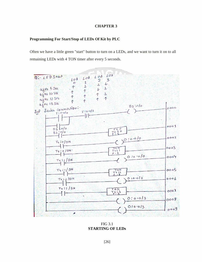
Programming For Start/Stop of LEDs Of Kit by PLC
Often we have a little green "start" button to turn on a LEDs, and we want to turn it on to all
remaining LEDs with 4 TON timer after every 5 seconds.
FIG 3.1
STARTING OF LEDs
[26]
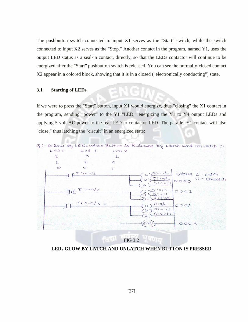
The pushbutton switch connected to input X1 serves as the "Start" switch, while the switch
connected to input X2 serves as the "Stop." Another contact in the program, named Y1, uses the
output LED status as a seal-in contact, directly, so that the LEDs contactor will continue to be
energized after the "Start" pushbutton switch is released. You can see the normally-closed contact
X2 appear in a colored block, showing that it is in a closed ("electronically conducting") state.
3.1 Starting of LEDs
If we were to press the "Start" button, input X1 would energize, thus "closing" the X1 contact in
the program, sending "power" to the Y1 "LED," energizing the Y1 to Y4 output LEDs and
applying 5 volt AC power to the real LED to contactor LED. The parallel Y1 contact will also
"close," thus latching the "circuit" in an energized state:
FIG 3.2
LEDs GLOW BY LATCH AND UNLATCH WHEN BUTTON IS PRESSED
[27]
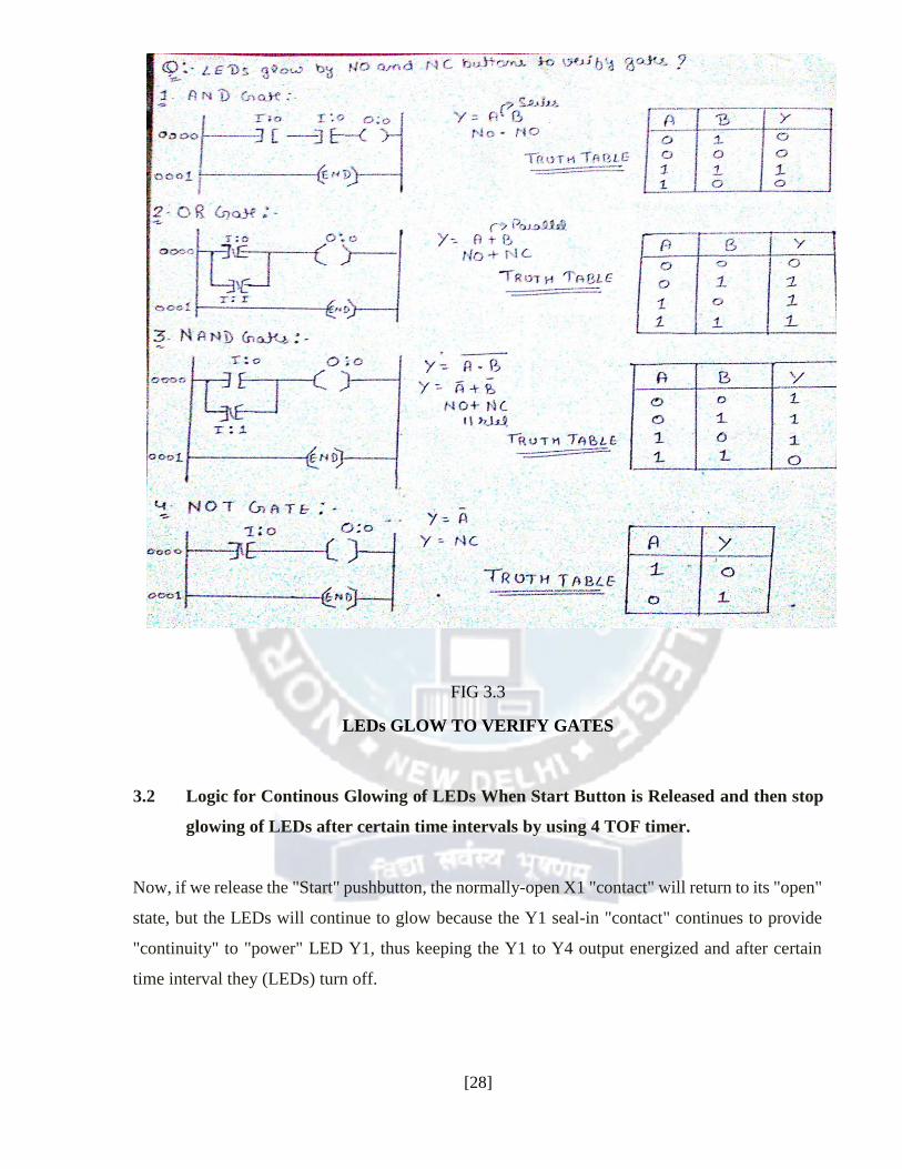
FIG 3.3
LEDs GLOW TO VERIFY GATES
3.2 Logic for Continous Glowing of LEDs When Start Button is Released and then stop
glowing of LEDs after certain time intervals by using 4 TOF timer.
Now, if we release the "Start" pushbutton, the normally-open X1 "contact" will return to its "open"
state, but the LEDs will continue to glow because the Y1 seal-in "contact" continues to provide
"continuity" to "power" LED Y1, thus keeping the Y1 to Y4 output energized and after certain
time interval they (LEDs) turn off.
[28]
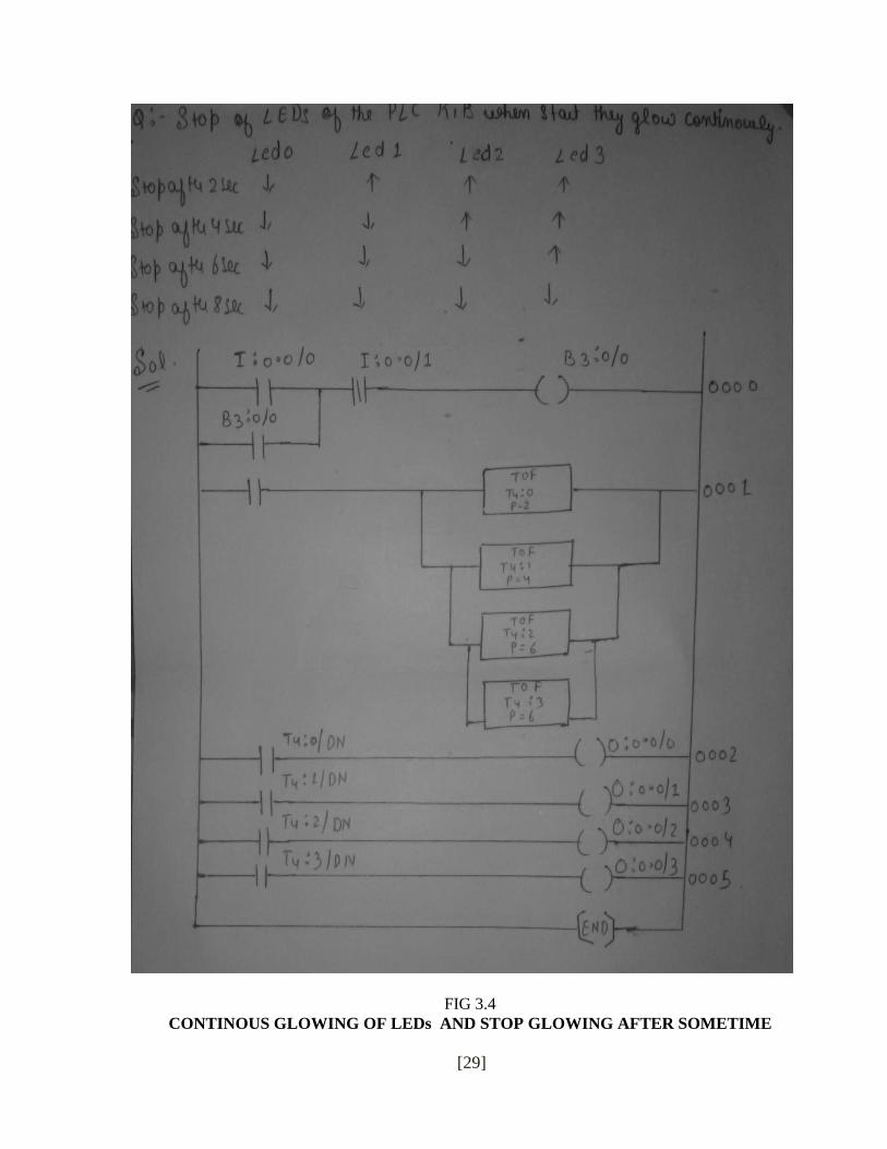
FIG 3.4
CONTINOUS GLOWING OF LEDs AND STOP GLOWING AFTER SOMETIME
[29]
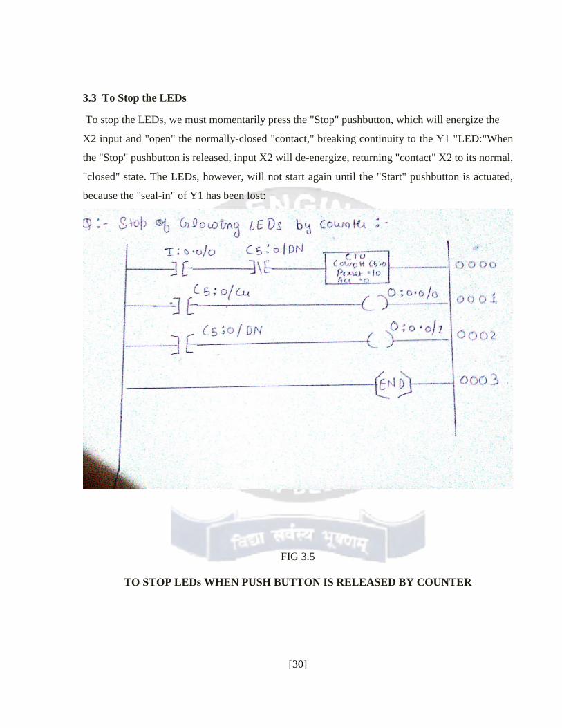
3.3 To Stop the LEDs To stop the LEDs, we must momentarily press the "Stop" pushbutton, which will energize the
X2 input and "open" the normally-closed "contact," breaking continuity to the Y1 "LED:"When
the "Stop" pushbutton is released, input X2 will de-energize, returning "contact" X2 to its normal,
"closed" state. The LEDs, however, will not start again until the "Start" pushbutton is actuated,
because the "seal-in" of Y1 has been lost:
[29]
FIG 3.5
TO STOP LEDs WHEN PUSH BUTTON IS RELEASED BY COUNTER
[30]
CHAPTER 4
Meaning of SCADA SCADA stands for Supervisory Control and Data Acquisition. As the name indicates, it is not a full
control system, but rather focuses on the supervisory level. As such, it is a purely software package
that is positioned on top of hardware to which it is interfaced, in general via Programmable Logic
Controllers (PLCs), or other commercial hardware modules.
SCADA systems are used not only in industrial processes: e.g. steel making, power generation
(conventional and nuclear) and distribution, chemistry, but also in some experimental facilities such as
nuclear fusion. The size of such plants range from a few 1000 to several 10 thousands input/output (I/O)
channels. However, SCADA systems evolve rapidly and are now penetrating the market of plants with a
number of I/O channels of several 100 K: we know of two cases of near to 1 M I/O channels currently under
development.
SCADA systems used to run on DOS, VMS and UNIX; in recent years all SCADA vendors have
moved to NT and some also to Linux
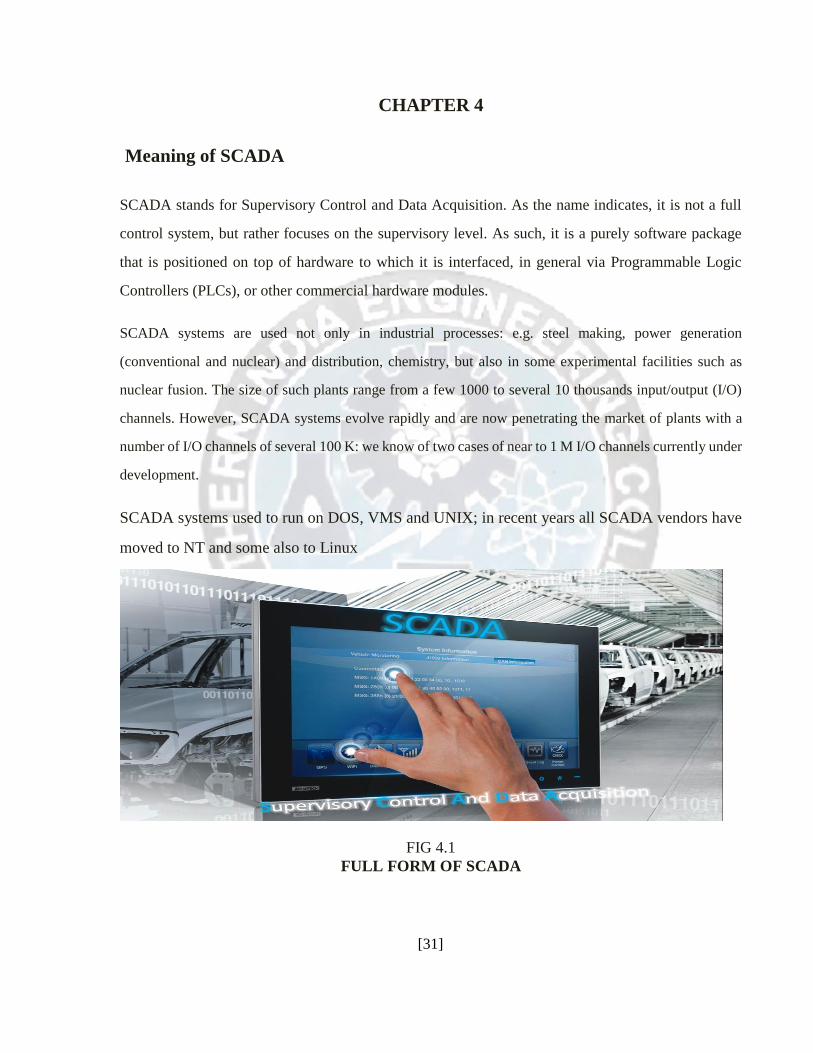
FIG 4.1
FULL FORM OF SCADA
[31]
Architecture This section describes the common features of the SCADA products that have been evaluated at CERN in
view of their possible application to the control systems of the LHC detectors [1], [2].
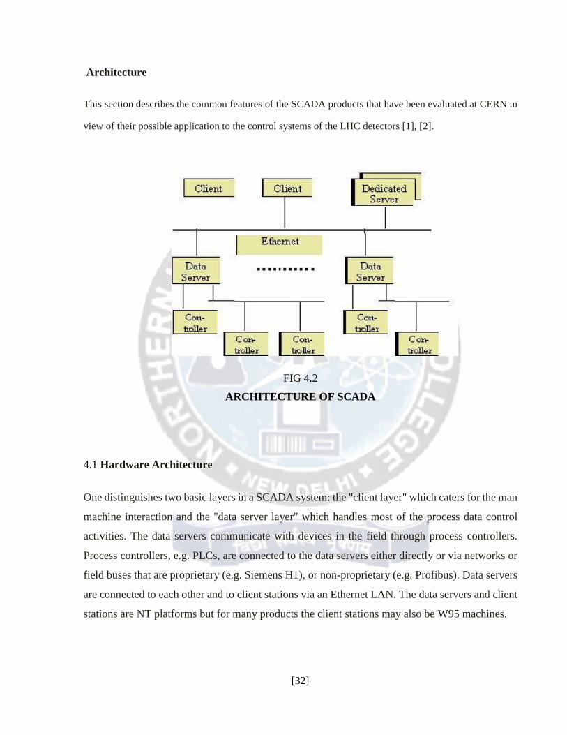
FIG 4.2
ARCHITECTURE OF SCADA
4.1 Hardware Architecture One distinguishes two basic layers in a SCADA system: the "client layer" which caters for the man
machine interaction and the "data server layer" which handles most of the process data control
activities. The data servers communicate with devices in the field through process controllers.
Process controllers, e.g. PLCs, are connected to the data servers either directly or via networks or
field buses that are proprietary (e.g. Siemens H1), or non-proprietary (e.g. Profibus). Data servers
are connected to each other and to client stations via an Ethernet LAN. The data servers and client
stations are NT platforms but for many products the client stations may also be W95 machines.
[32]

4.2 Communications 4.2.1 Internal Communication Server-client and server-server communication is in general on a publish-subscribe and event-
driven basis and uses a TCP/IP protocol, i.e., a client application subscribes to a parameter which
is owned by a particular server application and only changes to that parameter are then
communicated to the client application.
4.2.2 Access to Devices The data servers poll the controllers at a user defined polling rate. The polling rate may be different for
different parameters. The controllers pass the requested parameters to the data servers. Time stamping
of the process parameters is typically performed in the controllers and this time-stamp is taken over by
the data server. If the controller and communication protocol used support unsolicited data transfer
then the products will support this too.
The products provide communication drivers for most of the common PLCs and widely used field-
buses, e.g., Modbus. Of the three fieldbuses that are recommended at CERN, both Profibus and
World flip are supported but CANbus often not [3]. Some of the drivers are based on third party
products (e.g., Applicom cards) and therefore have additional cost associated with them. VME on
the other hand is generally not supported.
A single data server can support multiple communications protocols: it can generally support as
many such protocols as it has slots for interface cards.
The effort required to develop new drivers is typically in the range of 2-6 weeks depending on the
complexity and similarity with existing drivers, and a driver development toolkit is provided for
this.
[33]
4.2.3 Interfacing The provision of OPC client functionality for SCADA to access devices in an open and standard
manner is developing. There still seems to be a lack of devices/controllers, which provide OPC
server software, but this improves rapidly as most of the producers of controllers are actively
involved in the development of this standard. OPC has been evaluated by the CERN-IT-CO group.
The products also provide
An Open Data Base Connectivity (ODBC) interface to the data in the archive/logs, but
not to the configuration database,
An ASCII import/export facility for configuration data,
A library of APIs supporting C, C++, and Visual Basic (VB) to access data in the
RTDB, logs and archive. The API often does not provide access to the product's internal
features such as alarm handling, reporting, trending, etc.
The PC products provide support for the Microsoft standards such as Dynamic Data Exchange
(DDE) which allows e.g. to visualize data dynamically in an EXCEL spreadsheet, Dynamic Link
Library (DLL) and Object Linking and Embedding (OLE).
The configuration data are stored in a database that is logically centralized but physically
distributed and that is generally of a proprietary format.
For performance reasons, the RTDB resides in the memory of the servers and is also of proprietary
format.
The archive and logging format is usually also proprietary for performance reasons, but some
products do support logging to a Relational Data Base Management System (RDBMS) at a slower
rate either directly or via an ODBC interface.
[34]
4.2.4 Scalability Scalability is understood as the possibility to extend the SCADA based control system by adding
more process variables, more specialized servers (e.g. for alarm handling) or more clients. The
products achieve scalability by having multiple data servers connected to multiple controllers.
Each data server has its own configuration database and RTDB and is responsible for the handling
of a sub-set of the process variables (acquisition, alarm handling, archiving).
4.2.5 Redundancy The products often have built in software redundancy at a server level, which is normally
transparent to the user. Many of the products also provide more complete redundancy solutions if
required.
4.3 Functionality 4.3.1 Access Control Users are allocated to groups, which have defined read/write access privileges to the process
parameters in the system and often also to specific product functionality.
4.3.2 MMI The products support multiple screens, which can contain combinations of synoptic diagrams and
text.
They also support the concept of a "generic" graphical object with links to process variables. These
objects can be "dragged and dropped" from a library and included into a synoptic diagram.
[35]

be applicable to the type of applications encountered in the experimental physics community.
Standard windows editing facilities are provided: zooming, re-sizing, scrolling... On-line
configuration and customization of the MMI is possible for users with the appropriate privileges.
Links can be created between display pages to navigate from one view to another.
4.3.3 Trending The products all provide trending facilities and one can summarize the common capabilities as
follows:
The parameters to be trended in a specific chart can be predefined or defined on-line
A chart may contain more than 8 trended parameters or pens and an unlimited number
of charts can be displayed (restricted only by the readability)
Real-time and historical trending are possible, although generally not in the same chart
4.4 Alarm Handling Alarm handling is based on limit and status checking and performed in the data servers. More
complicated expressions (using arithmetic or logical expressions) can be developed by creating
derived parameters on which status or limit checking is then performed. The alarms are logically
handled centrally, i.e., the information only exists in one place and all users see the same status
(e.g., the acknowledgement), and multiple alarm priority levels (in general many more than 3 such
levels) are supported.
It is generally possible to group alarms and to handle these as an entity (typically filtering on group
or acknowledgement of all alarms in a group). Furthermore, it is possible to suppress alarms either
individually or as a complete group. The filtering of alarms seen on the alarm page or when
viewing the alarm log is also possible at least on priority, time and group. However, relationships
between alarms cannot generally be defined in a straightforward manner. E-mails can be generated
or predefined actions automatically executed in response to alarm conditions.
[36]
4.5 Logging/Archiving The terms logging and archiving are often used to describe the same facility. However, logging
can be thought of as medium-term storage of data on disk, whereas archiving is long-term storage
of data either on disk or on another permanent storage medium. Logging is typically performed on
a cyclic basis, i.e., once a certain file size, time period or number of points is reached the data is
overwritten. Logging of data can be performed at a set frequency, or only initiated if the value
changes or when a specific predefined event occurs. Logged data can be transferred to an archive
once the log is full. The logged data is time-stamped and can be filtered when viewed by a user.
The logging of user actions is in general performed together with either a user ID or station ID.
There is often also a VCR facility to play back archived data.
4.6 Report Generation One can produce reports using SQL type queries to the archive, RTDB or logs. Although it is
sometimes possible to embed EXCEL charts in the report, a "cut and paste" capability is in general
not provided. Facilities exist to be able to automatically generate, print and archive reports.
4.7 Automation The majority of the products allow actions to be automatically triggered by events. A scripting
language provided by the SCADA products allows these actions to be defined. In general, one can
load a particular display, send an Email, run a user defined application or script and write to the
RTDB.
The concept of recipes is supported, whereby a particular system configuration can be saved to a
file and then re-loaded at a later date.
[37]
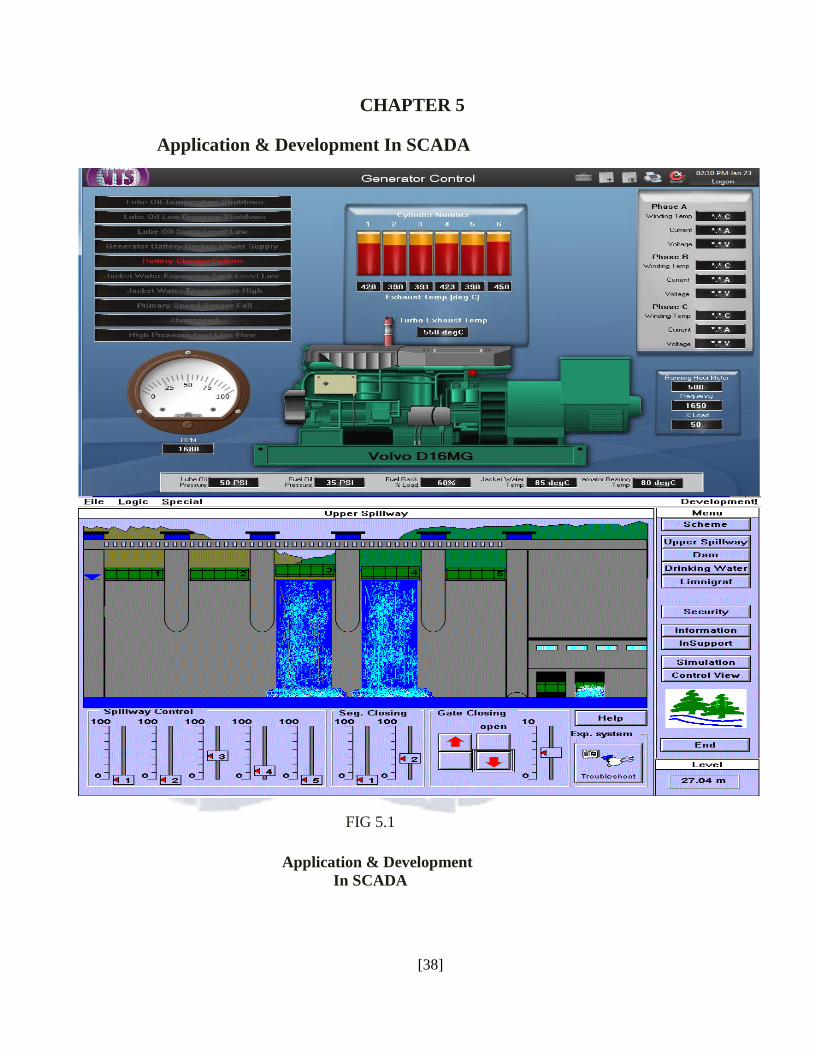
CHAPTER 5
Application & Development In SCADA
FIG 5.1
Application & Development
In SCADA [38]
5.1 Configuration The development of the applications is typically done in two stages. First the process parameters
and associated information (e.g. relating to alarm conditions) are defined through some sort of
parameter definition template and then the graphics, including trending and alarm displays are
developed, and linked where appropriate to the process parameters. The products also provide an
ASCII Export/Import facility for the configuration data (parameter definitions), which enables
large numbers of parameters to be configured in a more efficient manner using an external editor
such as Excel and then importing the data into the configuration database.
However, many of the PC tools now have a Windows Explorer type development studio. The
developer then works with a number of folders, which each contains a different aspect of the
configuration, including the graphics.
The facilities provided by the products for configuring very large numbers of parameters are not
very strong. However, this has not really been an issue so far for most of the products to-date, as
large applications are typically about 50K I/O points and database population from within an
ASCII editor such as Excel is still a workable option.
On-line modifications to the configuration database and the graphics are generally possible with
the appropriate level of privileges.
[39]
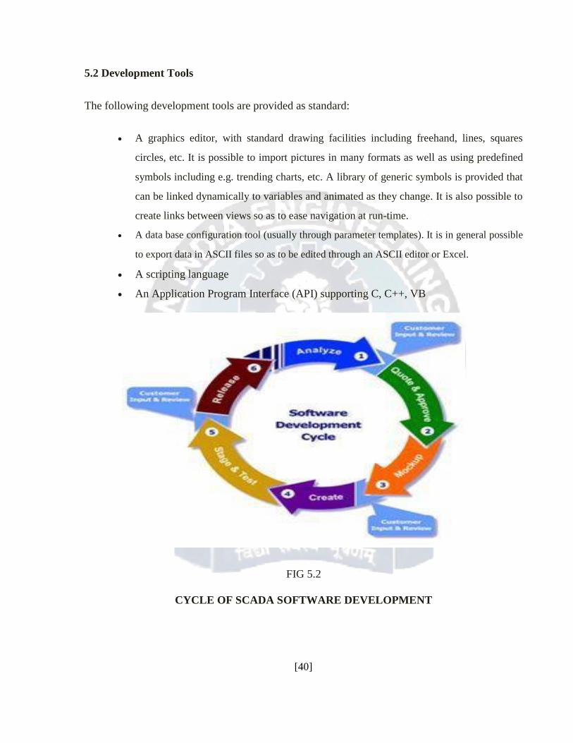
5.2 Development Tools The following development tools are provided as standard:
A graphics editor, with standard drawing facilities including freehand, lines, squares
circles, etc. It is possible to import pictures in many formats as well as using predefined
symbols including e.g. trending charts, etc. A library of generic symbols is provided that
can be linked dynamically to variables and animated as they change. It is also possible to
create links between views so as to ease navigation at run-time.
A data base configuration tool (usually through parameter templates). It is in general possible
to export data in ASCII files so as to be edited through an ASCII editor or Excel.
A scripting language
An Application Program Interface (API) supporting C, C++, VB
FIG 5.2
CYCLE OF SCADA SOFTWARE DEVELOPMENT
[40]
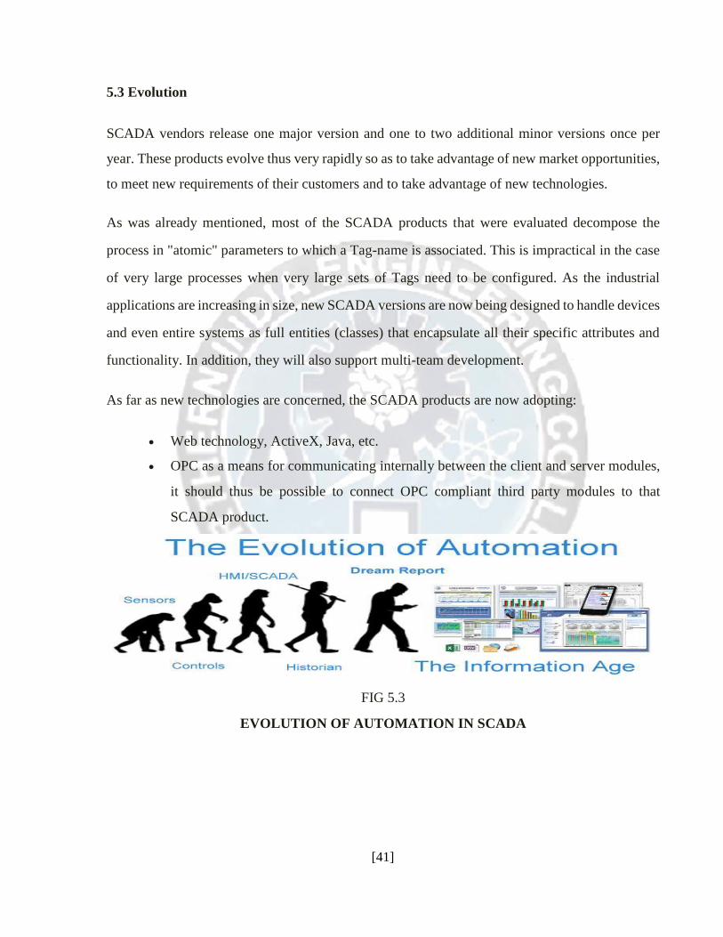
5.3 Evolution SCADA vendors release one major version and one to two additional minor versions once per
year. These products evolve thus very rapidly so as to take advantage of new market opportunities,
to meet new requirements of their customers and to take advantage of new technologies.
As was already mentioned, most of the SCADA products that were evaluated decompose the
process in "atomic" parameters to which a Tag-name is associated. This is impractical in the case
of very large processes when very large sets of Tags need to be configured. As the industrial
applications are increasing in size, new SCADA versions are now being designed to handle devices
and even entire systems as full entities (classes) that encapsulate all their specific attributes and
functionality. In addition, they will also support multi-team development.
As far as new technologies are concerned, the SCADA products are now adopting:
Web technology, ActiveX, Java, etc.
OPC as a means for communicating internally between the client and server modules,
it should thus be possible to connect OPC compliant third party modules to that
SCADA product.
FIG 5.3
EVOLUTION OF AUTOMATION IN SCADA
[41]
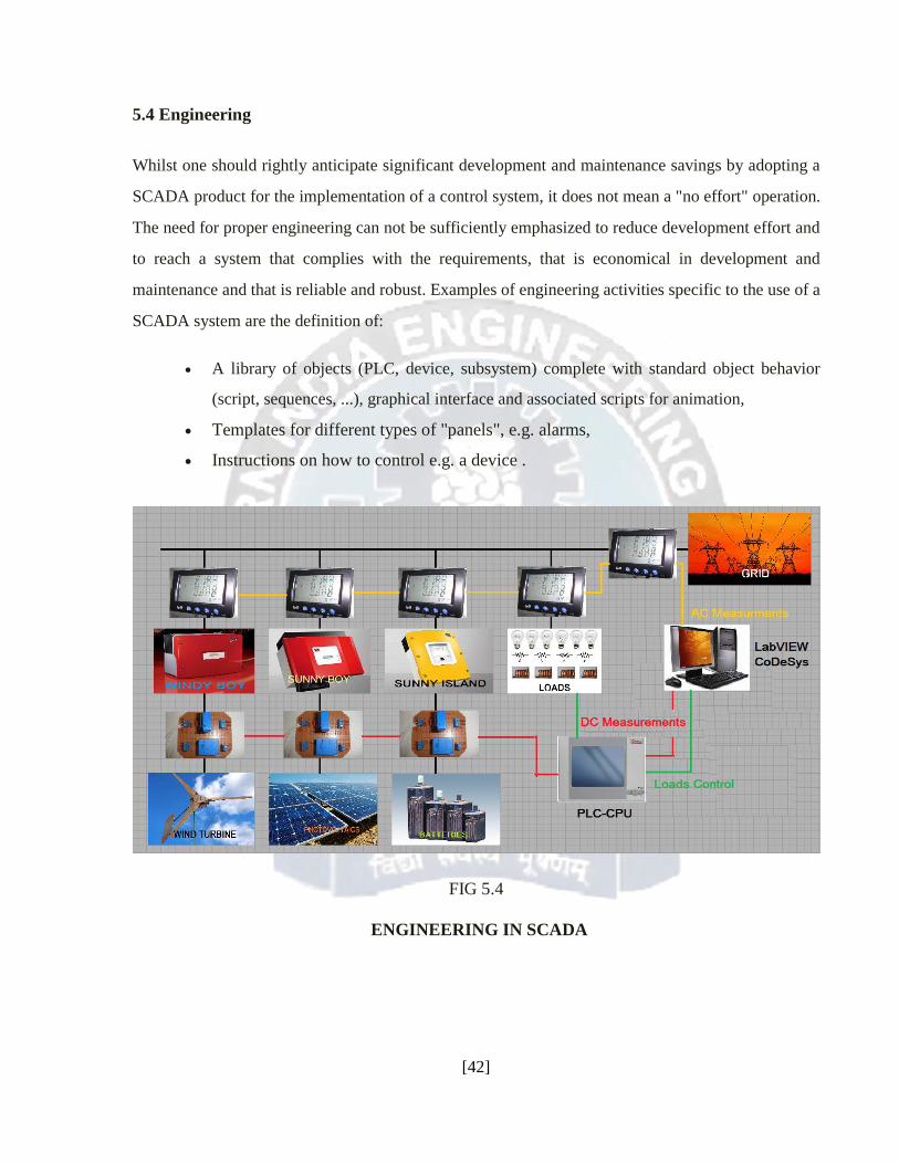
5.4 Engineering Whilst one should rightly anticipate significant development and maintenance savings by adopting a
SCADA product for the implementation of a control system, it does not mean a "no effort" operation.
The need for proper engineering can not be sufficiently emphasized to reduce development effort and
to reach a system that complies with the requirements, that is economical in development and
maintenance and that is reliable and robust. Examples of engineering activities specific to the use of a
SCADA system are the definition of:
A library of objects (PLC, device, subsystem) complete with standard object behavior
(script, sequences, ...), graphical interface and associated scripts for animation,
Templates for different types of "panels", e.g. alarms,
Instructions on how to control e.g. a device .
FIG 5.4
ENGINEERING IN SCADA
[42]
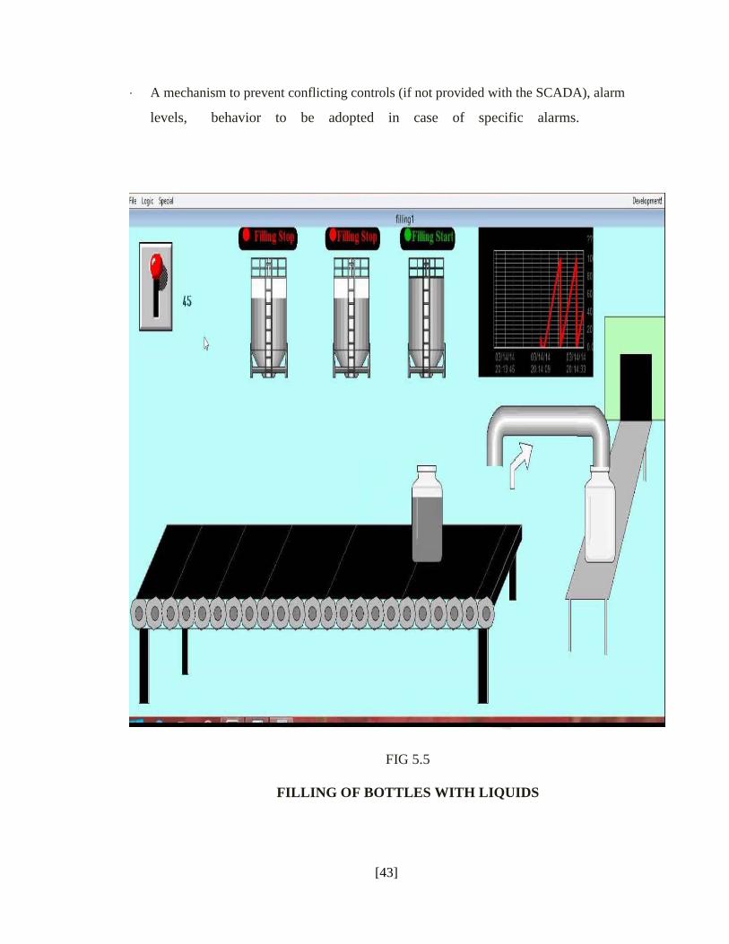
· A mechanism to prevent conflicting controls (if not provided with the SCADA), alarm
levels, behavior to be adopted in case of specific alarms.
FIG 5.5
FILLING OF BOTTLES WITH LIQUIDS
[43]
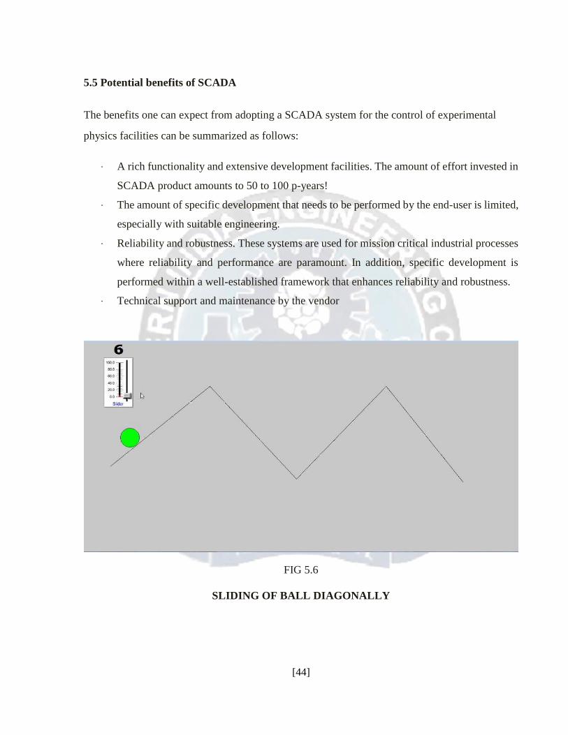
5.5 Potential benefits of SCADA The benefits one can expect from adopting a SCADA system for the control of experimental
physics facilities can be summarized as follows:
· A rich functionality and extensive development facilities. The amount of effort invested in
SCADA product amounts to 50 to 100 p-years!
· The amount of specific development that needs to be performed by the end-user is limited,
especially with suitable engineering.
· Reliability and robustness. These systems are used for mission critical industrial processes
where reliability and performance are paramount. In addition, specific development is
performed within a well-established framework that enhances reliability and robustness.
· Technical support and maintenance by the vendor
FIG 5.6
SLIDING OF BALL DIAGONALLY
[44]
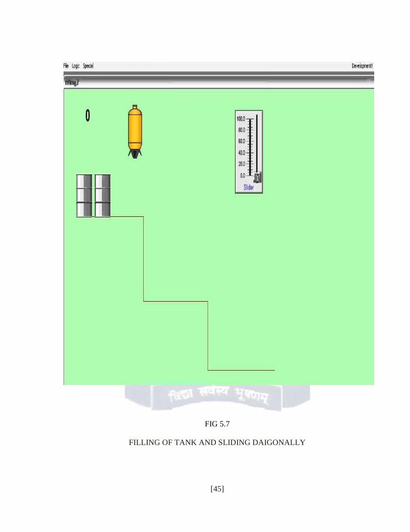
FIG 5.7
FILLING OF TANK AND SLIDING DAIGONALLY
[45]

REFERENCES [1] A.Daneels, W.Salter, "Technology Survey Summary of Study Report", IT-CO/98-08-
09, CERN, Geneva 26th Aug 1998.
[2] A.Daneels, W.Salter, "Selection and Evaluation of Commercial SCADA Systems for
the Controls of the CERN LHC Experiments", Proceedings of the 1999 International
Conference on Accelerator and Large Experimental Physics Control Systems, Trieste,
1999, p.353.
[3] G.Baribaud et al., "Recommendations for the Use of Fieldbuses at CERN in the LHC
Era", Proceedings of the 1997 International Conference on Accelerator and Large
Experimental Physics Control Systems, Beijing, 1997, p.285.
[4] R.Barillere et al., "Results of the OPC Evaluation done within the JCOP for the Control
of the LHC Experiments", Proceedings of the 1999 International Conference on
Accelerator and Large Experimental Physics Control Systems, Trieste, 1999, p.511.
[46]
CONCLUSION
PLC and SCADA is used for the constructive working not for the destructive work using a PLC
and SCADA system for their controls ensures a common framework not only for the development
of the specific applications but also for operating the detectors. Operators experience the same
"look and feel" whatever part of the experiment they control. However, this aspect also depends
to a significant extent on proper engineering.
[47]
Related Documents


![For The Region: Report, Report, Report [Eng]](https://static.cupdf.com/doc/110x72/579079761a28ab6874c751c6/for-the-region-report-report-report-eng.jpg)