ICCPGE 2016, 1, 201 - 209 Study of Mass Transfer Coefficient in a Wetted Wall Column 1,* Abdualnaser M. Almagrbi Moammer M. Elzwail 1 , Walid A. Alaswad 1 , Saleh O. Handi 2 1 Chemical and Petroleum Engineering Department, Al-Mergib University, Alkhoms, Libya 2 Chemical Engineering Department, High Institute for Comperhensive Professions, Alkhoms, Libya * Corresponding Author: [email protected] Abstract Gas absorption is the unit operation in which one or more soluble components of gas mixture are dissolved in a liquid. The absorption may be a purely physical phenomenon or may involve chemical reaction with one or more constituents in the liquid solution. In order to obtain the highest rate of absorption, gas and liquid streams flow in opposite directions in counter-current flow. The unit in this work has been designed to help grasp the basic principles of the chemical and physical aspects involved in absorption. This study unit is made of borosilicate transparent glass in order to show the water spread in the column and get the visual distribution of fluids behavior which helps to fully understand the phenomenon. In the spray wetted wall columns, an efficient contact between the phases is achieved by atomizing through fixed or rotary nozzles. The nozzles are arranged along the periphery and the fluids are fed in a counter-current flow. This obstruction-free operation makes this type of process suitable to treat flow rate containing a great number of solid particles. In this work, the wetted wall column is used to determine gas/liquid mass transfer coefficients, which is essential to design absorption towers. This study investigates the absorption of oxygen from air into deoxygenated water (prepared by nitrogen sparging) in liquid film- controlled absorption experiment. The liquid film mass transfer coefficient is calculated at various mass flow rates of water and air. This work also studies the effect of water flow and air flow on oxygen concentration in the oxygenation and de-oxygenation process. Keywords: Absorption; wetted wall; mass transfer coefficient; oxygenation; deoxygenation. 1. Introduction The removal of one or more selected components from a mixture of gases by absorption into a suit- able liquid is the second major operation of chem- ical engineering that is based on interphase mass transfer controlled largely by rates of diffusion. The gas-liquid absorption process may be treated as a physical process; the chemical reaction doesn’t hold considerable effect. However when nitrogen oxides are absorbed in water to produce nitric acid, or when carbon dioxide is absorbed in a solution of sodium hydroxide, a chemical reaction occurs, which effects the actual rate of absorption. Absorption processes are therefore conveniently divided into two groups, those in which the process is solely physical and those where a chemical reaction is af- fecting the process. In considering the design of equipment to achieve gas absorption, the main re- quirement is that the gas should be brought into intimate contact with the liquid, and the effecting of the equipment will mainly be determined by the contact degree reached between the two phases. In absorption, usually the gas is fed at the bottom of the column, and the solvent is fed at the top. The solvent and absorbed gas leave at the bottom, and the unabsorbed components leave as gas from the top. The essential difference between distillation and absorption is that in the former the vapour has to be produced in each stage by partial vaporization of the liquid at its boiling point, whereas in absorp- tion the liquid is well below its boiling point. In distillation there is a diffusion of molecules in both 201 ,

Welcome message from author
This document is posted to help you gain knowledge. Please leave a comment to let me know what you think about it! Share it to your friends and learn new things together.
Transcript
ICCPGE 2016, 1, 201 - 209
Study of Mass Transfer Coefficient in a Wetted Wall Column
1,* Abdualnaser M. Almagrbi Moammer M. Elzwail1, Walid A. Alaswad1, Saleh O. Handi2
1Chemical and Petroleum Engineering Department, Al-Mergib University, Alkhoms, Libya2Chemical Engineering Department, High Institute for Comperhensive Professions, Alkhoms, Libya
*Corresponding Author: [email protected]
Abstract
Gas absorption is the unit operation in which one or more soluble components of gas mixture are dissolvedin a liquid. The absorption may be a purely physical phenomenon or may involve chemical reaction withone or more constituents in the liquid solution. In order to obtain the highest rate of absorption, gas andliquid streams flow in opposite directions in counter-current flow. The unit in this work has been designedto help grasp the basic principles of the chemical and physical aspects involved in absorption. This studyunit is made of borosilicate transparent glass in order to show the water spread in the column and getthe visual distribution of fluids behavior which helps to fully understand the phenomenon. In the spraywetted wall columns, an efficient contact between the phases is achieved by atomizing through fixed orrotary nozzles. The nozzles are arranged along the periphery and the fluids are fed in a counter-currentflow. This obstruction-free operation makes this type of process suitable to treat flow rate containinga great number of solid particles. In this work, the wetted wall column is used to determine gas/liquidmass transfer coefficients, which is essential to design absorption towers. This study investigates theabsorption of oxygen from air into deoxygenated water (prepared by nitrogen sparging) in liquid film-controlled absorption experiment. The liquid film mass transfer coefficient is calculated at various massflow rates of water and air. This work also studies the effect of water flow and air flow on oxygenconcentration in the oxygenation and de-oxygenation process.
Keywords: Absorption; wetted wall; mass transfer coefficient; oxygenation; deoxygenation.
1. Introduction
The removal of one or more selected componentsfrom a mixture of gases by absorption into a suit-able liquid is the second major operation of chem-ical engineering that is based on interphase masstransfer controlled largely by rates of diffusion. Thegas-liquid absorption process may be treated as aphysical process; the chemical reaction doesn’t holdconsiderable effect. However when nitrogen oxidesare absorbed in water to produce nitric acid, orwhen carbon dioxide is absorbed in a solution ofsodium hydroxide, a chemical reaction occurs, whicheffects the actual rate of absorption. Absorptionprocesses are therefore conveniently divided intotwo groups, those in which the process is solelyphysical and those where a chemical reaction is af-
fecting the process. In considering the design ofequipment to achieve gas absorption, the main re-quirement is that the gas should be brought intointimate contact with the liquid, and the effectingof the equipment will mainly be determined by thecontact degree reached between the two phases. Inabsorption, usually the gas is fed at the bottom ofthe column, and the solvent is fed at the top. Thesolvent and absorbed gas leave at the bottom, andthe unabsorbed components leave as gas from thetop. The essential difference between distillationand absorption is that in the former the vapour hasto be produced in each stage by partial vaporizationof the liquid at its boiling point, whereas in absorp-tion the liquid is well below its boiling point. Indistillation there is a diffusion of molecules in both
201
,
directions, so that for an ideal system equimolecularcounter diffusion takes place, though in absorptiongas molecules are diffusing into the liquid, with neg-ligible transfer in the reverse direction, in general,the ratio of the liquid to the gas flow rate is con-siderably greater in absorption than in distillationwith the result that layout of the trays is differentin the two cases [1].
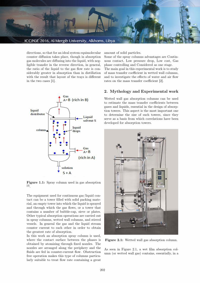
Figure 1.1: Spray column used in gas absorption[2].
The equipment used for continuous gas/liquid con-tact can be a tower filled with solid packing mate-rial, an empty tower into which the liquid is sprayedand through which the gas flows, or a tower thatcontains a number of bubble-cap, sieve or plates.Other typical absorption operations are carried outin spray columns, wetted wall columns, and stirredvessels. In general the gas and the liquid streamcounter current to each other in order to obtainthe greatest rate of absorption.In this work an absorption spray column is used,where the contact surface between the phases isobtained by atomizing through fixed nozzles. Thenozzles are arranged along the periphery and thefluids are fed in counter-current flow. Obstructionfree operation makes this type of columns particu-larly suitable to treat flow rate containing a great
amount of solid particles.Some of the spray columns advantages are Contin-uous contact, Low pressure drop, Low cost, Gasphase controlling and Considered as one stage.The main goal in this experimental work is to studyof mass transfer coefficient in wetted wall columns,and to investigate the effects of water and air flowrates on the mass transfer coefficient [2].
2. Mythology and Experimental work
Wetted wall gas absorption columns can be usedto estimate the mass transfer coefficients betweengases and liquids, essential in the design of absorp-tion towers. This aspect is the most important oneto determine the size of such towers, since theyserve as a basis from which correlations have beendeveloped for absorption towers.
Figure 2.1: Wetted wall gas absorption column.
As seen in Figure 2.1, a wet film absorption col-umn (or wetted wall gas) contains, essentially, in a
202
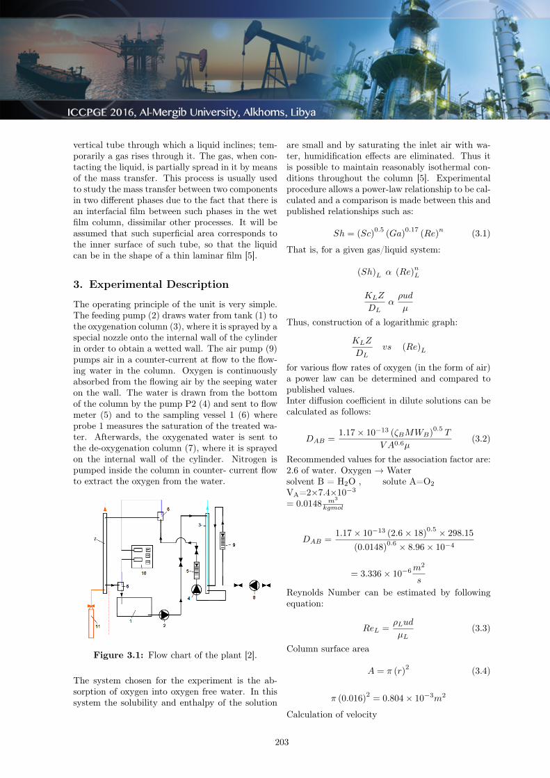
vertical tube through which a liquid inclines; tem-porarily a gas rises through it. The gas, when con-tacting the liquid, is partially spread in it by meansof the mass transfer. This process is usually usedto study the mass transfer between two componentsin two different phases due to the fact that there isan interfacial film between such phases in the wetfilm column, dissimilar other processes. It will beassumed that such superficial area corresponds tothe inner surface of such tube, so that the liquidcan be in the shape of a thin laminar film [5].
3. Experimental Description
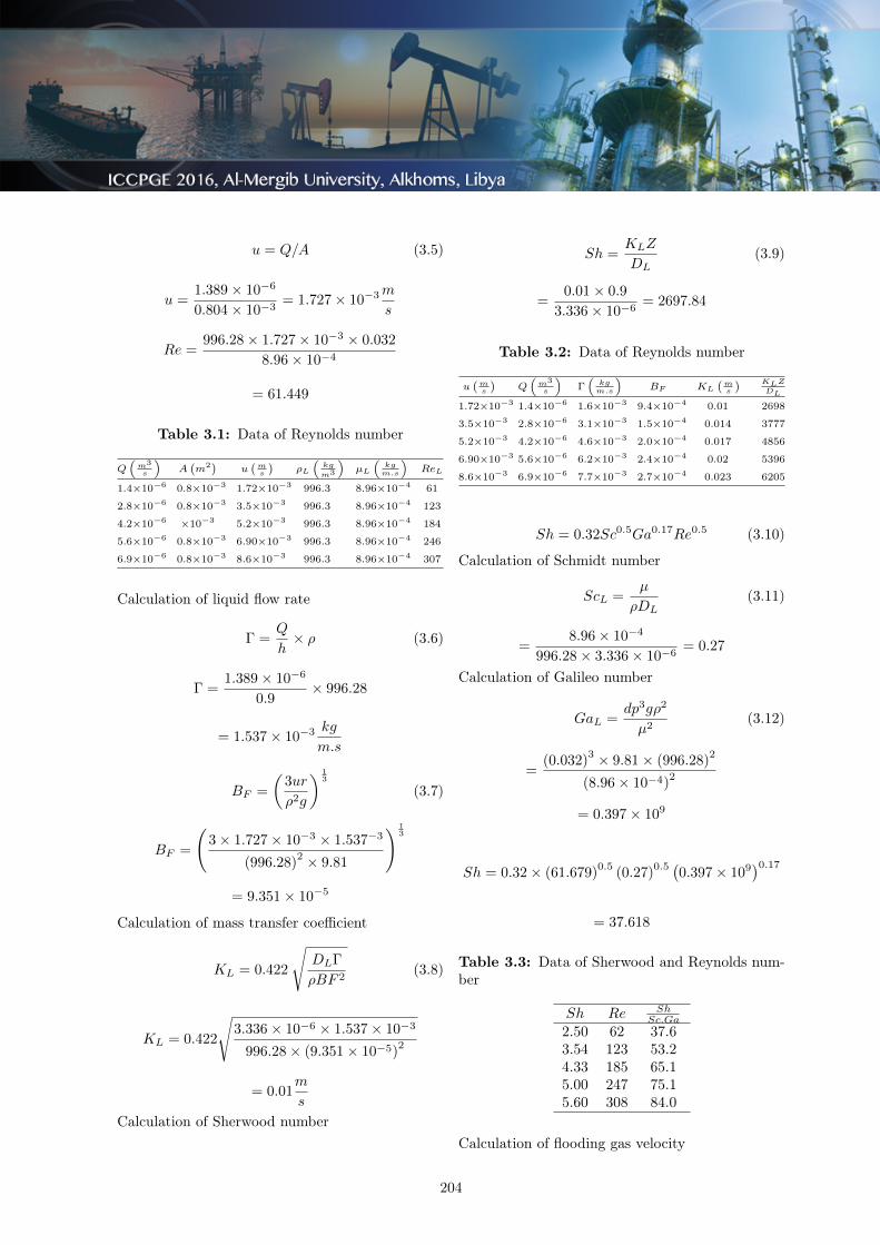
The operating principle of the unit is very simple.The feeding pump (2) draws water from tank (1) tothe oxygenation column (3), where it is sprayed by aspecial nozzle onto the internal wall of the cylinderin order to obtain a wetted wall. The air pump (9)pumps air in a counter-current at flow to the flow-ing water in the column. Oxygen is continuouslyabsorbed from the flowing air by the seeping wateron the wall. The water is drawn from the bottomof the column by the pump P2 (4) and sent to flowmeter (5) and to the sampling vessel 1 (6) whereprobe 1 measures the saturation of the treated wa-ter. Afterwards, the oxygenated water is sent tothe de-oxygenation column (7), where it is sprayedon the internal wall of the cylinder. Nitrogen ispumped inside the column in counter- current flowto extract the oxygen from the water.
Figure 3.1: Flow chart of the plant [2].
The system chosen for the experiment is the ab-sorption of oxygen into oxygen free water. In thissystem the solubility and enthalpy of the solution
are small and by saturating the inlet air with wa-ter, humidification effects are eliminated. Thus itis possible to maintain reasonably isothermal con-ditions throughout the column [5]. Experimentalprocedure allows a power-law relationship to be cal-culated and a comparison is made between this andpublished relationships such as:
Sh = (Sc)0.5
(Ga)0.17
(Re)n (3.1)
That is, for a given gas/liquid system:
(Sh)L α (Re)nL
KLZ
DLαρud
µ
Thus, construction of a logarithmic graph:
KLZ
DLvs (Re)L
for various flow rates of oxygen (in the form of air)a power law can be determined and compared topublished values.Inter diffusion coefficient in dilute solutions can becalculated as follows:
DAB =1.17 × 10⁻¹³ (ζBMWB)
0.5T
V A0.6µ(3.2)
Recommended values for the association factor are:2.6 of water. Oxygen → Watersolvent B = H2O , solute A=O2VA=2×7.4×10−3
= 0.0148 m3
kgmol
DAB =1.17 × 10⁻¹³ (2.6 × 18)
0.5 × 298.15
(0.0148)0.6 × 8.96 × 10−4
= 3.336 × 10⁻⁶m2
s
Reynolds Number can be estimated by followingequation:
ReL =ρLud
µL(3.3)
Column surface area
A = π (r)2 (3.4)
π (0.016)2
= 0.804 × 10⁻³m2
Calculation of velocity
203
u = Q/A (3.5)
u =1.389 × 10⁻⁶
0.804 × 10−3= 1.727 × 10⁻³m
s
Re =996.28 × 1.727 × 10−3 × 0.032
8.96 × 10−4
= 61.449
Table 3.1: Data of Reynolds number
Q(
m3
s
)A
(m2
)u(ms
)ρL
(kg
m3
)µL
(kgm.s
)ReL
1.4×10⁻⁶ 0.8×10⁻³ 1.72×10⁻³ 996.3 8.96×10⁻⁴ 61
2.8×10⁻⁶ 0.8×10⁻³ 3.5×10⁻³ 996.3 8.96×10⁻⁴ 123
4.2×10−6 ×10−3 5.2×10⁻³ 996.3 8.96×10⁻⁴ 184
5.6×10⁻⁶ 0.8×10⁻³ 6.90×10⁻³ 996.3 8.96×10⁻⁴ 246
6.9×10⁻⁶ 0.8×10⁻³ 8.6×10⁻³ 996.3 8.96×10⁻⁴ 307
Calculation of liquid flow rate
Γ =Q
h× ρ (3.6)
Γ =1.389 × 10⁻⁶
0.9× 996.28
= 1.537 × 10⁻³ kg
m.s
BF =
(3ur
ρ2g
) 13
(3.7)
BF =
(3 × 1.727 × 10−3 × 1.537−3
(996.28)2 × 9.81
) 13
= 9.351 × 10⁻⁵
Calculation of mass transfer coefficient
KL = 0.422
√DLΓ
ρBF 2(3.8)
KL = 0.422
√3.336 × 10−6 × 1.537 × 10−3
996.28 × (9.351 × 10−5)2
= 0.01m
s
Calculation of Sherwood number
Sh =KLZ
DL(3.9)
=0.01 × 0.9
3.336 × 10−6= 2697.84
Table 3.2: Data of Reynolds number
u(ms
)Q
(m3
s
)Γ(
kgm.s
)BF KL
(ms
) KLZ
DL
1.72×10⁻³ 1.4×10⁻⁶ 1.6×10⁻³ 9.4×10⁻⁴ 0.01 2698
3.5×10⁻³ 2.8×10⁻⁶ 3.1×10⁻³ 1.5×10⁻⁴ 0.014 3777
5.2×10⁻³ 4.2×10⁻⁶ 4.6×10⁻³ 2.0×10⁻⁴ 0.017 4856
6.90×10⁻³ 5.6×10⁻⁶ 6.2×10⁻³ 2.4×10⁻⁴ 0.02 5396
8.6×10⁻³ 6.9×10⁻⁶ 7.7×10⁻³ 2.7×10⁻⁴ 0.023 6205
Sh = 0.32Sc0.5Ga0.17Re0.5 (3.10)
Calculation of Schmidt number
ScL =µ
ρDL(3.11)
=8.96 × 10⁻⁴
996.28 × 3.336 × 10−6= 0.27
Calculation of Galileo number
GaL =dp3gρ2
µ2(3.12)
=(0.032)
3 × 9.81 × (996.28)2
(8.96 × 10⁻⁴)2
= 0.397 × 10⁹
Sh = 0.32 × (61.679)0.5
(0.27)0.5 (
0.397 × 10⁹)0.17
= 37.618
Table 3.3: Data of Sherwood and Reynolds num-ber
Sh Re ShSc.Ga
2.50 62 37.63.54 123 53.24.33 185 65.15.00 247 75.15.60 308 84.0
Calculation of flooding gas velocity
204
Uf = F1F2
(σ
ρg
)0.5
(3.13)
The data covered column sizes up to 50-mm (2-in) diameter; the correlation should be use l withcaution for larger columns.
F2 =
(G
L
)0.25
(3.14)
L = Qρ (3.15)
L = 6.944 × 10−6 × 996.28
= 6.9 × 10⁻³ kg
s
G = Qρ (3.16)
G = 8.33 × 10−4 × 1.186
= 9.88 × 10⁻⁴ kg
s
F2 =
(9.88 × 10⁻⁴
6.918 × 10⁻³
)0.25
= 0.615
Calculation of Surface Tension
σ = A (1 − Tr)(B+CTr+DT 2
r +ET 3r ) (3.17)
A = 0.18548 , B = 2.717 , C = -3.554 , D = 2.047, E = 0
Tr =T
Tc(3.18)
=298.15
647.13= 0.46
σ = 0.185 (1 − 0.46)
(2.7+(−3.5)(0.46)+(2.04)(0.46)2+(0)(0.46)3
)
= 0.0729N
m
F1 : 1.22 when 3.2diσ> 1.0
As 3.2 0.0320.0729 = 1.404
F1=1.22
Uf = 1.22 × 0.615
(0.0729
1.186
)0.5
= 0.186m
s
4. Results and Discussion
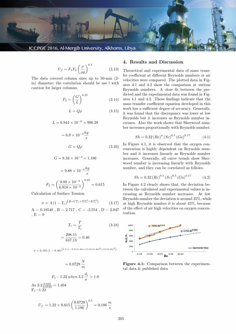
Theoretical and experimental data of mass trans-fer coefficient at different Reynolds numbers or airvelocities were compared. The plotted data in Fig-ures 4.1 and 4.2 show the comparison at variousReynolds numbers. A close fit between the pre-dicted and the experimental data was found in Fig-ures 4.1 and 4.2. These findings indicate that themass transfer coefficient equation developed in thiswork has a sufficient degree of accuracy. Generally,it was found that the discrepancy was lower at lowReynolds but it increases as Reynolds number in-creases. Also the work shows that Sherwood num-ber increases proportionally with Reynolds number.
Sh = 0.32 (Re)n
(Sc)0.5
(Ga)0.17 (4.1)
In Figure 4.1, it is observed that the oxygen con-centration is highly dependent on Reynolds num-ber and it increases linearly as Reynolds numberincreases. Generally, all curve trends show Sher-wood number is increasing linearly with Reynoldsnumber, and they can be correlated as follows:
Sh = 0.32 (Re)0.5
(Sc)0.5
(Ga)0.17 (4.2)
In Figure 4.2 clearly shows that, the deviation be-tween the calculated and experimental values is in-creasing as Reynolds number increases. At lowReynolds number the deviation is around 35%, whileat high Reynolds number it is about 45%, becauseof the effect of air high velocities on oxygen concen-tration.
Figure 4.1: Comparison between the experimen-tal data & published data
205
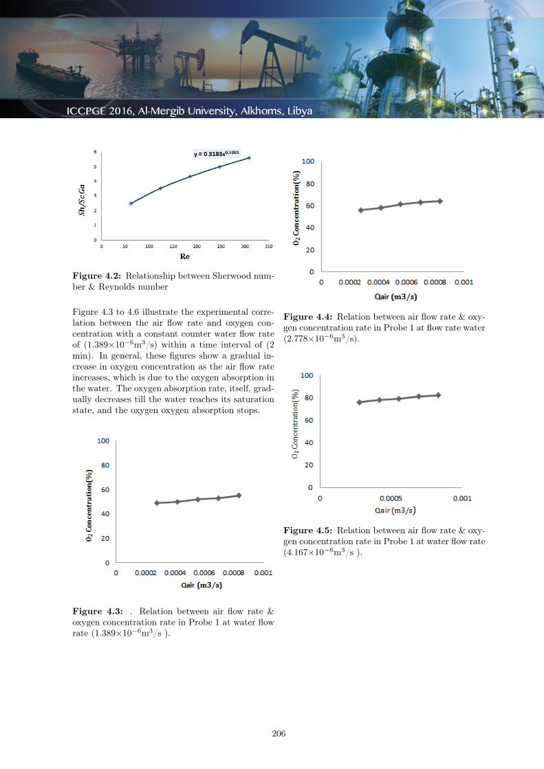
Figure 4.2: Relationship between Sherwood num-ber & Reynolds number
Figure 4.3 to 4.6 illustrate the experimental corre-lation between the air flow rate and oxygen con-centration with a constant counter water flow rateof (1.389×10⁻⁶m3/s) within a time interval of (2min). In general, these figures show a gradual in-crease in oxygen concentration as the air flow rateincreases, which is due to the oxygen absorption inthe water. The oxygen absorption rate, itself, grad-ually decreases till the water reaches its saturationstate, and the oxygen oxygen absorption stops.
Figure 4.3: . Relation between air flow rate &oxygen concentration rate in Probe 1 at water flowrate (1.389×10⁻⁶m3/s ).
Figure 4.4: Relation between air flow rate & oxy-gen concentration rate in Probe 1 at flow rate water(2.778×10⁻⁶m3/s).
Figure 4.5: Relation between air flow rate & oxy-gen concentration rate in Probe 1 at water flow rate(4.167×10⁻⁶m3/s ).
206
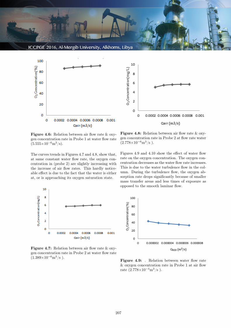
Figure 4.6: Relation between air flow rate & oxy-gen concentration rate in Probe 1 at water flow rate(5.555×10⁻⁶m3/s).
The curves trends in Figures 4.7 and 4.8, show that,at same constant water flow rate, the oxygen con-centration in (probe 2) are slightly increasing withthe increase of air flow rates. This hardly notice-able effect is due to the fact that the water is eitherat, or is approaching its oxygen saturation state.
Figure 4.7: Relation between air flow rate & oxy-gen concentration rate in Probe 2 at water flow rate(1.389×10⁻⁶m3/s ).
Figure 4.8: Relation between air flow rate & oxy-gen concentration rate in Probe 2 at flow rate water(2.778×10⁻⁶m3/s ).
Figures 4.9 and 4.10 show the effect of water flowrate on the oxygen concentration. The oxygen con-centration decreases as the water flow rate increases.This is due to the water turbulence flow in the col-umn. During the turbulence flow, the oxygen ab-sorption rate drops significantly because of smallermass transfer areas and less times of exposure asopposed to the smooth laminar flow.
Figure 4.9: . Relation between water flow rate& oxygen concentration rate in Probe 1 at air flowrate (2.778×10⁻⁴m3/s ).
207
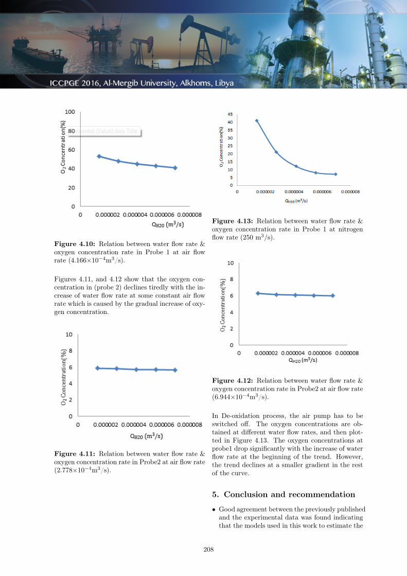
Figure 4.10: Relation between water flow rate &oxygen concentration rate in Probe 1 at air flowrate (4.166×10⁻⁴m3/s).
Figures 4.11, and 4.12 show that the oxygen con-centration in (probe 2) declines tiredly with the in-crease of water flow rate at some constant air flowrate which is caused by the gradual increase of oxy-gen concentration.
Figure 4.11: Relation between water flow rate &oxygen concentration rate in Probe2 at air flow rate(2.778×10⁻⁴m3/s).
Figure 4.13: Relation between water flow rate &oxygen concentration rate in Probe 1 at nitrogenflow rate (250 m3⁄s).
Figure 4.12: Relation between water flow rate &oxygen concentration rate in Probe2 at air flow rate(6.944×10⁻⁴m3/s).
In De-oxidation process, the air pump has to beswitched off. The oxygen concentrations are ob-tained at different water flow rates, and then plot-ted in Figure 4.13. The oxygen concentrations atprobe1 drop significantly with the increase of waterflow rate at the beginning of the trend. However,the trend declines at a smaller gradient in the restof the curve.
5. Conclusion and recommendation
• Good agreement between the previously publishedand the experimental data was found indicatingthat the models used in this work to estimate the
208
mass transfer coefficient have a sufficient degreeof accuracy.
• Some of the plotted correlations indicate that theoxygen concentration at probe2 increases slightlywith the increase of air flow rate at constant wa-ter flow.
• The oxygen concentrations at probe1 drop signif-icantly with the increase of water flow rate at thebeginning of the trend.
• Nitrogen has a significant influence as a reductionfactor to extract the oxygen from the oxygenatedwater in the de-oxidation process.
• For future studies, the temperature effect on oxy-gen concentration can be investigated in wettedwall gas absorption. In addition, graphical corre-lations of mass transfer coefficients of some othersubstances can be thoroughly studied, instead ofO2
References
[1] 1. J. R. Backhurst, J. H. Harker and J. F.Richardson; Chemical Engineering, Solutions toProblems in Volume 2, 5th Ed, 1993.
[2] 2. http:// www.didacta.it
[3] 3. Christian, H. E. Nielsen., Søren Kill, HenrikW. et al. Chem Eng Sci, 53 (3), (1998) :495-503.
[4] 4. Bird R. Stewart W. and Lightfoot E., “Trans-port Phenomena”, Wiley "2004".
[5] 5. http:// www.armfield.co.uk
[6] 6. McCabe, W. L., Smith J. C., and Harriott, P.,Unit Operations of Chemical Engineering, 6th
Ed, McGraw Hill Company, New York, 2001.
209
Related Documents