All 316 SS Construction PTFE Wetted Parts All 316 SS Construction PTFE Wetted Parts

Welcome message from author
This document is posted to help you gain knowledge. Please leave a comment to let me know what you think about it! Share it to your friends and learn new things together.
Transcript
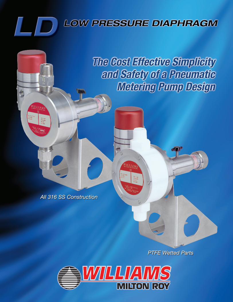
All 316 SS Construction
PTFE Wetted Parts
All 316 SS Construction
PTFE Wetted Parts
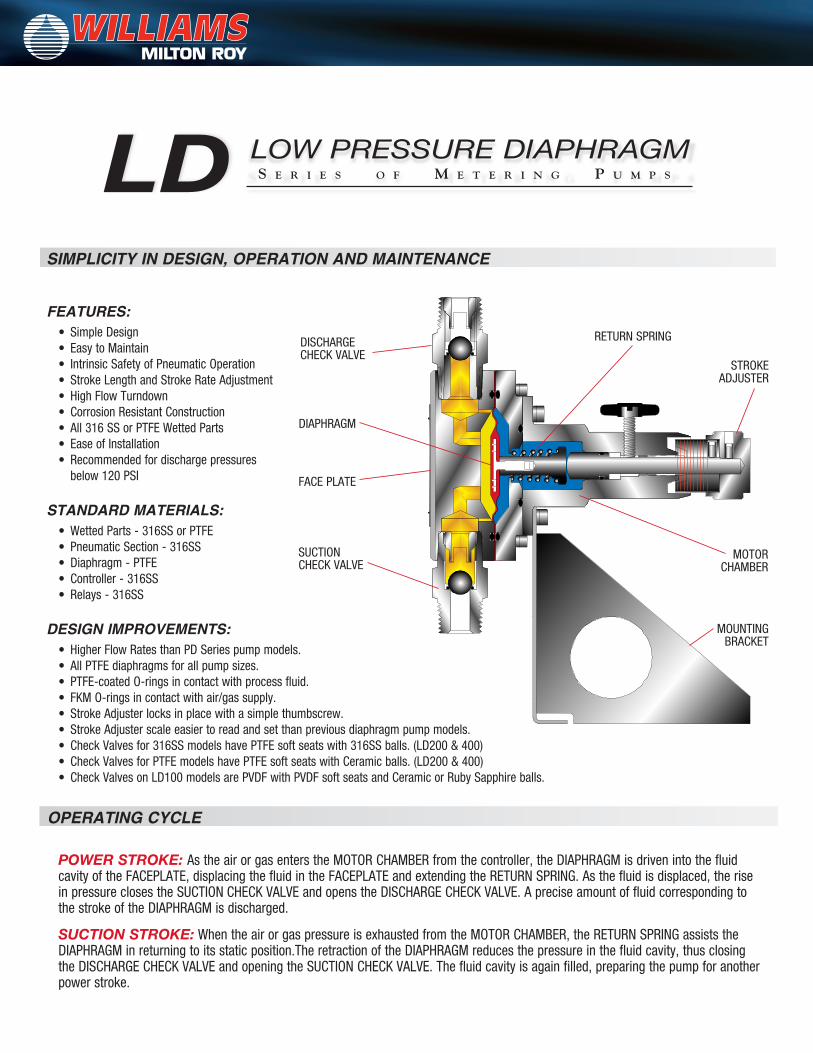
POWER STROKE: As the air or gas enters the MOTOR CHAMBER from the controller, the DIAPHRAGM is driven into the fluid cavity of the FACEPLATE, displacing the fluid in the FACEPLATE and extending the RETURN SPRING. As the fluid is displaced, the rise in pressure closes the SUCTION CHECK VALVE and opens the DISCHARGE CHECK VALVE. A precise amount of fluid corresponding to the stroke of the DIAPHRAGM is discharged.
SUCTION STROKE: When the air or gas pressure is exhausted from the MOTOR CHAMBER, the RETURN SPRING assists the DIAPHRAGM in returning to its static position.The retraction of the DIAPHRAGM reduces the pressure in the fluid cavity, thus closing the DISCHARGE CHECK VALVE and opening the SUCTION CHECK VALVE. The fluid cavity is again filled, preparing the pump for another power stroke.
OPERATING CYCLE
SIMPLICITY IN DESIGN, OPERATION AND MAINTENANCE
FEATURES: • SimpleDesign• EasytoMaintain• IntrinsicSafetyofPneumaticOperation• StrokeLengthandStrokeRateAdjustment• HighFlowTurndown• CorrosionResistantConstruction• All316SSorPTFEWettedParts• EaseofInstallation• Recommendedfordischargepressures below120PSI
STANDARD MATERIALS: • WettedParts-316SSorPTFE• PneumaticSection-316SS• Diaphragm-PTFE• Controller-316SS• Relays-316SS
DESIGN IMPROvEMENTS: • HigherFlowRatesthanPDSeriespumpmodels.• AllPTFEdiaphragmsforallpumpsizes.•PTFE-coatedO-ringsincontactwithprocessfluid.• FKMO-ringsincontactwithair/gassupply.•StrokeAdjusterlocksinplacewithasimplethumbscrew.•StrokeAdjusterscaleeasiertoreadandsetthanpreviousdiaphragmpumpmodels.• CheckValvesfor316SSmodelshavePTFEsoftseatswith316SSballs.(LD200&400)•CheckValvesforPTFEmodelshavePTFEsoftseatswithCeramicballs.(LD200&400)•CheckValvesonLD100modelsarePVDFwithPVDFsoftseatsandCeramicorRubySapphireballs.
DISCHARGE CHECK VALVE
FACE PLATE
DIAPHRAGM
SUCTIONCHECK VALVE
STROKE ADJUSTER
RETURN SPRING
MOTOR CHAMBER
MOUNTING BRACKET
S e r i e S o f M e t e r i n g P u M P S
LOW PRESSURE DIAPHRAGMLD
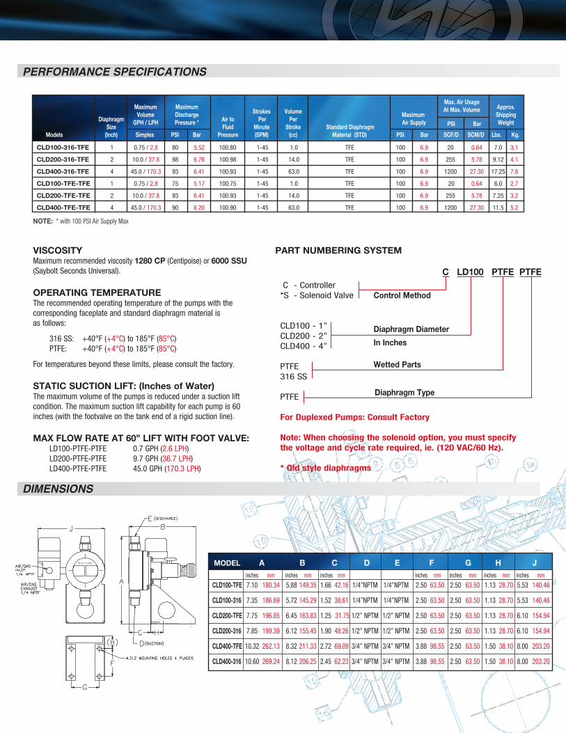
PERFORMANCE SPECIFICATIONS
DIMENSIONS
NOTE:*with100PSIAirSupplyMax
VISCOSITYMaximum recommended viscosity 1280 CP(Centipoise)or6000 SSU(SayboltSecondsUniversal).
OPERATING TEMPERATUREThe recommended operating temperature of the pumps with thecorresponding faceplate and standard diaphragm material isas follows:
316SS: +40°F(+4°C)to185°F(85°C) PTFE:+40°F(+4°C)to185°F(85°C)
For temperatures beyond these limits, please consult the factory.
STATIC SUCTION LIFT: (Inches of Water)The maximum volume of the pumps is reduced under a suction lift condition.Themaximumsuctionliftcapabilityforeachpumpis60inches(withthefootvalveonthetankendofarigidsuctionline).
MAx FLOW RATE AT 60” LIFT WITh FOOT VALVE: LD100-PTFE-PTFE 0.7GPH(2.6LPH) LD200-PTFE-PTFE 9.7GPH(36.7LPH) LD400-PTFE-PTFE 45.0GPH(170.3LPH)
PART NUMBERING SYSTEM
C LD100 PTFE PTFE
C -Controller*S -SolenoidValve Control Method
CLD100-1” Diaphragm DiameterCLD200-2”CLD400-4” In Inches
PTFE Wetted Parts316SS
PTFE Diaphragm Type
For Duplexed Pumps: Consult Factory
Note: When choosing the solenoid option, you must specify the voltage and cycle rate required, ie. (120 VAC/60 Hz).
* Old style diaphragms
CLD100-316-TFE 1 0.75/2.8 80 5.52 100.80 1-45 1.0 TFE 100 6.9 20 0.64 7.0 3.1
CLD200-316-TFE 2 10.0/37.8 98 6.76 100.98 1-45 14.0 TFE 100 6.9 255 5.78 9.12 4.1
CLD400-316-TFE 4 45.0/170.3 93 6.41 100.93 1-45 63.0 TFE 100 6.9 1200 27.3017.25 7.8
CLD100-TFE-TFE 1 0.75/2.8 75 5.17 100.75 1-45 1.0 TFE 100 6.9 20 0.64 6.0 2.7
CLD200-TFE-TFE 2 10.0/37.8 93 6.41 100.93 1-45 14.0 TFE 100 6.9 255 5.78 7.253.2
CLD400-TFE-TFE 4 45.0/170.3 90 6.20 100.90 1-45 63.0 TFE 100 6.9 1200 27.3011.5 5.2
W I L L I A M S MODEL A B C D E F G h J inches mm inches mm inches mm inches mm inches mm inches mm inches mm
CLD100-TFE 7.10 180.34 5.88149.35 1.66 42.16 1/4”NPTM 1/4”NPTM 2.50 63.50 2.50 63.50 1.13 28.70 5.53 140.46
CLD100-316 7.35 186.69 5.72145.29 1.52 38.61 1/4”NPTM 1/4”NPTM 2.50 63.50 2.50 63.50 1.13 28.70 5.53 140.46
CLD200-TFE 7.75 196.85 6.45163.83 1.25 31.751/2”NPTM 1/2”NPTM 2.50 63.50 2.50 63.50 1.13 28.70 6.10 154.94
CLD200-316 7.85 199.39 6.12155.45 1.90 48.26 1/2”NPTM 1/2”NPTM 2.50 63.50 2.50 63.50 1.13 28.70 6.10 154.94
CLD400-TFE 10.32 262.13 8.32211.33 2.72 69.09 3/4”NPTM 3/4”NPTM 3.88 98.55 2.50 63.50 1.50 38.10 8.00 203.20
CLD400-316 10.60 269.24 8.12206.25 2.45 62.23 3/4”NPTM 3/4”NPTM 3.88 98.55 2.50 63.50 1.50 38.10 8.00 203.20
Max. Air Usage Maximum Maximum At Max. Volume Approx. Volume Discharge Maximum Shipping GPh / LPh Pressure * Air Supply Weight
Strokes Volume Diaphragm Air to Per Per
PSI Bar Size Fluid Minute Stroke Standard DiaphragmModels (Inch) Simplex PSI Bar Pressure (SPM) (cc) Material (STD) PSI Bar SCF/D SCM/D Lbs. Kg.
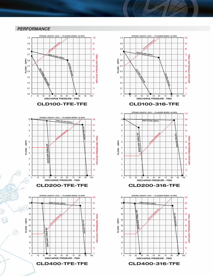
PERFORMANCE
0 10 20 30 40 50 60 70 80 90 100
0.9
1.0
0.8
0.7
0.6
0.5
0.4
0.3
0.2
0.1
0.0
90
100
80
70
60
50
40
30
20
10
0
FLO
W -
GP
H
STROKE LENGTH: 100% • PLUNGER SPEED: 45 SPM
AIR
/GA
S P
RE
SS
UR
E P
SIG
100
PS
IG A
IR/G
AS
50 P
SIG
AIR
/GAS
AIR/G
AS PRESSURE
DISCHARGE PRESSURE - PSIG
LD100-TFE-TFE
MAX FLOW (GPH)
CLD100-TFE-TFE
0 10 20 30 40 50 60 70 80 90 100
90
100
80
70
60
50
40
30
20
10
0
0.9
1.0
0.8
0.7
0.6
0.5
0.4
0.3
0.2
0.1
0
FLO
W -
GP
H
STROKE LENGTH: 100% • PLUNGER SPEED: 45 SPM
DISCHARGE PRESSURE - PSIG
LD100-316-TFE
AIR
/GA
S P
RE
SS
UR
E P
SIG
100
PS
IG A
IR/G
AS
AIR/G
AS PRESSURE
50 P
SIG
AIR
/GAS
MAX FLOW (GPH)
CLD100-316-TFE
0 10 20 30 40 50 60 70 80 90 100
9
10
8
7
6
5
4
3
2
1
0
90
100
80
70
60
50
40
30
20
10
0
FLO
W -
GP
H
STROKE LENGTH: 100% • PLUNGER SPEED: 45 SPM
AIR
/GA
S P
RE
SS
UR
E P
SIG
100
PS
IG A
IR/G
AS
AIR/G
AS PRESSURE
35
PS
IG A
IR/G
AS
DISCHARGE PRESSURE - PSIG
LD200-TFE-TFE
MAX FLOW (GPH)
CLD200-TFE-TFE
0 10 20 30 40 50 60 70 80 90 100
9
10
11
8
7
6
5
4
3
2
1
0
90
100
110
80
70
60
50
40
30
20
10
0
FLO
W -
GP
H
STROKE LENGTH: 100% • PLUNGER SPEED: 45 SPM
AIR
/GA
S P
RE
SS
UR
E P
SIG
100
PS
IG A
IR/G
AS
AIR/G
AS PRES
SURE
35
PS
IG A
IR/G
AS
DISCHARGE PRESSURE - PSIG
LD200-316-TFE
MAX FLOW (GPH)
CLD200-316-TFE
0 10 20 30 40 50 60 70 80 90 100
45
50
40
35
30
25
20
15
10
5
0
90
100
80
70
60
50
40
30
20
10
0
FLO
W -
GP
H
STROKE LENGTH: 100% • PLUNGER SPEED: 45 SPM
AIR
/GA
S P
RE
SS
UR
E P
SIG
100
PS
IG A
IR/G
AS
AIR/G
AS PRESSURE
35
PS
IG A
IR/G
AS
DISCHARGE PRESSURE - PSIG
LD400-TFE-TFE
MAX FLOW (GPH)
CLD400-TFE-TFE
0 10 20 30 40 50 60 70 80 90 100
45
50
40
35
30
25
20
15
10
5
0
90
100
80
70
60
50
40
30
20
10
0
FLO
W -
GP
H
STROKE LENGTH: 100% • PLUNGER SPEED: 45 SPM
AIR
/GA
S P
RE
SS
UR
E P
SIG
100
PS
IG A
IR/G
AS
AIR/G
AS PRESSURE3
5 P
SIG
AIR
/GA
S
DISCHARGE PRESSURE - PSIG
LD400-316-TFE
MAX FLOW (GPH)
CLD400-316-TFE
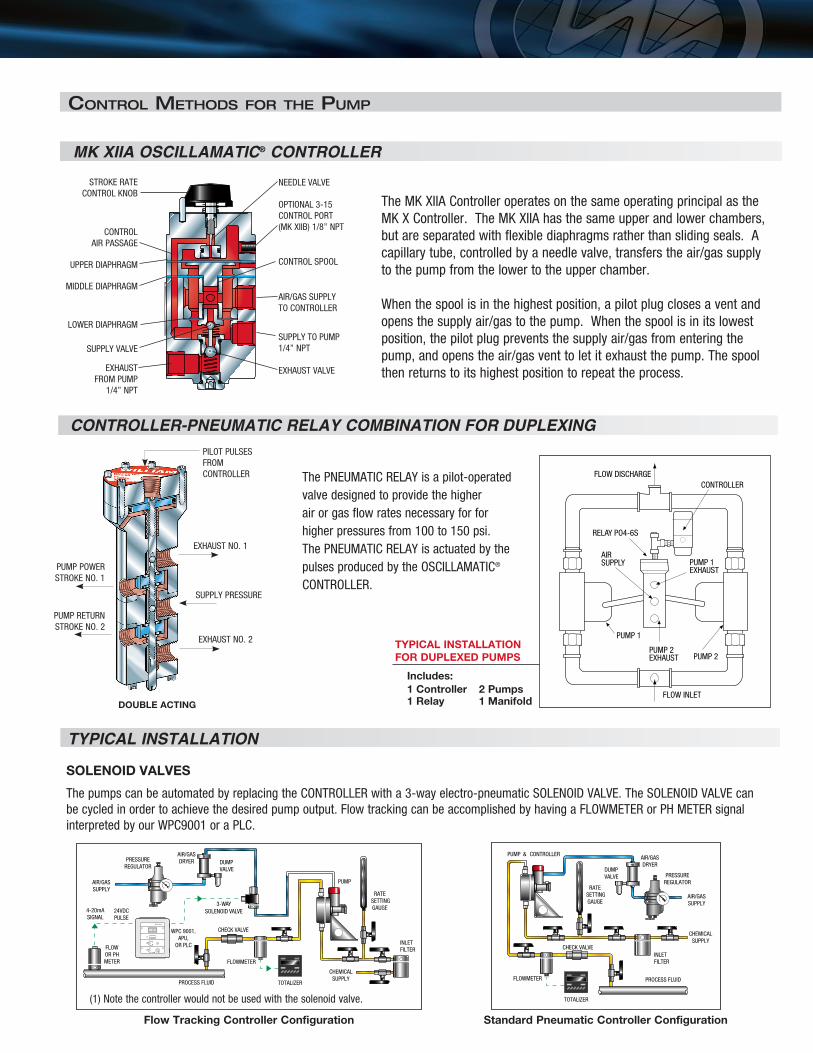
The MK XIIA Controller operates on the same operating principal as the MK X Controller. The MK XIIA has the same upper and lower chambers, but are separated with flexible diaphragms rather than sliding seals. A capillarytube,controlledbyaneedlevalve,transferstheair/gassupplyto the pump from the lower to the upper chamber.
When the spool is in the highest position, a pilot plug closes a vent and opensthesupplyair/gastothepump.Whenthespoolisinitslowestposition,thepilotplugpreventsthesupplyair/gasfromenteringthepump,andopenstheair/gasventtoletitexhaustthepump.Thespoolthen returns to its highest position to repeat the process.
Control Methods for the PuMP
MK xIIA OSCILLAMATIC® CONTROLLER
FLOW DISCHARGECONTROLLER
RELAYPO4-6S
PUMP 1EXHAUST
AIR SUPPLY
PUMP 2EXHAUST
PUMP 1
PUMP 2
FLOW INLET
CONTROLLER-PNEUMATIC RELAY COMBINATION FOR DUPLExING
TYPICAL INSTALLATIONFOR DUPLExED PUMPS
Includes:1 Controller 2 Pumps1 Relay 1 ManifoldDOUBLE ACTING
TYPICAL INSTALLATION
SOLENOID VALVES
ThepumpscanbeautomatedbyreplacingtheCONTROLLERwitha3-wayelectro-pneumaticSOLENOIDVALVE.TheSOLENOIDVALVEcanbe cycled in order to achieve the desired pump output. Flow tracking can be accomplished by having a FLOWMETER or PH METER signal interpretedbyourWPC9001oraPLC.
PUMP & CONTROLLER
DUMPVALVE
AIR/GASDRYER
PRESSUREREGULATOR
AIR/GASSUPPLY
INLETFILTER
CHEMICALSUPPLY
3-WAY SOLENOID VALVE
FLOWOR PHMETER
PROCESS FLUID
PROCESS FLUID
WPC9001,APU,
OR PLC
24VDCPULSE
4-20mASIGNAL
CHECK VALVE
FLOWMETER
TOTALIZER
PUMP
DUMPVALVE
AIR/GASDRYERPRESSURE
REGULATOR
AIR/GASSUPPLY
CHECK VALVE
RATE SETTINGGAUGE
RATE SETTINGGAUGE
INLETFILTER
CHEMICALSUPPLY
6 0 0
W P C 9 0 0 1
FLOWMETER
TOTALIZER
Flow Tracking Controller Configuration
(1)Notethecontrollerwouldnotbeusedwiththesolenoidvalve.
Standard Pneumatic Controller Configuration
ThePNEUMATICRELAYisapilot-operatedvalve designed to provide the higher air or gas flow rates necessary for for higherpressuresfrom100to150psi.The PNEUMATIC RELAY is actuated by the pulses produced by the OSCILLAMATIC® CONTROLLER.
STROKE RATECONTROL KNOB
NEEDLE VALVE
CONTROL SPOOL
AIR/GASSUPPLYTO CONTROLLER
SUPPLY TO PUMP1/4”NPT
EXHAUST VALVE
OPTIONAL3-15CONTROL PORT(MKXIIB)1/8”NPTCONTROL
AIR PASSAGE
UPPER DIAPHRAGM
MIDDLE DIAPHRAGM
LOWER DIAPHRAGM
SUPPLY VALVE
EXHAUST FROM PUMP
1/4”NPT
SUPPLY PRESSURE
EXHAUSTNO.1
PUMP POWER STROKENO.1
PUMP RETURN STROKENO.2
EXHAUSTNO.2
PILOT PULSESFROMCONTROLLER
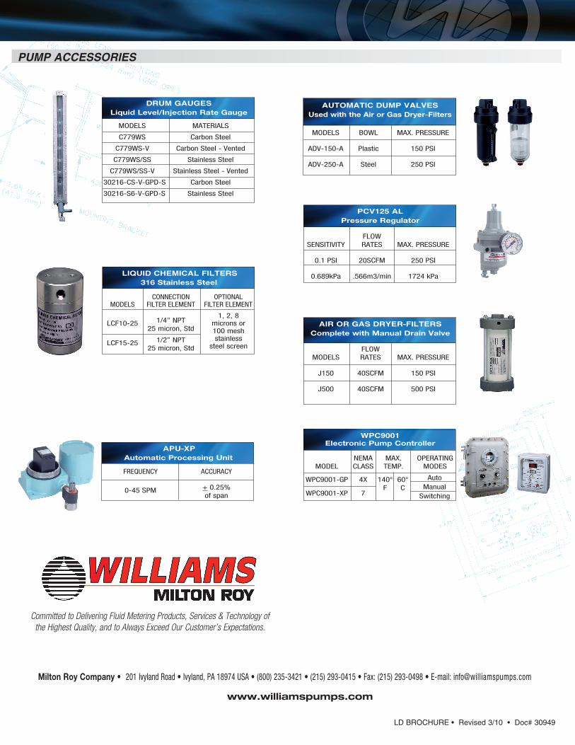
Committed to Delivering Fluid Metering Products, Services & Technology of the Highest Quality, and to Always Exceed Our Customer’s Expectations.
PUMP ACCESSORIES
AIR OR GAS DRYER-FILTERSComplete with Manual Drain Valve
FLOW MODELS RATES MAX. PRESSURE
J150 40SCFM 150PSI J500 40SCFM 500PSI
PCV125 ALPressure Regulator
FLOW SENSITIVITY RATES MAX. PRESSURE
0.1PSI 20SCFM 250PSI 0.689kPa .566m3/min 1724kPa
AUTOMATIC DUMP VALVESUsed with the Air or Gas Dryer-Filters
MODELS BOWL MAX. PRESSURE
ADV-150-A Plastic 150PSI ADV-250-A Steel 250PSI
LIQUID CHEMICAL FILTERS316 Stainless Steel
CONNECTION OPTIONAL MODELS FILTER ELEMENT FILTER ELEMENT LCF10-25 1/4”NPT 25micron,Std
LCF15-25 1/2”NPT 25micron,Std
1,2,8microns or 100meshstainless
steel screen
APU-XPAutomatic Processing Unit
FREQUENCY ACCURACY 0-45SPM +0.25% of span
DRUM GAUGESLiquid Level/Injection Rate Gauge
MODELS MATERIALS
C779WS CarbonSteel
C779WS-V CarbonSteel-Vented
C779WS/SS StainlessSteel
C779WS/SS-V StainlessSteel-Vented
30216-CS-V-GPD-S CarbonSteel
30216-S6-V-GPD-S StainlessSteel
WPC9001Electronic Pump Controller
NEMA MAX. OPERATING MODEL CLASS TEMP. MODES
WPC9001-GP 4X 140° 60° Auto
F C ManualWPC9001-XP 7 Switching
Milton Roy Company • 201IvylandRoad•Ivyland,PA18974USA•(800)235-3421•(215)293-0415•Fax:(215)293-0498•E-mail:[email protected]
www.williamspumps.com
LD BROCHURE • Revised 3/10 • Doc# 30949
Related Documents