Structural Analysis of Historical Constructions - Modena, Lourenço & Roca (eds) © 2005 Taylor & Francis Group, London, ISBN 04 1536 379 9 Strengthening and controI methods for oId timber trusses: the queen-post truss of the Trento theatre M.P. Piazza & M.R. Riggio Department of Meehanieal and Strue/ural Engineering, University ofTrento, l/aly G.B. Brentari Holzbau SpA, Brixen, lta/ y ABSTRACT: Retrofitting interventions on traditional timber structures are often difficult to quantify because of the lack of adequate behavior models for both the original and the upgraded structural components. The consecutive operational stages of this research substantiate a procedure for the analysis and the strengthening of old timber structures. Full-scale experimentation and a numerical study by finite element analysis have been used in order to observe the elastic behavior of a queen-post truss salvaged from a XIX century roof, that was demolished during the retrofitting works of the Trento theatre. The assembly of the truss and the restoration interventions have been preceded by the experimental determination of the material properties. Testing with symmetric and nonsymmetric loading on the assembled structure followed, permitting some observations on local behavior and allowing the experimental validation ofthe proposed analytical models. INTRODUCTION According to the general interest for the recovery and maintenance of old traditional timber trusses, a spe- cific research program is being carried out at the Department of Mechanical and Structural Engineer- ing in the University ofTrento. The major aim of the research is to point out methods and techniques for an exhaustive study of timber structures, to make a reli- able assessment of their healthiness and to ensure the maintenance ofthe required safety leveis. The chance to carry out a circumstantial and com- prehensive research on the behaviour oftimber trusses carne up during the restoration works of the Trento Theatre (Teatro Social e), started in March 1998 and completed in 200 I. A portion of the timber structure covering the stage has been replaced with new ele- ments and different materiais. Two ofthe trusses, that constituted the primary load-bearing structure of the roof, have been removed from the original location and used to reconstruct a single one in the Structural Testing Laboratory ofthe University ofTrento. The research process has been performed in labo- ratory but can be as well applied in-situoIts stages can be summed up as following: historical-typological analysis, by collecting infor- mation about the past history of the studied 957 structure, as well as about the historical evolution ofthe specific structural typology; 2 analysis of the structural members, by acquiring data about the geometry, the technological and the mechanical parameters (survey of the geometric data, of the original defects and of the subsequent biotic decay and mechanical damages); 3 analysis ofthe connections, with the assessment of the static "efficiency" (backlashes, disconnections, etc.), in particular regarding possible biotic attacks, warping or cracks; 4 recovery of the specific element, choosing the more appropriate technique to restore the longitu- dinal continuity, between the different parts of the same element as well as ofthe connection between different elements, trying to preserve the origi- nai mechanical behaviour and conception of the structure; 5 installation, in laboratory; 6 numerical analysis of the structure, by means of a detailed finite element model, to take into account the effective geometric and mechanical features of each element, as well as the semi-rigid behaviour ofthe connections; 7 laboratory testing, carried out to validate and to sup- port the numerical model, as well as to control the effectiveness of the intervention;

Welcome message from author
This document is posted to help you gain knowledge. Please leave a comment to let me know what you think about it! Share it to your friends and learn new things together.
Transcript
Structural Analysis of Historical Constructions - Modena, Lourenço & Roca (eds) © 2005 Taylor & Francis Group, London, ISBN 04 1536 379 9
Strengthening and controI methods for oId timber trusses: the queen-post truss of the Trento theatre
M.P. Piazza & M.R. Riggio Department of Meehanieal and Strue/ural Engineering, University ofTrento, l/aly
G.B. Brentari Holzbau SpA, Brixen, lta/y
ABSTRACT: Retrofitting interventions on traditional timber structures are often difficult to quantify because of the lack of adequate behavior models for both the original and the upgraded structural components. The consecutive operational stages of this research substantiate a procedure for the analysis and the strengthening of old timber structures. Full-scale experimentation and a numerical study by finite element analysis have been used in order to observe the elastic behavior of a queen-post truss salvaged from a XIX century roof, that was demolished during the retrofitting works of the Trento theatre. The assembly of the truss and the restoration interventions have been preceded by the experimental determination of the material properties. Testing with symmetric and nonsymmetric loading on the assembled structure followed, permitting some observations on local behavior and allowing the experimental validation ofthe proposed analytical models.
INTRODUCTION
According to the general interest for the recovery and maintenance of old traditional timber trusses, a specific research program is being carried out at the Department of Mechanical and Structural Engineering in the University ofTrento. The major aim of the research is to point out methods and techniques for an exhaustive study of timber structures, to make a reliable assessment of their healthiness and to ensure the maintenance ofthe required safety leveis.
The chance to carry out a circumstantial and comprehensive research on the behaviour oftimber trusses carne up during the restoration works of the Trento Theatre (Teatro Social e ), started in March 1998 and completed in 200 I. A portion of the timber structure covering the stage has been replaced with new elements and different materiais. Two ofthe trusses, that constituted the primary load-bearing structure of the roof, have been removed from the original location and used to reconstruct a single one in the Structural Testing Laboratory ofthe University ofTrento.
The research process has been performed in laboratory but can be as well applied in-situo Its stages can be summed up as following:
historical-typological analysis, by collecting information about the past history of the studied
957
structure, as well as about the historical evolution ofthe specific structural typology;
2 analysis of the structural members, by acquiring data about the geometry, the technological and the mechanical parameters (survey of the geometric data, of the original defects and of the subsequent biotic decay and mechanical damages) ;
3 analysis ofthe connections, with the assessment of the static "efficiency" (backlashes, disconnections, etc.), in particular regarding possible biotic attacks, warping or cracks;
4 recovery of the specific element, choosing the more appropriate technique to restore the longitudinal continuity, between the different parts of the same element as well as ofthe connection between different elements, trying to preserve the originai mechanical behaviour and conception of the structure;
5 installation, in laboratory; 6 numerical analysis of the structure, by means of a
detailed finite element model, to take into account the effective geometric and mechanical features of each element, as well as the semi-rigid behaviour ofthe connections;
7 laboratory testing, carried out to validate and to support the numerical model , as well as to control the effectiveness of the intervention;

8 assessment of the serviceability and the safety of the truss, according to the current codes on timber structures .
2 TYPOLOGICAL AND TECHNOLOGICAL ANALYSIS
The trusses date from the nineteenth century (18 19) and are of great historical and cultural significance, as example of traditional timber structures stil l in general good condition.
The dimensions (length 25 ,4 m, height 6,4 m) of the studied truss are considerable. The typology of the queen-post truss fits the wide span. Indeed, the compressed top chord reduces the bending moment of the upper rafter, while the lower one increase the load bearing capabil ity of the rafier in the most stressed sections, effectively connecting it to the struts . In this case lower and upper rafier were not jointed, hence they act as two separated beams. The origi nal interface between them has been replaced, in laboratory, by timber shims. As regards the carpenter connections, birdsmouth joints with a "single tooth" connect the double rafier to the chord and the strut to the lower rafter; mortise and tenon joints connect the king-post to the upper, continuous rafier, as well as the queen-post to the lower rafier and to the upper chord. The queen-posts are tied to the chord, as well as the king-post to the tie beam by means of bolted connections.
Extensive nondestructive testing on the disassembled beams, associated wi th the so called "visual grading", was performed in order to characterize the mechanical properties of the material.
A visual inspection of the truss was preliminary performed, searching for the main natural defects (knots, fissures, resin pockets, etc.) and biological degradation.
The most criticaI decay factor of the lumber was represented by dry rot attacks, concentrated on the chord and rafiers ends, at the supports, where moisture typically stands.
An accurate survey of the geometric data is a prerequisite in the study of old timber beams, which ofien diverge from the theoretical "beam model", namely a prismatic bar with rectangular cross section. Ali the wood members were surveyed at the distance of every 100 cm and each cross section were represented by eight parameters, obtained by straightlining the corners.
Besides the geometrical features some physical properties (density, moisture content) had to be assessed, in order to process the data from nondestructive testing. Density was derived from the ratio between mass and volume of each element, the data for moisture content were determined using the electrical
resistance moisture meter, namely the hygrometric tests quoted below.
The identified wood species ofthe truss are white fir (Abies alba Mill.) and red spruce (Picea abies Karst. ).
2.1 NDT testing
Among the different ND test procedures commonly available for the determination ofthe modulus ofelasticity, techniques based on dynamic measures, on ultrasonic methods and on indirect measure of density have been used.
In particular, the performed nondestructive tests have been the fo llowing: 960 hygrometric tests (Hydroette HT 95), 60 dynamic tests (ONO SOKI, CF-350), 180 Ultrasound tests (Sylvatest®), 2052 sclerometer tests (Pi lodyn® 2J), 1640 hardness tests (Piazza M., Baldassino N. & Zanon P. 1996),9 1 micro drill resistance measurements (Resistograph® 1410).
As regards the dynamic tests (NDT I), an accelerometer, an instrumented hammer and a FFT ana1yser have been used. The fundamental frequency of longitudinal vibration with the element centrally supported has been measured.
Ultrasound test methods are amenable to three basic approaches:
pulse-echo method: employed to scan the geometry of the lumber;
2 grain-sound-tracing method: used to trace outgoing knots;
3 trough-transmission method: used fo r detecting internai defects of the wood.
In the third method, the wave is supposed to travei radially or through the beam center. The latter mode has been adopted, wi th the transducers placed at the ends ofthe element, in order to evaluate the dynamic elastic modulus through the timber elements. The dynamic elastic modulus has been assessed with the Sylvatest following two different modalities:
• (NDT2) the classic test, in which the dynamic elastic modulus is computed given the absolute gravity and the speed of the wave through the wood;
• (NDT3) the test according to the manufacturer, that takes into account also the moisture levei and the temperature of the wood.
Arnong the ND methodologies based on an indirect measure ofthe density of the wood, the following tests were chosen:
sclerometer test, that measures the penetration of a steel pin (Pi lodyn), driven into the wood with a constant energy;
2 hardness test on the lateral surface of the element; the measures were made in five positions (equally spaced along the element) for each lateral side, each measure is the mean of f ive different tests;
958

3 measure of the drilling resistance during the penetration into the wood of a drill bit (Resistograph).
The results, gathered with the nondestructive testing, have been compared with the modulus ofelasticity (MoE) ofthe beams determined through the so called four-point bending test, according to EN 408, as outlined in Table I. The mean errors of the performed sclerometer and Ultrasound tests, highlight the inadequacy of the used instruments to assess old timber members. On the contrary dynamic tests have proven to be rather effective, as well as the hardness tests. However the latter requires a sensitivity study of the material decay and defects. Micro drill resistance measurements gave information about the decay of wood material inside the element, but are inadequate to measure the elastic modulus ofthe wood.
Table I. Results [MPaJ of the ND tests on some elements of the truss.
Element NDTI NDT2 NDT3 NDT4 M.o.E
ais 14.110 13.733 16.160 12 .067 12.300 aI/ 11.467 13.533 13.659 10.9 12 10.600 a3d 12.230 11 .833 14.358 11.595 1/.100 bis 13.899 15.200 16.522 10.797 10.900 b2 12.896 15.600 15.906 10.835 10.300 b3d 11.542 13 .133 13.578 10.897 12.500 ai 2p,a 15.508 15.333 17.793 12.279 9.600' al2p,b 14.943 15.000 16.770 12.264 12.400 a2p,b 10.619 12.600 12.724 11.230 10.000 blp,a 14.298 13.933 17.038 11.738 12.600 bl2p,a 13.905 14.533 16.767 11.215 11.000 b2 10.142 12.500 11.428 9.946 9.800 b8 10.185 12.400 12.094 10.689 10.700 a8 12.402 15.333 14.396 10.100 11.400
with: NDT I elastic modulus from dynamic test results, NDT2 from the classic ultrasonic test, NDT3 from the ultrasonic test according to the manufacturer, NDT4 from the hardness test and M.o.E. real elastic modulus according to EN 408.
A12p,a
Bls
Figure I. The assembled truss: elements and assembling joints.
959
In any case, grading oflumber in new as well in old structures, has to be performed with the interaction of several nondestructive testing, in order to reduce the unavoidable errors in the assessment ofthe mechanical properties of the material.
3 RETROFITTING PRASE
The adopted strengthening techniques refer to the execution of"mixed" structures, which resort to the use of other materiaIs, to collaborate with the original timber. Generally these techniques are amenable to two basic approaches: the embedding of reinforcement materiaIs in the wood, and the use of externaI collaborating elements (Piazza M. & Parisi M.A. 2000). The former approach has been adopted, in order to restore the truss .
The continuity within the damaged elements, mutilated during the disassembly, has been recovered by means of glued-in metal rods, 24 mm in diameter, connecting the facing cross sections of each member piece. The carpenter joints have been retrofitted by means of classic "dry" connectors, which do not resort to the use of glue. The birdsmouthjoint connecting the chord to the double rafter has been strengthened with large screws, 10 mm in diameter and 400 mm longo At the supports, the toe area of the chord, as well as of the comparatively thin edge of the rafter, has been reinforced by scattered screws in predrilled holes, in order to avoid the collapse in shear parallel to the fiber at the chord toe.
The connection between the console and the chord has been recovered by means of a dovetail timber connector.
Globally, reinforcing devices have been selected to improve the joint response, respecting the original conceptual design ofthe traditional timber friction-based connection, transmitting forces by direct contact on facing elements. For this reason, the use of devices that would stiffen the joint completely, inducing a different
stress distribution in the structure and preventing even relative movements of the connected elements, have been avoided (Parisi M.A. Piazza M. 2002b).
4 EXPERIMENTAL ANALYSIS
The experimental analysis ofthe assembled and recovered truss was carried out at the Structural Testing Laboratory ofthe Univers ity ofTrento.
4.1 Test setup and instrumentation
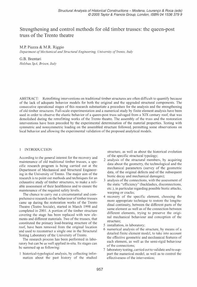
A scaffold and a steel loading frame were built in the laboratory. The testing apparatus mounting the truss is shown in Figure 2. Tests have been carried out with symrnetric and nonsymrnetric loading in monotonic modes. While the conditions on the truss in service consisted basically of the loads transmitted by the purlins set, testing has been performed with load partitioning beams that loaded two points of each rafier, nearly in the position of the former two central purlins. The arrangement allows separate
Figure 2. Testing layout for the roof truss.
Figure 3. The tested rooftruss.
contraI of two hydraulic jacks, in order to permit the nonsymrnetric tests.
Tests were performed under displacement contraI. The truss has been instrumented with 30 linear
voltage differential transducers (LVDT). Types and locations of measuring instruments, including load cells, transducers and strain gauges are shown in Figure 3.
The instrumented points are numerous, in order to minutely describe the behavior of the truss in terms of displacements. In particular instruments have been located at the connections between lower rafter and strut (13, 14, \3d, 14d), strut and queen-post (17, 17 d), upperrafier and tie beam (28, 29, 30), double rafier and chord (05 , 06, 07, 05d, 06d, 07d), in order to monitor the opening and closing of the skew angles, while instruments at the points II and 11 d monitored the shifi of the contact planes at the double rafier.
Other instruments have been positioned directly under the loads (22, 23, 22d, 23d), supports (01 , 02 O I d, 02d), the queen-post/chord connections (19, 21) and the center of the chord (20).
4.2 Loading
Testing has been carried out with loading intended to appraximate the service load and within the linearity limit, in order to preserve the truss fram failure and make further experimentation possible. A fruitfuI interaction between experimentation and numerical analysis permitted investigators to adequately prepare the former on the basis of first numerical results. Hence, dead and live loads of the originalload condition of the truss have been set and the corresponding load parameters for the experimental test have been singled out by means of a preliminary numerical analysis.
Ten monotonic tests have been carried out in load contraI. Figure 4 and Table 2 show respectively symmetric and nonsymrnetric tests.
Test results both in terms of loading and unloading have been considered only for the symrnetric
960

case; indeed, the unloading traces of the nonsymmetric tests were affected by inaccuracy, being the flow-control of the valves, connected to the hydraulic jacks, manually-commanded.
4.3 Experimental results
The experimental results were expressed in terms of force versus displacement. Diagrams registered during the tests have confirmed linearity. Indeed, the load-displacement test records associated to the different loading conditions are characterized by the same curve trend on loading (Fig. 5), save for some particular points of the structure (supports and other contact areas). The discrepancy between the unloading traces has not to be attribute to a hysterical
F(kN) 135,--- - ----------------, 120 - -- - - - - - - - -- ----- -- -- - -- - - -- - - - - - - --105
90
75
60 45
30 15
o ~~ o 8
Figure 4. Loading traces of the symmetric tests.
Table 2. Loading rates (kN) of the nonsymmetric tests.
Test Leftjack Rightjack
1 2 3 4 5 6
35 O
49 40 94 83
o 35 35 49 79 94
Figure 5. Diagram load versus di splacement for LVDT transducer 24d, symmetric tests, loading cycles up to 28 kN, 74kN, 94kN, 128kN.
961
behavior of the structure, but to the typical sensitivity of timber structures to the loading rate . Indeed, a reversible component of creep occurred, which disappeared with the time-delayed elastic behavior, due to the viscoelasticity ofthe material.
Furthermore, no significant change of stiffness appears in the behavior curve during alternate load cycles.
Data from testing have been gathered with the purpose of characterizing the behavior of the truss as well as calibrating and validating corresponding numerical models.
Tests gave information about some local deformative mechanisms, which could not be highlighted by numerical analysis. Indeed, a certa in asymrnetry ofthe deformed shape ofthe truss, had to be ascribed both to a gap occurring in the joint connecting the left rafter with the king-post and to fissures in the left supports. The forme r caused the deferred loading of the right and left side ofthe truss , the latter the alternate c10sing and opening ofthe fissures themselves, on loading and unloading respectively. These local effects would be easily overlooked or misinterpreted with a numerical model.
The fruitful interaction between experimentation and numerical analysis is highlighted once more by the possibility of expressing more realistic models to observe the experimental response ofthe structure. In particular, the sti ffness to assign to the mortise and tenon joints has been gathered from the experimental results.
5 NUMERICAL MODELING
The structural analysis program SAP 2000 has been used to model the truss. The choice of the software package has been suggested by the aim of substantiating a procedure for the analysis of old timber structures, that has to conjugate effectiveness and large-scale feasibility.
5.1 Material model
As regards the material modeling, timber is assumed as orthotropic in the system of so-called anatomic cylindrical coordinates corresponding to the longitudinal , L, radial , R, and transversal , T , directions of the tree trunk. Cylindrical coordinates may be approximated as orthogonal, for the material extracted from the outer region ofthe trunk. The elastic moduli , for an axisymmetric model, are Eo in the direction along the fiber, and E90 orthogonal to it, plus a shear modulus, G, and a Poisson's ratio, v . According to the EN 338, E90 can be assumed equal to one-thirtieth of Eo. The elastic moduli of ali the truss elements have been derived from the results of the static bending tests.
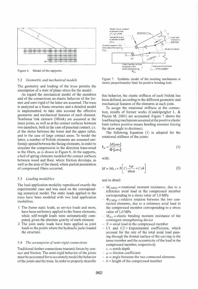
Figure 6. Model of the supports.
5.2 Geometric and mechanical models
The geometry and loading of the truss permits the assumption of a state of plane stress for the model.
As regard the mechanical model of the members and of the connections an elastic behavior of the former and semi-rigid ofthe latter are assumed. The truss is analyzed as a frame structure and a detailed model is implemented, to take into account the effective geometric and mechanical features of each element. Nonlinear link element (Nllink) are assumed at the inner joints, as well as at the contact surfaces between two members, both in the case ofpunctual contact, i.e. at the shims between the lower and the upper rafier, and in the case of large contact areas. To model the latter, a number ofNnlink elements are asswned uniformly spread between the facing elements, in order to simulate the compression in the direction transversal to the fibers, as is shown in Figure 6. At the supports, a bed of spring elements modeled the contact surfaces between wood and fioor, where friction develops, as well as the area ofthe chord, where partial penetration of compressed fibers occurred.
5.3 Loading modalities
The load application modality reproduced exactly the experimental case and was used on the corresponding numerical model. The static loads applied to the truss have been modeled with two load application modalities.
The frame static loads, as service loads and snow, have been uniformly applied to the frame elements, while self-weight loads were automatically computed, given the absolute gravity of each element.
2 The joint static loads have been applied as joint loads to the points where the hydraulic jacks loaded the structure.
5.4 The assumption of semi-rigid connections
Traditional timber connections transmit forces by contact and friction . The semi-rigid behavior of the joints must be accounted for to accurately model the behavior ofthe joints and the truss. In order to properly describe
Friction forces resultanl ai adhrence limil IIC 1ocbl.jcos{J
Tangential slress ai adherence limil JI C 10 c
Elastic bending moment resislanca 01 lhe device slrenglhening
Met.s
Figure 7. Synthetic model of the resisting mechanism at elastic proportionality limit for positive bending load.
this behavior, the elastic stiffness of each Nnlink has been defined, according to the different geometric and mechanical features of the elements at each joint.
To assign the rotational stiffness at the connection, results of former works (Candelpergher L. & Piazza M. 2001) are accounted. Figure 7 shows the load bearing mechanism assumed at the positive elastic Iimit (where positive means bending moment forcing the skew angle to decrease).
The following Equation (I ) is adopted for the rotational stiffness of the joints:
k _ M[IMpa] eI - <l> [IMPa ]
with:
M=Mel,s+N CI-.-+C2h [ /vll ]
sma
and in detail :
(1 )
(2)
- M[IMPa] = rotational moment res istance, due to a reference axial load in the compressed member corresponding to a stress value of 1 ,O MPa <I>[IMPa] = relative rotation between the two connected elements, due to a reference axial load in the compressed member corresponding to a stress value of 1,0 MPa
- Mel,s = elastic bending moment resistance of the contingent strengthening device
- N = axial load in the compressed member C 1 and C2 = Experimental coefficients, which account for the rate of the total axial load passing through the frontal surface ofthe carving in the tense member and the eccentricity ofthe load in the compressed member, respectively Iv = notch depth J.l = friction coefficient ct = angle between the two connected elements h = height of the compressed member
962
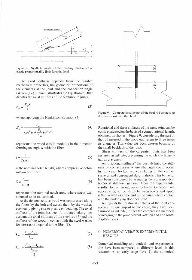
Figure 8. Synthetic model of the resisting mechanism at elastic proportionality limit for axial load.
The axial stiffness depends from the lumber mechanical properties, the geometric proportions of the elements at the joint and the connection angle (skew angle). Figure 8 illustrates the Equation (3), that denotes the axial stiffness of the birdsmouth joints.
k = EaS ax I
where, applying the Hankinson Equation (4):
E = Eo a E
cos2 a + _ o sin 2 a E 90
(3)
(4)
represents the wood elastic modulus in the direction forming an angle ex with the fiber.
1=_11_ 2sina
(5)
is the nominal notch length, where compressive deformation occurred.
S = Ar•fi"
sina (6)
represents the nominal notch area, where stress was assumed to be transmitted.
At the tie connections wood was compressed along the fibers by the bolt and across them by the washer, eventually giving rise to plastic embedding. The axial stiffness of the joint has been formulated taking into account the axial stiffness of the steel rod (7) and the stiffness of the wood in contact with the steel washer for stresses orthogonal to the fiber (8).
(7)
(8)
I I I I I I I I I I
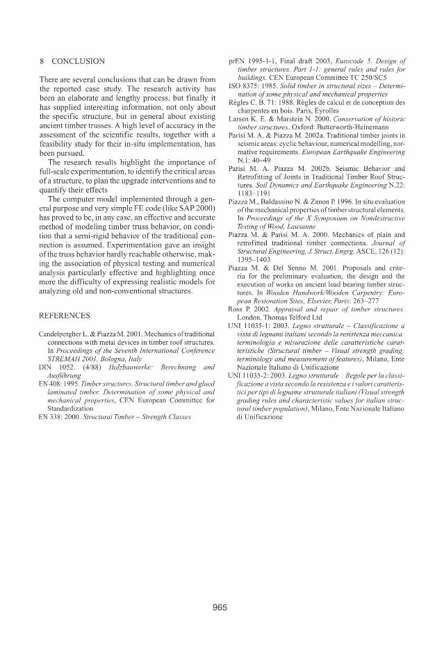
Figure 9. Computationallength ofthe steel rod connecting the queen-post with the chord.
Rotational and shear stiffness ofthe same joint can be easily evaluated on the basis ofa computationallength, obtained, as shown in Figure 9, considering the part of the rod inserted in the wood equivalent to three times its diameter: This value has been chosen because of the small backlash of the joint.
Shear stiffness of the carpenter joints has been assumed as infinite, preventing the notch any tangential displacement.
As "frictional stiffness" has been defined the stiffness of contact areas where slippages could occur. In this case, friction reduces sliding of the contact surfaces and consequent deformations. This behavior has been considered by assigning the correspondent frictional stiffness, gathered from the experimental results, to the facing areas between king-post and upper rafter, to the shims between lower and upper rafter, as well as at the end of the truss, where contact with the underlying floor occurred.
As regards the rotational stiffness of the joint connecting the queen-post to the chord, they have been assumed as infinite, in fact the compressed members converging to the joint prevent rotation and horizontal displacements.
6 NUMERICAL VERSUS EXPERIMENTAL RESULTS
Numerical modeling and analysis and experimentation have been compared at different leveis in this research. At an early stage (levei I) , the numerical
963

model has been implemented without considering the real behavior of the truss observed in the performed tests . At a further stage (leveI lI), the model is verified versus experimental results and therefore calibrated. Comparing computed and measured displacements at various locations in the symmetric loading, a maximal erro r of 17% occurred at leveI I while at leveI Il the error fell to 6%. As regards nonsymmetric loading the maximal error rose to 21 % for leveI I and to 12% for leveI lI. Hence, model is more accurate for the symmetric versus the nonsymmetric case, especially for low loading rates. In general, however, the numerical analysis seems to supply satisfactory information in terms of displacements. In fact, total averages have indicated generally satisfactory results and acceptable leveIs of accuracy, in particular at leveI lI, confirming the effectiveness ofthe synergy between numerical and experimental analysis. Further numerical modeling has been implemented, assuming hinged truss and with full-moment transmitting connections respectively, in order to highlight the effectiveness of the semi-rigid assumption. Values obtained with the former assumption and with the latteryielded a maximal error of37% and of 44% respectively. Hence, with the more accurate semi-rigid assumption, a better-defined behavior of the structure is focused.
7 SERVICEABILITY AND SAFETY REQUIREMENTS
The last stage of the research has regarded the assessment of the serviceability and the safety of the truss, according to the current timber-design codes. The EN 1995 instructions have been taken into account to evaluate the general response of the structure. In order to assess the behavior of the connections also other national guidelines (DIN I 052) (Regles C.B. 71) have been considered.
7.1 The lruss in lhe original service condition
In the original service condition, the chord was under service load, being walkable the 10ft, in the area between the two queen-posts.
The analysis ofthe truss for serviceability limit state verified the chord for deflection.
The ultimate state analysis of the truss considered bending and axial stresses in all the elements. The correspondent diagrams (Figures 10- 11) highlighted the main load-bearing role of the truss quadrangular subsystem, composed by the lower rafters, the upper and the lower chord.
While the general structural performance of the truss was verif ied, local problems occurred. In particular the shear resistance of the connection between rafter and chord were prejudiced by the wrong
Figure 10. Axial forces on lhe truss in lhe original service condilion (white = tension; black = compression).
Figure 11. Bending moment on the truss in the original service condition (white = posi tive momenl; black = negalive momenl).
dimensioning of the notch (DIN 1 052). CriticaI areas, where concentrated axial stresses across the fibers occurred, have been identified at the top of the kingpost, as well as the tied connections, corresponding to the embedding area of the washer.
The results of the ultimate state analysis suggested the retrofitting strategies, some of which effectively followed in laboratory, in the former stages of the research. In order to avoid the collapse in shear parallel to the longitudinal fiber at the chord toe, the strengthening of the birdsmouth joint with dry connectors was suggested, and actually performed. To avoid the penetration of compressed fibers at the top ofthe kingpost some retrofitting cri teria are possible, but they require the partial or total replacement ofthe element itself. Indeed, a better local behavior could be achieved replacing the king-post with a stronger element, i.e. with a more resistant lumber, or replacing the top of the member with an element, whose f iber direction were parallel to the axial stress. The embedding at the bolted connections is normally avoided by using larger washers, as indeed done in the reassembled truss.
7.2 The lruss in lhe laboratory
The ultimate state analysis ofthe reassembled truss has been performed, in order to verify the effectiveness of the applied retrofitting techniques.
The performance of the structure under axial stress is similar to the behavior ofthe truss in service, while the high bending moment at the rafters, has to be ascribed to the concentrated loads, corresponding to the hydraulic jacks on the tested truss.
The fai lure, according to lhe numerical model, should occur at the tense edge of the rafters, at a load leveI corresponding to 3,8 times the service load condition (with the maximum value ofvariable loads).
964
8 CONCLUSION
There are several conclusions that can be drawn from the reported case study. The research activity has been an elaborate and lengthy process, but finally it has supplied interesting information, not only about the specific structure, but in general about existing ancient timber trusses. A high levei of accuracy in the assessment of the scientific results, together with a feasibility study for their in-situ implementation, has been pursued .
The research results highlight the importance of full-scale experimentation, to identify the criticai areas ofa structure, to plan the upgrade interventions and to quantify their effects
The compute r model implemented through a general purpose and very simple FE code (like SAP 2000) has proved to be, in any case, an effective and accurate method of modeling timber truss behavior, on condition that a semi-rigid behavior of the traditional connection is assumed. Experimentation gave an insight ofthe truss behavior hardly reachable otherwise, making the association of physical testing and numerical analysis particularly effective and highlighting once more the difficulty of expressing realistic models for analyzing old and non-conventional structures.
REFERENCES
Candelpergher L. & Piazza M. 200 I. Mechanics ortraditional connections with metal devices in timber roof structures. In Proceedings of lhe Seventh International Conference STREMAH 2001, Bologna, Italy
DrN 1052. (4/88) Holzbauwerke: Berechnung and Ausfiihrung
EN 408: 1995. Timber strucllIres. Structurallimberand glued laminated limba Determination of some physical and mechanical properties, CEN European Committee for Standardization
EN 338: 2000. Slruclural Timber - Slrenglh Classes
965
prEN 1995-1-1 , Final draft 2003, Eurocode 5. Design of timber structures. Part I -I: general rules and rules for bui!dings. CEN European Committee TC 250/SC5
ISO 8375: 1985. Solid timber in sll1/ctural sizes - Delermination of some physical and mechanical proper/ies
Regles C. B. 71: 1988. Regles de calcul et de conception des charpentes en bois. Paris, Eyrolles
Larsen K. E. & Marstein N. 2000. Conserva/ion of historie limber slructures . Oxford: Butterworth-Heinemann
Parisi M. A. & Piazza M. 2002a. Traditional timber joints in se ismic areas: cyclic behaviour, numerical modelling, normative requirements. European Ear/hquake Engineering N.!: 40-49
Parisi M. A. Piazza M. 2002b. Seismic Behavior and Retrofitting of Joints in Traditional Timber Roof Structures. Soi! Dynamics and Ear/hquake Engineering N.22: 1183- 1191
Piazza M. , Baldassino N. & Zanon P. 1996. [n situ evaluation ofthe mechanical properties oftimber structural elements. [n Proceedings of lhe X Symposium on Nondeslruclive Testing of Wood, Lausanne
Piazza M. & Parisi M. A. 2000. Mechanics of plain and retrofitted traditional timber connections. Journal of S/rue/ural Engineering. J Struct. Engrg. ASCE, 126 (12): 1395- 1403
Piazza M. & Del Senno M. 2001. Proposals and cri teria for lhe preliminary evaluation, the design and the execution of works on ancient load bearing timber structures. In Wooden HandworklWooden Carpentry: European Res/oralion Si/es, Elsevier, Paris: 263- 277
Ross P. 2002. Appraisal and repair of timber Slruc/ures. London, Thomas Telford Ltd
UNI 11035-1: 2003. Legno slrul/urale - Classificazione a vista di legnami ilaliani secondo la resis/enza meccanica: terminologia e misurazione delle earalleristiche cara 1-
/eris/iche (S/ruc/ural /imber - Visual s/renglh grading: terminology and measuremen/ offea/ures) , Milano, Ente Nazionale Italiano di Unificazione
UNI 11035-2: 2003. Legllo s/rullurale - Regole per la c/assificazione a visfa secondo la resislenza e i valori caralleris/iei per fipi di legname sfrul/urale ilaliani (Visual sfrenglh grading rules and characferisfie values for ilalian Slrucfurai timberpopula/ion) , Milano, Ente Nazionale Italiano di Unificazione

Related Documents