1 Strain modulated band gap of edge passivated armchair graphene nanoribbons Xihong Peng, 1, * Selina Velasquez 2 1 Department of Applied Sciences and Mathematics, Arizona State University, Mesa, AZ 85212 2 College of Technology and Innovation, Arizona State University, Mesa, AZ 85212 ABSTRACT First principles calculations were performed to study strain effects on band gap of armchair graphene nanoribbons (AGNRs) with different edge passivation, including hydrogen, oxygen, and hydroxyl group. The band gap of the H-passivated AGNRs shows a nearly periodic zigzag variation under strain. For O and OH passivation, the zigzag patterns are significantly shifted by a modified quantum confinement due to the edges. In addition, the band gap of the O- passivated AGNRs experiences a direct-to-indirect transition with sufficient tensile strain (~ 5%). The indirect band gap reduces to zero with further increased strain, which may indicate a formation of metallic nanoribbons. Keywords: armchair graphene nanoribbons, uniaxial strain, band structure, band gap, quantum confinement, edge passivation

Welcome message from author
This document is posted to help you gain knowledge. Please leave a comment to let me know what you think about it! Share it to your friends and learn new things together.
Transcript

1
Strain modulated band gap of edge passivated armchair graphene nanoribbons
Xihong Peng, 1,* Selina Velasquez2 1 Department of Applied Sciences and Mathematics, Arizona State University, Mesa, AZ 85212 2 College of Technology and Innovation, Arizona State University, Mesa, AZ 85212
ABSTRACT
First principles calculations were performed to study strain effects on band gap of
armchair graphene nanoribbons (AGNRs) with different edge passivation, including hydrogen,
oxygen, and hydroxyl group. The band gap of the H-passivated AGNRs shows a nearly periodic
zigzag variation under strain. For O and OH passivation, the zigzag patterns are significantly
shifted by a modified quantum confinement due to the edges. In addition, the band gap of the O-
passivated AGNRs experiences a direct-to-indirect transition with sufficient tensile strain (~
5%). The indirect band gap reduces to zero with further increased strain, which may indicate a
formation of metallic nanoribbons.
Keywords: armchair graphene nanoribbons, uniaxial strain, band structure, band gap, quantum
confinement, edge passivation

2
Recently graphene, a two-dimensional (2D) sheet of sp2-bonded carbon honeycomb lattice,
has been considered as a promising material for many advanced applications in future
electronics, such as ballistic single-electron transistors and interconnects.1-3 The 2D graphene
sheet demonstrates a zero band gap. For practical applications in semiconductor technology, the
band gap of graphene has to be tuned to a finite value. A series of strategies were explored to
engineer the band gap of graphene, for example, by applying an external electric field4-7 or
utilizing multilayer graphene structures.7, 8 Tailoring the 2D graphene sheet into nanoribbons has
been one of the promising approaches to create a finite value band gap. Individual factors, such
as size9-14, edge effect,9, 15-17 and external strain,18-23 can be employed to effectively tune the band
gap of the graphene nanoribbons. However, it is still not clear what the combined effects of
these factors are, especially strain and edge passivation, on the band gap of AGNRs
In present work, a theoretical study was conducted to investigate strain modulation of the
band gap of the AGNRs with various edge passivation, including hydrogen, bridged oxygen and
hydroxyl group. It was found that the zigzag pattern of strain-dependence of the band gap is
significantly shifted by different passivation. In addition, a transition from direct to indirect band
gap in the O-passivated AGNRs is observed by applying tensile strain around 5%. The ribbons
could become metallic with further increased tensile strain.
Density-functional theory (DFT)24 calculations were performed using VASP code.25, 26 Local
density approximation (LDA) was applied. In detail, a pseudo-potential plane wave approach
was employed with a kinetic energy cutoff of 400.0 eV. Core electrons were described using
Vanderbilt ultra-soft pseudo-potentials (US-PP).27 Projector augmented wave (PAW)
potentials28, 29 were also used to check the calculations and no significant difference in the results
was found between US-PP and PAW. Reciprocal space was sampled at 4 × 1× 1 using
Monkhorst Pack meshes centered at point. 21 K-points were included in band structure
calculations. Dangling bonds on the edge of AGNRs were saturated in three scenarios: (1) by
hydrogen atoms; (2) by oxygen atoms; and (3) by hydroxyl group (see Fig. 1). The initial lattice
constant in a ribbon was set to be 4.22 Å, taken from the 2D graphene sheet. The lateral size of
the simulation cell in the ribbon plane was chosen so that the vacuum distance between the
ribbon and its replica (due to periodic boundary conditions) is more than 12 Å, and an 8 Å of
vacuum separation was used to eliminate the interaction between ribbon layers. The total energy
was converged to within 0.01 meV. Atoms were fully relaxed until forces are less than 0.02

3
eV/Å. The lattice constant along the armchair direction (i.e. x-axis) of all AGNRs was optimized
through the technique of energy minimization.
The width L and the lattice constant a of a ribbon are defined as in Fig. 1(a). Based on the
relaxed structure of a ribbon with an optimized lattice constant, uniaxial strain within the range
of ±16% was applied by scaling the lattice constant (see Fig. 1(b)). The positive values of strain
refer to uniaxial expansion, while negative corresponds to compression (note that the y and z
coordinates of the ribbon are further relaxed at a given strain). It is known that, due to quantum
confinement effects, AGNRs can be classified into three families according to the width L falling
in the categories of 3n, 3n+1, and 3n+2, where n is a positive integer.21, 23 In present work,
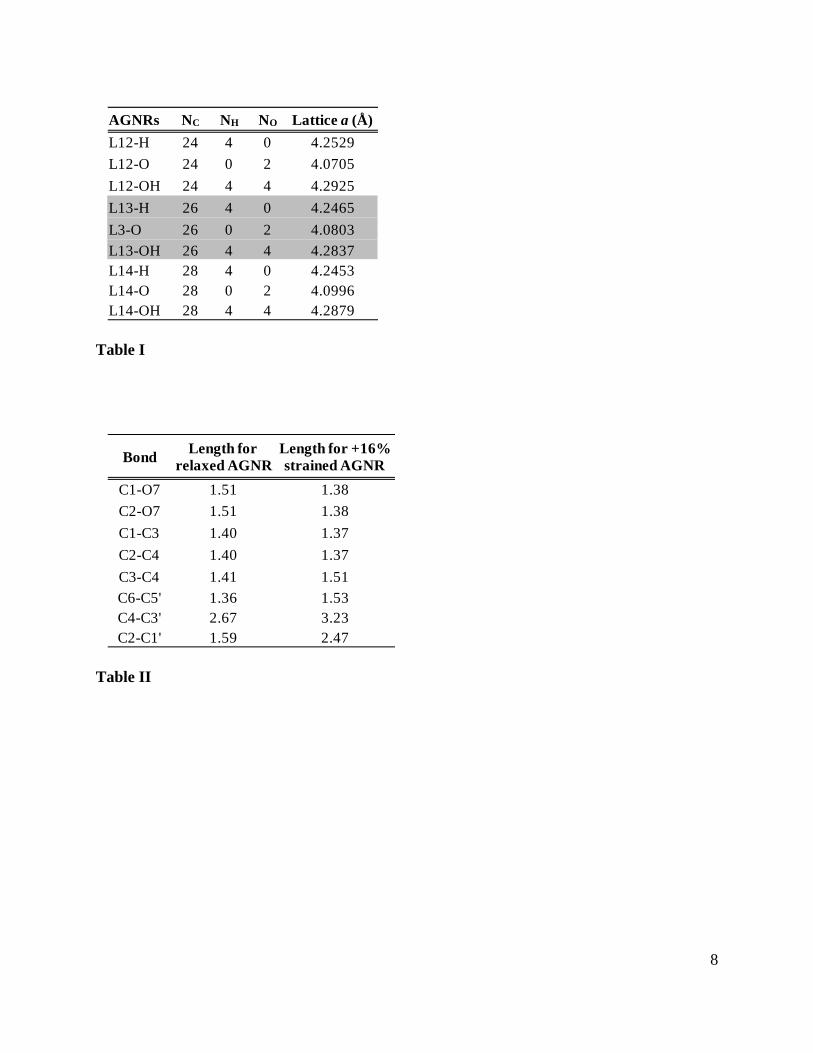
AGNRs with a width of 12, 13, and 14 were chosen to represent those three families. In Table I,
the studied AGNRs are listed with the relaxed lattice constants. It was found that the relaxed
lattice constant varies with the edge passivation for a given width. The OH-passivated AGNR
has the longest lattice constant, while the O-passivated ribbon has the shortest.
Strain effect on the band gap of the AGNRs is presented in Fig. 2. The band gap reported in
the figure is measured at the point. The band gap of the H-passivated AGNRs with different
widths is plotted as a function of strain in Fig. 2(a). The graph shows a zigzag behavior with the
maximum value of the band gap for the AGNRs with the width of 12, 13, and 14 occurring at
+5%, -2%, and -7%, respectively, with the minimum value of the gap appearing at -6%, -10%,
and +1%, respectively. The results are in a good agreement with literature.22, 23 The zigzag
patterns of the band gap with strain have been related to the movement of the Fermi point across
discrete K-lines allowed by quantum confinement effects.21, 23 Fig. 2(b) presents the band gap of
the AGNRs of L = 13 with different edge passivation. Interestingly, the zigzag patterns of the O-
and OH- passivated AGNRs are the same under negative strain, but shifted away from that of the
H-passivated ribbon. Comparing them to Fig. 2(a), it was found that the O- and OH- passivated
AGNRs with a width of 13 follows the zigzag pattern of the H-passivated AGNR with a width of
14. Fig. 2(c) shows the band gap of the O-passivated AGNRs with the widths of 12, 13, and 14.
It was found that the O-passivated AGNRs with the widths 12, 13, and 14 demonstrate a similar
zigzag behavior as the H-passivated ribbons of L = 13, 14, and 15, respectively. To illustrate this
effect, Fig. 3(a) - 3(c) present the charge distributions of the valence band maximum (denoted by
v1) of the AGNRs with a width of 13, as an example. The pictures show that extra electron

4
clouds contributed by oxygen atoms in the O- and OH-passivated AGNRs effectively extend the
confined width of the nanoribbon, which may result in the observed shift.
In addition, with a detailed analysis of the band structures, it was found that the O-
passivated AGNRs experience a direct-to-indirect gap transition with a sufficient tensile strain (~
5%). This transition was not found in the H- and OH-passivated AGNRs within the range of
strain considered in present work. As an example, the band structures of the H-, OH-, and O-
passivated AGNRs with a width of 13 are presented in Fig. 4. Fig. 4(a) - 4(c) are the band
structures for the H-passivated AGNR without and with strain (±16%). They all demonstrate a
direct band gap at . Similar results were found for the OH-passivated AGNR, shown in Fig.
4(d) - 4(f). However, the O-passivated AGNR displays a different behavior. From Fig. 4(g) and
4(h), the ribbon shows a direct band gap at for strain less than +5%. Within the strain range
+5% to +10%, the band gap becomes indirect with the conduction band minimum located at the
X point (see Fig. 4(i) and 4(j)). With +10% strain, the indirect band gap shrinks to zero. And
with strain larger than +10%, no gap is observed, which may indicate a formation of a metallic
AGNR. This dramatic change is originated from the strain-dependence of the two lowest
conduction bands. For reference, the electronic states of these conduction bands were labeled
using c1 and c2 at , and c1X and c2X at X, where c1X/c2X are degenerate. From Fig. 4(g) - 4(l), the
energies of the c1X/c2X states decrease with tensile strain. The nature of the band gap (direct or
indirect) is determined by the lower energy of the electronic states c1 and c1X/c2X.
To understand this transition of the band structure of the O-passivated AGNR, charge
distributions were plotted for the electronic states v1, c1, c2 and c1X/c2X in Fig. 3(c) - 3(f). The
electron clouds of v1, c1 and c2 spread out in the ribbon, while the charge is highly localized on
the edge atoms in the states of c1X/c2X. To illuminate the mechanism of the significantly
decreased energies of the c1X/c2X states under tensile strain, the structures of the relaxed and
extremely strained ribbons (+16%) are presented in two adjacent simulation cells in Fig. 3(g) and
3(h). It shows that the tensile strain tears a carbon hexagon at the edge (formed by the carbon
atoms labeled as 2, 4, 6, 1’, 3’, and 5’ in Fig. 3(h)). The bond lengths between the edge atoms in
the relaxed and strained ribbons are reported in Table II. For example, the bond lengths of the
oxygen and the adjacent carbons (i. e. C1-O7 and C2-O7) are 1.51 Å in the relaxed AGNR,
while they are 1.38 Å in the +16% strained ribbon. The bond lengths of C1-C3 and C2-C4 are
1.40 Å in the relaxed AGNR, while they are 1.37 Å in the strained ribbon. From Fig. 3(f), the

5
charge in the c1X/c2X states are primarily contributed by these four bonds. The reduction of the
four bond lengths in the tensile strained ribbon make the electron cloud more effectively shared
by the nuclei in the pentagon at the edge, this results in an appreciable decrease of the energy of
the c1X/c2X states due to an increased electron-nucleus attraction. Here, the difference in the
electron-electron repulsion energy between the relaxed and strained ribbons is anticipated to be
relatively small and the nucleus-nucleus interaction is taken as a constant shift in the total energy
which is not included in the calculation of the electronic energies of the states.
In summary, it was found that (1) strain and edge passivation are alternative methods for
tuning the band gap in the AGNRs; (2) the families of 3n, 3n+1 and 3n+2 of the O- and OH-
passivated AGNRs demonstrate a similar zigzag behavior as the families of 3n+1, 3n+2, and
3(n+1) of the H-passivated AGNRs, respectively; (3) the band gap of the O-passivated AGNRs
experiences a direct-to-indirect transition with sufficient tensile strain (~ 5%) and may display a
metallic property.
This work is supported by the Research Initiative Fund from Arizona State University
(ASU) to Peng. The authors thank the following for providing computational resources: ASU
Fulton High Performance Computing Initiative (Saguaro) and National Center for
Supercomputing Applications. Fu Tang and Paul Logan are acknowledged for the helpful
discussions. Fu Tang is also greatly acknowledged and appreciated for the critical review of the
manuscript.
* To whom correspondence should be addressed. E-mail: [email protected].
REFERENCE: 1 K. S. Novoselov, A. K. Geim, S. V. Morozov, D. Jiang, Y. Zhang, S. V. Dubonos, I. V.
Grigorieva, and A. A. Firsov, Science 306, 666 (2004). 2 K. S. Novoselov, A. K. Geim, S. V. Morozov, D. Jiang, M. I. Katsnelson, I. V.
Grigorieva, S. V. Dubonos, and A. A. Firsov, Nature 438, 197 (2005). 3 A. K. Geim and K. S. Novoselov, Nat. Mater. 6, 183 (2007). 4 E. V. Castro, K. S. Novoselov, S. V. Morozov, N. M. R. Peres, J. Dos Santos, J. Nilsson,
F. Guinea, A. K. Geim, and A. H. C. Neto, Phys. Rev. Lett. 99, 216802 (2007). 5 E. McCann, Phys. Rev. B 74, 161403 (2006). 6 K. Majumdar, K. Murali, N. Bhat, and Y. M. Lin, Nano Lett. 10, 2857 (2010).

6
7 T. Ohta, A. Bostwick, T. Seyller, K. Horn, and E. Rotenberg, Science 313, 951 (2006). 8 B. Partoens and F. M. Peeters, Phys. Rev. B 74, 075404 (2006). 9 K. Nakada, M. Fujita, G. Dresselhaus, and M. S. Dresselhaus, Phys. Rev. B 54, 17954
(1996). 10 P. Shemella, Y. Zhang, M. Mailman, P. M. Ajayan, and S. K. Nayak, Appl. Phys. Lett.
91, 042101 (2007). 11 L. Yang, C. H. Park, Y. W. Son, M. L. Cohen, and S. G. Louie, Phys. Rev. Lett. 99,
186801 (2007). 12 Y. W. Son, M. L. Cohen, and S. G. Louie, Phys. Rev. Lett. 97, 216803 (2006). 13 M. Y. Han, B. Ozyilmaz, Y. B. Zhang, and P. Kim, Phys. Rev. Lett. 98, 206805 (2007). 14 V. Barone, O. Hod, and G. E. Scuseria, Nano Lett. 6, 2748 (2006). 15 O. Hod, J. E. Peralta, and G. E. Scuseria, Phys. Rev. B 76, 233401 (2007). 16 D. E. Jiang, B. G. Sumpter, and S. Dai, J. Chem. Phys. 126, 134701 (2007). 17 Y. H. Lu, R. Q. Wu, L. Shen, M. Yang, Z. D. Sha, Y. Q. Cai, P. M. He, and Y. P. Feng,
Appl. Phys. Lett. 94, 122111 (2009). 18 S. M. Choi, S. H. Jhi, and Y. W. Son, Nano Lett. 10, 3486 (2010). 19 G. Gui, J. Li, and J. X. Zhong, Phys. Rev. B 78, 075435 (2008). 20 V. M. Pereira and A. H. C. Neto, Phys. Rev. Lett. 103, 046801 (2009). 21 Y. Lu and J. Guo, Nano Res. 3, 189 (2010). 22 L. Sun, Q. X. Li, H. Ren, H. B. Su, Q. W. Shi, and J. L. Yang, J. Chem. Phys. 129,
074704 (2008). 23 Y. Li, X. W. Jiang, Z. F. Liu, and Z. R. Liu, Nano Res. 3, 545 (2010). 24 W. Kohn and L. J. Sham, Phys. Rev. 140, 1133 (1965). 25 G. Kresse and J. Furthmuller, Phys. Rev. B 54, 11169 (1996). 26 G. Kresse and J. Furthmuller, Comput. Mater. Sci. 6, 15 (1996). 27 D. Vanderbilt, Phys. Rev. B 41, 7892 (1990). 28 P. E. Blochl, Phys. Rev. B 50, 17953 (1994). 29 G. Kresse and D. Joubert, Phys. Rev. B 59, 1758 (1999).

7
Table caption
Table I The studied AGNRs with the relaxed lattice constants. NC, NH, and NO represent
the number of carbon, hydrogen and oxygen atoms in the unit cell, respectively.
Table II The bond lengths (in unit of Å) of the relaxed and +16% strained AGNR of L =
13 with O passivation. The number notation of atoms is indicated in Fig. 3(h).
Figure captions
Fig. 1 (Color online) The snapshots of AGNRs with a width of 13, passivated by hydrogen
in (a); bridged oxygen in (c); hydroxyl group in (d); uniaxial strained in (b). Yellow, white,
and red dots are C, H, and O atoms, respectively.
Fig. 2 (Color online) The DFT predicted band gap in AGNRs with different width and edge
passivation as a function of uniaxial strain. The band gap is measured at the point.
Positive strain refers to uniaxial expansion while negative strain corresponds to its
compression.
Fig. 3 (Color online) The charge density contour plots at iso-value 0.0004 for different
states in the AGNR of L = 13 with (a) H, (b) OH, (c) to (f) O passivation. (g) and (f) The
structures of the relaxed and +16% strained AGNR in two adjacent simulation cells.
Fig. 4 The band structures of the AGNR of L = 13 with different strain and edge
passivation. The Fermi level is referenced at zero. The H- and OH- passivated AGNRs
display a direct band gap at . The O-passivated AGNR shows a direct gap at with strain
less than +5%. With strain in the range of +5% to +10%, the AGNR demonstrates an
indirect band gap. With +10% strain, the indirect band gap shrinks to zero. Further
increased tensile strain indicates a formation of metallic AGNR.
8
AGNRs NC NH NO Lattice a (Å)
L12-H 24 4 0 4.2529
L12-O 24 0 2 4.0705
L12-OH 24 4 4 4.2925
L13-H 26 4 0 4.2465
L3-O 26 0 2 4.0803
L13-OH 26 4 4 4.2837L14-H 28 4 0 4.2453L14-O 28 0 2 4.0996L14-OH 28 4 4 4.2879
Table I
BondLength for
relaxed AGNRLength for +16% strained AGNR
C1-O7 1.51 1.38
C2-O7 1.51 1.38
C1-C3 1.40 1.37
C2-C4 1.40 1.37
C3-C4 1.41 1.51
C6-C5' 1.36 1.53C4-C3' 2.67 3.23C2-C1' 1.59 2.47
Table II

9
C
(a) H-passivated AGNR
(b) Uniaxial strained AGNR
(c) O-passivated AGNR
(d) OH-passivated AGNR
L = 123456789
111213
10
a
HC
O
HC
OH
C
Figure 1
Figure 2
-16 -12 -8 -4 0 4 8 12 160.0
0.2
0.4
0.6
0.8
1.0
1.2 (a)
Ban
d ga
p (e
V)
Strain (%)
L12-H L13-H L14-H
-16 -12 -8 -4 0 4 8 12 16
(b)
Strain (%)
L13-H L13-OH L13-O
-16 -12 -8 -4 0 4 8 12 160.0
0.2
0.4
0.6
0.8
1.0
1.2(c)
Strain (%)
L12-O L13-O L14-O

10
1 2 1’ 2’3 4 3’ 4’
5 6 5’ 6’
7 7’
(a) H: v1 (b) OH: v1 (c) O: v1 (d) O: c1 (e) O: c2 (f) O: c1X /c2X (g) 0% (h)+16%
Figure 3
21X
(k) L13-O: +10%
21-4
-2
0
2
4 (a) L13-H: 0%
Ene
rgy
(eV
)
21
(b) L13-H: -16%
21
(c) L13-H: +16%
21
(d) L13-OH: 0%
21
(e) L13-OH: -14%
21
(f) L13-OH: +16%
21-4
-2
0
2
4
E
nerg
y (e
V)
(g) L13-O: 0%
X 21X
(l) L13-O: +14%
21X
(j) L13-O: +6%
v1
c1
c2c2Xc1X
21
(h) L13-O: -16%
X 21
X
(i) L13-O: +5%
Figure 4
Related Documents


