STR-WX5 E Model Australian Model Tourist Model SERVICE MANUAL FM STEREO/FM-AM RECEIVER MICROFILM SPECIFICATIONS STR-WX5 is the tuner and amplifier section in MHC-WX5. Amplifier section The following measured at AC 120, 220, 240V 50/60Hz DIN power output (Rated) (FRONT) 120 + 120W (6 Ω at 1kHz DIN) Continuous RMS power output (Reference) 150 + 150 W (6 Ω at 1kHz, 10% THD) Inputs MD/VIDEO 1 IN (phono jacks): voltage 450/250mV, impedance 47kΩ AV INPUT AUDIO (phono jacks): voltage 250mV, impedance 47kΩ MIX MIC (phone jack): sensitivity 1mV, impedance 10kΩ Output MD/VIDEO 1 OUT (phono jacks): voltage 450/250mV, impedance 1kΩ PHONES (stereo phone jack): accepts headphones of 8Ω or more. FRONT SPEAKER: accepts impedance of 6 to 16Ω REAR SPEAKER: accepts impedance of 16Ω SUPER WOOFER: Voltage 1V, impedance 1kΩ Video section Inputs AV INPUT VIDEO (phono jack): 1Vp-p, 75Ω Outputs MONITOR OUT (phono jack): 1Vp-p, 75Ω Tuner section FM stereo, FM/AM superheterodyne tuner FM tuner section Tuning range 87.5 – 108.0MHz Antenna terminals 75Ω unbalanced Intermediate frequency 10.7MHz AM tuner section Tuning range Latin America models: 530 – 1,710kHz (10kHz step) 531 – 1,710kHz (9kHz step) Middle Easten models: 531 – 1,602kHz(with the MW interval set at 9kHz) 5.95 – 17.90MHz (with the SW interval set at 5kHz) Australian, Israel, and Thai models : 531 – 1,602kHz(with the AM tuning interval set at 9kHz) 530 – 1,710kHz (with the AM tuning interval set at 10kHz) Other models: MW : 531 – 1,602kHz(with the MW tuning interval set at 9kHz) 530 – 1,710kHz (with the MW tuning interval set at 10kHz) SW : 5.95 – 17.90 MHz (with the SW tuning interval set at 5kHz) Intermediate frequency 450kHz Antenna AM loop antenna External antenna terminal — Continued on next page —

Welcome message from author
This document is posted to help you gain knowledge. Please leave a comment to let me know what you think about it! Share it to your friends and learn new things together.
Transcript
STR-WX5E Model
Australian ModelTourist Model
SERVICE MANUAL
FM STEREO/FM-AM RECEIVER
MICROFILM
SPECIFICATIONS
STR-WX5 is the tuner and amplifiersection in MHC-WX5.
Amplifier sectionThe following measured at AC 120, 220, 240V 50/60HzDIN power output (Rated) (FRONT)
120 + 120W (6 Ω at 1kHz DIN)Continuous RMS power output (Reference)
150 + 150 W(6 Ω at 1kHz, 10% THD)
Inputs MD/VIDEO 1 IN (phono jacks): voltage450/250mV, impedance 47kΩAV INPUT AUDIO (phono jacks):voltage 250mV, impedance 47kΩMIX MIC (phone jack): sensitivity 1mV,impedance 10kΩ
Output MD/VIDEO 1 OUT (phono jacks):voltage 450/250mV, impedance 1kΩPHONES (stereo phone jack): acceptsheadphones of 8Ω or more.FRONT SPEAKER:accepts impedance of 6 to 16ΩREAR SPEAKER:accepts impedance of 16ΩSUPER WOOFER:Voltage 1V, impedance 1kΩ
Video sectionInputs AV INPUT VIDEO (phono jack): 1Vp-p,
75ΩOutputs MONITOR OUT (phono jack): 1Vp-p,
75ΩTuner sectionFM stereo, FM/AM superheterodyne tuner
FM tuner sectionTuning range 87.5 – 108.0MHzAntenna terminals 75Ω unbalancedIntermediate frequency 10.7MHz
AM tuner sectionTuning rangeLatin America models: 530 – 1,710kHz (10kHz step)
531 – 1,710kHz (9kHz step)Middle Easten models: 531 – 1,602kHz(with the MW interval set at
9kHz)5.95 – 17.90MHz (with the SW interval setat 5kHz)
Australian, Israel, and Thai models :531 – 1,602kHz(with the AM tuninginterval set at 9kHz)530 – 1,710kHz (with the AM tuninginterval set at 10kHz)
Other models: MW :531 – 1,602kHz(with the MW tuninginterval set at 9kHz)530 – 1,710kHz (with the MW tuninginterval set at 10kHz)SW :5.95 – 17.90 MHz (with the SW tuninginterval set at 5kHz)
Intermediate frequency 450kHzAntenna AM loop antenna
External antenna terminal
— Continued on next page —
STR-WX5
1313
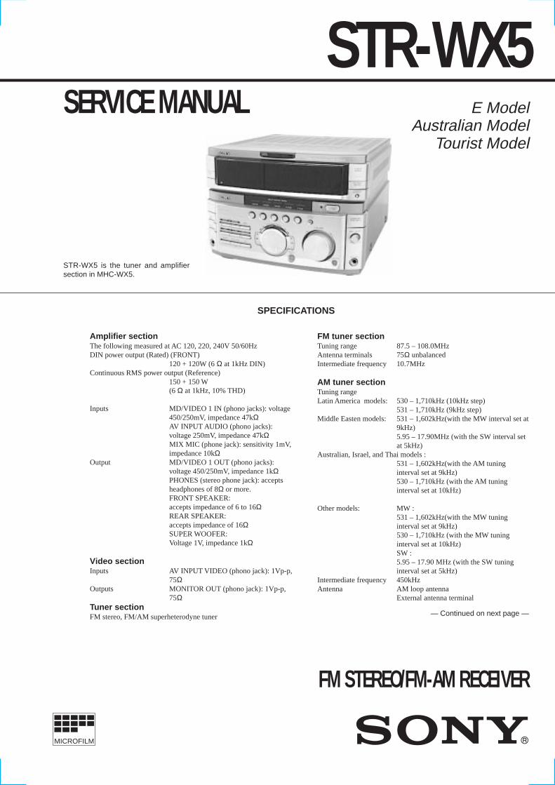
4-4. SCHEMATIC DIAGRAM MAIN(1/2) SECTION • Refer to page 24 for IC Block Diagrams.
(Page 15)
(Page 14) (Page 14) (Page 14) (Page 14)
(Page 18)
16

STR-WX5
1414
4-5. SCHEMATIC DIARGAM MAIN(2/2) SECTION • Refer to page 12 for Printed Wiring Board. • Refer to page 24 for IC Block Diagrams.
The components identified by mark ! or dottedline with mark ! are critical for safety.Replace only with part number specified.
(Page 20)
(Page 23) (Page 15) (Page 20) (Page 16)
(Page 16)
(Page 16)
(Page 13)(Page 13)(Page 13)(Page 13)
16
0.8
0.1
Q854BN1F4M
Q8552SC2958LRELAY SWITCH
R85722k
0

STR-WX5
1515
4-6. SCHEMATIC DIAGRAM AV/MIC SECTION 4-7. PRINTED WIRING BOARD AV/MIC SECTION• Refer to page 24 for IC Block Diagrams. • Refer to page 9 for Circuit Boards Location.
(Page 14)
(Page 18)
(Page 13)
(Page 16)16
MODEL
MODEL
MODEL
MODEL(Page 12)
(Page 12)
(Page 19)
(Page 17)
16
16
4
MODEL
MODEL
MODEL
MODEL
4

STR-WX5
1616
4-8. SCHEMATIC DIAGRAM POWER AMP SECTION
The components identified by mark ! or dottedline with mark ! are critical for safety.Replace only with part number specified.
(Page 14)
(Page 14)
(Page 14)
(Page 15)
16
1/4W
1/4W
1/4W
STR-WX5
1818
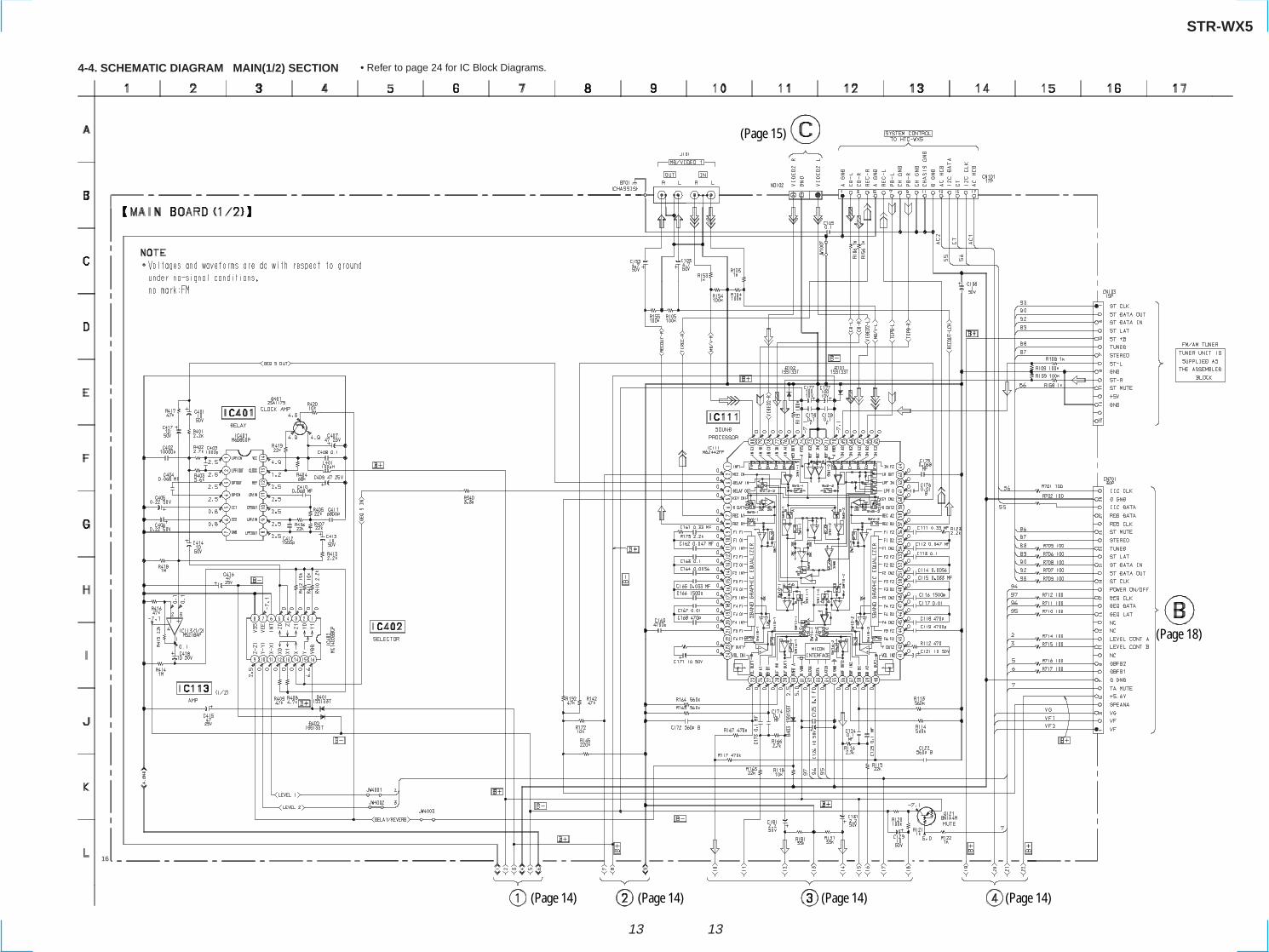
4-10. SCHEMATIC DIAGRAM DISPLAY SECTION • Refer to page 25 for IC Block Diagrams. • Refer to page 26 for IC Pin Function.
(Page 20)
(Page 13) (Page 20)
(Page 15)
16
3.6
3.5
3.5

STR-WX5
2020
4-12. SCHEMATIC DIAGRAM SLIDING PANEL SECTION • Refer to page 28 for IC Block Diagrams.
(Page 18)
(Page 14)
(Page 18)
(Page 14)
0.6
12.7
12.7 0.6
0.7
4.5 0 00
3.6
3.5
16
3.5
3.5
4.9
4.9
4.9
23
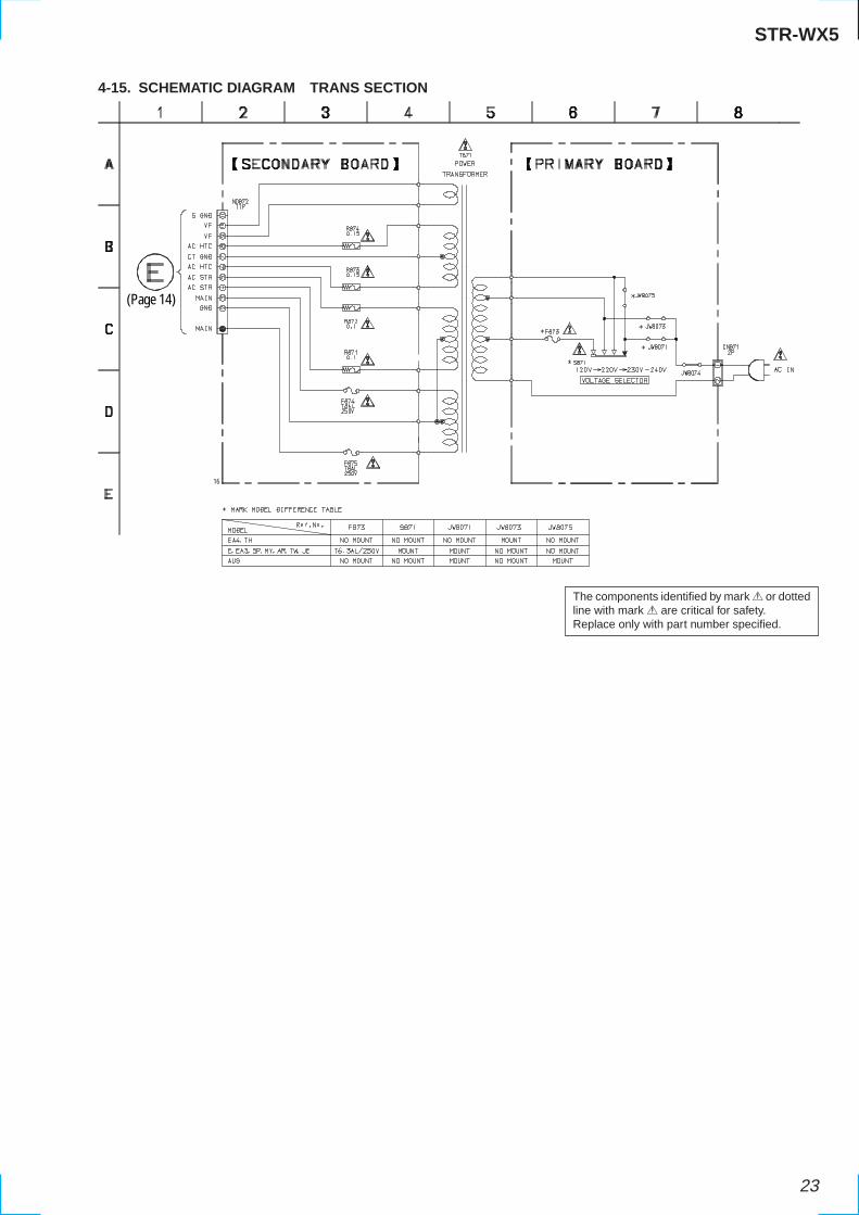
4-15. SCHEMATIC DIAGRAM TRANS SECTION
(Page 14)
16
The components identified by mark ! or dottedline with mark ! are critical for safety.Replace only with part number specified.
STR-WX5

24
• MAIN (2/2) SECTION
IC112 MC14052BCP
1
2
3
4
5
6
7
8
16
15
14
13
12
11
10
9
2X0
X2
VDD
X1
XCOM
X0
X3
A
BVSS
VEE
INH
2X1
2X3
2XCOM
2X2
IC402 MC14053BCP
1
2
3
4
5
6
7
8
B1
B0
C.COM
CO
INH
VEE
VSS
VDD
B.COM
A.COM
A1
A0
A
B
C
C1
9
10
11
12
13
14
15
16
OPEN
OPEN
OPEN
• MAIN (1/2) SECTION
IC401 M65850P
OSCILLATOR
1/2 VCC
AUTORESET
LPF1
MAINCONTROL
A/D
20KBITSRAM
LPF2D/A
1 2 3 4 5 6 7
891014 13 12 11
CLOCK
RESETMO
MID1 DO0
DO1
VCC
CLOC
K
REF
OP2I
N
OP2O
UT
LPF2
IN
LPF2
OUT
LPF1
IN
LPF1
OUT
OP1O
UT
OP1I
N
CC1
CC2
GND
1 2 3 4 5 6 7 8
OVER LOAD DET
F/FOFFSET DET
LATCH/AUTORESET
VCC ONMUTE
AC OFFDET
VCC
IC851 uPC1237HA
• MIC/ECHO SECTION
IC6002 M65850P
OSCILLATOR
1/2 VCC
AUTORESET
LPF1
MAINCONTROL
A/D
20KBITSRAM
LPF2D/A
1 2 3 4 5 6 7
891014 13 12 11
CLOCK
RESETMO
MID1 DO0
DO1
VCC
CLOC
K
REF
OP2I
N
OP2O
UT
LPF2
IN
LPF2
OUT
LPF1
IN
LPF1
OUT
OP1O
UT
OP1I
N
CC1
CC2
GND
4-16. IC BLOCK DIAGRAMS
25
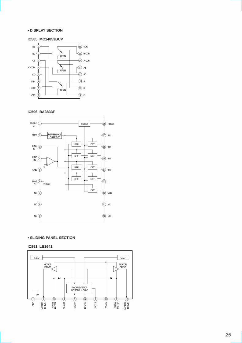
• DISPLAY SECTION
IC505 MC14053BCP
2
3
14
1
f04
13 f
12 VCC
11 NC
10 NC
15 f03
5GND
6BIASC
7NC
8NC
9NC
4
16 f02
17 f01
18 RESETRESETC
PREF
LINENF
LINEIN
REFFERENCECURRENT
BPF DET
BPF DET
BPF DET
BPF DET
DET
RESET
Bias
1
2
3
4
5
6
7
8
B1
B0
C.COM
CO
INH
VEE
VSS
VDD
B.COM
A.COM
A1
A0
A
B
C
C1
9
10
11
12
13
14
15
16
OPEN
OPEN
OPEN
• SLIDING PANEL SECTION
IC891 LB1641
IC506 BA3833F
1 2 3 4 5 6 7 8 9 10
GND
MOT
ORDR
IVE
NOIS
EFI
LTER
CLAM
P
FWD.
IN
REV.
IN
VCC
1
VCC
2
NOIS
EFI
LTER
MOT
ORDR
IVE
MOTORDRIVE
MOTORDRIVE
T.S.D O.C.P
FWD/REV/STOPCONTROL LOGIC
Related Documents