Toll Free 1-888-TDWmSon (839-6766) STOPPLE ® Fittings are full-branch split tees designed for use with TDW plugging machines. The design has undergone extensive strain-gauge and pulsation testing. The average cyclic lives of the fittings are 30% greater than other designs tested. STOPPLE Fittings are furnished with LOCK-O-RING ® Flanges drilled and faced to match ASME Class 150, 300, or 600 flanges. Other ASME Class ratings are available upon request. These reduced branch, split tee fittings are furnished with LOCK-O-RING Flanges for use as bypass fittings. Factory welding of TDW STOPPLE fittings is 100% radiographically inspected at all TDW manufacturing plants except Nivelles, Belgium, where 100% ultasonic examination is used. * 22”, 26”, 28” are Type C Description Features Option STOPPLE ® Fitting Type C (Welded Branch)* Sizes 32” and larger Reducing Branch Fitting ISO 9001 Certified Tapping Machine Typical Tapping Setup For Plugging Operation Bleeder Valve SANDWICH ® Valve STOPPLE ® Fitting Pipeline Equalization Connection Equalization Connection Housing STOPPLE ® Fitting Type B (Extruded Branch) Sizes 4” through 30” Bulletin No: 1100.001.05 Date: July 2008 Cross Indexing No: n/a Supersedes: 1100.001.04 (07/06) STOPPLE ® Fittings & Reduced Branch Split Tees, Sizes 4-inch and Larger T.D. Williamson, Inc. P.O. Box 3409 Tulsa, Oklahoma 74101-3409 918-447-5100 Fax: 918-446-6327 www.tdwilliamson.com Data subject to change without notice. / Dimensions not for construction unless certified. / ® Registered trademark of T.D. Williamson, Inc. in the United States and foreign countries / TM Trademark of T.D. Williamson, Inc. in the United States and foreign countries / © Copyright 2008. All rights reserved T.D. Williamson, Inc. / Printed in USA

Welcome message from author
This document is posted to help you gain knowledge. Please leave a comment to let me know what you think about it! Share it to your friends and learn new things together.
Transcript

Toll Free
1-888-TDWmSon (839-6766)
STOPPLE® Fittings are full-branch split tees designed for use with TDW plugging machines. The design has undergone extensive strain-gauge and pulsation testing. The average cyclic lives of the fittings are 30% greater than other designs tested. STOPPLE Fittings are furnished with LOCK-O-RING® Flanges drilled and faced to match ASME Class 150, 300, or 600 flanges. Other ASME Class ratings are available upon request.
These reduced branch, split tee fittings are furnished with LOCK-O-RING Flanges for use as bypass fittings.
Factory welding of TDW STOPPLE fittings is 100% radiographically inspected at all TDW manufacturing plants except Nivelles, Belgium, where 100% ultasonic examination is used.
* 22”, 26”, 28” are Type C
Description Features
Option
STOPPLE® Fitting Type C (Welded Branch)* Sizes 32” and larger
Reducing Branch Fitting
ISO 9001 Certified
Tapping Machine
Typical Tapping Setup For Plugging Operation
Bleeder Valve
SANDWICH® Valve
STOPPLE® Fitting
Pipeline
Equalization Connection
Equalization Connection
Housing
STOPPLE® Fitting Type B (Extruded Branch) Sizes 4” through 30”
Bulletin No: 1100.001.05Date: July 2008Cross Indexing No: n/aSupersedes: 1100.001.04 (07/06)
STOPPLE® Fittings& Reduced Branch Split Tees, Sizes 4-inch and Larger
T.D. Williamson, Inc. P.O. Box 3409 Tulsa, Oklahoma 74101-3409 918-447-5100 Fax: 918-446-6327 www.tdwilliamson.comData subject to change without notice. / Dimensions not for construction unless certified. / ® Registered trademark of T.D. Williamson, Inc. in the United States and foreign countries / TM Trademark of T.D. Williamson, Inc. in the United States and foreign countries / © Copyright 2008. All rights reserved T.D. Williamson, Inc. / Printed in USA

Dimensions and Part Numbers
Class 150 Maximum allowable operating pressure (in psi) per ASME B31.8 at -20 to +100º F Design factor Inches1 DN Lbs. Kg. 0.72 0.6 0.5 0.4 Part Number 14 350 400 182 285 285 285 285 06-8807-1415 14 350 400 182 285 285 285 285 36-1043-1415-X12
14 350 400 182 285 285 285 285 36-1045-1415-X13
18 450 760 345 285 285 285 285 36-1043-1815-X12
18 450 760 345 285 285 285 285 36-1045-1815-X13
20 500 1000 454 285 285 262 285 36-1043-2015-X12
20 500 1000 454 285 285 262 285 36-1045-2015-X13
22 550 940 426 285 285 285 238 06-8807-2215 24 600 1605 728 285 279 233 186 06-8807-2415 26 650 1340 608 285 285 285 259 06-8807-2615 28 700 1465 665 285 285 250 200 06-8807-2815 30 750 2895 1303 285 285 285 248 06-8807-3015 34 850 2320 1044 285 285 258 206 06-8807-3415 36 900 2780 1251 285 285 239 191 06-8807-3615 40 1000 -- -- -- -- -- -- --4
42 1050 -- -- -- -- -- -- --4
48 1200 -- -- -- -- -- -- --4
1. For sizes 4- through 12-inch and 16-inch sizes, see bulletins 1100.005.01 and 1100.006.01.2. For B31.4 applications. 0.72 and 0.6 Design Factor only.3. For B31.8 applications4. Consult the factory.
1100.001.05 Pg. 2
Maximum Allowable Operatiing Pressure per ASME B31.4 at -20 to +180º F = 285 psi
STOPPLE ® Fittings
T.D. Williamson, Inc. P.O. Box 3409 Tulsa, Oklahoma 74101-3409 918-447-5100 Fax: 918-446-6327 www.tdwilliamson.comData subject to change without notice. / Dimensions not for construction unless certified. / ® Registered trademark of T.D. Williamson, Inc. in the United States and foreign countries / TM Trademark of T.D. Williamson, Inc. in the United States and foreign countries / © Copyright 2008. All rights reserved T.D. Williamson, Inc. / Printed in USA
Class 300 Maximum allowable operating pressure (in psi) per ASME B31.8 at -20 to +100º FDesign Factor
Inches1 DN Lbs. Kg. 0.72 0.6 0.5 0.4 Part Number14 350 400 182 740 740 720 575 36-1043-1430-X12
14 350 400 182 740 740 720 575 36-1045-1430-X13
18 450 780 354 740 710 595 475 36-1043-1830-X12
18 450 780 354 740 710 595 475 36-1045-1830-X13
20 500 1050 477 740 630 525 420 36-1043-2030-X12
20 500 1050 477 740 630 525 420 36-1045-2030-X13
22 550 975 442 740 641 534 427 06-8807-223024 600 1690 767 740 740 627 502 06-8807-243026 650 1540 699 740 740 646 517 06-8807-263028 700 1950 885 740 625 520 415 06-8807-283030 750 2985 1343 740 740 740 672 06-8807-303034 850 3065 1379 740 685 570 455 06-8807-343036 900 3780 1701 740 700 580 465 06-8807-363040 1000 -- -- -- -- -- -- --4
42 1050 -- -- -- -- -- -- --4
48 1200 -- -- -- -- -- -- --4
1. For sizes 4- through 12-inch and 16-inch sizes, see bulletins 1100.005.01 and 1100.006.01.2. For B31.4 applications. 0.72 and 0.6 Design Factor only.3. For B31.8 applications4. Consult the factory.
Maximum Allowable Operatiing Pressure per ASME B31.4 at -20 to +180º F = 740 psi

Dimensions and Part Numbers
Class 600 Maximum allowable operating pressure (in psi) per ASME B31.8 at -20 to +100º FDesign Factor
Inches1 DN Lbs. Kg. 0.72 0.6 0.5 0.4 Part Number14 350 470 214 1480 1230 1025 820 36-1043-1460-X12
14 350 470 214 1480 1230 1025 820 36-1045-1460-X13
18 450 900 409 1480 1300 1080 865 36-1043-1860-X12
18 450 900 409 1480 1300 1080 865 36-1045-1860-X13
20 500 1200 545 1480 1320 1100 880 36-1043-2060-X12
20 500 1200 545 1480 1320 1100 880 36-1045-2060-X13
22 550 1725 782 1480 1480 1235 985 06-8807-2260 24 600 1895 860 1480 1335 1125 900 06-8807-2460 26 650 2070 932 1480 1245 1035 830 06-8807-2660 28 700 2730 1238 1480 1270 1060 845 06-8807-2860 30 750 3180 1431 1480 1255 1045 835 06-8808-3060 34 850 4640 2088 1480 1372 1143 914 06-8807-3460 36 900 5990 2696 1480 1335 1110 890 06-8807-3660 40 1000 6705 3041 1480 1315 1095 875 06-8807-4060 42 1050 7650 3470 1480 1265 1050 840 06-8807-4260 48 1200 -- -- -- -- -- -- --4
1. For sizes 4- through 12-inch and 16-inch sizes, see bulletins 1100.005.01 and 1100.006.01.2. For B31.4 applications. 0.72 and 0.6 Design Factor only.3. For B31.8 applications4. Consult the factory.
Reducing Branch Split Tees (Hot Drawn) with LOCK-O-RING® Flanges
Class 600 Maximum allowable operating pressure (in psi) per ASME B31.8 at -20 to +100º F Size Dimension L Dimension H Weight Design Factor Inches DN Inches mm Inches mm Lbs. Kg. Part Number 0.72 0.60 0.50 0.40 6 x 4 150 x 100 10.750 273 8.375 213 75 34 06-8812-0604 1480 1480 1295 1035 8 x 4 200 x 100 10.750 273 9.375 238 80 36 06-8812-0804 1480 1235 1030 825 10 x 6 250 x 150 14.000 356 11.250 286 140 64 06-8812-1006 1480 1305 1085 870 12 x 6 300 x 150 14.000 356 12.438 316 170 77 06-8812-1206 1480 1260 1050 840 14 x 8 350 x 200 16.500 419 13.688 348 245 111 06-8812-1408 1480 1230 1025 820 16 x 12 400 x 300 24.000 610 15.938 405 485 220 06-8812-1612 1480 1270 1058 847 20 x 12 500 x 300 24.000 610 18.312 465 605 274 06-8812-2012 1480 1270 1058 847
Reducing Branch Fitting
L
H
1100.001.05 Pg. 3
Maximum Allowable Operatiing Pressure per ASME B31.4 at -20 to +180º F = 1480 psi
STOPPLE ® Fittings & Reduced Branch Split Tees
T.D. Williamson, Inc. P.O. Box 3409 Tulsa, Oklahoma 74101-3409 918-447-5100 Fax: 918-446-6327 www.tdwilliamson.comData subject to change without notice. / Dimensions not for construction unless certified. / ® Registered trademark of T.D. Williamson, Inc. in the United States and foreign countries / TM Trademark of T.D. Williamson, Inc. in the United States and foreign countries / © Copyright 2008. All rights reserved T.D. Williamson, Inc. / Printed in USA

Dimensions
NOTE: Flanges in sizes 10” (250 mm) and below are drilled and faced according to ANSI B16.5. Flanges above 10” (250 mm) are drilled and faced according to MSS-SP44. When ordering replacement fittings, please specify fitting equipped with flanges which will fit existing hot tap or STOPPLE® equipment.
1 Class 600 50.00 (1270)
Type B: Hot-drawn, full-branch opening, snug-fitting sleeve and a LOCK-O-RING® Flange of the desired series.
Type C: Fabricated full-size nipple, branch outlet welded to snug-fitting sleeve and a LOCK-O-RING Flange of the desired series.
Reducing-Branch Split Tee: Hot-drawn, reduced-branch opening, snug-fitting sleeve and a LOCK-O-RING Flange or standard weld-neck flange of the desired series.
Standard cataloged Class 600 STOPPLE® fittings and Class 600 reduced-branch fittings are designed for working pressure of 1480 psi (102 bar) with a design factor F of .72 per ASME B31.8-1995 and B31.4-1992. Consult the factory for fittings for other applications or design factors.
Description of Fittings
L
H
Type B
L
H
Type C
Size L (All Series) H (Class 150) H (Class 300) H (Class 600) Inches DN Type Inches mm Inches mm Inches mm Inches mm 14 350 B 26.000 660 13.922 354 13.922 354 14.922 380 18 450 B 33.000 838 17.546 446 17.546 446 17.922 456 20 500 B 36.000 914 19.046 484 19.046 484 20.172 513 22 550 C 40.000 1016 19.125 477 20.312 507 21.312 532 24 600 B 43.000 1092 20.500 512 21.938 547 22.375 557 26 650 C 1 47.000 1194 21.250 530 22.500 562 25.750 642 28 700 C 49.000 1245 22.688 565 23.812 595 25.812 645 30 750 B 56.000 1423 24.562 612 25.000 632 27.234 692 34 850 C 61.000 1541 27.188 677 27.750 692 30.438 760 36 900 C 65.000 1651 28.438 710 29.062 725 31.125 777 40 1000 C -- -- -- -- -- -- -- -- 42 1050 C -- -- -- -- -- -- -- -- 48 1200 C -- -- -- -- -- -- -- --
Dimensions and Part Numbers
1100.001.05 - p4
STOPPLE ® Fittings
T.D. Williamson, Inc. P.O. Box 3409 Tulsa, Oklahoma 74101-3409 918-447-5100 Fax: 918-446-6327 www.tdwilliamson.comData subject to change without notice. / Dimensions not for construction unless certified. / ® Registered trademark of T.D. Williamson, Inc. in the United States and foreign countries / TM Trademark of T.D. Williamson, Inc. in the United States and foreign countries / © Copyright 2008. All rights reserved T.D. Williamson, Inc. / Printed in USA

Toll Free
1-888-TDWmSon (839-6766)
ISO 9001 Certified
Tapping Machine
Typical Tapping Setup For Plugging Operation
Bleeder Valve
SANDWICH® Valve
STOPPLE® Fitting
Pipeline
Equalization Connection
Equalization Connection
Housing
Bulletin No: 1100.004.01Date: November 2008Cross Indexing No: n/aSupersedes: January 2008
STOPPLE® FittingsASME B31.3 - Sizes 4- through 12- & 16-inch
T.D. Williamson, Inc. P.O. Box 3409 Tulsa, Oklahoma 74101-3409 918-447-5100 Fax: 918-446-6327 www.tdwilliamson.comData subject to change without notice. / Dimensions not for construction unless certified. / ® Registered trademark of T.D. Williamson, Inc. in the United States and foreign countries / TM Trademark of T.D. Williamson, Inc. in the United States and foreign countries / © Copyright 2008. All rights reserved T.D. Williamson, Inc. / Printed in USA
STOPPLE® Fittings are 4- through 12- & 16-inch full-branch split tees designed for use with the TDW STOPPLE plugging system. They meet B31.3 specifications for use in refinery and chemical plant piping systems. STOPPLE Fittings are furnished with LOCK-O-RING® Flanges to accept a LOCK-O-RING Completion Plug, permitting removal of the tapping valve after work is completed.
Description
STOPPLE® FittingLOCK-O-RING® Plug, Blind flange, studs, nuts and gasket sold separately
All pressure-containing welds on the fittings have undergone X-ray inspection per ASME requirements.
Fitting sleeves are an extruded type design. They are manufactured from a pressure-vessel quality, normalized, killed carbon steel plate with hardness below Rc22.
The Charpy impact value of the sleeves at -50°F is 15 ft-lbs average with 12 ft-lbs minimum.
Flange-to-sleeve weld joints and sleeves are designed to meet pressure and reinforcement requirements of ASME codes, and are available in Class 150, 300 and 600. Other ASME Class ratings available upon request.
Fittings are manufactured with a controlled carbon equivalent to make welding easier in harsh environments. Back-up strips are provided for all fittings.
Features Rapid delivery: If the desired fitting
meets standard specifications, it can be shipped from stock or within two weeks in most cases.
Choice of flanges.
Available also to ASME B31.4 and B31.8 specifications
Use the grid inside to develop the part number for the STOPPLE fitting of your choice*Contact the factory for information concerning ordering of split sleeves (tees). *Please confirm your choice with a Factory Representative
Options
New fittings incorporate a designed and manufactured offset allowing the placement of back-up strips
Offset in closeup

Dimensions and Part Numbers
1100.004.01 Pg. 2
T.D. Williamson, Inc. P.O. Box 3409 Tulsa, Oklahoma 74101-3409 918-447-5100 Fax: 918-446-6327 www.tdwilliamson.comData subject to change without notice. / Dimensions not for construction unless certified. / ® Registered trademark of T.D. Williamson, Inc. in the United States and foreign countries / TM Trademark of T.D. Williamson, Inc. in the United States and foreign countries / © Copyright 2008. All rights reserved T.D. Williamson, Inc. / Printed in USA
3 6 - 1 0 4 1 - X X X X - X XExample
36-1041-0630-11 is a STOPPLE® Fitting with 6” (run) x 6” (branch), with an RF standard weight flange, A105 TDW std. flange material, BUNA-N o-rings, class 300, and A 537 CL. 1 TDW Std. sleeve material with back-up strips.
Fitting Weights and Pressure Ratings
Size Weight (lbs.) Weight (lbs.) Weight (lbs.) MAOP (in psi) @ -20 to 100°F Inches (Nom.) Class 150 Class 300 Class 600 Class 150 Class 300 Class 600 04 55 60 65 285 740 1480 06 90 100 105 285 740 1145 08 135 140 160 285 740 915 10 190 190 280 285 740 965 12 300 300 380 285 740 930 16 580 600 700 285 740 965
Consult factory for other pressure and temperature requirements
Flange and O-Ring Material
Option Flange/O-Ring Material O-Ring Temp Ratings 1X A105 w/ Buna-N O-Rings 212º F 2X A694 F46 w/ Buna-N O-Rings (See Note) 3X A105 w/ NEOPRENE O-Rings 225º F 4X A694 F46 w/ NEOPRENE O-Rings (See Note) 5X A105 w/ VITON O-Rings 400º F 6X A694 F46 w/ VITON O-Rings (See Note) 7X A105 w/ EPDM O-Rings 250º F / 500º F Steam 8X A694 F46 w/ EPDM O-Rings (See Note)
Sleeve Material
Option Sleeve Material X1 A537 CL1 X2 A516 GR 70
STOPPLE® Fitting ASME Class
Part Number Option 15 150 LB 30 300 LB 60 600 LB
STOPPLE® Fitting Size
Inches Dim. H (Inches) Dim. L Dim D (Nom.) Class 150 Class 300 Class 600 Inches Inches 04 7.015 7.015 7.266 10.75 4.656 06 8.828 8.828 9.078 14.00 6.781 08 10.156 10.156 10.406 16.50 8.812 10 11.218 11.218 12.844 20.00 10.938 12 12.406 12.906 13.922 22.00 12.968 16 16.172 16.172 16.546 30.00 16.218
L
H
D
STOPPLE ® Fittings - ASME B31.3
Note: Standard flange material for 4- through 12-inch is A105, 16-inch is A694 F46.Viton® is a registered trademarks of DuPont Performance Elastomers LLC Ltd

Dimensions and Part Numbers
1100.004.01 Pg. 3
T.D. Williamson, Inc. P.O. Box 3409 Tulsa, Oklahoma 74101-3409 918-447-5100 Fax: 918-446-6327 www.tdwilliamson.comData subject to change without notice. / Dimensions not for construction unless certified. / ® Registered trademark of T.D. Williamson, Inc. in the United States and foreign countries / TM Trademark of T.D. Williamson, Inc. in the United States and foreign countries / © Copyright 2008. All rights reserved T.D. Williamson, Inc. / Printed in USA
STOPPLE ® Fittings - ASME B31.3
-20/100 200 300 400 500 600 700Temperature - ºF
Pres
sure
- PS
I
285260230200170140
110
4-, 6- and 8-inch 150 LB A105 Flange and A537 CL1 or A516 GR 70 Sleeve
Pressure and Temperature Ratings
-20/100 200 300 400 500 600 700Temperature - ºF
Pres
sure
- PS
I
1480
1360131012651205
1135
1060
4-inch 600 LB A105 Flange and A537 CL1 or A516 GR 70 Sleeve
-20/100 200 300 400 500 600 700Temperature - ºF
Pres
sure
- PS
I
115511351120
1060
6-inch 600 LB A105 Flange and A537 CL1 Sleeve
-20/100 200 300 400 500 600 700Temperature - ºF
Pres
sure
- PS
I
115511451115
1075
1015
925905
6-inch 600 LB A105 Flange and A516 GR 70 Sleeve
-20/100 200 300 400 500 600 700Temperature - ºF
Pres
sure
- PS
I
740
680655635605
570
530
4-, 6- and 8-inch 300 LB A105 Flange and A537 CL1 or A516 GR 70 Sleeve
NOTE: The pressure/temperatue ratings in the charts only apply after pipe plugs and blind flange have been installed. (See O-Ring Temperature ratings on page 2)

-20/100 200 300 400 500 600 700Temperature - ºF
Pres
sure
- PS
I
285260230200170140
110
10-, 12- and 16-inch 150 LB A105 Flange and A537 CL1 or A516 GR 70 Sleeve
-20/100 200 300 400 500 600 700Temperature - ºF
Pres
sure
- PS
I740
680655635605
570
530
10-, 12- and 16-inch 300 LB A105 Flange and A537 CL1 or A516 GR 70 Sleeve
1100.004.01 Pg. 4
T.D. Williamson, Inc. P.O. Box 3409 Tulsa, Oklahoma 74101-3409 918-447-5100 Fax: 918-446-6327 www.tdwilliamson.comData subject to change without notice. / Dimensions not for construction unless certified. / ® Registered trademark of T.D. Williamson, Inc. in the United States and foreign countries / TM Trademark of T.D. Williamson, Inc. in the United States and foreign countries / © Copyright 2008. All rights reserved T.D. Williamson, Inc. / Printed in USA
Dimensions and Part Numbers
STOPPLE ® Fittings - ASME B31.3
Pressure and Temperature Ratings
NOTE: The pressure/temperatue ratings in the charts only apply after pipe plugs and blind flange have been installed. (See O-Ring Temperature ratings on page 2)
-20/100 200 300 400 500 600 700Temperature - ºF
Pres
sure
- PS
I
915900890
840
8-inch 600 LB A105 Flange and A537 CL1 Sleeve
-20/100 200 300 400 500 600 700Temperature - ºF
Pres
sure
- PS
I
915910885855
805
735720
8-inch 600 LB A105 Flange and A516 GR 70 Sleeve
-20/100 200 300 400 500 600 700Temperature - ºF
Pres
sure
- PS
I
965955930900
850
775755
10-inch 600 LB A105 Flange and A516 GR 70 Sleeve
-20/100 200 300 400 500 600 700Temperature - ºF
Pres
sure
- PS
I
965950935
885
10-inch 600 LB A105 Flange and A537 CL1 Sleeve

-20/100 200 300 400 500 600 700Temperature - ºF
Pres
sure
- PS
I
930925900870
820
750730
12-inch 600 LB A105 Flange and A516 GR 70 Sleeve
-20/100 200 300 400 500 600 700Temperature - ºF
Pres
sure
- PS
I
930915905
855
12-inch 600 LB A105 Flange and A537 CL1 Sleeve
1100.004.01 Pg. 5
T.D. Williamson, Inc. P.O. Box 3409 Tulsa, Oklahoma 74101-3409 918-447-5100 Fax: 918-446-6327 www.tdwilliamson.comData subject to change without notice. / Dimensions not for construction unless certified. / ® Registered trademark of T.D. Williamson, Inc. in the United States and foreign countries / TM Trademark of T.D. Williamson, Inc. in the United States and foreign countries / © Copyright 2008. All rights reserved T.D. Williamson, Inc. / Printed in USA
Dimensions and Part Numbers
STOPPLE ® Fittings - ASME B31.3
Pressure and Temperature Ratings
NOTE: The pressure/temperatue ratings in the charts only apply after pipe plugs and blind flange have been installed. (See O-Ring Temperature ratings on page 2)
16-inch 600 LB A105 Flange and A537 CL1 Sleeve
-20/100 200 300 400 500 600 700Temperature - ºF
Pres
sure
- PS
I
965950935
885
16-inch 600 LB A105 Flange and A516 GR 70 Sleeve
-20/100 200 300 400 500 600 700Temperature - ºF
Pres
sure
- PS
I
965955930900
850
775755

Toll Free
1-888-TDWmSon (839-6766)
ISO 9001 Certified
Tapping Machine
Typical Tapping Setup For Plugging Operation
Bleeder Valve
SANDWICH® Valve
STOPPLE® Fitting
Pipeline
Equalization Connection
Equalization Connection
Housing
Bulletin No: 1100.005.01Date: November 2008Cross Indexing No: n/aSupersedes: October 2007
STOPPLE® FittingsASME B31.4 - Sizes 4- through 12- & 16-inch
T.D. Williamson, Inc. P.O. Box 3409 Tulsa, Oklahoma 74101-3409 918-447-5100 Fax: 918-446-6327 www.tdwilliamson.comData subject to change without notice. / Dimensions not for construction unless certified. / ® Registered trademark of T.D. Williamson, Inc. in the United States and foreign countries / TM Trademark of T.D. Williamson, Inc. in the United States and foreign countries / © Copyright 2008. All rights reserved T.D. Williamson, Inc. / Printed in USA
STOPPLE® Fittings are 4- through 12-inch & 16-inch full-branch split tees designed for use with the TDW STOPPLE plugging system. They meet B31.4 specifications for use in pipeline transportation systems for liquid hydrocarbons and other liquids. STOPPLE Fittings are furnished with LOCK-O-RING® Flanges to accept a LOCK-O-RING Completion Plug, permitting removal of the tapping valve after work is completed.
DescriptionAll pressure-containing welds on the fittings
have undergone X-ray inspection per ASME requirements.
Fitting sleeves are an extruded type design. They are manufactured from a pressure-vessel quality, normalized, killed carbon steel plate with hardness below Rc22.
The Charpy impact value of the sleeves at -50°F is 15 ft-lbs average with 12 ft-lbs minimum.
Flange-to-sleeve weld joints and sleeves are designed to meet pressure and reinforcement requirements of ASME codes, and are available in Class 150, 300 and 600. Other ASME Class ratings available upon request.
Fittings are manufactured with a controlled carbon equivalent to make welding easier in harsh environments. Back-up strips are provided for all fittings.
Features Rapid delivery: If the desired fitting
meets standard specifications, it can be shipped from stock or within two weeks in most cases.
Choice of flanges.
Available also to ASME B31.3 and B31.8 specifications
Use the grid inside to develop the part number for the STOPPLE fitting of your choice*Contact the factory for information concerning ordering of split sleeves (tees). *Please confirm your choice with a Factory Representative
Options
STOPPLE® FittingLOCK-O-RING® Plug, Blind flange, studs, nuts and gasket sold separately
New fittings incorporate a designed and manufactured offset allowing the placement of back-up strips
Offset in closeup
Dimensions and Part Numbers
1100.005.01 Pg. 2STOPPLE ® Fittings - ASME B31.4
T.D. Williamson, Inc. P.O. Box 3409 Tulsa, Oklahoma 74101-3409 918-447-5100 Fax: 918-446-6327 www.tdwilliamson.comData subject to change without notice. / Dimensions not for construction unless certified. / ® Registered trademark of T.D. Williamson, Inc. in the United States and foreign countries / TM Trademark of T.D. Williamson, Inc. in the United States and foreign countries / © Copyright 2008. All rights reserved T.D. Williamson, Inc. / Printed in USA
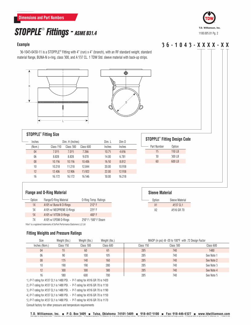
3 6 - 1 0 4 3 - X X X X - X XExample
36-1043-0430-11 is a STOPPLE® Fitting with 4” (run) x 4” (branch), with an RF standard weight, standard material flange, BUNA-N o-ring, class 300, and A 537 CL. 1 TDW Std. sleeve material with back-up strips.
Fitting Weights and Pressure Ratings
Size Weight (lbs.) Weight (lbs.) Weight (lbs.) MAOP (in psi) @ -20 to 100°F with .72 Design Factor Inches (Nom.) Class 150 Class 300 Class 600 Class 150 Class 300 Class 600 04 55 60 65 285 740 1480 06 90 100 105 285 740 See Note 1 08 135 140 160 285 740 See Note 2 10 190 190 280 285 740 See Note 3 12 300 300 380 285 740 See Note 4 16 580 600 700 285 740 See Note 51.) P-T rating for A537 CL1 is 1480 PSI. - P-T rating for A516 GR 70 is 14202.) P-T rating for A537 CL1 is 1480 PSI. - P-T rating for A516 GR 70 is 11303.) P-T rating for A537 CL1 is 1480 PSI. - P-T rating for A516 GR 70 is 11904.) P-T rating for A537 CL1 is 1480 PSI. - P-T rating for A516 GR 70 is 11505.) P-T rating for A537 CL1 is 1480 PSI. - P-T rating for A516 GR 70 is 1170Consult factory for other pressure and temperature requirements
Sleeve Material
Option Sleeve Material X1 A537 CL1 X2 A516 GR 70
STOPPLE® Fitting Design Code
Part Number Option 15 150 LB 30 300 LB 60 600 LB
STOPPLE® Fitting Size
Inches Dim. H (Inches) Dim. L Dim D (Nom.) Class 150 Class 300 Class 600 Inches Inches 04 7.015 7.015 7.266 10.75 4.656 06 8.828 8.828 9.078 14.00 6.781 08 10.156 10.156 10.406 16.50 8.812 10 10.218 11.218 12.844 20.00 10.938 12 12.406 12.906 13.922 22.00 12.938 16 16.172 16.172 16.546 30.00 16.218
L
H
D
Flange and O-Ring Material
Option Flange/O-Ring Material O-Ring Temp. Ratings 1X A105 w/ Buna-N O-Rings 212º F 3X A105 w/ NEOPRENE O-Rings 225º F 5X A105 w/ VITON O-Rings 400º F 7X A105 w/ EPDM O-Rings 250º F / 500º F SteamViton® is a registered trademarks of DuPont Performance Elastomers LLC Ltd

Toll Free
1-888-TDWmSon (839-6766)
ISO 9001 Certified
Tapping Machine
Typical Tapping Setup For Plugging Operation
Bleeder Valve
SANDWICH® Valve
STOPPLE® Fitting
Pipeline
Equalization Connection
Equalization Connection
Housing
Bulletin No: 1100.006.01Date: November 2008Cross Indexing No: n/aSupersedes: October 2007
STOPPLE® FittingsASME B31.8 - Sizes 4- through 12-inch & 16-inch
T.D. Williamson, Inc. P.O. Box 3409 Tulsa, Oklahoma 74101-3409 918-447-5100 Fax: 918-446-6327 www.tdwilliamson.comData subject to change without notice. / Dimensions not for construction unless certified. / ® Registered trademark of T.D. Williamson, Inc. in the United States and foreign countries / TM Trademark of T.D. Williamson, Inc. in the United States and foreign countries / © Copyright 2008. All rights reserved T.D. Williamson, Inc. / Printed in USA
STOPPLE® Fittings are 4- through 12-inch & 16-inch full-branch split tees designed for use with the TDW STOPPLE plugging system. They meet B31.8 specifications for gas transmission and distribution piping systems. STOPPLE Fittings are furnished with LOCK-O-RING® Flanges to accept a LOCK-O-RING Completion Plug, permitting removal of the tapping valve after work is completed.
DescriptionAll pressure-containing welds on the fittings
have undergone X-ray inspection per ASME requirements.
Fitting sleeves are an extruded type design. They are manufactured from a pressure-vessel quality, normalized, killed carbon steel plate with hardness below Rc22.
The Charpy impact value of the sleeves at -50°F is 15 ft-lbs average with 12 ft-lbs minimum.
Flange-to-sleeve weld joints and sleeves are designed to meet pressure and reinforcement requirements of ASME codes, and are available in Class 150, 300 and 600. Other ASME Class ratings available upon request.
Fittings are manufactured with a controlled carbon equivalent to make welding easier in harsh environments. Back-up strips are provided for all fittings.
Features Rapid delivery: If the desired fitting
meets standard specifications, it can be shipped from stock or within two weeks in most cases.
Choice of flanges.
Available also to ASME B31.3 and B31.4 specifications
Use the grid inside to develop the part number for the STOPPLE fitting of your choice*Contact the factory for information concerning ordering of split sleeves (tees). *Please confirm your choice with a Factory Representative
Options
STOPPLE® FittingLOCK-O-RING® Plug, Blind flange, studs, nuts and gasket sold separately
New fittings incorporate a designed and manufactured offset allowing the placement of back-up strips
Offset in closeup

3 6 - 1 0 4 5 - X X X X - X XExample
36-1045-0430-11 is a STOPPLE® Fitting with 4” (run) x 4” (branch), with an RF standard weight, standard material flange, BUNA-N o-ring, class 300, and A 537 CL. 1 TDW Std. sleeve material with back-up strips.
Dimensions and Part Numbers
1100.006.01 Pg. 2
T.D. Williamson, Inc. P.O. Box 3409 Tulsa, Oklahoma 74101-3409 918-447-5100 Fax: 918-446-6327 www.tdwilliamson.comData subject to change without notice. / Dimensions not for construction unless certified. / ® Registered trademark of T.D. Williamson, Inc. in the United States and foreign countries / TM Trademark of T.D. Williamson, Inc. in the United States and foreign countries / © Copyright 2008. All rights reserved T.D. Williamson, Inc. / Printed in USA
STOPPLE ® Fittings - ASME B31.8
Sleeve Material
Option Sleeve Material X1 A537 CL1 X2 A516 GR 70
STOPPLE® Fitting ASME Class
Part Number Option 15 150 LB 30 300 LB 60 600 LB
STOPPLE® Fitting Size
Inches Dim. H (Inches) Dim. L Dim D (Nom.) Class 150 Class 300 Class 600 Inches Inches 04 7.015 7.015 7.266 10.75 4.656 06 8.828 8.828 9.078 14.00 6.781 08 10.156 10.156 10.406 16.50 8.812 10 10.218 11.218 12.844 20.00 10.938 12 12.406 12.906 13.922 22.00 12.938 16 16.172 16.172 16.546 30.00 16.218
L
H
D
Fitting Weights
Size Weight (lbs.) Weight (lbs.) Weight (lbs.) Inches (Nom.) Class 150 Class 300 Class 600 04 55 60 65 06 90 100 105 08 135 140 160 10 190 190 280 12 300 300 380 16 580 600 700
Flange and O-Ring Material
Option Flange/O-Ring Material O-Ring Temp. Ratings 1X A105 w/ Buna-N O-Rings 212º F 2X A694 F46 w/ Buna-N O-Rings (See Note) 3X A105 w/ NEOPRENE O-Rings 225º F 4X A694 F46 w/ NEOPRENE O-Rings (See Note) 5X A105 w/ VITON O-Rings 400º F 6X A694 F46 w/ VITON O-Rings (See Note) 7X A105 w/ EPDM O-Rings 250º F / 500º F Steam 8X A694 F46 w/ EPDM O-Rings (See Note)Note: Only 16-inch flange is available in A694 F46.Viton® is a registered trademarks of DuPont Performance Elastomers LLC Ltd

Maximum Allowable Operating Pressure (in psi) -20˚F to 100˚F
.72 Design Factor .6 Design Factor .5 Design Factor .4 Design Factor Class Size A516 GR 70N A537 CL 1 A516 GR 70N A537 CL 1 A516 GR 70N A537 CL 1 A516 GR 70N A537 CL 1 150 4 285 285 285 285 285 285 285 285 6 285 285 285 285 285 285 285 285 8 285 285 285 285 285 285 285 285 10 285 285 285 285 285 285 285 285 12 285 285 285 285 285 285 285 285 16 285 285 285 285 285 285 285 285 300 4 740 740 740 740 740 740 740 740 A 105 Flange 6 740 740 740 740 740 740 650 650 8 740 740 735 735 615 615 490 490 10 740 740 740 740 740 740 625 625 12 740 740 740 740 740 740 615 615 16 740 740 740 740 740 740 640 640 300 16 740 740 740 740 740 740 650 685 A694 F46 Flange 600 4 1480 1480 1480 1480 1380 1480 1105 1205 A 105 Flange 6 1420 1480 1180 1480 985 1295 785 1035 8 1130 1480 940 1235 785 1030 625 825 10 1190 1480 990 1305 825 1085 660 870 12 1150 1480 955 1230 795 1025 635 820 16 1170 1480 975 1285 815 1070 650 855 600 16 1170 1480 975 1285 815 1070 650 855 A694 F46 Flange
Note 1: A694 F46 option is available for 16-inch flange only.Note 2: 16-inch 150 Lb values are the same for A105 and A694 F46 FlangesConsult Factory for other pressure and temperature requirements
Dimensions and Part Numbers
1100.006.01 Pg. 3
T.D. Williamson, Inc. P.O. Box 3409 Tulsa, Oklahoma 74101-3409 918-447-5100 Fax: 918-446-6327 www.tdwilliamson.comData subject to change without notice. / Dimensions not for construction unless certified. / ® Registered trademark of T.D. Williamson, Inc. in the United States and foreign countries / TM Trademark of T.D. Williamson, Inc. in the United States and foreign countries / © Copyright 2008. All rights reserved T.D. Williamson, Inc. / Printed in USA
STOPPLE ® Fittings - ASME B31.8

North & South America: +1 918 447 5000 Europe / Africa / Middle East: +32 67 28 3611 Asia Pacific: +65 6364 8520 www.tdwilliamson.comData subject to change without notice. / Dimensions not for construction unless certified. / ® Registered trademark of T.D. Williamson, Inc. in the United States and other countries. / TM Trademark of T.D. Williamson, Inc. in the United States and other countries. / © Copyright 2014 All rights reserved. T.D. Williamson, Inc.
STOPPLE Plus fittings are manufactured with a controlled carbon equivalent of 0.45 or lower. Factory welding of TDW STOPPLE Plus fittings is 100 percent radiographically inspected. Fitting sleeves are an extruded or fabricated type design, manufactured from a pressure-vessel quality, normalized, killed carbon steel plate with a hardness of Rc22 or lower.
The charpy impact value of 20 ft-lbs average with 15 ft-lbs minimum can be reached at -20ºF for the standard option and at -50ºF for the low- temp option.
LOCK-O-RING Plus plugs are retained in the STOPPLE Plus fittings by means of retaining leaves, mounted on the plug, that are extended into a mating groove in the flange of the fitting.
Features
STOPPLE® Plus fittings are full-branch split tees designed for use with TDW plugging machines. The design has undergone extensive pressure and functional testing. STOPPLE Plus fittings are furnished with LOCK-O-RING® Plus flanges drilled and faced to match ASME Class 150, 300 or 600 flanges in sizes 4- through 36-inches and ASME Class 900 for 4-and 6-inches.
STOPPLE Plus fittings are an alternative to conventional TDW STOPPLE fittings and are designed to ASME B31.3, B31.4 and B31.8 requirements (see chart for MAOP).
There are no side openings in the flange, which reduces potential leak paths.
Interlock system provides positive indication LOCK-O-RING Plus plug leaves are fully extended.
Complete installation and retrieval of LOCK-O-RING Plus plug is done using tapping machine. Setting LOCK-O-RING Plus completion plug takes less time compared to setting completion plugs using other high-pressure setting methods.
Description
STOPPLE ® Plus Fitting
Options
Bulletin No: 1100.007.02Version: 08.2014Cross Indexing No: n/aSupercedes: 1100.007.01 (06.2014)
Standard STOPPLE Plus fittings are furnished in a kit featuring the following components: LOCK-O-RING Plus flange with raised face; matching blind flange, studs, nuts, anti-rotational pin and a stainless steel spiral wound gasket; LOCK-O-RING Plus plug with Buna-N O-ring; scarfed nipple for the LOCK-O-RING Plus plug to replace the coupon cut from pipeline; and tile red primer coating.
Standard STOPPLE Plus fittings incorporate a designed and manufactured offset allowing the placement of backup strips.
Options include:
Neoprene, Viton®, EPDM or Low-Temp Buna-N O-rings.
LOCK-O-RING Plus flange with ring type joint facing for 4- through 14-inch.
Reduced branch variations can be ordered.
Standard Temp/Non-NACE MR 0175 versus Low Temp/NACE MR 0175.
LOCK-O-RING® Plus Plugs
STOPPLE®
Plus FittingsSizes: 4- Through 36-inch
STOPPLE® Plus fittings incorporate a designed and manufactured offset allowing the placement of back-up strips
Offset in closeup
ISO 9001 Certified
Viton® is a registered trademark of DuPont Performance Elastomers.

North & South America: +1 918 447 5000 Europe / Africa / Middle East: +32 67 28 3611 Asia Pacific: +65 6364 8520 www.tdwilliamson.comData subject to change without notice. / Dimensions not for construction unless certified. / ® Registered trademark of T.D. Williamson, Inc. in the United States and other countries. / TM Trademark of T.D. Williamson, Inc. in the United States and other countries. / © Copyright 2014 All rights reserved. T.D. Williamson, Inc.
1100.007.02 - Pg. 2
Dimensions and Part Numbers
STOPPLE ® Plus Fittings
Fitting Kit Material
Option Fitting Kit Material
2 Non-NACE MR 0175/Standard Temp (-20ºF) 3 NACE MR 0175/Low Temp (-50ºF)
Example26-2357-0630-14 is a STOPPLE Plus Fitting kit which includes the following:• A fitting with a 6" run X 6" branch, an ASME Class 300 RF flange, and 2 (loose) longitudinal back-up strips.• A plug with a Buna-N O-ring and a (loose) scarfed nipple.• ASME B31.4 design code compliant.• An ASME class 300 RF blind flange with studs, nuts, gasket and anti-rotation pin.
2 6 - X 3 5 7 - X X X X - X X
Inches Dim CLF (inches) Dim H (inches) Dim L Dim D (Nom) Class 150 Class 300 Class 600 Class 900 Class 150 Class 300 Class 600 Class 900 Inches Inches 04 6.390 6.390 7.015 7.453 10.161 10.473 11.598 12.286 10.75 4.656 06 8.078 8.078 9.078 9.359 12.974 13.412 15.099 15.695 14.00 6.781 08 9.625 9.625 10.750 - 15.661 16.161 18.099 - 16.50 8.812 10 11.218 11.218 12.844 - 18.505 19.192 21.693 - 20.00 10.938 12 12.922 12.922 13.609 - 21.411 22.161 23.723 - 22.00 12.968 14 13.922 13.922 14.453 - 23.161 23.911 25.317 - 26.00 14.218 16 14.640 14.640 15.922 - 25.067 25.879 28.161 - 30.00 16.218 18 16.484 16.484 17.640 - 28.160 28.973 31.254 - 33.00 18.218 20 17.812 17.812 19.328 - 30.739 31.551 34.317 - 36.00 20.218 22 20.141 21.047 20.297 34.3955 36.1145 36.4895 - 40.00 22.125 24 20.922 21.672 21.797 - 36.2395 38.8645 39.2395 - 43.00 24.125 26 22.172 23.922 23.922 - 39.3025 41.6765 43.3025 - 50.00 26.125 28 23.187 25.094 24.969 - 40.879 43.849 45.787 - 49.00 28.25 30 26.282 27.782 27.532 - 45.7875 48.0995 49.5995 - 56.00 31.125 32 * * * - * * * - * * 34 * * 30.718 - * * 55.786 - 61.50 34.25 36 * * 30.829 - * * 57.723 - 65.50 36.25
STOPPLE® Plus Fitting Size

North & South America: +1 918 447 5000 Europe / Africa / Middle East: +32 67 28 3611 Asia Pacific: +65 6364 8520 www.tdwilliamson.comData subject to change without notice. / Dimensions not for construction unless certified. / ® Registered trademark of T.D. Williamson, Inc. in the United States and other countries. / TM Trademark of T.D. Williamson, Inc. in the United States and other countries. / © Copyright 2014 All rights reserved. T.D. Williamson, Inc.
North & South America: +1 918 447 5000 Europe / Africa / Middle East: +32 67 28 3611 Asia Pacific: +65 6364 8520 www.tdwilliamson.comData subject to change without notice. / Dimensions not for construction unless certified. / ® Registered trademark of T.D. Williamson, Inc. in the United States and other countries. / TM Trademark of T.D. Williamson, Inc. in the United States and other countries. / © Copyright 2014 All rights reserved. T.D. Williamson, Inc.
Dimensions and Part Numbers
STOPPLE ® Plus Fittings
ASME Design Code Compliance
Design Option Code X3 B31.3 X4 B31.4 X8 B31.8
STOPPLE® Plus Fitting ASME Class
Option Class 15 150 LB 30 300 LB 60 600 LB 90 900 LB
NOTE: 900 LB fittings are available as standard in 4- and 6-inch only. Consult factory for other 900 LB sizes.
1100.007.02 - Pg. 3
Plug O-Ring Material
Option O-ring Material O-Ring temperature range 1X Buna-N O-Ring (STD) -20º F … 250º F 2X* Buna-N O-Ring (Low-Temp) -50º F … 180º F 3X Neoprene O-Ring -20º F … 225º F 5X Viton® O-Ring (STD) -20º F … 400º F 6X* Viton® O-Ring (Low-Temp) -50º F … 400º F 7X EPDM O-Ring -20º F … 250º F/400º F Steam* Only available for NACE/Low-Temperature material.
Fitting Kit Weights
Size Weight (lbs.) Weight (lbs.) Weight (lbs.) Weight (lbs.) Inches (Nom.) Class 150 Class 300 Class 600 Class 900 04 75 100 130 160 06 130 180 250 320 08 210 260 380 - 10 340 410 660 - 12 510 640 880 - 14 660 840 1100 - 16 920 1150 1550 - 18 1250 1500 2000 - 20 1600 1950 2650 - 22 2250 2620 3250 - 24 2500 3200 3900 - 26 3250 4050 5100 - 28 2900 4100 5950 - 30 4600 5750 7000 - 32 * * * - 34 * * 10050 - 36 * * 12800 -
*Consult Factory for other pressure and temperature requirements
MAOP in PSI per ASME B31.3 at -20°F to 100°F for Standard, -50°F to 100°F for NACE / Low-Temp Class Size PSI 150 All 285 300 All 740 4 1480 6 1155 8 915 10 965 12 930 14 920 16 965 18 975 20 980 600 22 1090 24 995 26 995 28 955 30 930 32 * 34 1080 36 1080 900 4 1610 6 1500*Consult Factory for other pressure and temperature requirements

North & South America: +1 918 447 5000 Europe / Africa / Middle East: +32 67 28 3611 Asia Pacific: +65 6364 8520 www.tdwilliamson.comData subject to change without notice. / Dimensions not for construction unless certified. / ® Registered trademark of T.D. Williamson, Inc. in the United States and other countries. / TM Trademark of T.D. Williamson, Inc. in the United States and other countries. / © Copyright 2014 All rights reserved. T.D. Williamson, Inc.
Size 0.72 DF 0.6 DF 0.72 DF 0.6 DF 0.5 DF 0.4 DF 4 740 740 740 740 740 590 6 740 740 740 740 740 610 8 740 740 740 740 615 490 10 740 740 740 740 665 530 12 740 740 740 740 615 490 14 740 740 740 740 695 555 16 740 740 740 740 620 495 18 740 740 740 740 685 545 20 740 740 740 740 615 490 22 740 740 740 740 740 740 24 740 740 740 740 740 740 26 740 740 740 740 740 740 28 740 740 30 740 740 740 740 740 740 32 * * * * 34 * * * * 36 * * * *
MAOP in PSI per ASME B31.4 at -20°F to 250°F (225°F max with Neoprene O-ring)
MAOP in PSI per ASME B31.4 at -20°F to 250°F (225°F max with Neoprene O-ring)
*Consult Factory for other pressure and temperature requirements
MAOP in PSI per ASME B31.8 at -20˚F to 100˚F
MAOP in PSI per ASME B31.8 at -20˚F to 100˚F
Class 150 STOPPLE Plus Fitting
Class 300 STOPPLE Plus Fitting
Size 0.72 DF 0.6 DF 0.72 DF 0.6 DF 0.5 DF 0.4 DF 4 285 285 285 285 285 285 6 285 285 285 285 285 285 8 285 285 285 285 285 285 10 285 285 285 285 285 285 12 285 285 285 285 285 285 14 285 285 285 285 285 285 16 285 285 285 285 285 285 18 285 285 285 285 285 285 20 285 285 285 285 285 285 22 285 285 285 285 285 285 24 285 285 285 285 285 285 26 285 285 285 285 285 285 28 285 285 30 285 285 285 285 285 285 32 * * * * 34 * * * * 36 * * * *
1100.007.02 - Pg. 4
Dimensions and Part Numbers
STOPPLE ® Plus Fittings

North & South America: +1 918 447 5000 Europe / Africa / Middle East: +32 67 28 3611 Asia Pacific: +65 6364 8520 www.tdwilliamson.comData subject to change without notice. / Dimensions not for construction unless certified. / ® Registered trademark of T.D. Williamson, Inc. in the United States and other countries. / TM Trademark of T.D. Williamson, Inc. in the United States and other countries. / © Copyright 2014 All rights reserved. T.D. Williamson, Inc.
MAOP in PSI per ASME B31.4 at -20°F to 250°F (225°F max with Neoprene O-ring) MAOP in PSI per ASME B31.8 at -20˚F to 100˚FClass 900 STOPPLE Plus Fitting
MAOP in PSI per ASME B31.4 at -20°F to 250°F (225°F max with Neoprene O-ring) MAOP in PSI per ASME B31.8 at -20˚F to 100˚FClass 600 STOPPLE Plus Fitting
*Consult Factory for other pressure and temperature requirements
Size 0.72 DF 0.6 DF 0.72 DF 0.6 DF 0.5 DF 0.4 DF 4 1480 1480 1480 1480 1480 1240 6 1480 1480 1480 1480 1295 1035 8 1480 1235 1480 1235 1030 825 10 1480 1305 1480 1305 1085 870 12 1480 1260 1480 1260 1050 840 14 1480 1230 1480 1230 1025 820 16 1480 1285 1480 1285 1070 855 18 1480 1300 1480 1300 1080 865 20 1480 1320 1480 1320 1100 880 22 1480 1470 1480 1470 1225 980 24 1480 1340 1480 1340 1115 895 26 1480 1330 1480 1330 1105 885 28 1480 1270 1480 1350 1060 850 30 1480 1245 1480 1245 1035 830 32 * * * * * * 34 1480 1415 1480 1415 1180 940 36 1480 1350 1480 1350 1125 900
Size 0.72 DF 0.6 DF 0.72 DF 0.6 DF 0.5 DF 0.4 DF 4 2220 2185 2220 2185 1820 1455 6 2220 2005 2220 2005 1670 1335
Dimensions and Part Numbers
STOPPLE ® Plus Fittings 1100.007.01 - Pg. 5
ISO 9001 Certified Contact the factory for information concerning ordering of split sleeves (tees). Use the grid on back to develop the part number for the STOPPLE fitting of your choice. Confirm choice with a factory representative.
Tapping Machine
Typical Tapping Setup For Plugging Operation
Bleeder Valve
SANDWICH® Valve
STOPPLE® Fitting
Pipeline
Equalization Connection
Equalization Connection
Housing
Bulletin No: 1100.08.00Version: 12.2014Cross Indexing No: n/aSupersedes: n/a
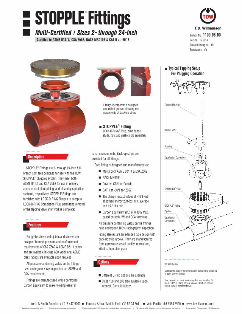
STOPPLE® Fittings are 2- through 24-inch full-branch split tees designed for use with the TDW STOPPLE® plugging system. They meet both ASME B31.3 and CSA Z662 for use in refinery and chemical plant piping, and oil and gas pipeline systems, respectively. STOPPLE Fittings are furnished with LOCK-O-RING Flanges to accept a LOCK-O-RING Completion Plug, permitting removal of the tapping valve after work is completed.
Descriptionharsh environments. Back-up strips are provided for all fittings.
Each fitting is designed and manufactured as:
Meets both ASME B31.3 & CSA Z662
NACE MR0103
Covered CRN for Canada
CAT II at -50°F for Z662
The charpy impact values at -50°F with absorbed energy 20ft-lbs min. average and 15 ft-lbs min.
Carbon Equivalent (CE) of 0.40% Max, based on both IIW and CSA formulas
All pressure containing welds on the fittings have undergone 100% radiography inspection.
Fitting sleeves are an extruded type design with back-up strip groove. They are manufactured from a pressure vessel quality, normalized, killed carbon steel plate.
Flange-to-sleeve weld joints and sleeves are designed to meet pressure and reinforcement requirements of CSA Z662 & ASME B31.3 codes and are available in class 600. Additional ASME class ratings are available upon request.
All pressure-containing welds on the fittings have undergone X-ray inspection per ASME and CSA requirements.
Fittings are manufactured with a controlled Carbon Equivalent to make welding easier in
Features
Different O-ring options are available.
Class 150 and 300 also available upon request. Consult factory.
Options
STOPPLE® FittingLOCK-O-RING® Plug, blind flange, studs, nuts and gasket sold separately
Fittings incorporate a designed and milled groove, allowing the placements of back-up strips
STOPPLE® Fittings
Multi-Certified / Sizes 2- through 24-inch Certified to ASME B31.3, CSA Z662, NACE MR0103 & CAT II at -50° F
North & South America: +1 918 447 5000 Europe / Africa / Middle East: +32 67 28 3611 Asia Pacific: +65 6364 8520 www.tdwilliamson.comData subject to change without notice. / Dimensions not for construction unless certified. / ® Registered trademark of T.D. Williamson, Inc. in the United States and other countries. / TM Trademark of T.D. Williamson, Inc. in the United States and other countries. / © Copyright 2014 All rights reserved. T.D. Williamson, Inc.

T C - 0 1 3 6 - X X 6 0 - X 0
Example: TC-0136-1260-10 is a STOPPLE® Fitting with 12" (run) x 12" (branch), with a RF standard weight flange, dual certified to A350 LF2 CL1 and A105 N flange material, BUNA-N O-rings, class 600, and A 537 CL 1 TDW Std. sleeve material with back-up strips.
1100.008.00 Pg. 2
North & South America: +1 918 447 5000 Europe / Africa / Middle East: +32 67 28 3611 Asia Pacific: +65 6364 8520 www.tdwilliamson.comData subject to change without notice. / Dimensions not for construction unless certified. / ® Registered trademark of T.D. Williamson, Inc. in the United States and other countries. / TM Trademark of T.D. Williamson, Inc. in the United States and other countries. / © Copyright 2014 All rights reserved. T.D. Williamson, Inc.
O-Ring Material
Option O-Ring Material Temperature Ratings 00 BUNA-N, Low Temperature -65°F to 250°F Max 10 BUNA-N, Regular -20°F to 212°F Max 20 Viton, Regular -15°F to 400°F Max 30 Viton, Low Temperature -55°F to 400°F Max 40 EPDM - 20°F to 250°F Max (500°F Max for steam)
STOPPLE® Fitting Size
Size (Nom.) Dim. H Dim. L Dim D Inches Inches Inches Inches 02 8.368 5.750 2.469 03 8.718 7.625 3.625 04 7.281 10.750 4.656 06 9.109 14.000 6.781 08 10.813 16.500 8.813 10 12.797 20.000 10.844 12 13.953 22.000 12.968 14 14.938 26.000 14.220 16 16.563 30.000 16.220 20 20.204 36.000 20.220 24 22.375 43.000 24.220
Material Size Sleeve Material Flange Material 2-3 Dual certified to A 234 WPB & A 420 WPL6 Dual certified to A 350 LF2 CL1 & A 105 N 4-24 A 537 CL1 Dual certified to A 350 LF2 CL1 & A 105 N
Dimensions and Part Numbers
STOPPLE ® Fittings Multi-Certified to ASME B31.3, CSA Z662, NACE MR0103 & CAT II at -50°F – Sizes 2- through 24-inch
L
H H
D
* NOTE: For 2-inch STOPPLE® Fitting, the corrosion allowance is .034 inches.
STOPPLE® Fitting Design Class
Part Number Option 60 600 LB
Maximum Allowable Operating Pressure (in psi) @ -50 to 100°F Size (Nom.) Weight CSA Z662 f/CAT II ASME B31.3 Class Inches (Lbs.) MAOP (in psi) with .72 DF MAOP (in psi) with .062" Corrosion Allowance 600 LB 02 60 1480 1195 * 03 65 1480 825
04 65 1480 1315 06 120 1480 945 08 160 1480 750 10 300 1480 825 12 400 1480 820 14 540 1480 815 16 1000 1480 875 20 1230 1480 905 24 1900 1480 935

Toll Free
1-888-TDWmSon (839-6766)
LOCK-O-RING® Flanges and Plugs are used as a means of recovering tapping valves after a STOPPLE® Plugging Machine operation. They are used in new construction to permit future expansion of a pipeline or a piping system.
Providing a pressure-tight seal over the tapped holes, LOCK-O-RING Flanges eliminate the need for valves until such time as valves may be necessary. For example, fittings with LOCK-O-RING Flanges and Plugs are installed on the line during construction. Later, when branch connections are needed, valves can be installed on the fittings and the LOCK-O-RING Plugs removed with a tapping machine. In some applications, LOCK-O-RING Flanges entirely eliminate the need for permanent valves.
LOCK-O-RING Flanges are drilled and faced to match ASME Class 150, 300 or 600 flanges.
LOCK-O-RING Flanges are mounted on STOPPLE® Fittings. They are also used on reduced branch fittings and plain nipples (See Bulletin 1100.001.00).
For pig guides in side openings, a special flow-through LOCK-O-RING® assembly with guide bars will allow full flow into a branch line and will permit pigs to traverse the opening.
Description Features
LOCK-O-RING® Plug with Scarfed Nipple
LOCK-O-RING® Flange
Patented in the United States and in foreign countries.ISO 9001 Certified
LOCK-O-RING® Plugs can be welded to scarfed pipe spacers to install original coupons inside tapped holes to eliminate pigging hazards.
STOPPLE® Fitting
PipelineCoupon (rotated for clarity)
LOCK-O-RING® Plug With Scarfed Nipple For Coupon
Flow-Through LOCK-O-RING® With Pig Guide Bars
Bulletin No: 1120.001.02Date: April 2009Cross Indexing No: n/aSupersedes: October 2002
LOCK-O-RING® Flanges & PlugsSizes: 4- Through 36-inch
T.D. Williamson, Inc. P.O. Box 3409 Tulsa, Oklahoma 74101-3409 918-447-5100 Fax: 918-446-6327 www.tdwilliamson.comData subject to change without notice. / Dimensions not for construction unless certified. / ® Registered trademark of T.D. Williamson, Inc. in the United States and foreign countries / TM Trademark of T.D. Williamson, Inc. in the United States and foreign countries / © Copyright 2009. All rights reserved T.D. Williamson, Inc. / Printed in USA
Dimensions and Part Numbers
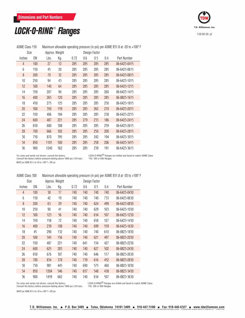
ASME Class 150 Maximum allowable operating pressure (in psi) per ASME B31.8 at -20 to +100º F Size Approx. Weight Design Factor Inches DN Lbs. Kg. 0.72 0.6 0.5 0.4 Part Number 4 100 27 12 285 285 285 285 06-6423-0415 6 150 45 20 285 285 285 285 06-6423-0615 8 200 70 32 285 285 285 285 06-6423-0815 10 250 94 43 285 285 285 285 06-6423-1015 12 300 140 64 285 285 285 285 06-6423-1215 14 350 207 94 285 285 285 260 06-6423-1415 16 400 265 120 285 285 285 285 06-8823-1615 18 450 275 125 285 285 285 250 06-6423-1815 20 500 350 159 285 285 262 210 06-6423-2015 22 550 406 184 285 285 285 238 06-6423-2215 24 600 487 221 285 279 233 186 06-6423-2415 26 650 680 308 285 285 285 259 06-6423-2615 28 700 666 302 285 285 250 200 06-6423-2815 30 750 870 395 285 285 242 194 06-6423-3015 34 850 1101 500 285 285 258 206 06-6423-3415 36 900 1240 562 285 285 239 191 06-6423-3615
For sizes and series not shown, consult the factory. Consult the factory before pressure-testing above 1800 psi (124 bar).
LOCK-O-RING® Flanges are drilled and faced to match ASME Class 150, 300 or 600 flanges.
ASME Class 300 Maximum allowable operating pressure (in psi) per ASME B31.8 at -20 to +100º F Size Approx. Weight Design Factor Inches DN Lbs. Kg. 0.72 0.6 0.5 0.4 Part Number 4 100 38 17 740 740 740 740 06-6423-0430 6 150 42 19 740 740 740 733 06-6423-0630 8 200 63 29 740 740 624 499 06-6423-0830 10 250 90 41 740 740 629 503 06-6423-1030 12 300 123 56 740 740 634 507 06-6423-1230 14 350 158 72 740 740 658 527 06-6423-1430 16 400 239 108 740 740 699 559 06-6423-1630 18 45 290 132 740 740 740 610 06-8823-1830 20 500 345 156 740 740 621 497 06-8823-2030 22 550 487 221 740 641 534 427 06-8823-2230 24 600 625 283 740 740 627 502 06-8823-2430 26 650 676 307 740 740 646 517 06-8823-2630 28 700 834 378 740 739 616 452 06-8823-2830 30 750 981 445 740 690 575 460 06-8823-3030 34 850 1204 546 740 657 548 438 06-8823-3430 36 900 1459 662 740 740 634 507 06-8823-3630
For sizes and series not shown, consult the factory. Consult the factory before pressure-testing above 1800 psi (124 bar).
LOCK-O-RING® Flanges are drilled and faced to match ASME Class 150, 300 or 600 flanges.
MAOP per ASME B31.4 at -20 to +180º F = 285 psi
MAOP per ASME B31.4 at -20 to +180º F = 285 psi
LOCK-O-RING ® Flanges 1120.001.02- p2
T.D. Williamson, Inc. P.O. Box 3409 Tulsa, Oklahoma 74101-3409 918-447-5100 Fax: 918-446-6327 www.tdwilliamson.comData subject to change without notice. / Dimensions not for construction unless certified. / ® Registered trademark of T.D. Williamson, Inc. in the United States and foreign countries / TM Trademark of T.D. Williamson, Inc. in the United States and foreign countries / © Copyright 2009. All rights reserved T.D. Williamson, Inc. / Printed in USA

Dimensions and Part Numbers
LOCK-O-RING® Flanges ASME Class 600
Maximum allowable operating pressure (in psi) per ASME B31.8 at -20 to +100º F Size Approx. Weight Design Factor Inches DN Lbs. Kg. 0.72 0.6 0.5 0.4 Part Number 4 100 46 21 1480 1480 1480 1411 06-6423-0460 6 150 66 30 1480 1372 1140 915 06-6423-0660 8 200 111 50 1480 1480 1304 1020 06-6423-0860 10 250 180 82 1480 1480 1255 1004 06-6423-1060 12 300 225 102 1480 1270 1058 847 06-6423-1260 14 350 334 151 1480 1350 1125 900 06-6423-1460 16 400 481 218 1480 1293 1078 862 06-8823-1660 18 450 531 241 1480 1313 1094` 875 06-8823-1860 20 500 590 268 1480 1313 1094 875 06-8823-2060 22 550 730 331 1480 1313 1094 875 06-8823-2260 24 600 923 419 1480 1313 1094 875 06-8823-2460 26 650 1060 481 1480 1199 999 799 06-8823-2660 28 700 1137 516 1480 1239 1032 826 06-8823-2860 30 750 1227 556 1480 1239 1032 826 06-8823-3060 34 850 1472 668 1480 1238 1032 825 06-8823-3460 36 900 1741 790 1480 1238 1032 825 06-8823-3660
For sizes and series not shown, consult the factory. Consult the factory before pressure-testing above 1800 psi (124 bar).
LOCK-O-RING® Flanges are drilled and faced to match ASME Class 150, 300 or 600 flanges.
LOCK-O-RING® Plugs ASME Class 150, 300, 600
LOCK-O-RING® Plug Spare O-Rings*
ASME Class 150, 300, 600 Part Number
00-1250-000100-1250-000200-1250-000300-1250-000400-1250-000500-1250-000600-7877-000100-7877-000200-7877-000300-7877-000400-7877-000500-7877-000600-7877-000700-7877-000800-7877-001000-7877-0011
*Standard O-Rings are Buna-N
LOCK-O-RING® Flange
LOCK-O-RING® Plug
Maximum allowable operating pressure (in psi) per ASME B31.8 at -20 to +100º F Size Approx. Weight Design Factor Inches DN Lbs. Kg. 0.72 0.60 0.50 0.40 Part Number 4 100 9 4 1480 1480 1480 1480 07-0312-0000 6 150 19 9 1480 1480 1480 1480 07-1265-0000 8 200 35 16 1480 1480 1480 1480 07-1266-0000 10 250 56 25 1480 1480 1480 1480 07-0286-0000 12 300 76 34 1480 1480 1480 1480 07-0287-0000 14 350 95 43 1480 1480 1480 1480 07-0288-0000 16 400 140 63 1480 1480 1480 1480 07-0289-0000 18 450 200 91 1480 1480 1480 1480 07-0290-0000 20 500 260 118 1480 1480 1480 1350 07-0291-0000 22 550 320 145 1480 1480 1480 1480 07-0292-0000 24 600 383 174 1480 1480 1480 1480 07-0293-0000 26 650 370 168 1480 1480 1480 1345 07-0294-0000 28 700 273 124 1480 1480 1480 1235 07-0295-0000 30 750 520 236 1480 1480 1480 1360 07-0296-0000 34 850 715 324 1480 1480 1480 1365 07-0298-0000 36 900 850 386 1480 1480 1480 1350 07-0299-0000Consult the factory for larger sizes.
LOCK-O-RING ® Flanges & Plugs 1120.001.02- p3
T.D. Williamson, Inc. P.O. Box 3409 Tulsa, Oklahoma 74101-3409 918-447-5100 Fax: 918-446-6327 www.tdwilliamson.comData subject to change without notice. / Dimensions not for construction unless certified. / ® Registered trademark of T.D. Williamson, Inc. in the United States and foreign countries / TM Trademark of T.D. Williamson, Inc. in the United States and foreign countries / © Copyright 2009. All rights reserved T.D. Williamson, Inc. / Printed in USA

Removable Plug Holder
Boring bar of tapping machine is retracted after releasing plug holder.
Valve
Once the plug is lowered into the LOCK-O-RING® Flange, the ring segments are advanced into the groove of the plug.
LOCK-O-RING® Plugs with Scarfed Nipple for Use with TDW STOPPLE® Fittings
Size ASME Class 150 ASME Class 300 ASME Class 600 Inches DN Part Number Part Number Part Number 4 100 07-1267-0004 07-1268-0004 07-1270-0004 6 150 07-1267-0006 07-1268-0006 07-1270-0006 8 200 07-1267-0008 07-1268-0008 07-1270-0008 10 250 07-1267-0010 07-1268-0010 07-1270-0010 12 300 07-1267-0012 07-1268-0012 07-1270-0012 14 350 07-1267-0014 07-1268-0014 07-1270-0014 16 400 07-1267-0016 07-1268-0016 07-1270-0016 18 450 07-1267-0018 07-1268-0018 07-1270-0018 20 500 07-1267-0020 07-1268-0020 07-1270-0020 22 550 07-1267-0022 07-1268-0022 07-1270-0022 24 600 07-1267-0024 07-1268-0024 07-1270-0024 26 650 07-1267-0026 07-1268-0026 07-1270-0026 28 700 07-1267-0028 07-1268-0028 07-1270-0028 30 750 07-1267-0030 07-1268-0030 07-1270-0030 34 850 07-1267-0034 07-1268-0034 07-1270-0034 36 900 07-1267-0036 07-1268-0036 07-1270-0036
LOCK-O-RING® Plug with Scarfed Nipple
Plug Holder
LOCK-O-RING® Plug (typical 16” 400 mm, and larger)
LOCK-O-RING® Plug (typical 14”, 350 mm, and smaller)
Ring Segment Groove
Buna N O-Ring
Ball Check Valve
LOCK-O-RING® Flange
Allen Wrench
Pipe Plug
Retainer Rod
Plug Holder
Boring Bar of Tapping Machine
Pressure Relief
Ball Seat
Ball Check Valve
Spring Compressed
LOCK-O-RING® Flange
LOCK-O-RING® Plug
Buna N O-Ring
Retainer Ring Segment
Retainer Ring Screw
LOCK-O-RING® Flange
O-Ring
Allen Wrench
Pipe Plug
This drawing shows how the ball check valve, when depressed by the retainer rod of the tapping machine, equalizes pressure during installation of the LOCK-O-RING® Plug.
Ring segment extended position (cannot go farther)
Dimensions and Part Numbers
LOCK-O-RING® Plugs 1120.001.02- p4
T.D. Williamson, Inc. P.O. Box 3409 Tulsa, Oklahoma 74101-3409 918-447-5100 Fax: 918-446-6327 www.tdwilliamson.comData subject to change without notice. / Dimensions not for construction unless certified. / ® Registered trademark of T.D. Williamson, Inc. in the United States and foreign countries / TM Trademark of T.D. Williamson, Inc. in the United States and foreign countries / © Copyright 2009. All rights reserved T.D. Williamson, Inc. / Printed in USA
Typical Application
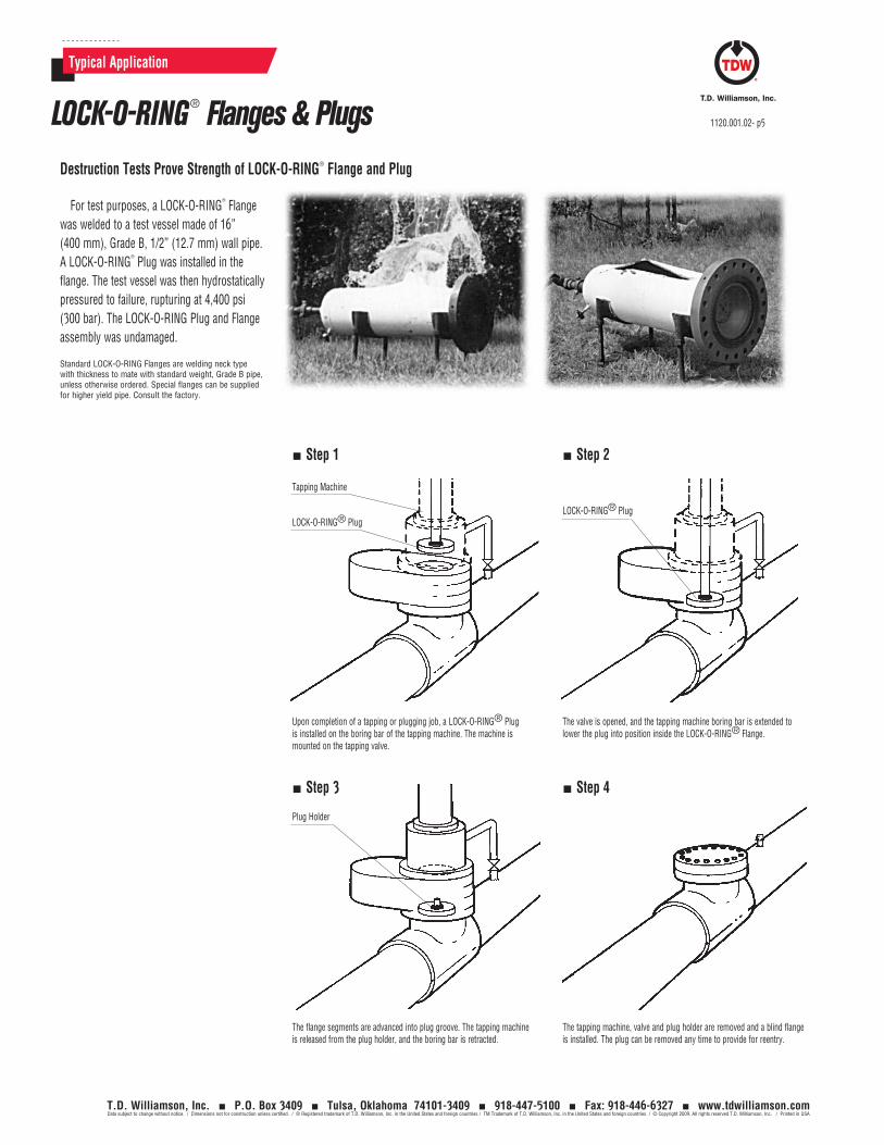
Destruction Tests Prove Strength of LOCK-O-RING® Flange and Plug
For test purposes, a LOCK-O-RING®
Flange was welded to a test vessel made of 16” (400 mm), Grade B, 1/2” (12.7 mm) wall pipe. A LOCK-O-RING
®
Plug was installed in the flange. The test vessel was then hydrostatically pressured to failure, rupturing at 4,400 psi (300 bar). The LOCK-O-RING Plug and Flange assembly was undamaged.
Standard LOCK-O-RING Flanges are welding neck type with thickness to mate with standard weight, Grade B pipe, unless otherwise ordered. Special flanges can be supplied for higher yield pipe. Consult the factory.
Upon completion of a tapping or plugging job, a LOCK-O-RING® Plug is installed on the boring bar of the tapping machine. The machine is mounted on the tapping valve.
The flange segments are advanced into plug groove. The tapping machine is released from the plug holder, and the boring bar is retracted.
The valve is opened, and the tapping machine boring bar is extended to lower the plug into position inside the LOCK-O-RING® Flange.
The tapping machine, valve and plug holder are removed and a blind flange is installed. The plug can be removed any time to provide for reentry.
Tapping Machine
LOCK-O-RING® PlugLOCK-O-RING® Plug
Plug Holder
Step 1 Step 2
Step 3 Step 4
LOCK-O-RING® Flanges & Plugs 1120.001.02- p5
T.D. Williamson, Inc. P.O. Box 3409 Tulsa, Oklahoma 74101-3409 918-447-5100 Fax: 918-446-6327 www.tdwilliamson.comData subject to change without notice. / Dimensions not for construction unless certified. / ® Registered trademark of T.D. Williamson, Inc. in the United States and foreign countries / TM Trademark of T.D. Williamson, Inc. in the United States and foreign countries / © Copyright 2009. All rights reserved T.D. Williamson, Inc. / Printed in USA
Related Documents